JP2015102152A - Clip, and pillar garnish attachment structure - Google Patents
Clip, and pillar garnish attachment structure Download PDFInfo
- Publication number
- JP2015102152A JP2015102152A JP2013242774A JP2013242774A JP2015102152A JP 2015102152 A JP2015102152 A JP 2015102152A JP 2013242774 A JP2013242774 A JP 2013242774A JP 2013242774 A JP2013242774 A JP 2013242774A JP 2015102152 A JP2015102152 A JP 2015102152A
- Authority
- JP
- Japan
- Prior art keywords
- clip
- seat
- pillar garnish
- tether
- mounting hole
- Prior art date
- Legal status (The legal status is an assumption and is not a legal conclusion. Google has not performed a legal analysis and makes no representation as to the accuracy of the status listed.)
- Pending
Links
Images


Abstract
Description
本発明は、クリップをボデーに取り付ける際にクリップの不完全嵌合(以下、「半嵌合」とも云う)の危険性を防止できるクリップ、および該クリップを用いたピラーガーニッシュ取付構造に関する。 The present invention relates to a clip that can prevent a risk of incomplete fitting of a clip (hereinafter also referred to as “half-fitting”) when the clip is attached to a body, and a pillar garnish attachment structure using the clip.
特許文献1は、カーテンエアバッグ(以下、CSAともいう。CSAはCurtain Shield Airbag の略である)を収納したピラーガーニッシュをAピラーに取り付けるとともに、CSA展開時にピラーガーニッシュの飛散を防止したテザークリップを開示している。
図11は、本発明の開発途中で検討された比較例のクリップ(以下、比較クリップともいう)111を示す。図11に示すように、特許文献1の従来クリップを含み比較クリップ111は、互いに対向する一対の係止爪131を有する。一対の係止爪131の外側面は、クリップ111がボデーのクリップ取付孔を挿通する時にクリップ取付孔内面に摺動する摺動面149となっている。摺動面149は、クリップ軸方向に滑らかである。
FIG. 11 shows a
図10において、点線は比較クリップのクリップ取付孔への挿入荷重対ストローク特性を示す。この特性からわかるように、係止爪111がクリップ取付孔縁部に完全に掛かる正規位置Aから少し手前では、クリップ挿入荷重が低く、またはマイナスになり、正規位置A付近でクリップ挿入荷重が急激に高くなる。
In FIG. 10, a dotted line shows the insertion load to the clip mounting hole of the comparative clip versus the stroke characteristic. As can be seen from this characteristic, the clip insertion load is low or minus slightly before the normal position A where the
しかし、比較クリップには、つぎの課題がある。
クリップを強く押さないと係止爪がクリップ取付孔縁部に完全には掛からない。係止爪が正規位置まで来ていないにもかかわらず、正規位置A付近でクリップ挿入荷重が高くなっているため、係止爪が正規位置に来たと誤判断してAピラーガーニッシュの押し込みを止めると、クリップがボデーに対して半嵌合となる。クリップがボデーに対し半嵌合にある時、Aピラーガーニッシュは正規組み付け位置に近いため、Aピラーガーニッシュの表面外観からはクリップの半嵌合を視認することは困難である。
However, the comparison clip has the following problems.
If the clip is not pushed firmly, the latching claw will not completely hook onto the edge of the clip mounting hole. Even though the locking claw has not reached the normal position, the clip insertion load is high in the vicinity of the normal position A. Therefore, it is erroneously determined that the locking claw has reached the normal position, and the push-in of the A pillar garnish is stopped. Then, the clip is half-fitted to the body. When the clip is half-fitted to the body, the A-pillar garnish is close to the normal assembly position, so it is difficult to see the half-fitting of the clip from the surface appearance of the A-pillar garnish.
本発明の目的は、クリップをボデーに取り付ける際に、クリップの半嵌合の危険性を防止または軽減できるクリップを提供することである。 An object of the present invention is to provide a clip that can prevent or reduce the risk of half-fitting of the clip when the clip is attached to the body.
上記目的を達成する本発明のクリップおよびピラーガーニッシュ取付構造は、つぎの態様をとることができる。なお、括弧付きの符号は図面に現れる部材番号に対応する。 The clip and pillar garnish mounting structure of the present invention that achieves the above object can take the following modes. In addition, the code | symbol with a parenthesis respond | corresponds to the member number which appears in drawing.
本発明の第1の態様では、クリップ(11)は、座部(25)と、座部(25)から離れる方向に延びる軸部(21)と、軸部(21)との結合部(41)から座部(25)側に延びて自由端で終わる係止爪(31)と、を備える。
係止爪(31)は、軸部(21)の外面(29)よりもクリップ中心軸線(11a)から離れる方向に突出する突出部(45)を有する。
突出部(45)は、クリップ軸方向に結合部(41)から座部(25)側に延びクリップ取付孔(93)内面に摺動する摺動面(49)と、摺動面(49)の座部(25)側端からクリップ中心軸線(11a)側に延び座部(25)に対向する座部対向面(51)と、を有している。
突出部(45)の摺動面(49)には、座部対向面(51)から結合部(41)側に隔たった位置に、結合部(41)から座部(25)側に向かって見た時にクリップ中心軸線(11a)から離れる側に変位しクリップ取付孔(93)へのクリップ挿入荷重を高める段差(55)が設けられている。
In the first aspect of the present invention, the clip (11) includes a seat portion (25), a shaft portion (21) extending in a direction away from the seat portion (25), and a joint portion (41) between the shaft portion (21). ) To the seat (25) side and ends with a free end.
The locking claw (31) has a protrusion (45) that protrudes in a direction away from the clip center axis (11a) rather than the outer surface (29) of the shaft (21).
The protrusion (45) includes a sliding surface (49) extending in the clip axial direction from the coupling portion (41) toward the seat (25) and sliding on the inner surface of the clip mounting hole (93), and a sliding surface (49). A seat-facing surface (51) extending from the side end of the seat (25) toward the clip center axis (11a) and facing the seat (25).
The sliding surface (49) of the projecting portion (45) is located at a position spaced from the seat facing surface (51) to the coupling portion (41) side and from the coupling portion (41) to the seat portion (25) side. When viewed, a step (55) is provided that is displaced away from the clip center axis (11a) and increases the clip insertion load into the clip mounting hole (93).
本発明の第2の態様では、上記第1の態様において、段差(55)の座部対向面(51)からのクリップ軸方向隔たり量が、クリップ(11)のクリップ取付孔(93)への挿入不足があった場合に生じる、クリップ(11)により取り付けられる部品の正規位置からのずれを外観から目視で判断できる量以上とされている。 In the second aspect of the present invention, in the first aspect, the distance in the axial direction of the clip from the seat-facing surface (51) of the step (55) is the distance from the clip mounting hole (93) of the clip (11). The deviation from the normal position of the component attached by the clip (11), which occurs when there is insufficient insertion, is set to an amount that can be visually determined from the appearance.
本発明の第3の態様では、上記第1の態様または第2の態様において、クリップ(11)がテザークリップである。 According to a third aspect of the present invention, in the first aspect or the second aspect, the clip (11) is a tether clip.
本発明の第4の態様では、ピラーガーニッシュ取付構造(1)が、上記第3の態様のクリップ(11)を用いてピラーガーニッシュ(81)をボデー(91)に取り付けた構成からなる。 In the fourth aspect of the present invention, the pillar garnish attachment structure (1) has a structure in which the pillar garnish (81) is attached to the body (91) using the clip (11) of the third aspect.
第1の態様に係るクリップによれば、つぎの効果が得られる。
クリップの摺動面に、座部対向面から結合部側に隔たった位置に段差を設けたので、クリップをボデーのクリップ取付孔に挿入していく時、ボデーのクリップ取付孔部位が段差を乗り越える付近において、クリップ挿入荷重が意図的に高くなる。
この結果、クリップのボデーのクリップ取付孔への押し込み力が不十分な場合は、段差でクリップの挿入が止められる。その場合は、クリップを用いてボデーに取り付けられる部品(たとえば、Aピラーガーニッシュ)がその周囲のボデー部品から浮き上がっているので、外観から目視で、クリップのクリップ取付孔への嵌合が半嵌合であることがわかる。半嵌合の場合は、さらに強く押せばよい。
クリップのボデーのクリップ取付孔への押し込み力が十分な場合は、段差がボデーのクリップ取付孔周縁部を乗り越える。その場合、段差がクリップ取付孔周縁部を乗り越える時の勢いで、係止爪が完全にボデーのクリップ取付孔周縁部にクリップ軸方向に掛かる位置まで一気にクリップを押し込むことができる。そのため、段差から正規位置までの途中のクリップ部位がクリップ取付孔周縁部で止まって半嵌合になるおそれが大幅に軽減される。
また、クリック感(節度感)により作業者も正規嵌合を感じとることができる。
According to the clip concerning the 1st mode, the following effect is acquired.
Since the step is provided on the sliding surface of the clip at a position separated from the seat facing surface to the coupling portion side, when the clip is inserted into the clip attachment hole of the body, the clip attachment hole part of the body gets over the step. In the vicinity, the clip insertion load is intentionally high.
As a result, when the pushing force of the clip body into the clip mounting hole is insufficient, the insertion of the clip is stopped at the step. In that case, the parts (for example, A-pillar garnish) that can be attached to the body using the clip are lifted from the surrounding body parts. It can be seen that it is. In the case of half-fitting, it may be pushed more strongly.
When the pushing force of the clip body into the clip mounting hole is sufficient, the step gets over the peripheral edge of the clip mounting hole of the body. In that case, it is possible to push the clip at a stroke to the position where the locking claw is completely engaged with the peripheral edge of the clip mounting hole of the body in the clip axial direction with the momentum when the step gets over the peripheral edge of the clip mounting hole. Therefore, the possibility that the clip part on the way from the step to the normal position stops at the peripheral part of the clip mounting hole and is half-fitted is greatly reduced.
In addition, the operator can feel a normal fit due to a click feeling (moderation feeling).
第2の態様に係るクリップによれば、つぎの効果が得られる。
段差の座部対向面からの隔たり量が、クリップのクリップ取付孔への挿入不足があった場合に生じる、クリップ11により取り付けられる部品の正規位置からの浮き上がりを外観から目視で判断できる量以上とされているため、半嵌合の場合は、外観から容易に半嵌合になっていることを視認できる。
According to the clip concerning the 2nd mode, the following effect is acquired.
The amount of separation from the seat-facing surface of the step is greater than the amount by which the lifting from the normal position of the component attached by the
第3の態様に係るクリップによれば、テザークリップにおいても、第1の態様または第2の態様によるクリップの効果と同じかまたはそれに準じる効果が得られる。すなわち、テザークリップをボデーに完全嵌合にて取り付けることができ、テザークリップを用いてピラーガーニッシュを確実に組み付けることができる。その結果、CSA展開時に、テザークリップに軸方向荷重がかかった時のテザークリップの耐抜去性とそれによるピラーガーニッシュの飛散防止性が、それぞれ、向上する。 According to the clip according to the third aspect, even in the tether clip, the same effect as or equivalent to the effect of the clip according to the first aspect or the second aspect is obtained. That is, the tether clip can be attached to the body by complete fitting, and the pillar garnish can be reliably assembled using the tether clip. As a result, when the CSA is deployed, the removal resistance of the tether clip when the axial load is applied to the tether clip and the prevention of scattering of the pillar garnish are improved.
第4の態様に係るピラーガーニッシュ取付構造によれば、第3の態様のクリップによる効果と同じかそれに準じる効果が得られる。その結果、テザークリップの組付性が確実なことによりピラーガーニッシュの組付も確実になること、およびCSA展開時におけるテザークリップの耐抜去性が向上することによりピラーガーニッシュの飛散防止性も向上するなどの効果が得られる。 According to the pillar garnish attachment structure according to the fourth aspect, the same effect as that obtained by the clip according to the third aspect or an effect equivalent thereto can be obtained. As a result, the assembly of the pillar garnish is ensured by ensuring the assembling property of the tether clip, and the prevention of the scattering of the pillar garnish is also improved by improving the removal resistance of the tether clip at the time of CSA deployment. Effects such as can be obtained.
本発明の一実施例に係るクリップ11、およびクリップ11がテザークリップである場合におけるテザークリップと、そのテザークリップを用いてピラーガーニッシュをボデーに取り付けたピラーガーニッシュ取付構造(ピラーガーニッシュ取付装置と云ってもよい)1を、図1−図10を参照して説明する。ピラーガーニッシュ取付構造1の主要部はクリップ11であるため、クリップ11とピラーガーニッシュ取付構造1とは主要部が同じである。
図1−図7はクリップ11と、クリップ11がテザークリップである場合におけるテザークリップを示し、図8および図9はピラーガーニッシュ取付構造1を示す。図8、図9において、FRは車両前方を示し、INは車両左右方向の内側方向を示す。
The
1 to 7 show a
<<構成>>
〔クリップの構成〕
まず、クリップ11の構成を、作用と共に、説明する。図1−図7は、クリップ11がテザークリップ(クリップと同じであるからクリップと同じ符号を付す)11からなる場合を示しているが、クリップ11はテザークリップ11以外のクリップであってもよく、たとえば、CSAをボデーに固定する通常の固定クリップであってもよい。
<< Configuration >>
[Clip configuration]
First, the configuration of the
クリップ11は可撓性を有する樹脂材からなる。樹脂材は、たとえばポリヘキサメチレンアジポアミドである。ただし、可撓性を有し必要な強度をもつ樹脂材であれば、それ以外の樹脂材であってもよい。
The
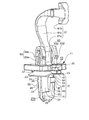
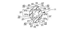
クリップ11はクリップ中心軸線11aを有する。クリップ11は、単一の座部25と、座部25から離れる方向に延びる単一の軸部(ボデー取付部、または、脚部とも云う)21と、クリップ軸方向に座部25から離れた位置にある軸部21との結合部41から座部25側に延びて自由端で終わる少なくとも一対の係止爪31と、を備えている。係止爪31は複数対あってもよい。
The
軸部21は、座部25と直交する。軸部21の中心軸線はクリップ11の中心軸線11aと一致する。軸部21は、中空である。クリップ中心軸線11aと直交する方向における軸部21の断面の外形は、ほぼ円形、またはほぼ長方形である。長方形は正方形である場合を含む。
The
中空軸部21の互いに対向する部位に一対の開口部が設けられ、そこに一対の係止爪31が設けられる。一対の係止爪31は、クリップ軸方向と直交する方向に、互いに対向している。
A pair of openings are provided in the mutually opposing portions of the
各係止爪31は、結合部41で軸部21の壁に結合している。各係止爪31は、軸部21との結合部41を除いて軸部21および座部25から切り離されている。すなわち、軸部21との結合部41を除いて、軸部21および座部25と、係止爪31との間には、スリット43が存在する。係止爪31は、結合部41から座部25側に向かって延びる。クリップ11が可撓性を有する樹脂材からなるため、係止爪31は、クリップ中心軸線11aに接近、離反する方向に、すなわち、結合部41まわりに倒れ、起立する方向に、弾性変形可能である。
Each locking
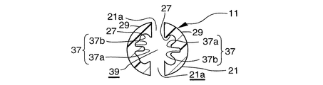
一対の係止爪31は、互いに対向する内側面35と、内側面35と反対側にある外側面33と、を有する。内側面35は、クリップ中心軸線11aに対向する。一対の係止爪31の内側面35の間は空間部39となっている。空間部39は中空軸部21内の空間部でもある。空間部39は、クリップ軸方向に座部24から離れる方向に延び、軸部21の座部24から遠い側の端部で軸部外部に開放している。
The pair of locking
一対の係止爪31の互いに対向する内側面35には、一対の係止爪31の対向方向に凹凸する凹凸37が形成されている。凹凸37は凸部37aと凹部37bを有する。対向する一対の係止爪31のうち一方の係止爪31の凸部37aと他方の係止爪31の凹部37bとは、一対の係止爪31の対向方向に互いに対向するように形成されている。一対の係止爪31が互いに近づく方向に結合部41まわりに倒れ変形した時に、一対の係止爪31のうち一方の係止爪31の凸部37aが他方の係止爪31の凹部37bに突入するので、凹凸37が設けられない場合に比べて、一対の係止爪31が互いに近づく方向における各係止爪31の倒れ可能変形量が増大し、かつ、各係止爪31の撓み方向(倒れ方向)の曲げ剛性が増大する。
Concavities and
凹凸37は、座部25に近い側の係止爪先端部から、座部25から遠い側の軸部21先端部まで、係止爪31の内側面35と軸部21の内面27の両方にわたって形成されている。凹凸37は、クリップ軸方向における、係止爪31の全長にわたる部分と、係止爪31の結合部41から座部25から遠い側の軸部21先端部までの部分との両方にわたって形成されている。凹凸37の凸部37a、凹部37bは、それぞれ、クリップ軸方向に直線状に延び、クリップ11と同じ成形加工にて形成される。
The
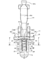
一対の係止爪31の各係止爪31は、突出部45と係止解除部47を有している。突出部45と係止解除部47とは、クリップ軸方向に、互いに離れている。
係止爪31の自由状態(係止爪31に荷重がかかっていない状態)において、突出部45は、軸部21の外面よりも、クリップ中心軸線11aから離れる方向に突出する。すなわち、係止爪31のうち、軸部21の外面よりもクリップ中心軸線11aから離れる方向に突出した部分が、突出部45である。
Each locking
In a free state of the locking claw 31 (a state where no load is applied to the locking claw 31), the protruding
突出部45は、クリップ中心軸線11aに沿う方向における突出部45の少なくとも一部の外面に、クリップ11をクリップ取付孔93に挿入する時に、クリップ取付孔93内周面に摺動する摺動面49と、摺動面49の座部25側端からクリップ中心軸線11a側に延びクリップ軸方向に座部25に対向する座部対向面51を有する。
The
突出部45の摺動面49は、座部対向面51から結合部41側に隔たった位置に、結合部41から座部25側に向かって見た時にクリップ中心軸線11aから離れる側に変位しクリップ取付孔93へのクリップ挿入荷重を高める段差55が設けられている。
The sliding
突出部45の摺動面49は、結合部41から係止爪31の座部25側先端部に向かってクリップ中心軸線11aから離れる方向に延びる傾斜面53と、傾斜面53の座部25側先端からクリップ中心軸線11aから離れる側に変位する段差55と、段差55のクリップ中心軸線11aから遠い側の端部と座部対向面51のクリップ中心軸線11aから遠い側の端部との間にわたってクリップ中心軸線11aに平行かまたはほぼ平行にクリップ軸方向に延びる最大突出面57と、を有する。段差55は、傾斜面53の座部25側先端と最大突出面57の座部25から遠い側の端部との間にわたって延びる。段差55は、クリップ中心軸線11aと直交するかまたはほぼ直交する面内にあってもよい。
The sliding
係止爪31のうち、突出部45の座部対向面51と係止解除部47との間は、クリップ中心軸線11aと平行にクリップ軸方向に延びる軸方向面59である。一対の係止爪31の軸方向面59間距離は、クリップ取付孔93の内径以下であり、クリップ11をボデー91に装着した時にはボデー91が突出部45の座部対向面51と係止解除部47との間に嵌まり込む。また、係止爪31は、結合部41側の外面に、突出部45の摺動面49以外に、クリップ中心軸線11aに平行かまたはほぼ平行に延びる平行面を有していてもよい。
Among the latching
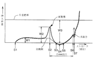
図10は、クリップ11のボデー91への装着時に、クリップ11をボデー91のクリップ取付孔93に挿入する時の挿入荷重対挿入ストローク特性を示している。実線が本発明の段差55を持つクリップ11の場合であり、点線は段差を持たない比較クリップ111の場合である。
FIG. 10 shows insertion load versus insertion stroke characteristics when the
クリップ11をクリップ取付孔93を挿入していく時、ストロークS1で摺動面49の傾斜面53がクリップ取付孔93内面に接触し始める。クリップ11をストロークS1よりさらに挿入していくと、係止爪31がクリップ取付孔93内面で押されて内側に倒れ、その反力で摺動面49の傾斜面53とクリップ取付孔93内面とが摺動接触し、比較的低い挿入荷重W1が生じる。
When the
クリップ11をS1よりもさらに挿入していくと、ストロークS2で段差55がクリップ取付孔93縁部にひっかかり、挿入荷重が急激に増えてW2となる。W2はW1より大きい。ただし、荷重W2は作業を容易にするために所定の作業標準荷重W3以下であることが好ましい。比較クリップ111の場合は段差55に対応する段差が無いので、挿入荷重対ストローク特性に本発明の荷重W2の山に対応する山は現れない。ストロークS3−S5では、最大突出面57がクリップ取付孔93内面に接触する。ストロークS3−S5では、クリップ11はストロークS3−S5の中間にあるストロークS4に向かって引き込まれ、ストロークS4で安定位置をとる。この場合、ストロークS3−S5での挿入荷重はストロークS4位置を最小とするマイナスと考えられる。
When the
ストロークS5以後、急激に挿入荷重が増す。ストロークS5より大きいストロークS6では、最大突出面57の座部25側端がクリップ取付孔93内周面にひっかかっている状態にある。ストロークがS6を少しでも越えると、ボデー91のクリップ取付孔93周縁部がクリップ11の軸方向面59を底面とする溝に嵌まり込む。この時のストロークはS7であり、クリップ11は正規位置Aにある。ストロークS7では、最大突出面57がクリップ取付孔93内周面に接触していないので、クリップ挿入荷重はいったん低下する。この状態では、ボデー91のクリップ取付孔93周縁部が、突出部45の座部対向面51とスペーサ23との間に挟まれて保持されている。クリップ11をストロークS7よりさらに押し込むとスペーサ23の反力が急激に増加し、クリップ挿入荷重は再び急激に増加する。押し込みを止めると、クリップ11はストロークS7の位置に戻る。
After the stroke S5, the insertion load increases rapidly. In the stroke S6 larger than the stroke S5, the end of the
座部対向面51から結合部41側への段差55の隔たり量は、クリップ11のクリップ取付孔93への挿入不足があった場合に生じる、クリップ11により取り付けられる部品の正規位置Aからのずれ(浮き上がり)を外観から目視で判断できる量(たとえば、2mm)以上とされている。
座部対向面51から結合部41側への段差55の隔たり量は、クリップ挿入ストローク基準で(S6−S2)量に対応する。段差55で挿入力にクリック感(節度感)をもたせるためには、段差55を越えた直後に挿入荷重が低いかまたはマイナスのストローク域(S3からS5の領域)が来ることが好ましいので、座部対向面51から結合部41側への段差55の隔たり量(S6−S2)は、クリップ軸方向に、ストローク基準で(S6−S3)量以上離れていることが好ましい。この意味においても、座部対向面51から結合部41側への段差55の隔たり量(S6−S2)は、2mm以上であることが好ましく、さらに好ましくは、2.5mm以上である。ただし、2mm、2.5mmは、軸部21の長さが15mmの場合であり、軸部21の長さが所定の比で増減すると、2mm、2.5mmも同じ比で増減するものとする。
The amount of separation of the
The distance of the
また、段差55の座部対向面51からの隔たり量(S6−S2)が大き過ぎると、荷重W2の山を越えた時にほぼ一定の荷重W1に低下するだけで(W2−W1)量を大きくとれず、クリック感(節度感)を持たせにくくなるため、隔たり量(S6−S2)は4mm以下であることが好ましく、さらに好ましくは、3.5mm以下である。これにより、挿入荷重が荷重W2の山を越えた時にゼロかマイナスの荷重に低下し、段差55の位置で挿入力にクリック感(節度感)をもたせることができる。ただし、4mm、3.5mmは、軸部21の長さが15mmの場合であり、軸部21の長さが所定の比で増減すると、4mm、3.5mmも同じ比で増減するものとする。
Further, if the distance (S6-S2) of the
係止爪31は、クリップ11をクリップ取付孔93に挿入する時に突出部45がクリップ取付孔93の内周面で押されてクリップ中心軸線11aに近づく方向に倒れ変形し、クリップ取付孔93を通り過ぎた時に元の位置(自由状態の位置)に弾性復帰する。元の位置に弾性復帰した後は、突出部45の座部対向面51がボデー91のクリップ取付孔93の周縁部とクリップ軸方向に係合し、クリップ11がクリップ取付孔93から抜けないようになる。
When the
クリップ11をボデー91のクリップ取付孔93へ押し込む時、段差55がクリップ取付孔93周縁部に来ると、段差55がクリップ取付孔93周縁部を乗り越える。その場合、段差55がクリップ取付孔93周縁部を乗り越える時の勢いで、座部対向面51が完全にボデー91のクリップ取付孔93周縁部にクリップ軸方向に掛かる位置まで、すなわちクリップ11がボデー91に完全嵌合する位置まで、一気にクリップ11を押し込むことができる。
When the
係止解除部47は、座部25に近い側の係止爪先端部に設けられ、クリップ中心軸線11aから離れる方向に延びる。係止解除部47のクリップ中心軸線11aから遠い側の外側端は、突出部45の外側端よりもクリップ中心軸線11aから離れた位置にある。係止解除部47のクリップ中心軸線11aから遠い側の外側端は、同じ方向における座部25の外側端よりもクリップ中心軸線11aから離れた位置にある。
The unlocking
サービス時においてクリップ11をクリップ取付孔93から外す時には、一対の突出部45の外側面間距離がクリップ取付孔93の内径かそれ以下となるまで、一対の係止爪31の係止解除部47を互いに近づく方向に押し、ついでクリップ11をクリップ軸方向に引張り、軸部21をクリップ取付孔93から引き抜く。
When the
軸部21には、クリップ軸方向に延び座部25から遠い側の軸部21先端部に開放する割り部21aを有していてもよい。軸部21が割り部21aをもつ場合は、軸部21の座部25から遠い側の先端部は、軸部21の周方向に非連続となる。軸部21が割り部21aを有する場合は、軸部21が半径方向に弾性を有するようになり、クリップ取付孔93に挿入し易くなる一方、クリップ取付孔93の周縁部に引っ掛かり易くなる。
The
クリップ11の軸部21をボデー91のクリップ取付孔93に挿入してボデー91に装着した時、ボデー91は突出部45と係止解除部47との間に位置する。その時、ボデー91は、係止爪31の突出部45の座部対向面51とスペーサ23とによって挟まれる。スペーサ23は、クリップ11と別体のピースであってもよいし、クリップ11と一体に形成されてもよい。図示例は、スペーサ23がクリップ11と一体に形成された一体スペーサからなる場合を示している。スペーサ23はクリップ軸方向の弾性を有し、座部25側からボデー91に接触し、ボデー91とクリップ11間のガタ(隙間)をとる。
以上までの構成は、クリップ11がピラーガーニッシュをボデーに取り付けるテザークリップであろうが、CSAをボデーに取り付けるCSA取付けクリップであろうが、適用可能である。
When the
The above configuration is applicable regardless of whether the
〔テザークリップおよびピラーガーニッシュ取付構造の構成〕
つぎに、クリップ11がテザークリップ(クリップと同じであるため、テザークリップの符号も11とする)である場合のテザークリップ11と、テザークリップ11を用いたピラーガーニッシュ取付構造1の構成を、作用と共に、説明する。
[Configuration of tether clip and pillar garnish mounting structure]
Next, the structure of the
・〔テザークリップとピラーガーニッシュ取付構造との関係〕
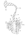
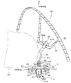
図8、図9に示すように、ピラーガーニッシュ81は、テザークリップ11によってボデー91のピラーのインナーパネル91aに取り付けられる。ピラーガーニッシュ81は、ガーニッシュ本体83と台座部85を有する。台座部85の底壁85aには長方形のテザー部挿通孔87が設けられる。CSA89は、ボデー91であるピラーのインナーパネル91aとガーニッシュ本体83との間の空間に、折り畳まれた状態で収納される。車両衝突時、CSA89が膨張展開される。図9に展開状態にあるCSA89を二点鎖線で示す。
・ [Relationship between tether clip and pillar garnish mounting structure]
As shown in FIGS. 8 and 9, the
・〔テザークリップの構成〕
図1、図2、図6に示すように、テザークリップ11は、テザー部61と係合保持部63を有する。テザー部61と係合保持部63は、図11の比較テザークリップのテザー部と係合保持部と同じ構成であってもよい。
・ [Configuration of tether clip]
As shown in FIGS. 1, 2, and 6, the
テザー部61は、軸部21と反対側に座部25から立ち上がる立ち上がり部61aと、座部25から遠い側の先端に設けられたアンカー部61bと、立ち上がり部61aとアンカー部61bとを連結する連結部61cと、を有する。連結部61cは湾曲していてもよい。連結部61cの湾曲の方向は、ピラーガーニッシュ81の長手方向と直交する方向であってもよいし、またはピラーガーニッシュ81の長手方向であってもよい。
The
アンカー部61bは、ピラーガーニッシュ81の台座部85のテザー部挿通孔87より小さい長方形の外形を有する。テザー部61を台座部85内に挿入する時は、アンカー部61bとテザー部挿通孔87との位相を合わせて、アンカー部61bがテザー部挿通孔87に挿通される。テザー部61が台座部85内に挿入された後、テザークリップ11が中心軸線11aまわりに90度回転されてアンカー部61bが台座部85から抜け外れ不能とされる。テザークリップ11がピラーガーニッシュ81に取り付けられた状態で、ピラーガーニッシュ81がボデー91側に押され、テザークリップ11の軸部21がボデー91のクリップ取付孔93に押し込まれ、テザークリップ11付きピラーガーニッシュ81がボデー91に取り付けられる。図8はテザークリップ11付きピラーガーニッシュ81がボデー91に取り付けられた状態を示す。
The
係合保持部63は、軸部21と反対方向に座部25から立ち上がる。係合保持部63は、テザー部61の立ち上がり部61aの側方に設けられる。係合保持部63は、立ち上がり部61aから離れた位置に設けられる。
The
図4、図8、図9に示すように、係合保持部63は、テザー部挿通孔87が設けられている台座部底壁85aの厚みとほぼ等しい量だけ座部25から立ち上がる立ち上がり部63aと、立ち上がり部63aの先端からさらに座部25から離れる方向に延びるとともに立ち上がり部63aの立ち上がり方向と直交する方向に膨出する膨出部63bを有する。膨出部63bは立ち上がり部63aの立ち上がり方向と直交する方向に弾性をもつように中空形状に形成される。
As shown in FIGS. 4, 8, and 9, the
テザークリップ11をピラーガーニッシュ81に取り付ける時には、係合保持部63を台座部85のテザー部挿通孔87に押し込む。この時、膨出部63bがその膨出量が低減する方向に弾性変形してテザー部挿通孔87を通り抜け、膨出部63bが台座部85内に入る。膨出部63bがテザー部挿通孔87を通り抜けると、膨出部63bが元の位置(自由状態の位置)に弾性復帰し、台座部85を膨出部63bとスペーサ23との間に保持する。この状態を維持したまま、テザークリップ11がボデー91に取り付けられる。
When attaching the
CSA展開時、CSA89によってピラーガーニッシュ81が押されると、テザー部挿通孔87の周縁部が係合保持部63の膨出部63bを座部25から離れる方向に押し、膨出部63bをその膨出量が低減する方向に弾性変形させ、膨出部63bを通り抜ける。これによって、台座部底壁85aが係合保持部63の膨出部63bから外れる。その結果、テザー部61のアンカー部61bが台座部底壁85aのテザー部挿通孔87の周縁部に接触するまで、ピラーガーニッシュ81はボデー91から離れる方向に移動できる。
When the
車両衝突時、CSA89が膨張展開される。CSA89の展開時、膨張するCSA89によってピラーガーニッシュ81が車室側に押されると、アンカー部61bがテザー部挿通孔87の周縁部に接触するまではピラーガーニッシュ81はボデー91から離れる方向に移動でき、インナーパネル91aとの間にCSA89の展開用隙間を作る。図9に示すように、アンカー部61bが台座部底壁85aのテザー部挿通孔87の周縁部に接触すると、ピラーガーニッシュ81はそれ以上移動できなくなり、ピラーガーニッシュ81の車室内方向への飛散が防止される。
When the vehicle collides, the
・〔ピラーガーニッシュ取付構造の構成〕
ピラーガーニッシュ81は、クリップ11と同等かそれよりは硬質のプラスチックからなる。
図9に示すように、CSA89は、車両の衝突時に膨張展開し、インナーパネル91aとガーニッシュ本体83との間に展開用隙間を作り、そこを通して乗員とサイドドアとの間に展開する。この時、テザークリップ11は、ピラーガーニッシュ81が車室内に飛散しないようにピラーガーニッシュ81の所定量以上の移動を拘束する。
・ [Pillar garnish mounting structure configuration]
The
As shown in FIG. 9, the
<<効果>>
つぎに、クリップ11の効果と、クリップ11がテザークリップである場合のテザークリップ11とそれを用いたピラーガーニッシュ取付構造1の効果を説明する。
<< Effect >>
Next, the effect of the
〔クリップの効果〕
クリップ11の摺動面49に、座部対向面51から結合部41側に隔たった位置に段差55を設けたので、クリップ11をボデー91のクリップ取付孔93に挿入していく時、段差55がボデー91のクリップ取付孔93部位を乗り越える付近において、クリップ挿入荷重を意図的に高くすることができる。
[Clip effect]
Since the
この結果、クリップ11のボデー側クリップ取付孔93への押し込み力が不十分な場合は、段差55でクリップ11の挿入が止められる。その場合は、クリップ11を用いてボデー91に取り付けられる部品(たとえば、Aピラーガーニッシュ81)がその周囲のボデー部品から浮き上がっているので、外観から目視で、クリップ11のクリップ取付孔93への嵌合が半嵌合であることがわかる。半嵌合の場合は、さらにAピラーガーニッシュ81を強く押してクリップ11を押し込めば完全嵌合とすることができる。
As a result, when the pushing force of the
クリップ11のボデー側クリップ取付孔93への押し込み力が十分な場合は、段差55がボデー91のクリップ取付孔93周縁部を乗り越える。その場合、段差55がクリップ取付孔93周縁部を乗り越える時の勢いで、係止爪93が完全にボデー91のクリップ取付孔93周縁部にクリップ軸方向に掛かる位置まで一気にクリップ11を押し込むことができる。そのため、クリップ取付孔93周縁部が段差55から正規位置までの途中で止まって半嵌合になるおそれが大幅に軽減される。
また、段差55がクリップ取付孔93周縁部を乗り越える時のクリック感(節度感)により作業者も正規嵌合を感じとることができる。
When the pushing force of the
In addition, the operator can feel a normal fit due to a click feeling (moderation feeling) when the
段差55の座部対向面51からの隔たり量が2mm以上である場合、半嵌合が生じた時には、クリップ11を用いてボデー91に取り付けられる部品(たとえば、Aピラーガーニッシュ81)はまわりのボデー部品と2mm以上の段状を形成するので、外観から容易にクリップ11のボデー91への取り付けが半嵌合になっていることを視認できる。半嵌合を視認した場合は、さらにAピラーガーニッシュ81を強く押してクリップ11を押し込んで完全嵌合とする。
When the distance of the
〔テザークリップの効果、およびテザークリップを用いたピラーガーニッシュ取付構造の効果〕
・〔テザークリップの効果〕
クリップ11がテザークリップの場合、テザークリップ11においても、上記のクリップ11の効果と同じかまたはそれに準じる効果が得られる。すなわち、テザークリップ11をボデー91に完全嵌合にて取り付けることができ、テザークリップ11を用いてピラーガーニッシュ81をボデー91に確実に組み付けることができる。その結果、CSA展開時に、テザークリップ11に軸方向荷重がかかった時のテザークリップ11の耐抜去性が改善され、ピラーガーニッシュ81の飛散防止性が改善される。
[Effect of tether clip and effect of pillar garnish mounting structure using tether clip]
・ [Effect of tether clip]
When the
〔ピラーガーニッシュ取付構造の効果〕
ピラーガーニッシュ取付構造1によれば、上記のテザークリップ11による効果と同じかそれに準じる効果が得られる。その結果、テザークリップ11の組付性が半嵌合とならずに確実となることにより、ピラーガーニッシュ11の組付も確実になること、およびCSA展開時におけるテザークリップ11の耐抜去性が向上することにより、ピラーガーニッシュ81の飛散防止性も改善されること、などの効果が得られる。
[Effect of pillar garnish mounting structure]
According to the pillar
1 ピラーガーニッシュ取付構造
11 クリップ(テザークリップである場合を含む)
11a クリップ中心軸線
21 軸部(ボデー取付部)
25 座部
29 軸部の外面
31 一対の係止爪
41 結合部
45 突出部
49 摺動面
51 座部対向面
55 段差
81 ピラーガーニッシュ
91 ボデー(ピラーである場合を含む)
93 クリップ取付孔
1 Pillar
11a
25
93 Clip mounting hole
Claims (4)
前記係止爪は、軸部の外面よりもクリップ中心軸線から離れる方向に突出する突出部を有し、
前記突出部は、クリップ軸方向に結合部から座部側に延びクリップ取付孔内面に摺動する摺動面と、該摺動面の座部側端からクリップ中心軸線側に延び座部に対向する座部対向面と、を有しているクリップであって、
前記突出部の摺動面には、前記座部対向面から前記結合部側に隔たった位置に、結合部から座部側に向かって見た時にクリップ中心軸線から離れる側に変位しクリップ取付孔へのクリップ挿入荷重を高める段差が設けられている、クリップ。 A seat portion, a shaft portion extending in a direction away from the seat portion, and a locking claw extending from the joint portion with the shaft portion toward the seat portion and ending at the free end,
The locking claw has a protruding portion that protrudes in a direction away from the clip center axis than the outer surface of the shaft portion,
The protruding portion extends in the clip axis direction from the coupling portion to the seat portion side and slides on the inner surface of the clip mounting hole, and extends from the seat portion side end of the sliding surface to the clip center axis side to face the seat portion. A seat portion facing surface,
The sliding surface of the projecting portion is displaced to the side away from the center axis of the clip when viewed from the coupling portion toward the seat portion side at a position spaced from the seat facing surface to the coupling portion side. A clip provided with a step to increase the clip insertion load.
Priority Applications (1)
| Application Number | Priority Date | Filing Date | Title |
|---|---|---|---|
| JP2013242774A JP2015102152A (en) | 2013-11-25 | 2013-11-25 | Clip, and pillar garnish attachment structure |
Applications Claiming Priority (1)
| Application Number | Priority Date | Filing Date | Title |
|---|---|---|---|
| JP2013242774A JP2015102152A (en) | 2013-11-25 | 2013-11-25 | Clip, and pillar garnish attachment structure |
Publications (1)
| Publication Number | Publication Date |
|---|---|
| JP2015102152A true JP2015102152A (en) | 2015-06-04 |
Family
ID=53378022
Family Applications (1)
| Application Number | Title | Priority Date | Filing Date |
|---|---|---|---|
| JP2013242774A Pending JP2015102152A (en) | 2013-11-25 | 2013-11-25 | Clip, and pillar garnish attachment structure |
Country Status (1)
| Country | Link |
|---|---|
| JP (1) | JP2015102152A (en) |
Cited By (2)
| Publication number | Priority date | Publication date | Assignee | Title |
|---|---|---|---|---|
| CN113264260A (en) * | 2021-06-11 | 2021-08-17 | 长春市信安包装有限公司 | High-strength corrugated carton |
| US11167715B2 (en) * | 2020-01-14 | 2021-11-09 | Autoliv Asp, Inc. | Vehicle pillar release assemblies and related methods |
-
2013
- 2013-11-25 JP JP2013242774A patent/JP2015102152A/en active Pending
Cited By (3)
| Publication number | Priority date | Publication date | Assignee | Title |
|---|---|---|---|---|
| US11167715B2 (en) * | 2020-01-14 | 2021-11-09 | Autoliv Asp, Inc. | Vehicle pillar release assemblies and related methods |
| CN113264260A (en) * | 2021-06-11 | 2021-08-17 | 长春市信安包装有限公司 | High-strength corrugated carton |
| CN113264260B (en) * | 2021-06-11 | 2022-08-30 | 长春市信安包装有限公司 | High-strength corrugated carton |
Similar Documents
| Publication | Publication Date | Title |
|---|---|---|
| JP5895948B2 (en) | Clip and pillar garnish mounting structure | |
| US8393058B2 (en) | Clip | |
| JP4535892B2 (en) | clip | |
| JP5668716B2 (en) | Mounting clip and curtain airbag mounting device | |
| US9592786B2 (en) | Clip, curtain airbag mounting structure and pillar garnish mounting structure | |
| JP5967114B2 (en) | Tether clip and pillar garnish mounting structure | |
| JP5888346B2 (en) | Clip and pillar garnish mounting structure | |
| JP5776592B2 (en) | Clip and pillar garnish or curtain airbag mounting device using the clip | |
| JP4485281B2 (en) | Fastener | |
| US9464647B2 (en) | Pillar garnish mounting structure and tether clip | |
| US7222398B2 (en) | Clip | |
| JP6281514B2 (en) | Mounting clip and attachment mounting structure using the same | |
| CN108291567B (en) | Buckle | |
| JP2015102152A (en) | Clip, and pillar garnish attachment structure | |
| JP6623742B2 (en) | Clip and pillar garnish mounting structure | |
| JP5776644B2 (en) | Fixing device and curtain airbag fixing device | |
| JP6217500B2 (en) | Pillar garnish mounting structure | |
| JP4937098B2 (en) | Clamp misassembly prevention structure | |
| JP2011196397A (en) | Fixing structure by clip of installation part to panel | |
| JP5895923B2 (en) | Clip and pillar garnish mounting structure | |
| JP5772741B2 (en) | Fixing device and curtain airbag fixing device | |
| JP6648519B2 (en) | Mounting clip and mounting structure for mounting object using it | |
| JP2020112170A (en) | Structure for fitting exterior resin part | |
| JP2011069400A (en) | Clip |