EP3075552B1 - Print device - Google Patents
Print device Download PDFInfo
- Publication number
- EP3075552B1 EP3075552B1 EP16162386.3A EP16162386A EP3075552B1 EP 3075552 B1 EP3075552 B1 EP 3075552B1 EP 16162386 A EP16162386 A EP 16162386A EP 3075552 B1 EP3075552 B1 EP 3075552B1
- Authority
- EP
- European Patent Office
- Prior art keywords
- tape
- discharge
- tube
- medium
- Prior art date
- Legal status (The legal status is an assumption and is not a legal conclusion. Google has not performed a legal analysis and makes no representation as to the accuracy of the status listed.)
- Active
Links
Images


Classifications
-
- B—PERFORMING OPERATIONS; TRANSPORTING
- B41—PRINTING; LINING MACHINES; TYPEWRITERS; STAMPS
- B41J—TYPEWRITERS; SELECTIVE PRINTING MECHANISMS, i.e. MECHANISMS PRINTING OTHERWISE THAN FROM A FORME; CORRECTION OF TYPOGRAPHICAL ERRORS
- B41J25/00—Actions or mechanisms not otherwise provided for
- B41J25/001—Mechanisms for bodily moving print heads or carriages parallel to the paper surface
-
- B—PERFORMING OPERATIONS; TRANSPORTING
- B41—PRINTING; LINING MACHINES; TYPEWRITERS; STAMPS
- B41J—TYPEWRITERS; SELECTIVE PRINTING MECHANISMS, i.e. MECHANISMS PRINTING OTHERWISE THAN FROM A FORME; CORRECTION OF TYPOGRAPHICAL ERRORS
- B41J3/00—Typewriters or selective printing or marking mechanisms characterised by the purpose for which they are constructed
- B41J3/407—Typewriters or selective printing or marking mechanisms characterised by the purpose for which they are constructed for marking on special material
- B41J3/4075—Tape printers; Label printers
-
- B—PERFORMING OPERATIONS; TRANSPORTING
- B41—PRINTING; LINING MACHINES; TYPEWRITERS; STAMPS
- B41J—TYPEWRITERS; SELECTIVE PRINTING MECHANISMS, i.e. MECHANISMS PRINTING OTHERWISE THAN FROM A FORME; CORRECTION OF TYPOGRAPHICAL ERRORS
- B41J3/00—Typewriters or selective printing or marking mechanisms characterised by the purpose for which they are constructed
- B41J3/54—Typewriters or selective printing or marking mechanisms characterised by the purpose for which they are constructed with two or more sets of type or printing elements
Definitions
- the present invention relates to a print device that is provided with a plurality of printing mechanisms.
- a print device is known that is provided with a plurality of printing mechanisms.
- each of known print devices disclosed in Japanese Unexamined Patent Application Publication (Translation of PCT Application) No. 2001-509102 and a print device disclosed in Japanese Laid-Open Patent Publication No. 2006-116969 is provided with two printing mechanisms and two discharge openings from which print media respectively printed by the printing mechanisms are respectively discharged.
- the two discharge openings are provided in a left and right arrangement in the front surface of the print device, and respectively discharge the print media to the front.
- JP H11 286129 A aims to attain a good print quality through simple operation in multicolor printing using an ink ribbon.
- the tape printer for printing a complete image of a plurality of color image elements on a tape-like member while feeding comprises a plurality of print heads for printing respective color image elements on the tape-like member using ink ribbons of relevant color, and a control means for controlling a plurality of print heads to print a complete image.
- a print device according to an aspect of the present invention as defined in appended claim 1.
- the first discharge portion and the second discharge portion discharge the first medium and the second medium in directions that separate from each other, from positions that do not overlap with each other in the up-down direction.
- the discharged first medium and the discharged second medium are unlikely to be mixed with each other outside the print device. Therefore, it may be possible to inhibit the print media respectively discharged from the two printing mechanisms from becoming mixed, without increasing the size of the print device.
- FIG. 3 a tape cassette 80 and a ribbon cassette 90 are schematically shown, and a tape printing mechanism 50 and a tube printing mechanism 60 are omitted.
- FIG. 4 shows a state in which the tape cassette 80, the ribbon cassette 90 and a tube 9 are respectively mounted in a tape mounting portion 20, a ribbon mounting portion 30 and a tube mounting portion 40 (this also applies to FIG. 5A to FIG. 5C and FIG. 6A to 6C , which will be described later).
- the upper side, the lower side, the lower right side, the upper left side, the upper right side and the lower left side of FIG. 1 are respectively defined as the upper side, the lower side, the right side, the left side, the rear side and the front side of the print device 1.
- the print device 1 is configured to print a tape 8, which is a strip-shaped print medium, and the tube 9, which is a cylindrical print medium, using the two printing mechanisms, respectively.
- the print device 1 is provided with a housing 10 that includes a main body case 11 and a cover 12.
- the housing 10 has a plurality of side surfaces, namely, a front surface 10A and a rear surface 10B that face each other in the front-rear direction, and a left surface 10C and a right surface 10D that face each other in the left-right direction.
- the main body case 11 is a cuboid box-shaped member that is long in the left-right direction.
- the cover 12 is a plate-shaped member, and is disposed on the upper side of the main body case 11.
- a rear end portion of the cover 12 is rotatably supported by the upper side of a rear end portion of the main body case 11.
- a lock mechanism 13 is provided on the upper side of a front end portion of the main body case 11. The lock mechanism 13 locks a front end portion of the cover 12 that is closed with respect to the main body case 11, and restricts the opening of the cover 12.
- the cover 12 When the cover 12 is closed with respect to the main body case 11 (refer to FIG. 1 and FIG. 2 ), the cover 12 covers a mounting surface 11A (refer to FIG. 3 ).
- the mounting surface 11A is a top surface of the main body case 11.
- the user When a user opens the cover 12, the user operates the lock mechanism 13 to release the locking of the cover 12, and causes the cover 12 to pivot upward from the lock mechanism 13.
- the mounting surface 11A is exposed in the upward direction.
- a tape discharge opening 14, a tube insertion opening 15, a tube discharge opening 16, a user interface portion 17 and a handle portion 18 are provided on the side surfaces of the housing 10.
- the front surface 10A, the rear surface 10B, the left surface 10C and the right surface 10D substantially correspond to the front surface, the rear surface, the left surface and the right surface of the main body case 11.
- the tape discharge opening 14 is an opening to discharge the tape 8 to the outside of the housing 10.
- the tape discharge opening 14 is provided in an upper right portion of the front surface 10A, and has a rectangular shape that is long in the up-down direction.
- the tube insertion opening 15 is an opening to guide the tube 9 to the inside of the housing 10.
- the tube insertion opening 15 is provided in an upper portion on the rear side of the right surface 10D, and has a rectangular shape that is slightly longer in the up-down direction.
- the tube discharge opening 16 is an opening to discharge the tube 9 to the outside of the housing 10.
- the tube discharge opening 16 is provided in an upper portion on the rear side of the left surface 10C, and has a rectangular shape that is slightly longer in the up-down direction.
- the tube discharge opening 16 is located slightly to the front of the tube insertion opening 15.
- the direction in which the tube 9 is discharged from the print device 1 is referred to as a tube discharge direction.
- the tube discharge direction is determined by an orientation of the tube discharge opening 16. Therefore, a manufacturer can change the tube discharge direction by a design change of the orientation of the tube discharge opening 16. In the present example, since the tube discharge opening 16 is directed leftward and substantially horizontally, the tube discharge direction is also a substantially horizontal and leftward direction.
- the user interface portion 17 includes a display portion and an operation portion.
- the display portion is a plurality of LEDs that indicate an operation state of the print device 1.
- the operation portion is a plurality of operation buttons including a power button and a start button.
- the user interface portion 17 is provided on the front surface 10A, to the right of the tape discharge opening 14.
- the handle portion 18 is a member that is gripped when the user carries the print device 1.
- the handle portion 18 is provided as a bridge between the left surface 10C and the right surface 10D, and can rotate to the front side and to the rear side while passing above the main body case 11.
- the tape mounting portion 20, the ribbon mounting portion 30, the tube mounting portion 40 and the like are provided in the mounting surface 11A.
- the tape mounting portion 20 is a portion which the tape cassette 80 can be attached to and detached from.
- the tape mounting portion 20 is a recessed portion that is open upward, and is formed in an open shape substantially corresponding to the tape cassette 80 in a plan view.
- the tape mounting portion 20 of the present example is provided in a right portion of the mounting surface 11A and in front of the tube mounting portion 40.
- a relief portion 21 is a portion that is recessed forward from a front left portion of the tape mounting portion 20.
- a relief portion 22 is a portion that is recessed rearward from a rear right portion of the tape mounting portion 20.
- a feed path 23 is a groove portion that extends continuously forward from a front right portion of the tape mounting portion 20.
- a front end portion of the feed path 23 is connected to the tape discharge opening 14.
- a tape guide 24 is provided in the feed path 23, on the rear side of the tape discharge opening 14.
- the tape guide 24 has a pair of discharge rollers 24A that are disposed to face each other in the left-right direction.
- Each of the discharge rollers 24A is a rotating body that is configured to rotate around an axial line that is orthogonal to the bottom surface of the housing 10.
- a gap through which the tape 8 (refer to FIG. 2 ) can pass is formed between the pair of discharge rollers 24A.
- the direction in which the tape 8 is discharged from the print device 1 is referred to as a tape discharge direction.
- the tape discharge direction is determined by the direction in which the pair of discharge rollers 24A feed the tape 8. Therefore, the manufacturer can change the tape discharge direction by a design change of the direction in which the pair of discharge rollers 24A feed the tape 8.
- the pair of discharge rollers 24A rotate while clamping the tape 8 between them, and thus the tape 8 is fed forward and substantially horizontally. Therefore, the tape discharge direction is also a substantially horizontal and forward direction.
- the ribbon mounting portion 30 is a portion which the ribbon cassette 90 can be attached to and detached from.
- the ribbon mounting portion 30 is a recessed portion that is open upward, and is formed in an open shape substantially corresponding to the ribbon cassette 90 in a plan view.
- the ribbon mounting portion 30 of the present example is provided in a left portion of the mounting surface 11A and in front of the tube mounting portion 40.
- the tape mounting portion 20 and the ribbon mounting portion 30 are disposed along a tube feed direction that will be described later, such that they are arranged side by side in the left-right direction.
- substantially the whole of the tape mounting portion 20 overlaps with substantially the whole of the ribbon mounting portion 30 in the left-right direction.
- a relief portion 31 is a portion that is recessed rightward from a front right portion of the ribbon mounting portion 30.
- a relief portion 32 is a portion that is recessed leftward from a front left portion of the ribbon mounting portion 30.
- the tube mounting portion 40 is a portion which the tube 9 (refer to FIG. 2 ) can be attached to and detached from.
- the tube mounting portion 40 is a groove portion that is open upward, and extends from the tube insertion opening 15 to the tube discharge opening 16. Since the tube discharge opening 16 is located slightly to the front of the tube insertion opening 15, the tube mounting portion 40 is slightly inclined toward the front left side and extends substantially in the left-right direction.
- the direction in which the tube mounting portion 40 extends from the tube insertion opening 15 toward the tube discharge opening 16 is referred to as the tube feed direction.
- a cross section of the opening of the tube mounting portion 40 that is orthogonal to the tube feed direction is slightly larger than a cross section (namely, a transverse section of the tube 9) that is orthogonal to the extending direction of the tube 9, except a section where the tube mounting portion 40 and the ribbon mounting portion 30 are connected spatially.
- a rear end portion of the relief portion 22 is connected spatially to the tube mounting portion 40 on the left side of the tube insertion opening 15.
- a rear end portion of the ribbon mounting portion 30 is connected spatially to the tube mounting portion 40 on the right side of the tube discharge opening 16.
- a control board 19, a power source portion (not shown in the drawings), the tape printing mechanism 50, the tube printing mechanism 60, the tape cassette 80 and the ribbon cassette 90 will be described with reference to FIG. 4 .
- the control board 19 is a board on which a CPU, a ROM, a RAM, a CGROM and the like (which are not shown in the drawings) are provided, and controls various operations of the print device 1. For example, the control board 19 controls a printing operation of each of the tape printing mechanism 50 and the tube printing mechanism 60.
- the control board 19 of the present example is provided on a rear right portion inside the main body case 11 (refer to FIG. 3 ), and extends in the up-down direction and the left-right direction.
- the power source portion is connected to a battery (not shown in the drawings) that is mounted in the main body case 11, or is connected to an external power source (not shown in the drawings) via a cord, and supplies power to the print device 1.
- the power source portion of the present example is provided on the front side of the control board 19.
- the tape cassette 80 is a box-shaped body that is configured to house at least the tape 8.
- the tape cassette 80 of the present example is a laminate type tape cassette that houses a film tape 85 and a double-sided adhesive tape 87, as the tape 8, and also houses an ink ribbon 86.
- a first tape roll 81, a ribbon roll 82, a ribbon take-up spool 83, a second tape roll 84 and a tape drive roller 88 are each rotatably supported inside the tape cassette 80.
- the first tape roll 81 is the unused film tape 85 wound around a spool (not shown in the drawings).
- the ribbon roll 82 is the unused ink ribbon 86 wound around a spool (not shown in the drawings).
- the ribbon take-up spool 83 is a spool around which the used ink ribbon 86 is wound.
- the second tape roll 84 is the unused double-sided adhesive tape 87 wound around a spool (not shown in the drawings).
- the tape drive roller 88 is a roller to feed the tape 8.
- the tape printing mechanism 50 includes a print head 51, a platen holder 52, a platen roller 53, a movable feed roller 54, a tape drive shaft 55, a ribbon take-up shaft 56, a cutter 57, a first drive motor (not shown in the drawings), a cutter motor (not shown in the drawings), a second drive motor (not shown in the drawings) and the like.
- the print head 51, the tape drive shaft 55 and the ribbon take-up spool 56 are each provided so as to stand upward from the bottom surface of the tape mounting portion 20.
- the print head 51 is a thermal head that includes a heating body (not shown in the drawings), and is provided on the front right portion of the tape mounting portion 20.
- the tape drive shaft 55 is a shaft that can rotate the tape drive roller 88.
- the ribbon take-up shaft 56 is a shaft that is configured to rotate the ribbon take-up spool 83.
- the first drive motor (not shown in the drawings) is a motor that drives and rotates the tape drive shaft 55
- the platen roller 53 is a roller that is configured to rotate relative to the print head 51.
- the movable feed roller 54 is a roller that is configured to rotate relative to the tape drive shaft 55.
- the platen roller 53 and the movable feed roller 54 are rotatably supported at the leading end of the platen holder 52.
- the platen holder 52 is disposed on the right side of the tape mounting portion 20, and is configured to be displaced between an operating position and a retracted position in accordance with the opening and closing of the cover 12 (refer to FIG. 1 ). When the platen holder 52 is in the operating position, the platen roller 53 and the movable feed roller 54 are disposed on the inside of the tape mounting portion 20.
- the cutter 57 is provided to the rear of the tape guide 24, and is configured to cut the tape 8 on the feed path 23.
- the cutter motor (not shown in the drawings) is a motor that drives the cutter 57.
- the second drive motor (not shown in the drawings) is a motor that drives and rotates the tape guide 24.
- the platen holder 52 When the cover 12 (refer to FIG. 1 ) is opened, the platen holder 52 is displaced to the retracted position.
- the tape cassette 80 When the tape cassette 80 is mounted in the tape mounting portion 20, the tape drive shaft 55 and the ribbon take-up shaft 56 are respectively inserted into the tape drive roller 88 and the ribbon take-up spool 83.
- the platen holder 52 is displaced to the operating position.
- the platen roller 53 causes the unused film tape 85 and the unused ink ribbon 86 to be superimposed with each other, and urges them toward the print head 51.
- the printed film tape 85 and the unused double-sided adhesive tape 87 are clamped between the movable feed roller 54 and the tape drive roller 88.
- the tape printing mechanism 50 performs the following printing operations in accordance with control of the control board 19.
- the first drive motor of the tape printing mechanism 50 rotates the tape drive shaft 55 and the ribbon take-up shaft 56, and thereby rotates the tape drive roller 88 and the ribbon take-up spool 83.
- the film tape 85 is pulled out from the first tape roll 81
- the double-sided adhesive tape 87 is pulled out from the second tape roll 84.
- the ink ribbon 86 is pulled out from the ribbon roll 82.
- the film tape 85 and the ink ribbon 86 that have been pulled out are fed to a position between the print head 51 and the platen roller 53.
- the print head 51 performs mirror image printing and prints characters on the film tape 85.
- the print head 51 of the present example prints characters on the left surface of the film tape 85 that passes through the right side of the print head 51.
- the used ink ribbon 86 is taken up by the ribbon take-up spool 83.
- the printed film tape 85 is fed to a position between the movable feed roller 54 and the tape drive roller 88, and the pulled out double-sided adhesive tape 87 is adhered to the printed film tape 85.
- the tape 8 obtained by adhering the double-sided adhesive tape 87 to a print surface of the film tape 85 is created.
- the characters appear on a surface on the opposite side to the print surface of the film tape 85.
- the surface on which the characters appear in the present example, the surface to which the double-sided adhesive tape 87 is not adhered
- a print surface of the tape 8 the surface on which the characters appear (in the present example, the surface to which the double-sided adhesive tape 87 is not adhered) is referred to as
- the tape 8 passes through the inside of the feed path 23, and is fed forward as far as the tape guide 24.
- the second drive motor of the tape printing mechanism 50 rotates and drives the tape guide 24, and further feeds the tape 8 forward.
- the fed tape 8 is discharged from the tape discharge opening 14 in a posture in which the width direction of the tape 8 is substantially parallel to the up-down direction. At this time, the tape 8 is discharged forward from the front surface 10A such that the print surface of the tape 8 is directed rightward.
- the cutter motor of the tape printing mechanism 50 drives the cutter 57, and cuts the tape 8 behind the tape guide 24.
- the cut tape 8 (a so-called label) is caused to fly forward from the tape discharge opening 14 by a distance corresponding to a rotation speed of the tape guide 24 (more specifically, the pair of discharge rollers 24A), and falls into a first discharge area (not shown in the drawings).
- the first discharge area is an area in which the tape 8 discharged by the tape guide 24 is arranged outside the housing 10.
- the ribbon cassette 90 is a box-shaped body that is configured to house an ink ribbon 93.
- a ribbon roll 91 and a ribbon take-up spool 92 are each rotatably supported inside the ribbon cassette 90.
- the ribbon roll 91 is the unused ink ribbon 93 wound around a spool (not shown in the drawings).
- the ribbon take-up spool 92 is a spool around which the used ink ribbon 93 is wound.
- the tube printing mechanism 60 includes a print head 61, a movable feed roller 62, a ribbon take-up shaft 63, a cutter 64, a cutting board 65, a drive motor (not shown in the drawings), a cutter motor (not shown in the drawings) and the like.
- the print head 61 and the ribbon take-up shaft 63 are each provided so as to stand upward from the bottom surface of the ribbon mounting portion 30.
- the print head 61 is a thermal head that includes a heating body (not shown in the drawings), and is provided on a rear portion of the ribbon mounting portion 30.
- the ribbon take-up shaft 63 is a shaft that is configured to rotate the ribbon take-up spool 92.
- the movable feed roller 62 is a roller that is configured to rotate relative to the print head 61.
- the movable feed roller 62 is disposed on the rear side of the ribbon mounting portion 30, and is configured to be displaced between an operating position and a retracted position in accordance with the opening and closing of the cover 12 (refer to FIG. 1 ).
- the movable feed roller 62 is disposed on the inside of the tube mounting portion 40 and comes close to the print head 61.
- the movable feed roller 62 is in the retracted position, the movable feed roller 62 is disposed on the rear side of the tube mounting portion 40, and is separated from the print head 61.
- the drive motor (not shown in the drawings) is a motor that drives and rotates the movable feed roller 62 and the ribbon take-up shaft 63.
- the cutter 64 and the cutting board 65 are provided on the upstream side in the tube feed direction relative to the tube discharge opening 16, and on the downstream side in the tube feed direction relative to the ribbon mounting portion 30.
- the cutter 64 and the cutting board 65 are provided so as to face each other, with the tube mounting portion 40 interposed therebetween. By the cutter 64 moving toward the cutting board 65, the cutter 64 can press the tube 9 located in the tube mounting portion 40 against the cutting board 65 and can cut the tube 9.
- the cutter motor (not shown in the drawings) is a motor that drives the cutter 64.
- the movable feed roller 62 When the cover 12 is opened, the movable feed roller 62 is displaced to the retracted position.
- the ribbon cassette 90 is mounted in the ribbon mounting portion 30, the ribbon take-up shaft 63 is inserted into the ribbon take-up spool 92.
- the movable feed roller 62 is displaced to the operating position.
- the movable feed roller 62 causes the tube 9 located in the tube mounting portion 40 and the unused ink ribbon 93 to be superimposed with each other, and urges them toward the print head 61. At this time, the tube 9 is elastically deformed by the urging force of the movable feed roller 62, and comes into surface-contact with the print head 61 via the ink ribbon 93.
- the tube printing mechanism 60 performs the following printing operations in accordance with the control of the control board 19.
- the drive motor of the tube printing mechanism 60 rotates the movable feed roller 62 and the ribbon take-up shaft 63.
- the tube 9 located in the tube mounting portion 40 is fed to the downstream side in the tube feed direction.
- the tube 9 before printing that is located outside the housing 10 is drawn into the inside of the tube mounting portion 40 from the right surface 10D via the tube insertion opening 15.
- the ribbon take-up spool 92 rotates in accordance with the rotation of the ribbon take-up shaft 63, and thus the ink ribbon 93 is pulled out from the ribbon roll 91.
- the print head 61 uses the ink ribbon 93 that has been pulled out.
- the print head 61 of the present example performs normal image printing and prints the characters on the front surface of the tube 9 that passes through the rear side of the print head 61. Therefore, the front surface of the tube 9 is the print surface of the tube 9.
- the used ink ribbon 93 is taken up by the ribbon take-up spool 92.
- the tube 9 after printing is fed from the movable feed roller 62 to the downstream side in the tube feed direction, and is discharged from the main body case 11 via the tube discharge opening 16. At this time, the tube 9 is discharged leftward from the left surface 10C such that the print surface of the tube 9 is directed forward.
- the cutter motor of the tube printing mechanism 60 drives the cutter 64 and cuts the tube 9 on the upstream side in the tube feed direction relative to the tube discharge opening 16.
- the cut tube 9 is caused to fly leftward from the tube discharge opening 16 by a distance corresponding to a rotation speed of the movable feed roller 62, and falls into a second discharge area (not shown in the drawings).
- the second discharge area is an area in which the tube 9 discharged by the tube discharge opening 16 is arranged outside the housing 10.
- a front left wall of the main body case 11 is disposed between the first discharge area and the second discharge area.
- the front left wall of the main body case 11 forms a left portion of the front surface 10A and a front portion of the left surface 10C, which are a part of the side walls of the main body case 11.
- the tape guide 24 and the tube discharge opening 16 respectively discharge the tape 8 and the tube 9 to the outside of the housing 10 from positions that do not overlap with each other in the up-down direction (namely, from different positions in a plan view).
- a first direction that is a direction in which the tape guide 24 discharges the tape 8 and a second direction that is a direction in which the tube discharge opening 16 discharges the tube 9 are directions that separate from each other.
- the first direction is a forward direction that is parallel to the horizontal direction
- the second direction is a leftward direction that is parallel to the horizontal direction. Therefore, an angle (more specifically, the minor angle) formed by the first direction and the second direction is approximately 90 degrees.
- the present invention is not limited to the structure exemplified by the print device 1 (refer to FIG. 1 to FIG. 4 ), and various modifications are possible.
- Print devices 2 to 7 according to modified examples will be described with reference to FIG. 5A to FIG. 5C and FIG. 6A to FIG. 6C .
- structural elements corresponding to those of the print device 1 are denoted by the same reference numerals and a description thereof will be omitted, and points that are different from the print device 1 will be mainly described.
- the print device 2 will be described with reference to FIG. 5A .
- the tape discharge opening 14 is provided at the center of an upper portion of the right surface 10D.
- the tape mounting portion 20 and the tape printing mechanism 50 are rotated counterclockwise by 90 degrees around a substantial center of a right portion of the main body case 11 (refer to FIG. 3 ) in a plan view.
- the feed path 23 (refer to FIG. 3 ) extends to the right from the tape mounting portion 20, and connects to the tape discharge opening 14.
- the other structural elements are the same as those of the print device 1.
- the printed tape 8 is discharged via the tape discharge opening 14.
- the tape 8 is discharged rightward from a central portion in the front-rear direction of the right surface 10D, in a posture in which the print surface of the tape 8 is directed rearward.
- the tube 9 before printing is guided from a rear portion of the right surface 10D to the inside of the tube mounting portion 40 via the tube insertion opening 15.
- the tube 9 after printing is discharged via the tube discharge opening 16.
- the tube 9 is discharged leftward from a rear portion of the left surface 10C in a posture in which the print surface of the tube 9 is directed forward.
- the first discharge area and the second discharge area are provided on the right side and the left side, respectively, with the main body case 11 interposed therebetween.
- a front left portion of the housing 10 (refer to FIG. 1 ) is recessed rearward relative to a front right portion of the housing 10.
- a step portion 10E is formed on the left side of the front right portion of the housing 10.
- the step portion 10E includes a front portion of the left surface 10C and a left portion of the front surface 10A.
- the tape discharge opening 14 is provided in an upper portion on the front side of the left surface 10C.
- the tape mounting portion 20 and the tape printing mechanism 50 are rotated clockwise by 90 degrees around the substantial center of the right portion of the main body case 11 in a plan view.
- the tape mounting portion 20 and the tape printing mechanism 50 are provided in a front right portion of the main body case 11.
- the feed path 23 extends to the left from the tape mounting portion 20, and connects to the tape discharge opening 14.
- the tape guide 24 (refer to FIG. 3 ) establishes the tape feed direction to the front left side.
- the other structural elements are the same as those of the print device 1.
- the printed tape 8 is discharged via the tape discharge opening 14. At this time, the tape 8 is discharged to the front left from the front portion of the left surface 10C in a posture in which the print surface of the tape 8 is directed forward.
- the tube 9 before printing is guided from the rear portion of the right surface 10D to the inside of the tube mounting portion 40 via the tube insertion opening 15.
- the tube 9 after printing is discharged via the tube discharge opening 16. At this time, the tube 9 is discharged leftward from the rear portion of the left surface 10C in the posture in which the print surface of the tube 9 is directed forward.
- the first discharge area and the second discharge area are both provided on the left side of the housing 10. However, the second discharge area is located to the rear of the first discharge area, and is located to the left of the first discharge area.
- the print device 4 will be described with reference to FIG. 5C .
- the tape discharge opening 14 is provided in an upper left portion of the front surface 10A.
- the tube insertion opening 15 is provided in an upper portion on the rear side of the left surface 10C.
- the tube discharge opening 16 is provided in an upper portion on the rear side of the right surface 10D.
- the tube discharge opening 16 is slightly to the front of the tube insertion opening 15.
- the tape mounting portion 20 and the tape printing mechanism 50 are left-right inverted with respect to a virtual line that extends in the front-rear direction and that passes through substantially the center of the main body case 11 in a plan view.
- the feed path 23 extends forward from the tape mounting portion 20, and connects to the tape discharge opening 14.
- the ribbon mounting portion 30, the tube mounting portion 40 and the tube printing mechanism 60 are left-right inverted with respect to the virtual line that extends in the front-rear direction and that passes through substantially the center of the main body case 11 in a plan view. Both end portions, in the tube feed direction, of the tube mounting portion 40 connect to the tube insertion opening 15 and the tube discharge opening 16, respectively.
- the other structural elements are the same as those of the print device 1.
- the printed tape 8 is discharged via the tape discharge opening 14. At this time, the tape 8 is discharged forward from the left portion of the front surface 10A in a posture in which the print surface of the tape 8 is directed leftward.
- the tube 9 before printing is guided from the rear portion of the left surface 10C to the inside of the tube mounting portion 40 via the tube insertion opening 15.
- the tube 9 after printing is discharged via the tube discharge opening 16. At this time, the tube 9 is discharged rightward from the rear portion of the right surface 10D in the posture in which the print surface of the tube 9 is directed forward.
- the first discharge area and the second discharge area are respectively provided on the front side and the right side of the housing 10.
- a front right wall of the main body case 11 is disposed between the first discharge area and the second discharge area.
- the front right wall of the main body case 11 forms a right portion of the front surface 10A and a front portion of the right surface 10D, which are a part of the side walls of the main body case 11.
- the print device 5 (not being an embodiment of the invention) will be described with reference to FIG. 6A .
- a rear right portion of the housing 10 is recessed forward relative to a rear left portion of the housing 10.
- a step portion 10F is formed on the right side of the rear left portion of the housing 10.
- the step portion 10F includes a rear portion of the right surface 10D and a right portion of the rear surface 10B.
- the tube insertion opening 15 is provided in an upper left portion of the rear surface 10B.
- the tube discharge opening 16 is provided in an upper portion on the rear side of the right surface 10D.
- the ribbon mounting portion 30, the tube mounting portion 40 and the tube printing mechanism 60 are provided on a rear left portion of the main body case 11. Both end portions, in the tube feed direction, of the tube mounting portion 40 connect to the tube insertion opening 15 and the tube discharge opening 16, respectively.
- the other structural elements are the same as those of the print device 1.
- the printed tape 8 is discharged via the tape discharge opening 14. At this time, the tape 8 is discharged forward from a right portion of the front surface 10A in a posture in which the print surface of the tape 8 is directed rightward.
- the tube 9 before printing is guided from a left portion of the rear surface 10B to the inside of the tube mounting portion 40 via the tube insertion opening 15.
- the tube 9 after printing is discharged via the tube discharge opening 16. At this time, the tube 9 is discharged rightward from the rear portion of the right surface 10D in the posture in which the print surface of the tube 9 is directed forward.
- the first discharge area and the second discharge area are provided on the front side and the rear side of the housing 10, respectively, with the main body case 11 interposed therebetween.
- the print device 6 will be described with reference to FIG. 6B .
- the tape discharge opening 14 is rotated counterclockwise by 90 degrees in a front view in comparison to the arrangement shown in FIG. 4 , and is provided in an upper right portion of the front surface 10A. That is, the tape discharge opening 14 has a rectangular shape that is long in the left-right direction.
- the tape mounting portion 20 and the tape printing mechanism 50 are rotated counterclockwise by 90 degrees around the substantial center of the right portion of the main body case 11 in a front view.
- the feed path 23 extends forward from the tape mounting portion 20, and connects to the tape discharge opening 14.
- the tape mounting portion 20 is a recessed portion that is recessed leftward from the right surface 10D and that is open to the right.
- the tape cassette 80 can be attached to and detached from the tape mounting portion 20 from the right side.
- the width direction of various tapes and of an ink ribbon housed in the tape cassette 80 is substantially parallel to the left-right direction.
- the other structural elements are the same as those of the print device 1.
- the printed tape 8 is discharged forward from a right portion of the front surface 10A via the tape discharge opening 14.
- the width direction of the discharged tape 8 is substantially parallel to the left-right direction.
- the print surface of the discharged tape 8 is directed upward.
- the tube 9 before printing is guided from a rear portion of the right surface 10D to the inside of the tube mounting portion 40 via the tube insertion opening 15.
- the tube 9 after printing is discharged via the tube discharge opening 16.
- the tube 9 is discharged leftward from a rear portion of the left surface 10C in the posture in which the print surface of the tube 9 is directed forward.
- the front left wall of the main body case 11 is disposed between the first discharge area and the second discharge area.
- the print device 7 will be described with reference to FIG. 6C .
- the tube insertion opening 15 is provided in an upper right portion of the rear surface 10B.
- An end portion on the upstream side in the tube feed direction of the tube mounting portion 40 connects to the tube insertion opening 15.
- the other structural elements are the same as those of the print device 2 shown in FIG. 5A .
- the printed tape 8 is discharged via the tape discharge opening 14. At this time, the tape 8 is discharged rightward from a central portion in the front-rear direction of the right surface 10D in the posture in which the print surface of the tape 8 is directed rearward.
- the tube 9 before printing is guided from a right portion of the rear surface 10B to the inside of the tube mounting portion 40 via the tube insertion opening 15.
- the tube 9 after printing is discharged via the tube discharge opening 16.
- the tube 9 is discharged leftward from a rear portion of the left surface 10C in the posture in which the print surface of the tube 9 is directed forward.
- the first discharge area and the second discharge area are provided on the right side and left side of the housing 10, respectively, with the main body case 11 interposed therebetween.
- the tape guide 24 (refer to FIG. 3 ) and the tube discharge opening 16 respectively discharge the tape 8 and the tube 9 in directions in which the tape 8 and the tube 9 move away from each other, from positions that do not overlap with each other in the up-down direction.
- the tape mounting portion 20 and the ribbon mounting portion 30 are provided on the front side with respect to the tube mounting portion 40, and are arranged side by side along the tube feed direction. At least a part of the tape mounting portion 20 and at least a part of the ribbon mounting portion 30 are arranged side by side in the left-right direction.
- the arrangement of the tape mounting portion 20, the ribbon mounting portion 30, the tube mounting portion 40 and the like is not limited to that in the print devices 1 to 7, and may be changed as appropriate.
- a print device (any one of the print devices 1 to 7) is provided with a first print portion (the tape printing mechanism 50), a first discharge portion (the tape guide 24), a second print portion (the tube printing mechanism 60), and a second discharge portion (the tube discharge opening 16).
- the first print portion is configured to print on a first medium (the tape 8).
- the first discharge portion is configured to discharge the first medium printed by the first print portion in a first direction to the outside of the print device.
- the second print portion is configured to print on a second medium (the tube 9).
- the second discharge portion is configured to discharge the second medium printed by the second print portion in a second direction to the outside of the print device.
- the first discharge portion and the second discharge portion are configured to respectively discharge the first medium and the second medium to the outside of the print device, from discharge positions that do not overlap with each other in the up-down direction.
- the first direction and the second direction are directions that separate from each other.
- the first discharge portion and the second discharge portion discharge the first medium and the second medium in directions that separate from each other, from positions that do not overlap in the up-down direction.
- the discharged first medium and the discharged second medium are unlikely to become mixed outside the print device. Therefore, it may be possible to inhibit the print media respectively discharged from two printing mechanisms from becoming mixed, without increasing the size of the print device.
- the first direction and the second direction are the horizontal direction.
- An angle (the minor angle) formed by the first direction and the second direction is 30 degrees or more.
- the first medium and the second medium are discharged horizontally in directions differing by an angle of 30 degrees or more. Therefore, the first medium and the second medium move to positions that are further separated from each other. Therefore, the discharged first medium and the discharged second medium are unlikely to become mixed outside the print device.
- the print device (any one of the print devices 1, 4 and 6) is provided with a plurality of side surfaces (the front surface 10A, the rear surface 10B, the left surface 10C and the right surface 10D). Each of the plurality of side surfaces is substantially parallel to the up-down direction.
- the first discharge portion is configured to discharge the first medium from a first position. The first position is one of the discharge positions and disposed in a first side surface (the front surface 10A) included in the plurality of side surfaces.
- the second discharge portion is configured to discharge the second medium from a second position. The second position is another one of the discharge positions and disposed in a second side surface (the left surface 10C or the right surface 10D) included in the plurality of side surfaces.
- the first side surface and the second side surface are adjacent to each other.
- the first position is located in a portion constituting a half of the first side surface.
- the portion constituting the half of the first side surface is on an opposite side to the second side surface.
- the second position is located in a portion constituting a half of the second side surface.
- the portion constituting the half of the second side surface is on an opposite side to the first side surface.
- the first medium and the second medium are discharged from the two side surfaces that are adjacent to each other, and are discharged from positions that are most distant from each other. Therefore, the discharged first medium and the discharged second medium are unlikely to become mixed outside the print device.
- the print device (any one of the print devices 2 and 7) is provided with a plurality of side surfaces (the front surface 10A, the rear surface 10B, the left surface 10C and the right surface 10D). Each of the plurality of side surfaces is substantially parallel to the up-down direction.
- the first discharge portion is configured to discharge the first medium from a first side surface (the right surface 10D) included in the plurality of side surfaces.
- the second discharge portion is configured to discharge the second medium from a second side surface (the left surface 10C) included in the plurality of side surfaces.
- the first side surface and the second side surface face each other.
- the first medium and the second medium are discharged in opposite directions from the two side surfaces that face each other. Therefore, the discharged first medium and the discharged second medium are unlikely to become mixed outside the print device.
- the print device (the print device 3) is provided with a plurality of side surfaces (the front surface 10A, the rear surface 10B, the left surface 10C and the right surface 10D). Each of the plurality of side surfaces is substantially parallel to the up-down direction.
- the first discharge portion and the second discharge portion are configured to respectively discharge the first medium and the second medium from the same side surface (the left surface 10C) of the plurality of side surfaces.
- the first discharge portion includes a discharge roller (at least one of the discharge rollers 24A) configured to feed the first medium in the first direction.
- the second discharge portion includes a discharge guide (the tube discharge opening 16) having an opening portion configured to guide the second medium in the second direction.
- the first medium and the second medium are discharged from the same side surface by different discharge mechanisms.
- the distance by which the first discharge portion discharges the first medium is made to be different from the distance by which the second discharge portion discharges the second medium, it may be possible to inhibit the discharged first medium and the second medium from becoming mixed outside the print device.
- the print device (the print devices 1, 2 and 4 to 7) is provided with a wall portion (at least one of the front surface 10A, the rear surface 10B, the left surface 10C and the right surface 10D) disposed between the first discharge area and the second discharge area.
- the first discharge area is an area in which the first medium discharged by the first discharge portion is arranged outside the print device.
- the second discharge area is an area in which the second medium discharged by the second discharge portion is arranged outside the print device.
- the first medium discharged to the first discharge area and the second medium discharged to the second discharge area are inhibited from becoming mixed with each other by the wall portion disposed between the first discharge area and the second discharge area.
- the print device (any one of the print devices 1 and 3 to 7) is provided with a plurality of surfaces (the front surface 10A, the rear surface 10B, the left surface 10C and the right surface 10D) and a medium insertion portion (the tube insertion opening 15) including an opening into which the second medium is inserted.
- the medium insertion portion is disposed in one of the plurality of surfaces that is other than a surface from which the first medium is discharged by the first discharge portion and a surface from which the second medium is discharged by the second discharge portion.
- the second print medium before printing is inserted from the surface that is other than the surface from which the first medium after printing is discharged and the surface from which the second medium after printing is discharged. It may be possible to inhibit the second medium before printing from interfering with the discharged first medium and the discharged second medium.
- the first medium is a tape that is a strip-shaped print medium.
- the second medium is a tube that is a cylindrical print medium.
- the print device may respectively print the two print media having different shapes.
- a print device (any one of the print devices 1 to 7) is provided with a tape mounting portion (the tape mounting portion 20), a tape print portion (the tape printing mechanism 50), a tape discharge portion (the tape guide 24), a tube mounting portion (the tube mounting portion 40), a ribbon mounting portion (the ribbon mounting portion 30), a tube print portion (the tube printing mechanism 60), and a tube discharge portion (the tube discharge opening 16).
- the tape mounting portion is configured such that a tape (the tape 8) is detachably mounted in the tape mounting portion.
- the tape is a strip-shaped print medium.
- the tape print portion is configured to print on the tape mounted in the tape mounting portion.
- the tape discharge portion is configured to discharge the tape printed by the tape print portion to the outside of the print device.
- the tube mounting portion is configured such that a tube (the tube 9) is detachably mounted in the tube mounting portion along a predetermined direction (the tube feed direction).
- the tube is a cylindrical print medium.
- the ribbon mounting portion is configured such that an ink ribbon (the ink ribbon 93) is detachably mounted in the ribbon mounting portion.
- the tube print portion is configured to print on the tube mounted in the tube mounting portion, using the ink ribbon mounted in the ribbon mounting portion.
- the tube discharge portion is configured to discharge the tube printed by the tube print portion to the outside of the print device.
- the tape mounting portion and the ribbon mounting portion are disposed on the same side with respect to the tube mounting portion, and are disposed side by side along the predetermined direction.
- the tape discharge portion may be a discharge roller (at least one of the discharge rollers 24A) configured to feed the tape printed by the tape print portion to the outside of the print device.
- the tape mounting portion and the ribbon mounting portion are disposed side by side along an extending direction of the tube mounting portion on the same side with respect to the tube mounting portion. Since the tape mounting portion and the ribbon mounting portion are disposed in this manner, the size of the print device may be inhibited from being increased in a direction (for example, the front-rear direction of the first embodiment) that intersects the predetermined direction. Since the tape mounting portion and the ribbon mounting portion are disposed effectively in terms of space, it may be possible to downsize the print device that has the tube printing mechanism and the tape printing mechanism.
- the print device (any one of the print devices 1 to 7) is provided with a plurality of surfaces (the front surface 10A, the rear surface 10B, the left surface 10C and the right surface 10D).
- the plurality of surfaces include a first surface (the front surface 10A), a second surface and a third surface (the left surface 10C and the right surface 10D).
- the second surface and the third surface are disposed on both end sides of the first surface such that the second surface and the third surface face each other.
- At least a part of the tape mounting portion and at least a part of the ribbon mounting portion are disposed side by side in a direction in which the second surface and the third surface face each other.
- the print device (any one of the print devices 1 to 4 and 6) is provided with a tube supply portion (the tube insertion opening 15) disposed at an end portion on the upstream side in the predetermined direction of the tube mounting portion.
- the tube supply portion includes an opening configured to guide the tube to the inside of the print device.
- the tube print portion is configured to print on the tube mounted in the tube mounting portion while feeding, in the predetermined direction, the tube mounted in the tube mounting portion.
- the tube supply portion is disposed in the second surface.
- the user on the first surface side of the print device may insert the tube before printing from the second surface that is adjacent to the first surface.
- the operability of the print device may be improved.
- the print device (any one of the print devices 5 and 7) is provided with a tube supply portion (the tube insertion opening 15) disposed at an end portion on the upstream side in the predetermined direction of the tube mounting portion.
- the tube supply portion includes an opening configured to guide the tube to the inside of the print device.
- the plurality of surfaces include a fourth surface (the rear surface 10B) that is a surface opposite to the first surface.
- the tube print portion is configured to print on the tube mounted in the tube mounting portion while feeding, in the predetermined direction, the tube mounted in the tube mounting portion.
- the tube supply portion is disposed in the fourth surface.
- the tube before printing may be easily disposed on the fourth surface side of the print device.
- the tube before printing is disposed on the opposite side to the user with the print device interposed therebetween, the operability of the print device may be improved.
- the tube print portion is configured to print on the tube mounted in the tube mounting portion while feeding, in the predetermined direction, the tube mounted in the tube mounting portion.
- the tube discharge portion is disposed at an end portion on the downstream side in the predetermined direction of the tube mounting portion, and in the third surface.
- the tube discharge portion includes an opening configured to guide the tube to the outside of the print device.
- the user on the first surface side of the print device may retrieve the tube after printing from the third surface that is adjacent to the first surface.
- the operability of the print device may be improved.
- the print device (any one of the print devices 1 and 4 to 7) is provided with a tube supply portion (the tube insertion opening 15) disposed at an end portion on the upstream side in the predetermined direction of the tube mounting portion.
- the tube supply portion includes an opening configured to guide the tube to the inside of the print device.
- the tube print portion is configured to print on the tube mounted in the tube mounting portion while feeding, in the predetermined direction, the tube mounted in the tube mounting portion.
- the tube discharge portion is disposed at an end portion on the downstream side in the predetermined direction of the tube mounting portion.
- the tube discharge portion includes an opening configured to guide the tube to the outside of the print device.
- the tube supply portion and the tube discharge portion are disposed in surfaces that are different from each other among the plurality of surfaces.
- the tape discharge portion is configured to discharge the tape printed by the tape print portion, from one of the plurality of surfaces that is other than the surface in which the tube supply portion is disposed and the surface in which the tube discharge portion is disposed.
- the printed tape is discharged from a surface other than the surfaces in which the tube supply portion and the tube discharge portion are respectively disposed.
- the print device (any one of the print devices 1 to 4 and 6) is provided with a tube supply portion (the tube insertion opening 15) disposed at an end portion on the upstream side in the predetermined direction of the tube mounting portion.
- the tube supply portion includes an opening configured to guide the tube to the inside of the print device.
- the tube print portion is configured to print on the tube mounted in the tube mounting portion while feeding, in the predetermined direction, the tube mounted in the tube mounting portion.
- the tube discharge portion is disposed at an end portion on the downstream side in the predetermined direction of the tube mounting portion.
- the tube discharge portion includes an opening configured to guide the tube to the outside of the print device.
- the tube supply portion is disposed in the second surface.
- the tube discharge portion is disposed in the third surface and is disposed on the first surface side relative to the tube supply portion.
- the tube discharge portion is located on the first surface side relative to the tube supply portion. For example, the user on the first surface side may retrieve the tube after printing from a position that is close to the first surface. Thus, the operability of the print device may be improved.
- the print device (any one of the print devices 1 to 5 and 7) is provided with a main body portion (the main body case 11) and a cover (the cover 12).
- the tape mounting portion, the tube mounting portion and the ribbon mounting portion are disposed in the main body portion.
- the cover is configured to be displaced between a positon in which the cover open a top surface (the mounting surface 11A) of the main body portion and a positon in which the cover close the top surface of the main body portion.
- the tape mounting portion, the tube mounting portion and the ribbon mounting portion have attaching openings via which the tape, the tube and the ink ribbon are respectively attachable and detachable from above in a state in which the top surface of the main body portion is opened by the cover.
- the user may attach and detach the tape, the tube and the ink ribbon to and from the tape mounting portion, the tube mounting portion and the ribbon mounting portion, respectively, from above.
- the operability of the print device may be improved.
- FIG. 8 shows a state in which the tape cassette 80, the ribbon cassette 90 and the tube 9 are respectively mounted in a tape mounting portion 120, a ribbon mounting portion 130 and a tube mounting portion 140 (this also applies to FIG. 10A and FIG. 10B , which will be described later).
- the upper side, the lower side, the lower right side, the upper left side, the upper right side and the lower left side of FIG. 7 are respectively defined as the upper side, the lower side, the right side, the left side, the rear side and the front side of the print device 101.
- the tape 8, the tube 9, the tape cassette 80 and the ribbon cassette 90 are the same as those of the first embodiment.
- the length of the tape 8 in the width direction (36 mm in the present example) is larger than the diameter of the tube 9 (6 mm in the present example).
- the print device 101 is configured to print the tape 8 and the tube 9 using the two printing mechanisms, respectively.
- the print device 101 is provided with a housing 110 that includes a main body case 111 and a cover 112.
- the housing 110 has a plurality of surfaces, namely, a top surface 110A, a rear surface 110B, a left surface 110C and a right surface 110D.
- the rear surface 110B has a rectangular shape that is long in the left-right direction in a front view.
- the top surface 110A is an inclined surface that extends forward and downward from an upper end portion of the rear surface 110B.
- the left surface 110C and the right surface 110D are surfaces that face each other in the left-right direction, and are respectively provided on the left side and the right side of the top surface 110A and the rear surface 110B.
- the main body case 111 is a box-shaped member that is long in the front-rear direction.
- the top surface of the main body case 111 includes a mounting surface 111A and a case front surface 111B.
- the mounting surface 111A is provided across a rear portion of the main body case 111 and the left side of a central portion of the main body case 111.
- the case front surface 111B is provided on the front side of the mounting surface 111A, and is provided across a front portion of the main body case 111 and the right side of the central portion of the main body case 111.
- the cover 112 is a plate-shaped member, and is disposed on an upper portion on the rear side of the main body case 111. A rear end portion of the cover 112 is rotatably supported by the upper side of a rear end portion of the main body case 111. In the present example, a front left portion of the cover 112 extends forward further than a front right portion of the cover 112.
- the cover 112 covers the mounting surface 111A (refer to FIG. 7 ). In a state in which the cover 112 is closed, the case front surface 111B and the top surface of the cover 112 form the top surface 110A.
- the user When the user opens the cover 112, the user causes the cover 112 to pivot upward from the main body case 111.
- the cover 112 When the cover 112 is opened with respect to the main body case 111, the mounting surface 111A is exposed in the upward direction (refer to FIG. 8 ).
- the housing 110 is provided with a tape discharge opening 114, a tube insertion opening 115, a tube discharge opening 116 and a user interface portion 117.
- the tape discharge opening 114 is an opening to discharge the tape 8 to the outside of the housing 110.
- the tape discharge opening 114 is provided in an upper portion on the rear side of the left surface 110C, and has a rectangular shape that is long in the up-down direction.
- the tube insertion opening 115 is an opening to guide the tube 9 to the inside of the housing 110.
- the tube insertion opening 115 is provided in an upper portion on the rear side of the right surface 110D, and has a rectangular shape that is slightly longer in the up-down direction.
- the tube discharge opening 116 is an opening to discharge the tube 9 to the outside of the housing 110.
- the tube discharge opening 116 is provided in an upper portion on the rear side of the left surface 110C, and has a rectangular shape that is slightly longer in the up-down direction.
- the tube discharge opening 116 is located slightly to the front of the tube insertion opening 115 and the tape discharge opening 114.
- the tube discharge direction is determined by an orientation of the tube discharge opening 116. In the present example, since the tube discharge opening 116 is directed leftward and substantially horizontally, the tube discharge direction is also a substantially horizontal and leftward direction.
- the user interface portion 117 includes an operation portion 117A, a display portion 117B and a board 117C (refer to FIG. 9 ).
- the operation portion 117A of the present example is a rectangular keyboard that is long in the left-right direction.
- the display portion 117B of the present example is a compact rectangular liquid crystal display.
- the user interface portion 117 of the present example is a known keyboard/display unit (KDU) in which the operation portion 117A and the display portion 117B are integrally provided on the board 117C.
- KDU keyboard/display unit
- the board 117C is fixed to a lower surface of the case front surface 111B.
- the operation portion 117A is disposed on a front portion of the case front surface 111B.
- the display portion 117B is disposed on a rear right portion of the case front surface 111B.
- the operation portion 117A and the display portion 117B are both directed upward and forward.
- the user interface portion 117 may include at least one of the operation portion 117A and the display portion 117B.
- the tape mounting portion 120, the ribbon mounting portion 130, the tube mounting portion 140 and the like are provided in the mounting surface 111A.
- the tape mounting portion 120 has a similar structure to the tape mounting portion 20 (refer to FIG. 3 ).
- the tape mounting portion 120 of the present example is provided in a rear left portion of the mounting surface 111A.
- a feed path 123 (refer to FIG. 9 ) extends continuously leftward from a front left portion of the tape mounting portion 120.
- a tape guide 124 (refer to FIG. 9 ) is provided in the feed path 123.
- the tape guide 124 of the present example has a similar structure to the tape guide 24 (refer to FIG. 3 ), and determines the tape discharge direction to be the substantially horizontal and leftward direction.
- the ribbon mounting portion 130 has a similar structure to the ribbon mounting portion 30 (refer to FIG. 3 ).
- the ribbon mounting portion 130 of the present example is provided in a front left portion of the mounting surface 111A.
- the tube mounting portion 140 has a similar structure to the tube mounting portion 40 (refer to FIG. 3 ), and extends from the tube insertion opening 115 to the tube discharge opening 116.
- the tube mounting portion 140 of the present example extends substantially in the left-right direction in front of the tube mounting portion 120 and behind the ribbon mounting portion 130. In other words, the tube mounting portion 140 extends via a space between the tape mounting portion 120 and the ribbon mounting portion 130 in a plan view. Since the tube discharge opening 116 is located slightly to the front of the tube insertion opening 115, the tube mounting portion 140 is slightly inclined toward the front left side and extends substantially in the left-right direction.
- the user can attach and detach the tape cassette 80, the ribbon cassette 90 and the tube 9 to and from the tape mounting portion 120, the ribbon mounting portion 130 and the tube mounting portion 140, respectively, from above.
- the user mounts the tube 9 in the tube mounting portion 140 such that the tube 9 extends from the tube insertion opening 115 to the tube discharge opening 116.
- a control board 119, a power source portion 129, the tape printing mechanism 150 and the tube printing mechanism 160 will be described with reference to FIG. 9 .
- the control board 119 is similar to the control board 19 (refer to FIG. 4 ), and controls various operations of the print device 101.
- the power source portion 129 is similar to the power source portion (not shown in the drawings) of the first embodiment, and supplies power to the print device 101.
- the control board 119 is provided on a rear right portion inside the main body case 111, and extends in the front-rear direction and the left-right direction.
- the power source portion 129 is provided to the right of the control board 119.
- the above-described tube mounting portion 140 extends substantially in the left-right direction in front of the control board 119 and the power source portion 129.
- the tape printing mechanism 150 includes a print head 151, a platen holder, a platen roller, a movable feed roller, a tape drive shaft, a ribbon take-up shaft, a cutter, a first drive motor, a cutter motor, a second drive motor and the like.
- the print head 151, the tape drive shaft and the ribbon take-up shaft are each provided so as to stand upward from the bottom surface of the tape mounting portion 120.
- the print head 151 is provided on a front left portion of the tape mounting portion 120.
- the platen holder is disposed in front of the tape mounting portion 120, and is configured to be displaced between an operating position and a retracted position in accordance with the opening and closing of the cover 112 (refer to FIG. 7 ).
- the cutter is provided on the right side of the tape guide 124 in the feed path 123.
- a main scanning direction of the tape printing mechanism 150 is substantially parallel to the up-down direction.
- the main scanning direction of the tape printing mechanism 150 is a direction in which a plurality of heating elements provided on the print head 151 are aligned.
- the print head 151 performs printing one line at a time on the tape 8 that is fed in a sub-scanning direction, using the heating elements that are aligned in the main scanning direction.
- a length in the main scanning direction of the tape printing mechanism 150 is mainly determined by a length in the main scanning direction of the print head 151.
- the length in the main scanning direction of the print head 151 is at least equal to or more than a length in the width direction of the tape 8. When the length in the width direction of the tape 8 is equal to or less than the length in the main scanning direction of the print head 151, the tape printing mechanism 150 can appropriately perform printing on the tape 8.
- the tape printing mechanism 150 of the present example has the following positional relationships with the other structural elements. At least a part of the tape printing mechanism 150 and at least a part of the user interface portion 117 overlap with each other in the front-rear direction. In the present example, since a left portion of the user interface portion 117 is disposed to the front of the tape printing mechanism 150, the left portion of the user interface portion 117 overlaps with the tape printing mechanism 150 in a front view. In the present example, an upper end portion of the tape printing mechanism 150 is higher than an upper end portion of the user interface portion 117. A lower end portion of the tape printing mechanism 150 is lower than a lower end portion of the user interface portion 117. In other words, the entire vertical range of the user interface portion 117 is included in the vertical range of the tape printing mechanism 150.
- the tape printing mechanism 150 and the power source portion 129 are arranged side by side in the left-right direction when viewed in the up-down direction. At least a part of the tape printing mechanism 150 and at least a part of the power source portion 129 overlap with each other in the left-right direction.
- the power source portion 129 of the present example is aligned to the right side of the tape printing mechanism 150 in a plan view, and overlaps with the tape printing mechanism 150 in a side view. In the present example, the entire vertical range of the power source portion 129 is included in the vertical range of the tape printing mechanism 150.
- the tape printing mechanism 150 and the control board 119 are arranged side by side in the left-right direction when viewed in the up-down direction. At least a part of the tape printing mechanism 150 and at least a part of the control board 119 overlap with each other in the left-right direction.
- the control board 119 of the present example is aligned to the right side of the tape printing mechanism 150 in a plan view, and overlaps with the tape printing mechanism 150 in a side view. In the present example, the entire vertical range of the control board 119 is included in the vertical range of the tape printing mechanism 150.
- the tape printing mechanism 150 performs printing operations in accordance with control of the control board 119, in a similar manner to the first embodiment.
- the print head 151 of the present example performs mirror image printing, and prints characters on the rear surface of the film tape 85 (refer to FIG. 4 ) that passes through the front side of the print head 151.
- the created tape 8 passes through the tape guide 124 in the feed path 123, and is discharged from the tape discharge opening 114 in a posture in which the width direction of the tape 8 is substantially parallel to the up-down direction. At this time, the tape 8 is discharged leftward from the left surface 110C such that the print surface of the tape 8 is directed forward. After the tape 8 is cut, the tape 8 falls into a tape discharge area (not shown in the drawings) located on the left side of the housing 110 (refer to FIG. 7 ).
- the tube printing mechanism 160 includes a print head 161, a movable feed roller, a ribbon take-up shaft, a cutter, a cutting board, a drive motor, a cutter motor and the like.
- the print head 161 and the ribbon take-up shaft are each provided so as to stand upward from the bottom surface of the ribbon mounting portion 130.
- the print head 161 is provided on a rear portion of the ribbon mounting portion 130.
- the movable feed roller is disposed on the rear side of the ribbon mounting portion 130, and is configured to be displaced between an operating position and a retracted position in accordance with the opening and closing of the cover 112 (refer to FIG. 7 ).
- the cutter and the cutting board are disposed between the tube discharge opening 116 and the ribbon mounting portion 130 such that the cutter and the cutting board face each other with the tube mount portion 140 interposed therebetween.
- a main scanning direction of the tube printing mechanism 160 is substantially parallel to the up-down direction.
- the main scanning direction of the tube printing mechanism 160 is a direction in which a plurality of heating elements provided on the print head 161 are aligned.
- the print head 161 performs printing one line at a time on the tube 9 that is fed in a sub-scanning direction, using the heating elements that are aligned in the main scanning direction.
- a length in the main scanning direction of the tube printing mechanism 160 is mainly determined by a length in the main scanning direction of the print head 161.
- the length in the main scanning direction of the print head 161 is at least equal to or more than a print width of the tube 9.
- the print width of the tube 9 is a length in the main scanning direction of a range over which the tube 9 comes into surface-contact with the print head 161 via the ink ribbon 93 in a state in which the movable feed roller urges the tube 9 and the ink ribbon 93 (refer to FIG. 4 ) toward the print head 161.
- the length in the main scanning direction of the tube printing mechanism 160 is shorter than the length in the main scanning direction of the tape printing mechanism 150.
- the tube printing mechanism 160 of the present example has the following positional relationships with the other structural elements.
- the tube printing mechanism 160 is provided to the front of the tape printing mechanism 150. Since the tube printing mechanism 160 of the present example is disposed in front of the tape printing mechanism 150, it overlaps with the tape printing mechanism 150 in a front view. In the present example, the entire vertical range of the tube printing mechanism 160 is included in the vertical range of the tape printing mechanism 150.
- the tube printing mechanism 160 and at least a part of the user interface portion 117 are arranged side by side in the left-right direction when viewed in the up-down direction. At least a part of the tube printing mechanism 160 and at least a part of the user interface portion 117 overlap with each other in the front-rear direction. In the present example, a rear right portion of the user interface portion 117 is aligned to the right side of the tube printing mechanism 160 in a plan view. Since the left portion of the user interface portion 117 is disposed to the front of the tube printing mechanism 160, the left portion of the user interface portion 117 overlaps with the tube printing mechanism 160 in a front view. In the present example, an upper end portion of the tube printing mechanism 160 is lower than the upper end portion of the user interface portion 117. A lower end portion of the tube printing mechanism 160 is higher than the lower end portion of the user interface portion 117. In other words, the entire vertical range of the tube printing mechanism 160 is included in the vertical range of the user interface portion 117.
- the tube printing mechanism 160 performs printing operations in accordance with control of the control board 119, in a similar manner to the first embodiment.
- the tube 9 before printing is guided from a rear portion of the right surface 110D to the inside of the tube mounting portion 140 via the tube insertion opening 115.
- the tube 9 after printing is discharged via the tube discharge opening 116.
- the tube 9 is discharged leftward from a rear portion of the left surface 110C in the posture in which the print surface of the tube 9 is directed forward.
- the tube 9 after printing is cut, and thereafter, it falls into a tube discharge area (not shown in the drawings) located on the left side of the housing 110.
- the respective members such as the user interface portion 117, the tube mounting portion 140, the control board 119, the power source portion 129 and the like, are disposed such that they fall within the vertical range of the tape printing mechanism 150 whose length in the up-down direction is relatively large. Therefore, the length in the up-down direction of the print device 101 (namely, the height of the print device 101) is suppressed.
- the present invention is not limited the structure exemplified by the print device 101 (refer to FIG. 7 to FIG. 9 ), and various modifications are possible.
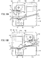
- Print devices 102 and 103 according to modified examples will be described with reference to FIG. 10A and FIG. 10B .
- structural elements corresponding to those of the print device 101 are denoted by the same reference numerals and a description thereof will be omitted, and points that are different from the print device 101 will be mainly described.
- the print device 102 will be described with reference to FIG. 10A .
- the main body case 111 has a substantially square shape in a plan view, and its length in the front-rear direction is shorter in comparison to the structure shown in FIG. 7 to FIG. 9 .
- the case front surface 111B is the same as in the structure shown in FIG. 9 .
- the length in the front-rear direction of the mounting surface 111A is reduced in comparison to the structure shown in FIG. 9 .
- the length in the front-rear direction of the cover 112 (refer to FIG. 7 ) is also reduced corresponding to the mounting surface 111A.
- a front end portion of the case front surface 111B is rotatably supported by a front end portion of the main body case 111.
- the case front surface 111B is configured to be opened and closed with respect to the main body case 111 by the user from above.
- the top surface of the cover 112 and the top surface of the case front surface 111B form the top surface 110A (refer to FIG. 7 ).
- the top surface 110A extends forward and downward from the upper end portion of the rear surface 110B.
- the tube insertion opening 115 is provided in the center of an upper portion of the right surface 110D.
- the tube discharge opening 116 is provided in an upper portion on the front side of the left surface 110C.
- the ribbon mounting portion 130 and the tube printing mechanism 160 are provided in a front left portion of the main body case 111.
- the ribbon mounting portion 130 and the tube printing mechanism 160 are located in front of the tape mounting portion 120 and the tape printing mechanism 150 and below the user interface portion 117.
- the tube mounting portion 140 extends substantially in the left-right direction in front of the tape mounting portion 120 and behind the ribbon mounting portion 130.
- the tube mounting portion 140 is located below the user interface portion 117. In a plan view, the rear right portion of the user interface portion 117 is aligned to the right side of the tape mounting portion 120 and the tape printing mechanism 150, and at least a part of it overlaps with the control board 119 and the power source portion 129.
- the user can attach and detach the tape cassette 80 to and from the tape mounting portion 120 from above.
- the case front surface 111B is opened, the user can attach and detach the ribbon cassette 90 and the tube 9 to and from the ribbon mounting portion 130 and the tube mounting portion 140, respectively, from above.
- the other structural elements are the same as those of the print device 101.
- the tape 8 and the tube 9 are printed and discharged in the same manner as in the print device 101. More specifically, the printed tape 8 and the tube 9 after printing are discharged from the same side surface (namely, the left surface 110C) of the print device 102 in a posture in which their print surfaces are directed forward.
- the print device 103 will be described with reference to FIG. 10B .
- the print device 103 is different from the print device 102 (refer to FIG. 10A ) in the following points.
- the tape discharge opening 114 is provided in an upper portion on the rear side of the right surface 110D.
- the tape mounting portion 120, the tape printing mechanism 150, the control board 119 and the power source portion 129 are respectively left-right inverted with respect to a virtual line that extends in the front-rear direction and that passes through substantially the center of the main body case 111 in a plan view, in comparison to the arrangement of each of them shown in FIG. 10A .
- the feed path 123 extends to the right from the tape mounting portion 120 and connects to the tape discharge opening 114.
- the cover 112 and the user interface portion 117 are respectively left-right inverted with respect to the virtual line that extends in the front-rear direction and that passes through substantially the center of the main body case 111 in a plan view. Therefore, in a plan view, a rear left portion of the user interface portion 117 is aligned to the left side of the tape mounting portion 120 and the tape printing mechanism 150, and at least a part of it overlaps with the control board 119 and the power source portion 129.
- the other structural elements are the same as those of the print device 102.
- the printed tape 8 is discharged rightward from the right surface 110D via the tape discharge opening 114. More specifically, the printed tape 8 and the tube 9 after printing are discharged from different side surfaces (namely, the left surface 110C and the right surface 110D) of the print device 103 in a posture in which their print surfaces are directed forward.
- the tube printing mechanism 160 is provided below the user interface portion 117. At least a part of the tube printing mechanism 160 and at least a part of the user interface portion 117 overlap with each other in the up-down direction. In the present example, the whole of the tube printing mechanism 160 is included in the range of the user interface portion 117 in a plan view. Therefore, the length in the front-rear direction of each of the print devices 102 and 103 is suppressed. Further, an upper portion of the tube printing mechanism 160 overlaps with a front left portion of the user interface portion 117 in a front view. Therefore, the length in the up-down direction of each of the print devices 102 and 103 is suppressed.
- a print device (any one of the print devices 101 to 103) is provided with a first print portion (the tape printing mechanism 150), a first discharge portion (the tape guide 124), a second print portion (the tube printing mechanism 160), a second discharge portion (the tube discharge opening 116), and a user interface portion (the user interface portion 117).
- the first print portion is configured to print on a first medium (the tape 8).
- the first discharge portion is configured to discharge the first medium printed by the first print portion to the outside of the print device.
- the second print portion is configured to print on a second medium (the tube 9).
- the second discharge portion is configured to discharge the second medium printed by the second print portion to the outside of the print device.
- the user interface portion is disposed on a front side portion of the print device.
- the user interface portion includes at least one of a display portion (the display portion 117B) and an operation portion (the operation portion 117A).
- a main scanning direction of the first print portion and a main scanning direction of the second print portion are substantially parallel to the up-down direction.
- a length in the up-down direction of the second print portion is shorter than a length in the up-down direction of the first print portion.
- the second print portion is disposed to the front of the first print portion.
- the user interface portion is disposed in the front side portion of the print device.
- the second print portion whose length in the up-down direction is relatively short, is disposed to the front of the first print portion, whose length in the up-down direction is relatively long. It may be easy to realize the print device having a structure in which the user interface portion and the first print portion do not overlap with each other in the up-down direction. Therefore, it may be possible to suppress the height (the length in the up-down direction) of the print device that is provided with the two printing mechanisms and at least one of the operation portion and the display portion.
- the second print portion is disposed below the user interface portion. At least a part of the second print portion and at least a part of the user interface portion overlap with each other in the up-down direction.
- the second print portion is disposed below the user interface portion such that at least a part of the second print portion and at least a part of the user interface portion overlap with each other in a plan view.
- the user interface portion is disposed to the front of the first print portion such that at least a part of the first print portion and at least a part of the user interface portion overlap with each other in a front view.
- the second print portion and the user interface portion are disposed side by side in the left-right direction when viewed in the up-down direction.
- the second print portion and the user interface portion are disposed side by side in the left-right direction in a plan view.
- At least a part of the second print portion and at least a part of the user interface portion overlap with each other in a front view.
- the print device (any one of the print devices 101 to 103) is provided with a power source portion (the power source portion 129).
- the first print portion and the power source portion are disposed side by side in the left-right direction when viewed in the up-down direction.
- the first print portion and the power source portion are disposed side by side in the left-right direction in a plan view.
- At least a part of the first print portion and at least a part of the power source portion overlap with each other in a side view.
- the print device (any one of the print devices 101 to 103) is provided with a feed portion (the tube mounting portion 140) configured to feed the second medium toward the second print portion.
- the feed portion is disposed to the front of the power source portion.
- the feed portion supplies the second medium to the second print portion using an area in front of the power source portion.
- the feed portion may be possible to suppress the print device from being increased in size.
- the print device (any one of the print devices 101 to 103) is provided with a board (the control board 119).
- the first print portion and the board are disposed side by side in the left-right direction when viewed in the up-down direction.
- the first print portion and the board are disposed side by side in the left-right direction in a plan view.
- the first discharge portion and the second discharge portion are configured to respectively discharge the first medium and the second medium from the same side surface (the left surface 110C) of the print device.
- the first medium and the second medium are discharged from the same side surface of the print device. Therefore, it may be easy for the user to retrieve the first medium and the second medium after printing.
- the first discharge portion and the second discharge portion are configured to respectively discharge the first medium and the second medium from side surfaces (the left surface 110C and the right surface 110D) of the print device that are different from each other.
- the first medium and the second medium are discharged from the different side surfaces of the print device. Therefore, it may be possible to inhibit the first medium and the second medium that have been printed from becoming mixed with each other.
- the first discharge portion is configured to discharge the first medium to the outside of the print device in a state in which a print surface of the first medium printed by the first print portion is directed to the front.
- the second discharge portion is configured to discharge the second medium to the outside of the print device in a state in which a print surface of the second medium printed by the second print portion is directed to the front.
- the user may visually check the print surface of the first medium and the print surface of the second medium simultaneously from the front of the print device.
- the first medium is a tape that is a strip-shaped print medium.
- the second medium is a tube that is a cylindrical print medium.
- the print device may respectively print the two print media having different shapes.
- FIG. 11 A print device 201 according to the third embodiment will be described with reference to FIG. 11 and FIG. 12 .
- tape cassettes 80A and 80B are schematically shown, and tape printing mechanisms 250 and 260 are omitted (this also applies to FIG. 13A , FIG. 15A and FIG. 15B , which will be described later).
- FIG. 12 shows a state in which the tape cassettes 80A and 80B are respectively mounted in tape mounting portions 220 and 230 (this also applies to FIG. 13B , FIG. 14A and FIG. 14B , which will be described later).
- the upper side, the lower side, the lower right side, the upper left side, the upper right side and the lower left side of FIG. 11 are respectively defined as the upper side, the lower side, the right side, the left side, the rear side and the front side of the print device 201.
- the print device 201 is configured to print tapes 8A and 8B (refer to FIG. 12 ) using two printing mechanisms.
- the print device 201 is provided with a housing 210 that includes a main body case 211 and a cover 212.
- the housing 210 has a plurality of side surfaces, namely, a front surface 210A, a rear surface 210B, a left surface 210C and a right surface 210D.
- the housing 210 has a substantially horizontal bottom surface 210E.
- the front surface 210A and the rear surface 210B are side surfaces that face each other in the front-rear direction.
- the left surface 210C and the right surface 210D are side surfaces that face each other in the left-right direction.
- the main body case 211 is a box-shaped member that is long in the left-right direction.
- the top surface of the main body case 211 is a substantially horizontal mounting surface 211A.
- the cover 212 is a member that is configured to be attached to and detached from an upper portion of the main body case 211.
- the cover 212 has a top surface that is long in the left-right direction in a plan view, and four side surfaces (a front surface, a rear surface, a left surface and a right surface) that extend downward from the periphery of the top surface.
- the cover 212 has an inside area that is surrounded by the top surface and the four side surfaces.
- Tape discharge openings 213 and 214 are openings to respectively discharge the tapes 8A and 8B to the outside of the housing 210.
- the tape discharge opening 213 is provided in a right portion of the front surface of the cover 212, and has a rectangular shape that is long in the up-down direction.
- the tape discharge opening 214 is provided in a left portion of the front surface of the cover 212, and has a rectangular shape that is long in the up-down direction.
- the tapes 8A and 8B of the present example have the same length in the width direction (36 mm in the present example). Therefore, the tape discharge openings 213 and 214 have the same opening shape and the same length in the up-down direction.
- the cover 212 When the cover 212 is mounted on the main body case 211 from above, the upper portion of the main body case 211 is housed in the inside area of the cover 212. At this time, the cover 212 covers the mounting surface 211A (refer to FIG. 11 ).
- the tape discharge openings 213 and 214 are disposed on the front side of an upper portion of the front surface of the main body case 211. In other words, the tape discharge openings 213 and 214 are respectively disposed in an upper right portion and an upper left portion of the front surface 210A.
- the mounting surface 211A is provided with the tape mounting portions 220 and 230.
- the tape mounting portions 220 and 230 have a similar structure to the tape mounting portion 20 (refer to FIG. 3 ).
- the tape mounting portion 220 of the present example is provided in the center of a right portion of the mounting surface 211A.
- a feed path 223 extends continuously forward from a front right portion of the tape mounting portion 220.
- the tape mounting portion 230 of the present example is provided in the center of a left portion of the mounting surface 211A.
- a feed path 233 extends continuously forward from a front right portion of the tape mounting portion 230.
- Tape guides 224 and 234 (refer to FIG. 12 ) are respectively provided in the feed paths 223 and 233.
- Each of the tape guides 224 and 234 has a similar structure to the tape guide 24 (refer to FIG. 3 ), and determines the tape discharge direction of each of the tapes 8A and 8B to be the substantially horizontal and forward direction.
- the user can attach and detach the tape cassettes 80A and 80B to and from the tape mounting portions 220 and 230, respectively, from above.
- front end portions of the feed paths 223 and 233 respectively connect to the tape discharge openings 213 and 214.
- a control board 219, a power source portion (not shown in the drawings) and the tape printing mechanisms 250 and 260 will be described with reference to FIG. 12 .
- the control board 219 controls various operations of the print device 201 in the same manner as the control board 19 (refer to FIG. 4 ).
- the power source portion supplies power to the print device 201 in the same manner as the power source portion (not shown in the drawings) of the first embodiment.
- the control board 219 is provided on a rear right portion inside the main body case 211, and extends in the up-down direction and the left-right direction.
- the power source portion is provided on the front side of the control board 219.
- the tape printing mechanism 250 includes a print head 251, a platen holder 252, a platen roller 253, a movable feed roller 254, a tape drive shaft 255, a ribbon take-up shaft 256, a cutter 257, a first drive motor (not shown in the drawings), a cutter motor (not shown in the drawings), a second drive motor (not shown in the drawings) and the like.
- the print head 251, the tape drive shaft 255 and the ribbon take-up shaft 256 are each provided so as to stand upward from the bottom surface of the tape mounting portion 220.
- the print head 251 is provided on the front right portion of the tape mounting portion 220.
- the platen holder 252 is disposed on the right side of the tape mounting portion 220, and is configured to be displaced between an operating position and a retracted position in accordance with the attachment and detachment of the cover 212 (refer to FIG. 11 ).
- the cutter 257 is provided to the rear of the tape guide 224 in the feed path 223.
- the tape printing mechanism 260 has the same structure as the tape printing mechanism 250, and includes a print head 261, a platen holder 262, a platen roller 263, a movable feed roller 264, a tape drive shaft 265, a ribbon take-up shaft 266, a cutter 267, a first drive motor (not shown in the drawings), a cutter motor (not shown in the drawings), a second drive motor (not shown in the drawings) and the like.
- the print head 261, the tape drive shaft 265 and the ribbon take-up shaft 266 are each provided so as to stand upward from the bottom surface of the tape mounting portion 230.
- the print head 261 is provided on the front right portion of the tape mounting portion 230.
- the platen holder 262 is disposed on the right side of the tape mounting portion 230, and is configured to be displaced between an operating position and a retracted position in accordance with the attachment and detachment of the cover 212.
- the cutter 267 is provided to the rear of the tape guide 234 in the feed path 233.
- the tape cassettes 80A and 80B have the same outer shape as the tape cassette 80 (refer to FIG. 4 ), and are configured to be mounted in either of the tape mounting portions 220 and 230.
- the tape cassette 80 that is mounted in the tape mounting portion 220 is referred to as the tape cassette 80A.
- the tape cassette 80 that is mounted in the tape mounting portion 230 is referred to as the tape cassette 80B.
- the tape cassette 80A of the present example is a laminate type tape cassette, and has the same structure as the tape cassette 80 shown in FIG. 4 .
- the tape cassette 80B of the present example is a thermal type tape cassette in which a heat sensitive tape 89 is housed as the tape 8B.
- the first tape roll 81 is rotatably supported inside the tape cassette 80B.
- the first tape roll 81 is the unused heat sensitive tape 89 wound around a spool (not shown in the drawings).
- the tape printing mechanisms 250 and 260 perform printing operations in accordance with control of the control board 219, in a similar manner to the first embodiment. Note, however, that the printing operations of the tape printing mechanisms 250 and 260 are different depending on the type of the tape cassette 80 that is mounted in each of the tape mounting portions 220 and 230.
- the tape printing mechanism 250 performs the printing operations using the laminate type tape cassette 80A. More specifically, the print head 251 of the present example performs mirror image printing, and prints characters on the left surface of the film tape 85 that passes through the right side of the print head 251.
- the created tape 8A passes through the tape guide 224 in the feed path 223, and is discharged from the tape discharge opening 213 in a posture in which the width direction of the tape 8A is substantially parallel to the up-down direction. At this time, the tape 8A is discharged forward from the front surface 210A such that the print surface of the tape 8A is directed rightward. After the tape 8A is cut, the tape 8A falls into a first tape discharge area (not shown in the drawings) located on the front side of the housing 210.
- the tape printing mechanism 260 performs the printing operations using the thermal type tape cassette 80B in the following manner.
- the first drive motor of the tape printing mechanism 260 rotates the tape drive roller 88 by rotating the tape drive shaft 265.
- the heat sensitive tape 89 is pulled out from the first tape roll 81.
- the heat sensitive tape 89 that has been pulled out is fed to a position between the print head 261 and the platen roller 263.
- the print head 261 thermally prints characters on the heat sensitive tape 89 as a normal image.
- the print head 261 of the present example prints the characters on the left surface of the heat sensitive tape 89 that passes through the right side of the print head 261.
- the printed heat sensitive tape 89 is fed to a position between the movable feed roller 264 and the tape drive roller 88. In this manner, the tape 8B, on which the characters have been printed on the heat sensitive tape 89, is created. In the created tape 8B, the characters appear on the print surface of the heat sensitive tape 89.
- the print surface of the heat sensitive tape 89 is the print surface of the tape 8B.
- the tape 8B passes through the inside of the feed path 233 and is fed forward as far as the tape guide 234.
- the second drive motor of the tape printing mechanism 260 drives and rotates the tape guide 234, and further feeds the tape 8B forward.
- the fed tape 8B passes through the tape guide 234, and is discharged from the discharge opening 214 in a posture in which the width direction of the tape 8B is substantially parallel to the up-down direction.
- the tape 8B is discharged forward from the front surface 210A such that the print surface of the tape 8B is directed leftward.
- the respective print surfaces of the discharged tapes 8A and 8B are directed in opposite directions such that they do not face each other.
- the cutter motor of the tape printing mechanism 260 drives the cutter 267, and cuts the tape 8B behind the tape guide 234.
- the cut tape 8B is caused to fly forward from the tape discharge opening 214 by a distance corresponding to a rotation speed of the tape guide 234, and falls into a second tape discharge area (not shown in the drawings) located on the front side of the housing 210.
- the tape guide 224 has the pair of discharge rollers 24A (refer to FIG. 3 ) that is configured to rotate around an axial line that is orthogonal to the bottom surface 210E, and the tape 8A is discharged to the outside by the rotation of the pair of discharge rollers 24A.
- the tape guide 234 has the pair of discharge rollers 24A (refer to FIG. 3 ) that is configured to rotate around the axial line that is orthogonal to the bottom surface 210E, and the tape 8B is discharged to the outside by the rotation of the pair of discharge rollers 24A.
- the axial line of each of the discharge rollers 24A extends in a direction that intersects the bottom surface 210E.
- the tape guide 224 discharges the tape 8A to the outside of the housing 210 in a state in which the print surface of the tape 8A extends in a direction that intersects the bottom surface 210E.
- the tape guide 234 discharges the tape 8B to the outside in a state in which the print surface of the tape 8B extends in a direction that intersects the bottom surface 210E, and a virtual surface including the print surface of the tape 8B intersects a normal line with respect to the print surface of the tape 8A.
- the width of each of the print surfaces of the tapes 8A and 8B extends in the up-down direction, each of the print surfaces extends in a direction that substantially orthogonally intersects the bottom surface 210E that is substantially horizontal.
- the virtual surface including the print surface of the tape 8B extends in the front-rear direction and the up-down direction.
- the normal line with respect to the print surface of the tape 8A is a virtual line that extends in the left-right direction, and substantially orthogonally intersects the virtual surface including the print surface of the tape 8B.
- the manufacturer can change the discharge direction of the tape 8A simply by adjusting the tape guide 224.
- the manufacturer can change the discharge direction of the tape 8B simply by adjusting the tape guide 234.
- the discharge direction of the tape 8A and the discharge direction of the tape 8B are piled up in a common tape discharge area. In this case, the user can easily retrieve the printed tapes 8A and 8B.
- the discharged tapes 8A and 8B are piled up in tape discharge areas that are different from each other. In this case, it is possible to inhibit the printed tapes 8A and 8B from becoming mixed with each other.
- both the tape cassettes 80A and 80B are the laminate type
- the print surfaces of the tapes 8A and 8B that are respectively discharged from the tape discharge openings 213 and 214 are directed in the same direction, namely, to the right.
- the print surfaces of the tapes 8A and 8B that are respectively discharged from the tape discharge openings 213 and 214 are directed in the same direction, namely, to the left.
- the respective print surfaces of the discharged tapes 8A and 8B are directed in opposite directions, such that they face each other.
- the present invention is not limited the structure exemplified by the print device 201 (refer to FIG. 11 and FIG. 12 ), and various modifications are possible.
- Print devices 202 to 207 according to modified examples will be described with reference to FIG. 13A, FIG. 13B , FIG. 14A, FIG 14B , FIG. 15A and FIG. 15B .
- structural elements corresponding to those of the print device 201 are denoted by the same reference numerals and a description thereof will be omitted, and points that are different from the print device 201 will be mainly described.
- the print device 202 will be described with reference to FIG. 13A .
- the tapes 8A and 8B (refer to FIG. 12 ) of the present example have mutually different lengths in the width direction.
- the length in the width direction of the tape 8A is 24 mm
- the length in the width direction of the tape 8B is 48 mm. Therefore, the thickness (the length in the up-down direction) of the tape cassette 80B is larger than the thickness of the tape cassette 80A.
- the length in the up-down direction of the tape mounting portion 230 is larger than the length in the up-down direction of the tape mounting portion 220.
- the main scanning direction of each of the tape printing mechanisms 250 and 260 (refer to FIG. 12 ) of the present example is substantially parallel to the up-down direction.
- the length in the main scanning direction of the tape printing mechanism 250 is at least equal to or more than the length in the width direction of the tape 8A.
- the length in the main scanning direction of the tape printing mechanism 260 is at least equal to or more than the length in the width direction of the tape 8B, and larger than the length in the main scanning direction of the tape printing mechanism 250.
- the length in the up-down direction of the tape discharge opening 213 is reduced corresponding to the tape width of 24 mm.
- the length in the up-down direction of the tape discharge opening 214 is increased corresponding to the tape width of 48 mm. Therefore, the length in the up-down direction of the tape discharge opening 214 is larger than the length in the up-down direction of the tape discharge opening 213.
- the other structural elements are the same as those of the print device 201.
- the print device 202 similarly to the print device 201, the printed tapes 8A and 8B are respectively discharged via the tape discharge openings 213 and 214. Therefore, the print device 202 can respectively print the tapes 8A and 8B having mutually different lengths in the width direction.
- the tape printing mechanism 250 (refer to FIG. 12 ) can appropriately print the tape 8A.
- the tape width of the tape 8B is equal to or less than the length in the main scanning direction of the print head 261 (refer to FIG. 12 )
- the tape printing mechanism 260 (refer to FIG. 12 ) can appropriately print the tape 8B. Therefore, similarly to the print device 201, the print device 202 can also print each of the tapes 8A and 8B having mutually different lengths in the width direction.
- the tape printing mechanism 250 prints the tape 8A having the width of 24 mm.
- the tape printing mechanism 260 prints the tape 8B having the width of 36 mm. This point also applies to the print devices 203 to 207 etc. that will be described later.
- the print device 203 will be described with reference to FIG. 13B .
- the tape mounting portion 220 and the tape printing mechanism 250 are left-right inverted with respect to a virtual line that extends in the front-rear direction and that passes through substantially the center of a right portion of the main body case 211 (refer to FIG. 11 ) in a plan view.
- the feed path 223 (refer to FIG. 11 ) extends forward from a front left portion of the tape mounting portion 220, and connects to the tape discharge opening 213.
- the other structural elements are the same as those of the print device 201.
- the printed tapes 8A and 8B are respectively discharged via the tape discharge openings 213 and 214.
- the print surface of the discharged laminate type tape 8A is directed to the left.
- the print surface of the discharged thermal type tape 8B is directed to the left. That is, the respective print surfaces of the tapes 8A and 8B are directed in the same direction.
- the respective print surfaces of the discharged tapes 8A and 8B are directed in opposite directions such that they face each other.
- both the tape cassettes 80A and 80B are the thermal type
- the respective print surfaces of the discharged tapes 8A and 8B are directed in opposite directions such that they do not face each other.
- the tape cassette 80A is the thermal type and the tape cassette 80B is the laminate type
- the respective print surfaces of the discharged tapes 8A and 8B are directed in the same direction, namely, to the right.
- the print device 204 will be described with reference to FIG. 14A .
- the tape mounting portion 230 and the tape printing mechanism 260 are left-right inverted with respect to a virtual line that extends in the front-rear direction and that passes through substantially the center of a left portion of the main body case 211 in a plan view.
- the feed path 233 (refer to FIG. 11 ) extends forward from a front left portion of the tape mounting portion 230, and connects to the tape discharge opening 214.
- the other structural elements are the same as those of the print device 201.
- the printed tapes 8A and 8B are respectively discharged via the tape discharge openings 213 and 214.
- the print surface of the discharged laminate type tape 8A is directed to the right.
- the print surface of the discharged thermal type tape 8B is directed to the right. That is, the respective print surfaces of the tapes 8A and 8B are directed in the same direction.
- the respective print surfaces of the discharged tapes 8A and 8B are directed in opposite directions such that they do not face each other.
- both the tape cassettes 80A and 80B are the thermal type
- the respective print surfaces of the discharged tapes 8A and 8B are directed in opposite directions such that they face each other.
- the tape cassette 80A is the thermal type and the tape cassette 80B is the laminate type
- the respective print surfaces of the discharged tapes 8A and 8B are directed in the same direction, namely, to the left.
- the print device 205 will be described with reference to FIG. 14B .
- the print device 205 is rotated clockwise by 90 degrees around the substantial center of the housing 210 (refer to FIG. 11 ) in a plan view.
- the housing 210 has a box shape that is long in the front-rear direction.
- the tape discharge opening 213 is provided in a front portion of the left surface 210C.
- the tape mounting portion 220 and the tape printing mechanism 250 are provided in a front portion of the main body case 211.
- the feed path 223 extends to the left from the front left portion of the tape mounting portion 220, and connects to the tape discharge opening 213.
- the tape discharge opening 214 is provided in a rear portion of the left surface 210C.
- the tape mounting portion 230 and the tape printing mechanism 260 are provided in a rear portion of the main body case 211.
- the feed path 233 extends to the left from the front left portion of the tape mounting portion 230, and connects to the tape discharge opening 214.
- the printed tapes 8A and 8B are respectively discharged leftward from the left surface 210C via the tape discharge openings 213 and 214.
- the print surface of the discharged laminate type tape 8A is directed forward.
- the print surface of the discharged thermal type tape 8B is directed rearward. That is, the respective print surfaces of the tapes 8A and 8B are directed in opposite directions such that they do not face each other.
- both the tape cassettes 80A and 80B are the laminate type
- the respective print surfaces of the discharged tapes 8A and 8B are directed in the same direction, namely, to the front.
- the tape cassette 80A is the thermal type and the tape cassette 80B is the laminate type
- the respective print surfaces of the discharged tapes 8A and 8B are directed in opposite directions such that they face each other.
- the print device 206 will be described with reference to FIG. 15A .
- the housing 210 of the present example is provided with a cover (not shown in the drawings) and the main body case 211.
- the tape mounting portions 220 and 230 are provided in the mounting surface 211A.
- the tape discharge openings 213 and 214 of the present example are respectively provided in a right portion and a left portion of the front surface of the main body case 211.
- the feed path 223 extends forward from the tape mounting portion 220, and connects to the tape discharge opening 213.
- the feed path 233 extends forward from the tape mounting portion 230, and connects to the tape discharge opening 214.
- the cover (not shown in the drawings) is provided on the upper side of the main body case 211, and is a plate-shaped member that is configured to open and close the mounting surface 211A.
- the tape printing mechanisms 250 and 260 are provided inside the main body case 211.
- the print device 206 is provided with guide members 270 and 280.
- the guide members 270 and 280 are provided on the front surface 210A, and have a substantially cuboid shape that is long in the up-down direction.
- the guide member 270 is disposed on the right side of the tape discharge opening 213 in a front view, and has a guide surface 270A.
- the guide surface 270A is a vertical plane that extends leftward and forward from the vicinity of a right end portion of the tape discharge opening 213.
- the guide member 280 is disposed on the left side of the tape discharge opening 214 in the front view, and has a guide surface 280A.
- the guide surface 280A is a vertical plane that extends rightward and forward from the vicinity of a left end portion of the tape discharge opening 214.
- the other structural elements are the same as those of the print device 201.
- the tape guide 224 discharges the printed tape 8A forward from the tape discharge opening 213.
- the discharged tape 8A is guided leftward and forward along the guide surface 270A.
- the tape 8A falls into a tape discharge area (not shown in the drawings) located in front of the center of the housing 210.
- the tape guide 234 discharges the printed tape 8B forward from the tape discharge opening 214.
- the discharged tape 8B is guided rightward and forward along the guide surface 280A. After the tape 8B is cut, the tape 8B falls into the tape discharge area (not shown in the drawings) in the same manner as the tape 8A.
- the printed tapes 8A and 8B are respectively guided along the guide surfaces 270A and 280A, and are piled up in the common tape discharge area. Therefore, it is easy for the user to retrieve the printed tapes 8A and 8B. It is preferable that the tape discharge area be located between the guide members 270 and 280. It is thus possible to reliably inhibit the printed tapes 8A and 8B from being dispersed outside the housing 210.
- the print device 207 will be described with reference to FIG. 15B .
- the print device 207 is different in the following points.
- the print device 207 is provided with a guide member 290 in place of the guide members 270 and 280 (refer to FIG. 15A ).
- the guide member 290 is provided on the front surface 210A, and has a substantially cuboid shape that is long in the up-down direction.
- the guide member 290 is disposed between the tape discharge openings 213 and 214 in a front view.
- the guide member 290 has guide surfaces 290A and 290B.
- the guide surface 290A is a vertical plane that extends rightward and forward from the vicinity of a left end portion of the tape discharge opening 213.
- the guide surface 290B is a vertical plane that extends leftward and forward from the vicinity of a right end portion of the tape discharge opening 214.
- the other structural elements are the same as those of the print device 206.
- the tape guide 224 discharges the printed tape 8A forward from the tape discharge opening 213.
- the discharged tape 8A is guided rightward and forward along the guide surface 290A.
- the tape 8A falls into a first tape discharge area (not shown in the drawings) located on the right side or to the front right of the guide member 290.
- the tape guide 234 discharges the printed tape 8B forward from the tape discharge opening 214.
- the discharged tape 8B is guided leftward and forward along the guide surface 290B.
- the tape 8B falls into a second tape discharge area located on the left side or to the front left of the guide member 290.
- the printed tape 8A is guided into the first tape discharge area along the guide surface 290A. It is thus possible to inhibit the printed tape 8A from being dispersed outside the housing 210.
- the printed tape 8B is guided into the second tape discharge area along the guide surface 290B. It is thus possible to inhibit the printed tape 8B from being dispersed outside the housing 210. It is thus possible to inhibit the printed tapes 8A and 8B from becoming mixed outside the housing 210.
- the first tape discharge area and the second tape discharge area be located on either side of the guide member 290. It is thus possible to reliably inhibit the printed tapes 8A and 8B from becoming mixed outside the housing 210.
- the guide surface 290A may be a vertical plane that extends forward, or leftward and forward, from the vicinity of the left end portion of the tape discharge opening 213.
- the guide surface 290B may be a vertical plane that extends forward, or rightward and forward, from the vicinity of the right end portion of the tape discharge opening 214. That is, the shape and size of the guide member 290 can be changed as long as the guide member 290 can be disposed between the first tape discharge area and the second tape discharge area.
- a print device (any one of the print devices 201 to 207) is provided with a first print portion (the tape printing mechanism 250), a first discharge portion (the tape guide 224), a second print portion (the tape printing mechanism 260), and a second discharge portion (the tape guide 234).
- the first print portion is configured to print on a first surface, which is a surface of a first medium (the tape 8A).
- the first discharge portion is configured to discharge the first medium whose first surface has been printed by the first print portion to the outside of the print device.
- the second print portion is configured to print on a second surface, which is a surface of a second medium (the tape 8B).
- the second discharge portion is configured to discharge the second medium whose second surface has been printed by the second print portion to the outside of the print device.
- the first discharge portion has a first discharge roller (at least one of the discharge rollers 24A of the tape guide 224) configured to rotate around an axial line that extends in a direction that intersects a bottom surface (the bottom surface 210E).
- the first discharge portion is configured to discharge the first medium to the outside of the print device by the rotation of the first discharge roller.
- the second discharge portion has a second discharge roller (at least one of the discharge rollers 24A of the tape guide 234) configured to rotate around an axial line that extends in a direction that intersects the bottom surface.
- the second discharge portion is configured to discharge the second medium to the outside of the print device by the rotation of the second discharge roller.
- the first medium and the second medium are discharged from the print device such that their print surfaces intersect the bottom surface and at least in a posture in which they are not orthogonal to each other.
- the first discharge portion and the second discharge portion it may be possible to easily change the directions in which the first medium and the second medium are respectively discharged. Therefore, it may be possible to easily change the directions in which the print media are respectively discharged from the two printing mechanisms, without increasing the size of the print device.
- the first discharge portion and the second discharge portion are configured to respectively discharge the first medium and the second medium from a front surface (the front surface 210A) of the print device.
- a user on the front surface side of the print device may easily retrieve the first medium and the second medium that have been printed. Therefore, the operability of the print device may be increased.
- each of the first medium and the second medium is a tape that is a strip-shaped print medium.
- two tapes may be respectively printed by different printing mechanisms.
- usability of the print device may be improved.
- the length in a main scanning direction of the first print portion and the length in a main scanning direction of the second print portion are different from each other.
- two tapes having different tape widths may be respectively printed by different printing mechanisms.
- the usability of the print device may be improved.
- the first medium is a tape (the laminate type tape 8A) that is a strip-shaped print medium on which printing is performed using an ink ribbon.
- the second medium is a roll of paper (the thermal type tape 8B) that is a strip-shaped print medium on which thermal printing is performed.
- two tapes used in different printing methods may be respectively printed by different printing mechanisms.
- the usability of the print device may be improved.
- the first discharge portion and the second discharge portion are configured to respectively discharge the first medium and the second medium from a left side surface (the left surface 210C) of the print device.
- the user on the front surface side of the print device may easily retrieve the first print medium and the second print medium that have been printed. Therefore, operability of the print device may be improved.
- the first discharge portion is configured to discharge the first medium to the outside of the print device in a state in which the first surface faces a predetermined direction.
- the second discharge portion is configured to discharge the second medium to the outside of the print device in a state in which the second surface faces the predetermined direction.
- the first medium and the second medium that have been printed are discharged such that the first surface and the second surface are directed in the same direction. Since the user may visually check the first surface and the second surface simultaneously from the same side, the operability of the print device may be improved.
- the first discharge portion is configured to discharge the first medium to the outside of the print device, in a state in which the first surface faces a predetermined direction.
- the second discharge portion is disposed on the predetermined direction side of the first discharge portion.
- the second discharge portion is configured to discharge the second medium to the outside of the print device in a state in which the second surface faces a direction opposite to the predetermined direction.
- the first medium and the second medium that have been printed are discharged such that the first surface and the second surface are directed in the opposite directions.
- the user may visually check the first surface and the second surface simultaneously, from a position between the first medium and the second medium that have been printed.
- the print device (any one of the print devices 201 to 207) is provided with a main body portion (the main body case 211) and a cover (the cover 212).
- a first mounting portion (the tape mounting portion 220) and a second mounting portion (the tape mounting portion 230) are disposed in the main body portion.
- the first mounting portion is configured such that the first medium is detachably mounted in the first mounting portion.
- the second mounting portion is configured such that the second medium is detachably mounted in the second mounting portion.
- the cover is configured to be displaced between a positon in which the cover open a top surface (the mounting surface 211A) of the main body portion and a positon in which the cover close the top surface of the main body portion.
- the first mounting portion and the second mounting portion have attaching openings via which the first medium and the second medium are respectively attachable and detachable from above in a state in which the top surface of the main body portion is opened by the cover.
- the first medium and the second medium may be respectively attached to and detached from the first mounting portion and the second mounting portion from above. Therefore, the operability of the print device may be improved.
- the print device (any one of the print devices 201 to 207) is provided with a first print portion (the tape printing mechanism 250), a first discharge portion (the tape guide 224), a second print portion (the tape printing mechanism 260) and a second discharge portion (the tape guide 234).
- the first print portion is configured to print on a first surface, which is a surface of a first medium (the tape 8A).
- the first discharge portion is configured to discharge the first medium whose first surface has been printed by the first print portion to the outside of the print device.
- the second print portion is configured to print on a second surface, which is a surface of a second medium (the tape 8B).
- the second discharge portion is configured to discharge the second medium whose second surface has been printed by the second print portion to the outside of the print device.
- the first discharge portion is configured to discharge the first medium to the outside of the print device in a state in which a virtual plane including the first surface intersects a bottom surface (the bottom surface 210E) of the print device.
- the second discharge portion is configured to discharge the second medium to the outside of the print device in a state in which a virtual plane including the second surface intersects the bottom surface and a normal line with respect to the first surface.
- the first medium and the second medium are discharged from the print device such that their print surfaces intersect the bottom surface and at least in a posture in which they are not orthogonal to each other.
- the first discharge portion and the second discharge portion it may be possible to easily change the directions in which the first medium and the second medium are respectively discharged. Therefore, it may be possible to easily change the directions in which the print media are respectively discharged from the two printing mechanisms, without increasing the size of the print device.
- a print device may be structured by appropriately combining the features of each of the print devices disclosed in the first to third embodiments.
- a new tape mounting portion and a new tape printing mechanism may be provided below the user interface portion 117, in place of the ribbon mounting portion 130, the tube mounting portion 140 and the tube printing mechanism 160.
- the length in the main scanning direction of the new tape printing mechanism be shorter than the length in the main scanning direction of the tape printing mechanism 150.
- the guide members 270 and 280 may be provided adjacent to the tape discharge opening 114 and the tube discharge opening 116, respectively.
- the guide member 290 (refer to FIG. 15B ) may be provided between the tape discharge opening 114 and the tube discharge opening 116. It is thus possible to freely adjust the areas into which the tape and the tube are respectively discharged.
- the tape guide 24 is not limited to a guide having the pair of discharge rollers 24A (this also applies to the tape guides 124, 224 and 234).
- the tape guide 24 shown in FIG. 16 has a pair of guide plates 24B that are disposed so as to face each other in the left-right direction. A gap through which the tape 8 (refer to FIG. 2 ) can pass is formed between the pair of guide plates 24B.
- the tape discharge direction is determined by the arrangement and angle of the pair of guide plates 24B.
- the tape discharge direction is also the substantially horizontal and forward direction. The user can manually adjust at least one of the arrangement and the angle of the pair of guide plates 24B. Therefore, the user can freely change the tape discharge direction by adjusting the pair of guide plates 24B.
- the tape guide 24 may have the single discharge roller 24A.
- the discharge roller 24A may feed the tape 8 by rotating while the tape 8 is clamped between it and a side wall of the feed path 23.
- the tape guide 24 may have the single guide plate 24B.
- the guide plate 24B may guide the tape 8 between it and the side wall of the feed path 23.
- a guide member (for example, a discharge roller, a guide plate or the like) to discharge the tube 9 may be provided in the vicinity of each of the tube discharge openings 16 and 116.
- the various functions disclosed in the first to third embodiments also apply to other print devices having at least one of the structures that provides at least one of the various functions.
- the print device 103 has the structures and functions similar to those described in (1-3-1).
- the tape discharge direction is changed by adjusting the tape guide, it may be possible to provide functions similar to those described in (1-3-1).
Landscapes
- Printers Characterized By Their Purpose (AREA)
- Handling Of Continuous Sheets Of Paper (AREA)
- Feeding Of Articles By Means Other Than Belts Or Rollers (AREA)
Description
- The present invention relates to a print device that is provided with a plurality of printing mechanisms.
- In related art, a print device is known that is provided with a plurality of printing mechanisms. For example, each of known print devices disclosed in Japanese Unexamined Patent Application Publication (Translation of
PCT Application) No. 2001-509102 2006-116969 PCT Application) No. 2001-509102 2006-116969 JP H11 286129 A - With the above-described known technology, there is a possibility that the print media respectively discharged from the two discharge openings become mixed with each other at the front of the print device. In order to avoid this, it is conceivable to change the arrangement or structure of the two printing mechanisms such that the print media are discharged in different directions from the two printing mechanisms. In this case, there is a possibility that the size of the print device increases in accordance with the change in the arrangement or structure of the two printing mechanisms.
- It is an object of the present invention to inhibit print media respectively discharged from two printing mechanisms from becoming mixed, without increasing a size of a print device.
- A print device according to an aspect of the present invention as defined in appended
claim 1. - According to the print device of the present aspect, the first discharge portion and the second discharge portion discharge the first medium and the second medium in directions that separate from each other, from positions that do not overlap with each other in the up-down direction. The discharged first medium and the discharged second medium are unlikely to be mixed with each other outside the print device. Therefore, it may be possible to inhibit the print media respectively discharged from the two printing mechanisms from becoming mixed, without increasing the size of the print device.
- Further embodiments are disclosed in dependent claims 2-7.
- Embodiments of the present disclosure will be described below in detail with reference to the accompanying drawings in which:
-
FIG. 1 is a perspective view of aprint device 1 as viewed from the upper right front side; -
FIG. 2 is a perspective view of theprint device 1 as viewed from the upper left front side; -
FIG. 3 is a perspective view of amain body case 11 as viewed from the upper front side; -
FIG. 4 is a plan view schematically showing an internal structure of theprint device 1; -
FIG. 5A to FIG. 5C are plan views respectively, schematically showing internal structures of print devices 2 to 4; -
FIG. 6A to FIG. 6C are plan views respectively, schematically showing internal structures of print devices 5 to 7; -
FIG. 7 is a perspective view of aprint device 101 as viewed from the upper right front side; -
FIG. 8 is a perspective view of amain body case 111 as viewed from the upper right front side; -
FIG. 9 is a plan view schematically showing an internal structure of theprint device 101; -
FIG. 10A and FIG. 10B are plan views respectively, schematically showing internal structures ofprint devices -
FIG. 11 is a perspective view of aprint device 201 as viewed from the upper right front side; -
FIG. 12 is a plan view schematically showing an internal structure of theprint device 201; -
FIG. 13A is a perspective view of aprint device 202 as viewed from the upper right front side, andFIG. 13B is a plan view schematically showing an internal structure of aprint device 203; -
FIG. 14A and FIG. 14B are plan views respectively, schematically showing internal structures ofprint devices -
FIG. 15A and FIG. 15B are perspective views ofprint devices -
FIG. 16 is a perspective view of themain body case 11 according to a modified example, as viewed from the upper front side. - A first embodiment of the present invention will be described with reference to the drawings. A
print device 1 according to the first embodiment will be described with reference toFIG. 1 to FIG. 4 . InFIG. 3 , atape cassette 80 and aribbon cassette 90 are schematically shown, and atape printing mechanism 50 and atube printing mechanism 60 are omitted.FIG. 4 shows a state in which thetape cassette 80, theribbon cassette 90 and atube 9 are respectively mounted in atape mounting portion 20, aribbon mounting portion 30 and a tube mounting portion 40 (this also applies toFIG. 5A to FIG. 5C andFIG. 6A to 6C , which will be described later). In the description below, the upper side, the lower side, the lower right side, the upper left side, the upper right side and the lower left side ofFIG. 1 are respectively defined as the upper side, the lower side, the right side, the left side, the rear side and the front side of theprint device 1. - As shown in
FIG. 1 andFIG. 2 , theprint device 1 is configured to print atape 8, which is a strip-shaped print medium, and thetube 9, which is a cylindrical print medium, using the two printing mechanisms, respectively. Theprint device 1 is provided with ahousing 10 that includes amain body case 11 and acover 12. Thehousing 10 has a plurality of side surfaces, namely, afront surface 10A and arear surface 10B that face each other in the front-rear direction, and aleft surface 10C and aright surface 10D that face each other in the left-right direction. - The
main body case 11 is a cuboid box-shaped member that is long in the left-right direction. Thecover 12 is a plate-shaped member, and is disposed on the upper side of themain body case 11. A rear end portion of thecover 12 is rotatably supported by the upper side of a rear end portion of themain body case 11. Alock mechanism 13 is provided on the upper side of a front end portion of themain body case 11. Thelock mechanism 13 locks a front end portion of thecover 12 that is closed with respect to themain body case 11, and restricts the opening of thecover 12. - When the
cover 12 is closed with respect to the main body case 11 (refer toFIG. 1 andFIG. 2 ), thecover 12 covers a mountingsurface 11A (refer toFIG. 3 ). The mountingsurface 11A is a top surface of themain body case 11. When a user opens thecover 12, the user operates thelock mechanism 13 to release the locking of thecover 12, and causes thecover 12 to pivot upward from thelock mechanism 13. When thecover 12 is opened with respect to themain body case 11, the mountingsurface 11A is exposed in the upward direction. - A
tape discharge opening 14, atube insertion opening 15, atube discharge opening 16, auser interface portion 17 and ahandle portion 18 are provided on the side surfaces of thehousing 10. In the present example, thefront surface 10A, therear surface 10B, theleft surface 10C and theright surface 10D substantially correspond to the front surface, the rear surface, the left surface and the right surface of themain body case 11. Thetape discharge opening 14 is an opening to discharge thetape 8 to the outside of thehousing 10. Thetape discharge opening 14 is provided in an upper right portion of thefront surface 10A, and has a rectangular shape that is long in the up-down direction. - The
tube insertion opening 15 is an opening to guide thetube 9 to the inside of thehousing 10. Thetube insertion opening 15 is provided in an upper portion on the rear side of theright surface 10D, and has a rectangular shape that is slightly longer in the up-down direction. Thetube discharge opening 16 is an opening to discharge thetube 9 to the outside of thehousing 10. Thetube discharge opening 16 is provided in an upper portion on the rear side of theleft surface 10C, and has a rectangular shape that is slightly longer in the up-down direction. Thetube discharge opening 16 is located slightly to the front of thetube insertion opening 15. The direction in which thetube 9 is discharged from theprint device 1 is referred to as a tube discharge direction. The tube discharge direction is determined by an orientation of thetube discharge opening 16. Therefore, a manufacturer can change the tube discharge direction by a design change of the orientation of thetube discharge opening 16. In the present example, since thetube discharge opening 16 is directed leftward and substantially horizontally, the tube discharge direction is also a substantially horizontal and leftward direction. - The
user interface portion 17 includes a display portion and an operation portion. In the present example, the display portion is a plurality of LEDs that indicate an operation state of theprint device 1. The operation portion is a plurality of operation buttons including a power button and a start button. Theuser interface portion 17 is provided on thefront surface 10A, to the right of thetape discharge opening 14. Thehandle portion 18 is a member that is gripped when the user carries theprint device 1. Thehandle portion 18 is provided as a bridge between theleft surface 10C and theright surface 10D, and can rotate to the front side and to the rear side while passing above themain body case 11. - As shown in
FIG. 3 , thetape mounting portion 20, theribbon mounting portion 30, thetube mounting portion 40 and the like are provided in the mountingsurface 11A. Thetape mounting portion 20 is a portion which thetape cassette 80 can be attached to and detached from. Thetape mounting portion 20 is a recessed portion that is open upward, and is formed in an open shape substantially corresponding to thetape cassette 80 in a plan view. Thetape mounting portion 20 of the present example is provided in a right portion of the mountingsurface 11A and in front of thetube mounting portion 40. - A
relief portion 21 is a portion that is recessed forward from a front left portion of thetape mounting portion 20. Arelief portion 22 is a portion that is recessed rearward from a rear right portion of thetape mounting portion 20. In a state in which the cover 12 (refer toFIG. 1 ) is open, the user can attach and detach thetape cassette 80 to and from thetape mounting portion 20 from above. At this time, the user can easily attach and detach thetape cassette 80 to and from thetape mounting portion 20, by inserting his/her fingers that are gripping thetape cassette 80 into therelief portions tape cassette 80 is mounted in thetape mounting portion 20, the width direction of various tapes and of an ink ribbon housed in thetape cassette 80 is substantially parallel to the up-down direction. - A
feed path 23 is a groove portion that extends continuously forward from a front right portion of thetape mounting portion 20. A front end portion of thefeed path 23 is connected to thetape discharge opening 14. Atape guide 24 is provided in thefeed path 23, on the rear side of thetape discharge opening 14. Thetape guide 24 has a pair ofdischarge rollers 24A that are disposed to face each other in the left-right direction. Each of thedischarge rollers 24A is a rotating body that is configured to rotate around an axial line that is orthogonal to the bottom surface of thehousing 10. A gap through which the tape 8 (refer toFIG. 2 ) can pass is formed between the pair ofdischarge rollers 24A. - The direction in which the
tape 8 is discharged from theprint device 1 is referred to as a tape discharge direction. The tape discharge direction is determined by the direction in which the pair ofdischarge rollers 24A feed thetape 8. Therefore, the manufacturer can change the tape discharge direction by a design change of the direction in which the pair ofdischarge rollers 24A feed thetape 8. In thetape guide 24 of the present example, the pair ofdischarge rollers 24A rotate while clamping thetape 8 between them, and thus thetape 8 is fed forward and substantially horizontally. Therefore, the tape discharge direction is also a substantially horizontal and forward direction. - The
ribbon mounting portion 30 is a portion which theribbon cassette 90 can be attached to and detached from. Theribbon mounting portion 30 is a recessed portion that is open upward, and is formed in an open shape substantially corresponding to theribbon cassette 90 in a plan view. Theribbon mounting portion 30 of the present example is provided in a left portion of the mountingsurface 11A and in front of thetube mounting portion 40. In other words, thetape mounting portion 20 and theribbon mounting portion 30 are disposed along a tube feed direction that will be described later, such that they are arranged side by side in the left-right direction. In the present example, substantially the whole of thetape mounting portion 20 overlaps with substantially the whole of theribbon mounting portion 30 in the left-right direction. - A
relief portion 31 is a portion that is recessed rightward from a front right portion of theribbon mounting portion 30. Arelief portion 32 is a portion that is recessed leftward from a front left portion of theribbon mounting portion 30. In a state in which thecover 12 is open, the user can attach and detach theribbon cassette 90 to and from theribbon mounting portion 30 from above. At this time, the user can easily attach and detach theribbon cassette 90 to and from theribbon mounting portion 30, by inserting his/her fingers that are gripping theribbon cassette 90 into therelief portions - The
tube mounting portion 40 is a portion which the tube 9 (refer toFIG. 2 ) can be attached to and detached from. Thetube mounting portion 40 is a groove portion that is open upward, and extends from thetube insertion opening 15 to thetube discharge opening 16. Since thetube discharge opening 16 is located slightly to the front of thetube insertion opening 15, thetube mounting portion 40 is slightly inclined toward the front left side and extends substantially in the left-right direction. The direction in which thetube mounting portion 40 extends from thetube insertion opening 15 toward thetube discharge opening 16 is referred to as the tube feed direction. A cross section of the opening of thetube mounting portion 40 that is orthogonal to the tube feed direction is slightly larger than a cross section (namely, a transverse section of the tube 9) that is orthogonal to the extending direction of thetube 9, except a section where thetube mounting portion 40 and theribbon mounting portion 30 are connected spatially. - A rear end portion of the
relief portion 22 is connected spatially to thetube mounting portion 40 on the left side of thetube insertion opening 15. A rear end portion of theribbon mounting portion 30 is connected spatially to thetube mounting portion 40 on the right side of thetube discharge opening 16. In a state in which thecover 12 is open, the user can attach and detach thetube 9 to and from thetube mounting portion 40 from above. At this time, the user can easily attach and detach thetube 9 to and from thetube mounting portion 40, by inserting his/her fingers that are gripping thetube 9 into at least one of therelief portion 22 and theribbon mounting portion 30. The user mounts thetube 9 in thetube mounting portion 40 along the tube feed direction such that thetube 9 extends from thetube insertion opening 15 to thetube discharge opening 16. - A
control board 19, a power source portion (not shown in the drawings), thetape printing mechanism 50, thetube printing mechanism 60, thetape cassette 80 and theribbon cassette 90 will be described with reference toFIG. 4 . Thecontrol board 19 is a board on which a CPU, a ROM, a RAM, a CGROM and the like (which are not shown in the drawings) are provided, and controls various operations of theprint device 1. For example, thecontrol board 19 controls a printing operation of each of thetape printing mechanism 50 and thetube printing mechanism 60. Thecontrol board 19 of the present example is provided on a rear right portion inside the main body case 11 (refer toFIG. 3 ), and extends in the up-down direction and the left-right direction. The power source portion is connected to a battery (not shown in the drawings) that is mounted in themain body case 11, or is connected to an external power source (not shown in the drawings) via a cord, and supplies power to theprint device 1. The power source portion of the present example is provided on the front side of thecontrol board 19. - The
tape cassette 80 is a box-shaped body that is configured to house at least thetape 8. Thetape cassette 80 of the present example is a laminate type tape cassette that houses afilm tape 85 and a double-sidedadhesive tape 87, as thetape 8, and also houses anink ribbon 86. Afirst tape roll 81, aribbon roll 82, a ribbon take-upspool 83, asecond tape roll 84 and atape drive roller 88 are each rotatably supported inside thetape cassette 80. - The
first tape roll 81 is theunused film tape 85 wound around a spool (not shown in the drawings). Theribbon roll 82 is theunused ink ribbon 86 wound around a spool (not shown in the drawings). The ribbon take-upspool 83 is a spool around which the usedink ribbon 86 is wound. Thesecond tape roll 84 is the unused double-sidedadhesive tape 87 wound around a spool (not shown in the drawings). Thetape drive roller 88 is a roller to feed thetape 8. - The
tape printing mechanism 50 includes aprint head 51, aplaten holder 52, aplaten roller 53, amovable feed roller 54, atape drive shaft 55, a ribbon take-upshaft 56, acutter 57, a first drive motor (not shown in the drawings), a cutter motor (not shown in the drawings), a second drive motor (not shown in the drawings) and the like. Theprint head 51, thetape drive shaft 55 and the ribbon take-upspool 56 are each provided so as to stand upward from the bottom surface of thetape mounting portion 20. Theprint head 51 is a thermal head that includes a heating body (not shown in the drawings), and is provided on the front right portion of thetape mounting portion 20. Thetape drive shaft 55 is a shaft that can rotate thetape drive roller 88. The ribbon take-upshaft 56 is a shaft that is configured to rotate the ribbon take-upspool 83. The first drive motor (not shown in the drawings) is a motor that drives and rotates thetape drive shaft 55 and the ribbon take-upshaft 56. - The
platen roller 53 is a roller that is configured to rotate relative to theprint head 51. Themovable feed roller 54 is a roller that is configured to rotate relative to thetape drive shaft 55. Theplaten roller 53 and themovable feed roller 54 are rotatably supported at the leading end of theplaten holder 52. Theplaten holder 52 is disposed on the right side of thetape mounting portion 20, and is configured to be displaced between an operating position and a retracted position in accordance with the opening and closing of the cover 12 (refer toFIG. 1 ). When theplaten holder 52 is in the operating position, theplaten roller 53 and themovable feed roller 54 are disposed on the inside of thetape mounting portion 20. When theplaten holder 52 is in the retracted position, theplaten roller 53 and themovable feed roller 54 are disposed on the outside of thetape mounting portion 20. Thecutter 57 is provided to the rear of thetape guide 24, and is configured to cut thetape 8 on thefeed path 23. The cutter motor (not shown in the drawings) is a motor that drives thecutter 57. The second drive motor (not shown in the drawings) is a motor that drives and rotates thetape guide 24. - When the cover 12 (refer to
FIG. 1 ) is opened, theplaten holder 52 is displaced to the retracted position. When thetape cassette 80 is mounted in thetape mounting portion 20, thetape drive shaft 55 and the ribbon take-upshaft 56 are respectively inserted into thetape drive roller 88 and the ribbon take-upspool 83. After that, when thecover 12 is closed, theplaten holder 52 is displaced to the operating position. Theplaten roller 53 causes theunused film tape 85 and theunused ink ribbon 86 to be superimposed with each other, and urges them toward theprint head 51. The printedfilm tape 85 and the unused double-sidedadhesive tape 87 are clamped between themovable feed roller 54 and thetape drive roller 88. - The
tape printing mechanism 50 performs the following printing operations in accordance with control of thecontrol board 19. The first drive motor of thetape printing mechanism 50 rotates thetape drive shaft 55 and the ribbon take-upshaft 56, and thereby rotates thetape drive roller 88 and the ribbon take-upspool 83. In accordance with the rotation of thetape drive roller 88, thefilm tape 85 is pulled out from thefirst tape roll 81, and the double-sidedadhesive tape 87 is pulled out from thesecond tape roll 84. In accordance with the rotation of the ribbon take-upspool 83, theink ribbon 86 is pulled out from theribbon roll 82. Thefilm tape 85 and theink ribbon 86 that have been pulled out are fed to a position between theprint head 51 and theplaten roller 53. - Using the
ink ribbon 86, theprint head 51 performs mirror image printing and prints characters on thefilm tape 85. Theprint head 51 of the present example prints characters on the left surface of thefilm tape 85 that passes through the right side of theprint head 51. The usedink ribbon 86 is taken up by the ribbon take-upspool 83. The printedfilm tape 85 is fed to a position between themovable feed roller 54 and thetape drive roller 88, and the pulled out double-sidedadhesive tape 87 is adhered to the printedfilm tape 85. In this manner, thetape 8 obtained by adhering the double-sidedadhesive tape 87 to a print surface of thefilm tape 85 is created. In the createdtape 8, the characters appear on a surface on the opposite side to the print surface of thefilm tape 85. Hereinafter, of both the surfaces of thetape 8, the surface on which the characters appear (in the present example, the surface to which the double-sidedadhesive tape 87 is not adhered) is referred to as a print surface of thetape 8. - Further, the
tape 8 passes through the inside of thefeed path 23, and is fed forward as far as thetape guide 24. The second drive motor of thetape printing mechanism 50 rotates and drives thetape guide 24, and further feeds thetape 8 forward. The fedtape 8 is discharged from the tape discharge opening 14 in a posture in which the width direction of thetape 8 is substantially parallel to the up-down direction. At this time, thetape 8 is discharged forward from thefront surface 10A such that the print surface of thetape 8 is directed rightward. The cutter motor of thetape printing mechanism 50 drives thecutter 57, and cuts thetape 8 behind thetape guide 24. The cut tape 8 (a so-called label) is caused to fly forward from the tape discharge opening 14 by a distance corresponding to a rotation speed of the tape guide 24 (more specifically, the pair ofdischarge rollers 24A), and falls into a first discharge area (not shown in the drawings). The first discharge area is an area in which thetape 8 discharged by thetape guide 24 is arranged outside thehousing 10. - The
ribbon cassette 90 is a box-shaped body that is configured to house anink ribbon 93. Aribbon roll 91 and a ribbon take-upspool 92 are each rotatably supported inside theribbon cassette 90. Theribbon roll 91 is theunused ink ribbon 93 wound around a spool (not shown in the drawings). The ribbon take-upspool 92 is a spool around which the usedink ribbon 93 is wound. - The
tube printing mechanism 60 includes aprint head 61, amovable feed roller 62, a ribbon take-upshaft 63, acutter 64, a cuttingboard 65, a drive motor (not shown in the drawings), a cutter motor (not shown in the drawings) and the like. Theprint head 61 and the ribbon take-upshaft 63 are each provided so as to stand upward from the bottom surface of theribbon mounting portion 30. Theprint head 61 is a thermal head that includes a heating body (not shown in the drawings), and is provided on a rear portion of theribbon mounting portion 30. The ribbon take-upshaft 63 is a shaft that is configured to rotate the ribbon take-upspool 92. - The
movable feed roller 62 is a roller that is configured to rotate relative to theprint head 61. Themovable feed roller 62 is disposed on the rear side of theribbon mounting portion 30, and is configured to be displaced between an operating position and a retracted position in accordance with the opening and closing of the cover 12 (refer toFIG. 1 ). When themovable feed roller 62 is in the operating position, themovable feed roller 62 is disposed on the inside of thetube mounting portion 40 and comes close to theprint head 61. When themovable feed roller 62 is in the retracted position, themovable feed roller 62 is disposed on the rear side of thetube mounting portion 40, and is separated from theprint head 61. The drive motor (not shown in the drawings) is a motor that drives and rotates themovable feed roller 62 and the ribbon take-upshaft 63. - The
cutter 64 and the cuttingboard 65 are provided on the upstream side in the tube feed direction relative to thetube discharge opening 16, and on the downstream side in the tube feed direction relative to theribbon mounting portion 30. Thecutter 64 and the cuttingboard 65 are provided so as to face each other, with thetube mounting portion 40 interposed therebetween. By thecutter 64 moving toward the cuttingboard 65, thecutter 64 can press thetube 9 located in thetube mounting portion 40 against the cuttingboard 65 and can cut thetube 9. The cutter motor (not shown in the drawings) is a motor that drives thecutter 64. - When the
cover 12 is opened, themovable feed roller 62 is displaced to the retracted position. When theribbon cassette 90 is mounted in theribbon mounting portion 30, the ribbon take-upshaft 63 is inserted into the ribbon take-upspool 92. After that, when thecover 12 is closed, themovable feed roller 62 is displaced to the operating position. Themovable feed roller 62 causes thetube 9 located in thetube mounting portion 40 and theunused ink ribbon 93 to be superimposed with each other, and urges them toward theprint head 61. At this time, thetube 9 is elastically deformed by the urging force of themovable feed roller 62, and comes into surface-contact with theprint head 61 via theink ribbon 93. - The
tube printing mechanism 60 performs the following printing operations in accordance with the control of thecontrol board 19. The drive motor of thetube printing mechanism 60 rotates themovable feed roller 62 and the ribbon take-upshaft 63. In accordance with the rotation of themovable feed roller 62, thetube 9 located in thetube mounting portion 40 is fed to the downstream side in the tube feed direction. At this time, thetube 9 before printing that is located outside thehousing 10 is drawn into the inside of thetube mounting portion 40 from theright surface 10D via thetube insertion opening 15. The ribbon take-upspool 92 rotates in accordance with the rotation of the ribbon take-upshaft 63, and thus theink ribbon 93 is pulled out from theribbon roll 91. - Using the
ink ribbon 93 that has been pulled out, theprint head 61 prints characters on thetube 9 that is being fed. Theprint head 61 of the present example performs normal image printing and prints the characters on the front surface of thetube 9 that passes through the rear side of theprint head 61. Therefore, the front surface of thetube 9 is the print surface of thetube 9. The usedink ribbon 93 is taken up by the ribbon take-upspool 92. Thetube 9 after printing is fed from themovable feed roller 62 to the downstream side in the tube feed direction, and is discharged from themain body case 11 via thetube discharge opening 16. At this time, thetube 9 is discharged leftward from theleft surface 10C such that the print surface of thetube 9 is directed forward. - The cutter motor of the
tube printing mechanism 60 drives thecutter 64 and cuts thetube 9 on the upstream side in the tube feed direction relative to thetube discharge opening 16. Thecut tube 9 is caused to fly leftward from the tube discharge opening 16 by a distance corresponding to a rotation speed of themovable feed roller 62, and falls into a second discharge area (not shown in the drawings). The second discharge area is an area in which thetube 9 discharged by thetube discharge opening 16 is arranged outside thehousing 10. A front left wall of themain body case 11 is disposed between the first discharge area and the second discharge area. The front left wall of themain body case 11 forms a left portion of thefront surface 10A and a front portion of theleft surface 10C, which are a part of the side walls of themain body case 11. - In this manner, the
tape guide 24 and the tube discharge opening 16 respectively discharge thetape 8 and thetube 9 to the outside of thehousing 10 from positions that do not overlap with each other in the up-down direction (namely, from different positions in a plan view). A first direction that is a direction in which thetape guide 24 discharges thetape 8, and a second direction that is a direction in which the tube discharge opening 16 discharges thetube 9 are directions that separate from each other. In the present example, the first direction is a forward direction that is parallel to the horizontal direction, and the second direction is a leftward direction that is parallel to the horizontal direction. Therefore, an angle (more specifically, the minor angle) formed by the first direction and the second direction is approximately 90 degrees. - The present invention is not limited to the structure exemplified by the print device 1 (refer to
FIG. 1 to FIG. 4 ), and various modifications are possible. Print devices 2 to 7 according to modified examples will be described with reference toFIG. 5A to FIG. 5C andFIG. 6A to FIG. 6C . In the description below, structural elements corresponding to those of theprint device 1 are denoted by the same reference numerals and a description thereof will be omitted, and points that are different from theprint device 1 will be mainly described. - The print device 2 will be described with reference to
FIG. 5A . Thetape discharge opening 14 is provided at the center of an upper portion of theright surface 10D. In comparison to the arrangement of each of thetape mounting portion 20 and thetape printing mechanism 50 shown inFIG. 4 , thetape mounting portion 20 and thetape printing mechanism 50 are rotated counterclockwise by 90 degrees around a substantial center of a right portion of the main body case 11 (refer toFIG. 3 ) in a plan view. The feed path 23 (refer toFIG. 3 ) extends to the right from thetape mounting portion 20, and connects to thetape discharge opening 14. The other structural elements are the same as those of theprint device 1. - In the print device 2, the printed
tape 8 is discharged via thetape discharge opening 14. At this time, thetape 8 is discharged rightward from a central portion in the front-rear direction of theright surface 10D, in a posture in which the print surface of thetape 8 is directed rearward. Thetube 9 before printing is guided from a rear portion of theright surface 10D to the inside of thetube mounting portion 40 via thetube insertion opening 15. Thetube 9 after printing is discharged via thetube discharge opening 16. At this time, thetube 9 is discharged leftward from a rear portion of theleft surface 10C in a posture in which the print surface of thetube 9 is directed forward. The first discharge area and the second discharge area are provided on the right side and the left side, respectively, with themain body case 11 interposed therebetween. - The
print device 3 will be described with reference toFIG. 5B . A front left portion of the housing 10 (refer toFIG. 1 ) is recessed rearward relative to a front right portion of thehousing 10. Astep portion 10E is formed on the left side of the front right portion of thehousing 10. Thestep portion 10E includes a front portion of theleft surface 10C and a left portion of thefront surface 10A. Thetape discharge opening 14 is provided in an upper portion on the front side of theleft surface 10C. In comparison to the arrangement of each of thetape mounting portion 20 and thetape printing mechanism 50 shown inFIG. 4 , thetape mounting portion 20 and thetape printing mechanism 50 are rotated clockwise by 90 degrees around the substantial center of the right portion of themain body case 11 in a plan view. Further, thetape mounting portion 20 and thetape printing mechanism 50 are provided in a front right portion of themain body case 11. Thefeed path 23 extends to the left from thetape mounting portion 20, and connects to thetape discharge opening 14. The tape guide 24 (refer toFIG. 3 ) establishes the tape feed direction to the front left side. The other structural elements are the same as those of theprint device 1. - In the
print device 3, the printedtape 8 is discharged via thetape discharge opening 14. At this time, thetape 8 is discharged to the front left from the front portion of theleft surface 10C in a posture in which the print surface of thetape 8 is directed forward. Thetube 9 before printing is guided from the rear portion of theright surface 10D to the inside of thetube mounting portion 40 via thetube insertion opening 15. Thetube 9 after printing is discharged via thetube discharge opening 16. At this time, thetube 9 is discharged leftward from the rear portion of theleft surface 10C in the posture in which the print surface of thetube 9 is directed forward. The first discharge area and the second discharge area are both provided on the left side of thehousing 10. However, the second discharge area is located to the rear of the first discharge area, and is located to the left of the first discharge area. - The print device 4 will be described with reference to
FIG. 5C . Thetape discharge opening 14 is provided in an upper left portion of thefront surface 10A. Thetube insertion opening 15 is provided in an upper portion on the rear side of theleft surface 10C. Thetube discharge opening 16 is provided in an upper portion on the rear side of theright surface 10D. Thetube discharge opening 16 is slightly to the front of thetube insertion opening 15. In comparison to the arrangement of each of thetape mounting portion 20 and thetape printing mechanism 50 shown inFIG. 4 , thetape mounting portion 20 and thetape printing mechanism 50 are left-right inverted with respect to a virtual line that extends in the front-rear direction and that passes through substantially the center of themain body case 11 in a plan view. Thefeed path 23 extends forward from thetape mounting portion 20, and connects to thetape discharge opening 14. - In comparison to the arrangement of each of the
ribbon mounting portion 30, thetube mounting portion 40 and thetube printing mechanism 60 shown inFIG. 4 , theribbon mounting portion 30, thetube mounting portion 40 and thetube printing mechanism 60 are left-right inverted with respect to the virtual line that extends in the front-rear direction and that passes through substantially the center of themain body case 11 in a plan view. Both end portions, in the tube feed direction, of thetube mounting portion 40 connect to thetube insertion opening 15 and the tube
discharge opening 16, respectively. The other structural elements are the same as those of theprint device 1. - In the print device 4, the printed
tape 8 is discharged via thetape discharge opening 14. At this time, thetape 8 is discharged forward from the left portion of thefront surface 10A in a posture in which the print surface of thetape 8 is directed leftward. Thetube 9 before printing is guided from the rear portion of theleft surface 10C to the inside of thetube mounting portion 40 via thetube insertion opening 15. Thetube 9 after printing is discharged via thetube discharge opening 16. At this time, thetube 9 is discharged rightward from the rear portion of theright surface 10D in the posture in which the print surface of thetube 9 is directed forward. The first discharge area and the second discharge area are respectively provided on the front side and the right side of thehousing 10. A front right wall of themain body case 11 is disposed between the first discharge area and the second discharge area. The front right wall of themain body case 11 forms a right portion of thefront surface 10A and a front portion of theright surface 10D, which are a part of the side walls of themain body case 11. - The print device 5 (not being an embodiment of the invention) will be described with reference to
FIG. 6A . A rear right portion of thehousing 10 is recessed forward relative to a rear left portion of thehousing 10. Astep portion 10F is formed on the right side of the rear left portion of thehousing 10. Thestep portion 10F includes a rear portion of theright surface 10D and a right portion of therear surface 10B. Thetube insertion opening 15 is provided in an upper left portion of therear surface 10B. Thetube discharge opening 16 is provided in an upper portion on the rear side of theright surface 10D. Theribbon mounting portion 30, thetube mounting portion 40 and thetube printing mechanism 60 are provided on a rear left portion of themain body case 11. Both end portions, in the tube feed direction, of thetube mounting portion 40 connect to thetube insertion opening 15 and thetube discharge opening 16, respectively. The other structural elements are the same as those of theprint device 1. - In the print device 5, the printed
tape 8 is discharged via thetape discharge opening 14. At this time, thetape 8 is discharged forward from a right portion of thefront surface 10A in a posture in which the print surface of thetape 8 is directed rightward. Thetube 9 before printing is guided from a left portion of therear surface 10B to the inside of thetube mounting portion 40 via thetube insertion opening 15. Thetube 9 after printing is discharged via thetube discharge opening 16. At this time, thetube 9 is discharged rightward from the rear portion of the right
surface 10D in the posture in which the print surface of thetube 9 is directed forward. The first discharge area and the second discharge area are provided on the front side and the rear side of thehousing 10, respectively, with themain body case 11 interposed therebetween. - The print device 6 will be described with reference to
FIG. 6B . Thetape discharge opening 14 is rotated counterclockwise by 90 degrees in a front view in comparison to the arrangement shown inFIG. 4 , and is provided in an upper right portion of thefront surface 10A. That is, thetape discharge opening 14 has a rectangular shape that is long in the left-right direction. Thetape mounting portion 20 and thetape printing mechanism 50 are rotated counterclockwise by 90 degrees around the substantial center of the right portion of themain body case 11 in a front view. Thefeed path 23 extends forward from thetape mounting portion 20, and connects to thetape discharge opening 14. Thetape mounting portion 20 is a recessed portion that is recessed leftward from theright surface 10D and that is open to the right. Therefore, thetape cassette 80 can be attached to and detached from thetape mounting portion 20 from the right side. In the present example, in the state in which thetape cassette 80 is mounted in thetape mounting portion 20, the width direction of various tapes and of an ink ribbon housed in thetape cassette 80 is substantially parallel to the left-right direction. The other structural elements are the same as those of theprint device 1. - In the print device 6, the printed
tape 8 is discharged forward from a right portion of thefront surface 10A via thetape discharge opening 14. The width direction of the dischargedtape 8 is substantially parallel to the left-right direction. The print surface of the dischargedtape 8 is directed upward. Thetube 9 before printing is guided from a rear portion of theright surface 10D to the inside of thetube mounting portion 40 via thetube insertion opening 15. Thetube 9 after printing is discharged via thetube discharge opening 16. At this time, thetube 9 is discharged leftward from a rear portion of theleft surface 10C in the posture in which the print surface of thetube 9 is directed forward. The front left wall of themain body case 11 is disposed between the first discharge area and the second discharge area. - The
print device 7 will be described with reference toFIG. 6C . Thetube insertion opening 15 is provided in an upper right portion of therear surface 10B. An end portion on the upstream side in the tube feed direction of thetube mounting portion 40 connects to thetube insertion opening 15. The other structural elements are the same as those of the print device 2 shown inFIG. 5A . - In the
print device 7, the printedtape 8 is discharged via thetape discharge opening 14. At this time, thetape 8 is discharged rightward from a central portion in the front-rear direction of theright surface 10D in the posture in which the print surface of thetape 8 is directed rearward. Thetube 9 before printing is guided from a right portion of therear surface 10B to the inside of thetube mounting portion 40 via thetube insertion opening 15. Thetube 9 after printing is discharged via thetube discharge opening 16. At this time, thetube 9 is discharged leftward from a rear portion of theleft surface 10C in the posture in which the print surface of thetube 9 is directed forward. The first discharge area and the second discharge area are provided on the right side and left side of thehousing 10, respectively, with themain body case 11 interposed therebetween. - As shown in
FIG. 5A to FIG. 5C andFIG. 6A to FIG. 6C , in each of the print devices 2 to 7, the tape guide 24 (refer toFIG. 3 ) and the tube discharge opening 16 respectively discharge thetape 8 and thetube 9 in directions in which thetape 8 and thetube 9 move away from each other, from positions that do not overlap with each other in the up-down direction. In each of the print devices 2 to 4, 6 and 7, thetape mounting portion 20 and theribbon mounting portion 30 are provided on the front side with respect to thetube mounting portion 40, and are arranged side by side along the tube feed direction. At least a part of thetape mounting portion 20 and at least a part of theribbon mounting portion 30 are arranged side by side in the left-right direction. The arrangement of thetape mounting portion 20, theribbon mounting portion 30, thetube mounting portion 40 and the like is not limited to that in theprint devices 1 to 7, and may be changed as appropriate. - A first example of functions according to the first embodiment will be described. Of the structural elements disclosed in the
print devices 1 to 7, the structural elements corresponding to the terms used in the description below are shown in parentheses in order to facilitate understanding. - (1-3-1) A print device (any one of the
print devices 1 to 7) is provided with a first print portion (the tape printing mechanism 50), a first discharge portion (the tape guide 24), a second print portion (the tube printing mechanism 60), and a second discharge portion (the tube discharge opening 16). The first print portion is configured to print on a first medium (the tape 8). The first discharge portion is configured to discharge the first medium printed by the first print portion in a first direction to the outside of the print device. The second print portion is configured to print on a second medium (the tube 9). The second discharge portion is configured to discharge the second medium printed by the second print portion in a second direction to the outside of the print device. The first discharge portion and the second discharge portion are configured to respectively discharge the first medium and the second medium to the outside of the print device, from discharge positions that do not overlap with each other in the up-down direction. The first direction and the second direction are directions that separate from each other. - According to this, the first discharge portion and the second discharge portion discharge the first medium and the second medium in directions that separate from each other, from positions that do not overlap in the up-down direction. The discharged first medium and the discharged second medium are unlikely to become mixed outside the print device. Therefore, it may be possible to inhibit the print media respectively discharged from two printing mechanisms from becoming mixed, without increasing the size of the print device.
- (1-3-2) In the print device (any one of the
print devices 1, 2 and 4 to 7), the first direction and the second direction are the horizontal direction. An angle (the minor angle) formed by the first direction and the second direction is 30 degrees or more. - According to this, the first medium and the second medium are discharged horizontally in directions differing by an angle of 30 degrees or more. Therefore, the first medium and the second medium move to positions that are further separated from each other. Therefore, the discharged first medium and the discharged second medium are unlikely to become mixed outside the print device.
- (1-3-3) The print device (any one of the
print devices 1, 4 and 6) is provided with a plurality of side surfaces (thefront surface 10A, therear surface 10B, theleft surface 10C and theright surface 10D). Each of the plurality of side surfaces is substantially parallel to the up-down direction. The first discharge portion is configured to discharge the first medium from a first position. The first position is one of the discharge positions and disposed in a first side surface (thefront surface 10A) included in the plurality of side surfaces. The second discharge portion is configured to discharge the second medium from a second position. The second position is another one of the discharge positions and disposed in a second side surface (theleft surface 10C or theright surface 10D) included in the plurality of side surfaces. The first side surface and the second side surface are adjacent to each other. The first position is located in a portion constituting a half of the first side surface. The portion constituting the half of the first side surface is on an opposite side to the second side surface. The second position is located in a portion constituting a half of the second side surface. The portion constituting the half of the second side surface is on an opposite side to the first side surface. - According to this, the first medium and the second medium are discharged from the two side surfaces that are adjacent to each other, and are discharged from positions that are most distant from each other. Therefore, the discharged first medium and the discharged second medium are unlikely to become mixed outside the print device.
- (1-3-4) The print device (any one of the print devices 2 and 7) is provided with a plurality of side surfaces (the
front surface 10A, therear surface 10B, theleft surface 10C and theright surface 10D). Each of the plurality of side surfaces is substantially parallel to the up-down direction. The first discharge portion is configured to discharge the first medium from a first side surface (theright surface 10D) included in the plurality of side surfaces. The second discharge portion is configured to discharge the second medium from a second side surface (theleft surface 10C) included in the plurality of side surfaces. The first side surface and the second side surface face each other. - According to this, the first medium and the second medium are discharged in opposite directions from the two side surfaces that face each other. Therefore, the discharged first medium and the discharged second medium are unlikely to become mixed outside the print device.
- (1-3-5) The print device (the print device 3) is provided with a plurality of side surfaces (the
front surface 10A, therear surface 10B, theleft surface 10C and theright surface 10D). Each of the plurality of side surfaces is substantially parallel to the up-down direction. The first discharge portion and the second discharge portion are configured to respectively discharge the first medium and the second medium from the same side surface (theleft surface 10C) of the plurality of side surfaces. The first discharge portion includes a discharge roller (at least one of thedischarge rollers 24A) configured to feed the first medium in the first direction. The second discharge portion includes a discharge guide (the tube discharge opening 16) having an opening portion configured to guide the second medium in the second direction. - According to this, the first medium and the second medium are discharged from the same side surface by different discharge mechanisms. For example, when the distance by which the first discharge portion discharges the first medium is made to be different from the distance by which the second discharge portion discharges the second medium, it may be possible to inhibit the discharged first medium and the second medium from becoming mixed outside the print device.
- (1-3-6) The print device (the
print devices 1, 2 and 4 to 7) is provided with a wall portion (at least one of thefront surface 10A, therear surface 10B, theleft surface 10C and theright surface 10D) disposed between the first discharge area and the second discharge area. The first discharge area is an area in which the first medium discharged by the first discharge portion is arranged outside the print device. The second discharge area is an area in which the second medium discharged by the second discharge portion is arranged outside the print device. - According to this, the first medium discharged to the first discharge area and the second medium discharged to the second discharge area are inhibited from becoming mixed with each other by the wall portion disposed between the first discharge area and the second discharge area.
- (1-3-7) The print device (any one of the
print devices front surface 10A, therear surface 10B, theleft surface 10C and theright surface 10D) and a medium insertion portion (the tube insertion opening 15) including an opening into which the second medium is inserted. The medium insertion portion is disposed in one of the plurality of surfaces that is other than a surface from which the first medium is discharged by the first discharge portion and a surface from which the second medium is discharged by the second discharge portion. - According to this, the second print medium before printing is inserted from the surface that is other than the surface from which the first medium after printing is discharged and the surface from which the second medium after printing is discharged. It may be possible to inhibit the second medium before printing from interfering with the discharged first medium and the discharged second medium.
- (1-3-8) In the print device (any one of the
print devices 1 to 7), the first medium is a tape that is a strip-shaped print medium. The second medium is a tube that is a cylindrical print medium. - According to this, the print device may respectively print the two print media having different shapes.
- A second example of functions according to the first embodiment will be described. Of the structural elements disclosed in the
print devices 1 to 7, the structural elements corresponding to the terms used in the description below are shown in parentheses in order to facilitate understanding. - (1-4-1) A print device (any one of the
print devices 1 to 7) is provided with a tape mounting portion (the tape mounting portion 20), a tape print portion (the tape printing mechanism 50), a tape discharge portion (the tape guide 24), a tube mounting portion (the tube mounting portion 40), a ribbon mounting portion (the ribbon mounting portion 30), a tube print portion (the tube printing mechanism 60), and a tube discharge portion (the tube discharge opening 16). The tape mounting portion is configured such that a tape (the tape 8) is detachably mounted in the tape mounting portion. The tape is a strip-shaped print medium. The tape print portion is configured to print on the tape mounted in the tape mounting portion. The tape discharge portion is configured to discharge the tape printed by the tape print portion to the outside of the print device. The tube mounting portion is configured such that a tube (the tube 9) is detachably mounted in the tube mounting portion along a predetermined direction (the tube feed direction). The tube is a cylindrical print medium. The ribbon mounting portion is configured such that an ink ribbon (the ink ribbon 93) is detachably mounted in the ribbon mounting portion. The tube print portion is configured to print on the tube mounted in the tube mounting portion, using the ink ribbon mounted in the ribbon mounting portion. The tube discharge portion is configured to discharge the tube printed by the tube print portion to the outside of the print device. The tape mounting portion and the ribbon mounting portion are disposed on the same side with respect to the tube mounting portion, and are disposed side by side along the predetermined direction. The tape discharge portion may be a discharge roller (at least one of thedischarge rollers 24A) configured to feed the tape printed by the tape print portion to the outside of the print device. - According to this, the tape mounting portion and the ribbon mounting portion are disposed side by side along an extending direction of the tube mounting portion on the same side with respect to the tube mounting portion. Since the tape mounting portion and the ribbon mounting portion are disposed in this manner, the size of the print device may be inhibited from being increased in a direction (for example, the front-rear direction of the first embodiment) that intersects the predetermined direction. Since the tape mounting portion and the ribbon mounting portion are disposed effectively in terms of space, it may be possible to downsize the print device that has the tube printing mechanism and the tape printing mechanism.
- (1-4-2) The print device (any one of the
print devices 1 to 7) is provided with a plurality of surfaces (thefront surface 10A, therear surface 10B, theleft surface 10C and theright surface 10D). The plurality of surfaces include a first surface (thefront surface 10A), a second surface and a third surface (theleft surface 10C and theright surface 10D). The second surface and the third surface are disposed on both end sides of the first surface such that the second surface and the third surface face each other. At least a part of the tape mounting portion and at least a part of the ribbon mounting portion are disposed side by side in a direction in which the second surface and the third surface face each other. - According to this, it may be possible to further inhibit the size of the print device from being increased in the direction that intersects the predetermined direction.
- (1-4-3) The print device (any one of the
print devices 1 to 4 and 6) is provided with a tube supply portion (the tube insertion opening 15) disposed at an end portion on the upstream side in the predetermined direction of the tube mounting portion. The tube supply portion includes an opening configured to guide the tube to the inside of the print device. The tube print portion is configured to print on the tube mounted in the tube mounting portion while feeding, in the predetermined direction, the tube mounted in the tube mounting portion. The tube supply portion is disposed in the second surface. - According to this, for example, the user on the first surface side of the print device may insert the tube before printing from the second surface that is adjacent to the first surface. Thus, the operability of the print device may be improved.
- (1-4-4) The print device (any one of the print devices 5 and 7) is provided with a tube supply portion (the tube insertion opening 15) disposed at an end portion on the upstream side in the predetermined direction of the tube mounting portion. The tube supply portion includes an opening configured to guide the tube to the inside of the print device. The plurality of surfaces include a fourth surface (the
rear surface 10B) that is a surface opposite to the first surface. The tube print portion is configured to print on the tube mounted in the tube mounting portion while feeding, in the predetermined direction, the tube mounted in the tube mounting portion. The tube supply portion is disposed in the fourth surface. - According to this, for example, the tube before printing may be easily disposed on the fourth surface side of the print device. When the user is on the first surface side of the print device, since the tube before printing is disposed on the opposite side to the user with the print device interposed therebetween, the operability of the print device may be improved.
- (1-4-5) In the print device (any one of the
print devices 1 to 7), the tube print portion is configured to print on the tube mounted in the tube mounting portion while feeding, in the predetermined direction, the tube mounted in the tube mounting portion. The tube discharge portion is disposed at an end portion on the downstream side in the predetermined direction of the tube mounting portion, and in the third surface. The tube discharge portion includes an opening configured to guide the tube to the outside of the print device. - According to this, for example, the user on the first surface side of the print device may retrieve the tube after printing from the third surface that is adjacent to the first surface. Thus, the operability of the print device may be improved.
- (1-4-6) The print device (any one of the
print devices 1 and 4 to 7) is provided with a tube supply portion (the tube insertion opening 15) disposed at an end portion on the upstream side in the predetermined direction of the tube mounting portion. The tube supply portion includes an opening configured to guide the tube to the inside of the print device. The tube print portion is configured to print on the tube mounted in the tube mounting portion while feeding, in the predetermined direction, the tube mounted in the tube mounting portion. The tube discharge portion is disposed at an end portion on the downstream side in the predetermined direction of the tube mounting portion. The tube discharge portion includes an opening configured to guide the tube to the outside of the print device. The tube supply portion and the tube discharge portion are disposed in surfaces that are different from each other among the plurality of surfaces. The tape discharge portion is configured to discharge the tape printed by the tape print portion, from one of the plurality of surfaces that is other than the surface in which the tube supply portion is disposed and the surface in which the tube discharge portion is disposed. - According to this, the printed tape is discharged from a surface other than the surfaces in which the tube supply portion and the tube discharge portion are respectively disposed. Thus, it may be possible to inhibit the printed tape from interfering with the tube.
- (1-4-7) The print device (any one of the
print devices 1 to 4 and 6) is provided with a tube supply portion (the tube insertion opening 15) disposed at an end portion on the upstream side in the predetermined direction of the tube mounting portion. The tube supply portion includes an opening configured to guide the tube to the inside of the print device. The tube print portion is configured to print on the tube mounted in the tube mounting portion while feeding, in the predetermined direction, the tube mounted in the tube mounting portion. The tube discharge portion is disposed at an end portion on the downstream side in the predetermined direction of the tube mounting portion. The tube discharge portion includes an opening configured to guide the tube to the outside of the print device. The tube supply portion is disposed in the second surface. The tube discharge portion is disposed in the third surface and is disposed on the first surface side relative to the tube supply portion. - According to this, it may be possible to increase a distance between the tube supply portion and the tube discharge portion. Therefore, it may be possible to inhibit interference between the tube before printing and the tube after printing. Further, the tube discharge portion is located on the first surface side relative to the tube supply portion. For example, the user on the first surface side may retrieve the tube after printing from a position that is close to the first surface. Thus, the operability of the print device may be improved.
- (1-4-8) The print device (any one of the
print devices 1 to 5 and 7) is provided with a main body portion (the main body case 11) and a cover (the cover 12). The tape mounting portion, the tube mounting portion and the ribbon mounting portion are disposed in the main body portion. The cover is configured to be displaced between a positon in which the cover open a top surface (the mountingsurface 11A) of the main body portion and a positon in which the cover close the top surface of the main body portion. The tape mounting portion, the tube mounting portion and the ribbon mounting portion have attaching openings via which the tape, the tube and the ink ribbon are respectively attachable and detachable from above in a state in which the top surface of the main body portion is opened by the cover. - According to this, in a state in which the cover is opened, the user may attach and detach the tape, the tube and the ink ribbon to and from the tape mounting portion, the tube mounting portion and the ribbon mounting portion, respectively, from above. Thus, the operability of the print device may be improved.
- A second embodiment of the present invention will be described with reference to the drawings. A
print device 101 according to the second embodiment will be described with reference toFIG. 7 to FIG. 9 . InFIG. 8 , thetape cassette 80 and theribbon cassette 90 are schematically shown, and atape printing mechanism 150 and atube printing mechanism 160 are omitted.FIG. 9 shows a state in which thetape cassette 80, theribbon cassette 90 and thetube 9 are respectively mounted in atape mounting portion 120, aribbon mounting portion 130 and a tube mounting portion 140 (this also applies toFIG. 10A and FIG. 10B , which will be described later). - In the description below, the upper side, the lower side, the lower right side, the upper left side, the upper right side and the lower left side of
FIG. 7 are respectively defined as the upper side, the lower side, the right side, the left side, the rear side and the front side of theprint device 101. Thetape 8, thetube 9, thetape cassette 80 and theribbon cassette 90 are the same as those of the first embodiment. The length of thetape 8 in the width direction (36 mm in the present example) is larger than the diameter of the tube 9 (6 mm in the present example). - As shown in
FIG. 7 andFIG. 8 , theprint device 101 is configured to print thetape 8 and thetube 9 using the two printing mechanisms, respectively. Theprint device 101 is provided with ahousing 110 that includes amain body case 111 and acover 112. Thehousing 110 has a plurality of surfaces, namely, atop surface 110A, arear surface 110B, aleft surface 110C and aright surface 110D. Therear surface 110B has a rectangular shape that is long in the left-right direction in a front view. Thetop surface 110A is an inclined surface that extends forward and downward from an upper end portion of therear surface 110B. Theleft surface 110C and theright surface 110D are surfaces that face each other in the left-right direction, and are respectively provided on the left side and the right side of thetop surface 110A and therear surface 110B. - The
main body case 111 is a box-shaped member that is long in the front-rear direction. The top surface of themain body case 111 includes a mountingsurface 111A and a casefront surface 111B. In the present example, the mountingsurface 111A is provided across a rear portion of themain body case 111 and the left side of a central portion of themain body case 111. The casefront surface 111B is provided on the front side of the mountingsurface 111A, and is provided across a front portion of themain body case 111 and the right side of the central portion of themain body case 111. - The
cover 112 is a plate-shaped member, and is disposed on an upper portion on the rear side of themain body case 111. A rear end portion of thecover 112 is rotatably supported by the upper side of a rear end portion of themain body case 111. In the present example, a front left portion of thecover 112 extends forward further than a front right portion of thecover 112. When thecover 112 is closed with respect to themain body case 111, thecover 112 covers the mountingsurface 111A (refer toFIG. 7 ). In a state in which thecover 112 is closed, the casefront surface 111B and the top surface of thecover 112 form thetop surface 110A. When the user opens thecover 112, the user causes thecover 112 to pivot upward from themain body case 111. When thecover 112 is opened with respect to themain body case 111, the mountingsurface 111A is exposed in the upward direction (refer toFIG. 8 ). - The
housing 110 is provided with atape discharge opening 114, atube insertion opening 115, atube discharge opening 116 and auser interface portion 117. Thetape discharge opening 114 is an opening to discharge thetape 8 to the outside of thehousing 110. Thetape discharge opening 114 is provided in an upper portion on the rear side of theleft surface 110C, and has a rectangular shape that is long in the up-down direction. - The
tube insertion opening 115 is an opening to guide thetube 9 to the inside of thehousing 110. Thetube insertion opening 115 is provided in an upper portion on the rear side of theright surface 110D, and has a rectangular shape that is slightly longer in the up-down direction. Thetube discharge opening 116 is an opening to discharge thetube 9 to the outside of thehousing 110. Thetube discharge opening 116 is provided in an upper portion on the rear side of theleft surface 110C, and has a rectangular shape that is slightly longer in the up-down direction. Thetube discharge opening 116 is located slightly to the front of thetube insertion opening 115 and thetape discharge opening 114. The tube discharge direction is determined by an orientation of thetube discharge opening 116. In the present example, since thetube discharge opening 116 is directed leftward and substantially horizontally, the tube discharge direction is also a substantially horizontal and leftward direction. - The
user interface portion 117 includes anoperation portion 117A, adisplay portion 117B and aboard 117C (refer toFIG. 9 ). Theoperation portion 117A of the present example is a rectangular keyboard that is long in the left-right direction. Thedisplay portion 117B of the present example is a compact rectangular liquid crystal display. Theuser interface portion 117 of the present example is a known keyboard/display unit (KDU) in which theoperation portion 117A and thedisplay portion 117B are integrally provided on theboard 117C. Theboard 117C is fixed to a lower surface of the casefront surface 111B. Theoperation portion 117A is disposed on a front portion of the casefront surface 111B. Thedisplay portion 117B is disposed on a rear right portion of the casefront surface 111B. Theoperation portion 117A and thedisplay portion 117B are both directed upward and forward. Theuser interface portion 117 may include at least one of theoperation portion 117A and thedisplay portion 117B. - As shown in
FIG. 8 , thetape mounting portion 120, theribbon mounting portion 130, thetube mounting portion 140 and the like are provided in the mountingsurface 111A. Thetape mounting portion 120 has a similar structure to the tape mounting portion 20 (refer toFIG. 3 ). Thetape mounting portion 120 of the present example is provided in a rear left portion of the mountingsurface 111A. A feed path 123 (refer toFIG. 9 ) extends continuously leftward from a front left portion of thetape mounting portion 120. A tape guide 124 (refer toFIG. 9 ) is provided in thefeed path 123. Thetape guide 124 of the present example has a similar structure to the tape guide 24 (refer toFIG. 3 ), and determines the tape discharge direction to be the substantially horizontal and leftward direction. Theribbon mounting portion 130 has a similar structure to the ribbon mounting portion 30 (refer toFIG. 3 ). Theribbon mounting portion 130 of the present example is provided in a front left portion of the mountingsurface 111A. - The
tube mounting portion 140 has a similar structure to the tube mounting portion 40 (refer toFIG. 3 ), and extends from thetube insertion opening 115 to thetube discharge opening 116. Thetube mounting portion 140 of the present example extends substantially in the left-right direction in front of thetube mounting portion 120 and behind theribbon mounting portion 130. In other words, thetube mounting portion 140 extends via a space between thetape mounting portion 120 and theribbon mounting portion 130 in a plan view. Since thetube discharge opening 116 is located slightly to the front of thetube insertion opening 115, thetube mounting portion 140 is slightly inclined toward the front left side and extends substantially in the left-right direction. - In a state in which the cover 112 (refer to
FIG. 7 ) is opened, the user can attach and detach thetape cassette 80, theribbon cassette 90 and thetube 9 to and from thetape mounting portion 120, theribbon mounting portion 130 and thetube mounting portion 140, respectively, from above. The user mounts thetube 9 in thetube mounting portion 140 such that thetube 9 extends from thetube insertion opening 115 to thetube discharge opening 116. - A
control board 119, apower source portion 129, thetape printing mechanism 150 and thetube printing mechanism 160 will be described with reference toFIG. 9 . Thecontrol board 119 is similar to the control board 19 (refer toFIG. 4 ), and controls various operations of theprint device 101. Thepower source portion 129 is similar to the power source portion (not shown in the drawings) of the first embodiment, and supplies power to theprint device 101. In the present example, thecontrol board 119 is provided on a rear right portion inside themain body case 111, and extends in the front-rear direction and the left-right direction. Thepower source portion 129 is provided to the right of thecontrol board 119. The above-describedtube mounting portion 140 extends substantially in the left-right direction in front of thecontrol board 119 and thepower source portion 129. - Since the
tape printing mechanism 150 is similar to the tape printing mechanism 50 (refer toFIG. 4 ), a brief description will be made. Thetape printing mechanism 150 includes aprint head 151, a platen holder, a platen roller, a movable feed roller, a tape drive shaft, a ribbon take-up shaft, a cutter, a first drive motor, a cutter motor, a second drive motor and the like. Theprint head 151, the tape drive shaft and the ribbon take-up shaft are each provided so as to stand upward from the bottom surface of thetape mounting portion 120. Theprint head 151 is provided on a front left portion of thetape mounting portion 120. The platen holder is disposed in front of thetape mounting portion 120, and is configured to be displaced between an operating position and a retracted position in accordance with the opening and closing of the cover 112 (refer toFIG. 7 ). The cutter is provided on the right side of thetape guide 124 in thefeed path 123. - In the present example, a main scanning direction of the
tape printing mechanism 150 is substantially parallel to the up-down direction. The main scanning direction of thetape printing mechanism 150 is a direction in which a plurality of heating elements provided on theprint head 151 are aligned. Theprint head 151 performs printing one line at a time on thetape 8 that is fed in a sub-scanning direction, using the heating elements that are aligned in the main scanning direction. A length in the main scanning direction of thetape printing mechanism 150 is mainly determined by a length in the main scanning direction of theprint head 151. The length in the main scanning direction of theprint head 151 is at least equal to or more than a length in the width direction of thetape 8. When the length in the width direction of thetape 8 is equal to or less than the length in the main scanning direction of theprint head 151, thetape printing mechanism 150 can appropriately perform printing on thetape 8. - The
tape printing mechanism 150 of the present example has the following positional relationships with the other structural elements. At least a part of thetape printing mechanism 150 and at least a part of theuser interface portion 117 overlap with each other in the front-rear direction. In the present example, since a left portion of theuser interface portion 117 is disposed to the front of thetape printing mechanism 150, the left portion of theuser interface portion 117 overlaps with thetape printing mechanism 150 in a front view. In the present example, an upper end portion of thetape printing mechanism 150 is higher than an upper end portion of theuser interface portion 117. A lower end portion of thetape printing mechanism 150 is lower than a lower end portion of theuser interface portion 117. In other words, the entire vertical range of theuser interface portion 117 is included in the vertical range of thetape printing mechanism 150. - The
tape printing mechanism 150 and thepower source portion 129 are arranged side by side in the left-right direction when viewed in the up-down direction. At least a part of thetape printing mechanism 150 and at least a part of thepower source portion 129 overlap with each other in the left-right direction. Thepower source portion 129 of the present example is aligned to the right side of thetape printing mechanism 150 in a plan view, and overlaps with thetape printing mechanism 150 in a side view. In the present example, the entire vertical range of thepower source portion 129 is included in the vertical range of thetape printing mechanism 150. - In a similar manner, the
tape printing mechanism 150 and thecontrol board 119 are arranged side by side in the left-right direction when viewed in the up-down direction. At least a part of thetape printing mechanism 150 and at least a part of thecontrol board 119 overlap with each other in the left-right direction. Thecontrol board 119 of the present example is aligned to the right side of thetape printing mechanism 150 in a plan view, and overlaps with thetape printing mechanism 150 in a side view. In the present example, the entire vertical range of thecontrol board 119 is included in the vertical range of thetape printing mechanism 150. - The
tape printing mechanism 150 performs printing operations in accordance with control of thecontrol board 119, in a similar manner to the first embodiment. Theprint head 151 of the present example performs mirror image printing, and prints characters on the rear surface of the film tape 85 (refer toFIG. 4 ) that passes through the front side of theprint head 151. The createdtape 8 passes through thetape guide 124 in thefeed path 123, and is discharged from the tape discharge opening 114 in a posture in which the width direction of thetape 8 is substantially parallel to the up-down direction. At this time, thetape 8 is discharged leftward from theleft surface 110C such that the print surface of thetape 8 is directed forward. After thetape 8 is cut, thetape 8 falls into a tape discharge area (not shown in the drawings) located on the left side of the housing 110 (refer toFIG. 7 ). - Since the
tube printing mechanism 160 is similar to the tube printing mechanism 60 (refer toFIG. 4 ), a brief description will be made. Thetube printing mechanism 160 includes aprint head 161, a movable feed roller, a ribbon take-up shaft, a cutter, a cutting board, a drive motor, a cutter motor and the like. Theprint head 161 and the ribbon take-up shaft are each provided so as to stand upward from the bottom surface of theribbon mounting portion 130. Theprint head 161 is provided on a rear portion of theribbon mounting portion 130. The movable feed roller is disposed on the rear side of theribbon mounting portion 130, and is configured to be displaced between an operating position and a retracted position in accordance with the opening and closing of the cover 112 (refer toFIG. 7 ). The cutter and the cutting board are disposed between thetube discharge opening 116 and theribbon mounting portion 130 such that the cutter and the cutting board face each other with thetube mount portion 140 interposed therebetween. - In the present example, a main scanning direction of the
tube printing mechanism 160 is substantially parallel to the up-down direction. The main scanning direction of thetube printing mechanism 160 is a direction in which a plurality of heating elements provided on theprint head 161 are aligned. Theprint head 161 performs printing one line at a time on thetube 9 that is fed in a sub-scanning direction, using the heating elements that are aligned in the main scanning direction. A length in the main scanning direction of thetube printing mechanism 160 is mainly determined by a length in the main scanning direction of theprint head 161. - The length in the main scanning direction of the
print head 161 is at least equal to or more than a print width of thetube 9. The print width of thetube 9 is a length in the main scanning direction of a range over which thetube 9 comes into surface-contact with theprint head 161 via theink ribbon 93 in a state in which the movable feed roller urges thetube 9 and the ink ribbon 93 (refer toFIG. 4 ) toward theprint head 161. Note, however, that the length in the main scanning direction of thetube printing mechanism 160 is shorter than the length in the main scanning direction of thetape printing mechanism 150. When the print width of thetube 9 is equal to or less than the length in the scanning direction of theprint head 161, thetube printing mechanism 160 can appropriately perform printing on thetube 9. - The
tube printing mechanism 160 of the present example has the following positional relationships with the other structural elements. Thetube printing mechanism 160 is provided to the front of thetape printing mechanism 150. Since thetube printing mechanism 160 of the present example is disposed in front of thetape printing mechanism 150, it overlaps with thetape printing mechanism 150 in a front view. In the present example, the entire vertical range of thetube printing mechanism 160 is included in the vertical range of thetape printing mechanism 150. - The
tube printing mechanism 160 and at least a part of theuser interface portion 117 are arranged side by side in the left-right direction when viewed in the up-down direction. At least a part of thetube printing mechanism 160 and at least a part of theuser interface portion 117 overlap with each other in the front-rear direction. In the present example, a rear right portion of theuser interface portion 117 is aligned to the right side of thetube printing mechanism 160 in a plan view. Since the left portion of theuser interface portion 117 is disposed to the front of thetube printing mechanism 160, the left portion of theuser interface portion 117 overlaps with thetube printing mechanism 160 in a front view. In the present example, an upper end portion of thetube printing mechanism 160 is lower than the upper end portion of theuser interface portion 117. A lower end portion of thetube printing mechanism 160 is higher than the lower end portion of theuser interface portion 117. In other words, the entire vertical range of thetube printing mechanism 160 is included in the vertical range of theuser interface portion 117. - The
tube printing mechanism 160 performs printing operations in accordance with control of thecontrol board 119, in a similar manner to the first embodiment. Thetube 9 before printing is guided from a rear portion of theright surface 110D to the inside of thetube mounting portion 140 via thetube insertion opening 115. Thetube 9 after printing is discharged via thetube discharge opening 116. At this time, thetube 9 is discharged leftward from a rear portion of theleft surface 110C in the posture in which the print surface of thetube 9 is directed forward. Thetube 9 after printing is cut, and thereafter, it falls into a tube discharge area (not shown in the drawings) located on the left side of thehousing 110. - In the
print device 101 of the present example, the respective members, such as theuser interface portion 117, thetube mounting portion 140, thecontrol board 119, thepower source portion 129 and the like, are disposed such that they fall within the vertical range of thetape printing mechanism 150 whose length in the up-down direction is relatively large. Therefore, the length in the up-down direction of the print device 101 (namely, the height of the print device 101) is suppressed. - The present invention is not limited the structure exemplified by the print device 101 (refer to
FIG. 7 to FIG. 9 ), and various modifications are possible.Print devices FIG. 10A and FIG. 10B . In the description below, structural elements corresponding to those of theprint device 101 are denoted by the same reference numerals and a description thereof will be omitted, and points that are different from theprint device 101 will be mainly described. - The
print device 102 will be described with reference toFIG. 10A . Themain body case 111 has a substantially square shape in a plan view, and its length in the front-rear direction is shorter in comparison to the structure shown inFIG. 7 to FIG. 9 . The casefront surface 111B is the same as in the structure shown inFIG. 9 . On the other hand, the length in the front-rear direction of the mountingsurface 111A is reduced in comparison to the structure shown inFIG. 9 . Although not shown in the drawings, the length in the front-rear direction of the cover 112 (refer toFIG. 7 ) is also reduced corresponding to the mountingsurface 111A. - In the present example, a front end portion of the case
front surface 111B is rotatably supported by a front end portion of themain body case 111. The casefront surface 111B is configured to be opened and closed with respect to themain body case 111 by the user from above. In a state in which both of thecover 112 and the casefront surface 111B are closed, the top surface of thecover 112 and the top surface of the casefront surface 111B form thetop surface 110A (refer toFIG. 7 ). In the same manner as the structure shown inFIG. 7 , thetop surface 110A extends forward and downward from the upper end portion of therear surface 110B. - The
tube insertion opening 115 is provided in the center of an upper portion of theright surface 110D. Thetube discharge opening 116 is provided in an upper portion on the front side of theleft surface 110C. Theribbon mounting portion 130 and thetube printing mechanism 160 are provided in a front left portion of themain body case 111. Theribbon mounting portion 130 and thetube printing mechanism 160 are located in front of thetape mounting portion 120 and thetape printing mechanism 150 and below theuser interface portion 117. Thetube mounting portion 140 extends substantially in the left-right direction in front of thetape mounting portion 120 and behind theribbon mounting portion 130. Thetube mounting portion 140 is located below theuser interface portion 117. In a plan view, the rear right portion of theuser interface portion 117 is aligned to the right side of thetape mounting portion 120 and thetape printing mechanism 150, and at least a part of it overlaps with thecontrol board 119 and thepower source portion 129. - In a state in which the
cover 112 is opened, the user can attach and detach thetape cassette 80 to and from thetape mounting portion 120 from above. In a state in which the casefront surface 111B is opened, the user can attach and detach theribbon cassette 90 and thetube 9 to and from theribbon mounting portion 130 and thetube mounting portion 140, respectively, from above. The other structural elements are the same as those of theprint device 101. In theprint device 102, thetape 8 and thetube 9 are printed and discharged in the same manner as in theprint device 101. More specifically, the printedtape 8 and thetube 9 after printing are discharged from the same side surface (namely, theleft surface 110C) of theprint device 102 in a posture in which their print surfaces are directed forward. - The
print device 103 will be described with reference toFIG. 10B . Theprint device 103 is different from the print device 102 (refer toFIG. 10A ) in the following points. Thetape discharge opening 114 is provided in an upper portion on the rear side of theright surface 110D. Thetape mounting portion 120, thetape printing mechanism 150, thecontrol board 119 and thepower source portion 129 are respectively left-right inverted with respect to a virtual line that extends in the front-rear direction and that passes through substantially the center of themain body case 111 in a plan view, in comparison to the arrangement of each of them shown inFIG. 10A . Thefeed path 123 extends to the right from thetape mounting portion 120 and connects to thetape discharge opening 114. - In comparison to the arrangement of each of the
cover 112 and theuser interface portion 117 shown inFIG. 10A , thecover 112 and theuser interface portion 117 are respectively left-right inverted with respect to the virtual line that extends in the front-rear direction and that passes through substantially the center of themain body case 111 in a plan view. Therefore, in a plan view, a rear left portion of theuser interface portion 117 is aligned to the left side of thetape mounting portion 120 and thetape printing mechanism 150, and at least a part of it overlaps with thecontrol board 119 and thepower source portion 129. The other structural elements are the same as those of theprint device 102. In theprint device 103, the printedtape 8 is discharged rightward from theright surface 110D via thetape discharge opening 114. More specifically, the printedtape 8 and thetube 9 after printing are discharged from different side surfaces (namely, theleft surface 110C and theright surface 110D) of theprint device 103 in a posture in which their print surfaces are directed forward. - As shown in
FIG. 10A and FIG. 10B , thetube printing mechanism 160 is provided below theuser interface portion 117. At least a part of thetube printing mechanism 160 and at least a part of theuser interface portion 117 overlap with each other in the up-down direction. In the present example, the whole of thetube printing mechanism 160 is included in the range of theuser interface portion 117 in a plan view. Therefore, the length in the front-rear direction of each of theprint devices tube printing mechanism 160 overlaps with a front left portion of theuser interface portion 117 in a front view. Therefore, the length in the up-down direction of each of theprint devices - Functions according to the second embodiment will be exemplified. Of the structural elements disclosed in the
print devices 101 to 103, the structural elements corresponding to the terms used in the description below are shown in parentheses in order to facilitate understanding. - (2-3-1) A print device (any one of the
print devices 101 to 103) is provided with a first print portion (the tape printing mechanism 150), a first discharge portion (the tape guide 124), a second print portion (the tube printing mechanism 160), a second discharge portion (the tube discharge opening 116), and a user interface portion (the user interface portion 117). The first print portion is configured to print on a first medium (the tape 8). The first discharge portion is configured to discharge the first medium printed by the first print portion to the outside of the print device. The second print portion is configured to print on a second medium (the tube 9). The second discharge portion is configured to discharge the second medium printed by the second print portion to the outside of the print device. The user interface portion is disposed on a front side portion of the print device. The user interface portion includes at least one of a display portion (thedisplay portion 117B) and an operation portion (theoperation portion 117A). A main scanning direction of the first print portion and a main scanning direction of the second print portion are substantially parallel to the up-down direction. A length in the up-down direction of the second print portion is shorter than a length in the up-down direction of the first print portion. The second print portion is disposed to the front of the first print portion. - According to this, the user interface portion is disposed in the front side portion of the print device. The second print portion, whose length in the up-down direction is relatively short, is disposed to the front of the first print portion, whose length in the up-down direction is relatively long. It may be easy to realize the print device having a structure in which the user interface portion and the first print portion do not overlap with each other in the up-down direction. Therefore, it may be possible to suppress the height (the length in the up-down direction) of the print device that is provided with the two printing mechanisms and at least one of the operation portion and the display portion.
- (2-3-2) In the print device (any one of the
print devices 102 and 103), the second print portion is disposed below the user interface portion. At least a part of the second print portion and at least a part of the user interface portion overlap with each other in the up-down direction. - According to this, the second print portion is disposed below the user interface portion such that at least a part of the second print portion and at least a part of the user interface portion overlap with each other in a plan view. Thus, it may be possible to suppress the length of the print device in the front-rear direction.
- (2-3-3) In the print device (any one of the
print devices 101 to 103), at least a part of the first print portion and at least a part of the user interface portion overlap with each other in the front-rear direction. - According to this, the user interface portion is disposed to the front of the first print portion such that at least a part of the first print portion and at least a part of the user interface portion overlap with each other in a front view. Thus, it may be possible to suppress the length of the print device in the left-right direction.
- (2-3-4) In the print device (the print device 101), the second print portion and the user interface portion are disposed side by side in the left-right direction when viewed in the up-down direction.
- According to this, the second print portion and the user interface portion are disposed side by side in the left-right direction in a plan view. Thus, it may be possible to suppress the length of the print device in the front-rear direction.
- (2-3-5) In the print device (the print device 101), at least a part of the second print portion and at least a part of the user interface portion overlap with each other in the front-rear direction.
- According to this, at least a part of the second print portion and at least a part of the user interface portion overlap with each other in a front view. Thus, it may be possible to suppress the length of the print device in the up-down direction.
- (2-3-6) The print device (any one of the
print devices 101 to 103) is provided with a power source portion (the power source portion 129). The first print portion and the power source portion are disposed side by side in the left-right direction when viewed in the up-down direction. - According to this, the first print portion and the power source portion are disposed side by side in the left-right direction in a plan view. Thus, it may be possible to suppress the length of the print device in the front-rear direction.
- (2-3-7) In the print device (any one of the
print devices 101 to 103), at least a part of the first print portion and at least a part of the power source portion overlap with each other in the left-right direction. - According to this, at least a part of the first print portion and at least a part of the power source portion overlap with each other in a side view. Thus, it may be possible to suppress the length of the print device in the up-down direction.
- (2-3-8) The print device (any one of the
print devices 101 to 103) is provided with a feed portion (the tube mounting portion 140) configured to feed the second medium toward the second print portion. The feed portion is disposed to the front of the power source portion. - According to this, the feed portion supplies the second medium to the second print portion using an area in front of the power source portion. Thus, it may be possible to suppress the print device from being increased in size.
- (2-3-9) The print device (any one of the
print devices 101 to 103) is provided with a board (the control board 119). The first print portion and the board are disposed side by side in the left-right direction when viewed in the up-down direction. - According to this, the first print portion and the board are disposed side by side in the left-right direction in a plan view. Thus, it may be possible to suppress the length of the print device in the front-rear direction.
- (2-3-10) In the print device (any one of the
print devices 101 and 102), the first discharge portion and the second discharge portion are configured to respectively discharge the first medium and the second medium from the same side surface (theleft surface 110C) of the print device. - According to this, the first medium and the second medium are discharged from the same side surface of the print device. Therefore, it may be easy for the user to retrieve the first medium and the second medium after printing.
- (2-3-11) In the print device (the print device 103), the first discharge portion and the second discharge portion are configured to respectively discharge the first medium and the second medium from side surfaces (the
left surface 110C and theright surface 110D) of the print device that are different from each other. - According to this, the first medium and the second medium are discharged from the different side surfaces of the print device. Therefore, it may be possible to inhibit the first medium and the second medium that have been printed from becoming mixed with each other.
- (2-3-12) In the print device (any one of the
print devices 101 to 103), the first discharge portion is configured to discharge the first medium to the outside of the print device in a state in which a print surface of the first medium printed by the first print portion is directed to the front. The second discharge portion is configured to discharge the second medium to the outside of the print device in a state in which a print surface of the second medium printed by the second print portion is directed to the front. - According to this, the user may visually check the print surface of the first medium and the print surface of the second medium simultaneously from the front of the print device.
- (2-3-13) In the print device (any one of the
print devices 101 to 103), the first medium is a tape that is a strip-shaped print medium. The second medium is a tube that is a cylindrical print medium. - According to this, the print device may respectively print the two print media having different shapes.
- A third embodiment of the present invention will be described with reference to the drawings. A
print device 201 according to the third embodiment will be described with reference toFIG. 11 andFIG. 12 . InFIG. 11 ,tape cassettes tape printing mechanisms FIG. 13A ,FIG. 15A and FIG. 15B , which will be described later).FIG. 12 shows a state in which thetape cassettes tape mounting portions 220 and 230 (this also applies toFIG. 13B ,FIG. 14A and FIG. 14B , which will be described later). In the description below, the upper side, the lower side, the lower right side, the upper left side, the upper right side and the lower left side ofFIG. 11 are respectively defined as the upper side, the lower side, the right side, the left side, the rear side and the front side of theprint device 201. - As shown in
FIG. 11 , theprint device 201 is configured to printtapes FIG. 12 ) using two printing mechanisms. Theprint device 201 is provided with ahousing 210 that includes amain body case 211 and acover 212. Thehousing 210 has a plurality of side surfaces, namely, afront surface 210A, arear surface 210B, aleft surface 210C and aright surface 210D. Thehousing 210 has a substantiallyhorizontal bottom surface 210E. Thefront surface 210A and therear surface 210B are side surfaces that face each other in the front-rear direction. Theleft surface 210C and theright surface 210D are side surfaces that face each other in the left-right direction. - The
main body case 211 is a box-shaped member that is long in the left-right direction. The top surface of themain body case 211 is a substantially horizontal mountingsurface 211A. Thecover 212 is a member that is configured to be attached to and detached from an upper portion of themain body case 211. Thecover 212 has a top surface that is long in the left-right direction in a plan view, and four side surfaces (a front surface, a rear surface, a left surface and a right surface) that extend downward from the periphery of the top surface. Thecover 212 has an inside area that is surrounded by the top surface and the four side surfaces. -
Tape discharge openings tapes housing 210. Thetape discharge opening 213 is provided in a right portion of the front surface of thecover 212, and has a rectangular shape that is long in the up-down direction. Thetape discharge opening 214 is provided in a left portion of the front surface of thecover 212, and has a rectangular shape that is long in the up-down direction. Thetapes tape discharge openings - When the
cover 212 is mounted on themain body case 211 from above, the upper portion of themain body case 211 is housed in the inside area of thecover 212. At this time, thecover 212 covers the mountingsurface 211A (refer toFIG. 11 ). Thetape discharge openings main body case 211. In other words, thetape discharge openings front surface 210A. When thecover 212 is removed upward from themain body case 211, the mountingsurface 211A is exposed upward. - The mounting
surface 211A is provided with thetape mounting portions tape mounting portions FIG. 3 ). Thetape mounting portion 220 of the present example is provided in the center of a right portion of the mountingsurface 211A. Afeed path 223 extends continuously forward from a front right portion of thetape mounting portion 220. Thetape mounting portion 230 of the present example is provided in the center of a left portion of the mountingsurface 211A. Afeed path 233 extends continuously forward from a front right portion of thetape mounting portion 230. Tape guides 224 and 234 (refer toFIG. 12 ) are respectively provided in thefeed paths FIG. 3 ), and determines the tape discharge direction of each of thetapes - In a state in which the
cover 212 is removed from themain body case 211, the user can attach and detach thetape cassettes tape mounting portions cover 212 is mounted on themain body case 211, front end portions of thefeed paths tape discharge openings - A
control board 219, a power source portion (not shown in the drawings) and thetape printing mechanisms FIG. 12 . Thecontrol board 219 controls various operations of theprint device 201 in the same manner as the control board 19 (refer toFIG. 4 ). The power source portion supplies power to theprint device 201 in the same manner as the power source portion (not shown in the drawings) of the first embodiment. In the present example, thecontrol board 219 is provided on a rear right portion inside themain body case 211, and extends in the up-down direction and the left-right direction. The power source portion is provided on the front side of thecontrol board 219. - Since the
tape printing mechanisms FIG. 4 ), a brief description will be made. Thetape printing mechanism 250 includes aprint head 251, aplaten holder 252, aplaten roller 253, amovable feed roller 254, atape drive shaft 255, a ribbon take-upshaft 256, acutter 257, a first drive motor (not shown in the drawings), a cutter motor (not shown in the drawings), a second drive motor (not shown in the drawings) and the like. Theprint head 251, thetape drive shaft 255 and the ribbon take-upshaft 256 are each provided so as to stand upward from the bottom surface of thetape mounting portion 220. Theprint head 251 is provided on the front right portion of thetape mounting portion 220. Theplaten holder 252 is disposed on the right side of thetape mounting portion 220, and is configured to be displaced between an operating position and a retracted position in accordance with the attachment and detachment of the cover 212 (refer toFIG. 11 ). Thecutter 257 is provided to the rear of thetape guide 224 in thefeed path 223. - The
tape printing mechanism 260 has the same structure as thetape printing mechanism 250, and includes aprint head 261, aplaten holder 262, aplaten roller 263, amovable feed roller 264, atape drive shaft 265, a ribbon take-upshaft 266, acutter 267, a first drive motor (not shown in the drawings), a cutter motor (not shown in the drawings), a second drive motor (not shown in the drawings) and the like. Theprint head 261, thetape drive shaft 265 and the ribbon take-upshaft 266 are each provided so as to stand upward from the bottom surface of thetape mounting portion 230. Theprint head 261 is provided on the front right portion of thetape mounting portion 230. Theplaten holder 262 is disposed on the right side of thetape mounting portion 230, and is configured to be displaced between an operating position and a retracted position in accordance with the attachment and detachment of thecover 212. Thecutter 267 is provided to the rear of thetape guide 234 in thefeed path 233. - The
tape cassettes FIG. 4 ), and are configured to be mounted in either of thetape mounting portions tape cassette 80 that is mounted in thetape mounting portion 220 is referred to as thetape cassette 80A. Thetape cassette 80 that is mounted in thetape mounting portion 230 is referred to as thetape cassette 80B. Thetape cassette 80A of the present example is a laminate type tape cassette, and has the same structure as thetape cassette 80 shown inFIG. 4 . On the other hand, thetape cassette 80B of the present example is a thermal type tape cassette in which a heatsensitive tape 89 is housed as thetape 8B. Thefirst tape roll 81 is rotatably supported inside thetape cassette 80B. Thefirst tape roll 81 is the unused heatsensitive tape 89 wound around a spool (not shown in the drawings). - The
tape printing mechanisms control board 219, in a similar manner to the first embodiment. Note, however, that the printing operations of thetape printing mechanisms tape cassette 80 that is mounted in each of thetape mounting portions - In a similar manner to the first and second embodiments, the
tape printing mechanism 250 performs the printing operations using the laminatetype tape cassette 80A. More specifically, theprint head 251 of the present example performs mirror image printing, and prints characters on the left surface of thefilm tape 85 that passes through the right side of theprint head 251. The createdtape 8A passes through thetape guide 224 in thefeed path 223, and is discharged from the tape discharge opening 213 in a posture in which the width direction of thetape 8A is substantially parallel to the up-down direction. At this time, thetape 8A is discharged forward from thefront surface 210A such that the print surface of thetape 8A is directed rightward. After thetape 8A is cut, thetape 8A falls into a first tape discharge area (not shown in the drawings) located on the front side of thehousing 210. - The
tape printing mechanism 260 performs the printing operations using the thermaltype tape cassette 80B in the following manner. The first drive motor of thetape printing mechanism 260 rotates thetape drive roller 88 by rotating thetape drive shaft 265. In accordance with the rotation of thetape drive roller 88, the heatsensitive tape 89 is pulled out from thefirst tape roll 81. The heatsensitive tape 89 that has been pulled out is fed to a position between theprint head 261 and theplaten roller 263. Theprint head 261 thermally prints characters on the heatsensitive tape 89 as a normal image. Theprint head 261 of the present example prints the characters on the left surface of the heatsensitive tape 89 that passes through the right side of theprint head 261. The printed heatsensitive tape 89 is fed to a position between themovable feed roller 264 and thetape drive roller 88. In this manner, thetape 8B, on which the characters have been printed on the heatsensitive tape 89, is created. In the createdtape 8B, the characters appear on the print surface of the heatsensitive tape 89. The print surface of the heatsensitive tape 89 is the print surface of thetape 8B. - Further, the
tape 8B passes through the inside of thefeed path 233 and is fed forward as far as thetape guide 234. The second drive motor of thetape printing mechanism 260 drives and rotates thetape guide 234, and further feeds thetape 8B forward. The fedtape 8B passes through thetape guide 234, and is discharged from thedischarge opening 214 in a posture in which the width direction of thetape 8B is substantially parallel to the up-down direction. At this time, thetape 8B is discharged forward from thefront surface 210A such that the print surface of thetape 8B is directed leftward. In other words, the respective print surfaces of the dischargedtapes tape printing mechanism 260 drives thecutter 267, and cuts thetape 8B behind thetape guide 234. Thecut tape 8B is caused to fly forward from the tape discharge opening 214 by a distance corresponding to a rotation speed of thetape guide 234, and falls into a second tape discharge area (not shown in the drawings) located on the front side of thehousing 210. - In the example of the above-described
print device 201, thetape guide 224 has the pair ofdischarge rollers 24A (refer toFIG. 3 ) that is configured to rotate around an axial line that is orthogonal to thebottom surface 210E, and thetape 8A is discharged to the outside by the rotation of the pair ofdischarge rollers 24A. Similarly, thetape guide 234 has the pair ofdischarge rollers 24A (refer toFIG. 3 ) that is configured to rotate around the axial line that is orthogonal to thebottom surface 210E, and thetape 8B is discharged to the outside by the rotation of the pair ofdischarge rollers 24A. In the tape guides 224 and 234, it is sufficient that the axial line of each of thedischarge rollers 24A extends in a direction that intersects thebottom surface 210E. - In this manner, the
tape guide 224 discharges thetape 8A to the outside of thehousing 210 in a state in which the print surface of thetape 8A extends in a direction that intersects thebottom surface 210E. Thetape guide 234 discharges thetape 8B to the outside in a state in which the print surface of thetape 8B extends in a direction that intersects thebottom surface 210E, and a virtual surface including the print surface of thetape 8B intersects a normal line with respect to the print surface of thetape 8A. In the present example, since the width of each of the print surfaces of thetapes bottom surface 210E that is substantially horizontal. The virtual surface including the print surface of thetape 8B extends in the front-rear direction and the up-down direction. The normal line with respect to the print surface of thetape 8A is a virtual line that extends in the left-right direction, and substantially orthogonally intersects the virtual surface including the print surface of thetape 8B. - The manufacturer can change the discharge direction of the
tape 8A simply by adjusting thetape guide 224. The manufacturer can change the discharge direction of thetape 8B simply by adjusting thetape guide 234. For example, by changing the discharge direction of thetape 8A and the discharge direction of thetape 8B to directions that approach each other, the dischargedtapes tapes tape 8A and the discharge direction of thetape 8B to directions that separate from each other, the dischargedtapes tapes - When both the
tape cassettes tapes tape discharge openings tape cassettes tapes tape discharge openings tape cassette 80A is the thermal type and thetape cassette 80B is the laminate type, the respective print surfaces of the dischargedtapes - The present invention is not limited the structure exemplified by the print device 201 (refer to
FIG. 11 andFIG. 12 ), and various modifications are possible.Print devices 202 to 207 according to modified examples will be described with reference toFIG. 13A, FIG. 13B ,FIG. 14A, FIG 14B ,FIG. 15A and FIG. 15B . In the description below, structural elements corresponding to those of theprint device 201 are denoted by the same reference numerals and a description thereof will be omitted, and points that are different from theprint device 201 will be mainly described. - The
print device 202 will be described with reference toFIG. 13A . Thetapes FIG. 12 ) of the present example have mutually different lengths in the width direction. As an example, the length in the width direction of thetape 8A is 24 mm, and the length in the width direction of thetape 8B is 48 mm. Therefore, the thickness (the length in the up-down direction) of thetape cassette 80B is larger than the thickness of thetape cassette 80A. The length in the up-down direction of thetape mounting portion 230 is larger than the length in the up-down direction of thetape mounting portion 220. - The main scanning direction of each of the
tape printing mechanisms 250 and 260 (refer toFIG. 12 ) of the present example is substantially parallel to the up-down direction. The length in the main scanning direction of thetape printing mechanism 250 is at least equal to or more than the length in the width direction of thetape 8A. The length in the main scanning direction of thetape printing mechanism 260 is at least equal to or more than the length in the width direction of thetape 8B, and larger than the length in the main scanning direction of thetape printing mechanism 250. In comparison to the opening shape shown inFIG. 11 , the length in the up-down direction of thetape discharge opening 213 is reduced corresponding to the tape width of 24 mm. In comparison to the opening shape shown inFIG. 11 , the length in the up-down direction of thetape discharge opening 214 is increased corresponding to the tape width of 48 mm. Therefore, the length in the up-down direction of thetape discharge opening 214 is larger than the length in the up-down direction of thetape discharge opening 213. The other structural elements are the same as those of theprint device 201. In theprint device 202, similarly to theprint device 201, the printedtapes tape discharge openings print device 202 can respectively print thetapes - When the tape width of the
tape 8A is equal to or less than the length in the main scanning direction of the print head 251 (refer toFIG. 12 ), the tape printing mechanism 250 (refer toFIG. 12 ) can appropriately print thetape 8A. When the tape width of thetape 8B is equal to or less than the length in the main scanning direction of the print head 261 (refer toFIG. 12 ), the tape printing mechanism 260 (refer toFIG. 12 ) can appropriately print thetape 8B. Therefore, similarly to theprint device 201, theprint device 202 can also print each of thetapes tape cassette 80A is a tape cassette for a tape having a width of 24 mm, thetape printing mechanism 250 prints thetape 8A having the width of 24 mm. When thetape cassette 80B is a tape cassette for a tape having a width of 36 mm, thetape printing mechanism 260 prints thetape 8B having the width of 36 mm. This point also applies to theprint devices 203 to 207 etc. that will be described later. - The
print device 203 will be described with reference toFIG. 13B . In comparison to the arrangement of each of thetape mounting portion 220 and thetape printing mechanism 250 shown inFIG. 12 , thetape mounting portion 220 and thetape printing mechanism 250 are left-right inverted with respect to a virtual line that extends in the front-rear direction and that passes through substantially the center of a right portion of the main body case 211 (refer toFIG. 11 ) in a plan view. The feed path 223 (refer toFIG. 11 ) extends forward from a front left portion of thetape mounting portion 220, and connects to thetape discharge opening 213. The other structural elements are the same as those of theprint device 201. - In the
print device 203, similarly to theprint device 201, the printedtapes tape discharge openings laminate type tape 8A is directed to the left. The print surface of the dischargedthermal type tape 8B is directed to the left. That is, the respective print surfaces of thetapes tape cassettes tapes tape cassettes tapes tape cassette 80A is the thermal type and thetape cassette 80B is the laminate type, the respective print surfaces of the dischargedtapes - The
print device 204 will be described with reference toFIG. 14A . In comparison to the arrangement of each of thetape mounting portion 230 and thetape printing mechanism 260 shown inFIG. 12 , thetape mounting portion 230 and thetape printing mechanism 260 are left-right inverted with respect to a virtual line that extends in the front-rear direction and that passes through substantially the center of a left portion of themain body case 211 in a plan view. The feed path 233 (refer toFIG. 11 ) extends forward from a front left portion of thetape mounting portion 230, and connects to thetape discharge opening 214. The other structural elements are the same as those of theprint device 201. - In the
print device 204, similarly to theprint device 201, the printedtapes tape discharge openings laminate type tape 8A is directed to the right. The print surface of the dischargedthermal type tape 8B is directed to the right. That is, the respective print surfaces of thetapes tape cassettes tapes tape cassettes tapes tape cassette 80A is the thermal type and thetape cassette 80B is the laminate type, the respective print surfaces of the dischargedtapes - The
print device 205 will be described with reference toFIG. 14B . In comparison to the arrangement of the print device 201 (refer toFIG. 11 andFIG. 12 ), theprint device 205 is rotated clockwise by 90 degrees around the substantial center of the housing 210 (refer toFIG. 11 ) in a plan view. As a result, thehousing 210 has a box shape that is long in the front-rear direction. Thetape discharge opening 213 is provided in a front portion of theleft surface 210C. Thetape mounting portion 220 and thetape printing mechanism 250 are provided in a front portion of themain body case 211. Thefeed path 223 extends to the left from the front left portion of thetape mounting portion 220, and connects to thetape discharge opening 213. Thetape discharge opening 214 is provided in a rear portion of theleft surface 210C. Thetape mounting portion 230 and thetape printing mechanism 260 are provided in a rear portion of themain body case 211. Thefeed path 233 extends to the left from the front left portion of thetape mounting portion 230, and connects to thetape discharge opening 214. - In the
print device 205, the printedtapes left surface 210C via thetape discharge openings laminate type tape 8A is directed forward. The print surface of the dischargedthermal type tape 8B is directed rearward. That is, the respective print surfaces of thetapes tape cassettes tapes tape cassette 80A is the thermal type and thetape cassette 80B is the laminate type, the respective print surfaces of the dischargedtapes - The
print device 206 will be described with reference toFIG. 15A . Thehousing 210 of the present example is provided with a cover (not shown in the drawings) and themain body case 211. In the same manner as the structure shown inFIG. 11 , thetape mounting portions surface 211A. Thetape discharge openings main body case 211. Thefeed path 223 extends forward from thetape mounting portion 220, and connects to thetape discharge opening 213. Thefeed path 233 extends forward from thetape mounting portion 230, and connects to thetape discharge opening 214. - The cover (not shown in the drawings) is provided on the upper side of the
main body case 211, and is a plate-shaped member that is configured to open and close the mountingsurface 211A. In the same manner as the structure shown inFIG. 12 , thetape printing mechanisms main body case 211. When the cover is opened, theplaten holders 252 and 262 (refer toFIG. 12 ) are displaced to their retracted positions. When the cover is closed, theplaten holders - The
print device 206 is provided withguide members guide members front surface 210A, and have a substantially cuboid shape that is long in the up-down direction. Theguide member 270 is disposed on the right side of the tape discharge opening 213 in a front view, and has aguide surface 270A. Theguide surface 270A is a vertical plane that extends leftward and forward from the vicinity of a right end portion of thetape discharge opening 213. Theguide member 280 is disposed on the left side of the tape discharge opening 214 in the front view, and has aguide surface 280A. Theguide surface 280A is a vertical plane that extends rightward and forward from the vicinity of a left end portion of thetape discharge opening 214. The other structural elements are the same as those of theprint device 201. - The tape guide 224 (refer to
FIG. 12 ) discharges the printedtape 8A forward from thetape discharge opening 213. The dischargedtape 8A is guided leftward and forward along theguide surface 270A. After thetape 8A is cut, thetape 8A falls into a tape discharge area (not shown in the drawings) located in front of the center of thehousing 210. The tape guide 234 (refer toFIG. 12 ) discharges the printedtape 8B forward from thetape discharge opening 214. The dischargedtape 8B is guided rightward and forward along theguide surface 280A. After thetape 8B is cut, thetape 8B falls into the tape discharge area (not shown in the drawings) in the same manner as thetape 8A. - In this manner, the printed
tapes tapes guide members tapes housing 210. - The
print device 207 will be described with reference toFIG. 15B . In comparison to the print device 206 (refer toFIG. 15A ), theprint device 207 is different in the following points. Theprint device 207 is provided with aguide member 290 in place of theguide members 270 and 280 (refer toFIG. 15A ). Theguide member 290 is provided on thefront surface 210A, and has a substantially cuboid shape that is long in the up-down direction. Theguide member 290 is disposed between thetape discharge openings guide member 290 hasguide surfaces guide surface 290A is a vertical plane that extends rightward and forward from the vicinity of a left end portion of thetape discharge opening 213. Theguide surface 290B is a vertical plane that extends leftward and forward from the vicinity of a right end portion of thetape discharge opening 214. The other structural elements are the same as those of theprint device 206. - The tape guide 224 (refer to
FIG. 12 ) discharges the printedtape 8A forward from thetape discharge opening 213. The dischargedtape 8A is guided rightward and forward along theguide surface 290A. After thetape 8A is cut, thetape 8A falls into a first tape discharge area (not shown in the drawings) located on the right side or to the front right of theguide member 290. The tape guide 234 (refer toFIG. 12 ) discharges the printedtape 8B forward from thetape discharge opening 214. The dischargedtape 8B is guided leftward and forward along theguide surface 290B. After thetape 8B is cut, thetape 8B falls into a second tape discharge area located on the left side or to the front left of theguide member 290. - In this manner, the printed
tape 8A is guided into the first tape discharge area along theguide surface 290A. It is thus possible to inhibit the printedtape 8A from being dispersed outside thehousing 210. The printedtape 8B is guided into the second tape discharge area along theguide surface 290B. It is thus possible to inhibit the printedtape 8B from being dispersed outside thehousing 210. It is thus possible to inhibit the printedtapes housing 210. - It is preferable that the first tape discharge area and the second tape discharge area be located on either side of the
guide member 290. It is thus possible to reliably inhibit the printedtapes housing 210. In this case, theguide surface 290A may be a vertical plane that extends forward, or leftward and forward, from the vicinity of the left end portion of thetape discharge opening 213. Theguide surface 290B may be a vertical plane that extends forward, or rightward and forward, from the vicinity of the right end portion of thetape discharge opening 214. That is, the shape and size of theguide member 290 can be changed as long as theguide member 290 can be disposed between the first tape discharge area and the second tape discharge area. - Functions according to the third embodiment will be exemplified. Of the structural elements disclosed in the
print devices 201 to 207, the structural elements corresponding to the terms used in the description below are shown in parentheses in order to facilitate understanding. - (3-3-1) A print device (any one of the
print devices 201 to 207) is provided with a first print portion (the tape printing mechanism 250), a first discharge portion (the tape guide 224), a second print portion (the tape printing mechanism 260), and a second discharge portion (the tape guide 234). The first print portion is configured to print on a first surface, which is a surface of a first medium (thetape 8A). The first discharge portion is configured to discharge the first medium whose first surface has been printed by the first print portion to the outside of the print device. The second print portion is configured to print on a second surface, which is a surface of a second medium (thetape 8B). The second discharge portion is configured to discharge the second medium whose second surface has been printed by the second print portion to the outside of the print device. The first discharge portion has a first discharge roller (at least one of thedischarge rollers 24A of the tape guide 224) configured to rotate around an axial line that extends in a direction that intersects a bottom surface (thebottom surface 210E). The first discharge portion is configured to discharge the first medium to the outside of the print device by the rotation of the first discharge roller. The second discharge portion has a second discharge roller (at least one of thedischarge rollers 24A of the tape guide 234) configured to rotate around an axial line that extends in a direction that intersects the bottom surface. The second discharge portion is configured to discharge the second medium to the outside of the print device by the rotation of the second discharge roller. - According to this, the first medium and the second medium are discharged from the print device such that their print surfaces intersect the bottom surface and at least in a posture in which they are not orthogonal to each other. Thus, simply by adjusting at least one of the first discharge portion and the second discharge portion, it may be possible to easily change the directions in which the first medium and the second medium are respectively discharged. Therefore, it may be possible to easily change the directions in which the print media are respectively discharged from the two printing mechanisms, without increasing the size of the print device.
- (3-3-2) In the print device (any one of the
print devices 201 to 204, 206 and 207), the first discharge portion and the second discharge portion are configured to respectively discharge the first medium and the second medium from a front surface (thefront surface 210A) of the print device. - According to this, for example, a user on the front surface side of the print device may easily retrieve the first medium and the second medium that have been printed. Therefore, the operability of the print device may be increased.
- (3-3-3) In the print device (any one of the
print devices 201 to 207), each of the first medium and the second medium is a tape that is a strip-shaped print medium. - According to this, two tapes may be respectively printed by different printing mechanisms. For example, since the two tapes may be printed simultaneously, usability of the print device may be improved.
- (3-3-4) In the print device (the print device 202), the length in a main scanning direction of the first print portion and the length in a main scanning direction of the second print portion are different from each other.
- According to this, two tapes having different tape widths may be respectively printed by different printing mechanisms. For example, since the two tapes having different tape widths may be printed simultaneously, the usability of the print device may be improved.
- (3-3-5) In the print device (any one of the
print devices 201 to 207), the first medium is a tape (thelaminate type tape 8A) that is a strip-shaped print medium on which printing is performed using an ink ribbon. The second medium is a roll of paper (thethermal type tape 8B) that is a strip-shaped print medium on which thermal printing is performed. - According to this, two tapes used in different printing methods may be respectively printed by different printing mechanisms. For example, since the two tapes used in the different printing methods may be printed simultaneously, the usability of the print device may be improved.
- (3-3-6) In the print device (the print device 205), the first discharge portion and the second discharge portion are configured to respectively discharge the first medium and the second medium from a left side surface (the
left surface 210C) of the print device. - According to this, for example, the user on the front surface side of the print device may easily retrieve the first print medium and the second print medium that have been printed. Therefore, operability of the print device may be improved.
- (3-3-7) In the print device (any one of the
print devices 201 to 205), the first discharge portion is configured to discharge the first medium to the outside of the print device in a state in which the first surface faces a predetermined direction. The second discharge portion is configured to discharge the second medium to the outside of the print device in a state in which the second surface faces the predetermined direction. - According to this, the first medium and the second medium that have been printed are discharged such that the first surface and the second surface are directed in the same direction. Since the user may visually check the first surface and the second surface simultaneously from the same side, the operability of the print device may be improved.
- (3-3-8) In the print device (any one of the
print devices 201 to 205), the first discharge portion is configured to discharge the first medium to the outside of the print device, in a state in which the first surface faces a predetermined direction. The second discharge portion is disposed on the predetermined direction side of the first discharge portion. The second discharge portion is configured to discharge the second medium to the outside of the print device in a state in which the second surface faces a direction opposite to the predetermined direction. - According to this, the first medium and the second medium that have been printed are discharged such that the first surface and the second surface are directed in the opposite directions. For example, when the first surface and the second surface face each other, the user may visually check the first surface and the second surface simultaneously, from a position between the first medium and the second medium that have been printed.
- (3-3-9) The print device (any one of the
print devices 201 to 207) is provided with a main body portion (the main body case 211) and a cover (the cover 212). A first mounting portion (the tape mounting portion 220) and a second mounting portion (the tape mounting portion 230) are disposed in the main body portion. The first mounting portion is configured such that the first medium is detachably mounted in the first mounting portion. The second mounting portion is configured such that the second medium is detachably mounted in the second mounting portion. The cover is configured to be displaced between a positon in which the cover open a top surface (the mountingsurface 211A) of the main body portion and a positon in which the cover close the top surface of the main body portion. The first mounting portion and the second mounting portion have attaching openings via which the first medium and the second medium are respectively attachable and detachable from above in a state in which the top surface of the main body portion is opened by the cover. - According to this, in a state in which the cover is opened, the first medium and the second medium may be respectively attached to and detached from the first mounting portion and the second mounting portion from above. Therefore, the operability of the print device may be improved.
- (3-3-10) The print device (any one of the
print devices 201 to 207) is provided with a first print portion (the tape printing mechanism 250), a first discharge portion (the tape guide 224), a second print portion (the tape printing mechanism 260) and a second discharge portion (the tape guide 234). The first print portion is configured to print on a first surface, which is a surface of a first medium (thetape 8A). The first discharge portion is configured to discharge the first medium whose first surface has been printed by the first print portion to the outside of the print device. The second print portion is configured to print on a second surface, which is a surface of a second medium (thetape 8B). The second discharge portion is configured to discharge the second medium whose second surface has been printed by the second print portion to the outside of the print device. The first discharge portion is configured to discharge the first medium to the outside of the print device in a state in which a virtual plane including the first surface intersects a bottom surface (thebottom surface 210E) of the print device. The second discharge portion is configured to discharge the second medium to the outside of the print device in a state in which a virtual plane including the second surface intersects the bottom surface and a normal line with respect to the first surface. - According to this, the first medium and the second medium are discharged from the print device such that their print surfaces intersect the bottom surface and at least in a posture in which they are not orthogonal to each other. Thus, simply by adjusting at least one of the first discharge portion and the second discharge portion, it may be possible to easily change the directions in which the first medium and the second medium are respectively discharged. Therefore, it may be possible to easily change the directions in which the print media are respectively discharged from the two printing mechanisms, without increasing the size of the print device.
- A print device according to another modified example may be structured by appropriately combining the features of each of the print devices disclosed in the first to third embodiments. In an example not covered by the claims, in either of the
print devices 102 and 103 (refer toFIG. 10A and FIG. 10B ), a new tape mounting portion and a new tape printing mechanism may be provided below theuser interface portion 117, in place of theribbon mounting portion 130, thetube mounting portion 140 and thetube printing mechanism 160. In this case, it is preferable that the length in the main scanning direction of the new tape printing mechanism be shorter than the length in the main scanning direction of thetape printing mechanism 150. Thus, while suppressing an increase in size of the print device, two tapes that are different in at least one of the tape width and the printing method can be respectively printed by the two printing mechanisms. - In either of the
print devices 101 and 102 (refer toFIG. 9 andFIG. 10A ), theguide members 270 and 280 (refer toFIG. 15A ) may be provided adjacent to thetape discharge opening 114 and thetube discharge opening 116, respectively. In either of theprint devices 101 and 102 (refer toFIG. 9 andFIG. 10A ), the guide member 290 (refer toFIG. 15B ) may be provided between thetape discharge opening 114 and thetube discharge opening 116. It is thus possible to freely adjust the areas into which the tape and the tube are respectively discharged. - The
tape guide 24 is not limited to a guide having the pair ofdischarge rollers 24A (this also applies to the tape guides 124, 224 and 234). For example, thetape guide 24 shown inFIG. 16 has a pair ofguide plates 24B that are disposed so as to face each other in the left-right direction. A gap through which the tape 8 (refer toFIG. 2 ) can pass is formed between the pair ofguide plates 24B. In this case, the tape discharge direction is determined by the arrangement and angle of the pair ofguide plates 24B. In the present example, since the gap between the pair ofguide plates 24B extends forward and substantially horizontally, the tape discharge direction is also the substantially horizontal and forward direction. The user can manually adjust at least one of the arrangement and the angle of the pair ofguide plates 24B. Therefore, the user can freely change the tape discharge direction by adjusting the pair ofguide plates 24B. - The
tape guide 24 may have thesingle discharge roller 24A. In this case, thedischarge roller 24A may feed thetape 8 by rotating while thetape 8 is clamped between it and a side wall of thefeed path 23. Thetape guide 24 may have thesingle guide plate 24B. In this case, theguide plate 24B may guide thetape 8 between it and the side wall of thefeed path 23. A guide member (for example, a discharge roller, a guide plate or the like) to discharge thetube 9 may be provided in the vicinity of each of thetube discharge openings - It is needless to mention that the various functions disclosed in the first to third embodiments also apply to other print devices having at least one of the structures that provides at least one of the various functions. For example, the
print device 103 has the structures and functions similar to those described in (1-3-1). Also in another print device, if the tape discharge direction is changed by adjusting the tape guide, it may be possible to provide functions similar to those described in (1-3-1).
Claims (7)
- A print device (1; 2; 3; 4; 6; 7) comprising:a first mounting portion (20) configured such that a first medium (8) is detachably mounted in the first mounting portion;a first print portion (50) configured to print on the first medium mounted in the first mounting portion;a first discharge portion (24) configured to discharge the first medium printed by the first print portion in a first direction toward the outside of the print device;a second mounting portion (40) configured such that a second medium (9) is detachably mounted in the second medium mounting portion along a predetermined direction;a ribbon mounting portion (30) configured such that an ink ribbon (93) is detachably mounted in the ribbon mounting portion;a second print portion (60) configured to print on the second medium mounted in the second mounting portion, using the ink ribbon mounted in the ribbon mounting portion; anda second discharge portion (16) configured to discharge the second medium printed by the second print portion in a second direction toward the outside of the print device,whereinthe first discharge portion and the second discharge portion are configured to respectively discharge the first medium and the second medium to the outside of the print device from discharge positions that do not overlap with each other in an up-down direction, andthe first direction and the second direction are directions that separate from each other; whereinthe first mounting portion and the ribbon mounting portion are disposed on a same side with respect to the second mounting portion, and are disposed side by side along the predetermined direction; and whereinthe first medium is a tape that is a strip-shaped print medium, and the second medium is a tube that is a cylindrical print medium.
- The print device (1; 2; 4; 6; 7) according to claim 1, whereinthe first direction and the second direction are a horizontal direction, andan angle formed by the first direction and the second direction is at least thirty degrees.
- The print device (1; 4; 6) according to claim 1 or 2, further comprising:a plurality of side surfaces (10A, 10B, 10C, 10D), each of the plurality of side surfaces being substantially parallel to the up-down direction,whereinthe first discharge portion is configured to discharge the first medium from a first position, the first position being one of the discharge positions and disposed in a first side surface (10A) included in the plurality of side surfaces,the second discharge portion is configured to discharge the second medium from a second position, the second position being another one of the discharge positions and disposed in a second side surface (10C; 10D) included in the plurality of side surfaces,the first side surface and the second side surface are adjacent to each other,the first position is located in a portion constituting a half of the first side surface, the portion constituting the half of the first side surface being on an opposite side to the second side surface, andthe second position is located in a portion constituting a half of the second side surface, the portion constituting the half of the second side surface being on an opposite side to the first side surface.
- The print device (2; 7) according to claim 1 or 2, further comprising:a plurality of side surfaces (10A, 10B, 10C, 10D), each of the plurality of side surfaces being substantially parallel to the up-down direction,whereinthe first discharge portion is configured to discharge the first medium from a first side surface (10D) included in the plurality of side surfaces,the second discharge portion is configured to discharge the second medium from a second side surface (10C) included in the plurality of side surfaces, andthe first side surface and the second side surface face each other.
- The print device (3) according to claim 1 or 2, further comprising:a plurality of side surfaces (10A, 10B, 10C, 10D), each of the plurality of side surfaces being substantially parallel to the up-down direction,whereinthe first discharge portion and the second discharge portion are configured to respectively discharge the first medium and the second medium from the same side surface (10C) of the plurality of side surfaces,the first discharge portion includes a discharge roller (24A) configured to feed the first medium in the first direction, andthe second discharge portion includes a discharge guide (16) having an opening portion configured to guide the second medium in the second direction.
- The print device (1; 2; 4; 6; 7) according to any one of claims 1 to 5, further comprising:
a wall portion (10A; 10B; 10C; 10D) disposed between a first discharge area and a second discharge area, the first discharge area being an area in which the first medium discharged by the first discharge portion is arranged outside the print device, and the second discharge area being an area in which the second medium discharged by the second discharge portion is arranged outside the print device. - The print device (1; 3; 4; 6; 7) according to any one of claims 1 to 6, further comprising:a plurality of surfaces (10A, 10B, 10C, 10D); anda medium insertion portion (15) including an opening into which the second medium is inserted, the medium insertion portion being disposed in one of the plurality of surfaces that is other than a surface from which the first medium is discharged by the first discharge portion and a surface from which the second medium is discharged by the second discharge portion.
Applications Claiming Priority (1)
| Application Number | Priority Date | Filing Date | Title |
|---|---|---|---|
| JP2015070848A JP6287930B2 (en) | 2015-03-31 | 2015-03-31 | Printing device |
Publications (2)
| Publication Number | Publication Date |
|---|---|
| EP3075552A1 EP3075552A1 (en) | 2016-10-05 |
| EP3075552B1 true EP3075552B1 (en) | 2019-04-24 |
Family
ID=55628944
Family Applications (1)
| Application Number | Title | Priority Date | Filing Date |
|---|---|---|---|
| EP16162386.3A Active EP3075552B1 (en) | 2015-03-31 | 2016-03-24 | Print device |
Country Status (4)
| Country | Link |
|---|---|
| US (1) | US9682580B2 (en) |
| EP (1) | EP3075552B1 (en) |
| JP (1) | JP6287930B2 (en) |
| CN (2) | CN106004092B (en) |
Families Citing this family (1)
| Publication number | Priority date | Publication date | Assignee | Title |
|---|---|---|---|---|
| JP1540291S (en) * | 2015-03-31 | 2018-12-10 |
Family Cites Families (30)
| Publication number | Priority date | Publication date | Assignee | Title |
|---|---|---|---|---|
| JPS5918333Y2 (en) | 1978-01-06 | 1984-05-28 | 東芝テック株式会社 | electronic scale with label printer |
| JPS61219838A (en) | 1985-03-27 | 1986-09-30 | Tokyo Electric Co Ltd | Electronic price scale with label printer |
| JPH0450125Y2 (en) | 1985-12-27 | 1992-11-26 | ||
| JPH02106555A (en) * | 1988-10-14 | 1990-04-18 | Brother Ind Ltd | Tape containing cassette |
| JPH07144437A (en) * | 1993-11-24 | 1995-06-06 | Brother Ind Ltd | Tape printer |
| JP3041472B2 (en) * | 1995-03-03 | 2000-05-15 | 日本タイプライター株式会社 | Printer for tube and label tape |
| JP3099260B2 (en) | 1995-10-06 | 2000-10-16 | マックス株式会社 | Tape printer |
| JP3329174B2 (en) * | 1996-02-29 | 2002-09-30 | セイコーエプソン株式会社 | Multifunctional printing device |
| GB9701874D0 (en) * | 1997-01-30 | 1997-03-19 | Ici Plc | Thermal transfer printer |
| JPH11286129A (en) * | 1998-04-01 | 1999-10-19 | Seiko Epson Corp | Tape printer |
| JP2002240359A (en) * | 2001-02-20 | 2002-08-28 | Casio Comput Co Ltd | Printing device |
| JP2003112450A (en) * | 2001-10-09 | 2003-04-15 | Fuji Photo Film Co Ltd | Image recording method and image recorder |
| AU2003250531A1 (en) * | 2002-07-01 | 2004-01-19 | Matsushita Electric Industrial Co., Ltd. | Ink jet recording apparatus |
| KR100513771B1 (en) * | 2003-05-09 | 2005-09-09 | 삼성전자주식회사 | Developing apparatus capable of printing disk, and disk printer for developing apparatus |
| EP1504924B9 (en) * | 2003-08-08 | 2009-03-18 | Toshiba TEC Kabushiki Kaisha | Scratch card printer and method of printing information on a scratch card |
| ITTO20030909A1 (en) * | 2003-11-17 | 2005-05-18 | Olivetti Tecnost S P A Ora Olivett I Spa | DEVICE FOR PRINTING RECEIPTS USING TWO PRINTING UNITS, IN PARTICULAR ON THERMAL PAPER, AND ITS PRINTING METHOD. |
| JP2005186358A (en) | 2003-12-25 | 2005-07-14 | Casio Comput Co Ltd | Printer device |
| JP2005324404A (en) * | 2004-05-13 | 2005-11-24 | Canon Finetech Inc | Printer |
| PL2067627T3 (en) * | 2004-10-22 | 2011-07-29 | Sanford Lp | Printer |
| US7706737B2 (en) * | 2005-11-30 | 2010-04-27 | Xerox Corporation | Mixed output printing system |
| US20070273746A1 (en) * | 2006-05-26 | 2007-11-29 | Cognitive Solutions, Inc. | Multiple media, multiple print head method and apparatus |
| JP2008001065A (en) * | 2006-06-26 | 2008-01-10 | Seiko Epson Corp | Tape printer |
| DE602007014250D1 (en) * | 2006-06-29 | 2011-06-09 | Ncr Corp | printer |
| JP4843441B2 (en) | 2006-09-29 | 2011-12-21 | 株式会社東芝 | Manufacturing inspection support device, manufacturing inspection support method and program thereof |
| KR20080111899A (en) * | 2007-06-20 | 2008-12-24 | 삼성전자주식회사 | Image forming apparatus printable according to a plurality of image forming methods |
| JP2009101592A (en) * | 2007-10-23 | 2009-05-14 | Brother Ind Ltd | Printing apparatus, computer program, and storage medium |
| WO2010113445A1 (en) * | 2009-03-31 | 2010-10-07 | Brother Kogyo Kabushiki Kaisha | Tape cassette and tape printer |
| CN201483903U (en) * | 2009-08-04 | 2010-05-26 | 广州广电运通金融电子股份有限公司 | Receipt printing device with receipt recycling function |
| JP5357670B2 (en) * | 2009-08-31 | 2013-12-04 | 理想科学工業株式会社 | Inkjet printing device |
| JP5765144B2 (en) * | 2011-08-30 | 2015-08-19 | ブラザー工業株式会社 | Printing device |
-
2015
- 2015-03-31 JP JP2015070848A patent/JP6287930B2/en active Active
-
2016
- 2016-03-24 EP EP16162386.3A patent/EP3075552B1/en active Active
- 2016-03-24 CN CN201610172158.6A patent/CN106004092B/en active Active
- 2016-03-24 CN CN201911249665.5A patent/CN111038119B/en active Active
- 2016-03-24 US US15/079,279 patent/US9682580B2/en active Active
Non-Patent Citations (1)
| Title |
|---|
| None * |
Also Published As
| Publication number | Publication date |
|---|---|
| JP2016190352A (en) | 2016-11-10 |
| CN111038119A (en) | 2020-04-21 |
| JP6287930B2 (en) | 2018-03-07 |
| US9682580B2 (en) | 2017-06-20 |
| EP3075552A1 (en) | 2016-10-05 |
| US20160288551A1 (en) | 2016-10-06 |
| CN106004092A (en) | 2016-10-12 |
| CN106004092B (en) | 2020-01-07 |
| CN111038119B (en) | 2022-02-08 |
Similar Documents
| Publication | Publication Date | Title |
|---|---|---|
| US10272694B2 (en) | Print device | |
| EP3075553B1 (en) | Print device | |
| JP7635803B2 (en) | Printing Cassette | |
| CN108883648B (en) | print box | |
| EP3279000B1 (en) | Tape cassette | |
| JP2023121804A (en) | cassette | |
| KR102105099B1 (en) | Tape cartridge | |
| WO2022202481A1 (en) | Printing cassette and printing device | |
| EP3075552B1 (en) | Print device | |
| JP7322640B2 (en) | printing cassette | |
| JP2023138563A (en) | printing cassette | |
| US9039312B2 (en) | Printer with pair of tape roll guide members having a recessed part for housing a pressing roller | |
| JP6323380B2 (en) | Printing device | |
| JP6578875B2 (en) | Printing device | |
| JP2019045645A (en) | Tape, tape roll and tape cassette | |
| EP2644390B1 (en) | Printer | |
| JP2009226696A (en) | Image forming device | |
| JP7651831B2 (en) | Auxiliary tape cassette | |
| JP7247647B2 (en) | printer | |
| JP7327060B2 (en) | Printer and cassette for printing | |
| WO2021065475A1 (en) | Printing device and cassette for printing | |
| JP2014127626A (en) | Wiring support and recorder |
Legal Events
| Date | Code | Title | Description |
|---|---|---|---|
| PUAI | Public reference made under article 153(3) epc to a published international application that has entered the european phase |
Free format text: ORIGINAL CODE: 0009012 |
|
| AK | Designated contracting states |
Kind code of ref document: A1 Designated state(s): AL AT BE BG CH CY CZ DE DK EE ES FI FR GB GR HR HU IE IS IT LI LT LU LV MC MK MT NL NO PL PT RO RS SE SI SK SM TR |
|
| AX | Request for extension of the european patent |
Extension state: BA ME |
|
| STAA | Information on the status of an ep patent application or granted ep patent |
Free format text: STATUS: REQUEST FOR EXAMINATION WAS MADE |
|
| 17P | Request for examination filed |
Effective date: 20170327 |
|
| RBV | Designated contracting states (corrected) |
Designated state(s): AL AT BE BG CH CY CZ DE DK EE ES FI FR GB GR HR HU IE IS IT LI LT LU LV MC MK MT NL NO PL PT RO RS SE SI SK SM TR |
|
| GRAP | Despatch of communication of intention to grant a patent |
Free format text: ORIGINAL CODE: EPIDOSNIGR1 |
|
| STAA | Information on the status of an ep patent application or granted ep patent |
Free format text: STATUS: GRANT OF PATENT IS INTENDED |
|
| INTG | Intention to grant announced |
Effective date: 20181119 |
|
| GRAS | Grant fee paid |
Free format text: ORIGINAL CODE: EPIDOSNIGR3 |
|
| GRAA | (expected) grant |
Free format text: ORIGINAL CODE: 0009210 |
|
| STAA | Information on the status of an ep patent application or granted ep patent |
Free format text: STATUS: THE PATENT HAS BEEN GRANTED |
|
| AK | Designated contracting states |
Kind code of ref document: B1 Designated state(s): AL AT BE BG CH CY CZ DE DK EE ES FI FR GB GR HR HU IE IS IT LI LT LU LV MC MK MT NL NO PL PT RO RS SE SI SK SM TR |
|
| REG | Reference to a national code |
Ref country code: GB Ref legal event code: FG4D |
|
| REG | Reference to a national code |
Ref country code: CH Ref legal event code: EP |
|
| REG | Reference to a national code |
Ref country code: AT Ref legal event code: REF Ref document number: 1123679 Country of ref document: AT Kind code of ref document: T Effective date: 20190515 Ref country code: IE Ref legal event code: FG4D |
|
| REG | Reference to a national code |
Ref country code: DE Ref legal event code: R096 Ref document number: 602016012735 Country of ref document: DE |
|
| REG | Reference to a national code |
Ref country code: NL Ref legal event code: MP Effective date: 20190424 |
|
| REG | Reference to a national code |
Ref country code: LT Ref legal event code: MG4D |
|
| PG25 | Lapsed in a contracting state [announced via postgrant information from national office to epo] |
Ref country code: NL Free format text: LAPSE BECAUSE OF FAILURE TO SUBMIT A TRANSLATION OF THE DESCRIPTION OR TO PAY THE FEE WITHIN THE PRESCRIBED TIME-LIMIT Effective date: 20190424 |
|
| PG25 | Lapsed in a contracting state [announced via postgrant information from national office to epo] |
Ref country code: LT Free format text: LAPSE BECAUSE OF FAILURE TO SUBMIT A TRANSLATION OF THE DESCRIPTION OR TO PAY THE FEE WITHIN THE PRESCRIBED TIME-LIMIT Effective date: 20190424 Ref country code: ES Free format text: LAPSE BECAUSE OF FAILURE TO SUBMIT A TRANSLATION OF THE DESCRIPTION OR TO PAY THE FEE WITHIN THE PRESCRIBED TIME-LIMIT Effective date: 20190424 Ref country code: PT Free format text: LAPSE BECAUSE OF FAILURE TO SUBMIT A TRANSLATION OF THE DESCRIPTION OR TO PAY THE FEE WITHIN THE PRESCRIBED TIME-LIMIT Effective date: 20190824 Ref country code: FI Free format text: LAPSE BECAUSE OF FAILURE TO SUBMIT A TRANSLATION OF THE DESCRIPTION OR TO PAY THE FEE WITHIN THE PRESCRIBED TIME-LIMIT Effective date: 20190424 Ref country code: NO Free format text: LAPSE BECAUSE OF FAILURE TO SUBMIT A TRANSLATION OF THE DESCRIPTION OR TO PAY THE FEE WITHIN THE PRESCRIBED TIME-LIMIT Effective date: 20190724 Ref country code: AL Free format text: LAPSE BECAUSE OF FAILURE TO SUBMIT A TRANSLATION OF THE DESCRIPTION OR TO PAY THE FEE WITHIN THE PRESCRIBED TIME-LIMIT Effective date: 20190424 Ref country code: HR Free format text: LAPSE BECAUSE OF FAILURE TO SUBMIT A TRANSLATION OF THE DESCRIPTION OR TO PAY THE FEE WITHIN THE PRESCRIBED TIME-LIMIT Effective date: 20190424 Ref country code: SE Free format text: LAPSE BECAUSE OF FAILURE TO SUBMIT A TRANSLATION OF THE DESCRIPTION OR TO PAY THE FEE WITHIN THE PRESCRIBED TIME-LIMIT Effective date: 20190424 |
|
| PG25 | Lapsed in a contracting state [announced via postgrant information from national office to epo] |
Ref country code: GR Free format text: LAPSE BECAUSE OF FAILURE TO SUBMIT A TRANSLATION OF THE DESCRIPTION OR TO PAY THE FEE WITHIN THE PRESCRIBED TIME-LIMIT Effective date: 20190725 Ref country code: PL Free format text: LAPSE BECAUSE OF FAILURE TO SUBMIT A TRANSLATION OF THE DESCRIPTION OR TO PAY THE FEE WITHIN THE PRESCRIBED TIME-LIMIT Effective date: 20190424 Ref country code: LV Free format text: LAPSE BECAUSE OF FAILURE TO SUBMIT A TRANSLATION OF THE DESCRIPTION OR TO PAY THE FEE WITHIN THE PRESCRIBED TIME-LIMIT Effective date: 20190424 Ref country code: RS Free format text: LAPSE BECAUSE OF FAILURE TO SUBMIT A TRANSLATION OF THE DESCRIPTION OR TO PAY THE FEE WITHIN THE PRESCRIBED TIME-LIMIT Effective date: 20190424 Ref country code: BG Free format text: LAPSE BECAUSE OF FAILURE TO SUBMIT A TRANSLATION OF THE DESCRIPTION OR TO PAY THE FEE WITHIN THE PRESCRIBED TIME-LIMIT Effective date: 20190724 |
|
| REG | Reference to a national code |
Ref country code: AT Ref legal event code: MK05 Ref document number: 1123679 Country of ref document: AT Kind code of ref document: T Effective date: 20190424 |
|
| PG25 | Lapsed in a contracting state [announced via postgrant information from national office to epo] |
Ref country code: IS Free format text: LAPSE BECAUSE OF FAILURE TO SUBMIT A TRANSLATION OF THE DESCRIPTION OR TO PAY THE FEE WITHIN THE PRESCRIBED TIME-LIMIT Effective date: 20190824 |
|
| REG | Reference to a national code |
Ref country code: DE Ref legal event code: R097 Ref document number: 602016012735 Country of ref document: DE |
|
| PG25 | Lapsed in a contracting state [announced via postgrant information from national office to epo] |
Ref country code: RO Free format text: LAPSE BECAUSE OF FAILURE TO SUBMIT A TRANSLATION OF THE DESCRIPTION OR TO PAY THE FEE WITHIN THE PRESCRIBED TIME-LIMIT Effective date: 20190424 Ref country code: SK Free format text: LAPSE BECAUSE OF FAILURE TO SUBMIT A TRANSLATION OF THE DESCRIPTION OR TO PAY THE FEE WITHIN THE PRESCRIBED TIME-LIMIT Effective date: 20190424 Ref country code: CZ Free format text: LAPSE BECAUSE OF FAILURE TO SUBMIT A TRANSLATION OF THE DESCRIPTION OR TO PAY THE FEE WITHIN THE PRESCRIBED TIME-LIMIT Effective date: 20190424 Ref country code: EE Free format text: LAPSE BECAUSE OF FAILURE TO SUBMIT A TRANSLATION OF THE DESCRIPTION OR TO PAY THE FEE WITHIN THE PRESCRIBED TIME-LIMIT Effective date: 20190424 Ref country code: AT Free format text: LAPSE BECAUSE OF FAILURE TO SUBMIT A TRANSLATION OF THE DESCRIPTION OR TO PAY THE FEE WITHIN THE PRESCRIBED TIME-LIMIT Effective date: 20190424 Ref country code: DK Free format text: LAPSE BECAUSE OF FAILURE TO SUBMIT A TRANSLATION OF THE DESCRIPTION OR TO PAY THE FEE WITHIN THE PRESCRIBED TIME-LIMIT Effective date: 20190424 |
|
| PG25 | Lapsed in a contracting state [announced via postgrant information from national office to epo] |
Ref country code: IT Free format text: LAPSE BECAUSE OF FAILURE TO SUBMIT A TRANSLATION OF THE DESCRIPTION OR TO PAY THE FEE WITHIN THE PRESCRIBED TIME-LIMIT Effective date: 20190424 Ref country code: SM Free format text: LAPSE BECAUSE OF FAILURE TO SUBMIT A TRANSLATION OF THE DESCRIPTION OR TO PAY THE FEE WITHIN THE PRESCRIBED TIME-LIMIT Effective date: 20190424 |
|
| PLBE | No opposition filed within time limit |
Free format text: ORIGINAL CODE: 0009261 |
|
| STAA | Information on the status of an ep patent application or granted ep patent |
Free format text: STATUS: NO OPPOSITION FILED WITHIN TIME LIMIT |
|
| PG25 | Lapsed in a contracting state [announced via postgrant information from national office to epo] |
Ref country code: TR Free format text: LAPSE BECAUSE OF FAILURE TO SUBMIT A TRANSLATION OF THE DESCRIPTION OR TO PAY THE FEE WITHIN THE PRESCRIBED TIME-LIMIT Effective date: 20190424 |
|
| 26N | No opposition filed |
Effective date: 20200127 |
|
| PG25 | Lapsed in a contracting state [announced via postgrant information from national office to epo] |
Ref country code: SI Free format text: LAPSE BECAUSE OF FAILURE TO SUBMIT A TRANSLATION OF THE DESCRIPTION OR TO PAY THE FEE WITHIN THE PRESCRIBED TIME-LIMIT Effective date: 20190424 |
|
| PG25 | Lapsed in a contracting state [announced via postgrant information from national office to epo] |
Ref country code: MC Free format text: LAPSE BECAUSE OF FAILURE TO SUBMIT A TRANSLATION OF THE DESCRIPTION OR TO PAY THE FEE WITHIN THE PRESCRIBED TIME-LIMIT Effective date: 20190424 |
|
| REG | Reference to a national code |
Ref country code: CH Ref legal event code: PL |
|
| REG | Reference to a national code |
Ref country code: BE Ref legal event code: MM Effective date: 20200331 |
|
| PG25 | Lapsed in a contracting state [announced via postgrant information from national office to epo] |
Ref country code: LU Free format text: LAPSE BECAUSE OF NON-PAYMENT OF DUE FEES Effective date: 20200324 |
|
| PG25 | Lapsed in a contracting state [announced via postgrant information from national office to epo] |
Ref country code: CH Free format text: LAPSE BECAUSE OF NON-PAYMENT OF DUE FEES Effective date: 20200331 Ref country code: LI Free format text: LAPSE BECAUSE OF NON-PAYMENT OF DUE FEES Effective date: 20200331 Ref country code: IE Free format text: LAPSE BECAUSE OF NON-PAYMENT OF DUE FEES Effective date: 20200324 |
|
| PG25 | Lapsed in a contracting state [announced via postgrant information from national office to epo] |
Ref country code: BE Free format text: LAPSE BECAUSE OF NON-PAYMENT OF DUE FEES Effective date: 20200331 |
|
| PG25 | Lapsed in a contracting state [announced via postgrant information from national office to epo] |
Ref country code: MT Free format text: LAPSE BECAUSE OF FAILURE TO SUBMIT A TRANSLATION OF THE DESCRIPTION OR TO PAY THE FEE WITHIN THE PRESCRIBED TIME-LIMIT Effective date: 20190424 Ref country code: CY Free format text: LAPSE BECAUSE OF FAILURE TO SUBMIT A TRANSLATION OF THE DESCRIPTION OR TO PAY THE FEE WITHIN THE PRESCRIBED TIME-LIMIT Effective date: 20190424 |
|
| PG25 | Lapsed in a contracting state [announced via postgrant information from national office to epo] |
Ref country code: MK Free format text: LAPSE BECAUSE OF FAILURE TO SUBMIT A TRANSLATION OF THE DESCRIPTION OR TO PAY THE FEE WITHIN THE PRESCRIBED TIME-LIMIT Effective date: 20190424 |
|
| P01 | Opt-out of the competence of the unified patent court (upc) registered |
Effective date: 20230529 |
|
| PGFP | Annual fee paid to national office [announced via postgrant information from national office to epo] |
Ref country code: GB Payment date: 20260211 Year of fee payment: 11 |
|
| PGFP | Annual fee paid to national office [announced via postgrant information from national office to epo] |
Ref country code: DE Payment date: 20260213 Year of fee payment: 11 |
|
| PGFP | Annual fee paid to national office [announced via postgrant information from national office to epo] |
Ref country code: FR Payment date: 20260209 Year of fee payment: 11 |