EP3075454B1 - Laboratory centrifuge and method for operating the same - Google Patents
Laboratory centrifuge and method for operating the same Download PDFInfo
- Publication number
- EP3075454B1 EP3075454B1 EP15162405.3A EP15162405A EP3075454B1 EP 3075454 B1 EP3075454 B1 EP 3075454B1 EP 15162405 A EP15162405 A EP 15162405A EP 3075454 B1 EP3075454 B1 EP 3075454B1
- Authority
- EP
- European Patent Office
- Prior art keywords
- rotor
- product
- acceleration
- rotation
- angular
- Prior art date
- Legal status (The legal status is an assumption and is not a legal conclusion. Google has not performed a legal analysis and makes no representation as to the accuracy of the status listed.)
- Active
Links
Images


Classifications
-
- B—PERFORMING OPERATIONS; TRANSPORTING
- B04—CENTRIFUGAL APPARATUS OR MACHINES FOR CARRYING-OUT PHYSICAL OR CHEMICAL PROCESSES
- B04B—CENTRIFUGES
- B04B5/00—Other centrifuges
- B04B5/12—Centrifuges in which rotors other than bowls generate centrifugal effects in stationary containers
-
- B—PERFORMING OPERATIONS; TRANSPORTING
- B04—CENTRIFUGAL APPARATUS OR MACHINES FOR CARRYING-OUT PHYSICAL OR CHEMICAL PROCESSES
- B04B—CENTRIFUGES
- B04B9/00—Drives specially designed for centrifuges; Arrangement or disposition of transmission gearing; Suspending or balancing rotary bowls
- B04B9/10—Control of the drive; Speed regulating
-
- B—PERFORMING OPERATIONS; TRANSPORTING
- B01—PHYSICAL OR CHEMICAL PROCESSES OR APPARATUS IN GENERAL
- B01D—SEPARATION
- B01D21/00—Separation of suspended solid particles from liquids by sedimentation
- B01D21/26—Separation of sediment aided by centrifugal force or centripetal force
- B01D21/262—Separation of sediment aided by centrifugal force or centripetal force by using a centrifuge
-
- B—PERFORMING OPERATIONS; TRANSPORTING
- B04—CENTRIFUGAL APPARATUS OR MACHINES FOR CARRYING-OUT PHYSICAL OR CHEMICAL PROCESSES
- B04B—CENTRIFUGES
- B04B11/00—Feeding, charging, or discharging bowls
-
- B—PERFORMING OPERATIONS; TRANSPORTING
- B04—CENTRIFUGAL APPARATUS OR MACHINES FOR CARRYING-OUT PHYSICAL OR CHEMICAL PROCESSES
- B04B—CENTRIFUGES
- B04B13/00—Control arrangements specially designed for centrifuges; Programme control of centrifuges
-
- B—PERFORMING OPERATIONS; TRANSPORTING
- B04—CENTRIFUGAL APPARATUS OR MACHINES FOR CARRYING-OUT PHYSICAL OR CHEMICAL PROCESSES
- B04B—CENTRIFUGES
- B04B5/00—Other centrifuges
- B04B5/04—Radial chamber apparatus for separating predominantly liquid mixtures, e.g. butyrometers
- B04B5/0407—Radial chamber apparatus for separating predominantly liquid mixtures, e.g. butyrometers for liquids contained in receptacles
- B04B5/0414—Radial chamber apparatus for separating predominantly liquid mixtures, e.g. butyrometers for liquids contained in receptacles comprising test tubes
-
- B—PERFORMING OPERATIONS; TRANSPORTING
- B04—CENTRIFUGAL APPARATUS OR MACHINES FOR CARRYING-OUT PHYSICAL OR CHEMICAL PROCESSES
- B04B—CENTRIFUGES
- B04B7/00—Elements of centrifuges
Definitions
- rotors are used in laboratory centrifuges, which are designed as angular rotors or swing-bucket rotors and rotate about a vertical axis of rotation.
- US 2,821,339 A discloses a laboratory centrifuge in which a rotor is to be rotated at low speed about a horizontally oriented axis of rotation.
- the rotor is supported directly by a drive pin of an electric drive.
- the rotor is designed as a drum with a hollow cylindrical drum wall.
- the drum is closed on the drive side facing by a circular disk-shaped support plate, while it is open on the side facing away from the drive.
- On the drum wall a plurality of circumferentially distributed holders for containers to be centrifuged with samples are held inside.
- the brackets are designed as spring clips, which are formed with two radially inwardly oriented, V-shaped inwardly opening spring arms.
- the containers can be inserted parallel to the axis of rotation of the rotor between spring arms of either a holder or adjacent spring arms of two adjacent holders, whereby the containers are clamped by the spring arms.
- the longitudinal axis of the container is oriented parallel to the axis of rotation of the rotor, wherein a lid or closure of the container is arranged on the side facing away from the drive. It is possible that several drum walls of different diameters can be nested concentrically with each other, whereby the number of containers to be centrifuged with the rotor can be increased.
- the publication US 2008/0182742 A1 discloses a centrifuge in which a plurality of rotors, which are formed in a circular disk, rotate about a common horizontal axis of rotation.
- the rotors can be driven together by means of a common drive or several individual drives, but also during further centrifuging with the other rotors a rotor can be decoupled from the at least one drive, centrifuged samples can be taken from this rotor and the rotor can be removed with new ones Samples can be equipped with subsequent re-drive of the rotor by the associated drive. In this way, centrifuging with one or more rotors need not be interrupted if another rotor is to be loaded or unloaded.
- a loading and unloading of a rotor via a loading and unloading device which is movable via a rail parallel to the axis of rotation, so that the loading and unloading can interact with the different rotors in each case.
- the loading and unloading further has an actuator by means of which a new sample can be supplied from the outside in the direction of the axis of rotation of a holder of the rotor and vice versa From a holder a finished centrifuged sample can be removed in the radial direction from the axis of rotation of the rotor.
- DE 10 2012 201 717 A1 discloses a centrifuge in which several modules each have a rotor.
- the rotor has a horizontal axis of rotation and forms a trough-like receptacle, whose longitudinal axis is oriented parallel to the axis of rotation and which has a U-shaped cross-section with slightly diverging side limbs of the U, wherein the axis of rotation is perpendicular to the plane of extension of the U approximately centrally through the U.
- a plurality of sample containers can be arranged and held one behind the other in the direction of the rotation axis, wherein sample channel longitudinal axes of a plurality of sample containers are arranged parallel to one another in a common plane, which is oriented radially to the axis of rotation.
- the modules have a rotary position sensor for detecting the rotational position of the recording. Using the signal of the rotary position sensor for loading samples into the receptacle and removing samples from the recording after centrifuging, the recording in a loading and unloading placed in which the sample channel longitudinal axes are oriented parallel to the acceleration of gravity.
- Centrifugation is carried out here at speeds of more than 3,000 revolutions per minute, whereby an alternating component of the acceleration acting on the specimens as a result of gravitational acceleration should be a disturbance variable with an influence of less than one percent.
- a balancing device with a balancing mass can be eliminated any imbalance of the rotor.
- the sample carriers to be centrifuged are so-called "gel carts" which have a plurality of sample channels.
- the sample carrier should be held on the receptacle via a latching means.
- the sample carriers can be arranged with such a small distance from the axis of rotation that one end of a sample channel lies on the axis of rotation.
- Loading and / unloading can be done by gripping tools of a loading machine or by means of a pipetting device.
- the loading and unloading in the loading and unloading position of the recording with an introduction of the sample or the sample carrier from above between the side legs of the U-shaped receptacle and removing the sample or the sample carrier after centrifugation also upwards.
- EP 2 835 178 A1 discloses a centrifuge used for washing microtiter plates.
- the microtiter plates are rotated about a horizontal axis of rotation.
- To empty or wash the microtiter are the openings of the microtiter plates oriented radially outward, so that the centrifugal force acting on a fluid in the microtiter plates urges the fluid from the microtiter plates.
- a drive of the centrifuge takes place with a drive speed of 5 - 3000 revolutions per minute.
- the centrifuge is used for centrifuging reaction vessels or blood for blood banks. In this case, the openings of the reaction vessels are oriented radially inwards.
- the acceleration of the reaction vessels takes place over an angular range of 180 ° in such a way that at least a centrifugal acceleration of 1 g is reached in the reversed angular position achieved thereby, which is to prevent the substance from dripping down from the reaction vessels .
- Problematic is the acceleration of microtiter plates with small recesses for the arranged in the reaction vessels substances described, since it can lead to an unwanted sloshing of the substance from one reaction vessel to an adjacent reaction vessel due to the acceleration.
- an acceleration of 500 revolutions per min./sec. up to 1200 revolutions per minute / sec. is used.
- the invention relates to a method for operating a laboratory centrifuge for centrifuging a product.
- the product is a container or vessel containing a sample or substance.
- the container or the vessel may have an upper opening through which the sample or substance can be introduced and / or removed.
- the upper opening of the vessel or container may be open during centrifuging or closed (for example with a stopper or lid).
- the laboratory centrifuge used in the invention has a rotor of any type, which rotates about a horizontal axis of rotation and on which the product is held, which takes place in order to generate the centrifugal force spaced from the axis of rotation.
- the holding of the product on the rotor can in this case take place arbitrarily, wherein the holding on the rotor can be rigid or movable, basically according to a swing-bucket rotor or comparable to a "gondola of a Ferris wheel".
- the product may be held on the rotor such that a longitudinal axis of the product is oriented radially to the axis of rotation, in which case the opening of the container or vessel may face the axis of rotation.
- a container of the product with its longitudinal axis is oriented radially with respect to the axis of rotation opening of the container (hereinafter also "exemplary arrangement"), so acts for negligible centrifugal forces at the beginning of the startup process and at the end of the braking process in a 6th : 00 o'clock position of the product, the acceleration of gravity in the direction of the bottom of the container, ie from the upper opening of the container, while in the 12 o'clock position, the gravitational acceleration in the opposite direction, ie away from the bottom of the container and in the direction of the opening of the container acts.
- the use of the laboratory centrifuge may be limited to products having a container or vessel with the top opening closed.
- the use of the laboratory centrifuge is limited to products in which a flowability of the sample or substance and / or a capillary action are predetermined such that a "run-out" of the sample or substance at least during the period in which the sample is not possible in the angular range of the upper half plane.
- the drive and control thereof may be configured to provide the required accelerating or decelerating moments within the indicated angular range.
- the acceleration or deceleration may be induced or assisted by the intentional coupling or decoupling of an inertial mass become.
- an inertial mass can be provided with a kinetic rotational energy which is at least as great as the kinetic energy when the rotor and the inertial mass rotate together at an angular velocity for which the centrifugal acceleration is greater than the gravitational acceleration, while initially during this acceleration of the inertial mass of the rotor with the product is in the rest angle position.
- the inertial mass is then coupled to the rotor, whereby the inertial mass "takes along" the rotor.
- a clutch can be closed suddenly or successively, a controlled closing clutch can be used or a slip clutch can be used. The complete coupling of the rotational movement of the inertial mass with the rotational movement of the rotor takes place until reaching the reverse angular position, which then the product has reached the required angular velocity with the rotor.
- the rotor in the reverse angular position should have an angular velocity which is so great that the centrifugal acceleration acting on the product is greater than the gravitational acceleration, only a lower limit is specified.
- the angular velocity in the reverse angular position is so great that the centrifugal acceleration acting on the product is at least twice the gravitational acceleration.
- the product In principle, it is possible for the product to rest at an angle of 6:00 o'clock, so that the angular velocity in the reverse angular position is required in an angular range of 180 °.
- the rest angle position deviates from a 6:00 o'clock angular position (but still applies that the product is arranged in the rest angle position between a 3:00 o'clock position of a 9:00 o'clock position ).
- the sample travels on the way to the reversal Angular position an angular range of 270 °, after accelerating over an angle of 90 ° and when reaching the 6:00 o'clock position, the product has already been accelerated to a non-zero angular velocity.
- the angular range over which the acceleration of the rotor and the product must take place by the required angular velocity in the reverse angular position to be increased.
- the rotor is then first transferred by means of the drive with a first direction of rotation in the rest-angular position, from which then the acceleration takes place with an opposite second direction of rotation in the direction of the reverse angular position.
- the braking process for which up to the rest angle position during braking, a rotation of the rotor with a first direction of rotation takes place with subsequent turning back with an opposite second direction of rotation of the rest angle position in the unloading.
- the inventive measure in the acceleration or deceleration "start” or done during braking a kind of "overshoot" of the sample on the 6: 00-clock angular position.
- the product is fed manually to the rotor, is coupled to the rotor, is decoupled from the rotor and / or removed from the rotor.
- the product is automatically fed to the rotor and / or automatically removed from the rotor, which is quite possible that in addition an automatic coupling and / or decoupling of the product takes place with and from the rotor.
- the plane of rotation of the rotor separates a half space in which the preparation and feeding of the products takes place, from a half space in which the removal of the product (possibly with further processing) can be done.
- the movement of the product during feeding and removal takes place parallel to the axis of rotation of the rotor, wherein the product for feeding into a through-hole of the rotor is introduced and can be removed for removal on the other side of the through-hole of the rotor.
- the recess is formed as a cross-sectionally edge-closed recess of a particular disc-like rotor. Quite possible, however, is that the recess is formed on the edge side of the example. Disk-like rotor, whereby the recess can be formed open-edge in cross section.
- an imbalance of the rotor which is dependent on the mass of the product, is reduced via a compensating device.
- the compensation device can be operated automatically or manually.
- the compensation device may be formed with an additional mass, which is held diametrically opposite to the product on the rotor and whose distance can be changed depending on the mass of the product.
- a balancing mass cooperates with a scale, so that in a known type of product targeted by the scale predetermined position of the balancing mass can be brought about.
- the product is fixed via a holder on the rotor. Quite possible here is that the product is fixed directly to the holder of the rotor.
- a fixing can be done in any way, in particular with a pinching of the product or holding the product via a holding, latching or locking device. It is also possible that the fixation centrifugally operated by the rotation of the rotor is actuated. In extreme cases, it is even possible that the holder has only a receptacle for the product, in which the product is inserted radially outward and at the shoulder or bottom, the product is supported radially outward.
- the holder is formed with a receiving body.
- the receiving body forms a receptacle in which the product is arranged and / or on which the product can be held.
- the receiving body forms a coupling region.
- the receiving body can be fastened to the rotor with the product arranged in the receptacle via the coupling region.
- the introduction of the product takes place in the receptacle of the receiving body before the product is then supplied to the receiving body to the rotor and the coupling of the receiving body takes place in the coupling region with the rotor.
- a receiving body may, for example, also be advantageous if it is desired that different products with different geometries be centrifuged with the same rotor.
- receiving bodies can be used which have the same coupling areas, but have different receptacles for the different products with different geometries.
- the receptacle is formed by means of an adapter which adapts the receptacle specifically to the respective geometry of the product.
- the Receiving body is fixed to the rotor via a centrifugally operated latching or locking device.
- a rotational angle of the rotor is detected by a sensor.
- the drive unit of the rotor is then controlled or regulated based on the detected rotation angle. For example, a removal and / or loading position of the rotor and / or a rest angle position of the rotor can be brought about deliberately on the basis of the detected angle of rotation.
- the application of the accelerating and / or decelerating torque can be controlled or regulated by the drive unit, so that the required angular speed is reached when the reversing angular position is reached.
- a rotational angle-based controlled or regulated drive unit is used, wherein preferably a drive unit formed with a rotating field is used.
- drive units with field oriented control also abbreviated as "FOC” allow precise control based on torque and speed.
- FOC field oriented control
- the machine sizes are broken down into flux- and torque-forming components, so that a technical decoupling of the machine states can be achieved, as they are physically known from the DC machine.
- two characteristics of the field-oriented control of the invention are of importance: First, the field-oriented control allows maximization of the available torque, which may be advantageous for the high accelerations required here.
- the field-oriented control executed here preferably with a rotary encoder (which may be present in the drive unit anyway or a rotary encoder of the rotor) allows a precise positioning of the rotor, which is indispensable, for example, for setting the loading and unloading position.
- a drive unit with a field-oriented control any additional servomotors can be omitted for the exact positioning of the rotor.
- a laboratory centrifuge which is equipped with a drive unit, which is controlled via a control unit (which should also include a control unit) is such that a Method, as previously explained, can be performed with the laboratory centrifuge.
- the rotor forms a receptacle for the product.
- the rotor forms a feed opening of the receptacle on one side of the rotor.
- a product of the recording can be fed.
- a removal opening of the receptacle is formed on the other side of the rotor.
- the product can be removed after centrifuging from the recording.
- the product can be passed through a passage recess of the rotor, which on the one hand forms the discharge opening on the one side and the supply opening on the other side.
- a longitudinal or drive axis of the drive unit is formed coaxially to the axis of rotation of the rotor.
- the rotor is driven via a longitudinal or drive axis of a drive unit, which is arranged parallel and spaced from the axis of rotation of the rotor. This may result in improved space conditions.
- the space conditions can be further improved if, for this embodiment, the drive unit is arranged offset in the circumferential direction about the axis of rotation to the receptacle or holder for the product.
- the drive unit in a partial circumferential area of the rotor, the drive unit may be arranged, while in another partial circumferential area of the rotor, which includes the receptacle or holder, the necessary measures for feeding and removing the product from the receptacle or holder can be made. This can result in a particularly compact design.
- a sensor for detecting the angle of rotation of the rotor is present. Furthermore, the laboratory centrifuge has a control unit.
- the control unit is provided with control logic which controls or controls the drive unit of the rotor based on the detected rotation angle of the rotor.
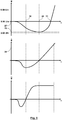
- the spatial directions are marked with a Cartesian x, y, z coordinate system, the directions x, y span a horizontal plane while the direction z indicates a vertical direction. Furthermore, in these figures, g indicates the gravitational acceleration.
- the angular positions of the product with respect to the axis of rotation of the laboratory centrifuge are explained with reference to a clock dial.
- the 12:00 o'clock position correlates with the z coordinate, where the small hand of the clock is opposite to the effect of the gravitational acceleration g, while the clock's small hand aligns with the 6 o'clock Clock position corresponds to the direction of gravity acceleration and the alignment of the small hand of the clock in the 3 o'clock position corresponds to the x-direction.
- centrifugal force or “centrifugal acceleration”.
- centrifugal acceleration or “centrifugal acceleration”. The Applicant hereby realizes that strictly speaking they do not exist and that the centrifugal force and centrifugal acceleration arise exclusively in response to a centripetal acceleration (see also d 'Alembert's mechanical approach).
- the laboratory centrifuge 1 shown here only partially has a rotor 2 which rotates about a horizontal axis of rotation 3 oriented in the y-direction.
- the rotor 2 is disc-shaped in a rough approximation, without this necessarily being the case.
- the rotor 2 forms a holder 4 or receptacle 5, by means of which or in which a product 6 is detachably held on the rotor 2.
- the holder 4 or receptacle 5 is formed with a through-hole 7 of the rotor 2, which extends in the y-direction through the rotor 2 and is formed here with an edge-closed cross-section.
- the passage recess 7 forms here on the in Fig.
- the through-hole 7 forms on the in Fig. 1 side facing away from a removal opening 9, via which the product 6 can be removed from the holder 4 or 5 recording.
- the rotor 2 has a compensation device 10, which serves to reduce or eliminate an imbalance of the rotor 2.
- the compensation device 10 has a compensation mass 11 whose distance from the axis of rotation 3 to compensate for any imbalance is variable.
- the compensation device 10 has a scale 12 along which a label 13, here an arrow 14, the balancing mass 11 moves with the change in the distance of the balancing mass 11 of the rotation axis 3. By means of the scale 12, predetermined positions of the balancing mass 11 can be selectively selected during the adjustment of the compensation device 10, which correlate, for example, respectively with different products 6, in particular different masses of the products 6.
- the rotor 2 is mounted rotatably relative to a support 15, which is formed for the illustrated embodiment with three radially extending to the axis of rotation 3 support arms 16a, 16b, 16c, which in the radially outer end portions of a base, frame or housing (not here represented) of the laboratory centrifuge 1 support.
- the drive of the rotor 2 via a drive unit 17.
- the drive shaft of the drive unit 17 is arranged coaxially to the axis of rotation 3.
- a method of operating a laboratory centrifuge according to Fig. 1 to 3 is based on Fig. 4 with reference to the time courses of the angle, the angular velocity and the angular acceleration according to Fig. 5 explains:
- the product 6 is provided. This provision of the product 6 takes place in a half space 19, which is located in front of the rotor 2 and is separated by the plane of rotation of the rotor 2 from a half space 20 located behind the rotor 2.
- the product 6 is not introduced directly into the holder 4 or receptacle 5 of the rotor 2, but using a receiving body 21, which may also be a sample carrier, in a method step 22, at least one product 6 is introduced into one Thereafter, in a method step 23, the rotor is brought into an angular position, which forms a loading position.
- This loading order is, for example, the in Fig. 1 assumed position, which is a 6:00 o'clock position.
- the at least one product 6, preferably with the receiving body 21 is introduced through the feed opening 8 into the receptacle 5 via a suitable actuator or a handling device in a method step 24.
- a subsequent method step 25 the product 6 is fastened to the holder 4 of the rotor 2 formed by the receptacle 5.
- the coupling of one takes place in this method step Coupling portion of the receiving body 21 with a corresponding, formed by the holder 4 counter-coupling region of the rotor 2.
- a process step 26 then the rotor 2 of the drive unit 17 from the 6 o'clock position according to Fig. 1 , which here forms the feed or loading position 27, slowly transferred to a time 28 in a rest angle position 29.
- the rotor 2 is first accelerated up to a time 30 counterclockwise and subsequently braked so that it has at time 28 in the rest angle position 29 an angular velocity zero. It is possible that the rotor 2 remains in the rest angle position 29 for a period of time. Preferably, however, the angular velocity reverses immediately in the rest angle position 29.
- the rest angle position 29 is an angular position in the range between a 3: 00 o'clock position and 6: 00 o'clock position, wherein with a reduced exit or Ausfpdfne Trent the sample or substance, a higher viscosity of the Substance and a greater capillary action, a greater approximation of the rest angle position 29 can be made to the 3:00 o'clock position.
- the rotor 2 with product 6 held thereon is accelerated by the rest angle position 29 with the direction of rotation reversed, that is to say in the clockwise direction.
- the product 6 at a time 33, the 6:00 o'clock position whereby for the illustrated embodiment, a passing of the feed or loading position 27 takes place.
- the rotor 2 Due to the acceleration from the rest angle position 29, the rotor 2 has with the Product 6 when passing the 6 o'clock position already an angular velocity 34, which is greater than zero.
- "momentum can be fetched" with the provision of an energy level of the rotor 2 and the product 6 in FIG. 6: 00 o'clock position, which is greater than with an immediate start from the 6 o'clock position.
- the product 6 With further acceleration in a clockwise direction, the product 6 passes through the 9:00 o'clock position with increasing angular velocity in the 12:00 o'clock position, whereby depending on the drive power of the drive unit 17, the accelerating torque can be further increased in the following or this constant at a maximum moment remains with the resulting constant angular acceleration (cf. Fig. 5 ).
- the actual centrifuging takes place at the predetermined angular velocity or a predetermined angular velocity profile. If the centrifuging is completed, the rotor 2 decelerates.
- the control of the drive unit 17 takes place in such a way that in the reversed angular position there is an exactly predetermined angular velocity and thus a centrifugal acceleration which is greater than the gravitational acceleration.
- the braking of the rotor 2 with product 6 held thereon takes place in method step 37 at an angular speed of zero until a rest angle position is reached, which is set between the 3 o'clock position and the 9 o'clock position. Position is, preferably between the 6:00 o'clock position and the 9:00 o'clock position.
- the braking takes place in an angular range of less than 270 °.
- a reverse rotation of the rotor 2 takes place with it counterclockwise in a discharge or discharge position, which is preferably at the 6 o'clock position.
- the product 6 is released from the holder 4.
- the removal of the product 6 from the rotor 2 can take place, which preferably takes place through the removal opening 9.
- Fig. 6 schematically shows during start-up approximately in a 10:00 o'clock position the product 6 with the forces acting on the product (in which case a tangential acceleration due to the acceleration of the rotor 2 during start-up is omitted for the sake of simplicity).
- Fig. 6 It can be seen that without centrifugal force due to the weight 44, the sample 42 disposed in the container 41 of the product would be accelerated radially inwardly with a component of the weight 44, ie away from the bottom of the container 41 towards the lid.
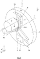
- Fig. 7 and 8th show an alternative embodiment of a laboratory centrifuge 1, in which the drive unit 17 is not arranged coaxially with the axis of rotation 3. Rather, a drive or longitudinal axis 46 of the drive unit 17 and a drive shaft thereof is arranged parallel to and spaced from the axis of rotation 3. In this case, the drive unit 17 via a geared connection 47, for example.
- a traction drive 48, coupled to the rotor 2, wherein the geared connection 47 also ensures the offset of the drive or longitudinal axis 46 relative to the rotation axis 3, wherein additionally by means of the gear Connection 47 can be a translation or translation.
- the drive unit 17 is arranged with respect to the rotation axis 3 diametrically opposite to the receptacle 5 of the rotor 2 in the 6:00 o'clock position.
- the drive unit 17 is arranged in the upper half-plane of the rotor (9:00 o'clock position to 3:00 o'clock position), while in the feed or loading position 27 and / or the unloading position the receptacle 5 in the lower half-plane (3:00 o'clock position to 9:00 o'clock position) can be arranged, whereby the drive unit 17 does not hinder the supply and removal of the product 6 from the rotor 2 and result in improved space conditions.
- the support frame 15 as shown in the area of the receptacle 5 and before and behind this in the loading position 27 and / or unloading a gap or recess through which the receptacle 5 is accessible.
- Fig. 9 shows highly schematically a sensor 49, which detects an angular position of the rotor 2, and a sensor 50, which detects the angular velocity of the rotor 2.
- the measurement signals of the sensors 49, 50 are supplied to a control unit 51, which controls the drive unit 17 for carrying out the method explained above on this basis.
- the control unit 51 can communicate with further control units, for example also for the control of handling devices and loading and unloading devices for loading and unloading the product 6. It is also possible that only a rotation angle is detected by a sensor 49 and from this an angular velocity signal is derived.
- the drive unit 17 is already controlled in terms of angle of rotation, so that only the control unit 51 controls a predetermined rotation angle, and / or that an angle signal of the drive unit 17 is processed by the control unit 48.
- the sensor 49 for detecting the angular position of the rotor 2 (or correspondingly also a sensor 50 for detecting the angular velocity of the rotor 2) may also be formed as directly integrated into the drive unit 17 sensor, which, for example, anyway for the operation of the drive unit 17 is provided in this.
- the products 6 are, for example, blood tubes which may have typical dimensions of 13 ⁇ 75 mm, 13 ⁇ 100 mm or 16 ⁇ 100 mm.
- the acceleration takes place in such a way that with the achievement of a horizontal orientation of the product (9:00 o'clock position), a centrifugal acceleration greater than 2 ⁇ g has already been achieved.
- the braking in which case preferably in the reverse angular position, ie the 12:00 o'clock position, a centrifugal acceleration of at least 2 xg acts, which then over an angular range of 180 ° to 6:00 o'clock position is braked to the angular velocity zero.
- the gravitational field for the separation by centrifugation acts specifically in Direction of the bottom of the container 41.
- the removal of the container 41 horizontal course of the separation limits the risk of mixing during removal from the laboratory centrifuge 1 is at least reduced. Such a result would otherwise be achieved only by swinging bucket rotors, while the separation limit in fixed angle rotors is typically at an angle which is not perpendicular to the normal of the vessel bottom.
- the receiving body 21 is formed as a vessel holder, which may be fixedly mounted with the rotor 2 or may be interchangeable.
- An interchangeable vessel holder is intended for use as part of a linear or plate-shaped transport system, through which the vessel can be transported to further process steps.
- the drive unit 17 and the support frame 15 are mounted in a housing, not shown, which ensures safety. By damping elements between the drive 17, support frame 15 and / or housing, the transmission of vibrations to the housing is greatly reduced.
- Fig. 10 and 11 show a further embodiment of a rotor 2 with balancing device 10.
- the balancing mass 11 is in an edge-closed through hole 52nd arranged, which has a rectangular cross section here.
- the radially oriented boundaries of the passage recess 52 form two radially oriented parallel guides 53, in particular ribs 54, between which the balancing mass 11 is guided to change their distance from the axis of rotation 3.
- the leveling compound 11 may be formed in two or more parts.
- the balancing mass 11 has a radial axis of rotation 3 oriented through threaded hole 55 through which an actuating rod 56 extends.
- the actuating rod 56 has in the with the balancing mass 11 and the threaded bore 55 interacting axial region via an external thread not shown here.
- the actuating rod 56 is rotatable in its two end regions, but mounted axially fixed relative to the rotor 2.
- the actuating rod 56 projects with the radially outer end region out of the lateral surface of the rotor 2 with an actuating or engagement surface 57.
- a screwdriver a hexagon u.
- the actuating rod 56 are rotated, which in the manner of a spindle drive, the balancing mass is moved so that the distance of the balancing mass 11 of the rotation axis 3 changes, bringing the compensation a possible imbalance can take place.
- the receiving body 21 is formed like a block or cuboid.
- the receiving body 21 has a receptacle 58 into which the product 6 can be inserted from above.
- the receptacle 58 is a blind hole 59 introduced from above against the z-direction into the receiving body 21, into which a product 6 having a cylindrical lateral surface, for example a container or test tube, can be used, wherein preferably the product 6 is secured frictionally or exclusively by the gravitational acceleration and any acting centrifugal forces in the receptacle 58.
- the receiving body 21 has a coupling region 60, via which the receiving body 21 can be coupled to the rotor 2.
- the coupling region 60 has two partial coupling regions 61, 62:
- the partial coupling region 61 is here formed with two y-oriented grooves 63, which are arranged on opposite sides of the receiving body 21.
- the grooves 63 have a trapezoidal, outward expanding cross-section.
- the rotor 2 forms in the region of the through-passage 7 on opposite sides guides 64, in this case ribs 65, whose shape and position coincide with the shape and position of the grooves 63.
- the partial coupling region 62 serves. This is formed with a groove 66, which is on the underside of the receiving body 21 with extension in the x-direction, ie transverse to the axis of rotation 3. As in Fig. 14 can be seen, the wall of the rotor 2, which defines the through-hole 7 radially outward, via a recess 67 in which a pivot lever 68 is pivotally mounted about a pivot axis 69 which is oriented parallel y-axis.
- One end region of the pivoting lever 68 carries a locking element 70, while the other end region of the pivoting lever 68 is acted upon by a spring 71 such that, without rotation of the rotor 2, the pivoting lever 68 assumes a pivoting position in which the locking element 70 is displaced radially outwards in this way, that this does not interact with the receiving body 21.
- the receiving body 21 is arranged centrally in the through-hole 7, that is to say in accordance with the predetermined axial position, the groove 63 and the locking element 70 are in a common plane with the pivoting lever 68, which is oriented transversely to the axis of rotation 3.
- the rotor 2 On the side facing away from the locking element 70 side of the pivot lever 68 carries a mass 72. If in the predetermined axial position of the receiving body 21, the rotor 2 is set in rotation, acts on the mass 72, a centrifugal force, which leads to the spring 71 causes the locking element 70 enters the groove 63, whereby a positive locking with elimination of said axial degree of freedom is formed in the y direction. In this case, the pressing of the locking element 70 is increased in the groove 63 with increasing angular velocity of the rotor 2.
- the receiving body 21 has only one receptacle 58. It is understood that a plurality of receptacles 58 for several products 6 may be provided on a single receiving body 21.
- Both the balancing mass 11 and the receiving body 21 are secured against rotation about the rotation axis 3 with large contact surfaces. It is advantageous if the rotor 2 has flat end faces, from which in particular the receiving body 21 and the compensation mass 11 do not protrude parallel to the axis of rotation 3, since otherwise an increased air resistance would arise with increasing the power requirement for generating the rotational movement of the rotor. 2 It is possible that the leadership of the balancing mass 11 and / or the receiving body 21 takes place on the rotor 2 in the manner of a "dovetail guide". It is also possible that the recesses 7, 52, for example, by a centrifugally operated self-closing or manually closed cover plate, are closed during centrifugation to the outside.
- an additional rotor in particular a rotor disc can be accelerated simultaneously with the acceleration of the rotor 2 in an opposite direction of rotation to compensate for the overturning moment. This can lead to a spin compensation or compensation of the overturning moment independently of the acting acceleration. If the additional rotor has the same mass moment of inertia as the rotor 2, the additional rotor can be driven at the same angular velocity and acceleration. If an additional rotor is used with a different mass moment of inertia, a corresponding over or under reduction of the rotary movement must take place.
- a laboratory centrifuge 1 is on a preferably horizontal surface
- an assembly of the laboratory centrifuge 1 on a laboratory wall or on another vertical support wall of a furnishing article, wearer u. ⁇ . Whereby the rotation plane of the rotor 2 can be aligned parallel to the wall, whereby a particularly flat and space-saving design is possible.
- the rotor 2 is formed in a lightweight construction.
- this has advantages with regard to the aforementioned tilting moment, which becomes smaller with reduced mass or reduced mass moment of inertia.
- the required high accelerations with comparatively small drive torques of the drive unit 17 can be brought about.
- lightweight construction for example, light aluminum alloys, carbon fiber reinforced plastics, a combined plastic / metal construction can be used.
- weight-reducing material recesses continuous or non-continuous recesses, for example in the radial direction and / or parallel to the axis of rotation).
- a fixation of the rotor 2 in the loading and / or unloading position is desirable.
- a fixing holding torque can be applied to the rotor 2 by the drive unit 17, so that no additional fixing devices are required. It is also entirely possible, however, that a fixing of the rotor 2, the drive unit 17 and / or the geared connection 47 via a latching or locking device which manually and / or automatically via an actuator, which may be controlled by the control unit 51, operated and / or can be solved.
Description
Die Erfindung betrifft eine Laborzentrifuge sowie ein Verfahren zum Betrieb derselben. Derartige Laborzentrifugen finden Einsatz bspw. in der Biotechnologie, der pharmazeutischen Industrie, der Medizin und der Umweltanalytik. Mittels einer Laborzentrifuge erfolgt ein Zentrifugieren eines Produkts, insbesondere eines Behälters oder Gefäßes mit darin angeordneter Probe oder Substanz, mit Drehzahlen, welche mehr als 3.000 Umdrehungen/min, bspw. 15.000 Umdrehungen/min oder mehr betragen können, wobei hiermit bspw. auf das Produkt wirkende Beschleunigungen erzeugt werden, welche mehr als 15.000 x g, bspw. mehr als 16.000 x g, mehr als 20.000 x g bis hin zu mehr als 60.000 x g betragen können. Durch die Zentrifugation soll ein von der Probe oder der Substanz gebildetes Stoffgemisch in Komponenten unterschiedlicher Dichte zerlegt werden. Je nach den chemischen und/oder physikalischen Eigenschaften des Stoffgemisches kann während der Zentrifugation ergänzend eine gezielte Steuerung der Druck- und/oder Temperaturverhältnisse erfolgen. Um lediglich einige Beispiele zu nennen, kann der Einsatz einer Laborzentrifuge im Zusammenhang mit
- einer Polymerase-Kettenreaktion (PCR),
- einer Bestimmung des Hämatokrits,
- zytologischen Untersuchungen oder
- dem Zentrifugieren von Mikrotitern, Blutbeuteln, Erdölgefäßen oder Blutgefäßen u. ä erfolgen.
- a polymerase chain reaction (PCR),
- a determination of the hematocrit,
- cytological examinations or
- the centrifuging of microtitres, blood bags, petroleum vessels or blood vessels u. take place.
Grundsätzlich finden in Laborzentrifugen Rotoren Einsatz, welche als Winkelrotoren oder Ausschwingrotoren ausgebildet sind und um eine vertikale Rotationsachse rotieren.Basically rotors are used in laboratory centrifuges, which are designed as angular rotors or swing-bucket rotors and rotate about a vertical axis of rotation.
Die Druckschrift
Weiterer Stand der Technik ist aus
Der vorliegenden Erfindung liegt die Aufgabe zugrunde,
- ein Verfahren zum Betrieb einer Laborzentrifuge, bei welcher der Rotor um eine horizontale Rotationsachse rotiert, sowie
- eine Laborzentrifuge
- a method for operating a laboratory centrifuge, wherein the rotor rotates about a horizontal axis of rotation, and
- a laboratory centrifuge
Die Aufgabe der Erfindung wird erfindungsgemäß mit den Merkmalen der unabhängigen Patentansprüche gelöst. Weitere bevorzugte erfindungsgemäße Ausgestaltungen sind den abhängigen Patentansprüchen zu entnehmen.The object of the invention is achieved with the features of the independent claims. Further preferred embodiments according to the invention can be found in the dependent claims.
Die Erfindung betrifft ein Verfahren zum Betrieb einer Laborzentrifuge zum Zentrifugieren eines Produkts. Vorzugsweise handelt es sich bei dem Produkt um einen Behälter oder ein Gefäß, welcher/welches eine Probe oder eine Substanz enthält. Der Behälter oder das Gefäß kann dabei eine obere Öffnung besitzen, über welche die Probe oder Substanz eingebracht und/oder entnommen werden kann. Hierbei kann die obere Öffnung des Gefäßes oder Behälters während des Zentrifugierens offen sein oder (bspw. mit einem Stopfen oder Deckel) verschlossen sein.The invention relates to a method for operating a laboratory centrifuge for centrifuging a product. Preferably, the product is a container or vessel containing a sample or substance. The container or the vessel may have an upper opening through which the sample or substance can be introduced and / or removed. In this case, the upper opening of the vessel or container may be open during centrifuging or closed (for example with a stopper or lid).
Die im Rahmen der Erfindung eingesetzte Laborzentrifuge verfügt über einen Rotor beliebiger Bauart, welcher um eine horizontale Rotationsachse rotiert und an dem das Produkt gehalten ist, was zwecks Erzeugung der Zentrifugalkraft beabstandet von der Rotationsachse erfolgt. Das Halten des Produkts an dem Rotor kann hierbei beliebig erfolgen, wobei das Halten an dem Rotor starr oder beweglich, grundsätzlich entsprechend einem Ausschwingrotor oder vergleichbar einer "Gondel eines Riesenrads" erfolgen kann. Um lediglich ein weiteres nicht beschränkendes Beispiel zu nennen, kann das Halten des Produkts an dem Rotor derart erfolgen, dass eine Längsachse des Produkts radial zur Rotationsachse orientiert ist, wobei dann die Öffnung des Behälters oder Gefäßes der Rotationsachse zugewandt sein kann.The laboratory centrifuge used in the invention has a rotor of any type, which rotates about a horizontal axis of rotation and on which the product is held, which takes place in order to generate the centrifugal force spaced from the axis of rotation. The holding of the product on the rotor can in this case take place arbitrarily, wherein the holding on the rotor can be rigid or movable, basically according to a swing-bucket rotor or comparable to a "gondola of a Ferris wheel". To mention just another non-limiting example, the product may be held on the rotor such that a longitudinal axis of the product is oriented radially to the axis of rotation, in which case the opening of the container or vessel may face the axis of rotation.
Gemäß dem Stand der Technik wird in Kauf genommen, dass mit dem Anlaufen und Abbremsen der Laborzentrifuge das Produkt temporär vertikalen Beschleunigungen oder Beschleunigungskomponenten ausgesetzt ist, deren Richtungssinn sich je nach Winkelstellung des Produkts an dem Rotor hinsichtlich der Rotationsachse ändert. Ist bspw. ein Behälter des Produkts mit seiner Längsachse radial zur Rotationsachse orientiert mit zu der Rotationsachse weisender Öffnung des Behälters (im Folgenden auch "beispielhafte Anordnung"), so wirkt für vernachlässigbar kleine Zentrifugalkräfte am Anfang des Anlaufvorgangs sowie am Ende des Abbremsvorgangs in einer 6:00-Uhr-Stellung des Produkts die Erdbeschleunigung in Richtung des Bodens des Behälters, also von der oberen Öffnung des Behälters weg, während in der 12:00-Uhr-Stellung die Erdbeschleunigung in entgegengesetzte Richtung, also von dem Boden des Behälters weg und in Richtung der Öffnung des Behälters wirkt. Solange der Rotor mit einer Winkelgeschwindigkeit rotiert, welche eine unzureichende Zentrifugalbeschleunigung erzeugt, führt zwar diese Zentrifugalbeschleunigung dazu, dass in der 12:00-Uhr-Stellung die auf die Probe oder Substanz wirkende resultierende Beschleunigung, die sich aus der Überlagerung der Zentrifugalbeschleunigung und der Erdbeschleunigung ergibt, reduziert ist. Dennoch ändert sich für den Umlauf des Produkts um die Rotationsachse der Richtungssinn der in vertikaler Richtung auf die Probe wirkenden resultierenden Beschleunigung. Diese führt sowohl während des Anlaufens der Laborzentrifuge als auch während des Abbremsens der Laborzentrifuge unter Umständen zu einer unerwünschten Durchmischung der Probe, welche letztendlich das Ergebnis des Zentrifugierens unerwünscht beeinträchtigt. Zum anderen birgt die Umkehrung der resultierenden Beschleunigung in der oberen Halbebene das Risiko in sich, dass die Probe aus der oberen Öffnung des Behälters austritt. Somit ist unter Umständen der Einsatz der Laborzentrifuge eingeschränkt auf Produkte mit einem Behälter oder Gefäß, bei welchem die obere Öffnung verschlossen ist. Für offene Behälter oder Gefäße ist der Einsatz der Laborzentrifuge eingeschränkt auf Produkte, bei welchen eine Fließfähigkeit der Probe oder Substanz und/oder eine Kapillarwirkung derart vorgegeben sind, dass ein "Herauslaufen" der Probe oder Substanz zumindest während des Zeitraums, in welchem sich die Probe in dem Winkelbereich der oberen Halbebene befindet, nicht möglich ist.According to the prior art, it is accepted that with the start-up and deceleration of the laboratory centrifuge, the product is temporarily exposed to vertical accelerations or acceleration components whose sense of direction changes with respect to the axis of rotation, depending on the angular position of the product on the rotor. If, for example, a container of the product with its longitudinal axis is oriented radially with respect to the axis of rotation opening of the container (hereinafter also "exemplary arrangement"), so acts for negligible centrifugal forces at the beginning of the startup process and at the end of the braking process in a 6th : 00 o'clock position of the product, the acceleration of gravity in the direction of the bottom of the container, ie from the upper opening of the container, while in the 12 o'clock position, the gravitational acceleration in the opposite direction, ie away from the bottom of the container and in the direction of the opening of the container acts. As long as the rotor rotates at an angular velocity that produces insufficient centrifugal acceleration, this centrifugal acceleration causes the resulting acceleration acting on the sample or substance resulting from the superposition of centrifugal acceleration and gravitational acceleration at the 12:00 o'clock position results, is reduced. Yet For the rotation of the product about the rotation axis, the sense of direction of the resulting acceleration acting on the sample in the vertical direction changes. This may lead to an undesired mixing of the sample, both during the start-up of the laboratory centrifuge and during the deceleration of the laboratory centrifuge, which ultimately undesirably affects the result of the centrifuging. On the other hand, reversing the resulting acceleration in the upper half-plane poses the risk of the sample leaking out of the upper opening of the container. Thus, the use of the laboratory centrifuge may be limited to products having a container or vessel with the top opening closed. For open containers or vessels, the use of the laboratory centrifuge is limited to products in which a flowability of the sample or substance and / or a capillary action are predetermined such that a "run-out" of the sample or substance at least during the period in which the sample is not possible in the angular range of the upper half plane.
Für das erfindungsgemäße Verfahren finden zur Vermeidung dieser Nachteile und/oder Einschränkungen zwei Maßnahmen alternativ oder kumulativ Einsatz:
- a) Eine Ausgestaltung der Erfindung betrifft das Anlaufen der Laborzentrifuge. Erfindungsgemäß befindet sich Produkt an dem Rotor zunächst in einer Ruhe-Winkelstellung (oder wird in diese verbracht). In der Ruhe-Winkelstellung besitzt der Rotor mit dem Produkt eine Winkelgeschwindigkeit von Null. In dieser Ruhe-Winkelstellung ist das Produkt zwischen einer 3:00-Uhr-Stellung und einer 9:00-Uhr-Stellung (also in der unteren Hälfte eines imaginären Uhren-Zifferblatts) angeordnet. In der Ruhe-Winkelstellung wirkt somit in jedem Fall die Erdbeschleunigung zumindest mit einer Komponente von der Rotationsachse radial nach außen. In der "beispielhaften Anordnung" wirkt in der Ruhe-Winkelstellung zumindest eine Komponente der Erdbeschleunigung auf die Probe in Richtung des Bodens des Behälters. Ausgehend von dieser Ruhe-Winkelstellung wird dann der Rotor beschleunigt, bis das Produkt erstmalig in einer 12:00-Uhr-Stellung angeordnet ist, in welcher sich der Richtungssinn der Wirkung der Gravitation gegenüber einer 6:00-Uhr-Stellung umgekehrt hat und welche somit als Umkehr-Winkelstellung bezeichnet wird.
Um zu vermeiden, dass sich in der Umkehr-Winkelstellung der Richtungssinn der resultierenden Beschleunigung, die sich aus der Überlagerung der Erdbeschleunigung und der Zentrifugalbeschleunigung ergibt, umkehrt, wird der Rotor erfindungsgemäß gezielt derart beschleunigt, dass dieser mit dem Erreichen der Umkehr-Winkelstellung bereits eine Winkelgeschwindigkeit erreicht hat, welche so groß ist, dass die auf das Produkt wirkende Zentrifugalbeschleunigung größer ist als die Erdbeschleunigung. Auf diese Weise wirkt in der Umkehr-Winkelstellung eine resultierende Beschleunigung, welche geringfügig größer ist als Null und radial nach außen orientiert ist, was für die "beispielhafte Anordnung" bedeutet, dass auch in der Umkehr-Winkelstellung die Probe in dem Behälter zumindest geringfügig in Richtung des Bodens beschleunigt wird. Eine auf das Produkt während des Anlaufens der Laborzentrifuge wirkende resultierende Beschleunigung hat damit erfindungsgemäß keine vertikale Komponente, welche ihren Richtungssinn verändert. - b) Ebenfalls möglich ist, dass der Abbremsvorgang in die Ruhe-Winkelstellung dann aus der Umkehr-Winkelstellung eingeleitet wird, wenn die Winkelgeschwindigkeit in der Umkehr-Winkelstellung innerhalb eines vorgegebenen Winkelgeschwindigkeitsbereichs liegt (solange gewährleistet ist, dass diese in der Umkehr-Winkelstellung so groß ist, dass die auf das Produkt wirkende Zentrifugalbeschleunigung größer ist als die Erdbeschleunigung). Ebenfalls möglich ist, dass zuvor gezielt eine spezifische vorgegebene Winkelgeschwindigkeit herbeigeführt wird und dann ausgehend von dieser vorgegebenen spezifischen Winkelgeschwindigkeit mit Erreichen der Umkehr-Winkelstellung des Produkts der erläuterte Abbremsvorgang bis in die Ruhe-Winkelstellung herbeigeführt wird.
- a) An embodiment of the invention relates to the start-up of the laboratory centrifuge. According to the invention, product is first (or is placed) on the rotor in a rest angle position. In the rest angle position, the rotor has an angular velocity of zero with the product. In this rest position, the product is placed between a 3 o'clock position and a 9 o'clock position (that is, in the lower half of an imaginary clock dial). In the rest angle position, therefore, in each case the gravitational acceleration acts at least with a component of the rotation axis radially outward. In the "exemplary arrangement", at least one component of the gravitational acceleration acts on the sample in the rest angle position in the direction of the bottom of the container. Starting from this rest angle position, the rotor is then accelerated until the product is first placed in a 12:00 o'clock position where the sense of direction of gravitational action has reversed from a 6:00 o'clock position and which thus referred to as reverse angular position.
In order to avoid that in the reversal angular position of the sense of direction of the resulting acceleration, resulting from the superposition of gravitational acceleration and the centrifugal acceleration results in reverse, the rotor according to the invention is selectively accelerated so that it has already reached an angular velocity with reaching the reverse angular position, which is so great that the force acting on the product centrifugal acceleration is greater than the gravitational acceleration. In this way acts in the reverse angular position, a resulting acceleration, which is slightly greater than zero and radially outwardly oriented, which means for the "exemplary arrangement" that even in the reverse angular position, the sample in the container at least slightly in Direction of the ground is accelerated. A resulting acceleration acting on the product during the start-up of the laboratory centrifuge thus has according to the invention no vertical component which changes its sense of direction. - b) It is also possible that the deceleration operation is initiated in the rest angle position from the reverse angular position when the angular velocity in the reverse angular position is within a predetermined angular velocity range (as long as it is ensured that in the reverse angular position so large is that the centrifugal acceleration acting on the product is greater than the gravitational acceleration). It is also possible that previously specifically a specific predetermined angular velocity is brought about and then starting from this predetermined specific angular velocity with reaching the reverse angular position of the product of the explained deceleration is brought into the rest angle position.
Im Rahmen der Erfindung erfolgt die Beschleunigung während des Anlaufvorgangs und/oder das Abbremsen von einer Winkelgeschwindigkeit, in welcher die Zentrifugalbeschleunigung größer ist als die Erdbeschleunigung, auf eine Winkelgeschwindigkeit von Null (bzw. umgekehrt) über einen Winkelbereich, welcher kleiner als 270° ist.In the context of the invention, the acceleration during the startup process and / or the deceleration from an angular velocity in which the centrifugal acceleration is greater than the gravitational acceleration, to an angular velocity of zero (or vice versa) over an angular range which is less than 270 °.
Für die Erzeugung der erforderlichen Beschleunigung oder Abbremsung gibt es vielfältige Möglichkeiten. Um ein nicht beschränkendes Beispiel zu nennen, können der Antrieb und die Steuerung desselben so ausgebildet sein, dass die erforderlichen beschleunigenden oder abbremsenden Momente in dem angegebenen Winkelbereich erzeugt werden können. Gemäß einem weiteren nicht beschränkenden Beispiel kann die Beschleunigung oder Abbremsung durch die gezielte Ankopplung oder Abkopplung einer trägen Masse herbeigeführt oder unterstützt werden. So kann für den Beschleunigungsvorgang zunächst (u. U. auch in einem länger andauernden Beschleunigungsvorgang) eine träge Masse mit einer kinetischen Rotationsenergie versehen werden, welche mindestens so groß ist wie die kinetische Energie, wenn der Rotor und die träge Masse gemeinsam mit einer Winkelgeschwindigkeit rotieren, für die die Zentrifugalbeschleunigung größer ist als die Erdbeschleunigung, während sich zunächst während dieser Beschleunigung der trägen Masse der Rotor mit dem Produkt in der Ruhe-Winkelstellung befindet. Mit dem Erreichen der erforderlichen kinetischen Energie erfolgt dann die Kupplung der trägen Masse mit dem Rotor, womit die träge Masse den Rotor "mitnimmt". Hierbei kann eine Kupplung plötzlich oder sukzessive geschlossen werden, eine gesteuert schließende Kupplung eingesetzt werden oder eine Rutschkupplung eingesetzt werden. Die vollständige Kopplung der Drehbewegung der trägen Masse mit der Drehbewegung des Rotors erfolgt bis zum Erreichen der Umkehr-Winkelstellung, womit dann das Produkt mit dem Rotor die erforderliche Winkelgeschwindigkeit erreicht hat.There are many possibilities for generating the required acceleration or deceleration. By way of non-limiting example, the drive and control thereof may be configured to provide the required accelerating or decelerating moments within the indicated angular range. According to a further non-limiting example, the acceleration or deceleration may be induced or assisted by the intentional coupling or decoupling of an inertial mass become. Thus, for the acceleration process, initially (possibly also in a prolonged acceleration process) an inertial mass can be provided with a kinetic rotational energy which is at least as great as the kinetic energy when the rotor and the inertial mass rotate together at an angular velocity for which the centrifugal acceleration is greater than the gravitational acceleration, while initially during this acceleration of the inertial mass of the rotor with the product is in the rest angle position. When the required kinetic energy is reached, the inertial mass is then coupled to the rotor, whereby the inertial mass "takes along" the rotor. Here, a clutch can be closed suddenly or successively, a controlled closing clutch can be used or a slip clutch can be used. The complete coupling of the rotational movement of the inertial mass with the rotational movement of the rotor takes place until reaching the reverse angular position, which then the product has reached the required angular velocity with the rotor.
Mit der Vorgabe, dass der Rotor in der Umkehr-Winkelstellung eine Winkelgeschwindigkeit besitzen soll, welche so groß ist, dass die auf das Produkt wirkende Zentrifugalbeschleunigung größer ist als die Erdbeschleunigung, ist lediglich eine Untergrenze angegeben. Vorzugsweise ist die Winkelgeschwindigkeit in der Umkehr-Winkelstellung so groß, dass die auf das Produkt wirkende Zentrifugalbeschleunigung zumindest dem Zweifachen der Erdbeschleunigung entspricht.With the proviso that the rotor in the reverse angular position should have an angular velocity which is so great that the centrifugal acceleration acting on the product is greater than the gravitational acceleration, only a lower limit is specified. Preferably, the angular velocity in the reverse angular position is so great that the centrifugal acceleration acting on the product is at least twice the gravitational acceleration.
Grundsätzlich möglich ist, dass die Ruhe-Winkelstellung des Produkts einer 6:00-Uhr-Winkelstellung entspricht, so dass die Herbeiführung der Winkelgeschwindigkeit in der Umkehr-Winkelstellung in einem Winkelbereich von 180° erforderlich ist. Erfindungsgemäß weicht aber die Ruhe-Winkelstellung von einer 6:00-Uhr-Winkelstellung ab (wobei aber weiterhin gilt, dass das Produkt in der Ruhe-Winkelstellung zwischen einer 3:00-Uhr-Stellung einer 9:00-Uhr-Stellung angeordnet ist). Liegt bspw. in einer Extremüberlegung die Ruhe-Winkelstellung in einer 3:00-Uhr-Stellung (womit ein nicht fließfähiges Medium, welches die Probe bildet, gerade noch nicht in Richtung der Rotationsachse beschleunigt wird), durchläuft die Probe auf dem Weg zur Umkehr-Winkelstellung einen Winkelbereich von 270°, wobei nach Beschleunigung über einen Winkel von 90° und mit dem Erreichen der 6:00-Uhr-Stellung das Produkt bereits auf eine von Null verschiedene Winkelgeschwindigkeit beschleunigt worden ist. Insgesamt kann durch diese Maßnahme der Winkelbereich, über welchen die Beschleunigung des Rotors und des Produkts erfolgen muss, um die erforderliche Winkelgeschwindigkeit in der Umkehr-Winkelstellung zu erreichen, vergrößert werden. Mit dieser Vergrößerung des Winkelbereichs kann einerseits eine Reduzierung der erforderlichen Beschleunigungs- und Abbremskräfte herbeigeführt werden, womit die Anforderungen an den Antrieb und die Steuerung desselben reduziert werden können. Andererseits führt die unter Umständen starke Beschleunigung oder Abbremsung zwischen der Ruhe-Winkelstellung und der Umkehr-Winkelstellung zu einer auf das Produkt wirkenden unerwünschten Tangentialbeschleunigung, welche durch Vergrößerung des Winkelbereichs, über welchen die Abbremsung oder Beschleunigung erfolgen muss, reduziert werden kann.In principle, it is possible for the product to rest at an angle of 6:00 o'clock, so that the angular velocity in the reverse angular position is required in an angular range of 180 °. However, according to the invention, the rest angle position deviates from a 6:00 o'clock angular position (but still applies that the product is arranged in the rest angle position between a 3:00 o'clock position of a 9:00 o'clock position ). For example, in an extreme consideration, if the resting angular position is at a 3:00 o'clock position (thus, a non-fluid medium forming the sample is just not being accelerated in the direction of the axis of rotation), the sample travels on the way to the reversal Angular position an angular range of 270 °, after accelerating over an angle of 90 ° and when reaching the 6:00 o'clock position, the product has already been accelerated to a non-zero angular velocity. Overall, by this measure, the angular range over which the acceleration of the rotor and the product must take place by the required angular velocity in the reverse angular position to be increased. With this increase in the angular range, on the one hand, a reduction of the required acceleration and deceleration forces can be brought about, with which the requirements for the drive and the control of the same can be reduced. On the other hand, the possibly strong acceleration or deceleration between the rest angle position and the reverse angle position leads to an undesired tangential acceleration acting on the product, which can be reduced by increasing the angular range over which the deceleration or acceleration must take place.
Erfindungsgemäß erfolgt das Be- und Entladen des Produkts zu und von dem Rotor in einer Be- und Entladestellung, welche der 6:00-Uhr-Stellung entspricht. Hieran anschließend wird dann zunächst mittels des Antriebs der Rotor mit einem ersten Drehrichtungssinn in die Ruhe-Winkelstellung überführt, von welcher dann die Beschleunigung mit einem entgegengesetzten zweiten Drehrichtungssinn in Richtung der Umkehr-Winkelstellung erfolgt. Das Entsprechende gilt auch für den Abbremsvorgang, für welchen bis zur Ruhe-Winkelstellung während des Abbremsens eine Verdrehung des Rotors mit einem ersten Drehrichtungssinn erfolgt mit anschließendem Zurückdrehen mit einem entgegengesetzten zweiten Drehrichtungssinn von der Ruhe-Winkelstellung in die Entladestellung. Anders gesagt kann mit der erfindungsgemäßen Maßnahme bei dem Beschleunigen oder Abbremsen "Anlauf" genommen werden bzw. beim Abbremsen eine Art "Überschwingen" der Probe über die 6:00-Uhr-Winkelstellung erfolgen.According to the loading and unloading of the product takes place to and from the rotor in a loading and unloading position, which corresponds to the 6:00 o'clock position. Following this, the rotor is then first transferred by means of the drive with a first direction of rotation in the rest-angular position, from which then the acceleration takes place with an opposite second direction of rotation in the direction of the reverse angular position. The same applies to the braking process, for which up to the rest angle position during braking, a rotation of the rotor with a first direction of rotation takes place with subsequent turning back with an opposite second direction of rotation of the rest angle position in the unloading. In other words, can be taken with the inventive measure in the acceleration or deceleration "start" or done during braking a kind of "overshoot" of the sample on the 6: 00-clock angular position.
Möglich ist, dass das Produkt manuell dem Rotor zugeführt wird, mit dem Rotor gekoppelt wird, von dem Rotor entkoppelt wird und/oder von dem Rotor entfernt wird. In bevorzugter Ausgestaltung der Erfindung wird allerdings das Produkt automatisch dem Rotor zugeführt und/oder automatisch von dem Rotor entfernt, wobei durchaus auch möglich ist, dass zusätzlich eine automatische Kopplung und/oder Entkopplung des Produkts mit und von dem Rotor erfolgt. Es hat sich gezeigt, dass die derartige Automatisierung der Handhabung des Produkts besonders gut möglich ist bei einer hier einschlägigen Laborzentrifuge mit einem Rotor, der um eine horizontale Rotationsachse rotiert, was insbesondere dadurch begründet ist, dass eine automatisierte Handhabung des Produkts in einer horizontalen Handhabungsebene besonders einfach ist und die automatisierte Annäherung der Probe an den Rotor und die Entfernung von diesem für einen Rotor mit horizontaler Rotationsachse gewährleistet werden kann.It is possible that the product is fed manually to the rotor, is coupled to the rotor, is decoupled from the rotor and / or removed from the rotor. In a preferred embodiment of the invention, however, the product is automatically fed to the rotor and / or automatically removed from the rotor, which is quite possible that in addition an automatic coupling and / or decoupling of the product takes place with and from the rotor. It has been found that such automation of the handling of the product is particularly well possible in a relevant laboratory centrifuge with a rotor which rotates about a horizontal axis of rotation, which is in particular due to the fact that an automated handling of the product in a horizontal handling level particularly is simple and the automated approach of the sample to the rotor and the distance of this can be ensured for a rotor with a horizontal axis of rotation.
Durchaus möglich ist, dass die (automatische oder manuelle) Zuführung des Produkts zu dem Rotor und das Entfernen des Produkts von dem Rotor nach dem Zentrifugieren mit unterschiedlichem Richtungssinn, also die Zuführung mit einer Hinbewegung sowie das Entfernen mit einer Rückbewegung, erfolgt. Erfindungsgemäß wird für eine bevorzugte Weiterbildung allerdings vorgeschlagen, dass das automatische Zuführen des Produkts zu dem Rotor und das Entfernen des Produkts von dem Rotor nach dem Zentrifugieren mit demselben Richtungssinn erfolgt. Auf diese Weise ist ermöglicht, dass die Handhabung der Produkte vor dem Zentrifugieren und die Zuführung der Produkte auf einer Seite des Rotors erfolgt, während die Entfernung und weitere Handhabung der zentrifugierten Produkte auf der anderen Seite des Rotors erfolgt. Für die Rotation des Rotors um eine horizontale Achse bedeutet dies, dass die Rotationsebene des Rotors einen Halbraum, in welchem das Vorbereiten und Zuführen der Produkte erfolgt, trennt von einem Halbraum, in welchem das Entfernen des Produkts (u. U. mit weiterer Verarbeitung) erfolgen kann. Vorzugsweise erfolgt hierbei die Bewegung des Produkts beim Zuführen und Entfernen parallel zu der Rotationsachse des Rotors, wobei das Produkt für das Zuführen in eine Durchgangsausnehmung des Rotors eingebracht wird und für das Entfernen auf der anderen Seite aus der Durchgangsausnehmung des Rotors entnommen werden kann. Möglich ist bspw., dass die Ausnehmung als im Querschnitt randgeschlossene Ausnehmung eines insbesondere scheibenartigen Rotors ausgebildet ist. Durchaus möglich ist aber auch, dass die Ausnehmung randseitig an dem bspw. scheibenartigen Rotor gebildet ist, womit die Ausnehmung auch im Querschnitt randoffen ausgebildet sein kann.It is quite possible that the (automatic or manual) feeding of the product to the rotor and the removal of the product from the rotor after centrifuging with different sense of direction, ie the supply with a forward movement and the removal with a return movement occurs. According to the invention, however, it is proposed for a preferred development that the automatic feeding of the product to the rotor and the removal of the product from the rotor after centrifuging take place with the same sense of direction. In this way, the handling of the products prior to centrifuging and the delivery of the products on one side of the rotor is made possible while the removal and further handling of the centrifuged products takes place on the other side of the rotor. For the rotation of the rotor about a horizontal axis, this means that the plane of rotation of the rotor separates a half space in which the preparation and feeding of the products takes place, from a half space in which the removal of the product (possibly with further processing) can be done. Preferably, in this case, the movement of the product during feeding and removal takes place parallel to the axis of rotation of the rotor, wherein the product for feeding into a through-hole of the rotor is introduced and can be removed for removal on the other side of the through-hole of the rotor. It is possible, for example., That the recess is formed as a cross-sectionally edge-closed recess of a particular disc-like rotor. Quite possible, however, is that the recess is formed on the edge side of the example. Disk-like rotor, whereby the recess can be formed open-edge in cross section.
In weiterer Ausgestaltung des erfindungsgemäßen Verfahrens wird über eine Ausgleichseinrichtung eine von der Masse des Produkts abhängige Unwucht des Rotors reduziert. Die Ausgleichseinrichtung kann dabei automatisch oder manuell betrieben werden. Beispielsweise kann die Ausgleichseinrichtung mit einer Zusatzmasse gebildet sein, welche diametral gegenüberliegend zu dem Produkt an dem Rotor gehalten ist und deren Abstand je nach Masse des Produkts verändert werden kann. Hierbei kann eine Verstellung des Abstands einer Ausgleichsmasse von der Rotationsachse stufenlos oder in Stufen erfolgen mittels eines Aktuators oder einer manuellen Verstelleinrichtung. Möglich ist auch, dass eine Ausgleichsmasse mit einer Skala zusammenwirkt, so dass bei einem bekannten Typ eines Produkts gezielt eine durch die Skala vorgegebene Stellung der Ausgleichsmasse herbeigeführt werden kann.In a further refinement of the method according to the invention, an imbalance of the rotor, which is dependent on the mass of the product, is reduced via a compensating device. The compensation device can be operated automatically or manually. For example, the compensation device may be formed with an additional mass, which is held diametrically opposite to the product on the rotor and whose distance can be changed depending on the mass of the product. Here, an adjustment of the distance of a balancing mass from the axis of rotation continuously or in stages by means of an actuator or a manual adjustment. It is also possible that a balancing mass cooperates with a scale, so that in a known type of product targeted by the scale predetermined position of the balancing mass can be brought about.
In weiterer Ausgestaltung der Erfindung ist das Produkt über eine Halterung an dem Rotor fixiert. Durchaus möglich ist hierbei, dass das Produkt unmittelbar an der Halterung des Rotors fixiert ist. Ein Fixieren kann auf beliebige Weise erfolgen, insbesondere mit einem Einklemmen des Produkts oder einem Halten des Produkts über eine Halte-, Rast- oder Verriegelungseinrichtung. Möglich ist auch, dass die Fixierung fliehkraftbetätigt durch die Rotation des Rotors betätigt wird. Im Extremfall ist sogar möglich, dass die Halterung ausschließlich über eine Aufnahme für das Produkt verfügt, in welche das Produkt radial nach außen eingelegt wird und an deren Absatz oder Boden sich das Produkt radial nach außen abstützt. In diesem Fall ist in der Ruhestellung sowie während des Anlaufens des Rotors das Produkt durch die Gravitationskraft und die sich aufbauende Zentrifugalkraft gegen den Boden oder Absatz der Aufnahme gepresst. Mit zunehmender Winkelgeschwindigkeit des Rotors wird die Anpressung des Produkts an den Boden oder den Absatz der Aufnahme gestärkt. Es versteht sich, dass zusätzlich zwischen Aufnahme und Produkt ein sichernde Reibkraft, eine Rast- oder Verriegelungseinrichtung oder eine beliebige andere Sicherungseinrichtung wirken kann.In a further embodiment of the invention, the product is fixed via a holder on the rotor. Quite possible here is that the product is fixed directly to the holder of the rotor. A fixing can be done in any way, in particular with a pinching of the product or holding the product via a holding, latching or locking device. It is also possible that the fixation centrifugally operated by the rotation of the rotor is actuated. In extreme cases, it is even possible that the holder has only a receptacle for the product, in which the product is inserted radially outward and at the shoulder or bottom, the product is supported radially outward. In this case, in the rest position and during the start-up of the rotor, the product is pressed by the gravitational force and the building up centrifugal force against the bottom or shoulder of the receptacle. With increasing angular velocity of the rotor, the pressure of the product is strengthened to the bottom or the heel of the recording. It is understood that in addition between recording and product a locking friction force, a locking or locking device or any other safety device can act.
In weiterer Ausgestaltung der Erfindung ist die Halterung mit einem Aufnahmekörper gebildet. Der Aufnahmekörper bildet einerseits eine Aufnahme aus, in welcher das Produkt angeordnet wird und/oder an welcher das Produkt gehalten werden kann. Andererseits bildet der Aufnahmekörper einen Kopplungsbereich aus. Über den Kopplungsbereich kann der Aufnahmekörper mit dem in der Aufnahme angeordneten Produkt an dem Rotor befestigt werden. So kann eine gezielte Gestaltung einerseits der Aufnahme für die Wechselwirkung mit dem Produkt und andererseits des Kopplungsbereichs für die Wechselwirkung mit dem Rotor erfolgen. Möglich ist hierbei, dass das Produkt der Aufnahme des Aufnahmekörpers zugeführt wird, wenn der Aufnahmekörper bereits an dem Rotor befestigt ist. Vorzugsweise erfolgt aber das Einbringen des Produkts in die Aufnahme des Aufnahmekörpers, bevor das Produkt dann mit dem Aufnahmekörper dem Rotor zugeführt wird und die Kopplung des Aufnahmekörpers im Kopplungsbereich mit dem Rotor erfolgt. Der Einsatz eines Aufnahmekörpers kann bspw. auch dann von Vorteil sein, wenn gewünscht ist, dass unterschiedliche Produkte mit unterschiedlichen Geometrien mit demselben Rotor zentrifugiert werden. In diesem Fall können Aufnahmekörper verwendet werden, welche dieselben Kopplungsbereiche besitzen, aber unterschiedliche Aufnahmen für die unterschiedlichen Produkte mit unterschiedlichen Geometrien besitzen. Denkbar ist auch, dass die Aufnahme mittels eines Adapters gebildet ist, welcher die Aufnahme spezifisch an die jeweilige Geometrie des Produkts anpasst. Möglich ist auch, dass der Aufnahmekörper über eine fliehkräftbetätigte Rast- oder Verriegelungseinrichtung an dem Rotor fixiert wird.In a further embodiment of the invention, the holder is formed with a receiving body. On the one hand, the receiving body forms a receptacle in which the product is arranged and / or on which the product can be held. On the other hand, the receiving body forms a coupling region. The receiving body can be fastened to the rotor with the product arranged in the receptacle via the coupling region. Thus, a targeted design on the one hand, the inclusion of the interaction with the product and on the other hand, the coupling region for the interaction with the rotor done. It is possible here that the product of the recording of the receiving body is supplied when the receiving body is already attached to the rotor. Preferably, however, the introduction of the product takes place in the receptacle of the receiving body before the product is then supplied to the receiving body to the rotor and the coupling of the receiving body takes place in the coupling region with the rotor. The use of a receiving body may, for example, also be advantageous if it is desired that different products with different geometries be centrifuged with the same rotor. In this case, receiving bodies can be used which have the same coupling areas, but have different receptacles for the different products with different geometries. It is also conceivable that the receptacle is formed by means of an adapter which adapts the receptacle specifically to the respective geometry of the product. It is also possible that the Receiving body is fixed to the rotor via a centrifugally operated latching or locking device.
In weiterer Ausgestaltung der Erfindung wird über einen Sensor ein Drehwinkel des Rotors erfasst. Die Antriebseinheit des Rotors wird dann auf Grundlage des erfassten Drehwinkels gesteuert oder geregelt. Beispielsweise kann anhand des erfassten Drehwinkels gezielt eine Ent- und/oder Beladestellung des Rotors und/oder eine Ruhe-Winkelstellung des Rotors herbeigeführt werden. Des Weiteren kann auf Grundlage des von dem Sensor erfassten Drehwinkels die Applikation des beschleunigenden und/oder abbremsenden Moments durch die Antriebseinheit gesteuert oder geregelt werden, so dass mit dem Erreichen der Umkehr-Winkelstellung die erforderliche Winkelgeschwindigkeit erreicht ist.In a further embodiment of the invention, a rotational angle of the rotor is detected by a sensor. The drive unit of the rotor is then controlled or regulated based on the detected rotation angle. For example, a removal and / or loading position of the rotor and / or a rest angle position of the rotor can be brought about deliberately on the basis of the detected angle of rotation. Furthermore, on the basis of the rotational angle detected by the sensor, the application of the accelerating and / or decelerating torque can be controlled or regulated by the drive unit, so that the required angular speed is reached when the reversing angular position is reached.
In weiterer Ausgestaltung der Erfindung findet eine drehwinkelbasiert gesteuert oder geregelte Antriebseinheit Einsatz, wobei vorzugsweise eine mit einem rotierenden Feld ausgebildete Antriebseinheit eingesetzt ist. Im Vergleich zu herkömmlichen Regelungen von Elektromotoren erlauben Antriebseinheiten mit einer feldorientierten Steuerung (auch abgekürzt als "FOC") eine präzise Steuerung oder Regelung auf Grundlage des Drehmoments und der Geschwindigkeit. Für die Regelung von Drehfeldmaschinen werden die Maschinengrößen in fluss- und drehmomentbildende Komponenten zerlegt, so dass eine technische Entkopplung der Maschinenzustände erreichbar wird, wie sie physikalisch von der Gleichstrommaschine bekannt sind. Neben der durch eine feldorientierte Regelung erreichbaren hohen elektrischen Effizienz sind insbesondere zwei Eigenschaften der feldorientierten Regelung für die Erfindung von Bedeutung: Zum einen ermöglicht die feldorientierte Regelung eine Maximierung des verfügbaren Drehmoments, was für die hier benötigten hohen Beschleunigungen vorteilhaft sein kann. Andererseits ermöglicht die hier vorzugsweise mit einem Drehwinkelgeber (welcher ohnehin in der Antriebseinheit vorhanden sein kann oder ein Drehwinkelgeber des Rotors sein kann) ausgeführte feldorientierte Regelung eine präzise Positionierung des Rotors, was bspw. für das Einstellen der Be- und Entlade-Stellung unverzichtbar ist. Durch den Einsatz einer Antriebseinheit mit einer feldorientierten Regelung können etwaige zusätzliche Stellmotoren für die exakte Positionierung des Rotors entfallen.In a further embodiment of the invention, a rotational angle-based controlled or regulated drive unit is used, wherein preferably a drive unit formed with a rotating field is used. In comparison with conventional electric motor controls, drive units with field oriented control (also abbreviated as "FOC") allow precise control based on torque and speed. For the control of rotary field machines, the machine sizes are broken down into flux- and torque-forming components, so that a technical decoupling of the machine states can be achieved, as they are physically known from the DC machine. In addition to the achievable by a field-oriented control high electrical efficiency two characteristics of the field-oriented control of the invention are of importance: First, the field-oriented control allows maximization of the available torque, which may be advantageous for the high accelerations required here. On the other hand, the field-oriented control executed here preferably with a rotary encoder (which may be present in the drive unit anyway or a rotary encoder of the rotor) allows a precise positioning of the rotor, which is indispensable, for example, for setting the loading and unloading position. By using a drive unit with a field-oriented control any additional servomotors can be omitted for the exact positioning of the rotor.
Eine weitere Lösung der der Erfindung zugrunde liegenden Aufgabe ist gegeben durch eine Laborzentrifuge, welche mit einer Antriebseinheit ausgestattet ist, welche über eine Steuereinheit (wovon auch eine Regelungseinheit umfasst sein soll) derart angesteuert ist, dass ein Verfahren, wie dieses zuvor erläutert worden ist, mit der Laborzentrifuge durchgeführt werden kann.Another solution to the problem underlying the invention is given by a laboratory centrifuge, which is equipped with a drive unit, which is controlled via a control unit (which should also include a control unit) is such that a Method, as previously explained, can be performed with the laboratory centrifuge.
In weiterer Ausgestaltung der erfindungsgemäßen Laborzentrifuge bildet der Rotor eine Aufnahme für das Produkt aus. Hierbei bildet der Rotor auf einer Seite des Rotors eine Zuführöffnung der Aufnahme aus. Über diese Zuführöffnung ist ein Produkt der Aufnahme zuführbar. Auf der anderen Seite des Rotors ist eine Entnahmeöffnung der Aufnahme ausgebildet. Über die Entnahmeöffnung kann das Produkt nach dem Zentrifugieren aus der Aufnahme entnommen werden. Somit kann zum Be- und Entladen das Produkt durch eine Durchgangsausnehmung des Rotors, welche jeweils endseitig einerseits die Entnahmeöffnung und andererseits die Zuführöffnung bildet, hindurchgeführt werden.In a further embodiment of the laboratory centrifuge according to the invention, the rotor forms a receptacle for the product. In this case, the rotor forms a feed opening of the receptacle on one side of the rotor. About this feed opening a product of the recording can be fed. On the other side of the rotor, a removal opening of the receptacle is formed. About the removal opening, the product can be removed after centrifuging from the recording. Thus, for loading and unloading, the product can be passed through a passage recess of the rotor, which on the one hand forms the discharge opening on the one side and the supply opening on the other side.
Durchaus möglich ist, dass eine Längs- oder Antriebsachse der Antriebseinheit koaxial zur Rotationsachse des Rotors ausgebildet ist. Für einen weiteren Vorschlag der Erfindung wird der Rotor über eine Längs- oder Antriebsachse einer Antriebseinheit angetrieben, welche parallel und beabstandet zu der Rotationsachse des Rotors angeordnet ist. Hierdurch ergeben sich unter Umständen verbesserte Bauraumbedingungen.It is entirely possible that a longitudinal or drive axis of the drive unit is formed coaxially to the axis of rotation of the rotor. For a further proposal of the invention, the rotor is driven via a longitudinal or drive axis of a drive unit, which is arranged parallel and spaced from the axis of rotation of the rotor. This may result in improved space conditions.
Weiter verbessert werden können die Bauraumbedingungen, wenn für diese Ausgestaltung die Antriebseinheit in Umfangsrichtung um die Rotationsachse zu der Aufnahme oder Halterung für das Produkt versetzt angeordnet ist. Somit kann in einem Teilumfangsbereich des Rotors die Antriebseinheit angeordnet sein, während in einem anderen Teilumfangsbereich des Rotors, welcher die Aufnahme oder Halterung beinhaltet, die erforderlichen Maßnahmen für das Zuführen und Entfernen des Produkts aus der Aufnahme oder Halterung getroffen werden können. Hierdurch kann sich eine besonders kompakte Bauform ergeben.The space conditions can be further improved if, for this embodiment, the drive unit is arranged offset in the circumferential direction about the axis of rotation to the receptacle or holder for the product. Thus, in a partial circumferential area of the rotor, the drive unit may be arranged, while in another partial circumferential area of the rotor, which includes the receptacle or holder, the necessary measures for feeding and removing the product from the receptacle or holder can be made. This can result in a particularly compact design.
Für eine erfindungsgemäße Laborzentrifuge ist ein Sensor zur Erfassung des Drehwinkels des Rotors vorhanden. Des Weiteren verfügt die Laborzentrifuge über eine Steuereinheit. Die Steuereinheit ist mit Steuerlogik ausgestattet, welche die Antriebseinheit des Rotors auf Grundlage des erfassten Drehwinkels des Rotors steuert oder regelt.For a laboratory centrifuge according to the invention, a sensor for detecting the angle of rotation of the rotor is present. Furthermore, the laboratory centrifuge has a control unit. The control unit is provided with control logic which controls or controls the drive unit of the rotor based on the detected rotation angle of the rotor.
Vorteilhafte Weiterbildungen der Erfindung ergeben sich aus den Patentansprüchen, der Beschreibung und den Zeichnungen. Die in der Beschreibung genannten Vorteile von Merkmalen und von Kombinationen mehrerer Merkmale sind lediglich beispielhaft und können alternativ oder kumulativ zur Wirkung kommen, ohne dass die Vorteile zwingend von erfindungsgemäßen Ausführungsformen erzielt werden müssen. Ohne dass hierdurch der Gegenstand der beigefügten Patentansprüche verändert wird, gilt hinsichtlich des Offenbarungsgehalts der ursprünglichen Anmeldungsunterlagen und des Patents Folgendes: weitere Merkmale sind den Zeichnungen - insbesondere den dargestellten Geometrien und den relativen Abmessungen mehrerer Bauteile zueinander sowie deren relativer Anordnung und Wirkverbindung - zu entnehmen. Die Kombination von Merkmalen unterschiedlicher Ausführungsformen der Erfindung oder von Merkmalen unterschiedlicher Patentansprüche ist ebenfalls abweichend von den gewählten Rückbeziehungen der Patentansprüche möglich und wird hiermit angeregt. Dies betrifft auch solche Merkmale, die in separaten Zeichnungen dargestellt sind oder bei deren Beschreibung genannt werden. Diese Merkmale können auch mit Merkmalen unterschiedlicher Patentansprüche kombiniert werden. Ebenso können in den Patentansprüchen aufgeführte Merkmale für weitere Ausführungsformen der Erfindung entfallen.Advantageous developments of the invention will become apparent from the claims, the description and the drawings. The advantages of features and combinations of several features mentioned in the description are merely exemplary and may be alternative or come cumulatively to effect without the benefits of mandatory embodiments of the invention must be achieved. Without thereby altering the subject matter of the appended claims, as regards the disclosure of the original application documents and the patent, further features can be found in the drawings, in particular the illustrated geometries and the relative dimensions of several components and their relative arrangement and operative connection. The combination of features of different embodiments of the invention or of features of different claims is also possible deviating from the chosen relationships of the claims and is hereby stimulated. This also applies to those features which are shown in separate drawings or are mentioned in their description. These features can also be combined with features of different claims. Likewise, in the claims listed features for further embodiments of the invention can be omitted.
Die in den Patentansprüchen und der Beschreibung genannten Merkmale sind bezüglich ihrer Anzahl so zu verstehen, dass genau diese Anzahl oder eine größere Anzahl als die genannte Anzahl vorhanden ist, ohne dass es einer expliziten Verwendung des Adverbs "mindestens" bedarf. Wenn also beispielsweise von einem Element die Rede ist, ist dies so zu verstehen, dass genau ein Element, zwei Elemente oder mehr Elemente vorhanden sind. Diese Merkmale können durch andere Merkmale ergänzt werden oder die einzigen Merkmale sein, aus denen das jeweilige Erzeugnis besteht.The features mentioned in the patent claims and the description are to be understood in terms of their number that exactly this number or a greater number than the said number is present, without requiring an explicit use of the adverb "at least". For example, when talking about an element, it should be understood that there is exactly one element, two elements or more elements. These features may be supplemented by other features or be the only characteristics that make up the product in question.
Die in den Patentansprüchen enthaltenen Bezugszeichen stellen keine Beschränkung des Umfangs der durch die Patentansprüche geschützten Gegenstände dar. Sie dienen lediglich dem Zweck, die Patentansprüche leichter verständlich zu machen.The reference numerals contained in the claims do not limit the scope of the objects protected by the claims. They are for the sole purpose of making the claims easier to understand.
Im Folgenden wird die Erfindung anhand in den Figuren dargestellter bevorzugter Ausführungsbeispiele weiter erläutert und beschrieben.
- Fig. 1
- zeigt schematisch einen Teil einer Laborzentrifuge in einer räumlichen Ansicht schräg von vorne.
- Fig. 2
- zeigt schematisch den Teil der Laborzentrifuge gemäß
Fig. 1 in einer räumlichen Ansicht schräg von hinten. - Fig. 3
- zeigt schematisch den Teil der Laborzentrifuge gemäß
Fig. 1 und2 in einer Ansicht von oben. - Fig. 4
- zeigt stark schematisiert ein Verfahren zum Betrieb einer Laborzentrifuge.
- Fig. 5
- zeigt während des Anlaufens einer Laborzentrifuge die Winkelstellung des Produkts über die Zeit, die Winkelgeschwindigkeit des Produkts über der Zeit sowie die Winkelbeschleunigung des Produkts über der Zeit.
- Fig. 6
- zeigt ein Produkt während des Anlaufens der Laborzentrifuge mit den darauf wirkenden Kräften sowie das zugehörige mechanische Freikörperbild.
- Fig. 7 und 8
- zeigen schematisch unterschiedliche Ansichten eines Teils einer alternativen Ausführungsform einer Laborzentrifuge.
- Fig. 9
- zeigt schematisch eine Laborzentrifuge mit der Wechselwirkung einer Steuereinheit mit der Antriebseinheit und Sensoren.
- Fig. 10
- zeigt schematisch einen Teil einer weiteren Ausgestaltung einer Laborzentrifuge in einer räumlichen Ansicht schräg von vorne.
- Fig. 11
- zeigt ein Detail XI der Laborzentrifuge gemäß
Fig. 10 im Bereich einer Ausgleichseinrichtung. - Fig. 12
- zeigt schematisch in einer räumlichen Darstellung einen Aufnahmekörper für ein Produkt.
- Fig. 13
- zeigt den Aufnahmekörper gemäß
Fig. 12 in einer Seitenansicht mit Blickrichtung quer zur Rotationsachse. - Fig. 14
- zeigt ein Detail einer fliehkraftbetätigten Verriegelungseinrichtung für die Verriegelung des Aufnahmekörpers in dem Rotor.
- Fig. 1
- schematically shows a part of a laboratory centrifuge in a spatial view obliquely from the front.
- Fig. 2
- schematically shows the part of the laboratory centrifuge according to
Fig. 1 in a spatial view diagonally from behind. - Fig. 3
- schematically shows the part of the laboratory centrifuge according to
Fig. 1 and2 in a view from above. - Fig. 4
- shows a highly schematic of a method for operating a laboratory centrifuge.
- Fig. 5
- During the start-up of a laboratory centrifuge, it shows the angular position of the product over time, the angular velocity of the product over time, and the angular acceleration of the product over time.
- Fig. 6
- shows a product during start-up of the laboratory centrifuge with the forces acting on it as well as the associated mechanical free body image.
- FIGS. 7 and 8
- show schematically different views of part of an alternative embodiment of a laboratory centrifuge.
- Fig. 9
- schematically shows a laboratory centrifuge with the interaction of a control unit with the drive unit and sensors.
- Fig. 10
- schematically shows a part of another embodiment of a laboratory centrifuge in a spatial view obliquely from the front.
- Fig. 11
- shows a detail XI of the laboratory centrifuge according to
Fig. 10 in the area of a compensation device. - Fig. 12
- shows schematically in a three-dimensional view a receiving body for a product.
- Fig. 13
- shows the receiving body according to
Fig. 12 in a side view with a view transverse to the axis of rotation. - Fig. 14
- shows a detail of a centrifugally operated locking device for locking the receiving body in the rotor.
In den
In der vorliegenden Anmeldung werden die Winkelstellungen des Produkts hinsichtlich der Rotationsachse der Laborzentrifuge unter Bezugnahme auf ein Uhren-Ziffernblatt erläutert. Bei diesem fiktiven Uhren-Ziffernblatt korreliert die 12:00-Uhr-Stellung mit der z-Koordinate korreliert, wobei hier der kleine Zeiger der Uhr der Wirkung der Erdbeschleunigung g entgegengerichtet ist, während die Ausrichtung des kleinen Zeigers der Uhr in der 6:00-Uhr-Stellung der Richtung der Erdbeschleunigung entspricht und die Ausrichtung des kleinen Zeigers der Uhr in der 3:00-Uhr-Stellung der x-Richtung entspricht.In the present application, the angular positions of the product with respect to the axis of rotation of the laboratory centrifuge are explained with reference to a clock dial. In this fictional clock dial, the 12:00 o'clock position correlates with the z coordinate, where the small hand of the clock is opposite to the effect of the gravitational acceleration g, while the clock's small hand aligns with the 6 o'clock Clock position corresponds to the direction of gravity acceleration and the alignment of the small hand of the clock in the 3 o'clock position corresponds to the x-direction.
In der Anmeldung wird zur Vereinfachung Bezug genommen auf eine "Zentrifugalkraft" oder "Zentrifugalbeschleunigung". Der Anmelderin ist hierbei bewusst, dass diese streng genommen nicht existieren und die Zentrifugalkraft und Zentrifugalbeschleunigung ausschließlich in Reaktion auf eine Zentripetalbeschleunigung entstehen (vgl. auch d' Alembertsche mechanische Betrachtungsweise).In the application, for simplicity, reference is made to a "centrifugal force" or "centrifugal acceleration". The Applicant hereby realizes that strictly speaking they do not exist and that the centrifugal force and centrifugal acceleration arise exclusively in response to a centripetal acceleration (see also d 'Alembert's mechanical approach).
Die hier nur teilweise dargestellte Laborzentrifuge 1 verfügt über einen Rotor 2, welcher um eine horizontale, in y-Richtung orientierte Rotationsachse 3 rotiert. Für das dargestellte Ausführungsbeispiel ist der Rotor 2 in grober Näherung scheibenförmig ausgebildet, ohne dass dieses zwingend der Fall ist. Der Rotor 2 bildet eine Halterung 4 oder Aufnahme 5, mittels oder in welcher ein Produkt 6 lösbar an dem Rotor 2 gehalten ist. Für das dargestellte Ausführungsbeispiel ist die Halterung 4 oder Aufnahme 5 mit einer Durchgangsausnehmung 7 des Rotors 2 gebildet, welche sich in y-Richtung durch den Rotor 2 erstreckt und hier mit einem randgeschlossenen Querschnitt ausgebildet ist. Die Durchgangsausnehmung 7 bildet hierbei auf der in
Diametral gegenüberliegend zu der Halterung 4 oder Aufnahme 5 für das Produkt 6 besitzt der Rotor 2 eine Ausgleichseinrichtung 10, welche der Reduzierung oder Beseitigung einer Unwucht des Rotors 2 dient. Hierzu besitzt die Ausgleichseinrichtung 10 eine Ausgleichsmasse 11, deren Abstand von der Rotationsachse 3 zum Ausgleich einer etwaigen Unwucht veränderbar ist. Für das dargestellte Ausführungsbeispiel besitzt die Ausgleichseinrichtung 10 eine Skala 12, entlang welcher sich eine Kennzeichnung 13, hier ein Pfeil 14, der Ausgleichsmasse 11 mit der Veränderung des Abstands der Ausgleichsmasse 11 von der Rotationsachse 3 bewegt. Mittels der Skala 12 können gezielt bei der Verstellung der Ausgleichseinrichtung 10 vorbestimmte Stellungen der Ausgleichsmasse 11 angewählt werden, welche bspw. jeweils mit unterschiedlichen Produkten 6, insbesondere unterschiedlichen Massen der Produkte 6, korrelieren.Diametrically opposite to the holder 4 or receptacle 5 for the
Gemäß
Ein Verfahren zum Betrieb einer Laborzentrifuge gemäß den
In einem Verfahrensschritt 18 erfolgt eine Bereitstellung des Produkts 6. Diese Bereitstellung des Produkts 6 erfolgt in einem Halbraum 19, welcher sich vor dem Rotor 2 befindet und durch die Rotationsebene des Rotors 2 von einem hinter dem Rotor 2 liegenden Halbraum 20 getrennt ist. Hierbei kann eine Bereitstellung von sukzessive mittels der Laborzentrifuge 1 zu zentrifugierenden Produkten 6 einzeln, in einer Gruppe von Produkten 6 oder in einem diskontinuierlichen oder kontinuierlichen Fördervorgang mit einer Vielzahl von Produkten 6 erfolgen. Sofern das Produkt 6 nicht unmittelbar in die Halterung 4 oder Aufnahme 5 des Rotors 2 eingebracht wird, sondern unter Nutzung eines Aufnahmekörpers 21, bei welchem es sich auch um einen Probenträger handeln kann, erfolgt in einem Verfahrensschritt 22 ein Einbringen mindestens eines Produkts 6 in eine Aufnahme des Aufnahmekörpers 21. Hieran anschließend wird in einem Verfahrensschritt 23 der Rotor in eine Winkelstellung verbracht, welche eine Beladestellung bildet. Bei dieser Beladestellung handelt es sich bspw. um die in ![]()
r: Abstand des Schwerpunkts der Probe von der Rotationsachse
in einem Bereich, für welchen n x g ≤ az ≤ (n+1) x g mit n = 1, 2, 3, 4, 5 oder 6 ist. Möglich ist auch, dass die Steuerung der Antriebseinheit 17 derart erfolgt, dass in der Umkehr-Winkelstellung eine exakt vorgegebene Winkelgeschwindigkeit und damit eine Zentrifugalbeschleunigung vorliegt, die größer ist als die Erdbeschleunigung. Für den derart herbeigeführten Zustand erfolgt in dem Verfahrensschritt 37 das Abbremsen des Rotors 2 mit daran gehaltenem Produkt 6 auf eine Winkelgeschwindigkeit Null bis zum Erreichen einer Ruhe-Winkelstellung, welche zwischen der 3:00-Uhr-Stellung und der 9:00-Uhr-Stellung liegt, vorzugsweise zwischen der 6:00-Uhr-Stellung und der 9:00-Uhr-Stellung. Somit erfolgt das Abbremsen in einem Winkelbereich von weniger als 270°. Hieran anschließend erfolgt in einem Verfahrensschritt 38 unter Umkehrung des Drehrichtungssinns eine Rückdrehung des Rotors 2 mit daran gehaltenem Produkt 6 entgegen dem Uhrzeigersinn in eine Entlade- oder Abfuhr-Stellung, bei welcher es sich vorzugsweise um die 6:00-Uhr-Stellung handelt. In dem Verfahrensschritt 39 erfolgt dann das Lösen des Produkts 6 aus der Halterung 4. Schließlich kann dann in dem Verfahrensschritt 40 die Entnahme des Produkts 6 aus dem Rotor 2 erfolgen, was vorzugsweise durch die Entnahmeöffnung 9 erfolgt.A method of operating a laboratory centrifuge according to
In a ![]()
r: distance of the center of gravity of the sample from the axis of rotation
in a range for which nxg ≦ a z ≦ (n + 1) xg where n = 1, 2, 3, 4, 5 or 6. It is also possible that the control of the
![]()
![]()
mit:
- Fz:
- Zentrifugalkraft,
- FG:
- Gewichtskraft und
- ϕ:
- Winkel zwischen der radialen Verbindungsachse der Rotationsachse 3 und des Schwerpunkts des Produkts 6 gegenüber der Horizontalebene.
- F z :
- centrifugal
- F G :
- Weight and
- φ:
- Angle between the radial connection axis of the axis of
rotation 3 and the center of gravity of theproduct 6 with respect to the horizontal plane.
Da sich die Zentrifugalkraft Fz aus dem Produkt des Quadrats der Winkelgeschwindigkeit und des Abstands des Schwerpunkts des Produkts 6 von der Rotationsachse 3 ergibt, muss die mittels der Antriebseinheit 17 herbeigeführte Geschwindigkeit für Winkelstellungen oberhalb der 9:00-Uhr-Stellung das folgende Kriterium erfüllen: 
Hieraus folgt, dass für ϕ = 90° in der Umkehr-Winkelstellung die Zentrifugalbeschleunigung ϕ̇ 2 R der Erdbeschleunigung g entsprechen muss oder größer als diese sein muss.It follows that for φ = 90 ° in the reverse angular position, the centrifugal acceleration φ̇ 2 R must be equal to or greater than the gravitational acceleration g.
Bei den Produkten 6 handelt es sich bspw. um Blut-Röhrchen, welche typische Dimensionen von 13 x 75 mm, 13 x 100 mm oder 16 x 100 mm besitzen können. Vorzugsweise erfolgt die Beschleunigung derart, dass mit dem Erreichen einer horizontalen Ausrichtung des Produkts (9:00-Uhr-Stellung) bereits eine Zentrifugalbeschleunigung größer 2 x g erreicht worden ist. Entsprechendes gilt für das Abbremsen, wobei hier vorzugsweise in der Umkehr-Winkelstellung, also der 12:00-Uhr-Stellung, eine Zentrifugalbeschleunigung von zumindest 2 x g wirkt, welche dann über einen Winkelbereich von 180° bis zur 6:00-Uhr-Stellung auf die Winkelgeschwindigkeit Null abgebremst wird. Hierbei ist ein Überschwingen über die 6:00-Uhr-Stellung in dem Maße möglich, dass eine weitgehende Kompensation der Wirkung von Schwerefeld, Schwerkraft und Bremswirkung auf die Produkte 6 erzeugt wird, um eine erneute Durchmischung der zuvor mittels der Zentrifugation separierten Bestandteile der Probe 42 zu verhindern. Unter Umständen können Gel-Röhrchen als Behälter 41 Einsatz finden, welche unter Umständen den Beschleunigungs- und Bremsverlauf unkritischer für die Probe 42 gestalten. Ist der Behälter 41 in der Aufnahme 5 oder Halterung 4 mit der Öffnung in Richtung der Rotationsachse 3 und dem Boden radial nach außen von der Rotationsachse 3 angeordnet mit radialer Orientierung der Längsachse des Behälters 41, so wirkt das Schwerefeld für die Trennung durch Zentrifugation gezielt in Richtung des Bodens des Behälters 41. Durch den dann bei der Entnahme des Behälters 41 horizontalen Verlauf der Trennungsgrenzen wird das Risiko eines Durchmischens bei der Entnahme aus der Laborzentrifuge 1 zumindest reduziert. Ein derartiges Ergebnis wäre ansonsten nur durch Ausschwingrotoren zu erreichen, während die Trennungsgrenze bei Festwinkelrotoren typischerweise unter einem Winkel erfolgt, der nicht senkrecht zur Normalen des Gefäßbodens steht.The
Vorzugsweise ist der Aufnahmekörper 21 als ein Gefäßhalter ausgebildet, der fest mit dem Rotor 2 montiert sein kann oder auswechselbar sein kann. Ein auswechselbarer Gefäßhalter ist für die Verwendung als Teil eines linearen oder tellerförmigen Transportsystems bestimmt, durch welches das Gefäß zu weiteren Prozessschritten transportiert werden kann. Die Antriebseinheit 17 und das Traggestell 15 sind in einem nicht dargestellten Gehäuse montiert, welches die Sicherheit gewährleistet. Durch Dämpfungselemente zwischen Antrieb 17, Traggestell 15 und/oder Gehäuse wird die Übertragung von Vibrationen auf das Gehäuse stark reduziert.Preferably, the receiving
Aus den
Der Teilkopplungsbereich 61 ist hier mit zwei in y-Richtung orientierten Nuten 63 ausgebildet, welche auf gegenüberliegenden Seiten des Aufnahmekörpers 21 angeordnet sind. Für das dargestellte Ausführungsbeispiel besitzen die Nuten 63 einen trapezförmigen, sich nach außen erweiternden Querschnitt. Der Rotor 2 bildet im Bereich der Durchgangsausnehmung 7 auf gegenüberliegenden Seiten Führungen 64, hier Rippen 65, aus, deren Formgebung und Position mit der Formgebung und Position der Nuten 63 übereinstimmt. Mit dem Einbringen des Aufnahmekörpers 21 mit darin angeordnetem Produkt in die Aufnahme 5 treten die Führungen 64 oder Rippen 65 ein in die Nuten 63, womit der Aufnahmekörper 21 parallel zur Rotationsachse 3 geführt ist. Entsprechend kann eine Entnahme des Aufnahmekörpers 21 in Richtung der Rotationsachse 3 (nach vorne und/oder nach hinten) erfolgen. Möglich ist, dass die axiale Position des Aufnahmekörpers 21 lediglich mit einer geringen Reibung zwischen den Nuten 63 und Rippen 65 gesichert ist. Infolge der Wechselwirkung zwischen den Nuten 63 und Rippen 65 verbleibt somit zwischen Aufnahmekörper 21 und Rotor 2 lediglich ein axialer Freiheitsgrad parallel zur Rotationsachse 3.The
Zur Beseitigung dieses axialen Freiheitsgrads während der Zentrifugation dient der Teilkopplungsbereich 62. Dieser ist gebildet mit einer Nut 66, welche sich auf der Unterseite des Aufnahmekörpers 21 mit Erstreckung in x-Richtung, also quer zur Rotationsachse 3, befindet. Wie in
Für das dargestellte Ausführungsbeispiel besitzt der Aufnahmekörper 21 lediglich eine Aufnahme 58. Es versteht sich, dass auch mehrere Aufnahmen 58 für mehrere Produkte 6 an einem einzigen Aufnahmekörper 21 vorgesehen sein können.For the illustrated embodiment, the receiving
Sowohl die Ausgleichsmasse 11 als auch der Aufnahmekörper 21 sind gegen eine Verdrehung um die Rotationsachse 3 mit großflächigen Kontaktflächen gesichert. Von Vorteil ist, wenn der Rotor 2 ebene Stirnseiten besitzt, aus welchen insbesondere der Aufnahmekörper 21 und die Ausgleichsmasse 11 nicht parallel zu der Rotationsachse 3 herausragen, da ansonsten ein erhöhter Luftwiderstand entstehen würde mit Erhöhung des Leistungsbedarfs für die Erzeugung der Rotationsbewegung des Rotors 2. Möglich ist, dass die Führung der Ausgleichsmasse 11 und/oder des Aufnahmekörpers 21 an dem Rotor 2 in der Art einer "Schwalbenschwanzführung" erfolgt. Möglich ist auch, dass die Ausnehmungen 7, 52, bspw. durch eine fliehkraftbetätigt selbstschließende oder manuell geschlossene Abdeckplatte, während der Zentrifugation nach außen geschlossen sind.Both the balancing
Infolge der hohen Beschleunigung des Rotors kann ein aus der Drallerhaltung resultierendes Kippmoment auf das Traggestell 15 oder ein Gehäuse der Laborzentrifuge 1 ausgeübt werden. Um zu vermeiden, dass sich die Laborzentrifuge 1 infolge dieses Kippmoments von einer Unterlage oder anderweitigen Halterung löst, kann zur Kompensation des Kippmoments ein Zusatzrotor, insbesondere eine Rotorscheibe, gleichzeitig mit der Beschleunigung des Rotors 2 in eine gegenläufige Drehrichtung beschleunigt werden. Hierdurch kann es unabhängig zu der wirkenden Beschleunigung zu einem Drallausgleich bzw. Ausgleich des Kippmoments kommen. Besitzt der Zusatzrotor dasselbe Massenträgheitsmoment wie der Rotor 2, kann der Zusatzrotor mit derselben Winkelgeschwindigkeit und Beschleunigung angetrieben werden. Wird ein Zusatzrotor mit anderem Massenträgheitsmoment eingesetzt, muss eine entsprechende Über- oder Untersetzung der Drehbewegung erfolgen.As a result of the high acceleration of the rotor, a tipping moment resulting from the swirl maintenance can be exerted on the
Es versteht sich, dass gewährleistet sein muss, dass etwaige Ausnehmungen oder Öffnungen des Rotors 2, welche für den Betrieb genutzt werden müssen, wie bspw. die Zuführöffnung 8 und/oder die Entnahmeöffnung 9, zumindest in den relevanten Betriebsstellungen durch den Zusatzrotor nicht abgedeckt sind.It is understood that it must be ensured that any recesses or openings of the
Während zuvor davon ausgegangen worden ist, dass eine Laborzentrifuge 1 auf einer vorzugsweise horizontalen Unterlage steht, kann für eine Ausführungsform der Erfindung auch eine Montage der Laborzentrifuge 1 an einer Laborwand oder an einer anderen vertikalen Tragwand eines Einrichtungsgegenstands, Trägers u. ä. erfolgen, wobei damit die Rotationsebene des Rotors 2 parallel zur Wand ausgerichtet sein kann, womit eine besonders flache und raumsparende Bauweise ermöglicht ist.While it has previously been assumed that a
Vorzugsweise ist der Rotor 2 in einer Leichtbauweise gebildet. Dies hat einerseits Vorteile hinsichtlich des zuvor genannten Kippmoments, welches mit verringerter Masse bzw. verringertem Massenträgheitsmoment kleiner wird. Andererseits können für einen Rotor 2 mit einem kleinen Massenträgheitsmoment die erforderlichen hohen Beschleunigungen mit vergleichsweise kleinen Antriebsmomenten der Antriebseinheit 17 herbeigeführt werden. Für die Ausführung in Leichtbauweise können bspw. leichte Aluminiumlegierungen, kohlefaser-verstärkte Kunststoffe, eine kombinierte Kunststoff-/Metallbauweise Einsatz finden. Ebenfalls möglich ist, dass anstelle eines massiven Rotors 2 dieser mit gewichtsreduzierenden Materialaussparungen (durchgehende oder nichtdurchgehende Ausnehmungen bspw. in radialer Richtung und/oder parallel zur Rotationsachse) ausgestattet ist.Preferably, the
Mit dem vorliegenden Anmeldungsentwurf wird teilweise auf einen Drehrichtungssinn "im Uhrzeigersinn" oder "gegen den Uhrzeigersinn" Bezug genommen. Das Entsprechende gilt dann auch für einen anderen Drehrichtungssinn.The present application designation refers in part to a "clockwise" or "counterclockwise" direction of rotation. The corresponding applies then also for another direction of rotation.
Unter Umständen ist eine Fixierung des Rotors 2 in der Be- und/oder Entladestellung wünschenswert. Für eine Ausgestaltung der Erfindung kann ein fixierendes Haltemoment auf den Rotor 2 von der Antriebseinheit 17 aufgebracht werden, so dass keine zusätzlichen Fixiereinrichtungen erforderlich sind. Durchaus möglich ist aber auch, dass eine Fixierung des Rotors 2, der Antriebseinheit 17 und/oder der getrieblichen Verbindung 47 über eine Rast- oder Verriegelungseinrichtung erfolgt, welche manuell und/oder automatisch über einen Aktuator, welcher von der Steuereinheit 51 angesteuert sein kann, betätigt und/oder gelöst werden kann.Under certain circumstances, a fixation of the
- 11
- Laborzentrifugelaboratory centrifuge
- 22
- Rotorrotor
- 33
- Rotationsachseaxis of rotation
- 44
- Halterungbracket
- 55
- Aufnahmeadmission
- 66
- Produktproduct
- 77
- Durchgangsausnehmungthrough recess
- 88th
- Zuführöffnungfeed
- 99
- Entnahmeöffnungremoval opening
- 1010
- Ausgleichseinrichtungbalancer
- 1111
- AusgleichsmasseLeveling compound
- 1212
- Skalascale
- 1313
- KennzeichnungLabelling
- 1414
- Pfeilarrow
- 1515
- Traggestellsupporting frame
- 1616
- TragarmBeam
- 1717
- Antriebseinheitdrive unit
- 1818
- Verfahrensschrittstep
- 1919
- Halbraumhalf space
- 2020
- Halbraumhalf space
- 2121
- Aufnahmekörperreceiving body
- 2222
- Verfahrensschrittstep
- 2323
- Verfahrensschrittstep
- 2424
- Verfahrensschrittstep
- 2525
- Verfahrensschrittstep
- 2626
- Verfahrensschrittstep
- 2727
- Zuführ- oder Belade-StellungFeeding or loading position
- 2828
- Zeitpunkttime
- 2929
- Ruhe-WinkelstellungResting angular position
- 3030
- Zeitpunkttime
- 3232
- Verfahrensschrittstep
- 3333
- Zeitpunkttime
- 3434
- Winkelgeschwindigkeitangular velocity
- 3535
- Verfahrensschrittstep
- 3636
- Verfahrensschrittstep
- 3737
- Verfahrensschrittstep
- 3838
- Verfahrensschrittstep
- 3939
- Verfahrensschrittstep
- 4040
- Verfahrensschrittstep
- 4141
- Behältercontainer
- 4242
- Probesample
- 4343
- Zentrifugalkraftcentrifugal
- 4444
- Gewichtskraftweight force
- 4545
- Resultierenderesulting
- 4646
- Antriebs- oder LängsachseDrive or longitudinal axis
- 4747
- getriebliche Verbindunggeared connection
- 4848
- Zugmitteltriebtraction drive
- 4949
- Sensorsensor
- 5050
- Sensorsensor
- 5151
- Steuereinheitcontrol unit
- 5252
- Durchgangsausnehmungthrough recess
- 5353
- Führungguide
- 5454
- Ripperib
- 5555
- Gewindebohrungthreaded hole
- 5656
- Betätigungsstangeactuating rod
- 5757
- Betätigungs- oder EingriffsflächeActuation or engagement surface
- 5858
- Aufnahmeadmission
- 5959
- SacklochbohrungBlind hole
- 6060
- Kopplungsbereichcoupling region
- 6161
- TeilkopplungsbereichPart coupling region
- 6262
- TeilkopplungsbereichPart coupling region
- 6363
- Nutgroove
- 6464
- Führungguide
- 6565
- Ripperib
- 6666
- Nutgroove
- 6767
- Vertiefungdeepening
- 6868
- Schwenkhebelpivoting lever
- 6969
- Schwenkachseswivel axis
- 7070
- Verriegelungselementlocking element
- 7171
- Federfeather
- 7272
- MasseDimensions
- 7373
- fliehkraftbetätigte Verriegelungseinrichtungcentrifugally operated locking device
Claims (14)
- Method for operating a laboratory centrifuge (1) for centrifugalising a product (6), the laboratory centrifuge (1) comprising a rotor (2) which rotates about a horizontal rotational axis (3) and at which the product (6) is held at a distance from the rotational axis (6),a) the rotor (2) being accelerated from a resting angular position (27) of the product (6) wherein the product (6) is arranged between a 3:00 o'clock position and a 9:00 o'clock position and the product has an angular velocity of zero in such a way that for the first arrival in a reversing angular position of the rotor (2) wherein the product (6) is arranged in a 12:00 o'clock position the rotor (2) has reached an angular velocity which is so great that the centrifugal acceleration acting upon the product (6) is higher than the gravitational acceleration, and/orb) the rotor (2) being decelerated from a reversing angular position of the product (6) wherein the product (6) is arranged in a 12:00 o'clock position and the product (6) comprises an angular velocity which is so great that the centrifugal acceleration acting upon the product (6) is higher than the gravitational acceleration to the first arrival at a resting angular velocity of the rotor (2) wherein the product (6) is arranged between a 3:00 o'clock position and a 9:00 o'clock position to an angular velocity of zero,characterised in thatc) during the acceleration and/or deceleration of the product (6) a 6:00 o'clock position is passed and the acceleration from the resting angular position (27) to the first arrival at the reversing angular position and/or the deceleration from the reversing angular position to the first arrival at the resting angular positon is provided over an angular region between 180° and 270°,d) the loading and unloading of the product (6) to the rotor (2) and from the rotor (2) is provided in a loading and unloading position which corresponds to the 6:00 o'clock position andda) subsequent to a loading at first by the drive of the rotor (2) with a rotation in a first sense of the rotational direction is transferred into the resting angular position (27) from which then the acceleration is provided with an opposite second sense of the rotational direction towards the reversing angular position and/ordb) during the deceleration a rotation of the rotor (2) is provided with a first sense of the rotational direction up to the resting angular position with subsequent reversing rotation with an opposite second sense of the rotational direction from the resting angular position into the unloading position.
- Method of claim 1, characterised in that in the reversing angular position the angular velocity is so great that the centrifugal acceleration acting upon the product (6) at least equals the double of the gravitational acceleration.
- Method of one of claims 1 to 2, characterised in that the product (6) is automaticallya) fed to the rotor (2) and/orb) removed from the rotor (2).
- Method of claim 3, characterised in that the product (6) is automaticallya) fed to the rotor (2) andb) removed from the rotor (2) after the centrifugationwith a movement with the same sense of direction.
- Method of one of claims 1 to 4, characterised in that by a compensation device (10) an unbalanced mass of the rotor (2) depending on the mass of the product (6) is reduced or removed.
- Method of one of the preceding claims, characterised in that the product (6) is fixed at the rotor (2) by a support (4).
- Method of claim 6, characterised in that the support (4) comprises an accommodating body which forms an accommodation wherein the product (6) is arranged and which forms a coupling region by which the accommodating body with the product (6) arranged in the accommodation is mounted to the rotor (2).
- Method of one of the preceding claims, characterised in that by a sensor (46) a rotational angle of the rotor (2) is sensed and the or a drive unit (17) of the rotor (2) is controlled on the basis of the sensed rotational angle.
- Method of one of the preceding claims, characterised in that the or a drive unit (17) is controlled on the basis of a rotational angle.
- Laboratory centrifuge (1) for the centrifugation of a product (6), the laboratory centrifuge (1) comprising a rotor (2) which is rotated about a horizontal rotational axis (3) and at which the product (6) is held at a distance from the rotational axis (3), characterised in that a drive unit (117) is provided which can be controlled by a control unit (48) for executing a method of one of the claims 1 to 9.
- Laboratory centrifuge (1) of claim 10, characterised in that the rotor (2) forms an accommodation (5) for the product (6), on one side of the rotor (2) a feeding opening (8) of the accommodation (5) being formed by which it is possible to feed a product (6) to the accommodation (5) and on the other side of the rotor (2) a removal opening (9) of the accommodation (5) being formed by which it is possible to remove the product (6) after the centrifugation from the accommodation (5).
- Laboratory centrifuge (1) of claim 10 or 11, characterised in that the rotor (2) is driven with a longitudinal axis or driving axis (43) of a drive unit (17) which is arranged parallel to the rotational axis (3) of the rotor (2) and distant thereof, the drive unit (17) being arranged with an offset in circumferential direction around the rotational axis (3) to the accommodation (5) or support (4) for the product (6) in a loading angular position (27) and/or unloading angular position.
- Laboratory centrifuge (1) of one of claims 10 to 12, characterised in that a sensor (46) is provided for sensing the rotational angle of the rotor (2) and a control unit (48) is provided which comprises control logic which controls the or a drive unit (17) of the rotor (2) on the basis of the sensed rotational angle of the rotor (2).
- Laboratory centrifuge (1) of one of claims 10 to 13, characterised in that the or a drive unit (17) comprises a field-oriented control.
Priority Applications (3)
| Application Number | Priority Date | Filing Date | Title |
|---|---|---|---|
| EP15162405.3A EP3075454B1 (en) | 2015-04-02 | 2015-04-02 | Laboratory centrifuge and method for operating the same |
| US15/088,647 US10245598B2 (en) | 2015-04-02 | 2016-04-01 | Laboratory centrifuge and method for operating the same with a reversed driving motion of the rotor during acceleration and deceleration |
| CN201610412373.9A CN106111353B (en) | 2015-04-02 | 2016-04-01 | Laboratory centrifuge and its operation method |
Applications Claiming Priority (1)
| Application Number | Priority Date | Filing Date | Title |
|---|---|---|---|
| EP15162405.3A EP3075454B1 (en) | 2015-04-02 | 2015-04-02 | Laboratory centrifuge and method for operating the same |
Publications (2)
| Publication Number | Publication Date |
|---|---|
| EP3075454A1 EP3075454A1 (en) | 2016-10-05 |
| EP3075454B1 true EP3075454B1 (en) | 2018-05-09 |
Family
ID=52814853
Family Applications (1)
| Application Number | Title | Priority Date | Filing Date |
|---|---|---|---|
| EP15162405.3A Active EP3075454B1 (en) | 2015-04-02 | 2015-04-02 | Laboratory centrifuge and method for operating the same |
Country Status (3)
| Country | Link |
|---|---|
| US (1) | US10245598B2 (en) |
| EP (1) | EP3075454B1 (en) |
| CN (1) | CN106111353B (en) |
Families Citing this family (2)
| Publication number | Priority date | Publication date | Assignee | Title |
|---|---|---|---|---|
| EP3421134B1 (en) * | 2017-06-27 | 2020-09-30 | Tecan Trading Ag | Centrifugal processing unit |
| CN112044608B (en) * | 2020-10-12 | 2024-04-16 | 武汉成名仪器有限公司 | Laboratory centrifuge rotor balance locking device, centrifuge rotor and centrifuge |
Family Cites Families (9)
| Publication number | Priority date | Publication date | Assignee | Title |
|---|---|---|---|---|
| US2821339A (en) | 1956-09-10 | 1958-01-28 | Wyble Engineering Dev Corp | Centrifuge |
| US4827197A (en) * | 1987-05-22 | 1989-05-02 | Beckman Instruments, Inc. | Method and apparatus for overspeed protection for high speed centrifuges |
| CN1415422A (en) * | 1992-08-07 | 2003-05-07 | 邓延忠 | Drum type centrifugal separator |
| FR2858251B1 (en) * | 2003-07-29 | 2005-10-28 | Diagyr | METHOD FOR BALANCING A ROTARY TRAY OF A CENTRIFUGE AND CENTRIFUGE EMPLOYING THE PROCESS |
| US7803101B2 (en) * | 2007-01-30 | 2010-09-28 | Ortho-Clinical Diagnostics, Inc. | Random access multi-disc centrifuge |
| US9039992B2 (en) * | 2011-06-06 | 2015-05-26 | Abbott Laboratories | Apparatus for closed tube sampling and open tube sampling for automated clinical analyzers |
| KR101252260B1 (en) * | 2011-12-12 | 2013-04-08 | 포항공과대학교 산학협력단 | Microfluidic disc system and method for measuring deformability of cells in blood |
| DE102012201717A1 (en) * | 2012-02-06 | 2013-08-08 | AusBio Laboratories Co, Ltd. | Sample carrier centrifuge |
| EP2835178B1 (en) * | 2013-08-06 | 2017-04-12 | Yantai AusBio Laboratories Co., Ltd. | Centrifuge and method for centrifuging a reaction vessel unit |
-
2015
- 2015-04-02 EP EP15162405.3A patent/EP3075454B1/en active Active
-
2016
- 2016-04-01 CN CN201610412373.9A patent/CN106111353B/en active Active
- 2016-04-01 US US15/088,647 patent/US10245598B2/en active Active
Non-Patent Citations (1)
| Title |
|---|
| None * |
Also Published As
| Publication number | Publication date |
|---|---|
| US20160288141A1 (en) | 2016-10-06 |
| CN106111353A (en) | 2016-11-16 |
| CN106111353B (en) | 2019-08-06 |
| EP3075454A1 (en) | 2016-10-05 |
| US10245598B2 (en) | 2019-04-02 |
Similar Documents
| Publication | Publication Date | Title |
|---|---|---|
| DE102010003223B4 (en) | Device for insertion into a rotor of a centrifuge, centrifuge and method for fluidic coupling of cavities | |
| EP1919625B1 (en) | Device and method for the separation of magnetic particles from a liquid | |
| EP3268122B1 (en) | Centrifuge with replaceable rotors | |
| DE60223704T2 (en) | DEVICE FOR EXTRACTION OF NUCLEIC ACIDS | |
| EP1979096B1 (en) | Microfluidic arrangement and modular lab-on-a-chip system | |
| DE102012009987A1 (en) | Laboratory ball mill e.g. centrifugal ball mill, for use in laboratory scale for e.g. mixing samples, has motor drive automatically actuating clamping of milling vessel in receiving device, and tensioning element axially clamping vessel | |
| WO2007090620A2 (en) | Device and method for treating or cleaning sample material, in particular nucleic acids | |
| EP3075454B1 (en) | Laboratory centrifuge and method for operating the same | |
| DE102013200193A1 (en) | Sample processing system with dosing device and thermocycler | |
| DE102012009984A1 (en) | Laboratory ball mill, particular planetary- or centrifugal force-mono ball mill for crushing and mixing of samples, has carrier device which is rotatably mounted around central axis and grinding station with receiving device | |
| DE102012009982A1 (en) | Laboratory ball mill e.g. planetary mono ball mill for crushing material, has receiving device rotatably mounted to carrier device, which is provided with cage and clamping element for axial clamping of grinding vessel in cage | |
| DE102006049347A1 (en) | Formulation station for dosing and mixing of substances, comprises a platform having a module with a supply container for different substances and another module with a sample container for reception of substances, and a dosing station | |
| DE102012009985A1 (en) | Planetary/centrifugal-type laboratory ball mill for mixing samples, has grinding vessel that is inserted into cage of grinding unit, during grinding process, and is removed from cage if housing cover is opened | |
| DE102008054089A1 (en) | centrifuge | |
| WO2013060725A1 (en) | Method for automatically loading a centrifuge with specimen containers | |
| WO2018011085A1 (en) | Handling of liquids using a fluid module having a fluid plane that is inclined with respect to a rotation plane | |
| WO2008043463A1 (en) | Device and method for producing substance formulations - formulation station | |
| DE102008042971A1 (en) | Centrifuge for use in e.g. industry for separation of components of liquids from magnetizable particles, has magnet device arranged and designed such that magnetic force acts on lower area of container for holding particles | |
| WO2008019643A1 (en) | Method and device for machining and balancing flat workpieces | |
| EP3485977B1 (en) | Centrifuge and swing-out rotor | |
| EP3815788A1 (en) | Transfer of at least one particle in a liquid from a delivery unit to a receiving unit | |
| WO2024012959A1 (en) | Centrifuge rotor and centrifuge | |
| DE2932849C2 (en) | centrifuge | |
| WO2017168003A1 (en) | Method and device for determining the interaction forces between two bodies | |
| DE19948201B4 (en) | Centrifuge rotor |
Legal Events
| Date | Code | Title | Description |
|---|---|---|---|
| PUAI | Public reference made under article 153(3) epc to a published international application that has entered the european phase |
Free format text: ORIGINAL CODE: 0009012 |
|
| 17P | Request for examination filed |
Effective date: 20160121 |
|
| AK | Designated contracting states |
Kind code of ref document: A1 Designated state(s): AL AT BE BG CH CY CZ DE DK EE ES FI FR GB GR HR HU IE IS IT LI LT LU LV MC MK MT NL NO PL PT RO RS SE SI SK SM TR |
|
| AX | Request for extension of the european patent |
Extension state: BA ME |
|
| GRAP | Despatch of communication of intention to grant a patent |
Free format text: ORIGINAL CODE: EPIDOSNIGR1 |
|
| STAA | Information on the status of an ep patent application or granted ep patent |
Free format text: STATUS: GRANT OF PATENT IS INTENDED |
|
| INTG | Intention to grant announced |
Effective date: 20180213 |
|
| GRAS | Grant fee paid |
Free format text: ORIGINAL CODE: EPIDOSNIGR3 |
|
| GRAA | (expected) grant |
Free format text: ORIGINAL CODE: 0009210 |
|
| STAA | Information on the status of an ep patent application or granted ep patent |
Free format text: STATUS: THE PATENT HAS BEEN GRANTED |
|
| AK | Designated contracting states |
Kind code of ref document: B1 Designated state(s): AL AT BE BG CH CY CZ DE DK EE ES FI FR GB GR HR HU IE IS IT LI LT LU LV MC MK MT NL NO PL PT RO RS SE SI SK SM TR |
|
| REG | Reference to a national code |
Ref country code: GB Ref legal event code: FG4D Free format text: NOT ENGLISH |
|
| REG | Reference to a national code |
Ref country code: CH Ref legal event code: EP Ref country code: AT Ref legal event code: REF Ref document number: 997091 Country of ref document: AT Kind code of ref document: T Effective date: 20180515 |
|
| REG | Reference to a national code |
Ref country code: IE Ref legal event code: FG4D Free format text: LANGUAGE OF EP DOCUMENT: GERMAN |
|
| REG | Reference to a national code |
Ref country code: DE Ref legal event code: R096 Ref document number: 502015004173 Country of ref document: DE |
|
| REG | Reference to a national code |
Ref country code: NL Ref legal event code: MP Effective date: 20180509 |
|
| REG | Reference to a national code |
Ref country code: LT Ref legal event code: MG4D |
|
| PG25 | Lapsed in a contracting state [announced via postgrant information from national office to epo] |
Ref country code: ES Free format text: LAPSE BECAUSE OF FAILURE TO SUBMIT A TRANSLATION OF THE DESCRIPTION OR TO PAY THE FEE WITHIN THE PRESCRIBED TIME-LIMIT Effective date: 20180509 Ref country code: SE Free format text: LAPSE BECAUSE OF FAILURE TO SUBMIT A TRANSLATION OF THE DESCRIPTION OR TO PAY THE FEE WITHIN THE PRESCRIBED TIME-LIMIT Effective date: 20180509 Ref country code: LT Free format text: LAPSE BECAUSE OF FAILURE TO SUBMIT A TRANSLATION OF THE DESCRIPTION OR TO PAY THE FEE WITHIN THE PRESCRIBED TIME-LIMIT Effective date: 20180509 Ref country code: NO Free format text: LAPSE BECAUSE OF FAILURE TO SUBMIT A TRANSLATION OF THE DESCRIPTION OR TO PAY THE FEE WITHIN THE PRESCRIBED TIME-LIMIT Effective date: 20180809 Ref country code: FI Free format text: LAPSE BECAUSE OF FAILURE TO SUBMIT A TRANSLATION OF THE DESCRIPTION OR TO PAY THE FEE WITHIN THE PRESCRIBED TIME-LIMIT Effective date: 20180509 Ref country code: BG Free format text: LAPSE BECAUSE OF FAILURE TO SUBMIT A TRANSLATION OF THE DESCRIPTION OR TO PAY THE FEE WITHIN THE PRESCRIBED TIME-LIMIT Effective date: 20180809 |
|
| PG25 | Lapsed in a contracting state [announced via postgrant information from national office to epo] |
Ref country code: RS Free format text: LAPSE BECAUSE OF FAILURE TO SUBMIT A TRANSLATION OF THE DESCRIPTION OR TO PAY THE FEE WITHIN THE PRESCRIBED TIME-LIMIT Effective date: 20180509 Ref country code: GR Free format text: LAPSE BECAUSE OF FAILURE TO SUBMIT A TRANSLATION OF THE DESCRIPTION OR TO PAY THE FEE WITHIN THE PRESCRIBED TIME-LIMIT Effective date: 20180810 Ref country code: LV Free format text: LAPSE BECAUSE OF FAILURE TO SUBMIT A TRANSLATION OF THE DESCRIPTION OR TO PAY THE FEE WITHIN THE PRESCRIBED TIME-LIMIT Effective date: 20180509 Ref country code: NL Free format text: LAPSE BECAUSE OF FAILURE TO SUBMIT A TRANSLATION OF THE DESCRIPTION OR TO PAY THE FEE WITHIN THE PRESCRIBED TIME-LIMIT Effective date: 20180509 Ref country code: HR Free format text: LAPSE BECAUSE OF FAILURE TO SUBMIT A TRANSLATION OF THE DESCRIPTION OR TO PAY THE FEE WITHIN THE PRESCRIBED TIME-LIMIT Effective date: 20180509 |
|
| PG25 | Lapsed in a contracting state [announced via postgrant information from national office to epo] |
Ref country code: CZ Free format text: LAPSE BECAUSE OF FAILURE TO SUBMIT A TRANSLATION OF THE DESCRIPTION OR TO PAY THE FEE WITHIN THE PRESCRIBED TIME-LIMIT Effective date: 20180509 Ref country code: SK Free format text: LAPSE BECAUSE OF FAILURE TO SUBMIT A TRANSLATION OF THE DESCRIPTION OR TO PAY THE FEE WITHIN THE PRESCRIBED TIME-LIMIT Effective date: 20180509 Ref country code: PL Free format text: LAPSE BECAUSE OF FAILURE TO SUBMIT A TRANSLATION OF THE DESCRIPTION OR TO PAY THE FEE WITHIN THE PRESCRIBED TIME-LIMIT Effective date: 20180509 Ref country code: DK Free format text: LAPSE BECAUSE OF FAILURE TO SUBMIT A TRANSLATION OF THE DESCRIPTION OR TO PAY THE FEE WITHIN THE PRESCRIBED TIME-LIMIT Effective date: 20180509 Ref country code: EE Free format text: LAPSE BECAUSE OF FAILURE TO SUBMIT A TRANSLATION OF THE DESCRIPTION OR TO PAY THE FEE WITHIN THE PRESCRIBED TIME-LIMIT Effective date: 20180509 Ref country code: RO Free format text: LAPSE BECAUSE OF FAILURE TO SUBMIT A TRANSLATION OF THE DESCRIPTION OR TO PAY THE FEE WITHIN THE PRESCRIBED TIME-LIMIT Effective date: 20180509 |
|
| REG | Reference to a national code |
Ref country code: DE Ref legal event code: R097 Ref document number: 502015004173 Country of ref document: DE |
|
| PG25 | Lapsed in a contracting state [announced via postgrant information from national office to epo] |
Ref country code: IT Free format text: LAPSE BECAUSE OF FAILURE TO SUBMIT A TRANSLATION OF THE DESCRIPTION OR TO PAY THE FEE WITHIN THE PRESCRIBED TIME-LIMIT Effective date: 20180509 Ref country code: SM Free format text: LAPSE BECAUSE OF FAILURE TO SUBMIT A TRANSLATION OF THE DESCRIPTION OR TO PAY THE FEE WITHIN THE PRESCRIBED TIME-LIMIT Effective date: 20180509 |
|
| PLBE | No opposition filed within time limit |
Free format text: ORIGINAL CODE: 0009261 |
|
| STAA | Information on the status of an ep patent application or granted ep patent |
Free format text: STATUS: NO OPPOSITION FILED WITHIN TIME LIMIT |
|
| 26N | No opposition filed |
Effective date: 20190212 |
|
| PG25 | Lapsed in a contracting state [announced via postgrant information from national office to epo] |
Ref country code: SI Free format text: LAPSE BECAUSE OF FAILURE TO SUBMIT A TRANSLATION OF THE DESCRIPTION OR TO PAY THE FEE WITHIN THE PRESCRIBED TIME-LIMIT Effective date: 20180509 |
|
| PG25 | Lapsed in a contracting state [announced via postgrant information from national office to epo] |
Ref country code: AL Free format text: LAPSE BECAUSE OF FAILURE TO SUBMIT A TRANSLATION OF THE DESCRIPTION OR TO PAY THE FEE WITHIN THE PRESCRIBED TIME-LIMIT Effective date: 20180509 |
|
| REG | Reference to a national code |
Ref country code: CH Ref legal event code: PL |
|
| REG | Reference to a national code |
Ref country code: BE Ref legal event code: MM Effective date: 20190430 |
|
| PG25 | Lapsed in a contracting state [announced via postgrant information from national office to epo] |
Ref country code: LU Free format text: LAPSE BECAUSE OF NON-PAYMENT OF DUE FEES Effective date: 20190402 Ref country code: MC Free format text: LAPSE BECAUSE OF FAILURE TO SUBMIT A TRANSLATION OF THE DESCRIPTION OR TO PAY THE FEE WITHIN THE PRESCRIBED TIME-LIMIT Effective date: 20180509 |
|
| PG25 | Lapsed in a contracting state [announced via postgrant information from national office to epo] |
Ref country code: LI Free format text: LAPSE BECAUSE OF NON-PAYMENT OF DUE FEES Effective date: 20190430 Ref country code: CH Free format text: LAPSE BECAUSE OF NON-PAYMENT OF DUE FEES Effective date: 20190430 |
|
| PG25 | Lapsed in a contracting state [announced via postgrant information from national office to epo] |
Ref country code: BE Free format text: LAPSE BECAUSE OF NON-PAYMENT OF DUE FEES Effective date: 20190430 |
|
| PG25 | Lapsed in a contracting state [announced via postgrant information from national office to epo] |
Ref country code: TR Free format text: LAPSE BECAUSE OF FAILURE TO SUBMIT A TRANSLATION OF THE DESCRIPTION OR TO PAY THE FEE WITHIN THE PRESCRIBED TIME-LIMIT Effective date: 20180509 |
|
| PG25 | Lapsed in a contracting state [announced via postgrant information from national office to epo] |
Ref country code: IE Free format text: LAPSE BECAUSE OF NON-PAYMENT OF DUE FEES Effective date: 20190402 |
|
| PG25 | Lapsed in a contracting state [announced via postgrant information from national office to epo] |
Ref country code: PT Free format text: LAPSE BECAUSE OF FAILURE TO SUBMIT A TRANSLATION OF THE DESCRIPTION OR TO PAY THE FEE WITHIN THE PRESCRIBED TIME-LIMIT Effective date: 20180910 |
|
| PG25 | Lapsed in a contracting state [announced via postgrant information from national office to epo] |
Ref country code: CY Free format text: LAPSE BECAUSE OF FAILURE TO SUBMIT A TRANSLATION OF THE DESCRIPTION OR TO PAY THE FEE WITHIN THE PRESCRIBED TIME-LIMIT Effective date: 20180509 |
|
| REG | Reference to a national code |
Ref country code: AT Ref legal event code: MM01 Ref document number: 997091 Country of ref document: AT Kind code of ref document: T Effective date: 20200402 |
|
| PG25 | Lapsed in a contracting state [announced via postgrant information from national office to epo] |
Ref country code: IS Free format text: LAPSE BECAUSE OF FAILURE TO SUBMIT A TRANSLATION OF THE DESCRIPTION OR TO PAY THE FEE WITHIN THE PRESCRIBED TIME-LIMIT Effective date: 20180909 |
|
| PG25 | Lapsed in a contracting state [announced via postgrant information from national office to epo] |
Ref country code: HU Free format text: LAPSE BECAUSE OF FAILURE TO SUBMIT A TRANSLATION OF THE DESCRIPTION OR TO PAY THE FEE WITHIN THE PRESCRIBED TIME-LIMIT; INVALID AB INITIO Effective date: 20150402 Ref country code: MT Free format text: LAPSE BECAUSE OF FAILURE TO SUBMIT A TRANSLATION OF THE DESCRIPTION OR TO PAY THE FEE WITHIN THE PRESCRIBED TIME-LIMIT Effective date: 20180509 |
|
| PG25 | Lapsed in a contracting state [announced via postgrant information from national office to epo] |
Ref country code: AT Free format text: LAPSE BECAUSE OF NON-PAYMENT OF DUE FEES Effective date: 20200402 |
|
| PG25 | Lapsed in a contracting state [announced via postgrant information from national office to epo] |
Ref country code: MK Free format text: LAPSE BECAUSE OF FAILURE TO SUBMIT A TRANSLATION OF THE DESCRIPTION OR TO PAY THE FEE WITHIN THE PRESCRIBED TIME-LIMIT Effective date: 20180509 |
|
| P01 | Opt-out of the competence of the unified patent court (upc) registered |
Effective date: 20230529 |
|
| PGFP | Annual fee paid to national office [announced via postgrant information from national office to epo] |
Ref country code: FR Payment date: 20230417 Year of fee payment: 9 Ref country code: DE Payment date: 20230202 Year of fee payment: 9 |
|
| PGFP | Annual fee paid to national office [announced via postgrant information from national office to epo] |
Ref country code: GB Payment date: 20230420 Year of fee payment: 9 |