EP3075431A1 - System zur herstellung von niederdruck-kohlenstoffdioxid in einem gekühlten ammoniakverfahren - Google Patents
System zur herstellung von niederdruck-kohlenstoffdioxid in einem gekühlten ammoniakverfahren Download PDFInfo
- Publication number
- EP3075431A1 EP3075431A1 EP16163426.6A EP16163426A EP3075431A1 EP 3075431 A1 EP3075431 A1 EP 3075431A1 EP 16163426 A EP16163426 A EP 16163426A EP 3075431 A1 EP3075431 A1 EP 3075431A1
- Authority
- EP
- European Patent Office
- Prior art keywords
- carbon dioxide
- ammonia
- stream
- wash
- regenerator
- Prior art date
- Legal status (The legal status is an assumption and is not a legal conclusion. Google has not performed a legal analysis and makes no representation as to the accuracy of the status listed.)
- Withdrawn
Links
Images


Classifications
-
- B—PERFORMING OPERATIONS; TRANSPORTING
- B01—PHYSICAL OR CHEMICAL PROCESSES OR APPARATUS IN GENERAL
- B01D—SEPARATION
- B01D53/00—Separation of gases or vapours; Recovering vapours of volatile solvents from gases; Chemical or biological purification of waste gases, e.g. engine exhaust gases, smoke, fumes, flue gases, aerosols
- B01D53/14—Separation of gases or vapours; Recovering vapours of volatile solvents from gases; Chemical or biological purification of waste gases, e.g. engine exhaust gases, smoke, fumes, flue gases, aerosols by absorption
- B01D53/1418—Recovery of products
-
- C—CHEMISTRY; METALLURGY
- C01—INORGANIC CHEMISTRY
- C01B—NON-METALLIC ELEMENTS; COMPOUNDS THEREOF; METALLOIDS OR COMPOUNDS THEREOF NOT COVERED BY SUBCLASS C01C
- C01B32/00—Carbon; Compounds thereof
- C01B32/50—Carbon dioxide
-
- B—PERFORMING OPERATIONS; TRANSPORTING
- B01—PHYSICAL OR CHEMICAL PROCESSES OR APPARATUS IN GENERAL
- B01D—SEPARATION
- B01D53/00—Separation of gases or vapours; Recovering vapours of volatile solvents from gases; Chemical or biological purification of waste gases, e.g. engine exhaust gases, smoke, fumes, flue gases, aerosols
- B01D53/14—Separation of gases or vapours; Recovering vapours of volatile solvents from gases; Chemical or biological purification of waste gases, e.g. engine exhaust gases, smoke, fumes, flue gases, aerosols by absorption
- B01D53/1425—Regeneration of liquid absorbents
-
- B—PERFORMING OPERATIONS; TRANSPORTING
- B01—PHYSICAL OR CHEMICAL PROCESSES OR APPARATUS IN GENERAL
- B01D—SEPARATION
- B01D53/00—Separation of gases or vapours; Recovering vapours of volatile solvents from gases; Chemical or biological purification of waste gases, e.g. engine exhaust gases, smoke, fumes, flue gases, aerosols
- B01D53/14—Separation of gases or vapours; Recovering vapours of volatile solvents from gases; Chemical or biological purification of waste gases, e.g. engine exhaust gases, smoke, fumes, flue gases, aerosols by absorption
- B01D53/1456—Removing acid components
- B01D53/1475—Removing carbon dioxide
-
- B—PERFORMING OPERATIONS; TRANSPORTING
- B01—PHYSICAL OR CHEMICAL PROCESSES OR APPARATUS IN GENERAL
- B01D—SEPARATION
- B01D53/00—Separation of gases or vapours; Recovering vapours of volatile solvents from gases; Chemical or biological purification of waste gases, e.g. engine exhaust gases, smoke, fumes, flue gases, aerosols
- B01D53/14—Separation of gases or vapours; Recovering vapours of volatile solvents from gases; Chemical or biological purification of waste gases, e.g. engine exhaust gases, smoke, fumes, flue gases, aerosols by absorption
- B01D53/1493—Selection of liquid materials for use as absorbents
-
- B—PERFORMING OPERATIONS; TRANSPORTING
- B01—PHYSICAL OR CHEMICAL PROCESSES OR APPARATUS IN GENERAL
- B01D—SEPARATION
- B01D53/00—Separation of gases or vapours; Recovering vapours of volatile solvents from gases; Chemical or biological purification of waste gases, e.g. engine exhaust gases, smoke, fumes, flue gases, aerosols
- B01D53/34—Chemical or biological purification of waste gases
- B01D53/46—Removing components of defined structure
- B01D53/62—Carbon oxides
-
- B—PERFORMING OPERATIONS; TRANSPORTING
- B01—PHYSICAL OR CHEMICAL PROCESSES OR APPARATUS IN GENERAL
- B01D—SEPARATION
- B01D53/00—Separation of gases or vapours; Recovering vapours of volatile solvents from gases; Chemical or biological purification of waste gases, e.g. engine exhaust gases, smoke, fumes, flue gases, aerosols
- B01D53/34—Chemical or biological purification of waste gases
- B01D53/74—General processes for purification of waste gases; Apparatus or devices specially adapted therefor
- B01D53/77—Liquid phase processes
- B01D53/78—Liquid phase processes with gas-liquid contact
-
- B—PERFORMING OPERATIONS; TRANSPORTING
- B01—PHYSICAL OR CHEMICAL PROCESSES OR APPARATUS IN GENERAL
- B01D—SEPARATION
- B01D53/00—Separation of gases or vapours; Recovering vapours of volatile solvents from gases; Chemical or biological purification of waste gases, e.g. engine exhaust gases, smoke, fumes, flue gases, aerosols
- B01D53/34—Chemical or biological purification of waste gases
- B01D53/96—Regeneration, reactivation or recycling of reactants
-
- B—PERFORMING OPERATIONS; TRANSPORTING
- B01—PHYSICAL OR CHEMICAL PROCESSES OR APPARATUS IN GENERAL
- B01D—SEPARATION
- B01D2252/00—Absorbents, i.e. solvents and liquid materials for gas absorption
- B01D2252/10—Inorganic absorbents
- B01D2252/102—Ammonia
-
- B—PERFORMING OPERATIONS; TRANSPORTING
- B01—PHYSICAL OR CHEMICAL PROCESSES OR APPARATUS IN GENERAL
- B01D—SEPARATION
- B01D2257/00—Components to be removed
- B01D2257/50—Carbon oxides
- B01D2257/504—Carbon dioxide
-
- B—PERFORMING OPERATIONS; TRANSPORTING
- B01—PHYSICAL OR CHEMICAL PROCESSES OR APPARATUS IN GENERAL
- B01D—SEPARATION
- B01D2258/00—Sources of waste gases
- B01D2258/02—Other waste gases
- B01D2258/0283—Flue gases
-
- Y—GENERAL TAGGING OF NEW TECHNOLOGICAL DEVELOPMENTS; GENERAL TAGGING OF CROSS-SECTIONAL TECHNOLOGIES SPANNING OVER SEVERAL SECTIONS OF THE IPC; TECHNICAL SUBJECTS COVERED BY FORMER USPC CROSS-REFERENCE ART COLLECTIONS [XRACs] AND DIGESTS
- Y02—TECHNOLOGIES OR APPLICATIONS FOR MITIGATION OR ADAPTATION AGAINST CLIMATE CHANGE
- Y02C—CAPTURE, STORAGE, SEQUESTRATION OR DISPOSAL OF GREENHOUSE GASES [GHG]
- Y02C20/00—Capture or disposal of greenhouse gases
- Y02C20/40—Capture or disposal of greenhouse gases of CO2
-
- Y—GENERAL TAGGING OF NEW TECHNOLOGICAL DEVELOPMENTS; GENERAL TAGGING OF CROSS-SECTIONAL TECHNOLOGIES SPANNING OVER SEVERAL SECTIONS OF THE IPC; TECHNICAL SUBJECTS COVERED BY FORMER USPC CROSS-REFERENCE ART COLLECTIONS [XRACs] AND DIGESTS
- Y02—TECHNOLOGIES OR APPLICATIONS FOR MITIGATION OR ADAPTATION AGAINST CLIMATE CHANGE
- Y02P—CLIMATE CHANGE MITIGATION TECHNOLOGIES IN THE PRODUCTION OR PROCESSING OF GOODS
- Y02P20/00—Technologies relating to chemical industry
- Y02P20/151—Reduction of greenhouse gas [GHG] emissions, e.g. CO2
Definitions
- This disclosure relates to low pressure carbon dioxide regeneration in a chilled ammonia process.
- Carbon dioxide is often desired by customers at pressures lower than 25 bar. At lower pressures the amount of ammonia emissions from the regenerator increases substantially and consequently this increases the stripper load with the result that the regenerator pressure is not reduced. It should be noted that for low pressure carbon dioxide regeneration, low pressure steam can be used which will save significant amounts of steam to electrical duty demand from the power plant. However, at lower pressure, the overall chilled ammonia process energy consumption increases to a point that the feasibility of operating the regenerator at lower pressure becomes un-economical (largely due to increase in stripper energy).
- a system for generating lower pressure carbon dioxide comprising an absorber that is operative to use an ammoniated solution to extract carbon dioxide from a flue gas stream to produce a carbon dioxide rich solution; a regenerator that lies downstream of the absorber; where the regenerator operates at a pressure of 3 to 25 bar and is operative to extract carbon dioxide from the carbon dioxide rich solution; a carbon dioxide wash station that lies downstream of the regenerator; where the carbon dioxide wash station is operative to receive a carbon dioxide gas stream and to reduce an ammonia concentration contained therein; and a reverse osmosis system for receiving a wash solution from the carbon dioxide wash station that has a first concentration of ammonia; and separating it to a permeate stream and a retentate stream; where the retentate stream has a higher concentration of ammonia than the first ammonia concentration and the permeate stream has a lower concentration of ammonia than the first ammonia concentration in the wash solution received from the carbon dioxide wash station; and where the carbon dioxide from the regenerator
- a method comprising charging a regenerator with a carbon dioxide rich solution received from an absorber; operating the regenerator at a pressure of 3 to 25 bar to extract carbon dioxide from the carbon dioxide rich solution; charging a carbon dioxide gas stream from the regenerator to a carbon dioxide wash station to reduce an ammonia concentration contained therein; charging a wash solution from the carbon dioxide wash station containing a first concentration of ammonia to a reverse osmosis system; splitting the wash solution containing the first ammonia concentration into a retentate stream and a permeate stream; where the retentate stream has a higher concentration of ammonia than the first ammonia concentration and the permeate stream has a lower concentration of ammonia than the first ammonia concentration in the wash solution received from the carbon dioxide wash station; discharging the retentate stream to the absorber; and discharging the permeate stream to the carbon dioxide wash station.
- the carbon dioxide produced by this process is at a pressure of 3 to 25 bar, which is lower than the pressure of carbon dioxide generated in conventional chilled ammonia processes.
- the method comprises operating the regenerator in a chilled ammonia process at a lower pressure than in a conventional process in order to reduce the exergy losses associated with high pressure steam utilization in the regenerator during high pressure carbon dioxide regeneration.
- the method is particularly advantageous in that there is an electrical duty saving of at least 15%, preferably at least 18% and more preferably at least 20% from the exergy losses when compared with a conventional chilled ammonia process.
- Exergy is the energy that is available to be used.
- One of the issues with low pressure carbon dioxide regeneration is the increase in the amount of ammonia emission from the carbon dioxide regenerator.
- Disclosed herein is a method where the excess ammonia at low pressure regeneration is captured in the carbon dioxide wash station and the resulting solution is processed in a reverse osmosis system where the retentate at higher ammonia concentration is sent to the absorber instead of sending it to the stripper. This reduces the energy consumed at the stripper.
- the permeate solution from the reverse osmosis system (also sometimes referred to as a membrane system) is sent back to the carbon dioxide wash section to capture ammonia from the incoming carbon dioxide product from the regenerator. Alternatively, a part of this stream may be sent to the waterwash to capture ammonia from the outgoing flue gas stream from the absorber.
- an arrangement that includes an absorber, a regenerator and a reverse osmosis system arranged in such a fashion to reduce the circulation flow between an absorber and a regenerator.
- This arrangement reduces the capital and operating cost of the plant.
- a portion of water and some portion of the ionic absorbent from the carbon dioxide rich solution is separated using membrane separation technology before it goes to the regenerator and in turn reduce the capital and operating cost of the plant significantly as shown in the Fig. 3 (which will be detailed later).
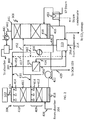
- Figs. 1 and 2 are exemplary schematic depictions of the system 100 for obtaining carbon dioxide at lower pressures from a chilled ammonia process.
- the system comprises an ammonia absorber system 200 for removing a majority of the carbon dioxide present in the flue gas stream that emanates from a combustion process and a wash system 300 that facilitates the recovering of ammonia slip that occurs in the chilled ammonia process.
- the absorber system 200 comprises a direct contact cooler 202 in fluid communication with an absorber 204.
- the absorber 204 receives a flue gas stream from a combustion process (or from a post-combustion process) that is substantially devoid of sulfur dioxide (SO 2 ), nitrogen oxides (NOx), and particulate matter from the direct contact cooler 202.
- SO 2 sulfur dioxide
- NOx nitrogen oxides
- the flue gas received at the absorber 204 contains a high percentage of carbon dioxide, which is to be extracted and reused for other purposes.
- the absorber 204 employs an absorbent solution (disposed therein) or slurry that facilitates the absorption and the removal of a gaseous component such as carbon dioxide from the flue gas stream.
- the absorbent solution in the main carbon dioxide absorber system 200 is a solution or slurry including ammonia.
- the ammonia can be in the form of an ammonium ion (NH 4 + ), ammonium carbamate, ammonium bicarbonate, or in the form of dissolved molecular ammonia (NH 3 ).
- the absorbent solution or slurry may be comprised of ammonium carbonate, carbamate and bicarbonate ions.
- the absorption of the acidic components such as carbon dioxide present in the flue gas stream is achieved when the absorber is operated at atmospheric pressure and at a low temperature, for example, between zero and thirty degrees Celsius (0-30°C.).
- absorption of the acidic component from flue gas stream is achieved when the absorber is operated at atmospheric pressure and at a temperature between zero and ten degrees Celsius (0-10°C.).
- the ammonia reacts with the carbon dioxide present in the flue gas to form ammonium carbonate, ammonium bicarbonate, ammonium carbamate, and the like and form a carbon dioxide lean flue gas stream.
- the process may generally be referred to as the main scrubbing process. After scrubbing, contaminants such as trace amounts of ammonia (also referred to as the ammonia slip) compounds and other degradation products remain in the carbon dioxide lean flue gas.
- the carbon dioxide lean flue gas with the contaminants is fed to a wash system 300, wherein the ammonia and other contaminants are removed from the carbon dioxide lean flue gas, which may then be discharged into the atmosphere or further processed within a direct contact heater (DCH) where residual ammonia is captured using acid such as sulfuric acid to form ammonium sulfate before discharging to the atmosphere via stack.
- DCH direct contact heater
- a rich-lean heat exchanger 216 Disposed between the absorber 204 and the regenerator 214 is a rich-lean heat exchanger 216 that transfers heat from the carbon dioxide lean ammonia solution leaving the regenerator 214 for the absorber 204 and the carbon dioxide rich ammonia solution leaving the absorber for the regenerator 214.
- the absorber 204, the rich-lean heat exchanger 216 and the regenerator 214 all lie upstream as well as downstream of each other. In other words, they are in a recycle loop.
- the chilled ammonia process to remove the carbon dioxide from the post combustion flue gas stream is detailed in US 8308849 B2 to Gal; US 8758493 B2 to Gal ; and US 2012/0258031 A1 to Guidolin et al. , the entire contents of which are hereby incorporated by reference.
- the regenerator 214 operates at a lower pressure of about 3 to 25 bar, preferably 4 to 20 bar, and more preferably 5 to 15 bar, which is lower than other conventionally operated regenerators. In an exemplary embodiment, the regenerator 214 operates from 3 to 15 bar.
- the carbon dioxide rich stream 252 is contacted by steam and generates a gaseous component (comprising mostly gaseous carbon dioxide) and an ammonia solution.
- the gaseous component containing carbon dioxide, traces of ammonia and water ends in the carbon dioxide wash station 310 while the liquid component, which contains a substantial amount of ammonia, returns to the absorber 204 after passing through rich-lean heat exchanger 216.
- the carbon dioxide is sequestered while an ammonia solution (obtained from the traces of ammonia) containing a first concentration of ammonia is discharged to the reverse osmosis system 318.
- the gaseous carbon dioxide, ammonia and water leave the top of the regenerator 214 and enter the carbon dioxide wash station 310.
- the liquid ammonia-carbon dioxide-water solution known as "lean" solution leaves from the bottom of the regenerator 214 and enters the absorber 204 after passing through rich-lean heat exchanger 216.
- the carbon dioxide wash station 310 most of the ammonia is captured and the water is condensed using cold re-circulating water. In this resulting solution, the maximum ammonia molarity allowed is approximately 1.5 M (molar).
- a clean carbon dioxide gas stream leaves from the carbon dioxide wash vessel (with less than 10 ppm ammonia) and is discharged to either a compressor or to a storage section or delivered to the client at that particular specification.
- the ammonia solution having a first concentration of ammonia is discharged from the carbon dioxide wash station 310 to the reverse osmosis system 318 via first stream 454 (having a first ammonia concentration) where it is processed into two streams - a second stream 456 (having a second ammonia concentration) and a third stream 458 (having a third ammonia concentration).
- Stream 458 contains a higher concentration of the ammonia (than the first concentration) and is discharged to the absorber 204 to interact with the flue gas stream as detailed above.
- Stream 456 has a lower ammonia concentration than stream 454 (i.e., than the first concentration) and is recharged to the carbon dioxide wash station 310 where the ammonia is captured.
- the stream 458 having the higher ammonia concentration is called the retentate stream while the stream having the lower ammonia concentration is called the permeate stream.
- a portion of this stream 456 may be recharged to the wash vessel 306 via streams 457 and 460.
- the wash system 300 comprises a wash vessel 306, an ammonia stripper column 308, a reverse osmosis system 318, a carbon dioxide wash station 310, a direct contact heater (DCH) 320 and a carbon dioxide compression and storage system 312.
- the wash vessel 306 and the stripper column 308 lie in a recycle loop.
- the carbon dioxide wash station 310 and the ammonia stripper system 308 lie in a recycle loop.
- the reverse osmosis system 318 is in a recycle loop with the carbon dioxide wash station 310.
- the reverse osmosis system 318 lies upstream of the absorber 204 of the absorption system 200. Purified carbon dioxide obtained from the carbon dioxide wash station 310 is discharged to a sequestration station 312 to be stored at a low pressure.
- Fig.s 1 and 2 show only a single reverse osmosis system 318, there can be a plurality of reverse osmosis devices connected in series or in parallel with one another to facilitate removal of the ammonia traces in the carbon dioxide gas stream received from the wash station.
- the wash system 300 is used to reduce ammonia slip while at the same time producing carbon dioxide at low pressures for other consumer applications. It is to be noted that there are two ammonia wash vessels. One is the wash vessel 306, which removes ammonia from the flue gas stream (entering from 204) and the other is the carbon dioxide wash station 310, which is much smaller in size and receives a stream (at pressures of 3 to 25 bar for removing ammonia from the carbon dioxide product) from regenerator 214.
- the Fig. 2 is an expanded exemplary schematic of the wash system 300 that is used to reduce ammonia slip while at the same time producing low pressure carbon dioxide.
- the wash vessel 306 generally includes one or more absorption stages. In the exemplary embodiment shown, the wash vessel includes a first absorption stage 409 and a second absorption stage 410.
- the wash vessel 306 is not limited in this regard as it is contemplated that the wash vessel may have more or less absorption stages.
- Each of the absorption stages may include a mass transfer device 412, a spray head system 414, and a liquid delivery path 416.
- the CO 2 lean flue gas 406 from the absorber enters the first absorption stage 409 at a bottom portion of the wash vessel 306. While the opening is shown at the bottom portion, it is contemplated that the CO 2 lean flue gas 406 may be at any point in the wash vessel and may vary from system to system depending on the application.
- the mass transfer device 412 may include packing, such as, for example, random packing, hydrophilic packing, and/or structural packing.
- Random packing is generally known in the art and refers to packing material introduced to the absorption stage in an un-organized fashion. Examples of random packing include, but are not limited to plastic, metal and/or ceramic packing material offered in different sizes, e.g., material having varying diameters, for example, diameters ranging between about 2.5 centimeters (2.5 cm) to about 7.6 centimeters (7.6 cm) (about 1 inch to about 3 inches). Random packing material is available from many suppliers, including, but not limited to Jaeger Products Inc. (Houston, Tex., United States). Random packing material may also include wood. Hydrophilic packing includes, but is not limited to polypropylene bags.
- Structural packing is generally known in the art and refers to packing material that is arranged or organized in a specific fashion. Typically, structural packing is arranged in a manner to force fluids to take a complicated path, thereby creating a large surface area for contact between the liquid and gas. Structural packing includes, but is not limited to structures made of metal, plastic, wood, and the like. It is contemplated that different packing materials facilitate ammonia removal or reduction at different flow rates of a liquid into the wash vessel 306. Additionally, it is contemplated that the different packing materials may provide more suitable pressure drops.
- one of the absorption stages 409 or 410 of the wash vessel 306 includes random packing material as the mass transfer device 412 and another of the absorption stages 409 or 410 of the wash vessel 306 includes structural packing as the mass transfer device.
- first absorption stage 409 may include random packing material as the mass transfer device 412
- second absorption stage 410 may include structural packing as the mass transfer device. It is contemplated that the carbon dioxide lean flue gas 406 enters the wash vessel 306 and passes through the first absorption stage 409 prior to passing through the second absorption stage 410.
- the mass transfer device 412 is located beneath the spray head system 414.
- Each of the spray head systems 414 in wash vessel 306 sprays a liquid onto the absorption stages 409, 410.
- the liquid is transported to the spray head system 414 via one of the liquid delivery paths 416.
- the liquid delivery paths 416 are conduits that transport the liquid to the respective spray head system 414.
- the liquid may be any liquid suitable to facilitate the removal of ammonia from the carbon dioxide lean flue gas 406.
- An example of a suitable liquid is water, which is known to absorb, i.e., dissolve, ammonia through interactions between the ammonia and the water.
- the liquid introduced to the second absorption stage 410 is liquid, e.g., water, provided by a stripping column 308. That is, water that has had all or substantially all of the ammonia as well as other contaminants contained therein removed and/or substantially removed.
- the liquid provided to the first absorption stage 409 is liquid 418 (also referred to as the washed liquid), which is water-containing a low concentration of ammonia recycled from the bottom of the wash vessel 306, which may be passed via pump 422 through an optional heat exchanger (not shown).
- the liquid is introduced at the top of each absorption stage 409, 410, e.g., liquid 418 is provided to the top of first absorption stage 409 and liquid from the stripper 308 is provided to the top of second absorption stage 410 of the wash vessel 306 (as the ammonia polishing stage).
- the liquid travels in a direction down a length of the wash vessel 306, which is countercurrent to a direction that the carbon dioxide lean flue gas 406 travels.
- the liquid travels in direction by virtue of gravity, while the carbon dioxide lean flue gas 406 travels in a countercurrent direction by virtue of several factors, including pressure drops within the wash vessel 306.
- the ammonia concentration in the liquid increases, thereby forming the ammonia-rich liquid 418.
- the carbon dioxide lean flue gas 406 travels in a direction up a length of the wash vessel 306, the ammonia concentration (as well as the concentration of the other water soluble contaminants) decreases, thereby forming a reduced ammonia-containing flue gas stream 424, which may be further treated such as being fed to a direct contact heater (DCH) 320 (See Fig. 1 ) and/or discharged into the atmosphere.
- DCH direct contact heater
- the amount of ammonia removed from the carbon dioxide lean flue gas 406 varies from system to system and application to application. It is also contemplated that the system be designed in a manner that the ammonia concentration in the reduced ammonia containing flue gas stream 424 is low and close to an equilibrium concentration of ammonia in the gas relative to the vapor pressure of the ammonia in the liquid.
- the equilibrium concentration of ammonia in the flue gas stream 424 may be as low as below ten parts per million (10 ppm) and typically in the range of between about zero parts per million (0 ppm) to about two hundred parts per million (200 ppm).
- the reduced ammonia containing flue gas stream 424 contains at least about seventy percent (70%) less ammonia as compared to a level of ammonia in the carbon dioxide lean flue gas 406. In another embodiment, the reduced ammonia containing flue gas stream 424 contains at least about seventy five percent (75%) less ammonia as compared to a level of ammonia in the carbon dioxide lean flue gas 406. In yet a further embodiment, the reduced ammonia containing flue gas stream 424 contains at least about eighty percent (80%) less ammonia as compared to a level of ammonia in the carbon dioxide lean flue gas 406.
- the reduced ammonia containing flue gas stream 424 contains at least about eighty five (85%) less ammonia as compared to a level of ammonia in the ammonia-containing flue gas stream 406. It is contemplated that the level of ammonia in the reduced ammonia containing flue gas stream 424 may be about ninety percent (90%), ninety five percent (95%), ninety nine percent (99%) or ninety nine and a half percent (99.5%) less than the level of ammonia in the carbon dioxide lean flue gas 406.
- An effective flow rate of liquid suitable to reduce the amount of ammonia in the flue gas varies from system to system.
- the flow rate is suitable to reduce an amount of ammonia in the flue gas to an amount close to the equilibrium concentration and typically to below two hundred parts per million (200 ppm) in the flue gas stream.
- the flow rate is suitable to reduce an amount of ammonia in the flue gas from about two thousand parts per million (2000 ppm) to between about seventy parts per million and about one hundred parts per million (70-100 ppm).
- the flow rate of the liquid is between about 1.8 liters per minute (1.8 Ipm, or about 0.5 gallons per minute) to about 7.5 liters per minute (7.5 Ipm or about 2 gallons per minute) per one thousand cubic feet per minute (1000 cfm) of flue gas.
- the liquid flow rate can be adjusted to the desired ammonia slip level from the wash vessel.
- the liquid falls to the bottom of the wash vessel 306 and is removed therefrom as ammonia-rich liquid 418.
- a portion of the ammonia-rich liquid 418 may be recycled to the wash vessel 306 as liquid and a portion of the ammonia-rich liquid is charged to the stripping column 308 via stream 452. Additionally, while not shown, it is contemplated that the entire amount of the ammonia-rich liquid 418 may be sent to the stripping column 308 and then returned to the wash vessel 306.
- the ammonia rich liquid 418 may be fed to an optional heat exchanger (not shown) before being discharged to the stripping column 308.
- a carbon dioxide loaded solution (slip stream) is sent from the carbon dioxide wash station 310 to the absorber 204 (See stream 462 in the Fig. 1 ) to reduce the ammonia slip.
- a clean water solution 438 from the stripper 308 is sent to the carbon dioxide wash water via stream 435 as shown in Fig. 2 to maintain the mass balance and the ammonia molarity in the carbon dioxide wash water.
- the stripping column 308 utilizes steam from reboiler 450 to remove the ammonia and the other contaminants from the increased molarity ammonia-rich fluid stream 430 as well as stream 452 (which is transported from the wash vessel 306) to form the ammonia lean liquid 438 that can then be recycled to the wash vessel 306 or fed to the direct contact cooler or direct contact heater as may be desired in some applications. Recycling to the wash vessel 306 generally includes reducing the temperature ammonia lean liquid 438 by feeding through heat exchanger 436 and then through chiller (not shown) prior to introduction into the wash vessel 306.
- the stripping column 308 may utilize other technology or techniques in order to remove the ammonia and other contaminants from the increased molarity ammonia-rich fluid stream 430 as well as stream 452.
- the increased molarity ammonia-rich fluid stream 430 may be mixed with lean solution 452 used in the absorber (ammonia solution or slurry) prior to introduction into the stripper to further increase the ammonia concentration of the liquid being fed to the stripper column 308 so as to further reduce the energy requirements of the stripper system.
- the stripping column 308 may be operated at vacuum conditions to reduce the temperature of the steam utilized in the stripping column.
- the slip stream (lean solution) from the absorber-regenerator loop is processed via an appendix stripper (not shown) to maintain the water balance within the process.
- the appendix stripper bottom is sent to the direct contact cooling or direct contact heating (DCC/DCH) section and the top portion which contains ammonia and CO 2 is sent to the absorber.
- DCC/DCH direct contact cooling or direct contact heating
- the additional appendix stripper for water balance is advantageously not needed and the slip stream from the absorber-regenerator loop can be combined directly with the nanofiltration or reverse osmosis retentate (assuming it will have the same ammonia molarity as the lean solution from the absorber-regenerator loop) before processing through stripper.
- the extra water from the stripper can be sent from the bottom portion of stripper 308 to the DCC/DCH section via conduit 439 as shown in Figs. 1 and 2 .
- the operation of the regenerator 214 at lower pressures of 3 to 25 bar produces carbon dioxide at the lower pressure of 3 to 25 bar. While this carbon dioxide is desirable to consumers, the production of this low pressure carbon dioxide is accompanied by the presence of increased amounts of ammonia when compared with conventional high pressure operation of the regenerator 214. It is therefore desirable to remove this excess generated ammonia.
- this is accomplished by discharging a carbon dioxide gas stream 256 that contains traces of ammonia to the water wash system 310.
- a carbon dioxide gas stream 256 that contains traces of ammonia
- the maximum ammonia molarity allowed is approximately 1.5 M (molar).
- a wash solution from the carbon dioxide wash station that contains traces of ammonia is discharged to the reverse osmosis system 318.
- the wash solution from the water wash system 454 that contains ammonia is physically separated into two feed streams 456 and 458.
- feed stream 458 the ammonia concentration is increased relative to the ammonia concentration of the wash solution stream 454 to form an increased molarity ammonia rich liquid stream (i.e., retentate), whereas in feed stream 456, the ammonia concentration is decreased relative to the ammonia concentration of the wash solution stream 454 to form a decreased molarity ammonia rich liquid stream (i.e., permeate).
- the wash solution stream 454 has an ammonia concentration of up to 1.5 M, while the retentate (feed stream 458) has an ammonia concentration of greater than 1.5 M to 8 M.
- the retentate stream 458 having the higher ammonia concentration is charged to the absorber 204. This reduces the amount of energy used by the stripper 308.
- the permeate stream 456 having the lower ammonia concentration is charged back to the carbon dioxide wash station 310 where it may be combined with stream 430 and treated in the stripping column 308.
- a portion of the permeate stream 456 may be recharged to the wash vessel 306 via streams 457 and 460.
- the wash station 306 captures ammonia slip from the outgoing flue gases from the absorber 204 (See Fig. 1 )
- the fluid stream 440 including the recovered ammonia fluid and other volatile contaminants is discharged from a top portion 441 of the stripper column 308, cooled via chiller 442 and recycled to the absorber and/or recycled back to the stripper column 308.
- the recovered ammonia fluid stream 440 may be recycled for use in the absorber as an ammoniated solution.
- the ammonia may be utilized at other points inside and outside of system 100.
- Pure carbon dioxide obtained from the regenerator 214 at the lower pressures specified above may be discharged to storage 312 (See Fig. 1 ) for sequestration or alternatively, for repackaging and sale to consumers.
- storage 312 See Fig. 1
- a significant amount of saving on the overall electrical energy associated with power plant steam extraction can be achieved in cases where the carbon dioxide product is to be used at lower pressure.
- another arrangement disclosed herein pertains to a combination of an absorber, a regenerator and a reverse osmosis system in which the reverse osmosis system is fed with a portion of the carbon dioxide rich stream from the absorber.
- the permeate from the reverse osmosis system is returned to the absorber, while the retentate is charged to the regenerator. This reduces the capital and operating cost of the plant significantly.
- Fig. 3 shows a depiction of this system 700.
- the reverse osmosis system 318 lies downstream of the absorber 204 and upstream of the regenerator 214.
- a portion of the carbon dioxide rich stream from the absorber 204 is charged to the reverse osmosis system 318 via stream 502.
- the carbon dioxide rich stream is pressurized to overcome the osmotic pressure of the solution.
- the purpose is to separate the water and some portion of the ionic absorbent from the carbon dioxide rich solution before it goes to the regenerator 214 by using membrane separation technology and in turn reduce the capital and operating cost of the plant significantly.
- the permeate (with molecular ammonia, small amount of ionic ammonia and water) is recharged to the absorber via stream 504 and is used to absorb carbon dioxide from the incoming flue gas stream 406.
- the retentate (the stream that contains higher amount of ammonia than the stream 502 such as ammonium bicarbonate, ammonium carbonate, ammonium carbamate, and the like) is charged to the regenerator 214 via stream 506.
- the regenerator 214 the retentate is dissociated into carbon dioxide gas which is compressed and transported to customers.
- the ammonia solution from the regenerator is returned to the absorber to absorb more carbon dioxide from the flue gas stream 406.
- transition term comprising encompasses the transition terms "consisting of” and “consisting essentially of”.
- relative terms such as “lower” or “bottom” and “upper” or “top,” may be used herein to describe one element's relationship to another element as illustrated in the Figures. It will be understood that relative terms are intended to encompass different orientations of the device in addition to the orientation depicted in the Figures. For example, if the device in one of the figures is turned over, elements described as being on the “lower” side of other elements would then be oriented on “upper” sides of the other elements. The exemplary term “lower,” can therefore, encompasses both an orientation of “lower” and “upper,” depending on the particular orientation of the figure.
- Exemplary embodiments are described herein with reference to cross section illustrations that are schematic illustrations of idealized embodiments. As such, variations from the shapes of the illustrations as a result, for example, of manufacturing techniques and/or tolerances, are to be expected. Thus, embodiments described herein should not be construed as limited to the particular shapes of regions as illustrated herein but are to include deviations in shapes that result, for example, from manufacturing. For example, a region illustrated or described as flat may, typically, have rough and/or nonlinear features. Moreover, sharp angles that are illustrated may be rounded. Thus, the regions illustrated in the figures are schematic in nature and their shapes are not intended to illustrate the precise shape of a region and are not intended to limit the scope of the present claims.
Landscapes
- Chemical & Material Sciences (AREA)
- Engineering & Computer Science (AREA)
- Chemical Kinetics & Catalysis (AREA)
- Analytical Chemistry (AREA)
- General Chemical & Material Sciences (AREA)
- Oil, Petroleum & Natural Gas (AREA)
- Environmental & Geological Engineering (AREA)
- Health & Medical Sciences (AREA)
- Biomedical Technology (AREA)
- Organic Chemistry (AREA)
- Inorganic Chemistry (AREA)
- Life Sciences & Earth Sciences (AREA)
- Sustainable Development (AREA)
- Gas Separation By Absorption (AREA)
- Treating Waste Gases (AREA)
Applications Claiming Priority (1)
| Application Number | Priority Date | Filing Date | Title |
|---|---|---|---|
| US14/677,238 US9573816B2 (en) | 2015-04-02 | 2015-04-02 | System for low pressure carbon dioxide regeneration in a chilled ammonia process |
Publications (1)
| Publication Number | Publication Date |
|---|---|
| EP3075431A1 true EP3075431A1 (de) | 2016-10-05 |
Family
ID=56072184
Family Applications (1)
| Application Number | Title | Priority Date | Filing Date |
|---|---|---|---|
| EP16163426.6A Withdrawn EP3075431A1 (de) | 2015-04-02 | 2016-03-31 | System zur herstellung von niederdruck-kohlenstoffdioxid in einem gekühlten ammoniakverfahren |
Country Status (2)
| Country | Link |
|---|---|
| US (1) | US9573816B2 (de) |
| EP (1) | EP3075431A1 (de) |
Cited By (1)
| Publication number | Priority date | Publication date | Assignee | Title |
|---|---|---|---|---|
| WO2018114369A1 (en) * | 2016-12-22 | 2018-06-28 | General Electric Technology Gmbh | System and method for recovering ammonia from a gas stream |
Families Citing this family (3)
| Publication number | Priority date | Publication date | Assignee | Title |
|---|---|---|---|---|
| US11161076B1 (en) * | 2020-08-26 | 2021-11-02 | Next Carbon Solutions, Llc | Devices, systems, facilities, and processes of liquid natural gas processing for power generation |
| US11852376B2 (en) * | 2022-03-15 | 2023-12-26 | Next Carbon Solutions, Llc | Devices, systems, facilities and processes for CO2 capture/sequestration and direct air capture |
| WO2024153464A1 (en) * | 2023-01-19 | 2024-07-25 | Nuovo Pignone Tecnologie - S.R.L. | Carbon dioxide recovery and conditioning system and method for ammonia-based carbon dioxide capture processes |
Citations (6)
| Publication number | Priority date | Publication date | Assignee | Title |
|---|---|---|---|---|
| US20120180521A1 (en) * | 2011-01-18 | 2012-07-19 | Erickson Donald C | Flue Gas Scrubbing with Aqueous Ammonia |
| US20120258031A1 (en) | 2011-04-06 | 2012-10-11 | Alstom Technology Ltd. | Carbon dioxide capture system |
| US8308849B2 (en) | 2004-08-06 | 2012-11-13 | Alstom Technology Ltd | Ultra cleaning of combustion gas including the removal of CO2 |
| US20130092026A1 (en) * | 2011-10-18 | 2013-04-18 | Alstom Technology Ltd. | Chilled ammonia based co2 capture system with wash system and processes of use |
| US8758493B2 (en) | 2008-10-02 | 2014-06-24 | Alstom Technology Ltd | Chilled ammonia based CO2 capture system with water wash system |
| EP2829311A1 (de) * | 2013-07-25 | 2015-01-28 | Alstom Technology Ltd | Ammoniakstripper für ein Kohlenstoffabscheidungssystem zur Reduzierung des Energieverbrauchs |
Family Cites Families (11)
| Publication number | Priority date | Publication date | Assignee | Title |
|---|---|---|---|---|
| DE19808433A1 (de) | 1998-03-02 | 1999-09-09 | Fresenius | Verfahren und Vorrichtung zur Entfernung oder Reduzierung des Ammonium-Anteils aus Abwässern |
| JP3969949B2 (ja) | 2000-10-25 | 2007-09-05 | 関西電力株式会社 | アミン回収方法及び装置並びにこれを備えた脱炭酸ガス装置 |
| EA013218B1 (ru) | 2004-12-08 | 2010-04-30 | ДСМ АйПи АССЕТС Б.В. | Способ извлечения аммиака из потока газа, содержащего аммиак |
| EP2144689A1 (de) | 2007-05-09 | 2010-01-20 | Powerspan Corp. | Kohlendioxidspülung mit ammoniumcarbonat und ammoniakdampfkontrolle |
| US7981196B2 (en) | 2007-06-04 | 2011-07-19 | Posco | Apparatus and method for recovering carbon dioxide from flue gas using ammonia water |
| KR20100038204A (ko) | 2007-06-22 | 2010-04-13 | 커먼웰쓰 사이언티픽 앤드 인더스트리얼 리서치 오가니제이션 | 가스 흐름들에서부터 암모니아 용액들로 co2 전달을 위한 개선된 방법 |
| US8182577B2 (en) | 2007-10-22 | 2012-05-22 | Alstom Technology Ltd | Multi-stage CO2 removal system and method for processing a flue gas stream |
| US20110052453A1 (en) | 2008-01-18 | 2011-03-03 | Mclarnon Christopher | Removal of carbon dioxide from a flue gas stream |
| US8007570B2 (en) | 2009-03-11 | 2011-08-30 | General Electric Company | Systems, methods, and apparatus for capturing CO2 using a solvent |
| US8551221B2 (en) | 2009-11-02 | 2013-10-08 | Thomas D. Wolfe | Method for combining desalination and osmotic power with carbon dioxide capture |
| US8328911B2 (en) | 2010-06-21 | 2012-12-11 | The University Of Kentucky Research Foundation | Method for removing CO2 from coal-fired power plant flue gas using ammonia as the scrubbing solution, with a chemical additive for reducing NH3 losses, coupled with a membrane for concentrating the CO2 stream to the gas stripper |
-
2015
- 2015-04-02 US US14/677,238 patent/US9573816B2/en active Active
-
2016
- 2016-03-31 EP EP16163426.6A patent/EP3075431A1/de not_active Withdrawn
Patent Citations (6)
| Publication number | Priority date | Publication date | Assignee | Title |
|---|---|---|---|---|
| US8308849B2 (en) | 2004-08-06 | 2012-11-13 | Alstom Technology Ltd | Ultra cleaning of combustion gas including the removal of CO2 |
| US8758493B2 (en) | 2008-10-02 | 2014-06-24 | Alstom Technology Ltd | Chilled ammonia based CO2 capture system with water wash system |
| US20120180521A1 (en) * | 2011-01-18 | 2012-07-19 | Erickson Donald C | Flue Gas Scrubbing with Aqueous Ammonia |
| US20120258031A1 (en) | 2011-04-06 | 2012-10-11 | Alstom Technology Ltd. | Carbon dioxide capture system |
| US20130092026A1 (en) * | 2011-10-18 | 2013-04-18 | Alstom Technology Ltd. | Chilled ammonia based co2 capture system with wash system and processes of use |
| EP2829311A1 (de) * | 2013-07-25 | 2015-01-28 | Alstom Technology Ltd | Ammoniakstripper für ein Kohlenstoffabscheidungssystem zur Reduzierung des Energieverbrauchs |
Cited By (1)
| Publication number | Priority date | Publication date | Assignee | Title |
|---|---|---|---|---|
| WO2018114369A1 (en) * | 2016-12-22 | 2018-06-28 | General Electric Technology Gmbh | System and method for recovering ammonia from a gas stream |
Also Published As
| Publication number | Publication date |
|---|---|
| US20160289080A1 (en) | 2016-10-06 |
| US9573816B2 (en) | 2017-02-21 |
Similar Documents
| Publication | Publication Date | Title |
|---|---|---|
| US10427948B2 (en) | Systems and methods for ammonia recovery, acid gas separation, or combination thereof | |
| EP2780099B1 (de) | Co2 abtrennungssystem basierend auf gekühltem ammoniak mit waschsystem und verfahren zur verwendung | |
| EP2412424B1 (de) | Kohlendioxidabscheidungssystem und verfahren zur kohlendioxidabscheidung | |
| US9295940B2 (en) | Configurations and methods for high pressure acid gas removal in the production of ultra-low sulfur gas | |
| EP3075431A1 (de) | System zur herstellung von niederdruck-kohlenstoffdioxid in einem gekühlten ammoniakverfahren | |
| US7749309B2 (en) | Method for deacidifying a fluid stream and washing liquid used in such a method | |
| US9216380B1 (en) | Ammonia stripper for a carbon capture system for reduction of energy consumption | |
| AU2009284712A1 (en) | Treatment of CO2-depleted flue gases | |
| KR20130056329A (ko) | Co₂ 포획 시스템의 에너지 요구량을 감소시키기 위한 방법 및 시스템 | |
| CN107073388B (zh) | 用于二氧化碳捕集的节能溶剂的再生方法 | |
| KR20130069818A (ko) | 반투과성 막에 의한 co₂제거 프로세스에서의 추적 성분 제거 | |
| US10213728B2 (en) | Method for separating carbon dioxide from a gas flow, in particular from a flue gas flow, and separating device for separating carbon dioxide from a gas flow, in particular from a flue gas flow | |
| US20160166977A1 (en) | Gas-assisted stripping of liquid solvents for carbon capture | |
| EA032340B1 (ru) | Способ извлечения диоксида углерода из абсорбента с уменьшенной подачей отгоночного пара | |
| WO2023113600A1 (en) | Method for chemical absorption and recovery of co2 with low energy consumption at low temperatures |
Legal Events
| Date | Code | Title | Description |
|---|---|---|---|
| PUAI | Public reference made under article 153(3) epc to a published international application that has entered the european phase |
Free format text: ORIGINAL CODE: 0009012 |
|
| AK | Designated contracting states |
Kind code of ref document: A1 Designated state(s): AL AT BE BG CH CY CZ DE DK EE ES FI FR GB GR HR HU IE IS IT LI LT LU LV MC MK MT NL NO PL PT RO RS SE SI SK SM TR |
|
| AX | Request for extension of the european patent |
Extension state: BA ME |
|
| 17P | Request for examination filed |
Effective date: 20170405 |
|
| RBV | Designated contracting states (corrected) |
Designated state(s): AL AT BE BG CH CY CZ DE DK EE ES FI FR GB GR HR HU IE IS IT LI LT LU LV MC MK MT NL NO PL PT RO RS SE SI SK SM TR |
|
| 17Q | First examination report despatched |
Effective date: 20180115 |
|
| STAA | Information on the status of an ep patent application or granted ep patent |
Free format text: STATUS: THE APPLICATION IS DEEMED TO BE WITHDRAWN |
|
| 18D | Application deemed to be withdrawn |
Effective date: 20180526 |