EP3073629A1 - Power conversion device and control method for permanent magnet synchronous motor - Google Patents
Power conversion device and control method for permanent magnet synchronous motor Download PDFInfo
- Publication number
- EP3073629A1 EP3073629A1 EP13897884.6A EP13897884A EP3073629A1 EP 3073629 A1 EP3073629 A1 EP 3073629A1 EP 13897884 A EP13897884 A EP 13897884A EP 3073629 A1 EP3073629 A1 EP 3073629A1
- Authority
- EP
- European Patent Office
- Prior art keywords
- synchronous motor
- magnetic pole
- pole position
- power conversion
- conversion device
- Prior art date
- Legal status (The legal status is an assumption and is not a legal conclusion. Google has not performed a legal analysis and makes no representation as to the accuracy of the status listed.)
- Granted
Links
- 230000001360 synchronised effect Effects 0.000 title claims abstract description 143
- 238000006243 chemical reaction Methods 0.000 title claims abstract description 83
- 238000000034 method Methods 0.000 title claims description 10
- 238000001514 detection method Methods 0.000 claims abstract description 20
- 230000006870 function Effects 0.000 claims description 26
- 230000002159 abnormal effect Effects 0.000 claims description 17
- 230000005856 abnormality Effects 0.000 claims description 7
- 230000004907 flux Effects 0.000 description 22
- 230000000977 initiatory effect Effects 0.000 description 18
- 238000010586 diagram Methods 0.000 description 13
- 238000012545 processing Methods 0.000 description 8
- 239000000470 constituent Substances 0.000 description 5
- 239000003990 capacitor Substances 0.000 description 4
- 238000009499 grossing Methods 0.000 description 4
- 238000001816 cooling Methods 0.000 description 3
- 238000004804 winding Methods 0.000 description 3
- 229910002601 GaN Inorganic materials 0.000 description 2
- JMASRVWKEDWRBT-UHFFFAOYSA-N Gallium nitride Chemical compound [Ga]#N JMASRVWKEDWRBT-UHFFFAOYSA-N 0.000 description 2
- 230000008901 benefit Effects 0.000 description 2
- 239000002131 composite material Substances 0.000 description 2
- 238000012790 confirmation Methods 0.000 description 2
- 230000005284 excitation Effects 0.000 description 2
- 238000012423 maintenance Methods 0.000 description 2
- HBMJWWWQQXIZIP-UHFFFAOYSA-N silicon carbide Chemical compound [Si+]#[C-] HBMJWWWQQXIZIP-UHFFFAOYSA-N 0.000 description 2
- 229910010271 silicon carbide Inorganic materials 0.000 description 2
- XUIMIQQOPSSXEZ-UHFFFAOYSA-N Silicon Chemical compound [Si] XUIMIQQOPSSXEZ-UHFFFAOYSA-N 0.000 description 1
- 230000008859 change Effects 0.000 description 1
- 238000004891 communication Methods 0.000 description 1
- 230000009977 dual effect Effects 0.000 description 1
- 230000000694 effects Effects 0.000 description 1
- 238000009434 installation Methods 0.000 description 1
- 238000005457 optimization Methods 0.000 description 1
- 230000009467 reduction Effects 0.000 description 1
- 239000004065 semiconductor Substances 0.000 description 1
- 229910052710 silicon Inorganic materials 0.000 description 1
- 239000010703 silicon Substances 0.000 description 1
Images


Classifications
-
- H—ELECTRICITY
- H02—GENERATION; CONVERSION OR DISTRIBUTION OF ELECTRIC POWER
- H02P—CONTROL OR REGULATION OF ELECTRIC MOTORS, ELECTRIC GENERATORS OR DYNAMO-ELECTRIC CONVERTERS; CONTROLLING TRANSFORMERS, REACTORS OR CHOKE COILS
- H02P6/00—Arrangements for controlling synchronous motors or other dynamo-electric motors using electronic commutation dependent on the rotor position; Electronic commutators therefor
- H02P6/14—Electronic commutators
- H02P6/16—Circuit arrangements for detecting position
- H02P6/18—Circuit arrangements for detecting position without separate position detecting elements
-
- H—ELECTRICITY
- H02—GENERATION; CONVERSION OR DISTRIBUTION OF ELECTRIC POWER
- H02P—CONTROL OR REGULATION OF ELECTRIC MOTORS, ELECTRIC GENERATORS OR DYNAMO-ELECTRIC CONVERTERS; CONTROLLING TRANSFORMERS, REACTORS OR CHOKE COILS
- H02P1/00—Arrangements for starting electric motors or dynamo-electric converters
- H02P1/02—Details
- H02P1/029—Restarting, e.g. after power failure
-
- H—ELECTRICITY
- H02—GENERATION; CONVERSION OR DISTRIBUTION OF ELECTRIC POWER
- H02P—CONTROL OR REGULATION OF ELECTRIC MOTORS, ELECTRIC GENERATORS OR DYNAMO-ELECTRIC CONVERTERS; CONTROLLING TRANSFORMERS, REACTORS OR CHOKE COILS
- H02P2203/00—Indexing scheme relating to controlling arrangements characterised by the means for detecting the position of the rotor
- H02P2203/03—Determination of the rotor position, e.g. initial rotor position, during standstill or low speed operation
Definitions
- the present invention relates to a power conversion device and a control method for a permanent magnet synchronous motor.
- Patent Literature 1 discloses a magnetic pole detection method that derives a current phase at an absolute scale absolute position at the time of power-on by calculation from relation between the absolute scale absolute position and the current phase stored in a storage device.
- Patent Literature 1 JP-A-2007-116759
- the magnetic pole position of the permanent magnet synchronous motor is estimated using information on current and voltage of the permanent magnet synchronous motor.
- current and voltage become zero and information cannot be obtained, thereby causing information on the magnetic pole position estimated up until that point to be lost; therefore, there is a need for means to estimate the magnetic pole position each time when the permanent magnet synchronous motor is restarted.
- Patent Literature 1 discloses that "in synchronous motor magnetic pole detection methods for determining a current phase to be applied on the basis of a provisional magnetic pole position which is a startup position, provided is a magnetic pole detection method that stores in a storage device an absolute scale absolute position after magnetic pole position estimation and a current phase at that position, as a current phase at an absolute scale absolute position or an absolute scale absolute position at a current phase, and derives a current phase at the absolute scale absolute position at the time of power-on by calculation from relation between the absolute scale absolute position and the current phase stored in the storage device from the time of next power-on.”
- an absolute encoder which is a magnetic pole position sensor, is indispensable, and it is installed at the side opposite to a load of a synchronous motor.
- the encoder When an encoder is installed at a motor, the encoder must be installed at the side opposite to the load of the motor, and therefore a dual-shaft motor is required; consequently, there arise problems such as securing an installation place due to increase in the size of the motor including the encoder, an erroneous signal due to noise mixed in encoder output, and necessity for a dual shaft-processed special motor.
- the present invention aims for providing a configuration that enables a user to select means for identifying the magnetic pole position depending on the system configuration.
- a power conversion device that comprises a power conversion unit for converting direct current into alternating current and that performs variable speed control of a synchronous motor in which a permanent magnet is used has a configuration that comprises: a current detection circuit for detecting current flowing through the synchronous motor; estimation means for estimating a magnetic pole position of the synchronous motor at a startup of the synchronous motor; and a memory for storing magnetic pole position estimation data indicating a magnetic pole position at a stop of the synchronous motor, and that comprises: selection means for selecting magnetic pole position estimation data stored in the memory or magnetic pole position estimation data obtained by the estimation means; and a control unit for driving the synchronous motor using the magnetic pole position estimation data selected by the selection means.
- the present invention enables reduction in a magnetic pole position estimation time by using different magnetic pole position estimation data depending on a system.
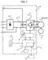
- Fig. 1 is an example of a configuration diagram of the power conversion device according to Embodiment 1.
- a power conversion device 10 in Fig. 1 comprises a forward converter 1 for supplying power to a PM motor (hereinafter called a permanent magnet synchronous motor) directly coupled onto a load device 11, a smoothing capacitor 2, an inverse converter 3, a control arithmetic device 4, a control circuit 5, a cooling fan 6, a digital operation panel 7, a drive circuit 8, and a voltage detection circuit 9.
- Fig. 1 shows the case of using an AC power supply as any input power supply.
- the forward converter 1 converts AC power to DC power.
- the smoothing capacitor 2 is comprised in a DC intermediate circuit.
- the inverse converter 3 converts DC power into AC power with any frequency.
- a typical switching element for example, an IGBT is mounted inside the inverse converter 3.
- the switching element is not limited to an IGBT, and any thing is sufficient as long as it has a form as a switching element.
- it may be SiC (Silicon Carbide) or GaN (Gallium Nitride), which is a wide-band gap semiconductor element having performance overleaping the solid-state property value limit of Silicon (Si).
- the cooling fan 6 takes the heat from power modules in the forward converter 1 and the inverse converter 3.
- the digital operation panel 7 performs setting and changing of various control data of the power conversion device and displaying of an abnormal state and a monitor state.
- the operation panel 7 is provided with a display unit capable of abnormality display, and abnormality is displayed on the display unit when the abnormality in the power conversion device is detected.
- the operation panel 7 in the embodiment is not limited to a particular type, but taking operability for a device user into consideration, as a digital operation panel, it has a configuration such that the user can operate it while looking at the display on the display unit.
- the display unit does not necessarily need to have an integral structure with the operation panel 7, but it is desirable to have the integral structure so as to enable an operator of the operation panel 7 to operate it while looking at the display.
- Various control data of the power conversion device input from the operation panel 7 is stored in an unshown storage unit.
- the control circuit 5 controls a switching element of the inverse converter 3 on the basis of various control data input by the digital operation panel 7, and serves to manage control of the whole power conversion device 10.
- the control circuit 5 is equipped with the control arithmetic device 4 (for example, a microcomputer) and configured to be able to perform control processing necessary according to various control data input by the digital operation panel 7. In addition, it is also configured to be able to perform control processing necessary according to various control data input from an upper-level device 12 (for example, a communication device or radio device).
- an upper-level device 12 for example, a communication device or radio device.
- CTs detect line current of the U phase and W phase of the permanent magnet synchronous motor.
- Fig. 1 shows an example of using two CTs, but three CTs may be used and line current of each of the U phase, V phase and W phase may be detected.
- the drive circuit 8 drives the switching element of the inverse converter 3 on the basis of a command from the control circuit 5.
- a switching regulator circuit DC/DC converter
- the DC voltage detection circuit 9 detects voltage of the smoothing capacitor 2 forming the DC intermediate circuit.
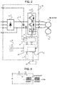
- Fig. 2 is an example of another configuration diagram. In the same way as the configuration example in Fig. 1 , it is able to perform below-described control. Constituents common to and the same functions as Fig. 1 are given the same reference numerals. Difference from Fig. 1 is the detection positions of current detectors.
- SH1 and SHd are shunt resistors for current detection, SH1 detects current at the N side of the DC intermediate circuit, SHi is connected with IGBTs of the U phase, V phase and W phase, which are switching elements of a lower arm constituting part of the inverse converter 3, and SHd is connected with diodes connected in parallel with the respective IGBTs which are switching elements.
- the shunt resistor SHi provided at a DC bus bar side of the power conversion device is a current detector for detecting composite current flowing through the IGBTs
- the shunt resistor SHd provided at the DC bus bar side of the power conversion device is a current detector for detecting composite current flowing through the diodes connected in parallel with the respective IGBTs.
- the shunt resistors provided at the DC bus bar side of the power conversion device are able to detect current flowing through the permanent magnet synchronous motor.
- shunt resistors SHi and SHd are connected with the IGBT and the diode, respectively, in the lower arm constituting part of the U phase, but they may be connected with an IGBT and a diode, respectively, in an upper arm constituting part of the U phase to detect current.
- Fig. 3 is a simple equivalent circuit of the permanent magnet synchronous motor driven by the power conversion device in the embodiment. It consists of armature resistance Ra, armature inductance La, armature current Ia, speed electromotive force Ea, and magnetic flux of a permanent magnet ⁇ m.
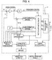
- Fig. 4 is a control block diagram of the power conversion device according to the embodiment. This shows a control block that is inside the control circuit 5 disclosed in Figs. 1 and 2 , and that is a partial processing block performed by the control arithmetic device 4 (for example, a microcomputer).
- the control arithmetic device 4 for example, a microcomputer
- the direction of magnetic flux generated by the magnet is estimated by a magnetic pole position estimation circuit without using a magnetic pole position sensor.
- T ⁇ m*I*sin ⁇
- the armature current Ia corresponds to a torque current component Iq.
- the current detectors CTs detect the line current of the permanent magnet synchronous motor, a dq-axis conversion unit converts the detected current into current in orthogonal "d” and "q" axes, and the resulting current is decomposed into an excitation current component Id and a torque current component Iq.
- the armature current Ia flowing through the permanent magnet synchronous motor is controlled as a torque current component Iq by operation of a q-axis current control system.
- the armature current Ia flowing through the permanent magnet synchronous motor can be operated as a torque current component proportional to the generation torque of the motor.
- the phase of the armature current Ia flowing through the permanent magnet synchronous motor should be controlled to 90° or more ( ⁇ >90°).
- detecting the magnetic pole position each time at a startup causes an increased tact time in the case of load applications that frequently repeat a start and a stop, and is not a desirable estimation mode.
- the motor does not rotate through inertia nor is rotated by a load after a stop because the brake is applied without fail when the motor is stopped; therefore, the magnetic pole position detected through estimation is not changed. Consequently, it is not necessary to detect the magnetic pole position each time before initiating a startup from a stop state, and it is possible to start the permanent magnet synchronous motor using magnetic pole position estimation data at the time point of a stop after initiating the startup.
- the magnetic pole position estimation data is simply stored in the memory (for example, a RAM), but in the case where power supply is cut off, if the data is only stored in the memory, the estimated information on the magnetic pole position will be lost when power supply is cut off. Consequently, the magnetic pole position at the time of a stop after initiating a startup is stored in a nonvolatile memory each time when power supply is cut off.
- a nonvolatile memory each time when power supply is cut off.
- Storing the data in the memory is processed by the control arithmetic circuit device 4 (for example, a microcomputer) according to a command from the digital operation panel 7 or the upper-level device 12.
- the control arithmetic circuit device 4 for example, a microcomputer
- Fig. 11 is an explanatory diagram of magnetic pole position detection according to the embodiment.
- (c) shows an explanatory diagram of what the detected magnetic pole position is a position on the basis of.
- An angle ⁇ of a magnetic pole position detected on the basis of the U phase of an armature winding of a three-phase permanent magnet synchronous motor is determined.
- the angle ⁇ of the magnetic pole position is set as the "d" axis on control, and a right angle direction to the "d" axis is set as the "q" axis on control.
- the detected magnetic pole position is the angle ⁇ (direction of the magnetic flux ⁇ m) on the basis of the U phase of the armature winding, and the angle ⁇ of the magnetic pole position (magnetic pole position estimation data) is stored in the memory.
- the explanation is given on the basis of the U phase of the armature winding, but the basis may be the V phase or the W phase.
- an imaginary reference axis may be set, and the angle ⁇ of the magnetic pole position detected on the basis of that axis may be determined.
- control arithmetic device 4 (for example, a microcomputer) inside the power conversion device detects the magnetic pole position of the synchronous motor, and controls the synchronous motor according to the detected value; therefore, it always recognizes the magnetic pole position of the synchronous motor. In other words, the control arithmetic device 4 always recognizes which angle ⁇ the magnetic pole position is while the synchronous motor is rotating controlled by the power conversion device. Consequently, the control arithmetic device 4 also recognizes the angle ⁇ of the magnetic pole position at the time point when the synchronous motor is stopped.
- the control arithmetic device 4 cannot get hold of the actual magnetic pole position of the synchronous motor.
- the explanation is given of making the angle ⁇ into the magnetic pole position on the basis of the U phase, but there are many methods for detecting the magnetic pole position (direction of the magnetic flux ⁇ m). Therefore, the example is only one example, and does not limit determination methods for the magnetic pole position (direction of the magnetic flux ⁇ m) or the angle ⁇ of the magnetic pole position. In fact, the angle ⁇ of the magnetic pole position may be not an actual angle as long as it can define the position of the magnetic pole.
- a magnetic pole position (direction of the magnetic flux ⁇ m) ⁇ m0 is a first magnetic pole position (initial magnetic pole position) detected at a first startup.
- angles of the magnetic pole positions at a motor stop 0 (initial magnetic pole position), motor stop B, motor stop C, motor stop D, motor stop E, i.e. an angle ⁇ 0 for the time point of motor stop 0, an angle ⁇ B for the time point of motor stop B, an angle ⁇ C for the time point of motor stop C, an angle ⁇ D for the time point of motor stop D, and an angle ⁇ E for the time point of motor stop E are stored in the memory, and when the motor is started from the respective time points of stop, as long as it is started using the corresponding magnetic pole position estimation data stored in the memory, the motor does not go out of control.
- the magnetic pole position estimation data ⁇ 0 when it is started from the time point of motor stop 0 the magnetic pole position estimation data ⁇ A when it is started from the time point of motor stop A, the magnetic pole position estimation data ⁇ B when it is started from the time point of motor stop B, the magnetic pole position estimation data ⁇ C when it is started from the time point of motor stop C, the magnetic pole position estimation data ⁇ D when it is started from the time point of motor stop D, and the magnetic pole position estimation data ⁇ E when it is started from the time point of motor stop E.
- motor stop 0, motor stop A, motor stop B, motor stop C, motor stop D, and motor stop E may be considered as time points when output of the power conversion device is stopped.
- the stop position is always fixed.
- the motor because the motor always stops at the same position, it is also possible to store the angle ⁇ 0 of the magnetic pole position (direction of the magnetic flux ⁇ m) ⁇ m0 at the time point of motor stop 0 (initial magnetic pole position) in the memory, and starts the motor using the magnetic pole position estimation data.
- the angle of a magnetic pole position stored in the memory may be ⁇ A or ⁇ B or ⁇ C or ⁇ D or ⁇ E.
- the magnetic pole position estimation data stored in the memory is not limited to the first magnetic pole position (initial magnetic pole position) estimation data. According to a system configuration, the user may decide which state the magnetic pole position estimation data detected at is stored in the memory, and the magnetic pole position estimation data to be stored is not limited to the magnetic pole position (initial magnetic pole position) data detected at the first startup when the system is driven.
- being able to select the motor is started either by detecting the magnetic pole position each time before initiating a startup from the stop state or by using the magnetic pole position estimation data stored in the memory depending on a system can contribute to optimization of the tact time of the system and improve the freedom of choice in the system configuration; therefore, users' merits are extremely large.
- a determination processing unit performs determination processing of whether the power conversion device detects a magnetic pole estimation position at the time point of a stop after initiating a startup, stores the magnetic pole position estimation data in the memory, and starts the motor using the estimation data stored in the memory after that or performs magnetic pole position detection each time at a startup, and starts the motor using the magnetic pole position estimation data.
- the determination processing unit operates so as to make the data valid (adopting as data) in the memory storing the magnetic pole position estimation data detected by the magnetic pole position estimation circuit at the time point of the stop after initiating the startup, and so as not to select the data (not adopting as data) detected by the magnetic pole position estimation circuit.
- the determination processing unit operates so as to make the magnetic pole position estimation data detected by the magnetic pole position estimation circuit each time at a startup valid (adopting as data), and so as not to select the data stored in the memory (not adopting as data).
- the magnetic pole position estimation data is simply stored in the memory (for example, a RAM), and in the case where power supply is cut off, the magnetic pole position estimation data at the time point of the stop after initiating the startup may be stored in a nonvolatile memory each time when power supply is cut off.
- the memory for example, a RAM
- Fig. 6 is another control block diagram of the power conversion device according to the embodiment. Constituents common to and the same functions as Fig. 4 are given the same reference numerals. Difference from Fig. 4 is in that Fig. 6 has a configuration of storing the magnetic pole position detection data in a flash memory inside a microcomputer as the memory. It is also possible to perform the same control as Fig. 4 in the configuration in Fig. 6 .
- Fig. 5 is a display example of a digital operation panel according to the embodiment.
- the display example consists essentially of a display code, a function name, a monitor or data range, and initial data.
- the function name is a "magnetic pole position estimation data storing selection" field, and an operator can select setting at will such that if the operator selects "1" from “monitor or data range,” “store in the memory” is set, and if the operator selects "2,” “do not store in the memory” is set.
- "initial data” is a default value when the power conversion device was shipped. Obviously, "A060" can be selected from the upper-level device 12 in the same manner.
- “Store in the memory” means, for example, in the case of a system configuration of driving a permanent magnet synchronous motor with a mechanical brake, to detect an initial magnetic pole position and after that to store a magnetic pole position at the time point of a stop after initiating a startup in the memory each time. It means to start the motor each time using the estimation data stored in the memory per stop, and not to perform magnetic pole position detection each time at a startup.
- the stop position is always fixed.
- the angle of a magnetic pole position stored in the memory may be ⁇ 0 or ⁇ B or ⁇ C or ⁇ D or ⁇ E, and there is no chance of going out of control as long as starting the motor using that data.
- the display unit provided at the digital operation panel 7 or the upper-level device 12 displays the magnetic pole position estimation data read out from the memory.
- "do not store in the memory” means to detect the magnetic pole position by the magnetic pole position estimation circuit each time at a startup, and to start the motor using the magnetic pole position estimation data.
- Fig. 7 is another display example of the digital operation panel.
- the display example consists essentially of a display code, a function name, a monitor or data range, and initial data.
- the function name is a "magnetic pole position estimation data storing selection" field, and an operator can select use at will such that if the operator selects "1" from “monitor or data range,” “store in the memory” is used, and if the operator selects "2,” “do not store in the memory” is used.
- "initial data” is a default value when the power conversion device was shipped.
- the function name is a "magnetic pole position estimation data selection” field, and the operator can select use at will such that if the operator selects “1” from “monitor or data range,” “data stored in the memory” is used, and if the operator selects "2,” “data estimated at a startup each time” is used.
- "initial data” is a default value when the power conversion device was shipped.
- A060 and “A061” can be also selected from the upper-level device 12 in the same manner.
- the user can select, as the magnetic pole position detection data, either using the initial magnetic pole position detection data stored in the memory or using the magnetic pole position estimation data detected by the magnetic pole position estimation circuit each time at a startup.
- Fig. 8 is a configuration diagram of a power conversion device according to Embodiment 2. Constituents common to and the same functions as Fig. 1 in Embodiment 1 are given the same reference numerals. It is a system configuration in which a PM motor 1 (hereinafter called a permanent magnet synchronous motor 1) is equipped with a mechanical brake BR, and a PM motor 2 (hereinafter called a permanent magnet synchronous motor 2) is not equipped with a mechanical brake BR.
- the permanent magnet synchronous motor 1 and the permanent magnet synchronous motor 2 may be the same model of motors, and may be motors with different capacity from each other. In a matter of course, there is no limitation on the number of motors.
- Electromagnetic contactors MC1 and MC2 are mechanically and electrically interlocked and are designed so as not to be on at the same time. When the MC1 is in an on state, the MC2 is in an off state without fail.
- Sig is a signal to select any one of the two permanent magnet synchronous motors.
- Brs is an on-or-off signal from the power conversion device to the mechanical break BR, and when the power conversion device stops output, it outputs an on signal to the mechanical break BR to operate the break. Obviously, on-and-off control of the mechanical break BR may be performed from the outside other than the power conversion device.
- the power conversion device does not need to detect the magnetic pole position each time before initiating a startup from a stop, and is able to start the permanent magnet synchronous motor from the stop using the initial magnetic pole position estimation data detected at the first time and stored in the (nonvolatile) memory.
- the power conversion device is able to start the permanent magnet synchronous motor from a stop using the magnetic pole position estimation data detected by the magnetic pole position estimation circuit each time before initiating a startup from a stop.
- the permanent magnet synchronous motor 1 is selected, and it is possible to start it using the initial magnetic pole position estimation data stored in the (nonvolatile) memory.
- the "Sig” signal is "Low,” the permanent magnet synchronous motor 2 is selected, and it is possible to detect the magnetic pole position each time at a startup, and to start it using the detected data.
- SW is a hardware switch for selecting either driving the permanent magnet synchronous motors using the magnetic pole position estimation data stored in the memory or starting the permanent magnet synchronous motor using the magnetic pole position estimation data detected by the magnetic pole position estimation circuit each time at a startup of the permanent magnet synchronous motor.
- the explanation is given of starting the permanent magnet synchronous motor using the magnetic pole position estimation data detected by the magnetic pole position estimation circuit each time at a startup, it is not intended to limit presence or absence of a brake.
- it is not a system in which a motor rotates through inertia due to external force or the like, or is rotated by a load at a stop, it is not necessary to detect the magnetic pole position by the magnetic pole position estimation circuit each time at a startup, and the motor can be started using the magnetic pole position estimation data stored in the memory.
- the freedom of selection can be increased if the user is enabled to select either starting the motor using magnetic pole position estimation data stored in the (volatile) memory or detecting magnetic pole position estimation data by the magnetic pole position estimation circuit each time at a startup, depending on the system configuration.
- Fig. 9 is a display example of a digital operation panel according to Embodiment 2.
- the display example is a selection display example at the digital operation panel of the magnetic pole position estimation data of the permanent magnet synchronous motor 1 and the permanent magnet synchronous motor 2 in the system configuration shown in Fig. 8 , and is configured by a software switch.
- the display example consists essentially of a display code, a function name, a monitor or data range, and initial data.
- the display codes “A060” and “A061” show a selection field of the magnetic pole position estimation data of the permanent magnet synchronous motor 1 as a first function
- display codes "A160” and “A161” show a selection field of the magnetic pole position estimation data of the permanent magnet synchronous motor 2 as a second function.
- the permanent magnet synchronous motor 1 is driven using the initial magnetic pole position estimation data stored in the (volatile) memory
- the permanent magnet synchronous motor 2 is driven using the magnetic pole position estimation data detected by the magnetic pole position estimation circuit each time at a startup.
- one power conversion device is enabled to operate the two permanent magnet synchronous motors in different modes (magnetic pole position estimation data stored in the memory or magnetic pole position estimation data detected by the magnetic pole position estimation circuit each time).
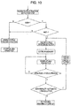
- Fig. 10 is an example of a control flowchart applied to the power conversion devices in Embodiment 1 and Embodiment 2.
- the magnetic pole position is detected each time before initiating a startup from a stop, and the startup is initiated using the magnetic pole position estimation data. If it is "1," "data stored in the memory” is used; therefore, the magnetic pole position is detected before operation of the motor only at the first time, and the magnetic pole position estimation data is stored in the memory, and a startup is initiated using the stored data. Then, an estimation magnetic pole position when the motor is stopped is stored in the memory, it only needs to refer to the magnetic pole position data in the memory at a startup at the second time or later.
- the magnetic pole position is changed due to the rotation of a rotor.
- abnormal current flows through the permanent magnet synchronous motor because the actual magnetic pole position is different from the magnetic pole position estimation, and excess current makes the power conversion device trip (cut off).
- abnormal trip is automatically cancelled, the magnetic pole position is detected again, the magnetic pole position estimation data is stored in the memory, and a startup is initiated again using the stored data.
- the power conversion device has a function to automatically cancel such abnormal trip at a startup of the permanent magnet synchronous motor, it does not let abnormal current flow at a startup of the permanent magnet synchronous motor; therefore, there is an advantage of removing worry about excess current making the power conversion device trip (cut off) and causing careless system down.
- this uses a function to be able to select setting in advance at the digital operation panel, when the permanent magnet synchronous motor is started, from setting of: operating the abnormal trip automatic cancellation function at a startup, and re-estimating the magnetic pole position of the synchronous motor by the estimation means; and disabling the abnormal trip automatic cancellation function, performing abnormal trip display (power conversion device cut-off state) and following determination processing by the user.
- the setting can be also selected in advance from the upper-level device 12 in the same manner.
- the explanation is given of the first function in the case of operating one permanent magnet synchronous motor, but if there are n motors, it only needs to provide a first function to an nth function.
- the embodiments enable an operation panel or an upper-level device to select either driving the permanent magnet synchronous motor using the magnetic pole position estimation data stored in the memory or estimating the magnetic pole position of the permanent magnet synchronous motor by the estimation means for estimating a magnetic pole position at a startup of the permanent magnet synchronous motor; and thereby have large users' merits of being able to provide the power conversion device and the control method for the permanent magnet synchronous motor that are capable of using magnetic pole position estimation data suitable for a load application determined by a system configuration without taking a magnetic pole position estimation time.
Abstract
Description
- The present invention relates to a power conversion device and a control method for a permanent magnet synchronous motor.
- Up to now, when a power conversion device performs variable speed control of a permanent magnet synchronous motor, it has to detect a magnetic pole position at a startup of the permanent magnet synchronous motor. This is because if the magnetic pole position of the permanent magnet synchronous motor is different from the output phase of the power conversion device, the permanent magnet synchronous motor will go out of control due to a pull-out phenomenon specific to permanent magnet synchronous motors.
Patent Literature 1 discloses a magnetic pole detection method that derives a current phase at an absolute scale absolute position at the time of power-on by calculation from relation between the absolute scale absolute position and the current phase stored in a storage device. - Patent Literature 1:
JP-A-2007-116759 - Ordinarily, when a permanent magnet synchronous motor is operated, the magnetic pole position of the permanent magnet synchronous motor is estimated using information on current and voltage of the permanent magnet synchronous motor. However, when the operation of the permanent magnet synchronous motor is stopped, current and voltage become zero and information cannot be obtained, thereby causing information on the magnetic pole position estimated up until that point to be lost; therefore, there is a need for means to estimate the magnetic pole position each time when the permanent magnet synchronous motor is restarted.
- In the case of a permanent magnet synchronous motor equipped with a magnetic pole position sensor, it is always able to detect the magnetic pole position even when a power conversion device is stopped, but in the case of a permanent magnet synchronous motor not equipped with a magnetic pole position sensor, the magnetic pole position is detected each time before initiating a startup from a stop.
- For this reason, paragraph [0008] in
Patent Literature 1 discloses that "in synchronous motor magnetic pole detection methods for determining a current phase to be applied on the basis of a provisional magnetic pole position which is a startup position, provided is a magnetic pole detection method that stores in a storage device an absolute scale absolute position after magnetic pole position estimation and a current phase at that position, as a current phase at an absolute scale absolute position or an absolute scale absolute position at a current phase, and derives a current phase at the absolute scale absolute position at the time of power-on by calculation from relation between the absolute scale absolute position and the current phase stored in the storage device from the time of next power-on." - However, in the invention in
Patent Literature 1, an absolute encoder, which is a magnetic pole position sensor, is indispensable, and it is installed at the side opposite to a load of a synchronous motor. When an encoder is installed at a motor, the encoder must be installed at the side opposite to the load of the motor, and therefore a dual-shaft motor is required; consequently, there arise problems such as securing an installation place due to increase in the size of the motor including the encoder, an erroneous signal due to noise mixed in encoder output, and necessity for a dual shaft-processed special motor. - Generally, in order to detect a magnetic pole position, it requires a time from hundreds milliseconds to several seconds; therefore, detecting the magnetic pole position each time at a startup causes an increased tact time in the case of load applications that frequently repeat a start and a stop, and thus, it is not a desirable estimation mode.
- For example, in the case of a permanent magnet synchronous motor with a mechanical brake, however, the brake is applied without fail at a stop of the motor, and thereby the motor does not rotate through inertia nor is rotated by a load at the stop. Therefore, it is not necessary to detect the magnetic pole position each time before initiating a startup from a stop, and possible to start the permanent magnet synchronous motor from the stop using initial magnetic pole position estimation.
- In other words, depending on a system configuration, it is not necessary to detect the magnetic pole position each time, and there is an application that can be controlled using initial magnetic pole position estimation data. Taking above into consideration, the present invention aims for providing a configuration that enables a user to select means for identifying the magnetic pole position depending on the system configuration.
- In order to achieve the above objective, for example, in the present invention, a power conversion device that comprises a power conversion unit for converting direct current into alternating current and that performs variable speed control of a synchronous motor in which a permanent magnet is used has a configuration that comprises: a current detection circuit for detecting current flowing through the synchronous motor; estimation means for estimating a magnetic pole position of the synchronous motor at a startup of the synchronous motor; and a memory for storing magnetic pole position estimation data indicating a magnetic pole position at a stop of the synchronous motor, and that comprises: selection means for selecting magnetic pole position estimation data stored in the memory or magnetic pole position estimation data obtained by the estimation means; and a control unit for driving the synchronous motor using the magnetic pole position estimation data selected by the selection means.
- The present invention enables reduction in a magnetic pole position estimation time by using different magnetic pole position estimation data depending on a system.
-
- [
Fig. 1] Fig. 1 is an example of a configuration diagram of a power conversion device according to an embodiment. - [
Fig. 2] Fig. 2 is an example of another configuration diagram of the power conversion device according to the embodiment. - [
Fig. 3] Fig. 3 is a simple equivalent circuit of a permanent magnet synchronous motor. - [
Fig. 4] Fig. 4 is a control block diagram of the power conversion device according to the embodiment. - [
Fig. 5] Fig. 5 is a display example of a digital operation panel according to the embodiment. - [
Fig. 6] Fig. 6 is a control block diagram of the power conversion device according to the embodiment. - [
Fig. 7] Fig. 7 is a display example of the digital operation panel according to the embodiment. - [
Fig. 8] Fig. 8 is a configuration diagram of a power conversion device according to an embodiment. - [
Fig. 9] Fig. 9 is a display example of a digital operation panel according to the embodiment. - [
Fig. 10] Fig. 10 is an example of a control flowchart according to the embodiments. - [
Fig. 11] Fig. 11 is an explanatory diagram of magnetic pole position detection according to the embodiment. - Hereinafter,
Embodiment 1 will be explained with reference to the drawings. Constituents common to figures are given the same reference numerals. In addition,Embodiment 1 is not limited to shown examples. The form of a power conversion device inEmbodiment 1 will be explained below reference to the figures.Fig. 1 is an example of a configuration diagram of the power conversion device according toEmbodiment 1. - A
power conversion device 10 inFig. 1 comprises aforward converter 1 for supplying power to a PM motor (hereinafter called a permanent magnet synchronous motor) directly coupled onto aload device 11, asmoothing capacitor 2, an inverse converter 3, a controlarithmetic device 4, acontrol circuit 5, acooling fan 6, adigital operation panel 7, adrive circuit 8, and avoltage detection circuit 9.Fig. 1 shows the case of using an AC power supply as any input power supply. Theforward converter 1 converts AC power to DC power. Thesmoothing capacitor 2 is comprised in a DC intermediate circuit. - The inverse converter 3 converts DC power into AC power with any frequency. Inside the inverse converter 3, as a typical switching element, for example, an IGBT is mounted. The switching element is not limited to an IGBT, and any thing is sufficient as long as it has a form as a switching element. For example, it may be SiC (Silicon Carbide) or GaN (Gallium Nitride), which is a wide-band gap semiconductor element having performance overleaping the solid-state property value limit of Silicon (Si).
- The
cooling fan 6 takes the heat from power modules in theforward converter 1 and the inverse converter 3. Thedigital operation panel 7 performs setting and changing of various control data of the power conversion device and displaying of an abnormal state and a monitor state. Theoperation panel 7 is provided with a display unit capable of abnormality display, and abnormality is displayed on the display unit when the abnormality in the power conversion device is detected. Theoperation panel 7 in the embodiment is not limited to a particular type, but taking operability for a device user into consideration, as a digital operation panel, it has a configuration such that the user can operate it while looking at the display on the display unit. - The display unit does not necessarily need to have an integral structure with the
operation panel 7, but it is desirable to have the integral structure so as to enable an operator of theoperation panel 7 to operate it while looking at the display. Various control data of the power conversion device input from theoperation panel 7 is stored in an unshown storage unit. - The
control circuit 5 controls a switching element of the inverse converter 3 on the basis of various control data input by thedigital operation panel 7, and serves to manage control of the wholepower conversion device 10. Thecontrol circuit 5 is equipped with the control arithmetic device 4 (for example, a microcomputer) and configured to be able to perform control processing necessary according to various control data input by thedigital operation panel 7. In addition, it is also configured to be able to perform control processing necessary according to various control data input from an upper-level device 12 (for example, a communication device or radio device). Although an internal configuration is omitted, the control arithmetic device 4 (for example, a microcomputer) performs arithmetic on the basis of information from storage data in the storage unit storing various control data. - Current detectors CTs detect line current of the U phase and W phase of the permanent magnet synchronous motor. Line current of the V phase is obtained as iv = -(iu+iw) from an AC condition (iu+iv+iw = 0).
-
Fig. 1 shows an example of using two CTs, but three CTs may be used and line current of each of the U phase, V phase and W phase may be detected. - The
drive circuit 8 drives the switching element of the inverse converter 3 on the basis of a command from thecontrol circuit 5. Inside thedrive circuit 8, a switching regulator circuit (DC/DC converter) is mounted, generates various DC voltage necessary to operate the power conversion device, and supplies it to various constituents. The DCvoltage detection circuit 9 detects voltage of the smoothingcapacitor 2 forming the DC intermediate circuit. In addition, in the case of supplying DC power instead of AC power as any input power, it is only necessary to connect the "+" side of a DC power supply to a DC terminal P side, and to connect the "-" side of the DC power supply to a DC terminal N side. Furthermore, it may be good to connect AC terminals R, S and T together, to connect the "+" side of the DC power supply to this connection point, and to connect the "-" side of the DC power supply to the DC terminal N side. Conversely, it may be good to connect the "+" side of the DC power supply to the DC terminal P side, to connect the AC terminals R, S and T together, and to connect the "-" side of the DC power supply to this connection point. -
Fig. 2 is an example of another configuration diagram. In the same way as the configuration example inFig. 1 , it is able to perform below-described control. Constituents common to and the same functions asFig. 1 are given the same reference numerals. Difference fromFig. 1 is the detection positions of current detectors. - SH1, SHi and SHd are shunt resistors for current detection, SH1 detects current at the N side of the DC intermediate circuit, SHi is connected with IGBTs of the U phase, V phase and W phase, which are switching elements of a lower arm constituting part of the inverse converter 3, and SHd is connected with diodes connected in parallel with the respective IGBTs which are switching elements.
- In other words, the shunt resistor SHi provided at a DC bus bar side of the power conversion device is a current detector for detecting composite current flowing through the IGBTs, and the shunt resistor SHd provided at the DC bus bar side of the power conversion device is a current detector for detecting composite current flowing through the diodes connected in parallel with the respective IGBTs. The shunt resistors provided at the DC bus bar side of the power conversion device are able to detect current flowing through the permanent magnet synchronous motor.
- The shunt resistors SHi and SHd are connected with the IGBT and the diode, respectively, in the lower arm constituting part of the U phase, but they may be connected with an IGBT and a diode, respectively, in an upper arm constituting part of the U phase to detect current. In addition,
Fig. 3 is a simple equivalent circuit of the permanent magnet synchronous motor driven by the power conversion device in the embodiment. It consists of armature resistance Ra, armature inductance La, armature current Ia, speed electromotive force Ea, and magnetic flux of a permanent magnet Φm. -
Fig. 4 is a control block diagram of the power conversion device according to the embodiment. This shows a control block that is inside thecontrol circuit 5 disclosed inFigs. 1 and2 , and that is a partial processing block performed by the control arithmetic device 4 (for example, a microcomputer). - As control for the power conversion device to drive the permanent magnet synchronous motor, supposing that a "d" axis is the direction of magnetic flux Φm generated by the attached magnet, the power conversion device controls the vector of current so that the armature current Ia flows through a "q" axis (electrically θ = 90°) orthogonal to the "d" axis. In order to set the "d" axis, the direction of magnetic flux generated by the magnet is estimated by a magnetic pole position estimation circuit without using a magnetic pole position sensor.
- Generation torque is represented by vector product of magnetic flux and current regardless of a DC machine or an AC machine (T = Φm*I*sinθ). In this case, because an electric angle between the magnetic flux Φm and the armature current Ia is controlled to θ = 90°, the generation torque becomes T = Φm*Ia*sin90° = Φm*Ia. In this case, the armature current Ia corresponds to a torque current component Iq.
- The current detectors CTs detect the line current of the permanent magnet synchronous motor, a dq-axis conversion unit converts the detected current into current in orthogonal "d" and "q" axes, and the resulting current is decomposed into an excitation current component Id and a torque current component Iq.
- If a weak field control or the like is not conducted, a d-axis current command flowing in the direction of the magnetic flux Φm is set to Id* = 0, and a circuit for d-axis current control operates so that the detected excitation current component Id is always 0. Controlled in this manner, the armature current Ia flowing through the permanent magnet synchronous motor is controlled as a torque current component Iq by operation of a q-axis current control system. In other words, the armature current Ia flowing through the permanent magnet synchronous motor can be operated as a torque current component proportional to the generation torque of the motor.
- In a weak field region, the d-axis current command is set to Id*<0, and the magnetic flux Φm generated by the attached magnet is reduced (Φd = Φm-k*Id). In order to reduce the magnetic flux Φm, the phase of the armature current Ia flowing through the permanent magnet synchronous motor should be controlled to 90° or more (θ>90°).
- Generally, because a time required to detect the magnetic pole position is from hundreds milliseconds to several seconds, detecting the magnetic pole position each time at a startup causes an increased tact time in the case of load applications that frequently repeat a start and a stop, and is not a desirable estimation mode.
- For example, in the case of a permanent magnet synchronous motor with a mechanical brake, however, the motor does not rotate through inertia nor is rotated by a load after a stop because the brake is applied without fail when the motor is stopped; therefore, the magnetic pole position detected through estimation is not changed. Consequently, it is not necessary to detect the magnetic pole position each time before initiating a startup from a stop state, and it is possible to start the permanent magnet synchronous motor using magnetic pole position estimation data at the time point of a stop after initiating the startup.
- In other words, depending on a system configuration, it is not necessary to detect the magnetic pole position each time, and there is an application that can be controlled using magnetic pole position estimation data at the time point of a stop after initiating a startup.
- In the case of such an application, it is solvable by storing the magnetic pole position estimation data at the time point of a stop after initiating a startup in a memory.
- As a matter of course, in the case where power supply to the power conversion device is not cut off, the magnetic pole position estimation data is simply stored in the memory (for example, a RAM), but in the case where power supply is cut off, if the data is only stored in the memory, the estimated information on the magnetic pole position will be lost when power supply is cut off. Consequently, the magnetic pole position at the time of a stop after initiating a startup is stored in a nonvolatile memory each time when power supply is cut off. Such a configuration allows the permanent magnet synchronous motor to be started using the information on the magnetic pole position stored in the nonvolatile memory when power is turned on.
- Storing the data in the memory is processed by the control arithmetic circuit device 4 (for example, a microcomputer) according to a command from the
digital operation panel 7 or the upper-level device 12. -
Fig. 11 is an explanatory diagram of magnetic pole position detection according to the embodiment. (c) shows an explanatory diagram of what the detected magnetic pole position is a position on the basis of. An angle δ of a magnetic pole position detected on the basis of the U phase of an armature winding of a three-phase permanent magnet synchronous motor is determined. - The angle δ of the magnetic pole position is set as the "d" axis on control, and a right angle direction to the "d" axis is set as the "q" axis on control. For example, if weak field control or the like is not conducted, the armature current Ia is controlled so as to only flow through the "q" axis on control. In other words, the detected magnetic pole position is the angle δ (direction of the magnetic flux Φm) on the basis of the U phase of the armature winding, and the angle δ of the magnetic pole position (magnetic pole position estimation data) is stored in the memory. In the embodiment, the explanation is given on the basis of the U phase of the armature winding, but the basis may be the V phase or the W phase. In addition, an imaginary reference axis may be set, and the angle δ of the magnetic pole position detected on the basis of that axis may be determined.
- Naturally, the control arithmetic device 4 (for example, a microcomputer) inside the power conversion device detects the magnetic pole position of the synchronous motor, and controls the synchronous motor according to the detected value; therefore, it always recognizes the magnetic pole position of the synchronous motor. In other words, the control
arithmetic device 4 always recognizes which angle δ the magnetic pole position is while the synchronous motor is rotating controlled by the power conversion device. Consequently, the controlarithmetic device 4 also recognizes the angle δ of the magnetic pole position at the time point when the synchronous motor is stopped. - If the synchronous motor rotates through inertia when it is stopped once, or it is rotated by wind through a fan or the like after a stop, however, there arises difference between the magnetic pole position recognized by the control
arithmetic device 4 and an actual magnetic pole position (change in the magnetic pole position by rotation after the stop). Consequently, the controlarithmetic device 4 cannot get hold of the actual magnetic pole position of the synchronous motor. - The explanation is given of making the angle δ into the magnetic pole position on the basis of the U phase, but there are many methods for detecting the magnetic pole position (direction of the magnetic flux Φm). Therefore, the example is only one example, and does not limit determination methods for the magnetic pole position (direction of the magnetic flux Φm) or the angle δ of the magnetic pole position. In fact, the angle δ of the magnetic pole position may be not an actual angle as long as it can define the position of the magnetic pole.
-
- (a) shows an example indicating the magnetic pole position in the case where a mechanical brake or the like is not installed relative to a startup and stop operation pattern of the synchronous motor. In the case where there is no mechanical brake or the like, the motor is started by the power conversion device and when it is stopped once, it rotates through inertia, or it is rotated by wind after the stop if it is equipped with a fan or the like; therefore, a magnetic pole position (direction of the magnetic flux Φm) ΦmA at the stop is actually moved to Φma, and the actual magnetic pole position(direction of the magnetic flux Φm) Φma is situated at a position different from the magnetic pole position (direction of the magnetic flux Φm) ΦmA recognized by the power conversion device, thereby causing the motor to go out of control.
- Whenever the motor stops, there arises large difference between magnetic pole positions (direction of the magnetic flux Φm) ΦmA, ΦmB, ΦmC, ΦmD, ΦmE recognized by the power conversion device and actual magnetic pole positions (direction of the magnetic flux Φm) Φma, Φmb, Φmc, Φmd, Φme at respective time points. The magnetic pole positions recognized by the power conversion device are different from the actual magnetic pole positions, which causes an impossible state of controlling the synchronous motor. For this reason, in such a system that depends on a load, the magnetic pole position must be correctly detected each time before initiating a startup from the stop state, and it is necessary to control the motor according to the detected actual magnetic pole position. Here, a magnetic pole position (direction of the magnetic flux Φm) Φm0 is a first magnetic pole position (initial magnetic pole position) detected at a first startup.
- Even if there is no mechanical brake or the like, when the motor is started by the power conversion device and then stopped once, if it does not rotate through inertia nor is rotated by wind through a fan or the like after the stop, there is no need to detect the magnetic pole position each time; therefore, the motor does not go out of control as long as the magnetic pole position is stored in the memory and it is started using the data in the memory.
-
- (b) shows an example indicating the magnetic pole position in the case where a mechanical brake or the like is installed relative to a startup and stop operation pattern of the synchronous motor. In the case where there is a mechanical brake, when the motor is started by the power conversion device and then stopped once, it does not rotate through inertia nor is rotated by wind through a fan or the like after the stop; therefore, the magnetic pole position (direction of the magnetic flux Φm) ΦmA when it is stopped always accords with the actual magnetic pole position (direction of the magnetic flux Φm) Φma. In this case, there is no need to correctly detect the magnetic pole position each time before initiating a startup from the stop state, and the motor does not go out of control as long as an angle δA of the magnetic pole position (direction of the magnetic flux Φm) ΦmA at a motor stop A is stored in the memory and it is started using the data.
- In other words, angles of the magnetic pole positions at a motor stop 0 (initial magnetic pole position), motor stop B, motor stop C, motor stop D, motor stop E, i.e. an angle δ0 for the time point of motor stop 0, an angle δB for the time point of motor stop B, an angle δC for the time point of motor stop C, an angle δD for the time point of motor stop D, and an angle δE for the time point of motor stop E are stored in the memory, and when the motor is started from the respective time points of stop, as long as it is started using the corresponding magnetic pole position estimation data stored in the memory, the motor does not go out of control. In other words, it means that what is used is the magnetic pole position estimation data δ0 when it is started from the time point of motor stop 0, the magnetic pole position estimation data δA when it is started from the time point of motor stop A, the magnetic pole position estimation data δB when it is started from the time point of motor stop B, the magnetic pole position estimation data δC when it is started from the time point of motor stop C, the magnetic pole position estimation data δD when it is started from the time point of motor stop D, and the magnetic pole position estimation data δE when it is started from the time point of motor stop E.
- The motor stop 0, motor stop A, motor stop B, motor stop C, motor stop D, and motor stop E may be considered as time points when output of the power conversion device is stopped.
- Depending on a system configuration, there is a case where the stop position is always fixed. In this case, because the motor always stops at the same position, it is also possible to store the angle δ0 of the magnetic pole position (direction of the magnetic flux Φm) Φm0 at the time point of motor stop 0 (initial magnetic pole position) in the memory, and starts the motor using the magnetic pole position estimation data. As a matter of course, in the case of such a system, the angle of a magnetic pole position stored in the memory may be δA or δB or δC or δD or δE.
- The magnetic pole position estimation data stored in the memory is not limited to the first magnetic pole position (initial magnetic pole position) estimation data. According to a system configuration, the user may decide which state the magnetic pole position estimation data detected at is stored in the memory, and the magnetic pole position estimation data to be stored is not limited to the magnetic pole position (initial magnetic pole position) data detected at the first startup when the system is driven.
- As described above, being able to select the motor is started either by detecting the magnetic pole position each time before initiating a startup from the stop state or by using the magnetic pole position estimation data stored in the memory depending on a system can contribute to optimization of the tact time of the system and improve the freedom of choice in the system configuration; therefore, users' merits are extremely large.
- According to the above, a determination processing unit performs determination processing of whether the power conversion device detects a magnetic pole estimation position at the time point of a stop after initiating a startup, stores the magnetic pole position estimation data in the memory, and starts the motor using the estimation data stored in the memory after that or performs magnetic pole position detection each time at a startup, and starts the motor using the magnetic pole position estimation data. In other words, in the case of starting the motor using "the data stored in the memory," the determination processing unit operates so as to make the data valid (adopting as data) in the memory storing the magnetic pole position estimation data detected by the magnetic pole position estimation circuit at the time point of the stop after initiating the startup, and so as not to select the data (not adopting as data) detected by the magnetic pole position estimation circuit. In the case of starting the motor using "the data estimated at a startup each time," the determination processing unit operates so as to make the magnetic pole position estimation data detected by the magnetic pole position estimation circuit each time at a startup valid (adopting as data), and so as not to select the data stored in the memory (not adopting as data).
- As a matter of course, in the case where power supply to the power conversion device is not cut off, the magnetic pole position estimation data is simply stored in the memory (for example, a RAM), and in the case where power supply is cut off, the magnetic pole position estimation data at the time point of the stop after initiating the startup may be stored in a nonvolatile memory each time when power supply is cut off.
-
Fig. 6 is another control block diagram of the power conversion device according to the embodiment. Constituents common to and the same functions asFig. 4 are given the same reference numerals. Difference fromFig. 4 is in thatFig. 6 has a configuration of storing the magnetic pole position detection data in a flash memory inside a microcomputer as the memory. It is also possible to perform the same control asFig. 4 in the configuration inFig. 6 . -
Fig. 5 is a display example of a digital operation panel according to the embodiment. The display example consists essentially of a display code, a function name, a monitor or data range, and initial data. When "A060" is selected from display codes by the digital operation panel, the function name is a "magnetic pole position estimation data storing selection" field, and an operator can select setting at will such that if the operator selects "1" from "monitor or data range," "store in the memory" is set, and if the operator selects "2," "do not store in the memory" is set. In addition, "initial data" is a default value when the power conversion device was shipped. Obviously, "A060" can be selected from the upper-level device 12 in the same manner. - "Store in the memory" means, for example, in the case of a system configuration of driving a permanent magnet synchronous motor with a mechanical brake, to detect an initial magnetic pole position and after that to store a magnetic pole position at the time point of a stop after initiating a startup in the memory each time. It means to start the motor each time using the estimation data stored in the memory per stop, and not to perform magnetic pole position detection each time at a startup.
- As a matter of course, depending on a system configuration, there is a case where the stop position is always fixed. In this case, because a motor always stops at the same position, it is also possible to store the angle δA of the magnetic pole position (direction of the magnetic flux Φm) ΦmA at the motor stop A in the memory, and to start the motor using the magnetic pole position estimation data. In the case of such a system, the angle of a magnetic pole position stored in the memory may be δ0 or δB or δC or δD or δE, and there is no chance of going out of control as long as starting the motor using that data.
- So that the user is able to check the magnetic pole position estimation data with eyes, the display unit provided at the
digital operation panel 7 or the upper-level device 12 displays the magnetic pole position estimation data read out from the memory. In addition, "do not store in the memory" means to detect the magnetic pole position by the magnetic pole position estimation circuit each time at a startup, and to start the motor using the magnetic pole position estimation data. -
Fig. 7 is another display example of the digital operation panel. The display example consists essentially of a display code, a function name, a monitor or data range, and initial data. When "A060" is selected from lots of prepared display codes by the digital operation panel, the function name is a "magnetic pole position estimation data storing selection" field, and an operator can select use at will such that if the operator selects "1" from "monitor or data range," "store in the memory" is used, and if the operator selects "2," "do not store in the memory" is used. In addition, "initial data" is a default value when the power conversion device was shipped. - When "A061" is selected from the prepared display codes by the digital operation panel, the function name is a "magnetic pole position estimation data selection" field, and the operator can select use at will such that if the operator selects "1" from "monitor or data range," "data stored in the memory" is used, and if the operator selects "2," "data estimated at a startup each time" is used. In addition, "initial data" is a default value when the power conversion device was shipped.
- Obviously, "A060" and "A061" can be also selected from the upper-
level device 12 in the same manner. In other words, depending on the system configuration at the user, the user can select, as the magnetic pole position detection data, either using the initial magnetic pole position detection data stored in the memory or using the magnetic pole position estimation data detected by the magnetic pole position estimation circuit each time at a startup. -
Fig. 8 is a configuration diagram of a power conversion device according toEmbodiment 2. Constituents common to and the same functions asFig. 1 inEmbodiment 1 are given the same reference numerals. It is a system configuration in which a PM motor 1 (hereinafter called a permanent magnet synchronous motor 1) is equipped with a mechanical brake BR, and a PM motor 2 (hereinafter called a permanent magnet synchronous motor 2) is not equipped with a mechanical brake BR. The permanentmagnet synchronous motor 1 and the permanentmagnet synchronous motor 2 may be the same model of motors, and may be motors with different capacity from each other. In a matter of course, there is no limitation on the number of motors. - Electromagnetic contactors MC1 and MC2 are mechanically and electrically interlocked and are designed so as not to be on at the same time. When the MC1 is in an on state, the MC2 is in an off state without fail.
- This is a case where one
power conversion device 10 selectively drives any one of the two permanent magnet synchronous motors. "Sig" is a signal to select any one of the two permanent magnet synchronous motors. In addition, "Brs" is an on-or-off signal from the power conversion device to the mechanical break BR, and when the power conversion device stops output, it outputs an on signal to the mechanical break BR to operate the break. Obviously, on-and-off control of the mechanical break BR may be performed from the outside other than the power conversion device. - In the case of this system configuration, because the permanent
magnet synchronous motor 1 puts on the brake without fail when the motor stops, the motor does not rotate through inertia nor is rotated by a load at the stop; therefore, the power conversion device does not need to detect the magnetic pole position each time before initiating a startup from a stop, and is able to start the permanent magnet synchronous motor from the stop using the initial magnetic pole position estimation data detected at the first time and stored in the (nonvolatile) memory. - On the other hand, because the permanent
magnet synchronous motor 2 is not equipped with a brake, the power conversion device is able to start the permanent magnet synchronous motor from a stop using the magnetic pole position estimation data detected by the magnetic pole position estimation circuit each time before initiating a startup from a stop. - For example, if the "Sig" signal is "High," the permanent
magnet synchronous motor 1 is selected, and it is possible to start it using the initial magnetic pole position estimation data stored in the (nonvolatile) memory. If the "Sig" signal is "Low," the permanentmagnet synchronous motor 2 is selected, and it is possible to detect the magnetic pole position each time at a startup, and to start it using the detected data. - In addition, "SW" is a hardware switch for selecting either driving the permanent magnet synchronous motors using the magnetic pole position estimation data stored in the memory or starting the permanent magnet synchronous motor using the magnetic pole position estimation data detected by the magnetic pole position estimation circuit each time at a startup of the permanent magnet synchronous motor. In the case of a configuration in which the
digital operation panel 7 is installed remotely, if the power conversion device is provided with the hardware switch SW, the user is able to enjoy an advantage of being able to simply select either one of the two permanent magnet synchronous motors by the hardware switch SW on the power conversion device without using thedigital operation panel 7 installed remotely. - In the embodiment, in the case of the permanent
magnet synchronous motor 2 not equipped with a brake, although the explanation is given of starting the permanent magnet synchronous motor using the magnetic pole position estimation data detected by the magnetic pole position estimation circuit each time at a startup, it is not intended to limit presence or absence of a brake. In other words, if it is not a system in which a motor rotates through inertia due to external force or the like, or is rotated by a load at a stop, it is not necessary to detect the magnetic pole position by the magnetic pole position estimation circuit each time at a startup, and the motor can be started using the magnetic pole position estimation data stored in the memory. - Consequently, the freedom of selection can be increased if the user is enabled to select either starting the motor using magnetic pole position estimation data stored in the (volatile) memory or detecting magnetic pole position estimation data by the magnetic pole position estimation circuit each time at a startup, depending on the system configuration.
-
Fig. 9 is a display example of a digital operation panel according toEmbodiment 2. The display example is a selection display example at the digital operation panel of the magnetic pole position estimation data of the permanentmagnet synchronous motor 1 and the permanentmagnet synchronous motor 2 in the system configuration shown inFig. 8 , and is configured by a software switch. - In the same manner as before, the display example consists essentially of a display code, a function name, a monitor or data range, and initial data. The display codes "A060" and "A061" show a selection field of the magnetic pole position estimation data of the permanent
magnet synchronous motor 1 as a first function, and display codes "A160" and "A161" show a selection field of the magnetic pole position estimation data of the permanentmagnet synchronous motor 2 as a second function. In the example, because "A060" and "A061" corresponding to the first function both have "1," the permanentmagnet synchronous motor 1 is driven using the initial magnetic pole position estimation data stored in the (volatile) memory, and because "A160" and "A161" corresponding to the second function both have "2," the permanentmagnet synchronous motor 2 is driven using the magnetic pole position estimation data detected by the magnetic pole position estimation circuit each time at a startup. - In other words, by providing the first function and the second function like this, and making them selectable from the digital operation panel, one power conversion device is enabled to operate the two permanent magnet synchronous motors in different modes (magnetic pole position estimation data stored in the memory or magnetic pole position estimation data detected by the magnetic pole position estimation circuit each time).
- In the embodiment, the explanation is given using an example of two permanent magnet synchronous motors, but it is not intended to limit the number of driven motors. In the case of n motors, it only requires to provide a first function to an nth function.
Fig. 10 is an example of a control flowchart applied to the power conversion devices inEmbodiment 1 andEmbodiment 2. - Before operating a permanent magnet synchronous motor, confirmation is made to check whether the display code "A060" is "1," and if it is not "1," which is setting "not to store the magnetic pole position estimation data in the memory;" therefore, a startup is initiated using the magnetic pole position estimation data detected by the magnetic pole position estimation circuit each time before initiating a startup from a stop.
- On the other hand, if the display code "A060" is "1," confirmation is made to check whether the display code "A061" is "1," and if it is not "1," which is setting to use "data estimated at a startup each time;" therefore, the magnetic pole position is detected each time before initiating a startup from a stop, and the startup is initiated using the magnetic pole position estimation data. If it is "1," "data stored in the memory" is used; therefore, the magnetic pole position is detected before operation of the motor only at the first time, and the magnetic pole position estimation data is stored in the memory, and a startup is initiated using the stored data. Then, an estimation magnetic pole position when the motor is stopped is stored in the memory, it only needs to refer to the magnetic pole position data in the memory at a startup at the second time or later.
- For example, in the case where maintenance of the brake is performed in maintenance, however, the magnetic pole position is changed due to the rotation of a rotor. In this state, if the motor is started using the magnetic pole position estimation data stored in the memory, abnormal current flows through the permanent magnet synchronous motor because the actual magnetic pole position is different from the magnetic pole position estimation, and excess current makes the power conversion device trip (cut off). In this case, abnormal trip is automatically cancelled, the magnetic pole position is detected again, the magnetic pole position estimation data is stored in the memory, and a startup is initiated again using the stored data.
- If the power conversion device has a function to automatically cancel such abnormal trip at a startup of the permanent magnet synchronous motor, it does not let abnormal current flow at a startup of the permanent magnet synchronous motor; therefore, there is an advantage of removing worry about excess current making the power conversion device trip (cut off) and causing careless system down.
- As a matter of course, this uses a function to be able to select setting in advance at the digital operation panel, when the permanent magnet synchronous motor is started, from setting of: operating the abnormal trip automatic cancellation function at a startup, and re-estimating the magnetic pole position of the synchronous motor by the estimation means; and disabling the abnormal trip automatic cancellation function, performing abnormal trip display (power conversion device cut-off state) and following determination processing by the user. Obviously, the setting can be also selected in advance from the upper-
level device 12 in the same manner. - In the embodiment, the explanation is given of the first function in the case of operating one permanent magnet synchronous motor, but if there are n motors, it only needs to provide a first function to an nth function.
- As is indicated by the above embodiments, the embodiments enable an operation panel or an upper-level device to select either driving the permanent magnet synchronous motor using the magnetic pole position estimation data stored in the memory or estimating the magnetic pole position of the permanent magnet synchronous motor by the estimation means for estimating a magnetic pole position at a startup of the permanent magnet synchronous motor; and thereby have large users' merits of being able to provide the power conversion device and the control method for the permanent magnet synchronous motor that are capable of using magnetic pole position estimation data suitable for a load application determined by a system configuration without taking a magnetic pole position estimation time.
-
- 1
- Forward converter
- 2
- Smoothing capacitor
- 3
- Inverse converter
- 4
- Control arithmetic device
- 5
- Control circuit
- 6
- Cooling fan
- 7
- Digital operation panel
- 8
- Drive circuit
- 9
- Voltage detection circuit
- 10
- Power conversion device
- 11
- Load device
- CT
- Current detector
- SH1, SHi, SHd
- Shunt resistor for current detection at DC bus bar side
- BR
- Mechanical brake
- Sig
- Synchronous motor selection signal
- Brs
- Brake BR on-or-off signal
- PM motor
- Permanent magnet synchronous motor
- MC1, MC2
- Electromagnetic contactor
- SW
- Hardware switch
Claims (15)
- A power conversion device that comprises a power conversion unit for converting direct current into alternating current and that performs variable speed control of a synchronous motor in which a permanent magnet is used, comprising:a current detection circuit for detecting current flowing through the synchronous motor;estimation means for estimating a magnetic pole position of the synchronous motor at a startup of the synchronous motor; anda memory for storing magnetic pole position estimation data indicating a magnetic pole position at a stop of the synchronous motor,wherein the power conversion device further comprises selection means for selecting either magnetic pole position estimation data stored in the memory or magnetic pole position estimation data obtained by the estimation means, and a control unit for driving the synchronous motor using the magnetic pole position estimation data selected by the selection means.
- The power conversion device according to Claim 1,
wherein:the memory is a nonvolatile memory, andwhen power supply to the power conversion device is cut off, the magnetic pole position estimation data at a stop of the synchronous motor is stored in the volatile memory. - The power conversion device according to any of Claims 1 and 2, wherein
when abnormality occurs at a startup of the synchronous motor, the control unit performs any of abnormal trip automatic cancelling to re-estimate the magnetic pole position of the synchronous motor by the estimation means or abnormal trip display and shift of the power conversion device into a cut-off state. - The power conversion device according to Claim 1, comprising
an operation panel for setting an operation condition of the power conversion device, wherein
the operation panel enables selection of either driving the synchronous motor using the magnetic pole position estimation data stored in the memory or driving the synchronous motor by estimating the magnetic pole position of the synchronous motor by the estimation means for estimating a magnetic pole position at a startup of the synchronous motor. - The power conversion device according to Claim 1, comprising
an upper-level device for setting an operation condition of the power conversion device, wherein
the upper-level device enables selection of either driving the synchronous motor using the magnetic pole position estimation data stored in the memory or driving the synchronous motor by estimating the magnetic pole position of the synchronous motor by the estimation means for estimating a magnetic pole position at a startup of the synchronous motor. - The power conversion device according to Claim 1, comprising
a hardware switch for selecting either driving the synchronous motor using the magnetic pole position estimation data stored in the memory or driving the synchronous motor by estimating the magnetic pole position of the synchronous motor by the estimation means for estimating a magnetic pole position at a startup of the synchronous motor. - The power conversion device according to Claim 3, wherein
when abnormality occurs at a startup of the synchronous motor, the operation panel enables selection of either performing abnormal trip automatic cancelling to re-estimate the magnetic pole position of the synchronous motor by the estimation means or performing abnormal trip display and shifting the power conversion device into a cut-off state. - The power conversion device according to Claim 3, comprising
an upper-level device for setting an operation condition of the power conversion device, wherein
when abnormality occurs at a startup of the synchronous motor, the upper-level device enables selection of either performing abnormal trip automatic cancelling to re-estimate the magnetic pole position of the synchronous motor by the estimation means or performing abnormal trip display and shifting the power conversion device into a cut-off state. - The power conversion device according to Claim 1, comprising
a display unit for displaying the magnetic pole position estimation data read out from the memory. - The power conversion device according to Claim 9, wherein
the display unit is provided at the operation panel or the upper-level device. - A control method for performing variable speed control of a synchronous motor in which a permanent magnet is used, comprising:a step of converting direct current into alternating current;a current detection step of detecting current flowing through the synchronous motor;an estimation step of estimating a magnetic pole position of the synchronous motor at a startup of the synchronous motor;a step of storing magnetic pole position estimation data at a stop of the synchronous motor in a memory; anda control step of driving the synchronous motor according to selection of either driving the synchronous motor using the magnetic pole position estimation data stored in the memory or driving the synchronous motor using the magnetic pole position of the synchronous motor estimated by the estimation means.
- The control method for a permanent magnet synchronous motor according to Claim 11, wherein
when power supply to a device for performing variable speed control of the synchronous motor is cut off, the magnetic pole position estimation data at a stop of the synchronous motor is stored in a volatile memory. - The control method for a permanent magnet synchronous motor according to any of Claims 11 and 12, wherein
when abnormality occurs at a startup of the permanent magnet synchronous motor, control is performed by selecting either operating an abnormal trip automatic cancelling function and re-estimating the magnetic pole position of the synchronous motor by the estimation means or disabling the abnormal trip automatic cancelling function and performing abnormal trip display. - The control method for a permanent magnet synchronous motor according to Claim 11, wherein
if the synchronous motor is provided with a mechanical brake, control is performed so as to drive the synchronous motor using the magnetic pole position estimation data stored in the memory. - The control method for a permanent magnet synchronous motor according to Claim 11, wherein
if the synchronous motor rotates through inertia or by a load after a stop, control is performed so as to drive the synchronous motor using the magnetic pole position of the synchronous motor estimated by the estimation means.
Applications Claiming Priority (1)
| Application Number | Priority Date | Filing Date | Title |
|---|---|---|---|
| PCT/JP2013/081463 WO2015075806A1 (en) | 2013-11-22 | 2013-11-22 | Power conversion device and control method for permanent magnet synchronous motor |
Publications (3)
| Publication Number | Publication Date |
|---|---|
| EP3073629A1 true EP3073629A1 (en) | 2016-09-28 |
| EP3073629A4 EP3073629A4 (en) | 2017-08-16 |
| EP3073629B1 EP3073629B1 (en) | 2023-08-02 |
Family
ID=53179112
Family Applications (1)
| Application Number | Title | Priority Date | Filing Date |
|---|---|---|---|
| EP13897884.6A Active EP3073629B1 (en) | 2013-11-22 | 2013-11-22 | Power conversion device and control method for permanent magnet synchronous motor |
Country Status (4)
| Country | Link |
|---|---|
| EP (1) | EP3073629B1 (en) |
| JP (1) | JP6165877B2 (en) |
| CN (1) | CN105518988B (en) |
| WO (1) | WO2015075806A1 (en) |
Families Citing this family (5)
| Publication number | Priority date | Publication date | Assignee | Title |
|---|---|---|---|---|
| CN108604854B (en) * | 2016-06-22 | 2020-07-24 | 株式会社日立产机系统 | Power conversion device |
| KR101852754B1 (en) * | 2016-10-27 | 2018-04-27 | 엘에스산전 주식회사 | Sensoelss control system for permanent magnet synchronous machine |
| DE112017008092A5 (en) * | 2017-09-25 | 2020-07-09 | Siemens Aktiengesellschaft | Braking method for an electric motor |
| CN109450297B (en) * | 2018-12-19 | 2020-07-03 | 四川虹美智能科技有限公司 | Method and device for controlling motor |
| JP7169218B2 (en) * | 2019-02-12 | 2022-11-10 | 日立Astemo株式会社 | Actuator controller |
Family Cites Families (8)
| Publication number | Priority date | Publication date | Assignee | Title |
|---|---|---|---|---|
| JPH0787784A (en) * | 1993-06-29 | 1995-03-31 | Fujitsu General Ltd | Method and device for controlling brushless motor |
| JP4111599B2 (en) * | 1998-08-28 | 2008-07-02 | 株式会社日立製作所 | Control device for permanent magnet synchronous motor |
| JP2002281795A (en) * | 2001-03-23 | 2002-09-27 | Sumitomo Heavy Ind Ltd | Controlling method for power refeeding to synchronous motor and controller for synchronous motor |
| EP1604450A1 (en) * | 2003-03-03 | 2005-12-14 | Abb Ab | Device and method to configure same |
| KR100657489B1 (en) * | 2005-03-08 | 2006-12-19 | 엘지전자 주식회사 | The method of checking the running state in sensorless motor and apparatus for the same |
| JP4876525B2 (en) | 2005-10-18 | 2012-02-15 | パナソニック株式会社 | Magnetic pole detection method for synchronous motor |
| JP2007174721A (en) * | 2005-12-19 | 2007-07-05 | Mitsubishi Heavy Ind Ltd | Apparatus and method for detecting initial rotational position in brushless dc motor |
| JP2013021843A (en) * | 2011-07-13 | 2013-01-31 | Fuji Electric Co Ltd | Initial magnetic pole position adjustment device for permanent magnet synchronous motor |
-
2013
- 2013-11-22 JP JP2015548928A patent/JP6165877B2/en active Active
- 2013-11-22 WO PCT/JP2013/081463 patent/WO2015075806A1/en active Application Filing
- 2013-11-22 CN CN201380079224.XA patent/CN105518988B/en active Active
- 2013-11-22 EP EP13897884.6A patent/EP3073629B1/en active Active
Also Published As
| Publication number | Publication date |
|---|---|
| CN105518988B (en) | 2018-09-11 |
| EP3073629A4 (en) | 2017-08-16 |
| CN105518988A (en) | 2016-04-20 |
| JP6165877B2 (en) | 2017-07-19 |
| JPWO2015075806A1 (en) | 2017-03-16 |
| WO2015075806A1 (en) | 2015-05-28 |
| EP3073629B1 (en) | 2023-08-02 |
Similar Documents
| Publication | Publication Date | Title |
|---|---|---|
| JP4722069B2 (en) | Electric motor drive device, electric motor drive method, and refrigeration air conditioner | |
| US9893658B2 (en) | Method for operating a brushless electric motor | |
| US8174219B2 (en) | Motor control unit and air conditioner having the same | |
| EP3073629B1 (en) | Power conversion device and control method for permanent magnet synchronous motor | |
| US20140049201A1 (en) | Motor Control Device | |
| JP5314103B2 (en) | Permanent magnet synchronous motor drive device | |
| EP2538545B1 (en) | Sensorless control unit for brushless DC motor | |
| JP2007085337A (en) | Vacuum pump device | |
| US8729840B2 (en) | Sensorless control unit for brushless DC motor | |
| JP6463966B2 (en) | Motor driving device, motor driving module and refrigeration equipment | |
| US10516354B2 (en) | Motor control device | |
| CN111727557B (en) | Motor driving device and refrigeration loop application equipment | |
| JP2006067747A (en) | Inverter device | |
| JP6307223B2 (en) | Three-phase synchronous motor control device, three-phase synchronous motor drive system using the same, integrated motor system, pump system, compressor system, and three-phase synchronous motor control method | |
| CN106471728B (en) | Method of generating a control signal for an electric motor, control device and actuator | |
| JP4281376B2 (en) | Electric motor drive | |
| US20230142956A1 (en) | Motor controller, motor system and method for controlling motor | |
| CN103684122A (en) | Control method and device for switch reluctance motor | |
| CN113196646B (en) | Motor driving device, refrigerating loop device, air conditioner, water heater and refrigerator | |
| CN110915122A (en) | Motor driving device and motor starting method | |
| KR102564593B1 (en) | Motor drives and air conditioners | |
| JP2013121280A (en) | Motor controller | |
| JP4884434B2 (en) | Electric motor drive | |
| CN112219350A (en) | Motor drive device and air conditioner | |
| KR102047877B1 (en) | Apparatus and method for controlling PWM signal |
Legal Events
| Date | Code | Title | Description |
|---|---|---|---|
| PUAI | Public reference made under article 153(3) epc to a published international application that has entered the european phase |
Free format text: ORIGINAL CODE: 0009012 |
|
| 17P | Request for examination filed |
Effective date: 20160225 |
|
| AK | Designated contracting states |
Kind code of ref document: A1 Designated state(s): AL AT BE BG CH CY CZ DE DK EE ES FI FR GB GR HR HU IE IS IT LI LT LU LV MC MK MT NL NO PL PT RO RS SE SI SK SM TR |
|
| AX | Request for extension of the european patent |
Extension state: BA ME |
|
| DAX | Request for extension of the european patent (deleted) | ||
| RIN1 | Information on inventor provided before grant (corrected) |
Inventor name: IBORI, SATOSHI Inventor name: HIROTA, MASAYUKI Inventor name: ARAO, YUSUKE Inventor name: SUGINO, HIDENORI Inventor name: UCHINO, YOSHIHIRO Inventor name: YAMAZAKI, TADASHI |
|
| A4 | Supplementary search report drawn up and despatched |
Effective date: 20170717 |
|
| RIC1 | Information provided on ipc code assigned before grant |
Ipc: H02P 6/18 20160101AFI20170707BHEP Ipc: H02P 1/02 20060101ALI20170707BHEP |
|
| STAA | Information on the status of an ep patent application or granted ep patent |
Free format text: STATUS: EXAMINATION IS IN PROGRESS |
|
| 17Q | First examination report despatched |
Effective date: 20200623 |
|
| STAA | Information on the status of an ep patent application or granted ep patent |
Free format text: STATUS: EXAMINATION IS IN PROGRESS |
|
| STAA | Information on the status of an ep patent application or granted ep patent |
Free format text: STATUS: EXAMINATION IS IN PROGRESS |
|
| GRAP | Despatch of communication of intention to grant a patent |
Free format text: ORIGINAL CODE: EPIDOSNIGR1 |
|
| STAA | Information on the status of an ep patent application or granted ep patent |
Free format text: STATUS: GRANT OF PATENT IS INTENDED |
|
| INTG | Intention to grant announced |
Effective date: 20230215 |
|
| GRAS | Grant fee paid |
Free format text: ORIGINAL CODE: EPIDOSNIGR3 |
|
| GRAA | (expected) grant |
Free format text: ORIGINAL CODE: 0009210 |
|
| STAA | Information on the status of an ep patent application or granted ep patent |
Free format text: STATUS: THE PATENT HAS BEEN GRANTED |
|
| AK | Designated contracting states |
Kind code of ref document: B1 Designated state(s): AL AT BE BG CH CY CZ DE DK EE ES FI FR GB GR HR HU IE IS IT LI LT LU LV MC MK MT NL NO PL PT RO RS SE SI SK SM TR |
|
| RAP3 | Party data changed (applicant data changed or rights of an application transferred) |
Owner name: HITACHI INDUSTRIAL EQUIPMENT SYSTEMS CO., LTD. |
|
| REG | Reference to a national code |
Ref country code: GB Ref legal event code: FG4D |
|
| REG | Reference to a national code |
Ref country code: CH Ref legal event code: EP |
|
| REG | Reference to a national code |
Ref country code: DE Ref legal event code: R096 Ref document number: 602013084393 Country of ref document: DE |
|
| REG | Reference to a national code |
Ref country code: IE Ref legal event code: FG4D |
|
| REG | Reference to a national code |
Ref country code: LT Ref legal event code: MG9D |
|
| REG | Reference to a national code |
Ref country code: NL Ref legal event code: MP Effective date: 20230802 |
|
| REG | Reference to a national code |
Ref country code: AT Ref legal event code: MK05 Ref document number: 1595953 Country of ref document: AT Kind code of ref document: T Effective date: 20230802 |
|
| PG25 | Lapsed in a contracting state [announced via postgrant information from national office to epo] |
Ref country code: GR Free format text: LAPSE BECAUSE OF FAILURE TO SUBMIT A TRANSLATION OF THE DESCRIPTION OR TO PAY THE FEE WITHIN THE PRESCRIBED TIME-LIMIT Effective date: 20231103 |
|
| PG25 | Lapsed in a contracting state [announced via postgrant information from national office to epo] |
Ref country code: IS Free format text: LAPSE BECAUSE OF FAILURE TO SUBMIT A TRANSLATION OF THE DESCRIPTION OR TO PAY THE FEE WITHIN THE PRESCRIBED TIME-LIMIT Effective date: 20231202 |
|
| PG25 | Lapsed in a contracting state [announced via postgrant information from national office to epo] |
Ref country code: SE Free format text: LAPSE BECAUSE OF FAILURE TO SUBMIT A TRANSLATION OF THE DESCRIPTION OR TO PAY THE FEE WITHIN THE PRESCRIBED TIME-LIMIT Effective date: 20230802 Ref country code: RS Free format text: LAPSE BECAUSE OF FAILURE TO SUBMIT A TRANSLATION OF THE DESCRIPTION OR TO PAY THE FEE WITHIN THE PRESCRIBED TIME-LIMIT Effective date: 20230802 Ref country code: PT Free format text: LAPSE BECAUSE OF FAILURE TO SUBMIT A TRANSLATION OF THE DESCRIPTION OR TO PAY THE FEE WITHIN THE PRESCRIBED TIME-LIMIT Effective date: 20231204 Ref country code: NO Free format text: LAPSE BECAUSE OF FAILURE TO SUBMIT A TRANSLATION OF THE DESCRIPTION OR TO PAY THE FEE WITHIN THE PRESCRIBED TIME-LIMIT Effective date: 20231102 Ref country code: NL Free format text: LAPSE BECAUSE OF FAILURE TO SUBMIT A TRANSLATION OF THE DESCRIPTION OR TO PAY THE FEE WITHIN THE PRESCRIBED TIME-LIMIT Effective date: 20230802 Ref country code: LV Free format text: LAPSE BECAUSE OF FAILURE TO SUBMIT A TRANSLATION OF THE DESCRIPTION OR TO PAY THE FEE WITHIN THE PRESCRIBED TIME-LIMIT Effective date: 20230802 Ref country code: LT Free format text: LAPSE BECAUSE OF FAILURE TO SUBMIT A TRANSLATION OF THE DESCRIPTION OR TO PAY THE FEE WITHIN THE PRESCRIBED TIME-LIMIT Effective date: 20230802 Ref country code: IS Free format text: LAPSE BECAUSE OF FAILURE TO SUBMIT A TRANSLATION OF THE DESCRIPTION OR TO PAY THE FEE WITHIN THE PRESCRIBED TIME-LIMIT Effective date: 20231202 Ref country code: HR Free format text: LAPSE BECAUSE OF FAILURE TO SUBMIT A TRANSLATION OF THE DESCRIPTION OR TO PAY THE FEE WITHIN THE PRESCRIBED TIME-LIMIT Effective date: 20230802 Ref country code: GR Free format text: LAPSE BECAUSE OF FAILURE TO SUBMIT A TRANSLATION OF THE DESCRIPTION OR TO PAY THE FEE WITHIN THE PRESCRIBED TIME-LIMIT Effective date: 20231103 Ref country code: FI Free format text: LAPSE BECAUSE OF FAILURE TO SUBMIT A TRANSLATION OF THE DESCRIPTION OR TO PAY THE FEE WITHIN THE PRESCRIBED TIME-LIMIT Effective date: 20230802 Ref country code: AT Free format text: LAPSE BECAUSE OF FAILURE TO SUBMIT A TRANSLATION OF THE DESCRIPTION OR TO PAY THE FEE WITHIN THE PRESCRIBED TIME-LIMIT Effective date: 20230802 |
|
| PGFP | Annual fee paid to national office [announced via postgrant information from national office to epo] |
Ref country code: IT Payment date: 20231121 Year of fee payment: 11 Ref country code: FR Payment date: 20231124 Year of fee payment: 11 Ref country code: DE Payment date: 20231124 Year of fee payment: 11 |
|
| PG25 | Lapsed in a contracting state [announced via postgrant information from national office to epo] |
Ref country code: PL Free format text: LAPSE BECAUSE OF FAILURE TO SUBMIT A TRANSLATION OF THE DESCRIPTION OR TO PAY THE FEE WITHIN THE PRESCRIBED TIME-LIMIT Effective date: 20230802 |