EP3073580B1 - Elektrische kupplungseinheit - Google Patents
Elektrische kupplungseinheit Download PDFInfo
- Publication number
- EP3073580B1 EP3073580B1 EP16156928.0A EP16156928A EP3073580B1 EP 3073580 B1 EP3073580 B1 EP 3073580B1 EP 16156928 A EP16156928 A EP 16156928A EP 3073580 B1 EP3073580 B1 EP 3073580B1
- Authority
- EP
- European Patent Office
- Prior art keywords
- electrical connector
- backshell
- electrical
- actuation sleeve
- mating
- Prior art date
- Legal status (The legal status is an assumption and is not a legal conclusion. Google has not performed a legal analysis and makes no representation as to the accuracy of the status listed.)
- Active
Links
Images




Classifications
-
- H—ELECTRICITY
- H01—ELECTRIC ELEMENTS
- H01R—ELECTRICALLY-CONDUCTIVE CONNECTIONS; STRUCTURAL ASSOCIATIONS OF A PLURALITY OF MUTUALLY-INSULATED ELECTRICAL CONNECTING ELEMENTS; COUPLING DEVICES; CURRENT COLLECTORS
- H01R13/00—Details of coupling devices of the kinds covered by groups H01R12/70 or H01R24/00 - H01R33/00
- H01R13/62—Means for facilitating engagement or disengagement of coupling parts or for holding them in engagement
- H01R13/629—Additional means for facilitating engagement or disengagement of coupling parts, e.g. aligning or guiding means, levers, gas pressure electrical locking indicators, manufacturing tolerances
- H01R13/631—Additional means for facilitating engagement or disengagement of coupling parts, e.g. aligning or guiding means, levers, gas pressure electrical locking indicators, manufacturing tolerances for engagement only
-
- G—PHYSICS
- G01—MEASURING; TESTING
- G01R—MEASURING ELECTRIC VARIABLES; MEASURING MAGNETIC VARIABLES
- G01R1/00—Details of instruments or arrangements of the types included in groups G01R5/00 - G01R13/00 and G01R31/00
- G01R1/02—General constructional details
- G01R1/04—Housings; Supporting members; Arrangements of terminals
- G01R1/0408—Test fixtures or contact fields; Connectors or connecting adaptors; Test clips; Test sockets
- G01R1/0416—Connectors, terminals
-
- G—PHYSICS
- G01—MEASURING; TESTING
- G01R—MEASURING ELECTRIC VARIABLES; MEASURING MAGNETIC VARIABLES
- G01R31/00—Arrangements for testing electric properties; Arrangements for locating electric faults; Arrangements for electrical testing characterised by what is being tested not provided for elsewhere
- G01R31/005—Testing of electric installations on transport means
- G01R31/008—Testing of electric installations on transport means on air- or spacecraft, railway rolling stock or sea-going vessels
-
- G—PHYSICS
- G01—MEASURING; TESTING
- G01R—MEASURING ELECTRIC VARIABLES; MEASURING MAGNETIC VARIABLES
- G01R31/00—Arrangements for testing electric properties; Arrangements for locating electric faults; Arrangements for electrical testing characterised by what is being tested not provided for elsewhere
- G01R31/28—Testing of electronic circuits, e.g. by signal tracer
- G01R31/2832—Specific tests of electronic circuits not provided for elsewhere
- G01R31/2836—Fault-finding or characterising
- G01R31/2849—Environmental or reliability testing, e.g. burn-in or validation tests
-
- H—ELECTRICITY
- H01—ELECTRIC ELEMENTS
- H01R—ELECTRICALLY-CONDUCTIVE CONNECTIONS; STRUCTURAL ASSOCIATIONS OF A PLURALITY OF MUTUALLY-INSULATED ELECTRICAL CONNECTING ELEMENTS; COUPLING DEVICES; CURRENT COLLECTORS
- H01R13/00—Details of coupling devices of the kinds covered by groups H01R12/70 or H01R24/00 - H01R33/00
- H01R13/62—Means for facilitating engagement or disengagement of coupling parts or for holding them in engagement
- H01R13/629—Additional means for facilitating engagement or disengagement of coupling parts, e.g. aligning or guiding means, levers, gas pressure electrical locking indicators, manufacturing tolerances
- H01R13/62905—Additional means for facilitating engagement or disengagement of coupling parts, e.g. aligning or guiding means, levers, gas pressure electrical locking indicators, manufacturing tolerances comprising a camming member
-
- H—ELECTRICITY
- H01—ELECTRIC ELEMENTS
- H01R—ELECTRICALLY-CONDUCTIVE CONNECTIONS; STRUCTURAL ASSOCIATIONS OF A PLURALITY OF MUTUALLY-INSULATED ELECTRICAL CONNECTING ELEMENTS; COUPLING DEVICES; CURRENT COLLECTORS
- H01R13/00—Details of coupling devices of the kinds covered by groups H01R12/70 or H01R24/00 - H01R33/00
- H01R13/64—Means for preventing incorrect coupling
-
- H—ELECTRICITY
- H01—ELECTRIC ELEMENTS
- H01R—ELECTRICALLY-CONDUCTIVE CONNECTIONS; STRUCTURAL ASSOCIATIONS OF A PLURALITY OF MUTUALLY-INSULATED ELECTRICAL CONNECTING ELEMENTS; COUPLING DEVICES; CURRENT COLLECTORS
- H01R13/00—Details of coupling devices of the kinds covered by groups H01R12/70 or H01R24/00 - H01R33/00
- H01R13/62—Means for facilitating engagement or disengagement of coupling parts or for holding them in engagement
- H01R13/629—Additional means for facilitating engagement or disengagement of coupling parts, e.g. aligning or guiding means, levers, gas pressure electrical locking indicators, manufacturing tolerances
- H01R13/633—Additional means for facilitating engagement or disengagement of coupling parts, e.g. aligning or guiding means, levers, gas pressure electrical locking indicators, manufacturing tolerances for disengagement only
- H01R13/635—Additional means for facilitating engagement or disengagement of coupling parts, e.g. aligning or guiding means, levers, gas pressure electrical locking indicators, manufacturing tolerances for disengagement only by mechanical pressure, e.g. spring force
-
- H—ELECTRICITY
- H01—ELECTRIC ELEMENTS
- H01R—ELECTRICALLY-CONDUCTIVE CONNECTIONS; STRUCTURAL ASSOCIATIONS OF A PLURALITY OF MUTUALLY-INSULATED ELECTRICAL CONNECTING ELEMENTS; COUPLING DEVICES; CURRENT COLLECTORS
- H01R2201/00—Connectors or connections adapted for particular applications
- H01R2201/20—Connectors or connections adapted for particular applications for testing or measuring purposes
Definitions
- the present invention relates to an electrical coupling unit.
- US 4239325 proposes a self-aligning connector according to the preamble of claim 1.
- Modern aircraft electronic engine controllers EECs
- EECs electronic engine controllers
- FADEC full authority digital engine control
- the apparatus includes: an environmental test chamber 1 in which the EEC 2 being tested is located, a harnessed bundle of flexible cables 3 passing through a wall of the chamber, and a testing control unit 4 which electronically tests the EEC.
- the cables are joined at one end to an array of connectors on the EEC and at the other end to the control unit.
- the cables have to be manually disconnected and reconnected for every change of EEC.
- the connection process can become increasingly problematic as each connection is made and the space surrounding the EEC connectors reduces.
- the disconnection of particularly the first few cables from the EEC can be problematic. Tools used to aid these processes can result in damage to the EEC.
- the present invention provides an electrical coupling unit having:
- the coupling unit can assure a low connection failure rate. Moreover, actuating the rotational alignment via axial movement of the actuation sleeve enables a simple connection process that can be readily automated so that e.g. plural parallel coupling units can be deployed simultaneously.
- the coupling unit helps to avoid damage to the receiving unit, particularly in an automated coupling environment. Also, the coupling unit can be rapidly reconfigured for mounting to different platforms which have e.g. different numbers and spatial patterns of coupling units.
- the present invention provides a test apparatus for repeated connection and disconnection of electrical connectors, the test apparatus having:
- the test apparatus may further have a control unit which controls the drive arrangement, receives the electrical leads, and is adapted to electrically test thereby the receiving unit.
- the test apparatus may further have an environmental test chamber in which the receiving unit is located when mounted to the second mounting platform, the test chamber controlling one or more parameters selected from the group consisting of: the temperature within the chamber, the humidity within the chamber, the air pressure within the chamber, and mechanical vibration applied to the receiving unit.
- the present invention provides use of the test apparatus of the second aspect for testing an aircraft engine electronic controller as the receiving unit.
- the testing can be under operational conditions simulated by the test chamber. In this way, pass off testing can be performed on engine electronic controllers.
- the receiving unit can be an engine electronic controller, e.g. an aircraft engine electronic controller.
- the electrical connector and the mating electrical connector can have circular transverse cross-sections.
- the electrical connector can be one of a male plug or a female receptacle, and the mating electrical connector can be the other of a male plug or a female receptacle.
- the electrical connector can contain an array of male electrical prongs or an array of female electrical sockets, and the mating electrical connector can contain the other of a corresponding array of male electrical prongs and a corresponding array of female electrical sockets.
- the respective engagement formations can comprise the arrays of prongs or sockets.
- the engagement formation of the electrical connector to comprise a key or keyway
- the engagement formation of the mating electrical connector to comprise the other of a key or keyway.
- the engagement formation it can be preferable for the engagement formation to be separate and distinct from the parts of the connectors which make the actual electrical connection (e.g. the prongs or sockets), as those parts can then be protected from damage that might otherwise occur during the rotation and counter-rotation.
- the backshell and the actuation sleeve are operatively connected by one or more cam formations which, on contact of the electrical connector with the mating electrical connector, convert forward axial movement of the actuation sleeve into the rotation of the backshell.
- cam formations which, on contact of the electrical connector with the mating electrical connector, convert forward axial movement of the actuation sleeve into the rotation of the backshell.
- The, or each, cam formation may comprise a cam follower provided by one of the backshell and the actuation sleeve, and a first cam surface provided by the other of the backshell and the actuation sleeve along which the cam follower moves, the first cam surface being angled such that the backshell moves axially rearwardly relative to the actuation sleeve as the backshell rotates.
- the backshell can provide the cam follower and the actuation sleeve can provide the first angled cam surface.
- the cam follower can be a radially extending pin, and a side of a slot or opening in the actuation sleeve can form the first angled cam surface.
- The, or each, cam formation may further comprise an alternative second angled cam surface which, on contact of the electrical connector with the mating electrical connector, converts forward axial movement of the actuation sleeve into the rotation of the backshell but in the opposite rotational direction.
- the cam follower can then be selectably positioned at either the first or the second cam surface to select the direction of rotation of the backshell.
- the first and second cam surfaces can form the two sides of a V-shape.
- the cam follower can be biased towards one of the first or the second cam surfaces. In this way active selection of the position of the cam follower can be avoided.
- the biasing can be achieved by introducing a torsional pre-tension to the electrical leads which, in use, extend rearwardly from the electrical connector.
- the backshell and the actuation sleeve may be operatively connected by a first spring formation which is loaded by a rearward axial movement of the backshell relative to the actuation sleeve to cushion the contact of the electrical connector with the mating electrical connector sleeve.
- the first spring formation may be a wave spring coaxial to the coupling unit.
- The, or each, cam formation may further comprise an opposing angled cam surface to the first angled cam surface which, on movement of the actuation sleeve in a rearward axial direction breaking the push-fit electrical connection of the electrical connector to the mating electrical connector, converts forward axial movement of the backshell relative to the actuation sleeve into rotation of the backshell in the opposite rotational direction.
- the coupling unit has the first spring formation
- the power to drive the relative forward axial movement of the backshell can be provided by unloading of the first spring formation.
- the actual push-fitting of the electrical connector to the mating electrical connector can be made by further movement of the actuation sleeve in the forward axial direction.
- the first spring formation can unload to perform the push-fitting.
- the push-fitting can be performed partly by further movement of the actuation sleeve in the forward axial direction and partly by unloading of the first spring formation.
- the electrical coupling unit may further have a coaxial hood surrounding the electrical connector, wherein the hood engages the mating electrical connector on forward axial movement of the actuation sleeve to axially align the electrical connector with the mating electrical connector before contact of the electrical connector with the mating electrical connector.
- the hood may be spring mounted on the actuation sleeve by a second spring formation which cushions the engagement of the hood with the mating electrical connector.
- the second spring formation may be a wave spring coaxial to the coupling unit.
- the backshell and the actuation sleeve may further have respective abutment formations which abut at a predetermined relative axial position of the backshell and the actuation sleeve to prevent the backshell moving axially forwardly relative to the actuation sleeve beyond the predetermined position.
- the formations can prevent the backshell and the electrical connector from being left behind when the actuation sleeve is moved in a rearward axial direction away from the receiving unit to break the push-fit electrical connection of the electrical connector and the mating electrical connector.
- FIG. 2 shows schematically an apparatus according to the present invention for performing a passing off test on an EEC.
- the apparatus includes: an environmental test chamber 11 in which the EEC 12 being tested is located, a bundle of flexible cables 13 joined at one end to an array of connectors on the EEC and at the other end to a testing control unit 14 which electronically tests the EEC.
- the apparatus further includes an array of coupling units which are mounted to a mounting platform 15, and a drive arrangement 16 which is controllable by the testing control unit 14 to move the mounting platform in the axial directions of the coupling units for repeated push-fit connection and disconnection of electrical connectors of the coupling units with mating electrical connectors of the EEC 12.
- the mounting platform 15 and the drive arrangement 16 are described in more detail below, but first we describe details of the coupling units.
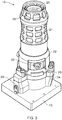
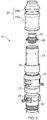
- Figures 3 to 5 show respectively perspective, longitudinal cross-sectional and exploded views of one of the coupling units.
- the coupling unit 19 has a cylindrical electrical connector 20 for push-fit electrical connection in a forward axial direction of the unit to a mating cylindrical electrical connector of the EEC 12.
- the electrical connector 20 contains an array of electrical prongs or sockets, while the mating electrical connector contains a corresponding array of sockets or prongs.
- Electrical leads extend rearwardly from the electrical connector 20 through a cylindrical backshell 21 of the coupling unit to join the bundle of flexible cables 13.
- the backshell is in a fixed rotational relationship with the electrical connector 20.
- the electrical connector 20 has a key or keyway 22 formed in a wall thereof which fits to a corresponding keyway or key of the mating electrical connector of the EEC 12 when the electrical connector 20 and the mating electrical connector are rotationally aligned.
- the push-fit connection of the connectors can only take place when this alignment is achieved.
- the coupling unit 19 further has a coaxial actuation sleeve 23 surrounding the backshell 21.
- the actuation sleeve is axially movable by the drive arrangement 16 to effect the push-fit connection of the connectors.
- the actuation sleeve has mounting formations 24 by which the sleeve can be mounted to the platform 15.
- the backshell 21 has an abutment formation in the form of a shoulder 32 which can engage with a corresponding abutment formation in the form of a narrowing 33 in the bore of the actuation sleeve 23 to prevent the backshell from being pulled forwardly out of the actuation sleeve.
- a coaxial hood 25 surrounds the electrical connector 20.
- the hood can be formed in two parts: a lower part 25a surrounds the bottom of the connector 20 and also an upper part of the backshell 21, while a top part 25b surrounds the top of the connector 20.
- the top part 25b alone can thus be easily replaced if worn.
- a circlip 26 attached to the backshell prevents the lower part 25a from sliding off the unit in a forward axial direction.
- the hood can have weight-saving apertures formed in it, as shown in Figures 3 and 4 .
- a first wave spring 27 is located between the backshell 21 and the actuation sleeve 23, and a second wave spring 28 is located between the actuation sleeve 23 and the coaxial hood 25.
- the first wave spring 27 typically has a spring force which is about four times that of the second wave spring 28.
- the backshell 21 and the actuation sleeve 23 are also operatively connected by three circumferentially distributed cam formations.
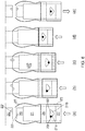
- Each cam formation comprises a pin 29 which extends radially outwardly from the backshell and a triangular opening 30 formed in the actuation sleeve which provides V-shaped first 31a and second 31b angled cam surfaces, described below with reference to Figure 6 .
- the lower section of the coupling unit shown in Figures 3 to 5 can be a generic sub-assembly able to carry a range of different upper sections (i.e. the electrical connector 20 and the hood 25) suitable for testing different EECs 12.
- the unit is presented to a mating connector 20' of the EEC 12.
- the key or keyway 22 of the connector 20 is rotationally misaligned with the corresponding keyway or key 22' of the mating connector 20'.
- the connector 20 rotates in one direction or the other depending on whether the pin 29 of each cam formation is positioned at either its first 31a or its second 31b cam surface.
- cam surface is the first cam surface 31a.
- Another option is to introduce at set up a torsional pre-tension to the electrical leads which, in use, extend rearwardly from the electrical connector 20 through the backshell 21 before joining the bundle of flexible cables 13. In this way, the backshell 21 can be biased to automatically rotate the pins 29 to the beginning of the desired cam surface.
- the actuation sleeve 23 is then moved axially forward, at this stage bringing the rest of the coupling unit forward with it.
- the coaxial hood 25 has a chamfered top part which engages the mating electrical connector 20' to axially align the electrical connector 20 with the mating electrical connector, although the keys and keyways 22, 22' remain rotationally misaligned.
- the second wave spring 28 cushions the engagement of the hood with the mating electrical connector. Compression of the second wave spring is indicated in Figure 6(a) to (e) by progressively darker shading.
- Alignment of the key and keyway 22, 22' also brings the electrical prongs and sockets of the connectors 20, 20' into alignment. However, the key and keyway arrangement prevents any load being applied to the prongs and sockets until that point.
- the actuation sleeve 23 is simply moved in the rearward axial direction, as shown in Figure 6(e) .
- the shoulder 32 of the backshell 21 engages with the narrowing 33 in the bore of the actuation sleeve to prevent the backshell and the connector 20 being left behind by this rearward movement.
- the second wave spring 28 unloads as the hood 25 disengages from the mating electrical connector 20'.
- the coupling unit is then ready to be presented to a mating connector of another EEC, the backshell 21 having first to be rotated in the actuation sleeve 23 to re-position the pins 29 at the beginning of the desired cam surface 31a, 31b.
- the overall length of such a coupling unit may be in the range from 150 to 300 mm, and the diameter may be in the range from 40 to 80 mm.
- a forward axial movement of the actuation sleeve 23 producing a compression of about 12 mm in the first wave spring 27 can generate an approximately 10° total rotation of the backshell 21 and the connector 20. This can assure alignment of the key and keyways 22, 22' and enables reliable and simply actuatable connection of plural such coupling units to respective mating connectors of the EEC 12.
- the hood 25 can provide about 2 mm of mismatch tolerance between the connectors 20, 20' transversely to the axial direction of the unit.
- the first wave spring 27 may have a spring in the range from 3.5 to 5.5 N/mm
- the second wave spring 28 may have a spring in the range from 1.0 to 1.25 N/mm.
- the non-electrically conducting components of the coupling unit can be formed by additive layer manufacturing (e.g. 3D printing).
- additive layer manufacturing e.g. 3D printing
- the unit can be formed largely out of plastic, such as polyetherimide, which can reduce weight while providing adequate thermal shielding of the internal unit components from high temperature in the test chamber 11.
- the coupling unit can be deployed at any angular orientation, and can incorporate a wide variety of connector types.
- Each slot-shaped opening 30' provides only one cam surface 31a for rotating the backshell 21 and bringing the key and keyway 22, 22' into alignment. Thus only one rotation direction is possible on connection.
- each slot-shaped opening 30' has an opposing cam surface 31c for counter-rotating the backshell on disconnection. More particularly, the stages of connection shown in Figures 7(a) to (c) match those shown in Figures 6(a) to (c) . However, once the key and keyway 22, 22' are aligned, as shown in Figure 7(d) , the load on first wave spring 27 cannot release as the pins 29 abut the opposing cam surfaces 31c, which stops the backshell moving axially forwardly relative to the actuation sleeve 23.
- the connectors 20, 20' are push-fitted together by continued forward movement of the actuation sleeve.
- the connector 20 and backshell 21 become free to rotate.
- the first wave spring 27 thus unloads forcing the pins 29 to slide along the opposing cam surfaces 31c and counter-rotating the connector 20 and backshell 21 back to their start position.
- FIG 8 shows schematically the mounting and drive arrangements for an array of the coupling units 19.
- the units are securely mounted to a platform 15 with the connectors facing upwards, and the EEC is mounted to a facing platform 17 with its mating connectors facing downwards.
- the two platforms are held in a rigid frame at the underside of the environmental test chamber (not shown in Figure 8 ), the frame incorporating a number of slides 18 allowing the mounting platform 15 to move up and down relative to the EEC platform 17.
- the drive arrangement 16 in the form of hydraulically or electrically operated pistons controlled by the testing control unit 14 moves the mounting platform 15 up and down and thus cause the repeated push-fit connection and disconnection of the electrical connectors of the coupling units and the mating electrical connectors of the EEC, with force being applied to the coupling units 19 only in the direction parallel to the axes of the units.
- the pistons have moved a certain distance upwards, the connectors become fully engaged and the passing off test is run.
- the pistons are generally not at the upwards limit of their travel at this position, they can be used to maintain a clamping force on the connectors during the test.
- the testing control unit 14 commands the pistons to drive the mounting platform 15 downwards and the connectors are disengaged.
- the coupling units 19 are an important contributor to reducing the likelihood of damage to the EEC, its mating connectors and the flexible cables 13. They also promote testing automation, particularly if coupled with a transport system which could, without operator intervention, automatically connect the EEC to a series of test stations and/or automatically connect a series of EECs to a given test station. In such a system, an EEC which failed a test could be automatically rejected to a holding location, making room for a next EEC to be tested.
- the coupling units 19, being modular in nature, are also compatible with the testing of different types of EEC.
- units can be rapidly repurposed for use on a different mounting platform 15 requiring a different number and or different spatial pattern of units.
Landscapes
- Physics & Mathematics (AREA)
- General Physics & Mathematics (AREA)
- Engineering & Computer Science (AREA)
- Environmental & Geological Engineering (AREA)
- General Engineering & Computer Science (AREA)
- Details Of Connecting Devices For Male And Female Coupling (AREA)
- Aviation & Aerospace Engineering (AREA)
Claims (14)
- Elektrische Verbindungseinheit (19), die Folgendes umfasst:einen elektrischen Verbinder (20) für eine elektrische Steckverbindung in Achsenrichtung der Verbindungseinheit mit einem elektrischen Gegenverbinder (20') einer Empfangseinheit (12), wobei der elektrische Verbinder und der elektrische Gegenverbinder entsprechende Eingriffsanordnungen (22, 22') aufweisen, die die Steckverbindung nur dann erlauben, wenn der elektrische Verbinder in einer bestimmten Drehausrichtung rund um die Achsenrichtung mit dem elektrischen Gegenverbinder ist;ein Endgehäuse (21), das in einer fixierten Drehbeziehung mit dem elektrischen Verbinder ist und das sich von dort nach hinten erstreckt, um in Verwendung eine oder mehrere elektrische Leitungen aufzunehmen, die sich vom elektrischen Verbinder nach hinten erstrecken; undeine koaxiale Betätigungshülse (23), welche das Endgehäuse umgibt, wobei die Betätigungshülse in Achsenrichtung bewegbar ist, um die Steckverbindung auszuführen;wobei das Endgehäuse und die Betätigungshülse wirkverbunden sind, sodass: die Bewegung der Betätigungshülse in einer Achsenvorwärtsrichtung in Richtung der Empfangseinheit durch den Kontakt des elektrischen Verbinders mit dem elektrischen Gegenverbinder einen Widerstand erfährt, um eine Drehung des Endgehäuses zu erzeugen, wodurch der elektrische Verbinder mit dem elektrischen Gegenverbinder drehausgerichtet wird und die elektrische Steckverbindung des elektrischen Verbinders mit dem elektrischen Gegenverbinder bewirkt wird; unddadurch gekennzeichnet, dass das Endgehäuse und die Betätigungshülse durch eine oder mehrere Nockenanordnungen wirkverbunden sind, die bei Kontakt des elektrischen Verbinders mit dem elektrischen Gegenverbinder eine Achsenvorwärtsbewegung der Betätigungshülse in die Drehbewegung des Endgehäuses umwandeln.
- Elektrische Verbindungseinheit nach Anspruch 1, wobei die Eingriffsanordnung des elektrischen Verbinders einen Keil oder eine Keilnut (22) umfasst und die Eingriffsanordnung des elektrischen Gegenverbinders das jeweils andere aus Keil oder Keilnut (22') umfasst.
- Elektrische Verbindungseinheit nach Anspruch 1 oder 2, die mehrere Nockenanordnungen aufweist, die in Umfangsrichtung um die Einheit verteilt sind.
- Elektrische Verbindungseinheit nach einem der vorangegangenen Ansprüche, wobei die oder jede Nockenanordnung einen Nockenstößel (29), der von dem Endgehäuse oder der Betätigungshülse bereitgestellt ist, und eine erste Nockenoberfläche (31a), die von dem jeweils anderen aus Endgehäuse oder Betätigungshülse bereitgestellt ist, entlang derer sich der Nockenstößel bewegt, aufweist, wobei die erste Nockenoberfläche derart abgewinkelt ist, dass sich das Endgehäuse relativ zur Betätigungshülse in Achsenrichtung rückwärts bewegt, wenn das Endgehäuse rotiert.
- Elektrische Verbindungseinheit nach Anspruch 4, wobei die oder jede Nockenanordnung weiters eine alternative zweite abgewinkelte Nockenoberfläche (31b) umfasst, die bei Kontakt des elektrischen Verbinders mit dem elektrischen Gegenverbinder eine Achsenvorwärtsbewegung der Betätigungshülse in die Drehbewegung des Endgehäuses, jedoch in die entgegengesetzte Rotationsrichtung, umwandelt;
wobei der Nockenstößel entweder an der ersten oder an der zweiten Nockenoberfläche auswählbar positionierbar ist, um die Drehrichtung des Endgehäuses auszuwählen. - Elektrische Verbindungseinheit nach einem der vorangegangenen Ansprüche, wobei das Endgehäuse und die Betätigungshülse durch eine erste Federanordnung (27), die durch eine Achsenrückwärtsbewegung des Endgehäuses relativ zur Betätigungshülse gespannt wird, wirkverbunden sind, um den Kontakt des elektrischen Verbinders mit der elektrischen Gegenverbinder-Hülse abzufedern.
- Elektrische Verbindungseinheit nach Anspruch 6, wobei die erste Federanordnung eine Wellfeder ist, die zur Verbindungseinheit koaxial ist.
- Elektrische Verbindungseinheit nach einem der vorangegangenen Ansprüche, die ferner eine Koaxialhaube (25) aufweist, die rund um den elektrische Verbinder angeordnet ist, wobei die Haube den elektrischen Gegenverbinder bei Achsenvorwärtsbewegung der Betätigungshülse in Eingriff bringt, um den elektrischen Verbinder mit dem elektrischen Gegenverbinder in Achsenrichtung auszurichten, bevor der elektrische Verbinder mit dem elektrischen Gegenverbinder in Kontakt tritt.
- Elektrische Verbindungseinheit nach Anspruch 8, wobei die Haube auf der Betätigungshülse durch eine zweite Federanordnung (28), die den Eingriff der Haube mit dem elektrischen Gegenverbinder abfedert, federnd gelagert ist.
- Elektrische Verbindungseinheit nach Anspruch 9, wobei die zweite Federanordnung eine Wellfeder ist, die koaxial zur Verbindungseinheit ist.
- Testvorrichtung für wiederholte Verbindung und Verbindungstrennung von elektrischen Verbindern, wobei die Testvorrichtung Folgendes aufweist:eine erste Befestigungsplattform (15);eine Anordnung aus Verbindungseinheiten nach einem der vorangegangenen Ansprüche, die über ihre jeweiligen Betätigungshülsen auf der ersten Befestigungsplattform befestigt ist;elektrische Leitungen (13), die sich von den elektrischen Verbindern der Verbindungseinheiten nach hinten erstrecken;eine zweite Befestigungsplattform (17) zum Befestigen einer Empfangseinheit (12) mit elektrischen Gegenverbindern, um mit den elektrischen Verbindern der Verbindungseinheiten steckverbunden zu werden; undeine Antriebsanordnung (16), die so steuerbar ist, dass sie die erste Befestigungsplattform in Achsenrichtungen der Verbindungseinheiten bewegt.
- Testvorrichtung nach Anspruch 11, die weiters eine Steuereinheit (14) umfasst, die die Antriebsanordnung steuert, die elektrischen Leitungen empfängt und dafür angepasst ist, so die Empfangseinheit elektrisch zu testen.
- Testvorrichtung nach Anspruch 11 oder 12, die weiters eine Umgebungstestkammer (11) umfasst, in der die Empfangseinheit angeordnet ist, wenn sie an der zweiten Befestigungsplattform befestigt ist, wobei die Testkammer einen oder mehrere Parameter steuert, die aus der folgenden Gruppe ausgewählt ist/sind: Temperatur innerhalb der Kammer, Feuchtigkeit innerhalb der Kammer, Luftdruck innerhalb der Kammer sowie mechanische Schwingung, die auf die Empfangseinheit aufgebracht wird.
- Verwendung der Testvorrichtung nach Anspruch 11 bis 13 zum Testen einer elektronischen Flugzeugmotorsteuerung als Empfangseinheit.
Applications Claiming Priority (1)
| Application Number | Priority Date | Filing Date | Title |
|---|---|---|---|
| GBGB1504860.6A GB201504860D0 (en) | 2015-03-23 | 2015-03-23 | Electrical coupling unit |
Publications (2)
| Publication Number | Publication Date |
|---|---|
| EP3073580A1 EP3073580A1 (de) | 2016-09-28 |
| EP3073580B1 true EP3073580B1 (de) | 2018-08-01 |
Family
ID=53052226
Family Applications (1)
| Application Number | Title | Priority Date | Filing Date |
|---|---|---|---|
| EP16156928.0A Active EP3073580B1 (de) | 2015-03-23 | 2016-02-23 | Elektrische kupplungseinheit |
Country Status (4)
| Country | Link |
|---|---|
| US (1) | US9876315B2 (de) |
| EP (1) | EP3073580B1 (de) |
| GB (2) | GB201504860D0 (de) |
| SG (1) | SG10201601716XA (de) |
Families Citing this family (2)
| Publication number | Priority date | Publication date | Assignee | Title |
|---|---|---|---|---|
| EP4215790B1 (de) | 2022-01-19 | 2025-11-19 | Goodrich Actuation Systems SAS | Steckverbinder |
| CN118858901B (zh) * | 2024-09-20 | 2024-12-24 | 圆周率半导体(南通)有限公司 | 一种pcb线路板分板循环检测装置及检测方法 |
Family Cites Families (11)
| Publication number | Priority date | Publication date | Assignee | Title |
|---|---|---|---|---|
| US3609632A (en) * | 1968-08-19 | 1971-09-28 | Trw Inc | Releasable electrical connector |
| FR2376533A1 (fr) * | 1976-12-31 | 1978-07-28 | Socapex | Connecteur multivoies a detrompage automatique |
| US4239325A (en) * | 1979-04-12 | 1980-12-16 | Tyson Thomas E | Self-aligning multi-pin connector |
| DE3121330A1 (de) | 1981-05-29 | 1982-12-16 | A. Römheld GmbH & Co KG, 6312 Laubach | Palettenspannsystem fuer werkzeugmaschinen |
| DE3339650A1 (de) * | 1983-11-02 | 1985-05-09 | Siemens AG, 1000 Berlin und 8000 München | Kupplungsvorrichtung zum axialen verbinden von zwei teilen einer zahnaerztlichen handstueckanordnung |
| US4667743A (en) | 1985-12-12 | 1987-05-26 | Halliburton Company | Low pressure responsive tester valve with ratchet |
| US5417459A (en) | 1994-02-24 | 1995-05-23 | Sonsub, Inc. | Subsea umbilical connector |
| US6305963B1 (en) * | 1996-08-16 | 2001-10-23 | Agilent Technologies, Inc. | Push-lock BNC connector |
| DE10163104A1 (de) | 2001-12-20 | 2003-07-03 | Roemheld A Gmbh & Co Kg | Zentrierspannelement |
| US20070178767A1 (en) | 2006-01-30 | 2007-08-02 | Harshman E S | Electrical connector |
| EP2779321B1 (de) * | 2013-03-13 | 2018-11-07 | Amphenol Corporation | Entkopplungsschutz für Verbinderelement |
-
2015
- 2015-03-23 GB GBGB1504860.6A patent/GB201504860D0/en not_active Ceased
-
2016
- 2016-02-23 EP EP16156928.0A patent/EP3073580B1/de active Active
- 2016-02-24 GB GB1603185.8A patent/GB2537963B/en active Active
- 2016-03-04 SG SG10201601716XA patent/SG10201601716XA/en unknown
- 2016-03-21 US US15/075,514 patent/US9876315B2/en active Active
Also Published As
| Publication number | Publication date |
|---|---|
| SG10201601716XA (en) | 2016-10-28 |
| US9876315B2 (en) | 2018-01-23 |
| GB2537963A (en) | 2016-11-02 |
| US20160285201A1 (en) | 2016-09-29 |
| GB2537963B (en) | 2018-02-28 |
| GB201603185D0 (en) | 2016-04-06 |
| EP3073580A1 (de) | 2016-09-28 |
| GB201504860D0 (en) | 2015-05-06 |
Similar Documents
| Publication | Publication Date | Title |
|---|---|---|
| EP2590270B1 (de) | Elektrischer Kabelbaum | |
| EP2590267B1 (de) | Stecker für elektrischen Kabelbaum | |
| EP2180225B1 (de) | Vorrichtung zum Verbinden von Rohren | |
| EP2671803B1 (de) | System und Verfahren zum Verbinden zweier Raumschiffe als Ladung | |
| US9365125B2 (en) | Plug connector | |
| US9876315B2 (en) | Electrical coupling unit | |
| US6358075B1 (en) | Mating alignment guide | |
| KR20080045552A (ko) | 전기 커넥터 및 커넥터 조립체 | |
| CA2486802A1 (en) | Connectors, instrument assemblies and methods of connecting or disconnecting electrical connections under power | |
| US2775745A (en) | Breakaway electrical connector | |
| US10345530B2 (en) | Alignment assembly and subsea fiber optical connector | |
| US20170188479A1 (en) | Terminal block for an electronic device | |
| WO2019139797A1 (en) | Blind-mate pim testing adapter connector and fixture | |
| CA3007616A1 (en) | Plug connector | |
| RS62651B1 (sr) | Kontakt utikača i postupak za ispitivanje mehanizma zaporke kontakta utikača | |
| US20210311263A1 (en) | Non-Rigid Blind Mate Connector System | |
| JPH11204194A (ja) | 電気コネクタ | |
| US20190322341A1 (en) | Fail free remotely operated vehicle | |
| US9658972B1 (en) | Universal pull-through receiver | |
| KR102179449B1 (ko) | 모듈형 커넥터 | |
| RU2188487C2 (ru) | Узел стыковки электрических цепей отсеков ракеты | |
| US20250368329A1 (en) | Advanced helmet vehicle interface connector with explosive atmosphere protection | |
| US10304588B2 (en) | Cable harness configurable from a neutral state to one of at least two configuration settings | |
| CN210040665U (zh) | 微型同轴连接器 | |
| HK1179421B (en) | Electrical harness |
Legal Events
| Date | Code | Title | Description |
|---|---|---|---|
| PUAI | Public reference made under article 153(3) epc to a published international application that has entered the european phase |
Free format text: ORIGINAL CODE: 0009012 |
|
| AK | Designated contracting states |
Kind code of ref document: A1 Designated state(s): AL AT BE BG CH CY CZ DE DK EE ES FI FR GB GR HR HU IE IS IT LI LT LU LV MC MK MT NL NO PL PT RO RS SE SI SK SM TR |
|
| AX | Request for extension of the european patent |
Extension state: BA ME |
|
| RAP1 | Party data changed (applicant data changed or rights of an application transferred) |
Owner name: ROLLS-ROYCE PLC |
|
| STAA | Information on the status of an ep patent application or granted ep patent |
Free format text: STATUS: REQUEST FOR EXAMINATION WAS MADE |
|
| 17P | Request for examination filed |
Effective date: 20170308 |
|
| RBV | Designated contracting states (corrected) |
Designated state(s): AL AT BE BG CH CY CZ DE DK EE ES FI FR GB GR HR HU IE IS IT LI LT LU LV MC MK MT NL NO PL PT RO RS SE SI SK SM TR |
|
| GRAP | Despatch of communication of intention to grant a patent |
Free format text: ORIGINAL CODE: EPIDOSNIGR1 |
|
| STAA | Information on the status of an ep patent application or granted ep patent |
Free format text: STATUS: GRANT OF PATENT IS INTENDED |
|
| RIC1 | Information provided on ipc code assigned before grant |
Ipc: H01R 13/629 20060101AFI20180126BHEP Ipc: H01R 13/635 20060101ALN20180126BHEP Ipc: H01R 13/631 20060101ALI20180126BHEP |
|
| GRAJ | Information related to disapproval of communication of intention to grant by the applicant or resumption of examination proceedings by the epo deleted |
Free format text: ORIGINAL CODE: EPIDOSDIGR1 |
|
| STAA | Information on the status of an ep patent application or granted ep patent |
Free format text: STATUS: REQUEST FOR EXAMINATION WAS MADE |
|
| INTG | Intention to grant announced |
Effective date: 20180212 |
|
| GRAP | Despatch of communication of intention to grant a patent |
Free format text: ORIGINAL CODE: EPIDOSNIGR1 |
|
| STAA | Information on the status of an ep patent application or granted ep patent |
Free format text: STATUS: GRANT OF PATENT IS INTENDED |
|
| INTC | Intention to grant announced (deleted) | ||
| RIC1 | Information provided on ipc code assigned before grant |
Ipc: H01R 13/629 20060101AFI20180319BHEP Ipc: H01R 13/635 20060101ALN20180319BHEP Ipc: H01R 13/631 20060101ALI20180319BHEP |
|
| INTG | Intention to grant announced |
Effective date: 20180406 |
|
| GRAS | Grant fee paid |
Free format text: ORIGINAL CODE: EPIDOSNIGR3 |
|
| GRAA | (expected) grant |
Free format text: ORIGINAL CODE: 0009210 |
|
| STAA | Information on the status of an ep patent application or granted ep patent |
Free format text: STATUS: THE PATENT HAS BEEN GRANTED |
|
| AK | Designated contracting states |
Kind code of ref document: B1 Designated state(s): AL AT BE BG CH CY CZ DE DK EE ES FI FR GB GR HR HU IE IS IT LI LT LU LV MC MK MT NL NO PL PT RO RS SE SI SK SM TR |
|
| REG | Reference to a national code |
Ref country code: GB Ref legal event code: FG4D |
|
| REG | Reference to a national code |
Ref country code: CH Ref legal event code: EP Ref country code: AT Ref legal event code: REF Ref document number: 1025441 Country of ref document: AT Kind code of ref document: T Effective date: 20180815 |
|
| REG | Reference to a national code |
Ref country code: IE Ref legal event code: FG4D |
|
| REG | Reference to a national code |
Ref country code: DE Ref legal event code: R096 Ref document number: 602016004354 Country of ref document: DE |
|
| REG | Reference to a national code |
Ref country code: NL Ref legal event code: MP Effective date: 20180801 |
|
| REG | Reference to a national code |
Ref country code: LT Ref legal event code: MG4D |
|
| REG | Reference to a national code |
Ref country code: AT Ref legal event code: MK05 Ref document number: 1025441 Country of ref document: AT Kind code of ref document: T Effective date: 20180801 |
|
| PG25 | Lapsed in a contracting state [announced via postgrant information from national office to epo] |
Ref country code: PL Free format text: LAPSE BECAUSE OF FAILURE TO SUBMIT A TRANSLATION OF THE DESCRIPTION OR TO PAY THE FEE WITHIN THE PRESCRIBED TIME-LIMIT Effective date: 20180801 Ref country code: IS Free format text: LAPSE BECAUSE OF FAILURE TO SUBMIT A TRANSLATION OF THE DESCRIPTION OR TO PAY THE FEE WITHIN THE PRESCRIBED TIME-LIMIT Effective date: 20181201 Ref country code: RS Free format text: LAPSE BECAUSE OF FAILURE TO SUBMIT A TRANSLATION OF THE DESCRIPTION OR TO PAY THE FEE WITHIN THE PRESCRIBED TIME-LIMIT Effective date: 20180801 Ref country code: AT Free format text: LAPSE BECAUSE OF FAILURE TO SUBMIT A TRANSLATION OF THE DESCRIPTION OR TO PAY THE FEE WITHIN THE PRESCRIBED TIME-LIMIT Effective date: 20180801 Ref country code: LT Free format text: LAPSE BECAUSE OF FAILURE TO SUBMIT A TRANSLATION OF THE DESCRIPTION OR TO PAY THE FEE WITHIN THE PRESCRIBED TIME-LIMIT Effective date: 20180801 Ref country code: BG Free format text: LAPSE BECAUSE OF FAILURE TO SUBMIT A TRANSLATION OF THE DESCRIPTION OR TO PAY THE FEE WITHIN THE PRESCRIBED TIME-LIMIT Effective date: 20181101 Ref country code: NL Free format text: LAPSE BECAUSE OF FAILURE TO SUBMIT A TRANSLATION OF THE DESCRIPTION OR TO PAY THE FEE WITHIN THE PRESCRIBED TIME-LIMIT Effective date: 20180801 Ref country code: SE Free format text: LAPSE BECAUSE OF FAILURE TO SUBMIT A TRANSLATION OF THE DESCRIPTION OR TO PAY THE FEE WITHIN THE PRESCRIBED TIME-LIMIT Effective date: 20180801 Ref country code: FI Free format text: LAPSE BECAUSE OF FAILURE TO SUBMIT A TRANSLATION OF THE DESCRIPTION OR TO PAY THE FEE WITHIN THE PRESCRIBED TIME-LIMIT Effective date: 20180801 Ref country code: GR Free format text: LAPSE BECAUSE OF FAILURE TO SUBMIT A TRANSLATION OF THE DESCRIPTION OR TO PAY THE FEE WITHIN THE PRESCRIBED TIME-LIMIT Effective date: 20181102 Ref country code: NO Free format text: LAPSE BECAUSE OF FAILURE TO SUBMIT A TRANSLATION OF THE DESCRIPTION OR TO PAY THE FEE WITHIN THE PRESCRIBED TIME-LIMIT Effective date: 20181101 |
|
| PG25 | Lapsed in a contracting state [announced via postgrant information from national office to epo] |
Ref country code: LV Free format text: LAPSE BECAUSE OF FAILURE TO SUBMIT A TRANSLATION OF THE DESCRIPTION OR TO PAY THE FEE WITHIN THE PRESCRIBED TIME-LIMIT Effective date: 20180801 Ref country code: HR Free format text: LAPSE BECAUSE OF FAILURE TO SUBMIT A TRANSLATION OF THE DESCRIPTION OR TO PAY THE FEE WITHIN THE PRESCRIBED TIME-LIMIT Effective date: 20180801 Ref country code: AL Free format text: LAPSE BECAUSE OF FAILURE TO SUBMIT A TRANSLATION OF THE DESCRIPTION OR TO PAY THE FEE WITHIN THE PRESCRIBED TIME-LIMIT Effective date: 20180801 |
|
| PG25 | Lapsed in a contracting state [announced via postgrant information from national office to epo] |
Ref country code: ES Free format text: LAPSE BECAUSE OF FAILURE TO SUBMIT A TRANSLATION OF THE DESCRIPTION OR TO PAY THE FEE WITHIN THE PRESCRIBED TIME-LIMIT Effective date: 20180801 Ref country code: EE Free format text: LAPSE BECAUSE OF FAILURE TO SUBMIT A TRANSLATION OF THE DESCRIPTION OR TO PAY THE FEE WITHIN THE PRESCRIBED TIME-LIMIT Effective date: 20180801 Ref country code: IT Free format text: LAPSE BECAUSE OF FAILURE TO SUBMIT A TRANSLATION OF THE DESCRIPTION OR TO PAY THE FEE WITHIN THE PRESCRIBED TIME-LIMIT Effective date: 20180801 Ref country code: RO Free format text: LAPSE BECAUSE OF FAILURE TO SUBMIT A TRANSLATION OF THE DESCRIPTION OR TO PAY THE FEE WITHIN THE PRESCRIBED TIME-LIMIT Effective date: 20180801 Ref country code: CZ Free format text: LAPSE BECAUSE OF FAILURE TO SUBMIT A TRANSLATION OF THE DESCRIPTION OR TO PAY THE FEE WITHIN THE PRESCRIBED TIME-LIMIT Effective date: 20180801 |
|
| REG | Reference to a national code |
Ref country code: DE Ref legal event code: R097 Ref document number: 602016004354 Country of ref document: DE |
|
| PG25 | Lapsed in a contracting state [announced via postgrant information from national office to epo] |
Ref country code: SK Free format text: LAPSE BECAUSE OF FAILURE TO SUBMIT A TRANSLATION OF THE DESCRIPTION OR TO PAY THE FEE WITHIN THE PRESCRIBED TIME-LIMIT Effective date: 20180801 Ref country code: DK Free format text: LAPSE BECAUSE OF FAILURE TO SUBMIT A TRANSLATION OF THE DESCRIPTION OR TO PAY THE FEE WITHIN THE PRESCRIBED TIME-LIMIT Effective date: 20180801 Ref country code: SM Free format text: LAPSE BECAUSE OF FAILURE TO SUBMIT A TRANSLATION OF THE DESCRIPTION OR TO PAY THE FEE WITHIN THE PRESCRIBED TIME-LIMIT Effective date: 20180801 |
|
| PLBE | No opposition filed within time limit |
Free format text: ORIGINAL CODE: 0009261 |
|
| STAA | Information on the status of an ep patent application or granted ep patent |
Free format text: STATUS: NO OPPOSITION FILED WITHIN TIME LIMIT |
|
| 26N | No opposition filed |
Effective date: 20190503 |
|
| PG25 | Lapsed in a contracting state [announced via postgrant information from national office to epo] |
Ref country code: SI Free format text: LAPSE BECAUSE OF FAILURE TO SUBMIT A TRANSLATION OF THE DESCRIPTION OR TO PAY THE FEE WITHIN THE PRESCRIBED TIME-LIMIT Effective date: 20180801 |
|
| REG | Reference to a national code |
Ref country code: CH Ref legal event code: PL |
|
| PG25 | Lapsed in a contracting state [announced via postgrant information from national office to epo] |
Ref country code: MC Free format text: LAPSE BECAUSE OF FAILURE TO SUBMIT A TRANSLATION OF THE DESCRIPTION OR TO PAY THE FEE WITHIN THE PRESCRIBED TIME-LIMIT Effective date: 20180801 Ref country code: LU Free format text: LAPSE BECAUSE OF NON-PAYMENT OF DUE FEES Effective date: 20190223 |
|
| REG | Reference to a national code |
Ref country code: BE Ref legal event code: MM Effective date: 20190228 |
|
| REG | Reference to a national code |
Ref country code: IE Ref legal event code: MM4A |
|
| PG25 | Lapsed in a contracting state [announced via postgrant information from national office to epo] |
Ref country code: LI Free format text: LAPSE BECAUSE OF NON-PAYMENT OF DUE FEES Effective date: 20190228 Ref country code: CH Free format text: LAPSE BECAUSE OF NON-PAYMENT OF DUE FEES Effective date: 20190228 |
|
| PG25 | Lapsed in a contracting state [announced via postgrant information from national office to epo] |
Ref country code: IE Free format text: LAPSE BECAUSE OF NON-PAYMENT OF DUE FEES Effective date: 20190223 |
|
| PG25 | Lapsed in a contracting state [announced via postgrant information from national office to epo] |
Ref country code: BE Free format text: LAPSE BECAUSE OF NON-PAYMENT OF DUE FEES Effective date: 20190228 |
|
| PG25 | Lapsed in a contracting state [announced via postgrant information from national office to epo] |
Ref country code: TR Free format text: LAPSE BECAUSE OF FAILURE TO SUBMIT A TRANSLATION OF THE DESCRIPTION OR TO PAY THE FEE WITHIN THE PRESCRIBED TIME-LIMIT Effective date: 20180801 |
|
| PG25 | Lapsed in a contracting state [announced via postgrant information from national office to epo] |
Ref country code: PT Free format text: LAPSE BECAUSE OF FAILURE TO SUBMIT A TRANSLATION OF THE DESCRIPTION OR TO PAY THE FEE WITHIN THE PRESCRIBED TIME-LIMIT Effective date: 20181201 Ref country code: MT Free format text: LAPSE BECAUSE OF NON-PAYMENT OF DUE FEES Effective date: 20190223 |
|
| PG25 | Lapsed in a contracting state [announced via postgrant information from national office to epo] |
Ref country code: CY Free format text: LAPSE BECAUSE OF FAILURE TO SUBMIT A TRANSLATION OF THE DESCRIPTION OR TO PAY THE FEE WITHIN THE PRESCRIBED TIME-LIMIT Effective date: 20180801 |
|
| PG25 | Lapsed in a contracting state [announced via postgrant information from national office to epo] |
Ref country code: HU Free format text: LAPSE BECAUSE OF FAILURE TO SUBMIT A TRANSLATION OF THE DESCRIPTION OR TO PAY THE FEE WITHIN THE PRESCRIBED TIME-LIMIT; INVALID AB INITIO Effective date: 20160223 |
|
| PG25 | Lapsed in a contracting state [announced via postgrant information from national office to epo] |
Ref country code: MK Free format text: LAPSE BECAUSE OF FAILURE TO SUBMIT A TRANSLATION OF THE DESCRIPTION OR TO PAY THE FEE WITHIN THE PRESCRIBED TIME-LIMIT Effective date: 20180801 |
|
| P01 | Opt-out of the competence of the unified patent court (upc) registered |
Effective date: 20230528 |
|
| PGFP | Annual fee paid to national office [announced via postgrant information from national office to epo] |
Ref country code: GB Payment date: 20260223 Year of fee payment: 11 |
|
| PGFP | Annual fee paid to national office [announced via postgrant information from national office to epo] |
Ref country code: DE Payment date: 20260220 Year of fee payment: 11 |
|
| PGFP | Annual fee paid to national office [announced via postgrant information from national office to epo] |
Ref country code: FR Payment date: 20260224 Year of fee payment: 11 |