EP3073484A1 - Support assembly and keyboard apparatus - Google Patents
Support assembly and keyboard apparatus Download PDFInfo
- Publication number
- EP3073484A1 EP3073484A1 EP16161151.2A EP16161151A EP3073484A1 EP 3073484 A1 EP3073484 A1 EP 3073484A1 EP 16161151 A EP16161151 A EP 16161151A EP 3073484 A1 EP3073484 A1 EP 3073484A1
- Authority
- EP
- European Patent Office
- Prior art keywords
- support
- repetition lever
- support assembly
- spring element
- jack
- Prior art date
- Legal status (The legal status is an assumption and is not a legal conclusion. Google has not performed a legal analysis and makes no representation as to the accuracy of the status listed.)
- Granted
Links
Images



Classifications
-
- G—PHYSICS
- G10—MUSICAL INSTRUMENTS; ACOUSTICS
- G10C—PIANOS, HARPSICHORDS, SPINETS OR SIMILAR STRINGED MUSICAL INSTRUMENTS WITH ONE OR MORE KEYBOARDS
- G10C3/00—Details or accessories
- G10C3/16—Actions
- G10C3/24—Repetition [tremolo] mechanisms
-
- G—PHYSICS
- G10—MUSICAL INSTRUMENTS; ACOUSTICS
- G10C—PIANOS, HARPSICHORDS, SPINETS OR SIMILAR STRINGED MUSICAL INSTRUMENTS WITH ONE OR MORE KEYBOARDS
- G10C3/00—Details or accessories
- G10C3/16—Actions
-
- G—PHYSICS
- G10—MUSICAL INSTRUMENTS; ACOUSTICS
- G10C—PIANOS, HARPSICHORDS, SPINETS OR SIMILAR STRINGED MUSICAL INSTRUMENTS WITH ONE OR MORE KEYBOARDS
- G10C3/00—Details or accessories
- G10C3/16—Actions
- G10C3/18—Hammers
-
- G—PHYSICS
- G10—MUSICAL INSTRUMENTS; ACOUSTICS
- G10C—PIANOS, HARPSICHORDS, SPINETS OR SIMILAR STRINGED MUSICAL INSTRUMENTS WITH ONE OR MORE KEYBOARDS
- G10C3/00—Details or accessories
- G10C3/16—Actions
- G10C3/22—Actions specially adapted for grand pianos
Definitions
- the present invention relates to a support assembly for use in a keyboard apparatus.
- Conventional acoustic pianos such as grand pianos and upright pianos are configured of many components. Also, since assembling these components is very complex, the assembling operation takes a long time. In particular, since an action mechanism provided for each key requires many components, its assembling operation is very complex.
- a support assembly configuring part of the action mechanism operates with various components assembled together.
- the support assembly has not only a mechanism which achieves string hammering by the hammer in accordance with key pressing but also an escapement mechanism for releasing a force transmitted to the hammer by key operation immediately before string hammering.
- This mechanism is an important mechanism for the basic operation of an acoustic piano.
- a double escapement mechanism with a repetition lever and a jack combined together is generally adopted.
- the operation of the action mechanism provides a sense (hereinafter referred to as a touch feeling) to a finger of a player through the key.
- a touch feeling a sense
- the structure of the support assembly has an important influence on the touch feeling.
- let-off the touch feeling by the operation of the escapement mechanism is called let-off.
- One object of the present invention is to reduce manufacturing cost of a support assembly while decreasing a change in touch feeling at the time of key operation, compared with a keyboard apparatus of an acoustic piano.
- a support assembly which includes a support rotatably disposed with respect to a frame, a repetition lever rotatably connected to the support, an spring element supported by a support portion fixed to the support, the spring element providing a rotational force to the repetition lever, and a contact portion between the repetition lever and the spring element, wherein a rotating portion of the repetition lever is provided with respect to the support portion on a side opposite to the contact portion between the repetition lever and the spring element.
- the contact portion may include a protrusion.
- a position may be provided where the repetition lever and the spring element become parallel to each other.
- the region with flexibility of the repetition lever may be a spring element.
- a keyboard apparatus which includes a plurality of the support assemblies according to claim 1, keys disposed correspondingly to the respective support assemblies to rotate the support, and a sound emission mechanism which emits sound in accordance with key pressing.
- FIG. 1 is a side view depicting a mechanical structure of the keyboard apparatus according to one embodiment of the present invention.
- the keyboard apparatus 1 according to one embodiment of the present invention includes a plurality of keys 110 (in this example, eighty-eight keys) and an action mechanism for each of the keys 110.
- the action mechanism includes a support assembly 20, a hammer shank 310, a hammer 320, and a hammer stopper 410.
- FIG. 1 depicts the case in which the key 110 is white key, the key may be a black key.
- orientations such as a forward side, a deeper side, upward, downward, and sideward from a player are defined as orientations when the keyboard apparatus is viewed from a player's side.
- the support assembly 20 is disposed on a player's forward side when viewed from the hammer 320, and is disposed upward when viewed from the key 110.
- Sideward corresponds to a direction in which the keys 110 are arranged.
- the support assembly 20 includes a support 210, a repetition lever 240, the jack 250, and the torsion coil spring 280 which is a spring element.
- the support 210 and the repetition lever 240 are coupled together via a flexible portion 220.
- the repetition lever 240 is rotatably supported with respect to the support 210.
- the support assembly 20, except the torsion coil spring 280 and cushioning materials or the like (such as nonwoven fabric or spring element) provided at a portion which collides with another member, is a resin-made structure manufactured by injection molding.
- the support 210 and the repetition lever 240 are integrally formed. Note that the support 210 and the repetition lever 240 may be formed as individual components and be attached or bonded together.
- the large jack 2502 includes linear-shaped protrusions P2 projecting from both side surfaces.
- the protrusions P2 slidably contact the protrusions P1 of the inner portion 2441 described above.
- the small jack 2504 includes circular-shaped protrusions P3 projecting from both side surfaces.
- the protrusions P3 slidably contact an inner surface of the coupling portion 2443 described above.
- a contact area is decreased.
- a grease reservoir may be formed by forming a groove portion by a plurality of protrusions P2.
- a protrusion or groove portion may be formed in a side-surface of the large jack 2502.
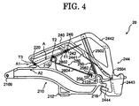
- FIG. 4 is a side view depicting a positional relation of each structure of the support assembly in one embodiment of the present invention.
- the spring contact portion 242 is provided at the protrusion provided to the repetition lever 240.
- the spring contact portion 242 functions as a point of action of the repetition lever.
- the first arm 2802 which is a spring element, is a straight-line-shaped member, and may be slightly bent in accordance with rotation of the repetition lever 240.
- the support assembly 20 is described when the key 110 is pressed down from the rest position ( Fig. 1 ) to the end position.
- FIG. 7 is a block diagram depicting the structure of a sound emission mechanism of the keyboard apparatus according to one embodiment of the present invention.
- a sound emission mechanism 50 of the keyboard apparatus 1 includes the sensors 510 (sensors 510-1, 510-2, ... 510-88 for the eighty-eight keys 110), a signal converting unit 550, a sound source unit 560, and an output unit 570.
- the signal converting unit 550 obtains an electric signal outputted from the sensor 510, and generates and outputs an operation signal in accordance with an operating state in each key 110.
- the operation signal is a MIDI-format signal.
Landscapes
- Physics & Mathematics (AREA)
- Engineering & Computer Science (AREA)
- Acoustics & Sound (AREA)
- Multimedia (AREA)
- Electrophonic Musical Instruments (AREA)
Abstract
Description
- This application is based upon and claims the benefit of priority from the prior Japanese Patent Application No.
2015-063274, filed on March 25, 2015 - The present invention relates to a support assembly for use in a keyboard apparatus.
- Conventional acoustic pianos such as grand pianos and upright pianos are configured of many components. Also, since assembling these components is very complex, the assembling operation takes a long time. In particular, since an action mechanism provided for each key requires many components, its assembling operation is very complex.
- For example, in an action mechanism described in Japanese Unexamined Patent Application Publication No.
2005-292361 - The operation of the action mechanism provides a sense (hereinafter referred to as a touch feeling) to a finger of a player through the key. In particular, the structure of the support assembly has an important influence on the touch feeling. For example, the touch feeling by the operation of the escapement mechanism is called let-off.
- Since the number of respective components making up the support assembly is large, the manufacturing period is prolonged, and manufacturing cost increased. Therefore, to reduce manufacturing cost, it is desired to simply decrease the number of components and the structure. However, if the structure of the support assembly is changed, the touch feeling at the time of key operation is greatly changed. Therefore, it is difficult to decrease the expense of manufacturing an acoustic piano.
- One object of the present invention is to reduce manufacturing cost of a support assembly while decreasing a change in touch feeling at the time of key operation, compared with a keyboard apparatus of an acoustic piano.
- According to one embodiment of the present invention, a support assembly is provided which includes a support rotatably disposed with respect to a frame, a repetition lever rotatably connected to the support, an spring element supported by a support portion fixed to the support, the spring element providing a rotational force to the repetition lever, and a contact portion between the repetition lever and the spring element, wherein a rotating portion of the repetition lever is provided with respect to the support portion on a side opposite to the contact portion between the repetition lever and the spring element.
- The rotating portion of the repetition lever may be provided on an extension line of a straight line connecting the support portion and the contact portion.
- The contact portion may include a protrusion.
- In a rotation range of the repetition lever, a position may be provided where the repetition lever and the spring element become parallel to each other.
- The spring element may be a wire spring.
- In a rotation range of the repetition lever, the repetition lever and the straight-line-shaped portion of the spring element may be positioned at an angle in a range equal to or larger than 0° and equal to or smaller than 20°.
- The rotating portion of the repetition lever may include a flexible region.
- The region with flexibility of the repetition lever may be a spring element.
- The support may include a resin structure.
- The jack may include a resin structure.
- Also, according to one embodiment of the present embodiment, a keyboard apparatus may be provided, which includes a plurality of the support assemblies according to claim 1, keys disposed correspondingly to the respective support assemblies to rotate the support, and a sound emission mechanism which emits sound in accordance with key pressing.
- The sound emission mechanism may include a sound source unit generating a sound signal in accordance with key pressing.
- The sound emission mechanism may include a string generating a sound by colliding a hammer in accordance with key pressing.
-
-
FIG. 1 is a side view depicting the structure of a keyboard apparatus in one embodiment of the present invention; -
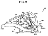
FIG. 2 is a side view depicting the structure of a support assembly in one embodiment of the present invention; -
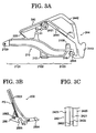
FIG. 3A is a side view depicting a partial structure of the disassembled support assembly in one embodiment of the present invention; -
FIG. 3B is a side view depicting a partial structure of the disassembled support assembly in one embodiment of the present invention; -
FIG. 3C is a side view depicting a partial structure of the disassembled support assembly in one embodiment of the present invention; -
FIG. 4 is a side view depicting a positional relation of each structure of the support assembly in one embodiment of the present invention; -
FIG. 5 is a side view for describing movement of the support assembly in one embodiment of the present invention; -
FIG. 6A is a side view for describing movement of the support assembly in one embodiment of the present invention; -
FIG. 6B is a side view for describing movement of the support assembly in one embodiment of the present invention; and -
FIG. 7 is a block diagram depicting the structure of a sound emission mechanism of the keyboard apparatus according to one embodiment of the present invention. - 1...keyboard apparatus, 110...key, 20...support assembly, 210...support, 2101...first main body portion, 2102...bent portion, 2103...second main body portion, 2105...jack support portion, 2109...through hole, 212...support heel, 216...stopper, 218...spring support portion, 220...flexible portion, 240...repetition lever, 242...spring contact portion, 2421...spring contact top portion, 2422...curved-surface portion, 2423...spring contact side portion, 2425...spring contact side portion, 244...extension portion, 2441...inner portion, 2442...outer section, 2443...coupling portion, 2444...stopper contact portion, 250...jack, 2502...large jack, 2504...small jack, 2505...support connecting portion, 280...torsion coil spring, 2802...first arm, 2804...second arm, 290...support flange, 310...hammer shank, 315...hammer roller, 320...hammer, 346...repetition regulating screw, 360...regulating button, 390...shank flange, 410...hammer stopper, 50...sound emission mechanism, 510...sensor, 520...shielding plate, 550...signal converting unit, 560...sound source unit, 570...output unit, 900...bracket, 910...balance rail, 920...frame, 930...shank rail, 940...hammer stopper rail, 950...sensor rail, 960...frame
- In the following, a keyboard apparatus including a support assembly in one embodiment of the present invention is described in detail with reference to the drawings. Embodiments described below are merely examples of embodiments of the present invention, and the present invention should not be interpreted to be restricted to these embodiments. Note that, in the drawings referred to in the present embodiments, identical portions or portions having a similar function are provided with a same sign or similar sign (sign with a numeral merely followed by A, B, or the like), and repetitive description thereof may be omitted. Also, for convenience of description, the dimensional ratio in the drawings (such as ratio between respective structures, or a ratio among length) may differ from an actual ratio, and part of the structure may be omitted from the drawings.
- A keyboard apparatus 1 in one embodiment of the present invention is an example obtained by applying one example of the support assembly according to the present invention to an electronic piano. To obtain a touch feeling close to a grand piano at the time of key operation, this electronic piano includes a structure similar to a support assembly included in a grand piano. By using
FIG. 1 , a general outline of the keyboard apparatus 1 according to one embodiment of the present invention is described. -
FIG. 1 is a side view depicting a mechanical structure of the keyboard apparatus according to one embodiment of the present invention. As depicted inFIG. 1 , the keyboard apparatus 1 according to one embodiment of the present invention includes a plurality of keys 110 (in this example, eighty-eight keys) and an action mechanism for each of thekeys 110. The action mechanism includes asupport assembly 20, ahammer shank 310, ahammer 320, and ahammer stopper 410. Note that whileFIG. 1 depicts the case in which the key 110 is white key, the key may be a black key. Also, in the following description, terms representing orientations such as a forward side, a deeper side, upward, downward, and sideward from a player are defined as orientations when the keyboard apparatus is viewed from a player's side. For example, in the example ofFIG. 1 , thesupport assembly 20 is disposed on a player's forward side when viewed from thehammer 320, and is disposed upward when viewed from the key 110. Sideward corresponds to a direction in which thekeys 110 are arranged. - The key 110 is rotatably supported by a
balance rail 910. The key 110 rotates in a range from a rest position depicted inFIG. 1 to an end position. The key 110 includes acapstan screw 120. Thesupport assembly 20 is rotatably connected to asupport flange 290, and is resting on thecapstan screw 120. Thesupport flange 290 is fixed to aframe 920. Detailed structure of thesupport assembly 20 will be described further below. Note that thesupport flange 290 and thesupport rail 920 are one example of a frame serving as a reference of rotation of thesupport assembly 20. The frame may be formed of a plurality of members, such as thesupport flange 290 and thesupport rail 920, or may be formed of one member. The frame may be, as with thesupport rail 920, a rail-shaped member with a long side in the arrangement direction of thekeys 110, or may be, as with thesupport flange 290, an independent member for each key 110. - The
hammer shank 310 is rotatably connected to ashank flange 390. Thehammer shank 310 includes ahammer roller 315. Thehammer shank 310 is mounted on thesupport assembly 20 via thehammer roller 315. Theshank flange 390 is fixed to ashank rail 930. Thehammer 320 is fixed to an end of thehammer shank 310. Aregulating button 360 is fixed to theshank rail 930. Thehammer stopper 410 is fixed to ahammer stopper rail 940 disposed at a position of regulating rotation of thehammer shank 310. - A
sensor 510 is a sensor for measuring the position and moving speed (speed immediately before thehammer shank 310 collides with the hammer stopper 410) of thehammer shank 310. Thesensor 510 is fixed to asensor rail 950. In this example, thesensor 510 is a photo interrupter. In accordance with the amount of shielding the optical axis of the photo interrupter by ashielding plate 520 fixed to thehammer shank 310, an output value from thesensor 510 is changed. Based on this output value, the position and moving speed of thehammer shank 310 can be measured. Note that a sensor for measuring an operating state of the key 110 may be provided in place of thesensor 510 or together with thesensor 510. - The above-described
frame 920,shank rail 930,hammer stopper rail 940, andsensor rail 950 are supported by abracket 900. -
FIG. 2 is a side view depicting the structure of the support assembly in one embodiment of the present invention.FIG. 3A to FIG. 3C are side views each depicting a partial structure of the disassembled support assembly in one embodiment of the present invention. For easy understanding of the features of each component,FIG. 3A is a drawing in which ajack 250 and atorsion coil spring 280 are excluded from thesupport assembly 20.FIG. 3B is a drawing only depicting thejack 250. - The
support assembly 20 includes asupport 210, arepetition lever 240, thejack 250, and thetorsion coil spring 280 which is a spring element. Thesupport 210 and therepetition lever 240 are coupled together via aflexible portion 220. By theflexible portion 220, therepetition lever 240 is rotatably supported with respect to thesupport 210. Thesupport assembly 20, except thetorsion coil spring 280 and cushioning materials or the like (such as nonwoven fabric or spring element) provided at a portion which collides with another member, is a resin-made structure manufactured by injection molding. In this example, thesupport 210 and therepetition lever 240 are integrally formed. Note that thesupport 210 and therepetition lever 240 may be formed as individual components and be attached or bonded together. - The
support 210 has one end side where a throughhole 2109 is formed, and has the other end side where ajack support portion 2105 is formed. Between the throughhole 2109 and thejack support portion 2105, thesupport 210 includes asupport heel 212 projecting downward and aspring support portion 218 projecting upward. Through thehole 2109, a shaft supported by thesupport flange 290 is drawn. With this, thesupport 210 is rotatably disposed with respect to thesupport flange 290 and theframe 920. Therefore, the throughhole 2109 serves as a rotation center of thesupport 210. - The
support heel 212 has its lower surface which makes contact with the above-describedcapstan screw 120. Thespring support portion 218 fixed to thesupport 210 supports thetorsion coil spring 280. Thejack support portion 2105 rotatably supports thejack 250. Therefore, thejack support portion 2105 serves as a rotation center of thejack 250. - Between the through hole 2109 (rotation center of the support 210) and the jack support portion 2105 (rotation center of the jack 250), a space is formed on a
jack support portion 2105 side from thesupport heel 212. For convenience of description, thesupport 210 is sectioned into regions: a firstmain body portion 2101, abent portion 2102, and a secondmain body portion 2103, from a throughhole 2109 side. In this case, by thebent portion 2102 which couples the firstmain body portion 2101 and the secondmain body portion 2103 together, the secondmain body portion 2103 is disposed on a side closer to the key 110 (downward) than the firstmain body portion 2101. Thejack support portion 2105 projects upward from the secondmain body portion 2103. According to this sectioning, the above-described space corresponds to a region interposed between thebent portion 2102 and thejack support portion 2105 above the secondmain body portion 2103. Also, at an end of the support 210 (an end on a secondmain body portion 2103 side), astopper 216 couples. Thesupport heel 212 is disposed below thebent portion 2102. Here, it is preferred that a distance from the key 110 to the secondmain body portion 2103 be longer than a distance from the key 110 to the support heel 212 (that is, the length of the capstan screw 130). This makes the capstan screw 130 easily adjustable from a player's side. - To the
repetition lever 240, aspring contact portion 242 and anextension portion 244 are coupled. Thespring contact portion 242 makes contact with afirst arm 2802 of thetorsion coil spring 280. Therepetition lever 240 and theextension portion 244 include two plate-shaped members for interposition from sides of both side surfaces of thejack 250. In this example, theextension portion 244 and thejack 250 slidably make contact with each other in at least part of a space interposed between these two plate-shaped members. Also, thespring contact portion 242 is a protrusion which projects from therepetition lever 240. In one embodiment, therepetition lever 240 and thespring contact portion 242 are integrally formed. - The
spring contact portion 242 is described in detail by usingFIG. 3C. FIG. 3C is a partially enlarged view of thespring contact portion 242 in a region X1 ofFIG. 3A viewed in a D1 direction. Thespring contact portion 242 is configured of a springcontact top portion 2421 and two springcontact side portion 2423 and springcontact side portion 2425 interposing the springcontact top portion 2421. The springcontact top portion 2421 includes a curved-surface portion 2422 at a portion of the springcontact top v 2421 which receives a force from thefirst arm 2802 to rotate therepetition lever 240. When therepetition lever 240 rotates, thefirst arm 2802 slidably moves on the curved-surface portion 2422. Here, since thefirst arm 2802 extends along a tangent line of the curved-surface 2422, thefirst arm 2802 and the curved-surface portion 2422 have a contact area which is very small, almost a point contact. - The spring
contact side portion 2423 and the springcontact side portion 2425 regulate movement of thefirst arm 2802 to a side-surface direction. Of the springcontact side portion 2423 and the springcontact side portion 2425, a surface which regulates movement of thefirst arm 2802 to the side-surface direction may form a curved surface. With this, as with the curved-surface portion 2422, a contact area with thefirst arm 2802 can also be reduced. Since a portion below the curved-surface portion 2422 is open, thefirst arm 2802 can be easily hooked to thespring contact portion 242. - The
extension portion 244 includes aninner portion 2441, anouter portion 2442, acoupling portion 2443, and astopper contact portion 2444. Theinner portion 2441 is coupled to therepetition lever 240 on a deeper side from a player (flexible portion 220 side) of alarge jack 2502. At a portion where theinner portion 2441 and therepetition lever 240 are coupled together, arib 246 is provided. Theinner portion 2441 interposes thelarge jack 2502 to cross to extend to a player's forward side (opposite side to the flexible portion 220) of thelarge jack 2502. At a portion of the intersection between theinner portion 2441 and thelarge jack 2502, theinner portion 2441 includes a linear-shaped protrusions P1 projecting to alarge jack 2502 side. - The
outer portion 2442 is coupled to therepetition lever 240 on a player's forward side (opposite side to the flexible portion 220) of the jack 250 (large jack 2502). Theinner portion 2441 and theouter portion 2442 are coupled together at thecoupling portion 2443. Thecoupling portion 2443 interposes asmall jack 2504. Thestopper contact portion 2444 couples to thecoupling portion 2443, and makes contact with thestopper 216 from below. According to this, the rotation range in a direction in which therepetition lever 240 and thesupport 210 spread is regulated. - The
jack 250 includes thelarge jack 2502, thesmall jack 2504, and a projectingportion 256. Thejack 250 is rotatably disposed with respect to thesupport 210. Between thelarge jack 2502 and thesmall jack 2504, asupport connecting portion 2505 to be rotatably supported by thejack support portion 2105 is formed. Thesupport connecting portion 2505 has a shape surrounding part of thejack support portion 2105, and regulates a rotation range of thejack 250. Also, with the shape of thesupport connecting portion 2505 and elastic deformation of its material, it is possible to fit thesupport connecting portion 2505 of thejack 250 into the jack support portion 2105from above thejack support portion 2105. The projectingportion 256 projects from thelarge jack 2502 to a side opposite to thesmall jack 2504, and rotates with thejack 250. The projectingportion 256 includes, on its side surface, aspring contact portion 2562. Thespring contact portion 2562 makes contact with asecond arm 2804 of thetorsion coil spring 280. - The
large jack 2502 includes linear-shaped protrusions P2 projecting from both side surfaces. The protrusions P2 slidably contact the protrusions P1 of theinner portion 2441 described above. Thesmall jack 2504 includes circular-shaped protrusions P3 projecting from both side surfaces. The protrusions P3 slidably contact an inner surface of thecoupling portion 2443 described above. As such, with thejack 250 and theextension portion 244 slidably contacting each other via the protrusions P1, P2, and P3, a contact area is decreased. Note that a grease reservoir may be formed by forming a groove portion by a plurality of protrusions P2. Also, a protrusion or groove portion may be formed in a side-surface of thelarge jack 2502. - In the
torsion coil spring 280, thespring support portion 218 is taken as a fulcrum, thefirst arm 2802 makes contact with thespring contact portion 242, and thesecond arm 2804 makes contact with thespring contact portion 2562. Thefirst arm 2802 functions as an spring element which provides a rotational force to therepetition lever 240 via thespring contact portion 242 so as to move a player's side of therepetition lever 240 upward (in a direction away from the support 210). Thesecond arm 2804 functions as an spring element which provides a rotational force to thejack 250 via thespring contact portion 2562 so as to move the projectingportion 256 downward (to asupport 210 side). -
FIG. 4 is a side view depicting a positional relation of each structure of the support assembly in one embodiment of the present invention. In the present embodiment, thespring contact portion 242 is provided at the protrusion provided to therepetition lever 240. At the protrusion, thespring contact portion 242 functions as a point of action of the repetition lever. Thefirst arm 2802, which is a spring element, is a straight-line-shaped member, and may be slightly bent in accordance with rotation of therepetition lever 240. - At the position of the
repetition lever 240 when the key 110 is not pressed down (hereinafter referred to as an initial position), a point of action T1 (a contact point between thefirst arm 2802 and the spring contact top portion 2421) of thefirst arm 2802 onto therepetition lever 240, a fulcrum (spring support portion 218) T2 of thefirst arm 2802, and a rotation center T3 (flexible portion 220) of therepetition lever 240 have a specific positional relation. The specific positional relation is a relation where the rotation center T3 is disposed on a straight line A connecting the point of action T1 and the fulcrum T2. That is, the rotating portion of therepetition lever 240 is provided on an extension line of a straight line connecting thespring support portion 218 and thespring contact section 242. The rotating portion has a function of rotating therepetition lever 240, and includes a rotation center and a shaft. That is, as depicted inFIG. 4 , the rotating portion of therepetition lever 240 is provided on a rotation center side of thesupport 210 with respect to thespring contact portion 242. In the present embodiment, the rotating portion of therepetition lever 240 is provided on a side opposite to a contact portion between therepetition lever 240 and thefirst arm 2802 with respect to thespring support portion 218. - Note that the rotating portion is present in the
flexible portion 220, and includes a flexible region that is locally more flexible than neighbouring regions. Also, theflexible portion 220 may be configured of a spring element. With the rotating portion having the structure as described above, the structure of thesupport assembly 20 can be simplified. - With this specific positional relation, the
repetition lever 240 and thefirst arm 2802 rotate with a substantially parallel state being kept, and therefore the elastic force of thefirst arm 2802 is efficiently transmitted to thespring contact portion 242. In the present embodiment, a position is present where the point of action T1 is pressed down with rotation of therepetition lever 240 to cause thefirst arm 2802, which is a spring element, and the repetition lever to become parallel to each other. Also, the amount of sliding between thefirst arm 2802 and the curved-surface portion 2422 when therepetition lever 240 rotates by a predetermined angle from the initial position can also be reduced. Note that the specific positional relation is not restricted to be achieved at the initial position, but may be achieved in the rotation range of therepetition lever 240. As depicted inFIG. 4 , the straight line A is present in a range from a straight line A1 to a straight line A2, and the rotation center T3 of therepetition lever 240 is a point of inter portion of the straight line A and theflexible portion 220. Therefore, the rotation center T3 of therepetition lever 240 is present from a point of intersection of the straight line A1 and theflexible portion 220 to a point of intersection of the straight line A2 and theflexible portion 220. In one embodiment, the repetition lever and a straight-line-shaped portion of the spring element are positioned at an angle in a range equal to or larger than 0° and equal to or smaller than 20°. - Next, the
support assembly 20 is described when the key 110 is pressed down from the rest position (Fig. 1 ) to the end position. -
FIG. 5 is a side view for describing movement of the support assembly in one embodiment of the present invention. When the key 110 is pressed down to the end position, thecapstan screw 120 pushes up thesupport heel 212 to rotate thesupport 210, with the axis of the throughhole 2109 taken as a rotation center. When thesupport 210 rotates to move upward, thelarge jack 2502 pushes up thehammer roller 315 to cause thehammer shank 310 to collide with thehammer stopper 410. Note that this collision corresponds to string hammering by a hammer in a conventional grand piano. - Immediately before this collision, while upward movement of the
small jack 2504 is regulated by theregulating button 360, the support 210 (jack support portion 2105) further ascends. Therefore, thelarge jack 2502 rotates so as to go off from thehammer roller 315. Here, by theregulating button 360, upward movement of thecoupling portion 2443 is also regulated. In this example, theregulating button 360 has also a function of a repetition regulating screw in the action mechanism in a conventional grand piano. - This regulates upward movement of the
repetition lever 240, which rotates so as to approach thesupport 210. With these operations, a double escapement mechanism is achieved.FIG. 5 is a drawing depicting this state. Note that when the key 110 is being returned to the rest position, thehammer roller 315 is supported by therepetition lever 240, and thelarge jack 2502 is returned below thehammer roller 315. A rotational force to cause thelarge jack 2502 to be returned below thehammer roller 315 is provided by thesecond arm 2804 via the projectingportion 256. - Here,
FIG. 6A and FIG. 6B is referred to.FIG. 6A and FIG. 6B depicts side views for describing movement of the support assembly in one embodiment of the present invention.FIG. 6A depicts the state in which the key 110 is not pressed down, andFIG. 6B depicts the state in which the key 110 is pressed down to the end position. In comparison betweenFIG. 6A and FIG. 6B , it is evident that the rotating portion of therepetition lever 240 is provided on an extension line between thespring support portion 218 and thespring contact portion 242. - As such, since a double escapement is achieved with a structure simpler compared with the support assembly for use in a conventional grand piano, manufacturing cost can be reduced while decreasing influences on touch feeling.
- As described above, the keyboard apparatus 1 is an example of application to an electronic piano. The operation of the key 110 is measured by the
sensor 510, and a sound in accordance with the measurement result is outputted. -
FIG. 7 is a block diagram depicting the structure of a sound emission mechanism of the keyboard apparatus according to one embodiment of the present invention. Asound emission mechanism 50 of the keyboard apparatus 1 includes the sensors 510 (sensors 510-1, 510-2, ... 510-88 for the eighty-eight keys 110), asignal converting unit 550, asound source unit 560, and anoutput unit 570. Thesignal converting unit 550 obtains an electric signal outputted from thesensor 510, and generates and outputs an operation signal in accordance with an operating state in each key 110. In this example, the operation signal is a MIDI-format signal. Therefore, in accordance with the timing when thehammer shank 310 collides with thehammer stopper 410 by key-pressing operation, thesignal converting unit 550 outputs Note ON. Here, a key number indicating which of the eighty-eightkeys 110 has been operated and velocity for a speed immediately before the collision are also outputted in association with Note ON. On the other hand, when key-releasing operation is performed, in accordance with the timing when string vibrations are stopped by a damper in the case of a grand piano, thesignal converting unit 550 outputs the key number and Note OFF in association with each other. To thesignal converting unit 550, a signal for another operation such as one on a pedal may be inputted and reflected to the operation signal. Thesound source unit 560 generates a sound signal based on the operation signal outputted from thesignal converting unit 550. Theoutput unit 570 is a loudspeaker or terminal which outputs the sound signal generated by thesound source unit 560. - In the above-described embodiment, an electronic piano is described as an example of a keyboard apparatus to which a support assembly is applied. On the other hand, the support assembly of the above-described embodiment can be applied to a grand piano (acoustic piano). In this case, the sound emission mechanism corresponds to a hammer and a string. The string generates a sound by being struck by a hammer in accordance with key pressing.
- According to one embodiment of the present invention, compared with a keyboard apparatus of an acoustic piano, manufacturing cost of the support assembly can be reduced while a change in touch feeing at the time of key operation is decreased.
Claims (13)
- A support assembly (20) comprising:a support (210) rotatably disposed with respect to a frame (960);a repetition lever (240) rotatably connected to the support (210);a spring element (280) supported by a support portion (218) fixed to the support (210), the spring element (280) providing a rotational force to the repetition lever (240); anda contact portion (242) between the repetition lever and the spring element (280), whereina rotating portion of the repetition lever (240) is provided with respect to the support portion (218) on a side opposite to the contact portion (242) between the repetition lever (240) and the spring element (280).
- The support assembly (20) according to claim 1, wherein
the rotating portion of the repetition lever (240) is provided on an extension line of a straight line connecting the support portion (218) and the contact portion (242). - The support assembly (20) according to claim 1 or 2, wherein
the contact portion (242) includes a protrusion. - The support assembly (20) according to any one of claims 1 to 3, wherein
in a rotation range of the repetition lever (240), a position is provided where the repetition lever (240) and the spring element (280) become parallel to each other. - The support assembly (20) according to any one of claims 1 to 4, wherein the spring element (280) is a straight-line-shaped member.
- The support assembly (20) according to any one of claims 1 to 3, wherein
in a rotation range of the repetition lever (240), the repetition lever (240) and the straight-line-shaped portion of the spring element (280) are positioned at an angle in a range equal to or larger than 0° and equal to or smaller than 20°. - The support assembly (20) according to any one of claims 1 to 6, wherein the rotating portion of the repetition lever includes a region with flexibility.
- The support assembly (20) according to claim 7, wherein
the region with flexibility of the repetition lever (240) is a spring element. - The support assembly (20) according to any one of claims 1 to 8, wherein the support (210) includes a resin structure.
- The support assembly (20) according to any one of claims 1 to 8, wherein a jack includes a resin structure.
- A keyboard apparatus (1) comprising:a plurality of the support assemblies (20) according to claim 1;keys (110) disposed correspondingly to the respective support assemblies (20) to rotate the support (210); anda sound emission mechanism (50) which emits sound in accordance with key pressing.
- The keyboard apparatus (1) according to claim 11, wherein the sound emission mechanism (50) includes a sound source unit (560) generating a sound signal in accordance with key pressing.
- The keyboard apparatus (1) according to claim 11 or 12, wherein the sound emission mechanism (50) includes a string generating a sound by being struck by a hammer (320) in accordance with key pressing.
Applications Claiming Priority (1)
| Application Number | Priority Date | Filing Date | Title |
|---|---|---|---|
| JP2015063274A JP6464868B2 (en) | 2015-03-25 | 2015-03-25 | Support assembly and keyboard device |
Publications (2)
| Publication Number | Publication Date |
|---|---|
| EP3073484A1 true EP3073484A1 (en) | 2016-09-28 |
| EP3073484B1 EP3073484B1 (en) | 2019-01-30 |
Family
ID=55586230
Family Applications (1)
| Application Number | Title | Priority Date | Filing Date |
|---|---|---|---|
| EP16161151.2A Active EP3073484B1 (en) | 2015-03-25 | 2016-03-18 | Support assembly and keyboard apparatus |
Country Status (4)
| Country | Link |
|---|---|
| US (1) | US10403243B2 (en) |
| EP (1) | EP3073484B1 (en) |
| JP (1) | JP6464868B2 (en) |
| CN (1) | CN106023956B (en) |
Citations (6)
| Publication number | Priority date | Publication date | Assignee | Title |
|---|---|---|---|---|
| US3516325A (en) * | 1967-04-07 | 1970-06-23 | Nippon Musical Instruments Mfg | Action rail assembly |
| US20030192420A1 (en) * | 2000-03-14 | 2003-10-16 | Overs Ronald Ernest | Grand piano action |
| US20050028665A1 (en) * | 2003-08-04 | 2005-02-10 | Kousuke Tanaka | Method of improving repetitive striking performance, jack and action mechanism of piano |
| JP2005292361A (en) | 2004-03-31 | 2005-10-20 | Kawai Musical Instr Mfg Co Ltd | Rotating parts of keyboard instruments and key support mechanism |
| US20050284279A1 (en) * | 2004-06-29 | 2005-12-29 | Richard Wroblewski | Friction at the jack and knuckle interface in a grand piano eliminated |
| US7141728B2 (en) * | 2003-02-28 | 2006-11-28 | Kabushiki Kaisha Kawai Gakki Seisakusho | Action part for piano |
Family Cites Families (10)
| Publication number | Priority date | Publication date | Assignee | Title |
|---|---|---|---|---|
| DE529922C (en) * | 1931-07-18 | Julius Carl Hofmann | Repeater mechanism for pianos | |
| US2411005A (en) * | 1945-04-07 | 1946-11-12 | Schulze Reinhard | Escapement action for grand pianos |
| JPS492327U (en) * | 1972-04-07 | 1974-01-10 | ||
| US4286493A (en) * | 1980-02-07 | 1981-09-01 | James R. Wales | Graduated leverage piano action |
| JPS58131096U (en) * | 1982-02-26 | 1983-09-05 | 株式会社河合楽器製作所 | Repetition lever spring adjustment device for grand pianos |
| US6232537B1 (en) * | 2000-06-01 | 2001-05-15 | Baldwin Piano & Organ Company | Piano action with articulated jack |
| US6509517B1 (en) * | 2000-06-08 | 2003-01-21 | Richard Wroblewski | Grand piano action |
| US20070068359A1 (en) * | 2005-09-29 | 2007-03-29 | Richard Wroblewski | Friction in a grand piano completely eliminated by a third lever |
| JP5298534B2 (en) * | 2008-01-08 | 2013-09-25 | ヤマハ株式会社 | Action mechanism |
| JP6413395B2 (en) * | 2014-06-30 | 2018-10-31 | カシオ計算機株式会社 | Action mechanism of keyboard device and keyboard instrument |
-
2015
- 2015-03-25 JP JP2015063274A patent/JP6464868B2/en active Active
-
2016
- 2016-03-18 EP EP16161151.2A patent/EP3073484B1/en active Active
- 2016-03-18 US US15/074,221 patent/US10403243B2/en active Active
- 2016-03-23 CN CN201610169165.0A patent/CN106023956B/en active Active
Patent Citations (6)
| Publication number | Priority date | Publication date | Assignee | Title |
|---|---|---|---|---|
| US3516325A (en) * | 1967-04-07 | 1970-06-23 | Nippon Musical Instruments Mfg | Action rail assembly |
| US20030192420A1 (en) * | 2000-03-14 | 2003-10-16 | Overs Ronald Ernest | Grand piano action |
| US7141728B2 (en) * | 2003-02-28 | 2006-11-28 | Kabushiki Kaisha Kawai Gakki Seisakusho | Action part for piano |
| US20050028665A1 (en) * | 2003-08-04 | 2005-02-10 | Kousuke Tanaka | Method of improving repetitive striking performance, jack and action mechanism of piano |
| JP2005292361A (en) | 2004-03-31 | 2005-10-20 | Kawai Musical Instr Mfg Co Ltd | Rotating parts of keyboard instruments and key support mechanism |
| US20050284279A1 (en) * | 2004-06-29 | 2005-12-29 | Richard Wroblewski | Friction at the jack and knuckle interface in a grand piano eliminated |
Also Published As
| Publication number | Publication date |
|---|---|
| CN106023956A (en) | 2016-10-12 |
| US20160284324A1 (en) | 2016-09-29 |
| EP3073484B1 (en) | 2019-01-30 |
| JP6464868B2 (en) | 2019-02-06 |
| CN106023956B (en) | 2019-11-19 |
| US10403243B2 (en) | 2019-09-03 |
| JP2016184026A (en) | 2016-10-20 |
Similar Documents
| Publication | Publication Date | Title |
|---|---|---|
| US9812108B2 (en) | Support assembly and keyboard apparatus | |
| US10607577B2 (en) | Support assembly and keyboard apparatus | |
| US9672797B2 (en) | Support assembly and keyboard apparatus | |
| US9659549B2 (en) | Support assembly and keyboard apparatus | |
| US10304422B2 (en) | Support assembly and keyboard apparatus | |
| EP3073483B1 (en) | Support assembly and keyboard apparatus | |
| US10395625B2 (en) | Support assembly and keyboard apparatus | |
| EP3073484B1 (en) | Support assembly and keyboard apparatus | |
| US10311836B2 (en) | Support assembly and keyboard apparatus | |
| US10796672B2 (en) | Keyboard apparatus | |
| JP6464867B2 (en) | Support assembly and keyboard device | |
| JP2017026842A (en) | Support assembly and keyboard device | |
| JP6511904B2 (en) | Support assembly and keyboard | |
| JP6554967B2 (en) | Support assembly and keyboard device |
Legal Events
| Date | Code | Title | Description |
|---|---|---|---|
| PUAI | Public reference made under article 153(3) epc to a published international application that has entered the european phase |
Free format text: ORIGINAL CODE: 0009012 |
|
| AK | Designated contracting states |
Kind code of ref document: A1 Designated state(s): AL AT BE BG CH CY CZ DE DK EE ES FI FR GB GR HR HU IE IS IT LI LT LU LV MC MK MT NL NO PL PT RO RS SE SI SK SM TR |
|
| AX | Request for extension of the european patent |
Extension state: BA ME |
|
| STAA | Information on the status of an ep patent application or granted ep patent |
Free format text: STATUS: REQUEST FOR EXAMINATION WAS MADE |
|
| 17P | Request for examination filed |
Effective date: 20170327 |
|
| RBV | Designated contracting states (corrected) |
Designated state(s): AL AT BE BG CH CY CZ DE DK EE ES FI FR GB GR HR HU IE IS IT LI LT LU LV MC MK MT NL NO PL PT RO RS SE SI SK SM TR |
|
| GRAP | Despatch of communication of intention to grant a patent |
Free format text: ORIGINAL CODE: EPIDOSNIGR1 |
|
| STAA | Information on the status of an ep patent application or granted ep patent |
Free format text: STATUS: GRANT OF PATENT IS INTENDED |
|
| INTG | Intention to grant announced |
Effective date: 20180810 |
|
| GRAS | Grant fee paid |
Free format text: ORIGINAL CODE: EPIDOSNIGR3 |
|
| GRAA | (expected) grant |
Free format text: ORIGINAL CODE: 0009210 |
|
| STAA | Information on the status of an ep patent application or granted ep patent |
Free format text: STATUS: THE PATENT HAS BEEN GRANTED |
|
| AK | Designated contracting states |
Kind code of ref document: B1 Designated state(s): AL AT BE BG CH CY CZ DE DK EE ES FI FR GB GR HR HU IE IS IT LI LT LU LV MC MK MT NL NO PL PT RO RS SE SI SK SM TR |
|
| REG | Reference to a national code |
Ref country code: GB Ref legal event code: FG4D |
|
| REG | Reference to a national code |
Ref country code: CH Ref legal event code: EP |
|
| REG | Reference to a national code |
Ref country code: AT Ref legal event code: REF Ref document number: 1093882 Country of ref document: AT Kind code of ref document: T Effective date: 20190215 |
|
| REG | Reference to a national code |
Ref country code: IE Ref legal event code: FG4D |
|
| REG | Reference to a national code |
Ref country code: DE Ref legal event code: R096 Ref document number: 602016009545 Country of ref document: DE |
|
| REG | Reference to a national code |
Ref country code: LT Ref legal event code: MG4D |
|
| REG | Reference to a national code |
Ref country code: NL Ref legal event code: MP Effective date: 20190130 |
|
| PG25 | Lapsed in a contracting state [announced via postgrant information from national office to epo] |
Ref country code: SE Free format text: LAPSE BECAUSE OF FAILURE TO SUBMIT A TRANSLATION OF THE DESCRIPTION OR TO PAY THE FEE WITHIN THE PRESCRIBED TIME-LIMIT Effective date: 20190130 Ref country code: PT Free format text: LAPSE BECAUSE OF FAILURE TO SUBMIT A TRANSLATION OF THE DESCRIPTION OR TO PAY THE FEE WITHIN THE PRESCRIBED TIME-LIMIT Effective date: 20190530 Ref country code: FI Free format text: LAPSE BECAUSE OF FAILURE TO SUBMIT A TRANSLATION OF THE DESCRIPTION OR TO PAY THE FEE WITHIN THE PRESCRIBED TIME-LIMIT Effective date: 20190130 Ref country code: NO Free format text: LAPSE BECAUSE OF FAILURE TO SUBMIT A TRANSLATION OF THE DESCRIPTION OR TO PAY THE FEE WITHIN THE PRESCRIBED TIME-LIMIT Effective date: 20190430 Ref country code: PL Free format text: LAPSE BECAUSE OF FAILURE TO SUBMIT A TRANSLATION OF THE DESCRIPTION OR TO PAY THE FEE WITHIN THE PRESCRIBED TIME-LIMIT Effective date: 20190130 Ref country code: LT Free format text: LAPSE BECAUSE OF FAILURE TO SUBMIT A TRANSLATION OF THE DESCRIPTION OR TO PAY THE FEE WITHIN THE PRESCRIBED TIME-LIMIT Effective date: 20190130 Ref country code: NL Free format text: LAPSE BECAUSE OF FAILURE TO SUBMIT A TRANSLATION OF THE DESCRIPTION OR TO PAY THE FEE WITHIN THE PRESCRIBED TIME-LIMIT Effective date: 20190130 Ref country code: ES Free format text: LAPSE BECAUSE OF FAILURE TO SUBMIT A TRANSLATION OF THE DESCRIPTION OR TO PAY THE FEE WITHIN THE PRESCRIBED TIME-LIMIT Effective date: 20190130 |
|
| REG | Reference to a national code |
Ref country code: AT Ref legal event code: MK05 Ref document number: 1093882 Country of ref document: AT Kind code of ref document: T Effective date: 20190130 |
|
| PG25 | Lapsed in a contracting state [announced via postgrant information from national office to epo] |
Ref country code: IS Free format text: LAPSE BECAUSE OF FAILURE TO SUBMIT A TRANSLATION OF THE DESCRIPTION OR TO PAY THE FEE WITHIN THE PRESCRIBED TIME-LIMIT Effective date: 20190530 Ref country code: HR Free format text: LAPSE BECAUSE OF FAILURE TO SUBMIT A TRANSLATION OF THE DESCRIPTION OR TO PAY THE FEE WITHIN THE PRESCRIBED TIME-LIMIT Effective date: 20190130 Ref country code: GR Free format text: LAPSE BECAUSE OF FAILURE TO SUBMIT A TRANSLATION OF THE DESCRIPTION OR TO PAY THE FEE WITHIN THE PRESCRIBED TIME-LIMIT Effective date: 20190501 Ref country code: LV Free format text: LAPSE BECAUSE OF FAILURE TO SUBMIT A TRANSLATION OF THE DESCRIPTION OR TO PAY THE FEE WITHIN THE PRESCRIBED TIME-LIMIT Effective date: 20190130 Ref country code: RS Free format text: LAPSE BECAUSE OF FAILURE TO SUBMIT A TRANSLATION OF THE DESCRIPTION OR TO PAY THE FEE WITHIN THE PRESCRIBED TIME-LIMIT Effective date: 20190130 Ref country code: BG Free format text: LAPSE BECAUSE OF FAILURE TO SUBMIT A TRANSLATION OF THE DESCRIPTION OR TO PAY THE FEE WITHIN THE PRESCRIBED TIME-LIMIT Effective date: 20190430 |
|
| PG25 | Lapsed in a contracting state [announced via postgrant information from national office to epo] |
Ref country code: CZ Free format text: LAPSE BECAUSE OF FAILURE TO SUBMIT A TRANSLATION OF THE DESCRIPTION OR TO PAY THE FEE WITHIN THE PRESCRIBED TIME-LIMIT Effective date: 20190130 Ref country code: IT Free format text: LAPSE BECAUSE OF FAILURE TO SUBMIT A TRANSLATION OF THE DESCRIPTION OR TO PAY THE FEE WITHIN THE PRESCRIBED TIME-LIMIT Effective date: 20190130 Ref country code: RO Free format text: LAPSE BECAUSE OF FAILURE TO SUBMIT A TRANSLATION OF THE DESCRIPTION OR TO PAY THE FEE WITHIN THE PRESCRIBED TIME-LIMIT Effective date: 20190130 Ref country code: EE Free format text: LAPSE BECAUSE OF FAILURE TO SUBMIT A TRANSLATION OF THE DESCRIPTION OR TO PAY THE FEE WITHIN THE PRESCRIBED TIME-LIMIT Effective date: 20190130 Ref country code: DK Free format text: LAPSE BECAUSE OF FAILURE TO SUBMIT A TRANSLATION OF THE DESCRIPTION OR TO PAY THE FEE WITHIN THE PRESCRIBED TIME-LIMIT Effective date: 20190130 Ref country code: AL Free format text: LAPSE BECAUSE OF FAILURE TO SUBMIT A TRANSLATION OF THE DESCRIPTION OR TO PAY THE FEE WITHIN THE PRESCRIBED TIME-LIMIT Effective date: 20190130 Ref country code: SK Free format text: LAPSE BECAUSE OF FAILURE TO SUBMIT A TRANSLATION OF THE DESCRIPTION OR TO PAY THE FEE WITHIN THE PRESCRIBED TIME-LIMIT Effective date: 20190130 Ref country code: MC Free format text: LAPSE BECAUSE OF FAILURE TO SUBMIT A TRANSLATION OF THE DESCRIPTION OR TO PAY THE FEE WITHIN THE PRESCRIBED TIME-LIMIT Effective date: 20190130 |
|
| REG | Reference to a national code |
Ref country code: CH Ref legal event code: PL Ref country code: DE Ref legal event code: R097 Ref document number: 602016009545 Country of ref document: DE |
|
| PG25 | Lapsed in a contracting state [announced via postgrant information from national office to epo] |
Ref country code: SM Free format text: LAPSE BECAUSE OF FAILURE TO SUBMIT A TRANSLATION OF THE DESCRIPTION OR TO PAY THE FEE WITHIN THE PRESCRIBED TIME-LIMIT Effective date: 20190130 Ref country code: LU Free format text: LAPSE BECAUSE OF NON-PAYMENT OF DUE FEES Effective date: 20190318 |
|
| PLBE | No opposition filed within time limit |
Free format text: ORIGINAL CODE: 0009261 |
|
| STAA | Information on the status of an ep patent application or granted ep patent |
Free format text: STATUS: NO OPPOSITION FILED WITHIN TIME LIMIT |
|
| REG | Reference to a national code |
Ref country code: BE Ref legal event code: MM Effective date: 20190331 |
|
| PG25 | Lapsed in a contracting state [announced via postgrant information from national office to epo] |
Ref country code: AT Free format text: LAPSE BECAUSE OF FAILURE TO SUBMIT A TRANSLATION OF THE DESCRIPTION OR TO PAY THE FEE WITHIN THE PRESCRIBED TIME-LIMIT Effective date: 20190130 |
|
| 26N | No opposition filed |
Effective date: 20191031 |
|
| PG25 | Lapsed in a contracting state [announced via postgrant information from national office to epo] |
Ref country code: CH Free format text: LAPSE BECAUSE OF NON-PAYMENT OF DUE FEES Effective date: 20190331 Ref country code: IE Free format text: LAPSE BECAUSE OF NON-PAYMENT OF DUE FEES Effective date: 20190318 Ref country code: LI Free format text: LAPSE BECAUSE OF NON-PAYMENT OF DUE FEES Effective date: 20190331 |
|
| PG25 | Lapsed in a contracting state [announced via postgrant information from national office to epo] |
Ref country code: SI Free format text: LAPSE BECAUSE OF FAILURE TO SUBMIT A TRANSLATION OF THE DESCRIPTION OR TO PAY THE FEE WITHIN THE PRESCRIBED TIME-LIMIT Effective date: 20190130 Ref country code: FR Free format text: LAPSE BECAUSE OF NON-PAYMENT OF DUE FEES Effective date: 20190330 Ref country code: BE Free format text: LAPSE BECAUSE OF NON-PAYMENT OF DUE FEES Effective date: 20190331 |
|
| PG25 | Lapsed in a contracting state [announced via postgrant information from national office to epo] |
Ref country code: TR Free format text: LAPSE BECAUSE OF FAILURE TO SUBMIT A TRANSLATION OF THE DESCRIPTION OR TO PAY THE FEE WITHIN THE PRESCRIBED TIME-LIMIT Effective date: 20190130 |
|
| PG25 | Lapsed in a contracting state [announced via postgrant information from national office to epo] |
Ref country code: MT Free format text: LAPSE BECAUSE OF NON-PAYMENT OF DUE FEES Effective date: 20190318 |
|
| GBPC | Gb: european patent ceased through non-payment of renewal fee |
Effective date: 20200318 |
|
| PG25 | Lapsed in a contracting state [announced via postgrant information from national office to epo] |
Ref country code: GB Free format text: LAPSE BECAUSE OF NON-PAYMENT OF DUE FEES Effective date: 20200318 |
|
| PG25 | Lapsed in a contracting state [announced via postgrant information from national office to epo] |
Ref country code: CY Free format text: LAPSE BECAUSE OF FAILURE TO SUBMIT A TRANSLATION OF THE DESCRIPTION OR TO PAY THE FEE WITHIN THE PRESCRIBED TIME-LIMIT Effective date: 20190130 |
|
| PG25 | Lapsed in a contracting state [announced via postgrant information from national office to epo] |
Ref country code: HU Free format text: LAPSE BECAUSE OF FAILURE TO SUBMIT A TRANSLATION OF THE DESCRIPTION OR TO PAY THE FEE WITHIN THE PRESCRIBED TIME-LIMIT; INVALID AB INITIO Effective date: 20160318 |
|
| PG25 | Lapsed in a contracting state [announced via postgrant information from national office to epo] |
Ref country code: MK Free format text: LAPSE BECAUSE OF FAILURE TO SUBMIT A TRANSLATION OF THE DESCRIPTION OR TO PAY THE FEE WITHIN THE PRESCRIBED TIME-LIMIT Effective date: 20190130 |
|
| PGFP | Annual fee paid to national office [announced via postgrant information from national office to epo] |
Ref country code: DE Payment date: 20260319 Year of fee payment: 11 |