EP3073440B1 - Verfahren und vorrichtung zur wiederherstellungskorrektur und alarmanalyse eines verzerrten bildes - Google Patents
Verfahren und vorrichtung zur wiederherstellungskorrektur und alarmanalyse eines verzerrten bildes Download PDFInfo
- Publication number
- EP3073440B1 EP3073440B1 EP14791339.6A EP14791339A EP3073440B1 EP 3073440 B1 EP3073440 B1 EP 3073440B1 EP 14791339 A EP14791339 A EP 14791339A EP 3073440 B1 EP3073440 B1 EP 3073440B1
- Authority
- EP
- European Patent Office
- Prior art keywords
- image
- coordinates
- distorted
- restored
- lens
- Prior art date
- Legal status (The legal status is an assumption and is not a legal conclusion. Google has not performed a legal analysis and makes no representation as to the accuracy of the status listed.)
- Not-in-force
Links
Images





Classifications
-
- G—PHYSICS
- G06—COMPUTING OR CALCULATING; COUNTING
- G06T—IMAGE DATA PROCESSING OR GENERATION, IN GENERAL
- G06T5/00—Image enhancement or restoration
- G06T5/80—Geometric correction
-
- G—PHYSICS
- G06—COMPUTING OR CALCULATING; COUNTING
- G06T—IMAGE DATA PROCESSING OR GENERATION, IN GENERAL
- G06T3/00—Geometric image transformations in the plane of the image
- G06T3/12—Panospheric to cylindrical image transformations
-
- G—PHYSICS
- G06—COMPUTING OR CALCULATING; COUNTING
- G06V—IMAGE OR VIDEO RECOGNITION OR UNDERSTANDING
- G06V20/00—Scenes; Scene-specific elements
- G06V20/50—Context or environment of the image
- G06V20/52—Surveillance or monitoring of activities, e.g. for recognising suspicious objects
-
- G—PHYSICS
- G06—COMPUTING OR CALCULATING; COUNTING
- G06T—IMAGE DATA PROCESSING OR GENERATION, IN GENERAL
- G06T2207/00—Indexing scheme for image analysis or image enhancement
- G06T2207/10—Image acquisition modality
- G06T2207/10016—Video; Image sequence
-
- G—PHYSICS
- G06—COMPUTING OR CALCULATING; COUNTING
- G06T—IMAGE DATA PROCESSING OR GENERATION, IN GENERAL
- G06T2207/00—Indexing scheme for image analysis or image enhancement
- G06T2207/10—Image acquisition modality
- G06T2207/10024—Color image
-
- G—PHYSICS
- G06—COMPUTING OR CALCULATING; COUNTING
- G06T—IMAGE DATA PROCESSING OR GENERATION, IN GENERAL
- G06T2207/00—Indexing scheme for image analysis or image enhancement
- G06T2207/20—Special algorithmic details
- G06T2207/20048—Transform domain processing
- G06T2207/20061—Hough transform
-
- G—PHYSICS
- G06—COMPUTING OR CALCULATING; COUNTING
- G06T—IMAGE DATA PROCESSING OR GENERATION, IN GENERAL
- G06T2207/00—Indexing scheme for image analysis or image enhancement
- G06T2207/20—Special algorithmic details
- G06T2207/20081—Training; Learning
-
- G—PHYSICS
- G06—COMPUTING OR CALCULATING; COUNTING
- G06T—IMAGE DATA PROCESSING OR GENERATION, IN GENERAL
- G06T2207/00—Indexing scheme for image analysis or image enhancement
- G06T2207/30—Subject of image; Context of image processing
- G06T2207/30232—Surveillance
Definitions
- the disclosure relates to the technical field of image processing, and in particular to a method and device for correction restoration of distorted images.
- an ordinary video monitoring probe may have many blind areas and dead angles, which provides opportunities for criminals. If fisheye monitoring probes are pertinently placed in ordinary monitoring blind areas and dead angles for real-time video analysis, a security and rapid early warning function may be well realized for security events, emergencies (such as lost object detection and object monitoring) and the like in these dead angles and blind areas.
- a fisheye lens is a lens with an extremely short focal distance and a viewing angle approximate or equal to 180° , and it is an extreme wide-angle lens.
- a front lens of the photographic lens is parabolically protruded from a front part of the lens to reach a maximum photographic viewing angle of the lens, very like a fish eye, so that it is named as a fisheye lens.
- a fisheye lens is a special lens in ultrawide-angle lenses, and its viewing angle aims to reach or exceed a range reachable for eyes.
- a fisheye lens has the shortcoming that an obtained image is greatly different from a scene of a real world in eyes of people due to the fact that the image is greatly distorted with an extremely large close shot and an extremely small long shot.
- Document ALEM ⁇ N-FLORES MIGUEL ET AL "Wide-Angle Lens Distortion Correction Using Division Models", 20-11-2013 CORRECT SYSTEM DESIGN; SPRINGER INTERNATIONAL PUBLISHING, CHAM, PAGE(S) 415 - 422, XP047268196 proposes a method to automatically correct wide-angle lens distortion from the distorted lines generated by the projection on the image of 3D straight lines.
- Document FAISAL BUKHARI ET AL "Automatic Radial Distortion Estimation from a Single Image", JOURNAL OF MATHEMATICAL IMAGING AND VISION, KLUWER ACADEMIC PUBLISHERS, BO, 2012-05-17, vol. 45, no. 1, pages 31 - 45, XP035155404 discloses a method for automatic radial distortion estimation based on the plumb-line approach.
- the embodiment of the disclosure provides a method and device for correction restoration of the distorted image, which may well correct and restore an acquired distorted image.
- the embodiment of the disclosure provides a method for correction restoration according to claim 1.
- a step that distortion parameters ( k 1 , k 2 ) of the distortion lens are calibrated may include that:
- the step that the distorted coordinates ( x d , y d ) of the calibration characteristic in the sample image acquired by the distortion lens and the undistorted coordinates ( x u , y u ) of the calibration characteristic in the sample image acquired by the ordinary lens are acquired may include that:
- the method includes that:
- the method may further include that:
- the method may further include that:
- the embodiment of the disclosure further discloses a device for correction restoration according to claim 7.
- the parameter calibration component may further be configured to:
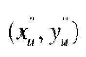
- the acquisition component is configured to acquire direction angles ( ⁇ , ⁇ , ⁇ ) of the distortion lens; and the correction component is configured to perform spatial position changing on a distorted matrix to obtain restored coordinates x u " y u " corresponding to the direction angle ( ⁇ , ⁇ , ⁇ ) of the distortion lens according to the direction angles ( ⁇ , ⁇ , ⁇ ) of the distortion lens and the restored coordinates x u ′ y u ′ .
- the correction component is configured to:
- the device for correction restoration of the distorted image may further include:
- the device for correction restoration of the distorted image may further include an alarming analysis component configured to:
- correction restoration processing is performed on the image acquired by the distortion lens to obtain an undistorted image by adopting the pre-stored distortion parameters of the distortion lens, so that a displayed picture is approximate to a real scene; and moreover, the restored image has the characteristic of large viewing angle, so that blind areas and dead angles of shooting at an ordinary viewing angle are avoided, capturing of an emergency in a security monitoring environment is facilitated, and security alarming accuracy is improved.
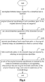
- Fig. 1 shows a flowchart of a method for correction restoration and analysis alarming of the distorted image according to a first embodiment of the disclosure, and as shown in Fig. 1 , the method for correction restoration and analysis alarming of the distorted image in the embodiment includes: Step 10: an original distorted image acquired by a distortion lens is received.
- a monitoring video is acquired through a camera of a fisheye lens (i.e. the distortion lens) and the camera of the fisheye lens is connected with equipment with a distorted image correction restoration device.
- the equipment with the distorted image correction restoration device may be intelligent equipment such as an ordinary computer and a mobile phone, or is dedicated equipment adapted to the fisheye lens, and the camera is directly connected with a monitoring center, or is connected with the monitoring center through the equipment with the distorted image correction restoration device.
- the camera of the fisheye lens transmits shot video data to the computer or the dedicated equipment through a data cable, or transmits the video data to the mobile phone or the monitoring center in a wireless transmission manner, or transmits analyzed data to the monitoring center through the computer, the mobile phone, the dedicated equipment and the like.
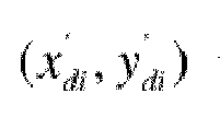
- Step 20 original distorted coordinates x d ′ y d ′ of each coordinate point in the original distorted image are acquired.
- Each coordinate point in the original distorted image may be a position coordinate, and may also be a pixel coordinate.
- the original distorted image may be converted into a grayscale image for correction processing.
- Step 30 pre-stored distortion parameters ( k 1 , k 2 ) of the distortion lens are acquired.
- the distortion parameters of the distortion lens in lens parameters are pre-stored, a distortion degree is higher if absolute values of k 1 and k 2 are greater, and when k 1 and k 2 are both more than 0, it is indicated that four corners of the image are distorted towards the center.
- Step 40 restored coordinates x u ′ y u ′ of each coordinate point in the original distorted image are determined to obtain a restored image.
- the distortion parameters are adopted to restore the original distorted image so as to obtain an undistorted image with a large viewing angle and a corresponding video stream.
- the viewing angle of the corrected image is much larger than a viewing angle of an image obtained by an ordinary lens, so that the problem of blind areas and dead angles of ordinary monitoring may be solved.
- the equipment with the distorted image correction restoration device may also be connected with an alarming system, analysis processing is performed on the restored images to judge whether there is an abnormal emergency in the restored images or not, and if an emergency happens and the number of frames where the emergency is recorded continuously exceeds a certain number, that is, the emergency exists in multi-frame images restored, the emergency is captured, that is, the restored images are recorded, and an alarm notice is synchronously sent to implement automatic alarming.
- correction restoration processing is performed, according to the pre-stored distortion parameters of the distortion lens, on the image acquired by the distortion lens to obtain the undistorted image, so that a displayed picture is approximate to a real scene; and moreover, the restored image has the characteristic of large viewing angle, so that blind areas and dead angles of shooting at an ordinary viewing angle are avoided, capturing of an emergency in a security monitoring environment is facilitated, and security alarming accuracy is improved.
- Fig. 2 shows a flowchart of a method for correction restoration and analysis alarming of the distorted image according to a second embodiment of the disclosure.
- a step that distortion parameters ( k 1 , k 2 ) of the distortion lens are calibrated in the embodiment shown in Fig. 1 is described in the embodiment, wherein the step that the distortion parameters ( k 1 , k 2 ) are calibrated includes: Step 51: a sample image acquired by the distortion lens and a sample image acquired by an ordinary lens are received.
- the sample image is preselected, and calibration characteristics are marked in the sample image.
- calibration characteristics are marked in the sample image.
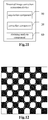
- intersected corners of the checker are marked with solid circles with the same radius, circle center coordinates (x,y,z) calibrated are pre-measured, and circle centers of the solid circles are determined as calibration characteristics of the sample.
- the sample images are shot by the fisheye lens (i.e. the distortion lens) and the ordinary lens respectively.
- the shot sample images shot by the fisheye lens and the ordinary lens respectively are sent to the distorted image correction restoration device.
- Step 52 distorted coordinates ( x d , y d ) of a calibration characteristic in the sample image acquired by the distortion lens and undistorted coordinates ( x u , y u ) of a calibration characteristic in the sample image acquired by the ordinary lens are acquired.
- Identification processing is performed on the calibration characteristics in the sample images acquired by the distortion lens and the ordinary lens. For example, in the checker shown in Fig. 12 , the solid circles in the checker are identified, the circle centers of the solid circles are identified, and coordinate values of the circle centers of the solid circles are determined.
- a table showing the corresponding relationships between sample characteristics is constructed according to a corresponding relationship among practical spatial position coordinates (x,y,z) of a circle center of a sample, distorted coordinates ( x d , y d ) acquired by the distortion lens and undistorted coordinates ( x u , y u ) acquired by the ordinary lens, shown as the following table: Attribute Practical spatial coordinates Undistorted coordinates Distorted coordinates Sequence number x y z x u y u x d y d 1 2 ... N
- projection coordinates of distorted calibration characteristic point are ( x d , y d ).
- the coordinates of the calibration characteristics may be determined in a manner as follows: first, second-order image graying processing is performed on the sample image acquired by the distortion lens and the sample image acquired by the ordinary lens to obtain a distorted sample grayscale image and an ordinary sample grayscale image respectively; then, edge detection is performed on the distorted sample grayscale image and the ordinary sample grayscale image to obtain a distorted sample profile diagram and an ordinary sample profile diagram by adopting an edge detection algorithm respectively; and finally, the calibration characteristics in the distorted sample profile diagram and the ordinary sample profile diagram are detected to obtain the distorted coordinates ( x d , y d ) and the undistorted coordinates ( x u , y u ) by adopting a Hough transform algorithm respectively.
- the number of iteration times may be preset, and iteration may usually be performed for 5 to 6 times. After iteration is performed for many times, the distortion parameters ( k 1 , k 2 ) may be solved, and the obtained distortion parameters are stored in the memory for the lens parameters.
- the distortion parameters of the distortion lens are obtained by adopting the fisheye effect equation, and when the subsequent distorted images are corrected, the image acquired by the distortion lens is restored through the distortion parameters to obtain the undistorted image, so that the displayed picture is approximate to the real scene, capturing of the emergency in the security monitoring environment is facilitated, and security alarming accuracy is improved.
- x di ′ y di ′ are original distorted coordinates after ith iteration
- r i -1 is a radius of the original distorted image after (i-1)th iteration
- each coordinate point in the original distorted image is corrected to determine the restored coordinates by adopting a reverse process of the fisheye effect equation, the image is reconstructed to obtain the restored image according to the restored coordinates, the restored image is undistorted, and the displayed picture is approximate to the real scene, so that capturing of the emergency in the security monitoring environment is facilitated, and security alarming accuracy is improved.
- Fig. 4 is a flowchart of a method for correction restoration and analysis alarming of the distorted image according to a fourth embodiment of the disclosure, and as shown in Fig. 4 , Step 40 in the embodiment, based on the embodiment shown in Fig. 1 , further specifically includes:
- the coordinates obtained after the image is restored may have an angular offset with practical coordinates when the direction angles of the distortion lens with the pre-stored distortion parameters during calibration of the distortion parameters is inconsistent with a direction angle during practical image acquisition, it is necessary to perform spatial position changing on the distorted matrix to obtain the restored coordinates corresponding to the current direction angles to make the obtained restored image more approximate to the real image, so that reality of the displayed picture and emergency capturing accuracy in the security monitoring environment are further improved.
- the coordinates ( x c , y c , z c ) are obtained by a reverse process of perspective transform, and the coordinates are coordinate values before perspective transform, wherein f is an equivalent focal distance of the distortion lens.
- the restored coordinates x u " y u " z u " are mapped into the coordinates ( x c , y c , z c ) before perspective transform after rotation and translation transform, so that the restored coordinates x u " y u " z u " corresponding to the direction angles ( ⁇ , ⁇ , ⁇ ) of the distortion lens may be obtained by the reverse process, wherein k 1 k 2 k 3 k 4 k 5 k 6 k 7 k 8 k 9 is an optical characteristic parameter matrix of the distortion lens, and t x t y t z is a translation vector.
- spatial position changing is performed on the distorted matrix to obtain the restored coordinates corresponding to the current direction angles to make the obtained restored image more approximate to the real image, so that reality of the displayed picture and emergency capturing accuracy in the security monitoring environment are further improved.
- Fig. 6 shows a flowchart of a method for correction restoration and analysis alarming of the distorted image according to a sixth embodiment of the disclosure, and as shown in Fig. 6 , after Step 40, the embodiment, based on the embodiment shown in Fig. 1 , further includes: Step 60: hole coordinate points in the restored image are repaired by adopting an interpolation algorithm.
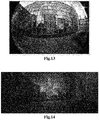
- the holes may exist some black grids, which may be called holes, in the restored image after distortion correction, as shown in Fig. 14 .
- the holes are required to be repaired, and the holes are repaired to restore an undistorted large-viewing-angle image by adopting the interpolation algorithm, as shown in Fig. 15 .
- Step 70 pixels of the original distorted coordinates are restored to the restored coordinates according to a corresponding relationship between original distorted coordinates of the original distorted image and restored coordinates of the restored image.
- a color image is originally obtained during image shooting, the color image is converted into a grayscale image to extract the original distorted coordinates, and it is necessary to perform color restoration to restore the pixels of the original distorted coordinates to the restored coordinates to finally obtain the color-restored image, so that capturing of the emergency in the security monitoring environment is facilitated, and alarming accuracy is further improved.
- Fig. 7 is a flowchart of a method for correction restoration and analysis alarming of the distorted image according to an eighth embodiment of the disclosure.
- a specific analysis alarming step is added in the embodiment, and by the step, the restored image may be analyzed after Step 40 in the embodiment shown in Fig. 1 , and the image subjected to hole repair and color restoration may also be analyzed after Step 70 in the embodiment shown in Fig. 6 .
- the embodiment includes: Step 81: adaptive background learning is performed on multi-frame images restored to obtain a reference background.
- adaptive background learning is performed on multi-frame of images restored and video, and the reference background without any emergency is extracted.
- Adaptive background learning may be reference background extraction over the first n-frame images within a time period. For example, for the images during the first hour, i.e. the images within 0-60 minutes, adaptive learning is performed on the images during the first 0-5 minutes to extract the reference background, then the reference background is compared with the images during the 6th-60th minutes; and for the images during the second hour, i.e. the images within 60-120 minutes, adaptive learning is performed on the images during 60th-65th minutes to extract the reference background, then the reference background is compared with the images during the 66th-120th minutes, and so on.
- Step 82 segmentation processing is performed on the subsequent restored images according to the reference background by adopting an image segmentation algorithm, and a different target characteristic is extracted.
- a background image the same as or similar to the reference background and a foreground image greatly different from the reference background are segmented by adopting the image segmentation algorithm, and the different target characteristic is extracted from the foreground image. For example, there is one more person in a certain subsequent image compared with the reference background, and an image of the person is determined as a different target characteristic; and for another example, there is a box in the reference background, there is no box in a certain subsequent image, and then a position where the box is placed is determined as a different target characteristic.
- Step 83 filtering processing is performed on the different target characteristic to exclude the restored image of which the different target characteristic is within a filtering range.
- the filtering range is preset to filter the different target characteristic caused by noise to exclude the image which is differentiated by noise.
- Step 84 motion matching tracking of the different target characteristic is performed on the subsequent restored images by adopting the different target characteristic out of the filtering range.
- the subsequent images are matched and tracked to judge whether the different target characteristic still exists in the subsequent images or not.
- an image of a person appears on a right side of the ith-frame image
- motion matching tracking is performed on the image of the person in each image within a certain time period, and the image of the person gradually moves leftwards.
- there is a box in middle of the first to (i-1)th-frame image there is no box in the ith-frame image, there is no box all the time in each image within a certain time period, or a position of the box changes in the ith-frame image, and the box continuously moves in each image within the time period.
- Step 85 when the number of the restored images with the different target characteristic exceeds a preset frame number, the restored images are recorded as images with a sudden change, and an alarm is given.
- an image of the person may not exist for a long time in a video picture, and may fast move out of the picture within a specified time length.
- the number of frames within 2 seconds is determined as the preset frame number if the image of the person exists in the video picture for 2 seconds when the person passes by. It is determined as a normal condition and alarming is not required if the image of the person appears within the preset frame number, and if the image of the person continuously appears out of a range of the preset frame number, it is indicated that the person appears for long in a monitoring area, there may be an abnormity and alarming is required.
- a box suddenly disappears from the monitoring range, if the box reappears in the image after 0.5 second, accidental interference is determined and alarming is not required, and if the box does not appear for more than 5 seconds, it may be considered as an abnormity, and an alarm notice is required to be sent to implement automatic alarming.
- an intelligent analysis alarming object is the corrected and restored image of the distorted image acquired by the fisheye lens, and the obtained image has the characteristic of large viewing angle compared with the image acquired by the ordinary lens, so that the problem of blind areas and dead angles of ordinary monitoring may be solved, capturing of the emergency in the security monitoring environment is facilitated, and security alarming accuracy is improved.
- Fig. 8 is a structure diagram of a device for correction restoration and analysis alarming of the distorted image according to a first embodiment of the disclosure, and as shown in Fig. 8 , the device for correction restoration and analysis alarming of the distorted image in the embodiment includes:
- a monitoring video is acquired through a camera of a fisheye lens (i.e. the distortion lens), and the camera of the fisheye lens is connected with equipment with a distorted image correction restoration device.
- the equipment with the distorted image correction restoration device may be intelligent equipment such as an ordinary computer and a mobile phone, or is dedicated equipment adapted to the fisheye lens, and the camera is directly connected with a monitoring center, or is connected with the monitoring center through the equipment with the distorted image correction restoration device.
- the camera of the fisheye lens transmits shot video data to the computer or the dedicated equipment through a data cable, or transmits the video data to the mobile phone or the monitoring center in a wireless transmission manner, or transmits analyzed data to the monitoring center through the computer, the mobile phone, the dedicated equipment and the like.
- Each coordinate point in the original distorted image may be a position coordinate, and may also be a pixel coordinate. When the coordinates are acquired, the original distorted image may be converted into a grayscale image for correction processing.
- the distortion parameters of the distortion lens are pre-stored in the memory for the lens parameters, a distortion degree is higher if absolute values of k 1 and k 2 are greater, and when k 1 and k 2 are both more than 0, it is indicated that four corners of the image are distorted towards the center.
- the distortion parameters are adopted to restore the original distorted image so as to obtain an undistorted image with a large viewing angle and a corresponding video stream.
- the viewing angle of the corrected image is much larger than a viewing angle of an image obtained by an ordinary lens, so that the problem of blind areas and dead angles of ordinary monitoring may be solved.
- the equipment with the distorted image correction restoration device may also be connected with an alarming system, analysis processing is performed on the restored images to judge whether there is an abnormal emergency in the restored images or not, and if an emergency happens and the number of frames where the emergency is recorded continuously exceeds a certain number, that is, the emergency exists in multi-frame images restored, the emergency is captured, that is, the restored images are recorded, and an alarm notice is synchronously sent to implement automatic alarming.
- correction restoration processing is performed, according to the pre-stored distortion parameters of the distortion lens, on the image acquired by the distortion lens to obtain the undistorted image, so that a displayed picture is approximate to a real scene; and moreover, the restored image has the characteristic of large viewing angle, so that blind areas and dead angles of shooting at an ordinary viewing angle are avoided, capturing of an emergency in a security monitoring environment is facilitated, and security alarming accuracy is improved.
- Fig. 9 shows a structurediagram of a device for correction restoration and analysis alarming of the distorted image according to a second embodiment of the disclosure.
- a parameter calibration component 30 is added in the embodiment based on the embodiment shown in Fig. 8 , and is configured to:
- the parameter calibration component 30 is further configured to:
- the sample image is preselected, and calibration characteristics are marked in the sample image.
- calibration characteristics are marked in the sample image.
- intersected corners of the checker are marked with solid circles with the same radius, circle center coordinates (x,y,z) calibrated are pre-measured, and circle centers of the solid circles are determined as calibration characteristics of the sample.
- the sample images are shot by the fisheye lens (i.e. the distortion lens) and the ordinary lens respectively.
- the fisheye lens and the ordinary lens send the shot sample images to the distorted image correction restoration device.
- Identification processing is performed on the calibration characteristics in the sample images acquired by the distortion lens and the ordinary lens. For example, in the checker shown in Fig. 12 , the solid circles in the checker are identified, the circle centers of the solid circles are identified, and coordinate values of the circle centers of the solid circles are determined.
- a table showing corresponding a relationship between sample characteristics is constructed according to a corresponding relationship among practical spatial position coordinates (x,y,z) of a circle center of a sample, distorted coordinates ( x d , y d ) acquired by the distortion lens and undistorted coordinates ( x u , y u ) acquired by the ordinary lens, shown as the following table: Attribute Practical spatial coordinates Undistorted coordinates Distorted coordinates Sequence number x y z X u y u x d y d 1 2 ... N
- projection coordinates of a distorted calibration characteristic point are ( x d , y d ) .
- the distortion parameters ( k 1 , k 2 ) are calculated by adopting the fisheye effect equation, the image shot by the distortion lens is shown in Fig. 13 , the number of iteration times may be preset, and iteration may usually be performed for 5 to 6 times. After iteration is performed for many times, the distortion parameters ( k 1 , k 2 ) may be solved, and the obtained distortion parameters are stored in the memory for the lens parameters.
- the distortion parameters of the distortion lens are obtained by adopting the fisheye effect equation, and when the distorted image is subsequently corrected, the image acquired by the distortion lens is restored through the distortion parameters to obtain the undistorted image, so that the displayed picture is approximate to the real scene, capturing of the emergency in the security monitoring environment is facilitated, and security alarming accuracy is improved.
- each coordinate point in the original distorted image is corrected to determine the restored coordinates by adopting a reverse process of the fisheye effect equation, the image is reconstructed to obtain the restored image according to the restored coordinates, the restored image is undistorted, and the displayed picture is approximate to the real scene, so that capturing of the emergency in the security monitoring environment is facilitated, and security alarming accuracy is improved.
- the acquisition component 10 is further configured to acquire direction angles ( ⁇ , ⁇ , ⁇ ) of the distortion lens; and the correction component 20 is further configured to perform spatial position changing on a distorted matrix to obtain restored coordinates x u " y u " corresponding to the direction angles ( ⁇ , ⁇ , ⁇ ) of the distortion lens according to the direction angles ( ⁇ , ⁇ , ⁇ ) of the distortion lens and the restored coordinates x u ′ y u ′ .
- the coordinates obtained after the image is restored may have an angular offset with practical coordinates when the direction angle of the distortion lens with the pre-stored distortion parameter during calibration of the distortion parameter is inconsistent with a direction angle during practical image acquisition, it is necessary to perform spatial position changing on the distorted matrix to obtain the restored coordinates corresponding to the current direction angle to make the obtained restored image more approximate to the real image, so that reality of the displayed picture and emergency capturing accuracy in the security monitoring environment are further improved.
- the correction component 20 is further configured to:
- the coordinates ( x c , y c , z c ) are obtained by a reverse process of perspective transform, and the coordinates are coordinate values before perspective transform.
- restored coordinates x u " y u " z u " are mapped into the coordinates ( x c , y c , z c ) before perspective transform after rotation and translation transform, so that the restored coordinates x u " y u " z u " corresponding to the direction angles ( ⁇ , ⁇ , ⁇ ) of the distortion lens may be obtained by the reverse process.
- spatial position changing is performed on the distorted matrix to obtain the restored coordinates corresponding to the current direction angles to make the obtained restored image more approximate to the real image, so that reality of the displayed picture and emergency capturing accuracy in the security monitoring environment are further improved.
- Fig. 10 is a structure diagram of a device for correction restoration and analysis alarming of the distorted image according to a second embodiment of the disclosure. As shown in Fig. 10 , the following components are added in the embodiment based on the embodiment shown in Fig. 8 :
- the holes may exist some black grids, which may be called holes, in the restored image after distortion correction, as shown in Fig. 14 .
- the holes are required to be repaired, and the holes are repaired to restore an undistorted large-viewing-angle image by adopting the interpolation algorithm, as shown in Fig. 15 .
- a color image is originally obtained during image shooting, the color image is converted into a grayscale image to extract the original distorted coordinates, and it is necessary to perform color restoration to restore the pixels of the original distorted coordinates to the restored coordinates to finally obtain the color-restored image, so that capturing of the emergency in the security monitoring environment is facilitated, and alarming accuracy is further improved.
- Fig. 11 shows a structure diagram of a device for correction restoration and analysis alarming of the distorted image according to a third embodiment of the disclosure, and as shown in Fig. 11 , an alarming analysis component 60 is added in the embodiment based on the embodiment shown in Fig. 8 , and is configured to:
- adaptive background learning is performed on multi-frame image restored and video, and the reference background without any emergency is extracted.
- Adaptive background learning may be reference background extraction over the first n-frame images within a time period. For example, for the images during the first hour, i.e. the images within 0-60 minutes, adaptive learning is performed on the images during the first 0-5 minutes to extract the reference background, then the reference background is compared with the images during the 6th-60th minutes; for the images during the second hour, i.e. 60-120 minutes, adaptive learning is performed on the image during 60th-65th minutes to extract the reference background, then the reference background is compared with the images during the 66th-120th minutes, and so on.
- a background image the same as or similar to the reference background and a foreground image greatly different from the reference background are segmented by adopting the image segmentation algorithm, and the different target characteristic is extracted from the foreground image. For example, there is one more person in a certain subsequent image compared with the reference background, and an image of the person is determined as a different target characteristic; and for another example, there is a box in the reference background, there is no box in a certain subsequent image, and then a position where the box is placed is determined as a different target characteristic.
- the filtering range is preset to filter the different target characteristic caused by noise to exclude the image which is differentiated by noise.
- the different target characteristic out of the filtering range it may be an emergency, and the subsequent image is matched and tracked to judge whether the different target characteristic still exists in the subsequent image or not. For example, an image of a person appears on a right side of the ith-frame image, motion matching tracking is performed on the image of the person in each image within a certain time period, and the image of the person gradually moves leftwards.
- an image of the person may not exist for a long time in a video picture, and may fast move out of the picture within a specified time length, the number of frames within 2 seconds is determined as the preset frame number if the image of the person exists in the video picture for 2 seconds when the person passes by, it is determined as a normal condition and alarming is not required if the image of the person appears within the preset frame number, and if the image of the person continuously appears out of a range of the preset frame number, it is indicated that the person appears for long in a monitoring area, there may be an abnormity and alarming is required.
- a box suddenly disappears from the monitoring range, if the box reappears in the image after 0.5 second, accidental interference is determined and alarming is not required, and if the box does not appear for more than 5 seconds, it may be considered as an abnormity, and an alarm notice is required to be sent to implement automatic alarming.
- an intelligent analysis alarming object is the corrected and restored image of the distorted image acquired by the fisheye lens, and the image has the characteristic of large viewing angle compared with the image acquired by the ordinary lens, so that the problem of blind areas and dead angles of ordinary monitoring may be solved, capturing of the emergency in the security monitoring environment is facilitated, and security alarming accuracy is improved.
- the method for correction restoration and analysis alarming of the distorted image and device have the following beneficial effects: according to the embodiment, the intelligent analysis alarming object is the corrected and restored image of the distorted image acquired by the fisheye lens, and the image has the characteristic of large viewing angle compared with the image acquired by the ordinary lens, so that the problem of blind areas and dead angles of ordinary monitoring may be solved, capturing of the emergency in the security monitoring environment is facilitated, and security alarming accuracy is improved.
Landscapes
- Engineering & Computer Science (AREA)
- Physics & Mathematics (AREA)
- General Physics & Mathematics (AREA)
- Theoretical Computer Science (AREA)
- Multimedia (AREA)
- Image Processing (AREA)
- Geometry (AREA)
Claims (12)
- Verfahren zur Korrekturwiederherstellung eines verzerrten Bildes, umfassend:Empfangen eines von einer Verzerrungslinse (S10) erfassten ursprünglichen verzerrten Bildes und Erfassen von ursprünglichen verzerrten Koordinaten
 Erfassen vorgespeicherter Verzerrungsparameter (k 1, k 2) der Verzerrungslinse (S30) und Bestimmen wiederhergestellter Koordinaten
 Erfassen von Richtungswinkeln (α,β,γ) der Verzerrungslinse (S43); undDurchführen einer räumlichen Positionsänderung auf einer verzerrten Matrix, um wiederhergestellte Koordinaten
 wobei das Durchführen der räumlichen Positionsänderung auf der verzerrten Matrix, um wiederhergestellte Koordinaten
 Einsetzen der wiederhergestellten Koordinaten
 Einsetzen der Richtungswinkel (α,β,γ) und der Linsenkoordinaten (x c ,y c, zc ) der Verzerrungslinse in Formel:


- Verfahren zur Korrekturwiederherstellung des verzerrten Bildes nach Anspruch 1, wobei das Kalibrieren der Verzerrungsparameter (k 1,k 2) der Verzerrungslinse umfasst:Empfangen eines von der Verzerrungslinse erfassten Probenbildes und eines von einer gewöhnlichen Linse erfassten Probenbildes (S51);Erfassen verzerrter Koordinaten (xd,yd ) einer Kalibrierungscharakteristik in dem von der Verzerrungslinse erfassten Probenbild und unverzerrter Koordinaten (xu ,yu ) einer Kalibrierungscharakteristik in dem von der gewöhnlichen Linse erfassten Probenbild (S52); undEinsetzen der verzerrten Koordinaten (xd,yd ) und der unverzerrten Koordinaten (xu ,yu ) in Formel:


- Verfahren zur Korrekturwiederherstellung des verzerrten Bildes nach Anspruch 2, wobei das Erfassen der verzerrten Koordinaten (xd ,yd ) der Kalibrierungscharakteristik in dem von der Verzerrungslinse erfassten Probenbild und der unverzerrten Koordinaten (xd ,yd ) der Kalibrierungscharakteristik in dem von der gewöhnlichen Linse erfassten Probenbild umfasst:Durchführen einer Bildvergrauungsverarbeitung zweiter Ordnung mit dem von der Verzerrungslinse erfassten Probenbild und dem von der gewöhnlichen Linse erfassten Probenbild, um ein verzerrtes Probengraustufenbild bzw. ein gewöhnliches Probengraustufenbild zu erhalten;Durchführen einer Kantenerkennung mit dem verzerrten Probengraustufenbild und dem gewöhnlichen Probengraustufenbild, um ein Profildiagramm der verzerrten Probe und ein Profildiagramm der gewöhnlichen Probe zu erhalten, indem jeweils ein Kantenerkennungsalgorithmus angewendet wird; undErfassen der Kalibrierungscharakteristiken in dem Profildiagramm der verzerrten Probe und in dem Profildiagramm der gewöhnlichen Probe, um die verzerrten Koordinaten (xd ,yd ) bzw. die unverzerrten Koordinaten (xu,yu ) durch Anwenden eines Hough-Transformationsalgorithmus zu erhalten.
- Verfahren zur Korrekturwiederherstellung des verzerrten Bildes nach Anspruch 1, wobei das Bestimmen der wiederhergestellten Koordinaten (xu ,yu ) jedes Koordinatenpunkts in dem ursprünglichen verzerrten Bild umfasst (S40):
Einsetzen der ursprünglichen verzerrten Koordinaten (xd ,yd ) und der Verzerrungsparameter (k 1,k 2) in Formel: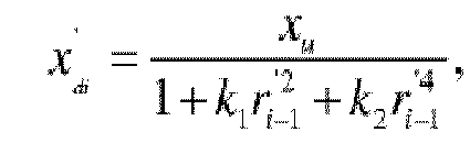




- Verfahren zur Korrekturwiederherstellung des verzerrten Bildes nach Anspruch 1, wobei nach Erfassen der vorgespeicherten Verzerrungsparametern (k 1,k 2) der Verzerrungslinse und Bestimmen der wiederhergestellten Koordinaten
 Reparieren von Lochkoordinatenpunkten in dem wiederhergestellten Bild durch Anwenden eines Interpolationsalgorithmus (S60); undWiederherstellen von Pixeln der ursprünglichen verzerrten Koordinaten zu den wiederhergestellten Koordinaten gemäß entsprechenden Beziehungen zwischen den ursprünglichen verzerrten Koordinaten des ursprünglichen verzerrten Bildes und den wiederhergestellten Koordinaten des wiederhergestellten Bildes (S70).
 - Verfahren zur Korrekturwiederherstellung des verzerrten Bildes nach einem der Ansprüche 1 bis 5, wobei nach Erfassen der vorgespeicherten Verzerrungsparametern (k 1 ,k 2) der Verzerrungslinse und Bestimmen der wiederhergestellten Koordinaten
 Durchführen eines adaptiven Hintergrundlernens an Bildern mit mehreren Einzelbildern, die wiederhergestellt wurden, um einen Referenzhintergrund zu erhalten (S81);Durchführen einer Segmentierungsverarbeitung für nachfolgende wiederhergestellte Bilder gemäß dem Referenzhintergrund durch Anwenden eines Bildsegmentierungsalgorithmus und Extrahieren einer unterschiedlichen Zielcharakteristik zwischen segmentierten nachfolgenden wiederhergestellten Bildern und dem Referenzhintergrund (S82);Durchführen einer Filterverarbeitung für die unterschiedliche Zielcharakteristik gemäß einem Filterbereich, der voreingestellt ist, um ein wiederhergestelltes Bild auszuschließen, dessen unterschiedliche Zielcharakteristik innerhalb des Filterbereichs liegt (S83);Durchführen einer Bewegungsanpassungsverfolgung der unterschiedlichen Zielcharakteristik für die nachfolgenden wiederhergestellten Bildern durch Übernehmen der unterschiedlichen Zielcharakteristik außerhalb des Filterbereichs (S84); undwenn die Anzahl der wiederhergestellten Bilder mit der unterschiedlichen Zielcharakteristik eine voreingestellte Einzelbildnummer überschreitet, Aufzeichnen der wiederhergestellten Bilder als Bilder mit einer plötzlichen Änderung und Ausgeben eines Alarms (S85).
 - Vorrichtung zur Korrekturwiederherstellung eines verzerrten Bildes, umfassend:eine Erfassungskomponente (10), die konfiguriert ist zum Empfangen eines ursprünglichen verzerrten Bilds, das von einer Verzerrungslinse erfasst wurde, Erfassen ursprünglicher verzerrter Koordinaten
 eine Korrekturkomponente (20), die konfiguriert ist zum Erfassen vorgespeicherter Verzerrungsparameter (k 1,k 2) der Verzerrungslinse, Bestimmen wiederhergestellter Koordinaten

 wobei die Korrekturkomponente (20) ferner konfiguriert ist zumEinsetzen der wiederhergestellten Koordinaten
 Einsetzen der Richtungswinkel (α,β,γ) und der Linsenkoordinaten (xc ,yc ,zc ) der Verzerrungslinse in Formel:


- Vorrichtung zur Korrekturwiederherstellung des verzerrten Bildes nach Anspruch 7, ferner umfassend eine Parameterkalibrierungskomponente (30), die konfiguriert ist zum
Empfangen eines von der Verzerrungslinse erfassten Probenbildes und eines von einer gewöhnlichen Linse erfassten Probenbildes;
Erfassen verzerrter Koordinaten (xd,yd ) einer Kalibrierungscharakteristik in dem von der Verzerrungslinse erfassten Probenbild und unverzerrter Koordinaten (x u, yu ) einer Kalibrierungscharakteristik in dem von der gewöhnlichen Linse erfassten Probenbild; und
Einsetzen der verzerrten Koordinaten (xd,yd ) und der unverzerrten Koordinaten (xu,yu ) in Formel:


- Vorrichtung zur Korrekturwiederherstellung des verzerrten Bildes nach Anspruch 8, wobei die Parameterkalibrierungskomponente (30) ferner konfiguriert ist zum:Durchführen einer Bildvergrauungsverarbeitung zweiter Ordnung mit dem von der Verzerrungslinse erfassten Probenbild und dem von der gewöhnlichen Linse erfassten Probenbild, um ein verzerrtes Probengraustufenbild bzw. ein gewöhnliches Probengraustufenbild zu erhalten;Durchführen einer Kantenerkennung mit dem verzerrten Probengraustufenbild und dem gewöhnlichen Probengraustufenbild, um ein verzerrtes Probenprofildiagramm und ein gewöhnliches Probenprofildiagramm zu erhalten, indem jeweils ein Kantenerkennungsalgorithmus angewendet wird; undErfassen der Kalibrierungscharakteristiken in dem Profildiagramm der verzerrten Probe und in dem Profildiagramm der normalen Probe, um die verzerrten Koordinaten (x d, yd ) bzw. die unverzerrten Koordinaten (xd,yd ) durch Anwenden eines Hough-Transformationsalgorithmus zu erhalten.
- Vorrichtung zur Korrekturwiederherstellung des verzerrten Bildes nach Anspruch 7, wobei die Korrekturkomponente (20) ferner konfiguriert ist zum:
Einsetzen der ursprünglichen verzerrten Koordinaten


- Vorrichtung zur Korrekturwiederherstellung des verzerrten Bildes nach Anspruch 7, ferner umfassend:eine Reparaturkomponente (40), die konfiguriert ist zum Reparieren von Lochkoordinatenpunkten in dem wiederhergestellten Bild durch Anwenden eines Interpolationsalgorithmus; undeine Pixelwiederherstellungskomponente (50), die konfiguriert ist zum Wiederherstellen von Pixeln der ursprünglichen verzerrten Koordinaten zu den wiederhergestellten Koordinaten gemäß entsprechenden Beziehungen zwischen den ursprünglichen verzerrten Koordinaten des ursprünglichen verzerrten Bildes und den wiederhergestellten Koordinaten des wiederhergestellten Bildes.
- Vorrichtung zur Korrekturwiederherstellung des verzerrten Bildes nach einem der Ansprüche 7 bis 11, ferner umfassend eine Alarmanalysekomponente (60), die konfiguriert ist zum
Durchführen eines adaptiven Hintergrundlernens an Bildern mit mehreren Einzelbildern, die wiederhergestellt wurden, um einen Referenzhintergrund zu erhalten;
Durchführen einer Segmentierungsverarbeitung für nachfolgende wiederhergestellte Bilder gemäß dem Referenzhintergrund durch Anwenden eines Bildsegmentierungsalgorithmus und Extrahieren einer unterschiedlichen Zielcharakteristik;
Durchführen einer Filterverarbeitung für die unterschiedliche Zielcharakteristik gemäß einem Filterbereich, der voreingestellt ist, um ein wiederhergestelltes Bild auszuschließen, dessen unterschiedliche Zielcharakteristik innerhalb des Filterbereichs liegt;
Durchführen einer Bewegungsanpassungsverfolgung der unterschiedlichen Zielcharakteristik für die nachfolgenden wiederhergestellten Bildern durch Übernehmen der unterschiedlichen Zielcharakteristik außerhalb des Filterbereichs; und
wenn die Anzahl der wiederhergestellten Bilder mit der unterschiedlichen Zielcharakteristik eine voreingestellte Einzelbildnummer überschreitet, Aufzeichnen der wiederhergestellten Bilder als Bilder mit einer plötzlichen Änderung und Ausgeben eines Alarms.
Applications Claiming Priority (2)
| Application Number | Priority Date | Filing Date | Title |
|---|---|---|---|
| CN201310598077.9A CN104657940B (zh) | 2013-11-22 | 2013-11-22 | 畸变图像校正复原与分析报警的方法和装置 |
| PCT/CN2014/075372 WO2014176971A1 (zh) | 2013-11-22 | 2014-04-15 | 畸变图像校正复原与分析报警的方法和装置 |
Publications (3)
| Publication Number | Publication Date |
|---|---|
| EP3073440A1 EP3073440A1 (de) | 2016-09-28 |
| EP3073440A4 EP3073440A4 (de) | 2016-11-30 |
| EP3073440B1 true EP3073440B1 (de) | 2020-08-12 |
Family
ID=51843108
Family Applications (1)
| Application Number | Title | Priority Date | Filing Date |
|---|---|---|---|
| EP14791339.6A Not-in-force EP3073440B1 (de) | 2013-11-22 | 2014-04-15 | Verfahren und vorrichtung zur wiederherstellungskorrektur und alarmanalyse eines verzerrten bildes |
Country Status (4)
| Country | Link |
|---|---|
| US (1) | US10304169B2 (de) |
| EP (1) | EP3073440B1 (de) |
| CN (1) | CN104657940B (de) |
| WO (1) | WO2014176971A1 (de) |
Families Citing this family (24)
| Publication number | Priority date | Publication date | Assignee | Title |
|---|---|---|---|---|
| CN104794189B (zh) * | 2015-04-16 | 2018-05-08 | 惠州Tcl移动通信有限公司 | 一种图像筛选方法及筛选系统 |
| CN105120229A (zh) * | 2015-09-16 | 2015-12-02 | 温州大学 | 广角镜头全方位监控器及图像匹配的方法 |
| CN105227948B (zh) * | 2015-09-18 | 2017-10-27 | 广东欧珀移动通信有限公司 | 一种查找图像中畸变区域的方法及装置 |
| CN107154027B (zh) * | 2017-04-17 | 2020-07-07 | 深圳大学 | 一种畸变图像复原的补偿方法及装置 |
| CN107317953B (zh) * | 2017-06-30 | 2020-09-01 | 上海兆芯集成电路有限公司 | 图像获取方法及其装置 |
| CN107333028B (zh) * | 2017-06-30 | 2020-08-25 | 上海兆芯集成电路有限公司 | 图像获取方法及其装置 |
| CN107707911B (zh) * | 2017-10-27 | 2019-05-28 | 信利光电股份有限公司 | 一种测试图片的生成方法 |
| CN109949230A (zh) * | 2017-12-20 | 2019-06-28 | 艾迪普(北京)文化科技股份有限公司 | 基于图像识别的广角摄像机畸变渲染方法 |
| CN108426702B (zh) * | 2018-01-19 | 2020-06-02 | 华勤通讯技术有限公司 | 增强现实设备的色散测量装置及方法 |
| CN108694701A (zh) * | 2018-03-21 | 2018-10-23 | 南京睿悦信息技术有限公司 | 用于离轴曲面反射式光学系统反畸变算法 |
| US10936885B2 (en) | 2018-05-15 | 2021-03-02 | Toyota Research Institute, Inc. | Systems and methods of processing an image |
| CN111656391B (zh) * | 2018-07-17 | 2023-09-22 | 华为技术有限公司 | 一种图像校正方法和终端 |
| CN109167784A (zh) * | 2018-08-31 | 2019-01-08 | 篱笆墙网络科技有限公司 | 区块链上数据处理方法及系统 |
| CN111862145B (zh) * | 2019-04-24 | 2022-05-17 | 四川大学 | 一种基于多尺度行人检测的目标跟踪方法 |
| CN110149511B (zh) * | 2019-05-13 | 2023-05-12 | 北京理工大学 | 一种畸变校正方法、装置及显示系统 |
| CN111950328A (zh) * | 2019-05-15 | 2020-11-17 | 阿里巴巴集团控股有限公司 | 确定图片中目标物类别的方法及装置 |
| CN110390339B (zh) * | 2019-07-16 | 2021-11-19 | 北京市计算中心有限公司 | 一种图像校正方法、装置及存储介质 |
| CN111612720B (zh) * | 2020-05-21 | 2023-11-07 | 烟台艾睿光电科技有限公司 | 一种广角红外图像优化方法、系统及相关组件 |
| CN114972046A (zh) * | 2021-02-23 | 2022-08-30 | 武汉Tcl集团工业研究院有限公司 | 视频稳化方法、装置、终端设备及计算机可读存储介质 |
| CN113570518B (zh) * | 2021-07-22 | 2023-11-14 | 上海明略人工智能(集团)有限公司 | 一种图像矫正方法、系统、计算机设备和存储介质 |
| US12148132B2 (en) * | 2022-01-27 | 2024-11-19 | Altek Semiconductor Corporation | Image calibration method and image calibration apparatus |
| CN117372797A (zh) * | 2022-06-30 | 2024-01-09 | 北京小米移动软件有限公司 | 模型训练方法、图像处理方法、装置、电子设备及介质 |
| CN115393793A (zh) * | 2022-08-15 | 2022-11-25 | 中国民航机场建设集团有限公司 | 强夯作业区安全隐患监测方法、系统、设备及存储介质 |
| CN116312420A (zh) * | 2022-10-24 | 2023-06-23 | 中航洛阳光电技术有限公司 | 一种基于rgb的自适应平移平显画面的方法及系统 |
Family Cites Families (18)
| Publication number | Priority date | Publication date | Assignee | Title |
|---|---|---|---|---|
| US6670965B1 (en) * | 2000-09-29 | 2003-12-30 | Intel Corporation | Single-pass warping engine |
| EP2533192B1 (de) * | 2003-07-28 | 2017-06-28 | Olympus Corporation | Bildverarbeitungsvorrichtung, Bildverarbeitungsverfahren und Verfahren zur Berichtigung von Verzerrungen |
| US20080101713A1 (en) * | 2006-10-27 | 2008-05-01 | Edgar Albert D | System and method of fisheye image planar projection |
| TWI441514B (zh) * | 2008-11-12 | 2014-06-11 | Avisonic Technology Corp | 魚眼影像校正及減輕透視變形的影像處理方法及相關影像處理裝置 |
| US8446433B1 (en) * | 2009-06-12 | 2013-05-21 | Lucasfilm Entertainment Company Ltd. | Interactive visual distortion processing |
| CN101625760A (zh) * | 2009-07-28 | 2010-01-13 | 谭洪舟 | 一种证件图像倾斜校正的办法 |
| CN101650830B (zh) | 2009-08-06 | 2012-08-15 | 中国科学院声学研究所 | 一种压缩域视频镜头突变与渐变联合自动分割方法 |
| CN102194241B (zh) * | 2011-04-28 | 2013-07-10 | 西安交通大学 | 基于互联网的艺术拼图系统设计方法 |
| US9105090B2 (en) * | 2011-07-13 | 2015-08-11 | Analog Devices, Inc. | Wide-angle lens image correction |
| CN102306292A (zh) * | 2011-08-01 | 2012-01-04 | 青岛海信网络科技股份有限公司 | 一种复合式倾斜校正方法 |
| US20130128050A1 (en) | 2011-11-22 | 2013-05-23 | Farzin Aghdasi | Geographic map based control |
| JP5832341B2 (ja) * | 2012-03-09 | 2015-12-16 | 株式会社トプコン | 動画処理装置、動画処理方法および動画処理用のプログラム |
| CN102663734A (zh) * | 2012-03-15 | 2012-09-12 | 天津理工大学 | 鱼眼镜头的标定及鱼眼图像的畸变矫正方法 |
| CN102902945B (zh) * | 2012-09-28 | 2015-04-15 | 南京汇兴博业数字设备有限公司 | 基于快速响应矩阵码外轮廓的畸变校正方法 |
| CN103107121B (zh) * | 2013-01-30 | 2015-04-22 | 福建省威诺数控有限公司 | 一种基于视觉的晶圆角度偏差自动校正方法 |
| CN103226814B (zh) * | 2013-04-02 | 2015-09-30 | 湖南大学 | 一种基于医药视觉检测机器人图像校正的药瓶异物检测方法 |
| CN103279924B (zh) * | 2013-05-24 | 2015-11-25 | 中南大学 | 一种对任意倾斜角度的专利证书图像的校正方法 |
| JP5846268B1 (ja) * | 2014-08-12 | 2016-01-20 | 株式会社リコー | 画像処理システム、画像処理装置、プログラムおよび撮像システム |
-
2013
- 2013-11-22 CN CN201310598077.9A patent/CN104657940B/zh not_active Expired - Fee Related
-
2014
- 2014-04-15 WO PCT/CN2014/075372 patent/WO2014176971A1/zh not_active Ceased
- 2014-04-15 US US15/038,521 patent/US10304169B2/en not_active Expired - Fee Related
- 2014-04-15 EP EP14791339.6A patent/EP3073440B1/de not_active Not-in-force
Non-Patent Citations (1)
| Title |
|---|
| None * |
Also Published As
| Publication number | Publication date |
|---|---|
| WO2014176971A1 (zh) | 2014-11-06 |
| CN104657940A (zh) | 2015-05-27 |
| EP3073440A4 (de) | 2016-11-30 |
| US20160300334A1 (en) | 2016-10-13 |
| US10304169B2 (en) | 2019-05-28 |
| EP3073440A1 (de) | 2016-09-28 |
| CN104657940B (zh) | 2019-03-15 |
Similar Documents
| Publication | Publication Date | Title |
|---|---|---|
| US10304169B2 (en) | Method and device for correction restoration and analysis alarming of distorted image | |
| EP3588004B1 (de) | Stereoskopische kamera und höhenerfassungsverfahren dafür sowie höhenerfassungssystem | |
| JP7140580B2 (ja) | ステレオ撮像装置 | |
| US7961953B2 (en) | Image monitoring system | |
| CN114399882A (zh) | 一种用于消防机器人的火源探测识别并预警方法 | |
| US10902553B2 (en) | Method and apparatus for generating an enhanced digital image of a physical object or environment | |
| EP3205084B1 (de) | Bildverarbeitungsverfahren | |
| DE102010001520A1 (de) | Durch einen Flugzeugsensor unterstütztes Iriserfassungssystem und -Verfahren | |
| US10931901B2 (en) | Method and apparatus for selectively correcting fixed pattern noise based on pixel difference values of infrared images | |
| CN104519328A (zh) | 图像处理设备、图像捕捉装置和图像处理方法 | |
| CN109559353B (zh) | 摄像模组标定方法、装置、电子设备及计算机可读存储介质 | |
| DE102022128919A1 (de) | Informationsverarbeitungsvorrichtung, informationsverarbeitungssystem, informationsverarbeitungsverfahren und aufzeichnungsmedium | |
| CN118379230B (zh) | 一种汽车dms摄像头的图像质量优化系统 | |
| US20150373286A1 (en) | Imaging device and infrared image generation method | |
| US8620069B1 (en) | Automatic triangle orientation detection algrorithm | |
| CN118018862A (zh) | 基于微光夜视产品的降低传输延时的方法 | |
| CN121032945A (zh) | 基于机器学习的oled显示屏画面缺陷检测方法 | |
| CN105469413B (zh) | 一种基于归一化振铃加权的无参考模糊复原图像综合质量评估方法 | |
| KR101602293B1 (ko) | 영상 처리를 통한 해안선 측정 방법 및 장치 | |
| KR20140038749A (ko) | 영상 왜곡 보정 장치 및 방법 | |
| JP6799325B2 (ja) | 画像補正装置、画像補正方法、注目点認識装置、注目点認識方法及び異常検知システム | |
| CN112949390B (zh) | 一种基于视频质量的事件检测方法、装置 | |
| KR20150021352A (ko) | 영상 정합 장치 및 이를 이용한 영상 정합 방법 | |
| CN112529956B (zh) | 黑体位置检测方法、电子装置以及计算机可读存储介质 | |
| CN115567678B (zh) | 一种高空抛物监测方法及其系统 |
Legal Events
| Date | Code | Title | Description |
|---|---|---|---|
| PUAI | Public reference made under article 153(3) epc to a published international application that has entered the european phase |
Free format text: ORIGINAL CODE: 0009012 |
|
| 17P | Request for examination filed |
Effective date: 20160525 |
|
| AK | Designated contracting states |
Kind code of ref document: A1 Designated state(s): AL AT BE BG CH CY CZ DE DK EE ES FI FR GB GR HR HU IE IS IT LI LT LU LV MC MK MT NL NO PL PT RO RS SE SI SK SM TR |
|
| AX | Request for extension of the european patent |
Extension state: BA ME |
|
| A4 | Supplementary search report drawn up and despatched |
Effective date: 20161027 |
|
| RIC1 | Information provided on ipc code assigned before grant |
Ipc: G06T 5/00 20060101AFI20161021BHEP Ipc: G06T 3/00 20060101ALI20161021BHEP |
|
| DAX | Request for extension of the european patent (deleted) | ||
| STAA | Information on the status of an ep patent application or granted ep patent |
Free format text: STATUS: EXAMINATION IS IN PROGRESS |
|
| 17Q | First examination report despatched |
Effective date: 20181004 |
|
| GRAP | Despatch of communication of intention to grant a patent |
Free format text: ORIGINAL CODE: EPIDOSNIGR1 |
|
| STAA | Information on the status of an ep patent application or granted ep patent |
Free format text: STATUS: GRANT OF PATENT IS INTENDED |
|
| INTG | Intention to grant announced |
Effective date: 20200318 |
|
| GRAS | Grant fee paid |
Free format text: ORIGINAL CODE: EPIDOSNIGR3 |
|
| GRAA | (expected) grant |
Free format text: ORIGINAL CODE: 0009210 |
|
| STAA | Information on the status of an ep patent application or granted ep patent |
Free format text: STATUS: THE PATENT HAS BEEN GRANTED |
|
| AK | Designated contracting states |
Kind code of ref document: B1 Designated state(s): AL AT BE BG CH CY CZ DE DK EE ES FI FR GB GR HR HU IE IS IT LI LT LU LV MC MK MT NL NO PL PT RO RS SE SI SK SM TR |
|
| REG | Reference to a national code |
Ref country code: CH Ref legal event code: EP |
|
| REG | Reference to a national code |
Ref country code: IE Ref legal event code: FG4D |
|
| REG | Reference to a national code |
Ref country code: DE Ref legal event code: R096 Ref document number: 602014068918 Country of ref document: DE |
|
| REG | Reference to a national code |
Ref country code: AT Ref legal event code: REF Ref document number: 1302282 Country of ref document: AT Kind code of ref document: T Effective date: 20200915 |
|
| REG | Reference to a national code |
Ref country code: LT Ref legal event code: MG4D |
|
| REG | Reference to a national code |
Ref country code: NL Ref legal event code: MP Effective date: 20200812 |
|
| PG25 | Lapsed in a contracting state [announced via postgrant information from national office to epo] |
Ref country code: LT Free format text: LAPSE BECAUSE OF FAILURE TO SUBMIT A TRANSLATION OF THE DESCRIPTION OR TO PAY THE FEE WITHIN THE PRESCRIBED TIME-LIMIT Effective date: 20200812 Ref country code: HR Free format text: LAPSE BECAUSE OF FAILURE TO SUBMIT A TRANSLATION OF THE DESCRIPTION OR TO PAY THE FEE WITHIN THE PRESCRIBED TIME-LIMIT Effective date: 20200812 Ref country code: BG Free format text: LAPSE BECAUSE OF FAILURE TO SUBMIT A TRANSLATION OF THE DESCRIPTION OR TO PAY THE FEE WITHIN THE PRESCRIBED TIME-LIMIT Effective date: 20201112 Ref country code: GR Free format text: LAPSE BECAUSE OF FAILURE TO SUBMIT A TRANSLATION OF THE DESCRIPTION OR TO PAY THE FEE WITHIN THE PRESCRIBED TIME-LIMIT Effective date: 20201113 Ref country code: NO Free format text: LAPSE BECAUSE OF FAILURE TO SUBMIT A TRANSLATION OF THE DESCRIPTION OR TO PAY THE FEE WITHIN THE PRESCRIBED TIME-LIMIT Effective date: 20201112 Ref country code: SE Free format text: LAPSE BECAUSE OF FAILURE TO SUBMIT A TRANSLATION OF THE DESCRIPTION OR TO PAY THE FEE WITHIN THE PRESCRIBED TIME-LIMIT Effective date: 20200812 Ref country code: FI Free format text: LAPSE BECAUSE OF FAILURE TO SUBMIT A TRANSLATION OF THE DESCRIPTION OR TO PAY THE FEE WITHIN THE PRESCRIBED TIME-LIMIT Effective date: 20200812 |
|
| REG | Reference to a national code |
Ref country code: AT Ref legal event code: MK05 Ref document number: 1302282 Country of ref document: AT Kind code of ref document: T Effective date: 20200812 |
|
| PG25 | Lapsed in a contracting state [announced via postgrant information from national office to epo] |
Ref country code: RS Free format text: LAPSE BECAUSE OF FAILURE TO SUBMIT A TRANSLATION OF THE DESCRIPTION OR TO PAY THE FEE WITHIN THE PRESCRIBED TIME-LIMIT Effective date: 20200812 Ref country code: PL Free format text: LAPSE BECAUSE OF FAILURE TO SUBMIT A TRANSLATION OF THE DESCRIPTION OR TO PAY THE FEE WITHIN THE PRESCRIBED TIME-LIMIT Effective date: 20200812 Ref country code: LV Free format text: LAPSE BECAUSE OF FAILURE TO SUBMIT A TRANSLATION OF THE DESCRIPTION OR TO PAY THE FEE WITHIN THE PRESCRIBED TIME-LIMIT Effective date: 20200812 Ref country code: NL Free format text: LAPSE BECAUSE OF FAILURE TO SUBMIT A TRANSLATION OF THE DESCRIPTION OR TO PAY THE FEE WITHIN THE PRESCRIBED TIME-LIMIT Effective date: 20200812 Ref country code: IS Free format text: LAPSE BECAUSE OF FAILURE TO SUBMIT A TRANSLATION OF THE DESCRIPTION OR TO PAY THE FEE WITHIN THE PRESCRIBED TIME-LIMIT Effective date: 20201212 |
|
| PG25 | Lapsed in a contracting state [announced via postgrant information from national office to epo] |
Ref country code: EE Free format text: LAPSE BECAUSE OF FAILURE TO SUBMIT A TRANSLATION OF THE DESCRIPTION OR TO PAY THE FEE WITHIN THE PRESCRIBED TIME-LIMIT Effective date: 20200812 Ref country code: RO Free format text: LAPSE BECAUSE OF FAILURE TO SUBMIT A TRANSLATION OF THE DESCRIPTION OR TO PAY THE FEE WITHIN THE PRESCRIBED TIME-LIMIT Effective date: 20200812 Ref country code: SM Free format text: LAPSE BECAUSE OF FAILURE TO SUBMIT A TRANSLATION OF THE DESCRIPTION OR TO PAY THE FEE WITHIN THE PRESCRIBED TIME-LIMIT Effective date: 20200812 Ref country code: DK Free format text: LAPSE BECAUSE OF FAILURE TO SUBMIT A TRANSLATION OF THE DESCRIPTION OR TO PAY THE FEE WITHIN THE PRESCRIBED TIME-LIMIT Effective date: 20200812 Ref country code: CZ Free format text: LAPSE BECAUSE OF FAILURE TO SUBMIT A TRANSLATION OF THE DESCRIPTION OR TO PAY THE FEE WITHIN THE PRESCRIBED TIME-LIMIT Effective date: 20200812 |
|
| REG | Reference to a national code |
Ref country code: DE Ref legal event code: R097 Ref document number: 602014068918 Country of ref document: DE |
|
| PG25 | Lapsed in a contracting state [announced via postgrant information from national office to epo] |
Ref country code: AL Free format text: LAPSE BECAUSE OF FAILURE TO SUBMIT A TRANSLATION OF THE DESCRIPTION OR TO PAY THE FEE WITHIN THE PRESCRIBED TIME-LIMIT Effective date: 20200812 Ref country code: AT Free format text: LAPSE BECAUSE OF FAILURE TO SUBMIT A TRANSLATION OF THE DESCRIPTION OR TO PAY THE FEE WITHIN THE PRESCRIBED TIME-LIMIT Effective date: 20200812 Ref country code: ES Free format text: LAPSE BECAUSE OF FAILURE TO SUBMIT A TRANSLATION OF THE DESCRIPTION OR TO PAY THE FEE WITHIN THE PRESCRIBED TIME-LIMIT Effective date: 20200812 |
|
| PLBE | No opposition filed within time limit |
Free format text: ORIGINAL CODE: 0009261 |
|
| STAA | Information on the status of an ep patent application or granted ep patent |
Free format text: STATUS: NO OPPOSITION FILED WITHIN TIME LIMIT |
|
| PG25 | Lapsed in a contracting state [announced via postgrant information from national office to epo] |
Ref country code: SK Free format text: LAPSE BECAUSE OF FAILURE TO SUBMIT A TRANSLATION OF THE DESCRIPTION OR TO PAY THE FEE WITHIN THE PRESCRIBED TIME-LIMIT Effective date: 20200812 |
|
| 26N | No opposition filed |
Effective date: 20210514 |
|
| PG25 | Lapsed in a contracting state [announced via postgrant information from national office to epo] |
Ref country code: IT Free format text: LAPSE BECAUSE OF FAILURE TO SUBMIT A TRANSLATION OF THE DESCRIPTION OR TO PAY THE FEE WITHIN THE PRESCRIBED TIME-LIMIT Effective date: 20200812 |
|
| PG25 | Lapsed in a contracting state [announced via postgrant information from national office to epo] |
Ref country code: SI Free format text: LAPSE BECAUSE OF FAILURE TO SUBMIT A TRANSLATION OF THE DESCRIPTION OR TO PAY THE FEE WITHIN THE PRESCRIBED TIME-LIMIT Effective date: 20200812 |
|
| REG | Reference to a national code |
Ref country code: DE Ref legal event code: R119 Ref document number: 602014068918 Country of ref document: DE |
|
| PG25 | Lapsed in a contracting state [announced via postgrant information from national office to epo] |
Ref country code: MC Free format text: LAPSE BECAUSE OF FAILURE TO SUBMIT A TRANSLATION OF THE DESCRIPTION OR TO PAY THE FEE WITHIN THE PRESCRIBED TIME-LIMIT Effective date: 20200812 |
|
| GBPC | Gb: european patent ceased through non-payment of renewal fee |
Effective date: 20210415 |
|
| PG25 | Lapsed in a contracting state [announced via postgrant information from national office to epo] |
Ref country code: LU Free format text: LAPSE BECAUSE OF NON-PAYMENT OF DUE FEES Effective date: 20210415 |
|
| REG | Reference to a national code |
Ref country code: BE Ref legal event code: MM Effective date: 20210430 |
|
| PG25 | Lapsed in a contracting state [announced via postgrant information from national office to epo] |
Ref country code: CH Free format text: LAPSE BECAUSE OF NON-PAYMENT OF DUE FEES Effective date: 20210430 Ref country code: LI Free format text: LAPSE BECAUSE OF NON-PAYMENT OF DUE FEES Effective date: 20210430 Ref country code: DE Free format text: LAPSE BECAUSE OF NON-PAYMENT OF DUE FEES Effective date: 20211103 Ref country code: FR Free format text: LAPSE BECAUSE OF NON-PAYMENT OF DUE FEES Effective date: 20210430 Ref country code: GB Free format text: LAPSE BECAUSE OF NON-PAYMENT OF DUE FEES Effective date: 20210415 |
|
| PG25 | Lapsed in a contracting state [announced via postgrant information from national office to epo] |
Ref country code: IE Free format text: LAPSE BECAUSE OF NON-PAYMENT OF DUE FEES Effective date: 20210415 |
|
| PG25 | Lapsed in a contracting state [announced via postgrant information from national office to epo] |
Ref country code: IS Free format text: LAPSE BECAUSE OF FAILURE TO SUBMIT A TRANSLATION OF THE DESCRIPTION OR TO PAY THE FEE WITHIN THE PRESCRIBED TIME-LIMIT Effective date: 20201212 |
|
| PG25 | Lapsed in a contracting state [announced via postgrant information from national office to epo] |
Ref country code: BE Free format text: LAPSE BECAUSE OF NON-PAYMENT OF DUE FEES Effective date: 20210430 |
|
| PG25 | Lapsed in a contracting state [announced via postgrant information from national office to epo] |
Ref country code: PT Free format text: LAPSE BECAUSE OF FAILURE TO SUBMIT A TRANSLATION OF THE DESCRIPTION OR TO PAY THE FEE WITHIN THE PRESCRIBED TIME-LIMIT Effective date: 20201214 |
|
| PG25 | Lapsed in a contracting state [announced via postgrant information from national office to epo] |
Ref country code: HU Free format text: LAPSE BECAUSE OF FAILURE TO SUBMIT A TRANSLATION OF THE DESCRIPTION OR TO PAY THE FEE WITHIN THE PRESCRIBED TIME-LIMIT; INVALID AB INITIO Effective date: 20140415 |
|
| PG25 | Lapsed in a contracting state [announced via postgrant information from national office to epo] |
Ref country code: CY Free format text: LAPSE BECAUSE OF FAILURE TO SUBMIT A TRANSLATION OF THE DESCRIPTION OR TO PAY THE FEE WITHIN THE PRESCRIBED TIME-LIMIT Effective date: 20200812 |
|
| PG25 | Lapsed in a contracting state [announced via postgrant information from national office to epo] |
Ref country code: MK Free format text: LAPSE BECAUSE OF FAILURE TO SUBMIT A TRANSLATION OF THE DESCRIPTION OR TO PAY THE FEE WITHIN THE PRESCRIBED TIME-LIMIT Effective date: 20200812 |
|
| PG25 | Lapsed in a contracting state [announced via postgrant information from national office to epo] |
Ref country code: MT Free format text: LAPSE BECAUSE OF FAILURE TO SUBMIT A TRANSLATION OF THE DESCRIPTION OR TO PAY THE FEE WITHIN THE PRESCRIBED TIME-LIMIT Effective date: 20200812 |
|
| PG25 | Lapsed in a contracting state [announced via postgrant information from national office to epo] |
Ref country code: TR Free format text: LAPSE BECAUSE OF FAILURE TO SUBMIT A TRANSLATION OF THE DESCRIPTION OR TO PAY THE FEE WITHIN THE PRESCRIBED TIME-LIMIT Effective date: 20200812 |