EP3073272B1 - Method for automatic in vitro diagnosis - Google Patents
Method for automatic in vitro diagnosis Download PDFInfo
- Publication number
- EP3073272B1 EP3073272B1 EP14862749.0A EP14862749A EP3073272B1 EP 3073272 B1 EP3073272 B1 EP 3073272B1 EP 14862749 A EP14862749 A EP 14862749A EP 3073272 B1 EP3073272 B1 EP 3073272B1
- Authority
- EP
- European Patent Office
- Prior art keywords
- specimen
- diagnosis
- suction tip
- suction
- reagent
- Prior art date
- Legal status (The legal status is an assumption and is not a legal conclusion. Google has not performed a legal analysis and makes no representation as to the accuracy of the status listed.)
- Active
Links
Images




Classifications
-
- G—PHYSICS
- G01—MEASURING; TESTING
- G01N—INVESTIGATING OR ANALYSING MATERIALS BY DETERMINING THEIR CHEMICAL OR PHYSICAL PROPERTIES
- G01N30/00—Investigating or analysing materials by separation into components using adsorption, absorption or similar phenomena or using ion-exchange, e.g. chromatography or field flow fractionation
- G01N30/02—Column chromatography
- G01N30/62—Detectors specially adapted therefor
- G01N30/74—Optical detectors
-
- G—PHYSICS
- G01—MEASURING; TESTING
- G01N—INVESTIGATING OR ANALYSING MATERIALS BY DETERMINING THEIR CHEMICAL OR PHYSICAL PROPERTIES
- G01N33/00—Investigating or analysing materials by specific methods not covered by groups G01N1/00 - G01N31/00
- G01N33/48—Biological material, e.g. blood, urine; Haemocytometers
-
- G—PHYSICS
- G01—MEASURING; TESTING
- G01N—INVESTIGATING OR ANALYSING MATERIALS BY DETERMINING THEIR CHEMICAL OR PHYSICAL PROPERTIES
- G01N33/00—Investigating or analysing materials by specific methods not covered by groups G01N1/00 - G01N31/00
- G01N33/48—Biological material, e.g. blood, urine; Haemocytometers
- G01N33/50—Chemical analysis of biological material, e.g. blood, urine; Testing involving biospecific ligand binding methods; Immunological testing
- G01N33/52—Use of compounds or compositions for colorimetric, spectrophotometric or fluorometric investigation, e.g. use of reagent paper and including single- and multilayer analytical elements
-
- G—PHYSICS
- G01—MEASURING; TESTING
- G01N—INVESTIGATING OR ANALYSING MATERIALS BY DETERMINING THEIR CHEMICAL OR PHYSICAL PROPERTIES
- G01N33/00—Investigating or analysing materials by specific methods not covered by groups G01N1/00 - G01N31/00
- G01N33/48—Biological material, e.g. blood, urine; Haemocytometers
- G01N33/50—Chemical analysis of biological material, e.g. blood, urine; Testing involving biospecific ligand binding methods; Immunological testing
- G01N33/53—Immunoassay; Biospecific binding assay; Materials therefor
-
- G—PHYSICS
- G01—MEASURING; TESTING
- G01N—INVESTIGATING OR ANALYSING MATERIALS BY DETERMINING THEIR CHEMICAL OR PHYSICAL PROPERTIES
- G01N35/00—Automatic analysis not limited to methods or materials provided for in any single one of groups G01N1/00 - G01N33/00; Handling materials therefor
- G01N35/00029—Automatic analysis not limited to methods or materials provided for in any single one of groups G01N1/00 - G01N33/00; Handling materials therefor provided with flat sample substrates, e.g. slides
-
- G—PHYSICS
- G01—MEASURING; TESTING
- G01N—INVESTIGATING OR ANALYSING MATERIALS BY DETERMINING THEIR CHEMICAL OR PHYSICAL PROPERTIES
- G01N35/00—Automatic analysis not limited to methods or materials provided for in any single one of groups G01N1/00 - G01N33/00; Handling materials therefor
- G01N35/00584—Control arrangements for automatic analysers
- G01N35/00722—Communications; Identification
-
- G—PHYSICS
- G01—MEASURING; TESTING
- G01N—INVESTIGATING OR ANALYSING MATERIALS BY DETERMINING THEIR CHEMICAL OR PHYSICAL PROPERTIES
- G01N35/00—Automatic analysis not limited to methods or materials provided for in any single one of groups G01N1/00 - G01N33/00; Handling materials therefor
- G01N35/02—Automatic analysis not limited to methods or materials provided for in any single one of groups G01N1/00 - G01N33/00; Handling materials therefor using a plurality of sample containers moved by a conveyor system past one or more treatment or analysis stations
- G01N35/04—Details of the conveyor system
-
- G—PHYSICS
- G01—MEASURING; TESTING
- G01N—INVESTIGATING OR ANALYSING MATERIALS BY DETERMINING THEIR CHEMICAL OR PHYSICAL PROPERTIES
- G01N35/00—Automatic analysis not limited to methods or materials provided for in any single one of groups G01N1/00 - G01N33/00; Handling materials therefor
- G01N35/10—Devices for transferring samples or any liquids to, in, or from, the analysis apparatus, e.g. suction devices, injection devices
-
- G—PHYSICS
- G01—MEASURING; TESTING
- G01N—INVESTIGATING OR ANALYSING MATERIALS BY DETERMINING THEIR CHEMICAL OR PHYSICAL PROPERTIES
- G01N35/00—Automatic analysis not limited to methods or materials provided for in any single one of groups G01N1/00 - G01N33/00; Handling materials therefor
- G01N35/00029—Automatic analysis not limited to methods or materials provided for in any single one of groups G01N1/00 - G01N33/00; Handling materials therefor provided with flat sample substrates, e.g. slides
- G01N2035/00099—Characterised by type of test elements
- G01N2035/00108—Test strips, e.g. paper
-
- G—PHYSICS
- G01—MEASURING; TESTING
- G01N—INVESTIGATING OR ANALYSING MATERIALS BY DETERMINING THEIR CHEMICAL OR PHYSICAL PROPERTIES
- G01N35/00—Automatic analysis not limited to methods or materials provided for in any single one of groups G01N1/00 - G01N33/00; Handling materials therefor
- G01N35/00584—Control arrangements for automatic analysers
- G01N35/00722—Communications; Identification
- G01N2035/00891—Displaying information to the operator
-
- G—PHYSICS
- G01—MEASURING; TESTING
- G01N—INVESTIGATING OR ANALYSING MATERIALS BY DETERMINING THEIR CHEMICAL OR PHYSICAL PROPERTIES
- G01N35/00—Automatic analysis not limited to methods or materials provided for in any single one of groups G01N1/00 - G01N33/00; Handling materials therefor
- G01N35/02—Automatic analysis not limited to methods or materials provided for in any single one of groups G01N1/00 - G01N33/00; Handling materials therefor using a plurality of sample containers moved by a conveyor system past one or more treatment or analysis stations
- G01N35/04—Details of the conveyor system
- G01N2035/0474—Details of actuating means for conveyors or pipettes
- G01N2035/0491—Position sensing, encoding; closed-loop control
-
- G—PHYSICS
- G01—MEASURING; TESTING
- G01N—INVESTIGATING OR ANALYSING MATERIALS BY DETERMINING THEIR CHEMICAL OR PHYSICAL PROPERTIES
- G01N35/00—Automatic analysis not limited to methods or materials provided for in any single one of groups G01N1/00 - G01N33/00; Handling materials therefor
- G01N35/10—Devices for transferring samples or any liquids to, in, or from, the analysis apparatus, e.g. suction devices, injection devices
- G01N2035/1027—General features of the devices
- G01N2035/1048—General features of the devices using the transfer device for another function
- G01N2035/1058—General features of the devices using the transfer device for another function for mixing
- G01N2035/106—General features of the devices using the transfer device for another function for mixing by sucking and blowing
-
- G—PHYSICS
- G01—MEASURING; TESTING
- G01N—INVESTIGATING OR ANALYSING MATERIALS BY DETERMINING THEIR CHEMICAL OR PHYSICAL PROPERTIES
- G01N33/00—Investigating or analysing materials by specific methods not covered by groups G01N1/00 - G01N31/00
- G01N33/48—Biological material, e.g. blood, urine; Haemocytometers
- G01N33/483—Physical analysis of biological material
-
- G—PHYSICS
- G01—MEASURING; TESTING
- G01N—INVESTIGATING OR ANALYSING MATERIALS BY DETERMINING THEIR CHEMICAL OR PHYSICAL PROPERTIES
- G01N35/00—Automatic analysis not limited to methods or materials provided for in any single one of groups G01N1/00 - G01N33/00; Handling materials therefor
- G01N35/10—Devices for transferring samples or any liquids to, in, or from, the analysis apparatus, e.g. suction devices, injection devices
- G01N35/1009—Characterised by arrangements for controlling the aspiration or dispense of liquids
-
- G—PHYSICS
- G01—MEASURING; TESTING
- G01N—INVESTIGATING OR ANALYSING MATERIALS BY DETERMINING THEIR CHEMICAL OR PHYSICAL PROPERTIES
- G01N35/00—Automatic analysis not limited to methods or materials provided for in any single one of groups G01N1/00 - G01N33/00; Handling materials therefor
- G01N35/10—Devices for transferring samples or any liquids to, in, or from, the analysis apparatus, e.g. suction devices, injection devices
- G01N35/1009—Characterised by arrangements for controlling the aspiration or dispense of liquids
- G01N35/1011—Control of the position or alignment of the transfer device
Definitions
- the present invention relates to an automatic in-vitro diagnosis method, and more particularly, to an automatic in-vitro diagnosis method for increasing diagnostic reliability and a diagnosis speed by automatically mixing a specimen taken from the body of a person with a reagent in volumes needed to diagnose the state of the person using the specimen, absorbing the mixture solution of the reagent and the specimen with an analysis strip for a predetermined time, and making a diagnosis by analysis.
- IVD In-Vitro Diagnostics
- a clinic makes an in-vitro diagnosis by extracting a necessary specimen from a human body, post-processing the extracted specimen, for example, by cultivation or separation in a laboratory, and diagnosing the specimen through interpretation using a magnifying tool such as a microscope or other analysis tools by a tester having medical knowledge.
- This in-vitro diagnosis technique takes expensive equipment and many personnel, thus increasing cost.
- the in-vitro diagnosis technique is used to make a diagnosis of a specific disease or evaluate the state of a patient in a clinic by taking a specimen from the patient and testing the specimen in the departments of diagnostic medicine and pathology.
- an in-vitro diagnosis a material such as blood or urine is taken as a specimen from a human body, mixed with a reagent causing chemical reaction according to the type of the specimen and a diagnosis purpose, and analyzed by means of an analyzer.
- the in-vitro diagnosis is used for diagnosis such as immunological diagnosis, clinical diagnosis, clinical microbiological diagnosis, tissue diagnosis, molecular diagnosis, self-blood sugar metering, in-situ testing, and hemostasis testing.
- a specimen suitable for a test is selected from materials taken from a human body, such as blood and urine, mixed with a reagent prepared according to the specimen and a test method, absorbed with an analysis strip, and diagnosed by means of a diagnostic device such as a laser beam-based fluorescent diagnostic device.
- the mixture of the specimen and the reagent is dropped on an analysis strip formed of an absorbing material, and an analysis should be made after a predetermined time over which the mixture is absorbed into the analysis strop.
- the volumes of the dropped specimen and reagent may differ according to the skill of the operator and the task state, and it may take a different time to absolve the mixture with the analysis strip. As a result, diagnostic reliability is decreased significantly.
- WO 02/059563 A2 discloses a robotic autosampler which provides for automated manipulation of microfluidic chips having multiple electrospray devices and/or sample inlets for interface to a mass spectrometer or other detection device.
- the autosampler also provides for connection of control voltages to the electrospray device to facilitate enablement, control and steering of charged droplets and ions.
- the autosampler further provides a method of fluid delivery that may be disposable or reusable.
- the delivery device may contain materials for component separation or sample purification.
- the delivery device may contain preloaded sample or the sample may be loaded by the autosampler.
- a method for automated manipulation of multiple electrosprays in communication with a detector includes: providing a robot autosampler having an electrospray chip; electrospraying at least one analyte from at least one electrospray device on the electrospray chip; and manipulating the electrospray chip in communication with a detector in a manner to detect analyte from the electrospray.
- An object of the present invention devised to solve the conventional problem is to provide an automatic in-vitro diagnosis method for increasing diagnostic reliability and a diagnosis speed by automatically mixing a specimen taken from the body of a person to be diagnosed with a reagent, in accurate volumes, absorbing the mixture with an analysis strip for a predetermined time, and then making a diagnosis in order to diagnose the state of the person by means of the specimen.
- an automatic in-vitro diagnosis method for automatically performing a diagnosis by analyzing a specimen taken from a human body comprises providing a storage body to a housing, the storage body containing the specimen, a reagent to be mixed with specimen, an analysis strip, and a suction tip, and manipulating diagnosis operation on a manipulating a display unit connected to a controller by a user, mounting the suction tip of the storage body to a suction unit for applying suction pressure, the storage body being moved to a transfer unit according to a control signal of the controller upon the manipulation, moving the mounted suction tip to a position of the specimen, and sucking the specimen with the suction tip, moving the suction tip which suck the specimen to a position of the reagent, and mixing the specimen with the reagent through successive suction and discharge, dropping the mixture solution of the specimen and the reagent onto the analysis strip contained in the storage body, and removing the suction tip
- a use modes may be displayed on the manipulating display unit provided on one side surface of the housing, and the manipulating of a diagnosis operation may comprises, if the use mode is selected, transmitting a process signal corresponding to the selected use mode to the controller, and automatically performing the diagnosis operation.
- the suction unit may be configured to move up and down, applying suction pressure to an upper part of the transfer unit, suck the specimen, mix the specimen with the reagent, and applies the suction pressure while moving up and down when the mixture solution is dropped onto the analysis strip.
- the diagnosing step may comprises displaying the diagnosis result of the analytic diagnosis unit on the manipulating display unit provided on one side surface of the housing to enable a user to view the diagnosis result.
- the diagnosing may comprises printing the diagnosis result of the analytic diagnosis unit on a sheet of paper through a printer provided on the housing.
- the sucking of the specimen with the suction tip may comprises, after the suction tip is mounted to the suction unit and before the specimen sucked, when the suction tip is positioned at a position of the reagent stored in the storage body in a vacuum state by operating the transfer unit, moving down the suction tip and releasing the reagent from the vacuum state by puncturing.
- the diagnosing may comprises measuring fluorescent and chemical luminosity or absorbance using chromatography analysis by the analytic diagnosis unit.
- an in-vitro diagnosis method since a specimen taken from the body of a person to be diagnosed is automatically mixed with an reagent, in accurate volumes, the mixture is absorbed with an analysis strip for a predetermined time, and then a diagnosis is made, in order to diagnose the state of the person by means of the specimen, diagnostic reliability and a diagnosis speed can be increased.
- the reagent and the specimen to be mixed for diagnosis are supplied automatically accurately with accurate suction pressure, and mixed accurately by repeated suction and spraying. Therefore, the mixture solution of the reagent and the specimen is supplied at an accurate ratio in a volume needed for diagnosis, thereby increasing diagnostic reliability.
- the mixture solution of the reagent and the specimen is automatically dropped on an accurate position of the analysis strip and automatically supplied to an analytic diagnosis unit a predetermined time later. Therefore, as an accurate time is delayed to allow the analysis strip to absorb an accurate volume of the mixture solution dropped on the analysis strip, diagnostic reliability can be increased.
- suction, mixing, dropping, and analytic diagnosis are performed automatically by sideways movement of a transfer unit and up and down movement of a suction unit which moves a specimen, a reagent, and an analysis strip to the transfer unit, applying suction pressure to them and which is supported inserted into a suction tip replaced at each diagnosis, the suction tip is replaced at each diagnosis and thus sanitary, and the automatic proceedings shorten a diagnosis time in the automatic in-vitro diagnosis method of the present invention. Accordingly, a diagnosis speed can be increased.
- FIG. 1 is a flowchart illustrating an automatic in-vitro diagnosis method according to an embodiment of the present invention
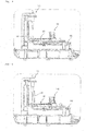
- Fig. 2 is a perspective view illustrating an in-vitro diagnosis apparatus used for the automatic in-vitro diagnosis method illustrated in Fig. 1
- Fig. 3 is a use state diagram illustrating a state in which a storage body is provided and moved to a transfer unit in a storage body providing step of the automatic in-vitro diagnosis method illustrated in Fig. 1
- Fig. 4 is a use state diagram illustrating a state in which after the storage body is provided and moved to the transfer unit, a suction tip is positioned under a suction unit in the automatic in-vitro diagnosis method illustrated in Fig. 1 , Fig.
- FIG. 5 is a use state diagram illustrating a state in which the suction tip is mounted in a suction tip mounting step of the automatic in-vitro diagnosis method illustrated in Fig. 1
- Fig. 6 is a use state diagram illustrating a state in which a specimen is sucked in a specimen suction step of the automatic in-vitro diagnosis method illustrated in Fig. 1
- Fig. 7 is a use state diagram illustrating a state in which the specimen is mixed with a reagent in a specimen and reagent mixing step of the automatic in-vitro diagnosis method illustrated in Fig. 1 , Fig.
- Fig. 8 is a use state diagram illustrating a state in which the mixture solution is dropped on an analysis strip in a mixture solution dropping step of the automatic in-vitro diagnosis method illustrated in Fig. 1
- Fig. 9 is a use state diagram illustrating a state in which the suction tip moves down to a removal position in a suction tip removing step of the automatic in-vitro diagnosis method illustrated in Fig. 1
- Fig. 10 is a use state diagram illustrating a state in which the suction tip is removed caught, while moving up from the removal position, in the suction tip removing step of the automatic in-vitro diagnosis method illustrated in Fig. 1
- Fig. 11 is a use state diagram illustrating a state in which the storage body is supplied to an analytic diagnosis unit and a diagnosis is made in a diagnosis step of the automatic in-vitro diagnosis method illustrated in Fig. 1 .
- a bodily secretion such as urine or excrement discharged from a human body or a body fluid such as blood, spinal fluid, various tissues, gastric fluid, or synovial fluid, which does not do any harm to the human body during extraction and is reproducible, is taken as a specimen, the specimen is mixed with a reagent which causes a chemically analyzable reaction according to the type of the specimen and a diagnosis purpose, and the mixture solution is optically analyzed. In this manner, a diagnosis is made automatically.
- the above-described automatic in-vitro diagnosis method comprises a step of providing a storage body (S10), a step of manipulating a manipulating display unit (S20), a step of mounting a suction tip (S30), a step of sucking a specimen (S40), a step of mixing a specimen and reagent (S50), a step of dropping a mixture solution (S60), a step of removing a suction tip (S70), a step of diagnosing (S80), and a step of discharging (S90).
- a storage body 120 that accommodates a specimen, a reagent to be mixed with the specimen, an analysis strip, and a suction tip 141 is supplied to a housing 110.
- the storage body 120 With the specimen to be diagnosed, the reagent causing a chemical reaction to the specimen, and the analysis strip on which the mixture solution of the specimen and the reagent is dropped, for analysis, contained in the storage body 120, the storage body 120 is inserted into the housing 110 from one side of the housing 110.
- a user manipulates a manipulating display unit 111 connected to a controller 112, for a diagnosis operation.
- use modes are displayed on the manipulating display unit 111.
- a process signal corresponding to the selected use mode is transmitted to the controller 112, to thereby automatically perform the diagnosis operation.
- a process signal corresponding to a user-selected use mode is transmitted to the controller 112 so that the diagnosis operation may be automatically performed.
- the suction tip 141 of the storage body 120 moved to a transfer unit 130 according to a signal of the controller 112 generated by manipulation is mounted to a suction unit 140 that provides suction pressure.
- the suction unit 140 moves up and down, applying the suction pressure to an upper part of the transfer unit 130.
- the transfer unit 130 moves the suction tip 141 containing a solution in the storage body 120 to under the suction unit 140.
- the suction unit 140 moves down, fits into the suction tip 141, and moves up and down with the suction tip 141, applying suction pressure.
- the suction tip 141 If after the suction tip 141 is mounted to the suction unit 140, the suction tip 141 is positioned above the position of a reagent stored in the storage body 120 in vacuum condition by operation of the transfer unit 130, the suction tip 141 moves down and releases the reagent from the vacuum state by puncturing.
- the suction tip 141 mounted to the suction unit 140 moves to the position of the reagent and sucks the reagent.
- the suction tip 141 After the suction tip 141 is mounted to the suction unit 140, the suction tip 141 moves up along with upward movement of the suction unit 140, and the storage body 120 is moved by operation of the transfer unit 130 so that the reagent contained in the storage body 120 may be positioned under the suction tip 141. Then, the suction tip 141 moves down by operation of the suction unit 140 and sucks the reagent into it with suction pressure applied by the suction unit 140.
- the suction unit 140 applies the suction pressure at a level suitable for a used volume of the specimen according to a signal from the controller 112 so that an accurate volume of the specimen may be supplied.
- the suction tip 141 that has sucked the specimen in it moves to the position of the reagent and mixes the sucked specimen with the reagent by successive suction and discharge.
- the suction unit 140 moves up, and the storage body 120 is transferred by operation of the transfer unit 130 so that the suction tip 141 is positioned above the position of the reagent. Then, the suction tip 141 moves down along with operation of the suction unit 140 and mixes the contained specimen with the reagent by successive suction and discharge with suction pressure.
- mixture solution S60 the mixture solution of the specimen and the reagent is dropped on the analysis strip contained in the storage body 120.
- the suction tip 141 moves up along with operation of the suction unit 140. Then, when the storage body 120 is transferred by operation of the transfer unit 130 so that the suction tip 141 may be positioned above a drop position of the analysis strip, the suction tip 141 moves down along with operation of the suction unit 140. If the suction tip 141 reaches the drop position of the analysis strip, the suction tip 141 drops the mixture solution onto the analysis strip along with release of the suction pressure.
- the suction tip 141 In the step of removing suction tip S70, the suction tip 141, which has dropped the mixture solution, moves up and down. During the up and down movement, the suction tip 141 is caught in the transfer unit 130 and thus removed to the outside.
- the transfer unit 130 moves to the other side. Subsequently, the suction tip 141 moves down to a position at which it will be caught in an end of the transfer unit 130, and the transfer unit 130 moves to a side at which the suction tip 141 will be caught. Then, the suction tip 141 moves up and is caught in the transfer unit 130. Thus, the suction tip 141 is removed down.
- the analysis strip having the mixture solution dropped on it is moved to an analytic diagnosis unit 150 that optically makes an analytic diagnosis, by operation of the transfer unit 130.
- the analytic diagnosis unit 150 measures fluorescent and chemical luminosity or absorbance by chromatography analysis.
- manipulating display unit 111 provided on a side surface of the housing 110 may display a diagnosis result of the analytic diagnosis unit 150 so that the user may view the diagnosis result.
- the diagnosis result of the analytic diagnosis unit 150 may be printed onto a sheet of paper by a printer 113 provided on the housing 110.
- the analysis strip into which the mixture solution has been absorbed is transferred to the analytic diagnosis unit 150 for optical analysis, and then an analytic diagnosis is made.
- a diagnosis result may be displayed as an image on the manipulating display unit 111 or output on a sheet of paper through the printer 113.
- the storage body 120 is discharged to the outside by operation of the transfer unit 130.
- the storage body 120 is discharged by operation of the transfer unit 130. Thus, the test is finished.
- the automatic in-vitro diagnosis method Since a specimen taken from a human body is automatically mixed with a reagent in accurate volumes, the mixture is absorbed with an analysis strip for a predetermined time, and then a diagnosis is made in order to diagnose the state of a person to be diagnosed with the specimen, the automatic in-vitro diagnosis method increases diagnostic reliability and a diagnosis speed. Therefore, the automatic in-vitro diagnosis method is useful in the in-vitro diagnosis industry.
Landscapes
- Health & Medical Sciences (AREA)
- Life Sciences & Earth Sciences (AREA)
- Chemical & Material Sciences (AREA)
- Immunology (AREA)
- Physics & Mathematics (AREA)
- Engineering & Computer Science (AREA)
- General Health & Medical Sciences (AREA)
- Biochemistry (AREA)
- Pathology (AREA)
- General Physics & Mathematics (AREA)
- Analytical Chemistry (AREA)
- Hematology (AREA)
- Biomedical Technology (AREA)
- Molecular Biology (AREA)
- Urology & Nephrology (AREA)
- Food Science & Technology (AREA)
- Medicinal Chemistry (AREA)
- Microbiology (AREA)
- Cell Biology (AREA)
- Biotechnology (AREA)
- Spectroscopy & Molecular Physics (AREA)
- Biophysics (AREA)
- Automatic Analysis And Handling Materials Therefor (AREA)
- Sampling And Sample Adjustment (AREA)
Description
- The present invention relates to an automatic in-vitro diagnosis method, and more particularly, to an automatic in-vitro diagnosis method for increasing diagnostic reliability and a diagnosis speed by automatically mixing a specimen taken from the body of a person with a reagent in volumes needed to diagnose the state of the person using the specimen, absorbing the mixture solution of the reagent and the specimen with an analysis strip for a predetermined time, and making a diagnosis by analysis.
- In general, In-Vitro Diagnostics (IVD) is a diagnosis technique of taking a body fluid as a specimen, such as blood, urine, excrement, spinal fluid, various tissues, gastric fluid, or synovial fluid, from a human body and making a diagnosis by optically detecting chemical properties using a reagent reacting to the specimen.
- Typically, a clinic makes an in-vitro diagnosis by extracting a necessary specimen from a human body, post-processing the extracted specimen, for example, by cultivation or separation in a laboratory, and diagnosing the specimen through interpretation using a magnifying tool such as a microscope or other analysis tools by a tester having medical knowledge. This in-vitro diagnosis technique takes expensive equipment and many personnel, thus increasing cost.
- The in-vitro diagnosis technique is used to make a diagnosis of a specific disease or evaluate the state of a patient in a clinic by taking a specimen from the patient and testing the specimen in the departments of diagnostic medicine and pathology.
- Recently, a specific reagent chemically reacting to an extracted specimen has been developed and an in-vitro diagnosis has been made by optically analyzing features resulting from chemical reaction between the specimen and the reagent in some diagnostic tests.
- In such an in-vitro diagnosis, a material such as blood or urine is taken as a specimen from a human body, mixed with a reagent causing chemical reaction according to the type of the specimen and a diagnosis purpose, and analyzed by means of an analyzer. The in-vitro diagnosis is used for diagnosis such as immunological diagnosis, clinical diagnosis, clinical microbiological diagnosis, tissue diagnosis, molecular diagnosis, self-blood sugar metering, in-situ testing, and hemostasis testing.
- In the in-vitro diagnosis technique as described above, a specimen suitable for a test is selected from materials taken from a human body, such as blood and urine, mixed with a reagent prepared according to the specimen and a test method, absorbed with an analysis strip, and diagnosed by means of a diagnostic device such as a laser beam-based fluorescent diagnostic device.
- In the conventional in-vitro diagnosis device, however, an operator manually introduces and mixes a specimen and a reagent using a manual suction tool, pipette. Therefore, the volumes of the specimen and the reagent are different according to the skill of the operator and a task state, thereby decreasing diagnostic reliability.
- Moreover, the mixture of the specimen and the reagent is dropped on an analysis strip formed of an absorbing material, and an analysis should be made after a predetermined time over which the mixture is absorbed into the analysis strop. However, the volumes of the dropped specimen and reagent may differ according to the skill of the operator and the task state, and it may take a different time to absolve the mixture with the analysis strip. As a result, diagnostic reliability is decreased significantly.
- Since the specimen has been taken from the human body and thus is vulnerable to contamination or component transform with the passage of time due to external factors such as temperature, foreign materials, and humidity, a diagnosis should be made rapidly. However, a manual diagnosis may suffer time delay and thus contamination or component transform of the specimen, thereby decreasing the accuracy of a diagnosis result.
WO 02/059563 A2 - An object of the present invention devised to solve the conventional problem is to provide an automatic in-vitro diagnosis method for increasing diagnostic reliability and a diagnosis speed by automatically mixing a specimen taken from the body of a person to be diagnosed with a reagent, in accurate volumes, absorbing the mixture with an analysis strip for a predetermined time, and then making a diagnosis in order to diagnose the state of the person by means of the specimen.
- It will be appreciated by persons skilled in the art that the objects that could be achieved with the present invention are not limited to what has been particularly described hereinabove and the above and other objects that the present invention could achieve will be more clearly understood from the following detailed description.
- The present invention is defined in the independent claim 1. The dependent claims define embodiments of the invention. In an aspect of the present invention, an automatic in-vitro diagnosis method for automatically performing a diagnosis by analyzing a specimen taken from a human body comprises providing a storage body to a housing, the storage body containing the specimen, a reagent to be mixed with specimen, an analysis strip, and a suction tip, and manipulating diagnosis operation on a manipulating a display unit connected to a controller by a user, mounting the suction tip of the storage body to a suction unit for applying suction pressure, the storage body being moved to a transfer unit according to a control signal of the controller upon the manipulation, moving the mounted suction tip to a position of the specimen, and sucking the specimen with the suction tip, moving the suction tip which suck the specimen to a position of the reagent, and mixing the specimen with the reagent through successive suction and discharge, dropping the mixture solution of the specimen and the reagent onto the analysis strip contained in the storage body, and removing the suction tip to the outside by allowing the suction tip to be caught in the transfer unit, while moving up and down the suction tip after the dropping, moving the analysis strip on which the mixture solution dropped to an analytic diagnosis unit for optically making an analytic diagnosis, and diagnosing and discharging the storage body to the outside by operating the transfer unit, after the diagnosis.
- A use modes may be displayed on the manipulating display unit provided on one side surface of the housing, and the manipulating of a diagnosis operation may comprises, if the use mode is selected, transmitting a process signal corresponding to the selected use mode to the controller, and automatically performing the diagnosis operation.
- The suction unit may be configured to move up and down, applying suction pressure to an upper part of the transfer unit, suck the specimen, mix the specimen with the reagent, and applies the suction pressure while moving up and down when the mixture solution is dropped onto the analysis strip.
- The diagnosing step may comprises displaying the diagnosis result of the analytic diagnosis unit on the manipulating display unit provided on one side surface of the housing to enable a user to view the diagnosis result.
- The diagnosing may comprises printing the diagnosis result of the analytic diagnosis unit on a sheet of paper through a printer provided on the housing.
- The sucking of the specimen with the suction tip may comprises, after the suction tip is mounted to the suction unit and before the specimen sucked, when the suction tip is positioned at a position of the reagent stored in the storage body in a vacuum state by operating the transfer unit, moving down the suction tip and releasing the reagent from the vacuum state by puncturing.
- The diagnosing may comprises measuring fluorescent and chemical luminosity or absorbance using chromatography analysis by the analytic diagnosis unit.
- Details of other embodiments are incorporated in the detailed description and the drawings.
- According to an in-vitro diagnosis method according to an embodiment of the present invention, since a specimen taken from the body of a person to be diagnosed is automatically mixed with an reagent, in accurate volumes, the mixture is absorbed with an analysis strip for a predetermined time, and then a diagnosis is made, in order to diagnose the state of the person by means of the specimen, diagnostic reliability and a diagnosis speed can be increased.
- Further, in the automatic in-vitro diagnosis method of the present invention, the reagent and the specimen to be mixed for diagnosis are supplied automatically accurately with accurate suction pressure, and mixed accurately by repeated suction and spraying. Therefore, the mixture solution of the reagent and the specimen is supplied at an accurate ratio in a volume needed for diagnosis, thereby increasing diagnostic reliability.
- According to the automatic in-vitro diagnosis method of the present invention, the mixture solution of the reagent and the specimen is automatically dropped on an accurate position of the analysis strip and automatically supplied to an analytic diagnosis unit a predetermined time later. Therefore, as an accurate time is delayed to allow the analysis strip to absorb an accurate volume of the mixture solution dropped on the analysis strip, diagnostic reliability can be increased.
- Also, since suction, mixing, dropping, and analytic diagnosis are performed automatically by sideways movement of a transfer unit and up and down movement of a suction unit which moves a specimen, a reagent, and an analysis strip to the transfer unit, applying suction pressure to them and which is supported inserted into a suction tip replaced at each diagnosis, the suction tip is replaced at each diagnosis and thus sanitary, and the automatic proceedings shorten a diagnosis time in the automatic in-vitro diagnosis method of the present invention. Accordingly, a diagnosis speed can be increased.
- It will be appreciated by persons skilled in the art that the effects that can be achieved with the present invention are not limited to what has been particularly described hereinabove and other advantages of the present invention will be more clearly understood from the following detailed description taken in conjunction with the accompanying drawings.
-
-
Fig. 1 is a flowchart illustrating an automatic in-vitro diagnosis method according to an embodiment of the present invention. -
Fig. 2 is a perspective view illustrating an in-vitro diagnosis apparatus used for the automatic in-vitro diagnosis method illustrated inFig. 1 . -
Fig. 3 is a use state diagram illustrating a state in which a storage body is provided and moved to a transfer unit in a storage body providing step of the automatic in-vitro diagnosis method illustrated inFig. 1 . -
Fig. 4 is a use state diagram illustrating a state in which after the storage body is provided and moved to the transfer unit, a suction tip is positioned under a suction unit in the automatic in-vitro diagnosis method illustrated inFig. 1 . -
Fig. 5 is a use state diagram illustrating a state in which the suction tip is mounted in a suction tip mounting step of the automatic in-vitro diagnosis method illustrated inFig. 1 . -
Fig. 6 is a use state diagram illustrating a state in which a specimen is sucked in a specimen suction step of the automatic in-vitro diagnosis method illustrated inFig. 1 . -
Fig. 7 is a use state diagram illustrating a state in which the specimen is mixed with a reagent in a specimen and reagent mixing step of the automatic in-vitro diagnosis method illustrated inFig. 1 . -
Fig. 8 is a use state diagram illustrating a state in which the mixture solution is dropped on an analysis strip in a mixture solution dropping step of the automatic in-vitro diagnosis method illustrated inFig. 1 . -
Fig. 9 is a use state diagram illustrating a state in which the suction tip moves down to a removal position in a suction tip removing step of the automatic in-vitro diagnosis method illustrated inFig. 1 . -
Fig. 10 is a use state diagram illustrating a state in which the suction tip is removed caught, while rising from the removal position in the suction tip removing step of the automatic in-vitro diagnosis method illustrated inFig. 1 . -
Fig. 11 is a use state diagram illustrating a state in which the storage body is supplied to an analytic diagnosis unit and a diagnosis is made in a diagnosis step of the automatic in-vitro diagnosis method illustrated inFig. 1 . - With reference to the attached drawings, a preferred embodiment of the present invention will be described in detail so that those skilled in the art may readily practice the present invention.
- A description of technical contents which are known to the field of the present invention and have no direct relation to the present invention is omitted in the following description of the embodiment, lest it should not obscure the subject matter of the present invention.
- For the same reason, some components are shown as exaggerated, omitted, or schematic in the attached drawings. Also, the size of each component does not match its actual size all the time. Like reference numerals denote the same or corresponding components in the drawings.
- Now, a description will be given of an automatic in-vitro diagnosis method according to an embodiment of the present invention with reference to the attached drawings.
-
Fig. 1 is a flowchart illustrating an automatic in-vitro diagnosis method according to an embodiment of the present invention,Fig. 2 is a perspective view illustrating an in-vitro diagnosis apparatus used for the automatic in-vitro diagnosis method illustrated inFig. 1 ,Fig. 3 is a use state diagram illustrating a state in which a storage body is provided and moved to a transfer unit in a storage body providing step of the automatic in-vitro diagnosis method illustrated inFig. 1 ,Fig. 4 is a use state diagram illustrating a state in which after the storage body is provided and moved to the transfer unit, a suction tip is positioned under a suction unit in the automatic in-vitro diagnosis method illustrated inFig. 1 ,Fig. 5 is a use state diagram illustrating a state in which the suction tip is mounted in a suction tip mounting step of the automatic in-vitro diagnosis method illustrated inFig. 1 ,Fig. 6 is a use state diagram illustrating a state in which a specimen is sucked in a specimen suction step of the automatic in-vitro diagnosis method illustrated inFig. 1 ,Fig. 7 is a use state diagram illustrating a state in which the specimen is mixed with a reagent in a specimen and reagent mixing step of the automatic in-vitro diagnosis method illustrated inFig. 1 ,Fig. 8 is a use state diagram illustrating a state in which the mixture solution is dropped on an analysis strip in a mixture solution dropping step of the automatic in-vitro diagnosis method illustrated inFig. 1 ,Fig. 9 is a use state diagram illustrating a state in which the suction tip moves down to a removal position in a suction tip removing step of the automatic in-vitro diagnosis method illustrated inFig. 1 ,Fig. 10 is a use state diagram illustrating a state in which the suction tip is removed caught, while moving up from the removal position, in the suction tip removing step of the automatic in-vitro diagnosis method illustrated inFig. 1 , andFig. 11 is a use state diagram illustrating a state in which the storage body is supplied to an analytic diagnosis unit and a diagnosis is made in a diagnosis step of the automatic in-vitro diagnosis method illustrated inFig. 1 . - Referring to
Figs. 1 to 11 , in an automatic in-vitro diagnosis method according to an embodiment of the present invention, a bodily secretion such as urine or excrement discharged from a human body or a body fluid such as blood, spinal fluid, various tissues, gastric fluid, or synovial fluid, which does not do any harm to the human body during extraction and is reproducible, is taken as a specimen, the specimen is mixed with a reagent which causes a chemically analyzable reaction according to the type of the specimen and a diagnosis purpose, and the mixture solution is optically analyzed. In this manner, a diagnosis is made automatically. - The above-described automatic in-vitro diagnosis method comprises a step of providing a storage body (S10), a step of manipulating a manipulating display unit (S20), a step of mounting a suction tip (S30), a step of sucking a specimen (S40), a step of mixing a specimen and reagent (S50), a step of dropping a mixture solution (S60), a step of removing a suction tip (S70), a step of diagnosing (S80), and a step of discharging (S90).
- In the step of providing storage body S10, a
storage body 120 that accommodates a specimen, a reagent to be mixed with the specimen, an analysis strip, and asuction tip 141 is supplied to ahousing 110. - With the specimen to be diagnosed, the reagent causing a chemical reaction to the specimen, and the analysis strip on which the mixture solution of the specimen and the reagent is dropped, for analysis, contained in the
storage body 120, thestorage body 120 is inserted into thehousing 110 from one side of thehousing 110. - In the step of manipulating a manipulating display unit S20, a user manipulates a manipulating
display unit 111 connected to acontroller 112, for a diagnosis operation. - After the
storage body 120 is inserted, use modes are displayed on the manipulatingdisplay unit 111. Upon user selection of a use mode, a process signal corresponding to the selected use mode is transmitted to thecontroller 112, to thereby automatically perform the diagnosis operation. - There are a plurality of use modes having process signals to operate the
controller 112 according to specimen types and diagnosis purposes. A process signal corresponding to a user-selected use mode is transmitted to thecontroller 112 so that the diagnosis operation may be automatically performed. - In the step of mounting suction tip S30, the
suction tip 141 of thestorage body 120 moved to atransfer unit 130 according to a signal of thecontroller 112 generated by manipulation is mounted to asuction unit 140 that provides suction pressure. Thesuction unit 140 moves up and down, applying the suction pressure to an upper part of thetransfer unit 130. - As the
transfer unit 130 is operated by the signal from thecontroller 112, thetransfer unit 130 moves thesuction tip 141 containing a solution in thestorage body 120 to under thesuction unit 140. Thesuction unit 140 moves down, fits into thesuction tip 141, and moves up and down with thesuction tip 141, applying suction pressure. - If after the
suction tip 141 is mounted to thesuction unit 140, thesuction tip 141 is positioned above the position of a reagent stored in thestorage body 120 in vacuum condition by operation of thetransfer unit 130, thesuction tip 141 moves down and releases the reagent from the vacuum state by puncturing. - In the step of sucking specimen S40, the
suction tip 141 mounted to thesuction unit 140 moves to the position of the reagent and sucks the reagent. - After the
suction tip 141 is mounted to thesuction unit 140, thesuction tip 141 moves up along with upward movement of thesuction unit 140, and thestorage body 120 is moved by operation of thetransfer unit 130 so that the reagent contained in thestorage body 120 may be positioned under thesuction tip 141. Then, thesuction tip 141 moves down by operation of thesuction unit 140 and sucks the reagent into it with suction pressure applied by thesuction unit 140. Herein, thesuction unit 140 applies the suction pressure at a level suitable for a used volume of the specimen according to a signal from thecontroller 112 so that an accurate volume of the specimen may be supplied. - In the step of mixing specimen and reagent S50, the
suction tip 141 that has sucked the specimen in it moves to the position of the reagent and mixes the sucked specimen with the reagent by successive suction and discharge. - With the specimen sucked into the
suction tip 141, thesuction unit 140 moves up, and thestorage body 120 is transferred by operation of thetransfer unit 130 so that thesuction tip 141 is positioned above the position of the reagent. Then, thesuction tip 141 moves down along with operation of thesuction unit 140 and mixes the contained specimen with the reagent by successive suction and discharge with suction pressure. - In the step of dropping mixture solution S60, the mixture solution of the specimen and the reagent is dropped on the analysis strip contained in the
storage body 120. - With the mixture of the specimen and the reagent contained in the
suction tip 141, thesuction tip 141 moves up along with operation of thesuction unit 140. Then, when thestorage body 120 is transferred by operation of thetransfer unit 130 so that thesuction tip 141 may be positioned above a drop position of the analysis strip, thesuction tip 141 moves down along with operation of thesuction unit 140. If thesuction tip 141 reaches the drop position of the analysis strip, thesuction tip 141 drops the mixture solution onto the analysis strip along with release of the suction pressure. - In the step of removing suction tip S70, the
suction tip 141, which has dropped the mixture solution, moves up and down. During the up and down movement, thesuction tip 141 is caught in thetransfer unit 130 and thus removed to the outside. - After the
suction tip 141 finishing dropping the mixture solution moves up, thetransfer unit 130 moves to the other side. Subsequently, thesuction tip 141 moves down to a position at which it will be caught in an end of thetransfer unit 130, and thetransfer unit 130 moves to a side at which thesuction tip 141 will be caught. Then, thesuction tip 141 moves up and is caught in thetransfer unit 130. Thus, thesuction tip 141 is removed down. - In the step of diagnosing S80, the analysis strip having the mixture solution dropped on it is moved to an
analytic diagnosis unit 150 that optically makes an analytic diagnosis, by operation of thetransfer unit 130. - Preferably, the
analytic diagnosis unit 150 measures fluorescent and chemical luminosity or absorbance by chromatography analysis. - Further, the manipulating
display unit 111 provided on a side surface of thehousing 110 may display a diagnosis result of theanalytic diagnosis unit 150 so that the user may view the diagnosis result. - The diagnosis result of the
analytic diagnosis unit 150 may be printed onto a sheet of paper by aprinter 113 provided on thehousing 110. - After the suction tip 131 is removed, the analysis strip into which the mixture solution has been absorbed is transferred to the
analytic diagnosis unit 150 for optical analysis, and then an analytic diagnosis is made. After the diagnosis, a diagnosis result may be displayed as an image on the manipulatingdisplay unit 111 or output on a sheet of paper through theprinter 113. - In the discharge step S90, upon completion of the diagnosis and analysis, the
storage body 120 is discharged to the outside by operation of thetransfer unit 130. - After the diagnosis, the
storage body 120 is discharged by operation of thetransfer unit 130. Thus, the test is finished. - The preferred embodiment of the present invention has been described and illustrated in the present disclosure and the drawings. While specific terms are used, these terms are provided in general meanings in order to easily describe the technical aspects of the present invention and help the understanding of the present invention, not intended to limit the scope of the present invention. Accordingly, it is apparent to those skilled in the art that other modification examples can be implemented without departing from the scope of the present invention, in addition to the disclosed embodiment of the present invention.
- Since a specimen taken from a human body is automatically mixed with a reagent in accurate volumes, the mixture is absorbed with an analysis strip for a predetermined time, and then a diagnosis is made in order to diagnose the state of a person to be diagnosed with the specimen, the automatic in-vitro diagnosis method increases diagnostic reliability and a diagnosis speed. Therefore, the automatic in-vitro diagnosis method is useful in the in-vitro diagnosis industry.
Claims (7)
- An automatic in-vitro diagnosis method for automatically performing a diagnosis by analyzing a specimen taken from a human body, the method comprising:providing a storage body to a housing, the storage body containing the specimen, a reagent to be mixed with specimen, an analysis strip, and a suction tip, and manipulating diagnosis operation on a manipulating a display unit connected to a controller by a user;mounting the suction tip of the storage body to a suction unit for applying suction pressure, the storage body being moved to a transfer unit according to a control signal of the controller upon the manipulation, moving the mounted suction tip to a position of the specimen, and sucking the specimen with the suction tip;moving the suction tip which suck the specimen to a position of the reagent, and mixing the specimen with the reagent through successive suction and discharge;dropping the mixture solution of the specimen and the reagent onto the analysis strip contained in the storage body, and removing the suction tip to the outside by allowing the suction tip to be caught in the transfer unit, while moving up and down the suction tip after the droppingwherein, after the suction tip finished dropping the mixture solution, the suction tip moves up and the transfer unit moves to the other side, subsequently the suction tip moves down to a position at which it will be caught in an end of the transfer unit, and the transfer unit moves to a side at which the suction tip will be caught, then the suction tip moves up and is caught in the transfer unit, thus, the suction tip is removed down;moving the analysis strip on which the mixture solution dropped to an analytic diagnosis unit for optically making an analytic diagnosis, and diagnosing; anddischarging the storage body to the outside by operating the transfer unit, after the diagnosis.
- The automatic in-vitro diagnosis method according to claim 1, wherein a use modes are displayed on the manipulating display unit provided on one side surface of the housing, and the manipulating of a diagnosis operation comprises, if the use mode is selected, transmitting a process signal corresponding to the selected use mode to the controller, and automatically performing the diagnosis operation.
- The automatic in-vitro diagnosis method according to claim 1, wherein the suction unit is configured to move up and down, applying suction pressure to an upper part of the transfer unit, suck the specimen, mix the specimen with the reagent, and applies the suction pressure while moving up and down when the mixture solution is dropped onto the analysis strip.
- The automatic in-vitro diagnosis method according to claim 1, wherein the diagnosing comprises displaying the diagnosis result of the analytic diagnosis unit on the manipulating display unit provided on one side surface of the housing to enable a user to view the diagnosis result.
- The automatic in-vitro diagnosis method according to claim 1, wherein the diagnosing comprises printing the diagnosis result of the analytic diagnosis unit on a sheet of paper through a printer provided on the housing.
- The automatic in-vitro diagnosis method according to claim 1, wherein the sucking of the specimen with the suction tip comprises, after the suction tip is mounted to the suction unit and before the specimen sucked, when the suction tip is positioned at a position of the reagent stored in the storage body in a vacuum state by operating the transfer unit, moving down the suction tip and releasing the reagent from the vacuum state by puncturing.
- The automatic in-vitro diagnosis method according to claim 1, wherein the diagnosing comprises measuring fluorescent and chemical luminosity or absorbance using chromatography analysis by the analytic diagnosis unit.
Applications Claiming Priority (2)
| Application Number | Priority Date | Filing Date | Title |
|---|---|---|---|
| KR1020130140186A KR101770679B1 (en) | 2013-11-18 | 2013-11-18 | Method of in vitro automatic diagnostics |
| PCT/KR2014/009282 WO2015072663A2 (en) | 2013-11-18 | 2014-10-01 | Method for automatic in vitro diagnosis |
Publications (3)
| Publication Number | Publication Date |
|---|---|
| EP3073272A2 EP3073272A2 (en) | 2016-09-28 |
| EP3073272A4 EP3073272A4 (en) | 2017-08-16 |
| EP3073272B1 true EP3073272B1 (en) | 2019-06-19 |
Family
ID=53058220
Family Applications (1)
| Application Number | Title | Priority Date | Filing Date |
|---|---|---|---|
| EP14862749.0A Active EP3073272B1 (en) | 2013-11-18 | 2014-10-01 | Method for automatic in vitro diagnosis |
Country Status (7)
| Country | Link |
|---|---|
| US (1) | US9880136B2 (en) |
| EP (1) | EP3073272B1 (en) |
| JP (1) | JP6570522B2 (en) |
| KR (1) | KR101770679B1 (en) |
| CN (1) | CN105765390A (en) |
| ES (1) | ES2745423T3 (en) |
| WO (1) | WO2015072663A2 (en) |
Families Citing this family (5)
| Publication number | Priority date | Publication date | Assignee | Title |
|---|---|---|---|---|
| KR101811786B1 (en) | 2015-05-14 | 2017-12-22 | 바디텍메드(주) | Station for test device with integrated reaction and detection means |
| US10871474B2 (en) | 2015-05-14 | 2020-12-22 | Boditech Med Inc. | System and method for analyzing biological fluid in multiple cuvettes |
| JP6814171B2 (en) * | 2018-03-19 | 2021-01-13 | 株式会社日立ハイテク | Automatic analyzer |
| KR102867751B1 (en) * | 2022-03-29 | 2025-10-14 | 주식회사 앱솔로지 | Vitro diagnostic device |
| EP4575508A1 (en) * | 2023-12-22 | 2025-06-25 | Tecan Trading AG | Method, computer program and laboratory automation device for aspirating a liquid out of a vial, controller for controlling the laboratory automation device, and computer-readable medium |
Family Cites Families (18)
| Publication number | Priority date | Publication date | Assignee | Title |
|---|---|---|---|---|
| JPS61181968A (en) * | 1984-12-18 | 1986-08-14 | シタス コ−ポレイシヨン | Liquid treating system of large number of sample |
| AU639575B2 (en) * | 1990-05-01 | 1993-07-29 | Enprotech Corporation | Integral biomolecule preparation device |
| US5158869A (en) * | 1990-07-06 | 1992-10-27 | Sangstat Medical Corporation | Analyte determination using comparison of juxtaposed competitive and non-competitive elisa results and device therefore |
| DE69434638T2 (en) * | 1993-09-24 | 2006-12-14 | Abbott Laboratories, Abbott Park | Operating procedure for a continuous and random access automatic analysis system for performing multiple determinations on a plurality of liquid samples simultaneously |
| JP3403839B2 (en) * | 1994-10-27 | 2003-05-06 | プレシジョン・システム・サイエンス株式会社 | Cartridge container |
| JP3294991B2 (en) * | 1995-05-29 | 2002-06-24 | 株式会社日立製作所 | Analyzer using disposable reaction vessel |
| JPH09196917A (en) * | 1996-01-12 | 1997-07-31 | Suzuki Motor Corp | Automatic determination device for test plate |
| US7390675B2 (en) * | 1999-10-15 | 2008-06-24 | Christopher Feistel | Multi-functional and configurable assay |
| JP3793782B2 (en) * | 2000-07-24 | 2006-07-05 | アークレイ株式会社 | Measuring apparatus, reagent carrier and information recording medium used therefor, measuring data correction method, and program recording medium |
| CN1253238C (en) * | 2001-01-26 | 2006-04-26 | 阿德维昂生物科学公司 | Robotic autosampler for automated electrospray from microfluidic chip |
| JP4474099B2 (en) * | 2002-12-20 | 2010-06-02 | アークレイ株式会社 | Liquid storage container and cartridge |
| US7597847B2 (en) * | 2003-03-31 | 2009-10-06 | Ortho-Clinical Diagnostics, Inc. | Analyzer having a stationary multifunction probe |
| US20040230400A1 (en) | 2003-05-13 | 2004-11-18 | Tomasso David Angelo | Analyzer having concentric rotors |
| JP2005009868A (en) * | 2003-06-16 | 2005-01-13 | Fuji Photo Film Co Ltd | Autoanalyzer |
| US20100178204A1 (en) | 2006-08-21 | 2010-07-15 | Anp Technologies | Automated Self-Contained Liquid Handling and Detection System Device |
| JP4964547B2 (en) * | 2006-09-21 | 2012-07-04 | 株式会社サカエ | Automatic analyzer |
| WO2008096776A1 (en) * | 2007-02-07 | 2008-08-14 | Universal Bio Research Co., Ltd. | Magnetic particle parallel processing apparatus permitting repeated use of container and method of magnetic particle parallel processing permitting repeated use of container |
| US8435738B2 (en) * | 2011-09-25 | 2013-05-07 | Theranos, Inc. | Systems and methods for multi-analysis |
-
2013
- 2013-11-18 KR KR1020130140186A patent/KR101770679B1/en active Active
-
2014
- 2014-10-01 ES ES14862749T patent/ES2745423T3/en active Active
- 2014-10-01 EP EP14862749.0A patent/EP3073272B1/en active Active
- 2014-10-01 US US15/037,330 patent/US9880136B2/en active Active
- 2014-10-01 WO PCT/KR2014/009282 patent/WO2015072663A2/en not_active Ceased
- 2014-10-01 CN CN201480062925.7A patent/CN105765390A/en active Pending
- 2014-10-01 JP JP2016532585A patent/JP6570522B2/en active Active
Non-Patent Citations (1)
| Title |
|---|
| None * |
Also Published As
| Publication number | Publication date |
|---|---|
| EP3073272A4 (en) | 2017-08-16 |
| ES2745423T3 (en) | 2020-03-02 |
| KR101770679B1 (en) | 2017-08-23 |
| CN105765390A (en) | 2016-07-13 |
| US20160290975A1 (en) | 2016-10-06 |
| JP2016538551A (en) | 2016-12-08 |
| JP6570522B2 (en) | 2019-09-04 |
| US9880136B2 (en) | 2018-01-30 |
| KR20150057181A (en) | 2015-05-28 |
| WO2015072663A2 (en) | 2015-05-21 |
| EP3073272A2 (en) | 2016-09-28 |
Similar Documents
| Publication | Publication Date | Title |
|---|---|---|
| JP7187552B2 (en) | Analytical device and analyzer for use therewith | |
| JP6770107B2 (en) | system | |
| EP1186893B1 (en) | Analyzer with sample quality measurement, and method | |
| US20120101407A1 (en) | Apparatus and method for preparation of small volume of samples | |
| US9880136B2 (en) | Method for automatic in vitro diagnosis | |
| JP2000266759A (en) | Chemical analyzer and chemical analysis system | |
| JP4111179B2 (en) | Chemical analyzer and chemical analysis system | |
| US11125738B2 (en) | Blood sample analysis systems and methods | |
| KR20080033457A (en) | Apparatus and Methods for Detecting Analytes | |
| KR20160051253A (en) | A cartridge of assay apparatus for in vitro diagnosis | |
| CN111819449B (en) | automatic analysis device | |
| CN102103146A (en) | System and process for analyzing liquid sample | |
| JP2017223656A (en) | Syringe assembly and method of using the same | |
| JP2013532834A (en) | Chemical and / or biological analysis method and apparatus | |
| US11567097B2 (en) | Apparatus for optically monitoring a dosing of a liquid to be pipetted | |
| JP2011137676A (en) | Dispensing apparatus, automatic analyzer, and method of measuring amount of liquid | |
| Volod et al. | The TEG 5000 System: System Description and Protocol for Measurements | |
| KR20210155460A (en) | Rt-pcr device | |
| JP2022107553A (en) | Inspection chip measuring device | |
| US20190204347A1 (en) | Automated analyzer and retesting instruction system | |
| ES3030329T3 (en) | Automatic sampling method for handling whole blood | |
| KR102808675B1 (en) | System for specimen analysis | |
| KR101764300B1 (en) | Reagent cartridge having a cone-type injection opening | |
| JP2007093482A (en) | Pre-processing mechanism for sample testing device, sample storage cassette and sample mounting unit | |
| EP2077446A1 (en) | Method of determining abnormality and analyzer |
Legal Events
| Date | Code | Title | Description |
|---|---|---|---|
| PUAI | Public reference made under article 153(3) epc to a published international application that has entered the european phase |
Free format text: ORIGINAL CODE: 0009012 |
|
| 17P | Request for examination filed |
Effective date: 20160620 |
|
| AK | Designated contracting states |
Kind code of ref document: A2 Designated state(s): AL AT BE BG CH CY CZ DE DK EE ES FI FR GB GR HR HU IE IS IT LI LT LU LV MC MK MT NL NO PL PT RO RS SE SI SK SM TR |
|
| AX | Request for extension of the european patent |
Extension state: BA ME |
|
| DAX | Request for extension of the european patent (deleted) | ||
| A4 | Supplementary search report drawn up and despatched |
Effective date: 20170717 |
|
| RIC1 | Information provided on ipc code assigned before grant |
Ipc: G01N 33/52 20060101ALI20170711BHEP Ipc: G01N 35/10 20060101AFI20170711BHEP Ipc: G01N 33/483 20060101ALI20170711BHEP Ipc: G01N 33/53 20060101ALI20170711BHEP |
|
| STAA | Information on the status of an ep patent application or granted ep patent |
Free format text: STATUS: EXAMINATION IS IN PROGRESS |
|
| 17Q | First examination report despatched |
Effective date: 20180618 |
|
| GRAP | Despatch of communication of intention to grant a patent |
Free format text: ORIGINAL CODE: EPIDOSNIGR1 |
|
| STAA | Information on the status of an ep patent application or granted ep patent |
Free format text: STATUS: GRANT OF PATENT IS INTENDED |
|
| INTG | Intention to grant announced |
Effective date: 20190208 |
|
| GRAS | Grant fee paid |
Free format text: ORIGINAL CODE: EPIDOSNIGR3 |
|
| GRAA | (expected) grant |
Free format text: ORIGINAL CODE: 0009210 |
|
| STAA | Information on the status of an ep patent application or granted ep patent |
Free format text: STATUS: THE PATENT HAS BEEN GRANTED |
|
| AK | Designated contracting states |
Kind code of ref document: B1 Designated state(s): AL AT BE BG CH CY CZ DE DK EE ES FI FR GB GR HR HU IE IS IT LI LT LU LV MC MK MT NL NO PL PT RO RS SE SI SK SM TR |
|
| REG | Reference to a national code |
Ref country code: GB Ref legal event code: FG4D |
|
| REG | Reference to a national code |
Ref country code: CH Ref legal event code: EP |
|
| REG | Reference to a national code |
Ref country code: IE Ref legal event code: FG4D |
|
| REG | Reference to a national code |
Ref country code: DE Ref legal event code: R096 Ref document number: 602014048840 Country of ref document: DE |
|
| REG | Reference to a national code |
Ref country code: CH Ref legal event code: NV Representative=s name: RENTSCH PARTNER AG, CH Ref country code: AT Ref legal event code: REF Ref document number: 1146188 Country of ref document: AT Kind code of ref document: T Effective date: 20190715 |
|
| REG | Reference to a national code |
Ref country code: NL Ref legal event code: FP |
|
| PG25 | Lapsed in a contracting state [announced via postgrant information from national office to epo] |
Ref country code: AL Free format text: LAPSE BECAUSE OF FAILURE TO SUBMIT A TRANSLATION OF THE DESCRIPTION OR TO PAY THE FEE WITHIN THE PRESCRIBED TIME-LIMIT Effective date: 20190619 Ref country code: SE Free format text: LAPSE BECAUSE OF FAILURE TO SUBMIT A TRANSLATION OF THE DESCRIPTION OR TO PAY THE FEE WITHIN THE PRESCRIBED TIME-LIMIT Effective date: 20190619 Ref country code: FI Free format text: LAPSE BECAUSE OF FAILURE TO SUBMIT A TRANSLATION OF THE DESCRIPTION OR TO PAY THE FEE WITHIN THE PRESCRIBED TIME-LIMIT Effective date: 20190619 Ref country code: NO Free format text: LAPSE BECAUSE OF FAILURE TO SUBMIT A TRANSLATION OF THE DESCRIPTION OR TO PAY THE FEE WITHIN THE PRESCRIBED TIME-LIMIT Effective date: 20190919 Ref country code: HR Free format text: LAPSE BECAUSE OF FAILURE TO SUBMIT A TRANSLATION OF THE DESCRIPTION OR TO PAY THE FEE WITHIN THE PRESCRIBED TIME-LIMIT Effective date: 20190619 Ref country code: LT Free format text: LAPSE BECAUSE OF FAILURE TO SUBMIT A TRANSLATION OF THE DESCRIPTION OR TO PAY THE FEE WITHIN THE PRESCRIBED TIME-LIMIT Effective date: 20190619 |
|
| REG | Reference to a national code |
Ref country code: LT Ref legal event code: MG4D |
|
| PG25 | Lapsed in a contracting state [announced via postgrant information from national office to epo] |
Ref country code: RS Free format text: LAPSE BECAUSE OF FAILURE TO SUBMIT A TRANSLATION OF THE DESCRIPTION OR TO PAY THE FEE WITHIN THE PRESCRIBED TIME-LIMIT Effective date: 20190619 Ref country code: BG Free format text: LAPSE BECAUSE OF FAILURE TO SUBMIT A TRANSLATION OF THE DESCRIPTION OR TO PAY THE FEE WITHIN THE PRESCRIBED TIME-LIMIT Effective date: 20190919 Ref country code: GR Free format text: LAPSE BECAUSE OF FAILURE TO SUBMIT A TRANSLATION OF THE DESCRIPTION OR TO PAY THE FEE WITHIN THE PRESCRIBED TIME-LIMIT Effective date: 20190920 Ref country code: LV Free format text: LAPSE BECAUSE OF FAILURE TO SUBMIT A TRANSLATION OF THE DESCRIPTION OR TO PAY THE FEE WITHIN THE PRESCRIBED TIME-LIMIT Effective date: 20190619 |
|
| REG | Reference to a national code |
Ref country code: AT Ref legal event code: MK05 Ref document number: 1146188 Country of ref document: AT Kind code of ref document: T Effective date: 20190619 |
|
| PG25 | Lapsed in a contracting state [announced via postgrant information from national office to epo] |
Ref country code: EE Free format text: LAPSE BECAUSE OF FAILURE TO SUBMIT A TRANSLATION OF THE DESCRIPTION OR TO PAY THE FEE WITHIN THE PRESCRIBED TIME-LIMIT Effective date: 20190619 Ref country code: AT Free format text: LAPSE BECAUSE OF FAILURE TO SUBMIT A TRANSLATION OF THE DESCRIPTION OR TO PAY THE FEE WITHIN THE PRESCRIBED TIME-LIMIT Effective date: 20190619 Ref country code: PT Free format text: LAPSE BECAUSE OF FAILURE TO SUBMIT A TRANSLATION OF THE DESCRIPTION OR TO PAY THE FEE WITHIN THE PRESCRIBED TIME-LIMIT Effective date: 20191021 Ref country code: SK Free format text: LAPSE BECAUSE OF FAILURE TO SUBMIT A TRANSLATION OF THE DESCRIPTION OR TO PAY THE FEE WITHIN THE PRESCRIBED TIME-LIMIT Effective date: 20190619 Ref country code: RO Free format text: LAPSE BECAUSE OF FAILURE TO SUBMIT A TRANSLATION OF THE DESCRIPTION OR TO PAY THE FEE WITHIN THE PRESCRIBED TIME-LIMIT Effective date: 20190619 Ref country code: CZ Free format text: LAPSE BECAUSE OF FAILURE TO SUBMIT A TRANSLATION OF THE DESCRIPTION OR TO PAY THE FEE WITHIN THE PRESCRIBED TIME-LIMIT Effective date: 20190619 |
|
| PG25 | Lapsed in a contracting state [announced via postgrant information from national office to epo] |
Ref country code: IS Free format text: LAPSE BECAUSE OF FAILURE TO SUBMIT A TRANSLATION OF THE DESCRIPTION OR TO PAY THE FEE WITHIN THE PRESCRIBED TIME-LIMIT Effective date: 20191019 Ref country code: SM Free format text: LAPSE BECAUSE OF FAILURE TO SUBMIT A TRANSLATION OF THE DESCRIPTION OR TO PAY THE FEE WITHIN THE PRESCRIBED TIME-LIMIT Effective date: 20190619 |
|
| REG | Reference to a national code |
Ref country code: ES Ref legal event code: FG2A Ref document number: 2745423 Country of ref document: ES Kind code of ref document: T3 Effective date: 20200302 |
|
| PG25 | Lapsed in a contracting state [announced via postgrant information from national office to epo] |
Ref country code: TR Free format text: LAPSE BECAUSE OF FAILURE TO SUBMIT A TRANSLATION OF THE DESCRIPTION OR TO PAY THE FEE WITHIN THE PRESCRIBED TIME-LIMIT Effective date: 20190619 |
|
| PG25 | Lapsed in a contracting state [announced via postgrant information from national office to epo] |
Ref country code: PL Free format text: LAPSE BECAUSE OF FAILURE TO SUBMIT A TRANSLATION OF THE DESCRIPTION OR TO PAY THE FEE WITHIN THE PRESCRIBED TIME-LIMIT Effective date: 20190619 Ref country code: DK Free format text: LAPSE BECAUSE OF FAILURE TO SUBMIT A TRANSLATION OF THE DESCRIPTION OR TO PAY THE FEE WITHIN THE PRESCRIBED TIME-LIMIT Effective date: 20190619 |
|
| PG25 | Lapsed in a contracting state [announced via postgrant information from national office to epo] |
Ref country code: MC Free format text: LAPSE BECAUSE OF FAILURE TO SUBMIT A TRANSLATION OF THE DESCRIPTION OR TO PAY THE FEE WITHIN THE PRESCRIBED TIME-LIMIT Effective date: 20190619 Ref country code: IS Free format text: LAPSE BECAUSE OF FAILURE TO SUBMIT A TRANSLATION OF THE DESCRIPTION OR TO PAY THE FEE WITHIN THE PRESCRIBED TIME-LIMIT Effective date: 20200224 |
|
| REG | Reference to a national code |
Ref country code: DE Ref legal event code: R097 Ref document number: 602014048840 Country of ref document: DE |
|
| PLBE | No opposition filed within time limit |
Free format text: ORIGINAL CODE: 0009261 |
|
| STAA | Information on the status of an ep patent application or granted ep patent |
Free format text: STATUS: NO OPPOSITION FILED WITHIN TIME LIMIT |
|
| PG2D | Information on lapse in contracting state deleted |
Ref country code: IS |
|
| PG25 | Lapsed in a contracting state [announced via postgrant information from national office to epo] |
Ref country code: LU Free format text: LAPSE BECAUSE OF NON-PAYMENT OF DUE FEES Effective date: 20191001 |
|
| 26N | No opposition filed |
Effective date: 20200603 |
|
| REG | Reference to a national code |
Ref country code: BE Ref legal event code: MM Effective date: 20191031 |
|
| PG25 | Lapsed in a contracting state [announced via postgrant information from national office to epo] |
Ref country code: BE Free format text: LAPSE BECAUSE OF NON-PAYMENT OF DUE FEES Effective date: 20191031 Ref country code: SI Free format text: LAPSE BECAUSE OF FAILURE TO SUBMIT A TRANSLATION OF THE DESCRIPTION OR TO PAY THE FEE WITHIN THE PRESCRIBED TIME-LIMIT Effective date: 20190619 |
|
| PG25 | Lapsed in a contracting state [announced via postgrant information from national office to epo] |
Ref country code: IE Free format text: LAPSE BECAUSE OF NON-PAYMENT OF DUE FEES Effective date: 20191001 |
|
| PG25 | Lapsed in a contracting state [announced via postgrant information from national office to epo] |
Ref country code: CY Free format text: LAPSE BECAUSE OF FAILURE TO SUBMIT A TRANSLATION OF THE DESCRIPTION OR TO PAY THE FEE WITHIN THE PRESCRIBED TIME-LIMIT Effective date: 20190619 |
|
| PG25 | Lapsed in a contracting state [announced via postgrant information from national office to epo] |
Ref country code: MT Free format text: LAPSE BECAUSE OF FAILURE TO SUBMIT A TRANSLATION OF THE DESCRIPTION OR TO PAY THE FEE WITHIN THE PRESCRIBED TIME-LIMIT Effective date: 20190619 Ref country code: HU Free format text: LAPSE BECAUSE OF FAILURE TO SUBMIT A TRANSLATION OF THE DESCRIPTION OR TO PAY THE FEE WITHIN THE PRESCRIBED TIME-LIMIT; INVALID AB INITIO Effective date: 20141001 |
|
| PG25 | Lapsed in a contracting state [announced via postgrant information from national office to epo] |
Ref country code: MK Free format text: LAPSE BECAUSE OF FAILURE TO SUBMIT A TRANSLATION OF THE DESCRIPTION OR TO PAY THE FEE WITHIN THE PRESCRIBED TIME-LIMIT Effective date: 20190619 |
|
| PGFP | Annual fee paid to national office [announced via postgrant information from national office to epo] |
Ref country code: NL Payment date: 20251030 Year of fee payment: 12 |
|
| REG | Reference to a national code |
Ref country code: CH Ref legal event code: U11 Free format text: ST27 STATUS EVENT CODE: U-0-0-U10-U11 (AS PROVIDED BY THE NATIONAL OFFICE) Effective date: 20251120 |
|
| PGFP | Annual fee paid to national office [announced via postgrant information from national office to epo] |
Ref country code: DE Payment date: 20251031 Year of fee payment: 12 |
|
| PGFP | Annual fee paid to national office [announced via postgrant information from national office to epo] |
Ref country code: GB Payment date: 20251120 Year of fee payment: 12 |
|
| PGFP | Annual fee paid to national office [announced via postgrant information from national office to epo] |
Ref country code: IT Payment date: 20251030 Year of fee payment: 12 |
|
| PGFP | Annual fee paid to national office [announced via postgrant information from national office to epo] |
Ref country code: FR Payment date: 20251030 Year of fee payment: 12 |
|
| PGFP | Annual fee paid to national office [announced via postgrant information from national office to epo] |
Ref country code: CH Payment date: 20251120 Year of fee payment: 12 |
|
| PGFP | Annual fee paid to national office [announced via postgrant information from national office to epo] |
Ref country code: ES Payment date: 20251114 Year of fee payment: 12 |