EP3073168A1 - Double wall tube fitting with an integrated diagnostic port - Google Patents
Double wall tube fitting with an integrated diagnostic port Download PDFInfo
- Publication number
- EP3073168A1 EP3073168A1 EP16162334.3A EP16162334A EP3073168A1 EP 3073168 A1 EP3073168 A1 EP 3073168A1 EP 16162334 A EP16162334 A EP 16162334A EP 3073168 A1 EP3073168 A1 EP 3073168A1
- Authority
- EP
- European Patent Office
- Prior art keywords
- fitting
- connection
- bearing
- tube
- seal
- Prior art date
- Legal status (The legal status is an assumption and is not a legal conclusion. Google has not performed a legal analysis and makes no representation as to the accuracy of the status listed.)
- Granted
Links
Images


Classifications
-
- F—MECHANICAL ENGINEERING; LIGHTING; HEATING; WEAPONS; BLASTING
- F16—ENGINEERING ELEMENTS AND UNITS; GENERAL MEASURES FOR PRODUCING AND MAINTAINING EFFECTIVE FUNCTIONING OF MACHINES OR INSTALLATIONS; THERMAL INSULATION IN GENERAL
- F16L—PIPES; JOINTS OR FITTINGS FOR PIPES; SUPPORTS FOR PIPES, CABLES OR PROTECTIVE TUBING; MEANS FOR THERMAL INSULATION IN GENERAL
- F16L37/00—Couplings of the quick-acting type
- F16L37/56—Couplings of the quick-acting type for double-walled or multi-channel pipes or pipe assemblies
- F16L37/565—Concentric pipes
-
- F—MECHANICAL ENGINEERING; LIGHTING; HEATING; WEAPONS; BLASTING
- F16—ENGINEERING ELEMENTS AND UNITS; GENERAL MEASURES FOR PRODUCING AND MAINTAINING EFFECTIVE FUNCTIONING OF MACHINES OR INSTALLATIONS; THERMAL INSULATION IN GENERAL
- F16L—PIPES; JOINTS OR FITTINGS FOR PIPES; SUPPORTS FOR PIPES, CABLES OR PROTECTIVE TUBING; MEANS FOR THERMAL INSULATION IN GENERAL
- F16L17/00—Joints with packing adapted to sealing by fluid pressure
- F16L17/06—Joints with packing adapted to sealing by fluid pressure with sealing rings arranged between the end surfaces of the pipes or flanges or arranged in recesses in the pipe ends or flanges
- F16L17/08—Metal sealing rings
-
- B—PERFORMING OPERATIONS; TRANSPORTING
- B64—AIRCRAFT; AVIATION; COSMONAUTICS
- B64G—COSMONAUTICS; VEHICLES OR EQUIPMENT THEREFOR
- B64G1/00—Cosmonautic vehicles
-
- F—MECHANICAL ENGINEERING; LIGHTING; HEATING; WEAPONS; BLASTING
- F01—MACHINES OR ENGINES IN GENERAL; ENGINE PLANTS IN GENERAL; STEAM ENGINES
- F01D—NON-POSITIVE DISPLACEMENT MACHINES OR ENGINES, e.g. STEAM TURBINES
- F01D25/00—Component parts, details, or accessories, not provided for in, or of interest apart from, other groups
- F01D25/28—Supporting or mounting arrangements, e.g. for turbine casing
- F01D25/285—Temporary support structures, e.g. for testing, assembling, installing, repairing; Assembly methods using such structures
-
- F—MECHANICAL ENGINEERING; LIGHTING; HEATING; WEAPONS; BLASTING
- F02—COMBUSTION ENGINES; HOT-GAS OR COMBUSTION-PRODUCT ENGINE PLANTS
- F02C—GAS-TURBINE PLANTS; AIR INTAKES FOR JET-PROPULSION PLANTS; CONTROLLING FUEL SUPPLY IN AIR-BREATHING JET-PROPULSION PLANTS
- F02C7/00—Features, components parts, details or accessories, not provided for in, or of interest apart form groups F02C1/00 - F02C6/00; Air intakes for jet-propulsion plants
-
- F—MECHANICAL ENGINEERING; LIGHTING; HEATING; WEAPONS; BLASTING
- F16—ENGINEERING ELEMENTS AND UNITS; GENERAL MEASURES FOR PRODUCING AND MAINTAINING EFFECTIVE FUNCTIONING OF MACHINES OR INSTALLATIONS; THERMAL INSULATION IN GENERAL
- F16L—PIPES; JOINTS OR FITTINGS FOR PIPES; SUPPORTS FOR PIPES, CABLES OR PROTECTIVE TUBING; MEANS FOR THERMAL INSULATION IN GENERAL
- F16L23/00—Flanged joints
- F16L23/16—Flanged joints characterised by the sealing means
- F16L23/167—Flanged joints characterised by the sealing means in connection with the appearance or detection of leaks
-
- F—MECHANICAL ENGINEERING; LIGHTING; HEATING; WEAPONS; BLASTING
- F16—ENGINEERING ELEMENTS AND UNITS; GENERAL MEASURES FOR PRODUCING AND MAINTAINING EFFECTIVE FUNCTIONING OF MACHINES OR INSTALLATIONS; THERMAL INSULATION IN GENERAL
- F16L—PIPES; JOINTS OR FITTINGS FOR PIPES; SUPPORTS FOR PIPES, CABLES OR PROTECTIVE TUBING; MEANS FOR THERMAL INSULATION IN GENERAL
- F16L25/00—Constructive types of pipe joints not provided for in groups F16L13/00 - F16L23/00 ; Details of pipe joints not otherwise provided for, e.g. electrically conducting or insulating means
- F16L25/0018—Abutment joints
-
- F—MECHANICAL ENGINEERING; LIGHTING; HEATING; WEAPONS; BLASTING
- F16—ENGINEERING ELEMENTS AND UNITS; GENERAL MEASURES FOR PRODUCING AND MAINTAINING EFFECTIVE FUNCTIONING OF MACHINES OR INSTALLATIONS; THERMAL INSULATION IN GENERAL
- F16L—PIPES; JOINTS OR FITTINGS FOR PIPES; SUPPORTS FOR PIPES, CABLES OR PROTECTIVE TUBING; MEANS FOR THERMAL INSULATION IN GENERAL
- F16L39/00—Joints or fittings for double-walled or multi-channel pipes or pipe assemblies
- F16L39/005—Joints or fittings for double-walled or multi-channel pipes or pipe assemblies for concentric pipes
-
- F—MECHANICAL ENGINEERING; LIGHTING; HEATING; WEAPONS; BLASTING
- F16—ENGINEERING ELEMENTS AND UNITS; GENERAL MEASURES FOR PRODUCING AND MAINTAINING EFFECTIVE FUNCTIONING OF MACHINES OR INSTALLATIONS; THERMAL INSULATION IN GENERAL
- F16L—PIPES; JOINTS OR FITTINGS FOR PIPES; SUPPORTS FOR PIPES, CABLES OR PROTECTIVE TUBING; MEANS FOR THERMAL INSULATION IN GENERAL
- F16L39/00—Joints or fittings for double-walled or multi-channel pipes or pipe assemblies
- F16L39/02—Joints or fittings for double-walled or multi-channel pipes or pipe assemblies for hoses
-
- F—MECHANICAL ENGINEERING; LIGHTING; HEATING; WEAPONS; BLASTING
- F16—ENGINEERING ELEMENTS AND UNITS; GENERAL MEASURES FOR PRODUCING AND MAINTAINING EFFECTIVE FUNCTIONING OF MACHINES OR INSTALLATIONS; THERMAL INSULATION IN GENERAL
- F16L—PIPES; JOINTS OR FITTINGS FOR PIPES; SUPPORTS FOR PIPES, CABLES OR PROTECTIVE TUBING; MEANS FOR THERMAL INSULATION IN GENERAL
- F16L9/00—Rigid pipes
- F16L9/18—Double-walled pipes; Multi-channel pipes or pipe assemblies
- F16L9/19—Multi-channel pipes or pipe assemblies
-
- F—MECHANICAL ENGINEERING; LIGHTING; HEATING; WEAPONS; BLASTING
- F17—STORING OR DISTRIBUTING GASES OR LIQUIDS
- F17D—PIPE-LINE SYSTEMS; PIPE-LINES
- F17D5/00—Protection or supervision of installations
- F17D5/02—Preventing, monitoring, or locating loss
-
- G—PHYSICS
- G01—MEASURING; TESTING
- G01M—TESTING STATIC OR DYNAMIC BALANCE OF MACHINES OR STRUCTURES; TESTING OF STRUCTURES OR APPARATUS, NOT OTHERWISE PROVIDED FOR
- G01M3/00—Investigating fluid-tightness of structures
- G01M3/02—Investigating fluid-tightness of structures by using fluid or vacuum
- G01M3/26—Investigating fluid-tightness of structures by using fluid or vacuum by measuring rate of loss or gain of fluid, e.g. by pressure-responsive devices, by flow detectors
- G01M3/28—Investigating fluid-tightness of structures by using fluid or vacuum by measuring rate of loss or gain of fluid, e.g. by pressure-responsive devices, by flow detectors for pipes, cables or tubes; for pipe joints or seals; for valves ; for welds
- G01M3/2807—Investigating fluid-tightness of structures by using fluid or vacuum by measuring rate of loss or gain of fluid, e.g. by pressure-responsive devices, by flow detectors for pipes, cables or tubes; for pipe joints or seals; for valves ; for welds for pipes
- G01M3/283—Investigating fluid-tightness of structures by using fluid or vacuum by measuring rate of loss or gain of fluid, e.g. by pressure-responsive devices, by flow detectors for pipes, cables or tubes; for pipe joints or seals; for valves ; for welds for pipes for double-walled pipes
-
- F—MECHANICAL ENGINEERING; LIGHTING; HEATING; WEAPONS; BLASTING
- F05—INDEXING SCHEMES RELATING TO ENGINES OR PUMPS IN VARIOUS SUBCLASSES OF CLASSES F01-F04
- F05D—INDEXING SCHEME FOR ASPECTS RELATING TO NON-POSITIVE-DISPLACEMENT MACHINES OR ENGINES, GAS-TURBINES OR JET-PROPULSION PLANTS
- F05D2260/00—Function
- F05D2260/80—Diagnostics
-
- F—MECHANICAL ENGINEERING; LIGHTING; HEATING; WEAPONS; BLASTING
- F16—ENGINEERING ELEMENTS AND UNITS; GENERAL MEASURES FOR PRODUCING AND MAINTAINING EFFECTIVE FUNCTIONING OF MACHINES OR INSTALLATIONS; THERMAL INSULATION IN GENERAL
- F16L—PIPES; JOINTS OR FITTINGS FOR PIPES; SUPPORTS FOR PIPES, CABLES OR PROTECTIVE TUBING; MEANS FOR THERMAL INSULATION IN GENERAL
- F16L2201/00—Special arrangements for pipe couplings
- F16L2201/30—Detecting leaks
Landscapes
- Engineering & Computer Science (AREA)
- General Engineering & Computer Science (AREA)
- Mechanical Engineering (AREA)
- Physics & Mathematics (AREA)
- Chemical & Material Sciences (AREA)
- Combustion & Propulsion (AREA)
- Fluid Mechanics (AREA)
- General Physics & Mathematics (AREA)
- Remote Sensing (AREA)
- Aviation & Aerospace Engineering (AREA)
- Gasket Seals (AREA)
Abstract
Description
- Tubes or pipes are often used to transport various fluids to or from various components within different systems. Tubes or pipes are often constructed from rigid, but smooth materials. Tubes or pipes are designed to be rigid to avoid failure or breaking of a tube, but designed to be internally smooth to allow for fluid to be transported through the tubes with minimal pressure loss. Although tubes and pipes are designed to be strong to avoid failure, they are also often manufactured with a thin wall thickness. This practice saves manufacturing costs and decreases the weight of the tubes. For example, the weight decrease may increase system efficiency when a tube is a component within a movable system, such as an automobile or aircraft.
- Tubes may be used to carry high pressure fluids such as oil, gas, air, or water. When the tubes carry flammable substances, such as oil or gas, safety is a concern. More specifically, leaks of flammable fluids caused by pipe or tube failures, or failed connections between tubes or pipes and fittings, are a major safety concern. One solution to this problem is to use double-wall tubes or pipes. A double wall pipe or tube is a secondary tube surrounding a primary tube. In some instances both tubes are designed to carry flow. In other instances, the primary (inner) tube is designed to carry a primary flow and the secondary (outer) tube is designed to prevent leakage. The latter of these instances provides safety and redundancy required in aviation applications.
- In one embodiment, a fitting for attaching to double wall tubes includes a body, a fitting center port, an outer seal, a tube connection, a pad connection, an inner seal, a groove, and a diagnostic port. The body has a first surface on a first side of the body and a second surface on a second side of the body. The fitting center port extends through the body for passing a primary fluid flow. The tube connection is on the first side of the fitting, and includes an inner connection and an outer connection. The inner connection protrudes from the first surface, and the inner connection surrounds the center port and is for attaching an inner tube. The outer connection protrudes from the first surface, and surrounds the inner connection for attaching an outer tube. The pad connection extends from the second surface of the fitting, surrounds the center port, and is for connecting to a mounting pad. The inner seal surrounds the pad connection and is adjacent to the second surface of the fitting. The groove is in the second surface surrounding the inner seal and the groove is configured to receive an outer seal. The diagnostic port is in the second surface for transferring a collected fluid through the body to the outer connection.
- In another embodiment, a double wall tube assembly for distributing a pressurized fluid includes a fitting, an inner tube, an outer tube, and a mounting pad. The fitting attaches to double wall tubes and includes a body, a fitting center port, an outer seal, a tube connection, a pad connection, an inner seal, a groove, and a diagnostic port. The body has a first surface on a first side of the body and a second surface on a second side of the body. The fitting center port extends through the body for passing a primary fluid flow. The tube connection is on the first side of the fitting, and includes an inner connection and an outer connection. The inner connection protrudes from the first surface and surrounds the center port. The outer connection protrudes from the first surface and surrounds the inner connection. The pad connection extends from the second surface of the fitting and surrounds the center port. The inner seal surrounds the pad connection and is adjacent to the second surface of the fitting. The groove is in the second surface, surrounding the inner seal and is configured to receive an outer seal. The diagnostic port is in the second surface for transferring a collected fluid through the body to the outer connection. The inner tube is connected to the inner connection and the outer tube is connected to the outer connection and surrounds the inner tube. The mounting pad is for mounting to the second surface of the fitting, and includes a fluid inlet for receiving a primary fluid flow from the fitting.
- Another embodiment includes a method for distributing leaked fluid for visual leak detection. The method includes passing a pressurized fluid from an inner tube through a fitting. A leaked fluid is collected at a diagnostic port on a first side of the fitting. The leaked fluid is passed from the diagnostic port to an outer tube connected to a second side of the fitting. The leaked fluid is transmitted to a location for visual detection.
-
-
FIG. 1 is a schematic quarter sectional view of an embodiment of a gas turbine engine. -
FIG. 2 is an isometric view of a bearing case and tube assembly for an aircraft turbine engine. -
FIG. 3A is an isometric view of the tube assembly ofFIG. 1 . -
FIG. 3B is an exploded isometric view of the tube assembly ofFIG. 3A . -
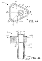
FIG. 4A is a top view of the tube assembly ofFIG. 3B . -
FIG. 4B is a sectional view ofsection 4B-4B ofFIG. 4A . -
FIG. 5 is a sectional view of section 5-5 ofFIG. 4A . -
FIG. 1 schematically illustrates examplegas turbine engine 10, which includesfan section 12,compressor section 14,combustor section 16,turbine section 18, andcowl 19.Fan section 12 drives air along bypass flow path B whilecompressor section 14 draws air in along core flow path C where air is compressed and delivered tocombustor section 16. Incombustor section 16, air is mixed with fuel and ignited to generate a high pressure exhaust gas stream that expands throughturbine section 18, where energy is extracted and utilized to drivefan section 12 andcompressor section 14. - Mid-turbine frame (MTF) 20 is arranged generally between
high pressure turbine 22 andlow pressure turbine 24 ofturbine section 18.Mid-turbine frame 20 is a static structure that further supports a bearing case inturbine section 18 as well as setting airflow enteringlow pressure turbine 24.Cowl 19 surrounds and enclosescompressor section 14,combustor section 16, andturbine section 18, includingMTF 20. -
FIG. 2 is an isometric view of bearingsupport 26 andtube assembly 28 and schematic view ofcowl 19. Bearingsupport 26 includes bearingsection 30,inner flange mount 32,inner flange bolts 34,outer flange mount 36,outer flange bolts 38, and bearingmount 40. Also shown inFIG. 2 is supply oil S and leaked oil L. - Bearing
support 26 mounts to an internal case of MTF 20 (shown inFIG. 1 ). This connection occurs atinner flange connection 32 andouter flange connection 36.Inner flange bolts 34 connectinner flange 32 to the internal case ofMTF 20. Similarly,outer flange bolts 36 connectouter flange 34 to the internal case ofMTF 20. These connections secure bearingsupport 26 and fix the position of bearingsupport 26 and its static components relative toMTF 20 andturbine engine 10. -
Tube assembly 28 is physically connected to bearingmount 40 of bearingsupport 26 and is secured to bearingmount 40 by bolts (shown in later FIGS.). An inner tube (shown in later FIGS.) oftube assembly 28 is connected to an oil intake connection at bearingmount 40. An outer tube (shown in later FIGS.) oftube assembly 28 is connected tocowl 19. - In one embodiment, supply oil S is supplied through the inner tube of
tube assembly 28 to an oil intake connection at bearingmount 40. Oil is then distributed within bearingsupport 26 to internal bearing components for lubricating and cooling purposes. If supply oil S leaks at the connection betweentube assembly 28 and bearingmount 40, leaked oil L will be collected and transmitted bytube assembly 28 tocowl 19. Leaked oil L can be transmitted using gravity as the only motivating force. Leaked oil L can also be motivated by pressure from supply oil S, can be motivated by a motivator, such a pump, or any combination of these. Atcowl 19, leaked oil L can be detected during inspection or maintenance through visual inspection. Detection of oil at this location indicates that a seal, tube, or other component in the oil supply system has failed. Detection of leaked oil provides safety benefits, preventing potential component failure, as discussed in later FIGS. -
FIG. 3A is an isometric view oftube assembly 28.FIG. 3B is an exploded isometric view oftube assembly 28.FIGS. 3A and 3B are discussed concurrently.Tube assembly 28 includes bearing fitting 42,heat shield 44, bearingcoupler 46,heat shield 48, case fitting 50, caseinner coupler 52, caseouter coupler 54,outer tube 56, inserts 58, bearing fittingouter seal 60, bearing fittinginner seal 62, andcase fitting seal 64. Bearing fitting 42 includesouter tube connection 66,inner tube connection 68, mounts 70, and bearingpad connection 72. - Case fitting 50 is mounted to an outer case of
MTF 20 with fasteners to securetube assembly 28 to MTF. Bearing fitting 42 is mounted to bearingmount 40 of bearingsupport 26, as shown inFIG. 2 . Bearing fitting 42 is mounted to bearingmount 40 by bolts (shown in later FIGS.), which secure bearing fitting 42 to bearingmount 40. More specifically, inserts 58 are inserted intomounts 70 and secured inmounts 70 by welding, brazing, press-fitting, or other securing process.Inserts 58 are threaded inserts for receiving a threaded bolt, but may be other female fasteners. Bolts can then pass through bearingmount 40 and intoinserts 58 to secure bearing fitting 42 to bearingmount 40. These two connectionssecure tube assembly 28 between bearingsupport 26 and an outer case ofMTF 20. - Bearing fitting
outer seal 60 is applied to a face of bearing fitting 42 in a channel (shown in later FIGS.). Bearing fittinginner seal 62 is also applied to the same face of bearing fitting 42, but surrounds and contacts bearingpad connection 72.Bearing coupler 46 connects toouter tube connection 66, whileinner tube connection 68 passes through bearingcoupler 46.Bearing coupler 46 can be welded, brazed, or otherwise fastened to bearing fitting 42 atouter tube connection 66. Bearing fitting 42 is composed of metal resistant to relatively high pressures and temperatures, such as titanium alloy, a stainless steel (or other steel) alloy, aluminum alloy, or a nickel alloy. -
Inner tube connection 68, which passes through bearingcoupler 46, connects to an inner tube (shown in later FIGS.). The inner tube can be brazed, welded, or otherwise fastened toinner tube connection 68.Bearing coupler 46 then connects toouter tube 56, part of which is visible inFIG. 3B underheat shield 48.Outer tube 56, which surrounds the inner tube, is also brazed, welded, or otherwise fastened to bearingcoupler 46.Heat shield 48, which surroundsouter tube 56, also connects to bearingcoupler 46. Heat shield can be brazed, welded, or otherwise fastened to bearingcoupler 46. - At the other end of
heat shield 48 near case fitting 50,heat shield 48 makes contact with caseouter coupler 54, howeverheat shield 48 does not connect to caseouter coupler 54.Outer tube 56 also connects, in a slip-fit connection type, to caseouter coupler 54 and is brazed, welded, or otherwise fastened to caseouter coupler 54. Caseinner coupler 52 extends through case fitting 50 and through caseouter coupler 54 where it connects in a slip-fit manner to the inner tube and is secured by brazing, welding, or other securing methods. Caseouter coupler 54 then is seated and connected to case fitting 50 with case fitting seal located at the connection between case fitting 50 andouter case coupler 54. Another set of inner and outer tubes can then be connected to caseinner coupler 52 and caseouter coupler 54. Alternatively, case outer coupler can be left open to the core compartment. - When all of the components of
tube assembly 28 are connected, two flow pathways are created. A primary flow pathway is created from the inside of caseinternal coupler 52 to the inner tube toinner tube connection 68 of bearing fitting 42. The flow path continues through bearing fitting 42 to bearingpad connection 72, where the primary flow can be supplied to bearingsupport 26. The primary flow is typically oil for lubrication and cooling of components within bearingsupport 26. - The second pathway begins at bearing fitting 42. Oil that is leaked and collected by bearing fitting 42 can be delivered to
outer tube connection 66 and passed to bearingcoupler 46.Bearing coupler 46 can deliver leaked oil toouter tube 56, which can transport the leaked oil tocase coupler 54.Case coupler 54 can deliver the leaked oil to another tube connected tocase coupler 54 or can deliver the leaked oil to the core compartment. -
FIG. 4A is a top view oftube assembly 28 showing only bearing fitting 42 oftube assembly 28.FIG. 4B is a sectional view ofsection 4B-4B oftube assembly 28.FIGS. 4A and 4B are discussed concurrently.Tube assembly 28 includes bearing fitting 42, bearingcoupler 46,heat shield 48,outer tube 56,inner tube 57, bearing fittingouter seal 60, and bearing fittinginner seal 62. Bearing fitting 42 includesouter tube connection 66,inner tube connection 68, mounts 70, bearingpad connection 72,supply port 74,diagnostic port 76,groove 78, and surfaces S1 and S2. -
Groove 78 is a groove or channel in surface S1 of bearing fitting 42.Groove 78 is located near the perimeter of surface S1 and surrounds mounts 70. Bearing fittingouter seal 60 is a c type seal, or a metallic seal having a c-shaped profile that seals upon compression, that lies in and is secured ingroove 78.Groove 78 can also be located inside mounts 70, so long asgroove 78 is radially outboard ofdiagnostic port 76. -
Bearing pad connection 72 is a cylindrical tube-like connection that protrudes perpendicularly from surface S1 of fitting 42. Surrounding bearingpad connection 72 is bearing fittinginner seal 62. Bearing fittinginner seal 62 is a c type seal that circumferentially surrounds bearingpad connection 72 while making contact with surface S1 of bearing fitting 42. In this embodiment, bearing fittinginner seal 62 passes over part ofdiagnostic port 76. -
Diagnostic port 76, which begins at surface S1 of bearing fitting 42, passes through bearing fitting 42 and connects toouter tube connection 66. Similarly,supply port 74 passes through bearing fitting 42 from bearingpad connection 72 intoinner tube connection 66, where it meetsinner tube 57. -
Inner tube connection 68, which passes through bearingcoupler 46, connects toinner tube 57.Inner tube 57 can be brazed, welded, or otherwise fastened toinner tube connection 68.Bearing coupler 46 connects to bearing fitting 42 atouter tube connection 66.Bearing coupler 46 then connects toouter tube 56.Outer tube 56 is also brazed, welded, or otherwise fastened to bearingcoupler 46.Heat shield 48 also connects to bearingcoupler 46, as described above. - In one embodiment, these connections create a primary flow path. The primary flow pathway is from
inner tube 57 toinner tube connection 68 of bearing fitting 42. The flow path continues through bearing fitting 42 to bearingpad connection 72, where the primary flow can be supplied to bearingsupport 26. The primary flow is typically oil for lubrication and cooling of components within bearingsupport 26. - Oil is an essential lubricant and coolant in aviation applications; however, oil presents a danger as it is a flammable fluid. Turbine engines often operate at temperatures higher than the flash temperature of oil. To combat this safety issue, double-wall tubes are used to contain oil leaks. Inner tubes carry supply oil and outer tubes carry leaked oil. While double-wall tubes provide leak prevention, they present difficulties in manufacturing, assembly, and detection of leaked oil.
- This disclosure addresses these problems.
Tube assembly 28 creates a second flow path for leaked oil. The second pathway begins at bearing fitting 42. Oil can be leaked around mounts 70 or around bearingpad connection 72 and bearing fittinginner seal 62. This leaked oil will be held within surface S1 of bearing fitting 42 by bearing fittingouter seal 60. Leaked oil L is then collected bydiagnostic port 76 and can be delivered through bearing fitting 42 toouter tube connection 66 and passed to bearingcoupler 46.Bearing coupler 46 can deliver leaked oil L toouter tube 56, which can transport leaked oil L to case coupler 54 (ofFIGS. 3A and 3B ).Case coupler 54 can deliver leaked oil L to another tube connected tocase coupler 54 or case fitting 50, ultimately delivering leaked oil L to a location where it can be easily detected, such ascowling 19, as described inFIG. 2 . - Bearing fitting 42 offers a dual seal against oil leaks at bearing
pad connection 72. Bearing fittinginner seal 62 operates as a first seal and bearing fittingouter seal 60 operates as a second seal. The dual sealing of bearing fitting 42 against bearing mount 40 functions as a redundant sealing of bearing fitting 42, which is desirable to prevent leaks where more permanent connections (such as brazing and welding) cannot be used, because of service and manufacturing constraints. Further, having multiple seals allows fordiagnostic port 76 to detect leaks before both seals are compromised. When bearing fittinginner seal 62 leaks oil,diagnostic port 76 will transport the leaked oil to a detectible location, as described above. This allows for leaked oil L to be detected before bearing fittingouter seal 60 is compromised. - In this embodiment,
diagnostic port 76 is located under bearing fittinginner seal 62. In other words, bearing fittinginner seal 62 passes partially overdiagnostic port 76. This allows oil that leaks around bearing fittinginner seal 62 to be more easily communicated todiagnostic port 76.Diagnostic port 76 may also gather oil leaked from other components, for example from bearingmount 40. -
Diagnostic port 76 is designed to have a hydraulic diameter (DH) that is greater than the surface tension and capillary forces created by the diagnostic port acting on leaked oil L. Further, the DH ofdiagnostic port 76 is designed to overcome surface tension and capillary forces by flow of small amounts of leaked oil L, such as 1 mL of leaked oil. -
Outer tube 56 andinner tube 57 are tubes or pipes for transporting pressurized fluid.Outer tube 56 andinner tube 57 are comprised of stainless steel, aluminum alloy, nickel alloy, titanium, or any other material suitable for transporting high temperature oils. - Bearing fitting
outer seal 60 and bearing fittinginner seal 62 are metallic c type seals. However, other seal types may be used, such as a chevron seal. Bearing fittingouter seal 60 and bearing fittinginner seal 62 are metal c type seals, but can be made from elastomeric or energized Polytetrafluoroethylene (PTFE) materials. -
FIG. 5 is a sectional view of section 5-5 of another embodiment of bearingtube assembly 28 ofFIG. 4A .Tube assembly 28 includes bearing fitting 42a, bearingcoupler 46,heat shield 48,outer tube 56,inner tube 57, bearing fittingouter seal 60, bearing fittinginner seal 62, andbolts 82. Bearing fitting 42 includesouter tube connection 66,inner tube connection 68, mounts 70, bearingpad connection 72,supply port 74, diagnostic port 76a,groove 78, andtrench 80.Bearing mount 40 includesnotch 84. Also shown inFIG. 5 are surface S1, surface S2, supply oil S and leaked oil L. - The components of bearing fitting 42a are connected consistently with previous FIGS.; however,
FIG. 5 further details the connection of bearing fitting 42a to bearingmount 40. Bearing fitting 42a is connected to bearingmount 40 bybolts 82, which pass through bearingmount 40, intomounts 70, and intoinserts 58, to whichbolts 82 are fastened. The connection between fitting 42a and bearing mount 40 draws fitting 42a to contact the surface of bearingmount 40. Further, bearing fittingouter seal 60, which resides ingroove 78, is contacted by bearingmount 40, compressing bearing fittingouter seal 60 between bearingmount 40 and bearing fitting 42. Similarly, bearing fitting inner seal, which resides ingroove 78, is contacted and by bearingmount 40, compressing bearing fittinginner seal 62 between bearingmount 40 and bearing fitting 42. In bearingmount 40notch 84, which may be a groove or channel in bearingmount 40, is located just above bearing fittinginner seal 62.Notch 84 is physically sized to apply sufficient pressure on bearing fittinginner seal 62 to create a seal between bearing fitting 42a and bearingmount 40.Groove 78, and the surface of bearingmount 40 contacting and compressing bearing fittingouter seal 60 also apply sufficient pressure on bearing fittingouter seal 60 to create a seal between bearing fitting 42a and bearing mount 40 atouter seal 60. - In this embodiment, bearing fitting 42a differs from previous embodiments in some ways. One difference is that bearing fitting 42a includes
trench 80.Trench 80 is a trench or channel in the surface of bearing fitting 42a between bearingpad connection 72 and diagnostic port 76a.Trench 80 connects to diagnostic port 76a. Diagnostic port 76a is angled through bearing fitting 42a, in this embodiment, before connecting toouter tube connection 66. -
Trench 80 allows for oil that is leaked around bearing fittinginner seal 62 to be more easily communicated to diagnostic port 76a when diagnostic port 76a is not located directly underneath a portion of bearing fittinginner seal 62 ornotch 84.Trench 80 also allows for easier machining of diagnostic port 76a, becausenotch 84 allows for the beginning of diagnostic port 76a to be located further away from bearingpad connection 72 and therefore farther from a fillet or chamfer between bearingpad connection 72 and surface S1. This allows for a simpler drilling process, because the drilling surface at surface S1 is more likely to be flat. Also, with diagnostic port 76a being spaced away from bearingpad connection 72 and therefore supplyport 74, it is less likely that a cutting tool used to create diagnostic port 76a will penetrate intosupply port 74, reducing machining errors and saving time and material. - Though
tube assembly 28 has been described to operate in conjunction with anMTF 20,tube assembly 28 and bearing fitting 42 can be applied to any system within an aircraft where double wall tubes may be required. Further, thoughtube assembly 28 has been described as being a component of an aircraft,tube assembly 28 could be used in any application where double wall tubes are required, such as automotive or process management applications. Additionally, thoughtube assembly 28 is described as transporting supply and leaked oil,tube assembly 28 can transport any fluid. - The following are non-exclusive descriptions of possible embodiments of the present invention.
- In one embodiment, a fitting for attaching to double wall tubes includes a body, a fitting center port, an outer seal, a tube connection, a pad connection, an inner seal, a groove, and a diagnostic port. The body has a first surface on a first side of the body and a second surface on a second side of the body. The fitting center port extends through the body for passing a primary fluid flow. The tube connection is on the first side of the fitting, and includes an inner connection and an outer connection. The inner connection protrudes from the first surface, and the inner connection surrounds the center port and is for attaching an inner tube. The outer connection protrudes from the first surface, and surrounds the inner connection for attaching an outer tube. The pad connection extends from the second surface of the fitting, surrounds the center port, and is for connecting to a mounting pad. The inner seal surrounds the pad connection and is adjacent to the second surface of the fitting. The groove is in the second surface surrounding the inner seal and the groove is configured to receive an outer seal. The diagnostic port is in the second surface for transferring a collected fluid through the body to the outer connection.
- The fitting of the preceding paragraph can optionally include, additionally and/or alternatively, any one or more of the following features, configurations and/or additional components.
- A plurality of fitting mounts can be spaced radially away from the center port on the second side of the body for receiving fasteners, where the outer seal can circumscribe the fitting mounts.
- A trench in the second surface of the fitting can be located between the diagnostic port and the pad connection.
- The inner seal can pass over part of the diagnostic port.
- The fitting can have a shape of a rounded triangular prism.
- The fitting body can be formed of a single piece.
- The fitting material can be one of a titanium alloy, a stainless steel alloy, aluminum ally, or a nickel alloy.
- The diagnostic port can have a hydraulic diameter sized so that surface tension and capillary forces created by the diagnostic port acting on a leaked fluid can be overcome by flow of small amounts of leaked fluid.
- The inner seal and outer seal can be c type seals.
- In another embodiment, a double wall tube assembly for distributing a pressurized fluid includes a fitting, an inner tube, an outer tube, and a mounting pad. The fitting attaches to double wall tubes and includes a body, a fitting center port, an outer seal, a tube connection, a pad connection, an inner seal, a groove, and a diagnostic port. The body has a first surface on a first side of the body and a second surface on a second side of the body. The fitting center port extends through the body for passing a primary fluid flow. The tube connection is on the first side of the fitting, and includes an inner connection and an outer connection. The inner connection protrudes from the first surface and surrounds the center port. The outer connection protrudes from the first surface and surrounds the inner connection. The pad connection extends from the second surface of the fitting and surrounds the center port. The inner seal surrounds the pad connection and is adjacent to the second surface of the fitting. The groove is in the second surface, surrounding the inner seal and is configured to receive an outer seal. The diagnostic port is in the second surface for transferring a collected fluid through the body to the outer connection. The inner tube is connected to the inner connection and the outer tube is connected to the outer connection and surrounds the inner tube. The mounting pad is for mounting to the second surface of the fitting, and includes a fluid inlet for receiving a primary fluid flow from the fitting.
- The assembly of the preceding paragraph can optionally include, additionally and/or alternatively, any one or more of the following features, configurations and/or additional components.
- A heat shield can surround the fitting.
- A plurality of fitting mounts can be spaced radially away from the center port on the second side of the fitting for receiving a plurality of fasteners and for mounting the fitting to the mounting pad.
- The inner seal and the outer seal can be c type seals.
- A trench can be in the second surface of the fitting between the diagnostic port and the pad connection.
- The inner seal can pass over part of the diagnostic port.
- Another embodiment includes a method for distributing leaked fluid for visual leak detection. The method includes passing a pressurized fluid from an inner tube through a fitting. A leaked fluid is collected at a diagnostic port on a first side of the fitting. The leaked fluid is passed from the diagnostic port to an outer tube connected to a second side of the fitting. The leaked fluid is transmitted to a location for visual detection.
- The method of the preceding paragraph can optionally include, additionally and/or alternatively, any one or more of the following features, configurations and/or additional components, or steps.
- The leaked fluid can be distributed using only gravity as a motivating force to a location for visual detection.
- The visual detecting location can be at a cowl of a turbine engine.
- The pressurized fluid can be leaked around an inner seal on the first side of the fitting.
- The pressurized fluid can be leaked around an outer seal on the first side of the fitting.
- While the invention has been described with reference to an exemplary embodiment(s), it will be understood by those skilled in the art that various changes may be made without departing from the scope of the invention. In addition, many modifications may be made to adapt a particular situation or material to the teachings of the invention without departing from the essential scope thereof. Therefore, it is intended that the invention not be limited to the particular embodiment(s) disclosed, but that the invention will include all embodiments falling within the scope of the appended claims.
Claims (15)
- A fitting (42) for attaching to double wall tubes, the fitting comprising:a body having a first surface on a first side of the body and a second surface on a second side of the body;a fitting center port extending through the body for passing a primary fluid flow;a tube connection on the first side of the fitting, the connection comprising:an inner connection protruding from the first surface, wherein the inner connection surrounds the center port for attaching an inner tube; andan outer connection protruding from the first surface, wherein the outer connection surrounds the inner connection for attaching an outer tube;a pad connection (72) extending from the second surface of the fitting, wherein the pad connection surrounds the center port and connects to a mounting pad;an inner seal (62) surrounding the pad connection (72) and adjacent to the second surface of the fitting;a groove (78) in the second surface surrounding the inner connection, wherein the groove is configured to receive an outer seal (60); anda diagnostic port (76) in the second surface for transferring a collected fluid through the body to the outer connection.
- The fitting of claim 1 and further comprising a plurality of fitting mounts spaced radially away from the center port on the second side of the body for receiving fasteners, wherein the outer seal circumscribes the fitting mounts.
- The fitting of claims 1 or 2and further comprising a trench in the second surface of the fitting located between the diagnostic port (76) and the pad connection (72).
- The fitting of any preceding claim, wherein the inner seal passes over part of the diagnostic port (76).
- The fitting of any preceding claim, wherein the fitting (42) has a shape of a rounded triangular prism.
- The fitting of any preceding claim, wherein the fitting body is formed of a single piece.
- The fitting of any preceding claim, wherein the fitting material is one of a titanium alloy, a stainless steel alloy, aluminum alloy, or a nickel alloy.
- The fitting of any preceding claim, wherein the diagnostic port (76) has a hydraulic diameter sized so that surface tension and capillary forces created by the diagnostic port (76) acting on a leaked fluid are overcome by flow of small amounts of leaked fluid.
- The fitting of any preceding claim, wherein the inner seal 62) and outer seal (60) are c type seals.
- The double wall tube assembly of any preceding claim and further comprising a heat shield (48) surrounding the fitting.
- A method of distributing leaked fluid for visual leak detection, comprising:passing a pressurized fluid from an inner tube through a fitting (42);collecting a leaked fluid at a diagnostic port (76) on a first side of the fitting;passing leaked fluid from the diagnostic port (76) to an outer tube connected to a second side of the fitting; andtransmitting the leaked fluid to a location for visual detection.
- The method of claim 11, wherein the leaked fluid is distributed using only gravity as a motivating force to a location for visual detection.
- The method of claim 12, wherein the visual detecting location is at a cowl of a turbine engine.
- The method of any of claims 11-13, wherein the pressurized fluid is leaked around an inner seal (62) on the first side of the fitting.
- The method of any of claims 11-13, wherein the pressurized fluid is leaked around an outer seal (60) on the first side of the fitting.
Applications Claiming Priority (1)
| Application Number | Priority Date | Filing Date | Title |
|---|---|---|---|
| US14/671,101 US10066774B2 (en) | 2015-03-27 | 2015-03-27 | Double wall tube fitting with an integrated diagnostic port |
Publications (2)
| Publication Number | Publication Date |
|---|---|
| EP3073168A1 true EP3073168A1 (en) | 2016-09-28 |
| EP3073168B1 EP3073168B1 (en) | 2018-09-12 |
Family
ID=55628931
Family Applications (1)
| Application Number | Title | Priority Date | Filing Date |
|---|---|---|---|
| EP16162334.3A Active EP3073168B1 (en) | 2015-03-27 | 2016-03-24 | Double wall tube fitting with an integrated diagnostic port |
Country Status (2)
| Country | Link |
|---|---|
| US (1) | US10066774B2 (en) |
| EP (1) | EP3073168B1 (en) |
Families Citing this family (2)
| Publication number | Priority date | Publication date | Assignee | Title |
|---|---|---|---|---|
| US11149640B2 (en) * | 2019-09-13 | 2021-10-19 | Raytheon Technologies Corporation | Circular seal outer diameter seal effectiveness testing tool |
| FR3122469B1 (en) * | 2021-04-30 | 2023-04-14 | A Raymond Et Cie | Connector |
Citations (3)
| Publication number | Priority date | Publication date | Assignee | Title |
|---|---|---|---|---|
| US4723441A (en) * | 1985-11-07 | 1988-02-09 | Ply-Flow Engineering, Inc. | Piping system for hazardous fluids |
| EP1229290A2 (en) * | 2001-02-05 | 2002-08-07 | General Electric Company | Afterburner heat shield |
| US20040026922A1 (en) * | 2002-08-09 | 2004-02-12 | Carns James A. | Shrouded fluid-conducting apparatus |
Family Cites Families (23)
| Publication number | Priority date | Publication date | Assignee | Title |
|---|---|---|---|---|
| US3046026A (en) * | 1958-10-22 | 1962-07-24 | Manning Maxwell & Moore Inc | High pressure seal |
| US3233927A (en) | 1963-03-28 | 1966-02-08 | Lee T Dewhirst | Conduit means |
| US4445332A (en) * | 1982-03-24 | 1984-05-01 | Caterpillar Tractor Co. | Hydraulic hose assembly and method |
| EP0268251B1 (en) | 1986-11-18 | 1990-12-27 | Smc Corporation | Tube joint for use with multi-walled tube assembly |
| US5199747A (en) | 1991-05-16 | 1993-04-06 | Jahr Willi E | Connector assembly for double walled tubing |
| US5494318A (en) | 1993-04-29 | 1996-02-27 | Butts; Nicholas E. | Secondary containment system |
| NO310585B1 (en) | 1998-03-25 | 2001-07-23 | Reslink As | Pipe connection for connection of double walled pipes |
| IT244388Y1 (en) | 1998-11-23 | 2002-03-11 | Nupi S P A | FITTINGS FOR DOUBLE WALL PIPES |
| FR2804197B1 (en) | 2000-01-24 | 2002-07-12 | Coflexip | LIMITING DEVICE FOR THE PROPAGATION OF A DEFORMATION IN A DOUBLE WALL PIPE FOR LARGE DEPTHS |
| DE10044336A1 (en) | 2000-09-07 | 2002-03-21 | Uhde Hochdrucktechnik Gmbh | Flange connection for high pressure double jacket pipes |
| DE10064227C1 (en) | 2000-12-22 | 2002-06-20 | Airbus Gmbh | Connecting device for two double-wall tube lines has fixing body fixed to inner tube outer wall of first inner tube line close to inner tube line's coupled end |
| US6886388B1 (en) | 2002-04-24 | 2005-05-03 | Mcgill M. Daniel | Contiguous double containment underground storage tank fueling system and methods for detecting leaks therein |
| US6854487B2 (en) | 2003-06-26 | 2005-02-15 | General Electric Company | Fluid conduit wall inhibiting heat transfer and method for making |
| KR100590619B1 (en) | 2004-08-05 | 2006-06-19 | 이보영 | Heat Plate for welding the pipe with multi-walls and the method for welding the same |
| GB0523573D0 (en) | 2005-11-18 | 2005-12-28 | Airbus Uk Ltd | Aircraft fuel pipe coupling |
| US8122721B2 (en) * | 2006-01-04 | 2012-02-28 | General Electric Company | Combustion turbine engine and methods of assembly |
| DE102007051436B4 (en) | 2007-10-25 | 2010-01-28 | H. Butting Gmbh & Co. Kg | Connection system for double-walled pipes |
| US7942452B2 (en) * | 2007-11-20 | 2011-05-17 | The Boeing Company | Flange fitting with leak sensor port |
| DE102009052674B4 (en) | 2009-11-12 | 2012-10-18 | Karl Weinhold | Method and device for connecting double-walled pipes |
| DE102011010385A1 (en) | 2011-02-05 | 2012-08-09 | Eads Deutschland Gmbh | Double-walled pipe and manufacturing process |
| WO2013086191A1 (en) * | 2011-12-07 | 2013-06-13 | Polyflow Llc | Pipe system with annulus utilization and monitoring |
| US8820794B1 (en) * | 2012-07-05 | 2014-09-02 | James C. Betz | Hose-in-hose coupler |
| US9605633B2 (en) * | 2014-04-30 | 2017-03-28 | Electro-Motive Diesel, Inc. | Manifold assembly for dual-walled pipe |
-
2015
- 2015-03-27 US US14/671,101 patent/US10066774B2/en active Active
-
2016
- 2016-03-24 EP EP16162334.3A patent/EP3073168B1/en active Active
Patent Citations (3)
| Publication number | Priority date | Publication date | Assignee | Title |
|---|---|---|---|---|
| US4723441A (en) * | 1985-11-07 | 1988-02-09 | Ply-Flow Engineering, Inc. | Piping system for hazardous fluids |
| EP1229290A2 (en) * | 2001-02-05 | 2002-08-07 | General Electric Company | Afterburner heat shield |
| US20040026922A1 (en) * | 2002-08-09 | 2004-02-12 | Carns James A. | Shrouded fluid-conducting apparatus |
Also Published As
| Publication number | Publication date |
|---|---|
| US10066774B2 (en) | 2018-09-04 |
| EP3073168B1 (en) | 2018-09-12 |
| US20160281896A1 (en) | 2016-09-29 |
Similar Documents
| Publication | Publication Date | Title |
|---|---|---|
| US8231142B2 (en) | Fluid conduit coupling with leakage detection | |
| EP2957805B1 (en) | Bolted flange fitting assembly for double wall tube | |
| EP2042691A2 (en) | Lubricant pipe assembly for a turbine | |
| US7568843B2 (en) | Oil bearing and tube assembly concept | |
| US5890746A (en) | Cooled and wetted redundant seal tube fitting | |
| EP3358139B1 (en) | Threaded fitting for tube | |
| US20150369400A1 (en) | Double wall tube assemblies | |
| EP2896862B1 (en) | Fastener, corresponding fastener assembly and gas turbine | |
| EP3073168B1 (en) | Double wall tube fitting with an integrated diagnostic port | |
| EP1144894B1 (en) | Secured coupling assembly and method of preventing loosening | |
| EP2434190B1 (en) | Refrigeration system connection fitting | |
| US9683458B2 (en) | Oil scupper system for bearing housing of gas turbine engine | |
| EP3746691B1 (en) | A flange assembly | |
| US7870655B2 (en) | Process of endforming a tubular assembly | |
| EP3992434A1 (en) | Service tube assembly for a gas turbine engine | |
| GB2491886A (en) | A Turbocharger Conduit Connector | |
| US11149640B2 (en) | Circular seal outer diameter seal effectiveness testing tool | |
| US10619549B2 (en) | Lobed exhaust manifold slip joint | |
| CN115370971A (en) | Coupling for vacuum insulated pipes | |
| US20160238480A1 (en) | Seal vacuum check tool | |
| US20170268685A1 (en) | Compressor thermal valve unit to route lubricant used in a compressor | |
| US20110031067A1 (en) | Turbocharger Lubrication Feed Adapter | |
| CN203500712U (en) | Sealing component and motor vehicle |
Legal Events
| Date | Code | Title | Description |
|---|---|---|---|
| PUAI | Public reference made under article 153(3) epc to a published international application that has entered the european phase |
Free format text: ORIGINAL CODE: 0009012 |
|
| AK | Designated contracting states |
Kind code of ref document: A1 Designated state(s): AL AT BE BG CH CY CZ DE DK EE ES FI FR GB GR HR HU IE IS IT LI LT LU LV MC MK MT NL NO PL PT RO RS SE SI SK SM TR |
|
| AX | Request for extension of the european patent |
Extension state: BA ME |
|
| RAP1 | Party data changed (applicant data changed or rights of an application transferred) |
Owner name: UNITED TECHNOLOGIES CORPORATION |
|
| STAA | Information on the status of an ep patent application or granted ep patent |
Free format text: STATUS: REQUEST FOR EXAMINATION WAS MADE |
|
| 17P | Request for examination filed |
Effective date: 20170315 |
|
| RBV | Designated contracting states (corrected) |
Designated state(s): AL AT BE BG CH CY CZ DE DK EE ES FI FR GB GR HR HU IE IS IT LI LT LU LV MC MK MT NL NO PL PT RO RS SE SI SK SM TR |
|
| RIC1 | Information provided on ipc code assigned before grant |
Ipc: F16L 23/16 20060101ALI20180301BHEP Ipc: F01D 25/28 20060101ALI20180301BHEP Ipc: F17D 5/02 20060101ALI20180301BHEP Ipc: F01D 25/00 20060101ALI20180301BHEP Ipc: F16L 39/02 20060101ALI20180301BHEP Ipc: B64G 1/00 20060101ALI20180301BHEP Ipc: F02C 7/00 20060101ALI20180301BHEP Ipc: F16L 39/00 20060101AFI20180301BHEP Ipc: G01M 3/28 20060101ALI20180301BHEP Ipc: F16L 17/08 20060101ALI20180301BHEP Ipc: G01M 3/00 20060101ALI20180301BHEP |
|
| GRAP | Despatch of communication of intention to grant a patent |
Free format text: ORIGINAL CODE: EPIDOSNIGR1 |
|
| STAA | Information on the status of an ep patent application or granted ep patent |
Free format text: STATUS: GRANT OF PATENT IS INTENDED |
|
| INTG | Intention to grant announced |
Effective date: 20180413 |
|
| GRAS | Grant fee paid |
Free format text: ORIGINAL CODE: EPIDOSNIGR3 |
|
| GRAA | (expected) grant |
Free format text: ORIGINAL CODE: 0009210 |
|
| STAA | Information on the status of an ep patent application or granted ep patent |
Free format text: STATUS: THE PATENT HAS BEEN GRANTED |
|
| AK | Designated contracting states |
Kind code of ref document: B1 Designated state(s): AL AT BE BG CH CY CZ DE DK EE ES FI FR GB GR HR HU IE IS IT LI LT LU LV MC MK MT NL NO PL PT RO RS SE SI SK SM TR |
|
| REG | Reference to a national code |
Ref country code: GB Ref legal event code: FG4D |
|
| REG | Reference to a national code |
Ref country code: CH Ref legal event code: EP |
|
| REG | Reference to a national code |
Ref country code: IE Ref legal event code: FG4D |
|
| REG | Reference to a national code |
Ref country code: DE Ref legal event code: R096 Ref document number: 602016005430 Country of ref document: DE |
|
| REG | Reference to a national code |
Ref country code: AT Ref legal event code: REF Ref document number: 1041010 Country of ref document: AT Kind code of ref document: T Effective date: 20181015 |
|
| REG | Reference to a national code |
Ref country code: NL Ref legal event code: MP Effective date: 20180912 |
|
| REG | Reference to a national code |
Ref country code: LT Ref legal event code: MG4D |
|
| PG25 | Lapsed in a contracting state [announced via postgrant information from national office to epo] |
Ref country code: FI Free format text: LAPSE BECAUSE OF FAILURE TO SUBMIT A TRANSLATION OF THE DESCRIPTION OR TO PAY THE FEE WITHIN THE PRESCRIBED TIME-LIMIT Effective date: 20180912 Ref country code: LT Free format text: LAPSE BECAUSE OF FAILURE TO SUBMIT A TRANSLATION OF THE DESCRIPTION OR TO PAY THE FEE WITHIN THE PRESCRIBED TIME-LIMIT Effective date: 20180912 Ref country code: BG Free format text: LAPSE BECAUSE OF FAILURE TO SUBMIT A TRANSLATION OF THE DESCRIPTION OR TO PAY THE FEE WITHIN THE PRESCRIBED TIME-LIMIT Effective date: 20181212 Ref country code: SE Free format text: LAPSE BECAUSE OF FAILURE TO SUBMIT A TRANSLATION OF THE DESCRIPTION OR TO PAY THE FEE WITHIN THE PRESCRIBED TIME-LIMIT Effective date: 20180912 Ref country code: NO Free format text: LAPSE BECAUSE OF FAILURE TO SUBMIT A TRANSLATION OF THE DESCRIPTION OR TO PAY THE FEE WITHIN THE PRESCRIBED TIME-LIMIT Effective date: 20181212 Ref country code: RS Free format text: LAPSE BECAUSE OF FAILURE TO SUBMIT A TRANSLATION OF THE DESCRIPTION OR TO PAY THE FEE WITHIN THE PRESCRIBED TIME-LIMIT Effective date: 20180912 Ref country code: GR Free format text: LAPSE BECAUSE OF FAILURE TO SUBMIT A TRANSLATION OF THE DESCRIPTION OR TO PAY THE FEE WITHIN THE PRESCRIBED TIME-LIMIT Effective date: 20181213 |
|
| PG25 | Lapsed in a contracting state [announced via postgrant information from national office to epo] |
Ref country code: HR Free format text: LAPSE BECAUSE OF FAILURE TO SUBMIT A TRANSLATION OF THE DESCRIPTION OR TO PAY THE FEE WITHIN THE PRESCRIBED TIME-LIMIT Effective date: 20180912 Ref country code: AL Free format text: LAPSE BECAUSE OF FAILURE TO SUBMIT A TRANSLATION OF THE DESCRIPTION OR TO PAY THE FEE WITHIN THE PRESCRIBED TIME-LIMIT Effective date: 20180912 Ref country code: LV Free format text: LAPSE BECAUSE OF FAILURE TO SUBMIT A TRANSLATION OF THE DESCRIPTION OR TO PAY THE FEE WITHIN THE PRESCRIBED TIME-LIMIT Effective date: 20180912 |
|
| REG | Reference to a national code |
Ref country code: AT Ref legal event code: MK05 Ref document number: 1041010 Country of ref document: AT Kind code of ref document: T Effective date: 20180912 |
|
| PG25 | Lapsed in a contracting state [announced via postgrant information from national office to epo] |
Ref country code: CZ Free format text: LAPSE BECAUSE OF FAILURE TO SUBMIT A TRANSLATION OF THE DESCRIPTION OR TO PAY THE FEE WITHIN THE PRESCRIBED TIME-LIMIT Effective date: 20180912 Ref country code: RO Free format text: LAPSE BECAUSE OF FAILURE TO SUBMIT A TRANSLATION OF THE DESCRIPTION OR TO PAY THE FEE WITHIN THE PRESCRIBED TIME-LIMIT Effective date: 20180912 Ref country code: AT Free format text: LAPSE BECAUSE OF FAILURE TO SUBMIT A TRANSLATION OF THE DESCRIPTION OR TO PAY THE FEE WITHIN THE PRESCRIBED TIME-LIMIT Effective date: 20180912 Ref country code: IT Free format text: LAPSE BECAUSE OF FAILURE TO SUBMIT A TRANSLATION OF THE DESCRIPTION OR TO PAY THE FEE WITHIN THE PRESCRIBED TIME-LIMIT Effective date: 20180912 Ref country code: EE Free format text: LAPSE BECAUSE OF FAILURE TO SUBMIT A TRANSLATION OF THE DESCRIPTION OR TO PAY THE FEE WITHIN THE PRESCRIBED TIME-LIMIT Effective date: 20180912 Ref country code: NL Free format text: LAPSE BECAUSE OF FAILURE TO SUBMIT A TRANSLATION OF THE DESCRIPTION OR TO PAY THE FEE WITHIN THE PRESCRIBED TIME-LIMIT Effective date: 20180912 Ref country code: IS Free format text: LAPSE BECAUSE OF FAILURE TO SUBMIT A TRANSLATION OF THE DESCRIPTION OR TO PAY THE FEE WITHIN THE PRESCRIBED TIME-LIMIT Effective date: 20190112 Ref country code: ES Free format text: LAPSE BECAUSE OF FAILURE TO SUBMIT A TRANSLATION OF THE DESCRIPTION OR TO PAY THE FEE WITHIN THE PRESCRIBED TIME-LIMIT Effective date: 20180912 Ref country code: PL Free format text: LAPSE BECAUSE OF FAILURE TO SUBMIT A TRANSLATION OF THE DESCRIPTION OR TO PAY THE FEE WITHIN THE PRESCRIBED TIME-LIMIT Effective date: 20180912 |
|
| PG25 | Lapsed in a contracting state [announced via postgrant information from national office to epo] |
Ref country code: PT Free format text: LAPSE BECAUSE OF FAILURE TO SUBMIT A TRANSLATION OF THE DESCRIPTION OR TO PAY THE FEE WITHIN THE PRESCRIBED TIME-LIMIT Effective date: 20190112 Ref country code: SK Free format text: LAPSE BECAUSE OF FAILURE TO SUBMIT A TRANSLATION OF THE DESCRIPTION OR TO PAY THE FEE WITHIN THE PRESCRIBED TIME-LIMIT Effective date: 20180912 Ref country code: SM Free format text: LAPSE BECAUSE OF FAILURE TO SUBMIT A TRANSLATION OF THE DESCRIPTION OR TO PAY THE FEE WITHIN THE PRESCRIBED TIME-LIMIT Effective date: 20180912 |
|
| REG | Reference to a national code |
Ref country code: DE Ref legal event code: R097 Ref document number: 602016005430 Country of ref document: DE |
|
| PLBE | No opposition filed within time limit |
Free format text: ORIGINAL CODE: 0009261 |
|
| STAA | Information on the status of an ep patent application or granted ep patent |
Free format text: STATUS: NO OPPOSITION FILED WITHIN TIME LIMIT |
|
| PG25 | Lapsed in a contracting state [announced via postgrant information from national office to epo] |
Ref country code: DK Free format text: LAPSE BECAUSE OF FAILURE TO SUBMIT A TRANSLATION OF THE DESCRIPTION OR TO PAY THE FEE WITHIN THE PRESCRIBED TIME-LIMIT Effective date: 20180912 |
|
| 26N | No opposition filed |
Effective date: 20190613 |
|
| PG25 | Lapsed in a contracting state [announced via postgrant information from national office to epo] |
Ref country code: SI Free format text: LAPSE BECAUSE OF FAILURE TO SUBMIT A TRANSLATION OF THE DESCRIPTION OR TO PAY THE FEE WITHIN THE PRESCRIBED TIME-LIMIT Effective date: 20180912 |
|
| PG25 | Lapsed in a contracting state [announced via postgrant information from national office to epo] |
Ref country code: MC Free format text: LAPSE BECAUSE OF FAILURE TO SUBMIT A TRANSLATION OF THE DESCRIPTION OR TO PAY THE FEE WITHIN THE PRESCRIBED TIME-LIMIT Effective date: 20180912 |
|
| REG | Reference to a national code |
Ref country code: CH Ref legal event code: PL |
|
| PG25 | Lapsed in a contracting state [announced via postgrant information from national office to epo] |
Ref country code: LU Free format text: LAPSE BECAUSE OF NON-PAYMENT OF DUE FEES Effective date: 20190324 |
|
| REG | Reference to a national code |
Ref country code: BE Ref legal event code: MM Effective date: 20190331 |
|
| PG25 | Lapsed in a contracting state [announced via postgrant information from national office to epo] |
Ref country code: CH Free format text: LAPSE BECAUSE OF NON-PAYMENT OF DUE FEES Effective date: 20190331 Ref country code: LI Free format text: LAPSE BECAUSE OF NON-PAYMENT OF DUE FEES Effective date: 20190331 Ref country code: IE Free format text: LAPSE BECAUSE OF NON-PAYMENT OF DUE FEES Effective date: 20190324 |
|
| PG25 | Lapsed in a contracting state [announced via postgrant information from national office to epo] |
Ref country code: BE Free format text: LAPSE BECAUSE OF NON-PAYMENT OF DUE FEES Effective date: 20190331 |
|
| PG25 | Lapsed in a contracting state [announced via postgrant information from national office to epo] |
Ref country code: TR Free format text: LAPSE BECAUSE OF FAILURE TO SUBMIT A TRANSLATION OF THE DESCRIPTION OR TO PAY THE FEE WITHIN THE PRESCRIBED TIME-LIMIT Effective date: 20180912 |
|
| PG25 | Lapsed in a contracting state [announced via postgrant information from national office to epo] |
Ref country code: MT Free format text: LAPSE BECAUSE OF NON-PAYMENT OF DUE FEES Effective date: 20190324 |
|
| PG25 | Lapsed in a contracting state [announced via postgrant information from national office to epo] |
Ref country code: CY Free format text: LAPSE BECAUSE OF FAILURE TO SUBMIT A TRANSLATION OF THE DESCRIPTION OR TO PAY THE FEE WITHIN THE PRESCRIBED TIME-LIMIT Effective date: 20180912 |
|
| PG25 | Lapsed in a contracting state [announced via postgrant information from national office to epo] |
Ref country code: HU Free format text: LAPSE BECAUSE OF FAILURE TO SUBMIT A TRANSLATION OF THE DESCRIPTION OR TO PAY THE FEE WITHIN THE PRESCRIBED TIME-LIMIT; INVALID AB INITIO Effective date: 20160324 |
|
| PG25 | Lapsed in a contracting state [announced via postgrant information from national office to epo] |
Ref country code: MK Free format text: LAPSE BECAUSE OF FAILURE TO SUBMIT A TRANSLATION OF THE DESCRIPTION OR TO PAY THE FEE WITHIN THE PRESCRIBED TIME-LIMIT Effective date: 20180912 |
|
| REG | Reference to a national code |
Ref country code: DE Ref legal event code: R081 Ref document number: 602016005430 Country of ref document: DE Owner name: RAYTHEON TECHNOLOGIES CORPORATION (N.D.GES.D.S, US Free format text: FORMER OWNER: UNITED TECHNOLOGIES CORPORATION, FARMINGTON, CONN., US |
|
| PGFP | Annual fee paid to national office [announced via postgrant information from national office to epo] |
Ref country code: FR Payment date: 20230222 Year of fee payment: 8 |
|
| PGFP | Annual fee paid to national office [announced via postgrant information from national office to epo] |
Ref country code: GB Payment date: 20230222 Year of fee payment: 8 Ref country code: DE Payment date: 20230221 Year of fee payment: 8 |
|
| P01 | Opt-out of the competence of the unified patent court (upc) registered |
Effective date: 20230520 |