EP2957805B1 - Bolted flange fitting assembly for double wall tube - Google Patents
Bolted flange fitting assembly for double wall tube Download PDFInfo
- Publication number
- EP2957805B1 EP2957805B1 EP15171988.7A EP15171988A EP2957805B1 EP 2957805 B1 EP2957805 B1 EP 2957805B1 EP 15171988 A EP15171988 A EP 15171988A EP 2957805 B1 EP2957805 B1 EP 2957805B1
- Authority
- EP
- European Patent Office
- Prior art keywords
- fitting
- seal
- connection
- tube
- assembly
- Prior art date
- Legal status (The legal status is an assumption and is not a legal conclusion. Google has not performed a legal analysis and makes no representation as to the accuracy of the status listed.)
- Active
Links
- 239000012530 fluid Substances 0.000 claims description 71
- 238000004891 communication Methods 0.000 claims description 17
- 238000000034 method Methods 0.000 claims description 17
- 238000004519 manufacturing process Methods 0.000 claims description 13
- 238000003466 welding Methods 0.000 claims description 10
- 239000000463 material Substances 0.000 claims description 9
- 238000005219 brazing Methods 0.000 claims description 7
- 229910000990 Ni alloy Inorganic materials 0.000 claims description 2
- 229910001069 Ti alloy Inorganic materials 0.000 claims description 2
- 238000003754 machining Methods 0.000 claims 2
- 229910001256 stainless steel alloy Inorganic materials 0.000 claims 1
- 230000000712 assembly Effects 0.000 description 64
- 238000000429 assembly Methods 0.000 description 64
- 230000008878 coupling Effects 0.000 description 9
- 238000010168 coupling process Methods 0.000 description 9
- 238000005859 coupling reaction Methods 0.000 description 9
- 230000008569 process Effects 0.000 description 6
- 230000008901 benefit Effects 0.000 description 5
- 230000002093 peripheral effect Effects 0.000 description 5
- 229910052751 metal Inorganic materials 0.000 description 3
- 239000002184 metal Substances 0.000 description 3
- 238000007789 sealing Methods 0.000 description 3
- PXHVJJICTQNCMI-UHFFFAOYSA-N Nickel Chemical compound [Ni] PXHVJJICTQNCMI-UHFFFAOYSA-N 0.000 description 2
- 244000046052 Phaseolus vulgaris Species 0.000 description 2
- 230000007423 decrease Effects 0.000 description 2
- 238000005553 drilling Methods 0.000 description 2
- 229910001220 stainless steel Inorganic materials 0.000 description 2
- 230000007704 transition Effects 0.000 description 2
- XLYOFNOQVPJJNP-UHFFFAOYSA-N water Substances O XLYOFNOQVPJJNP-UHFFFAOYSA-N 0.000 description 2
- 229910000851 Alloy steel Inorganic materials 0.000 description 1
- 230000009471 action Effects 0.000 description 1
- 238000005266 casting Methods 0.000 description 1
- 230000006835 compression Effects 0.000 description 1
- 238000007906 compression Methods 0.000 description 1
- 230000008602 contraction Effects 0.000 description 1
- 239000002826 coolant Substances 0.000 description 1
- 230000001186 cumulative effect Effects 0.000 description 1
- 230000003247 decreasing effect Effects 0.000 description 1
- 239000000446 fuel Substances 0.000 description 1
- 238000013023 gasketing Methods 0.000 description 1
- 238000010438 heat treatment Methods 0.000 description 1
- 238000007689 inspection Methods 0.000 description 1
- 238000009434 installation Methods 0.000 description 1
- 230000001788 irregular Effects 0.000 description 1
- 238000002955 isolation Methods 0.000 description 1
- 238000005304 joining Methods 0.000 description 1
- 239000007788 liquid Substances 0.000 description 1
- 230000013011 mating Effects 0.000 description 1
- 150000002739 metals Chemical class 0.000 description 1
- 230000004048 modification Effects 0.000 description 1
- 238000012986 modification Methods 0.000 description 1
- 230000035515 penetration Effects 0.000 description 1
- 229920000642 polymer Polymers 0.000 description 1
- 230000036316 preload Effects 0.000 description 1
- 239000010935 stainless steel Substances 0.000 description 1
- 239000000126 substance Substances 0.000 description 1
- 239000004636 vulcanized rubber Substances 0.000 description 1
Images


Classifications
-
- F—MECHANICAL ENGINEERING; LIGHTING; HEATING; WEAPONS; BLASTING
- F16—ENGINEERING ELEMENTS AND UNITS; GENERAL MEASURES FOR PRODUCING AND MAINTAINING EFFECTIVE FUNCTIONING OF MACHINES OR INSTALLATIONS; THERMAL INSULATION IN GENERAL
- F16L—PIPES; JOINTS OR FITTINGS FOR PIPES; SUPPORTS FOR PIPES, CABLES OR PROTECTIVE TUBING; MEANS FOR THERMAL INSULATION IN GENERAL
- F16L39/00—Joints or fittings for double-walled or multi-channel pipes or pipe assemblies
- F16L39/005—Joints or fittings for double-walled or multi-channel pipes or pipe assemblies for concentric pipes
-
- F—MECHANICAL ENGINEERING; LIGHTING; HEATING; WEAPONS; BLASTING
- F16—ENGINEERING ELEMENTS AND UNITS; GENERAL MEASURES FOR PRODUCING AND MAINTAINING EFFECTIVE FUNCTIONING OF MACHINES OR INSTALLATIONS; THERMAL INSULATION IN GENERAL
- F16L—PIPES; JOINTS OR FITTINGS FOR PIPES; SUPPORTS FOR PIPES, CABLES OR PROTECTIVE TUBING; MEANS FOR THERMAL INSULATION IN GENERAL
- F16L23/00—Flanged joints
- F16L23/12—Flanged joints specially adapted for particular pipes
-
- F—MECHANICAL ENGINEERING; LIGHTING; HEATING; WEAPONS; BLASTING
- F16—ENGINEERING ELEMENTS AND UNITS; GENERAL MEASURES FOR PRODUCING AND MAINTAINING EFFECTIVE FUNCTIONING OF MACHINES OR INSTALLATIONS; THERMAL INSULATION IN GENERAL
- F16L—PIPES; JOINTS OR FITTINGS FOR PIPES; SUPPORTS FOR PIPES, CABLES OR PROTECTIVE TUBING; MEANS FOR THERMAL INSULATION IN GENERAL
- F16L23/00—Flanged joints
- F16L23/16—Flanged joints characterised by the sealing means
-
- F—MECHANICAL ENGINEERING; LIGHTING; HEATING; WEAPONS; BLASTING
- F16—ENGINEERING ELEMENTS AND UNITS; GENERAL MEASURES FOR PRODUCING AND MAINTAINING EFFECTIVE FUNCTIONING OF MACHINES OR INSTALLATIONS; THERMAL INSULATION IN GENERAL
- F16L—PIPES; JOINTS OR FITTINGS FOR PIPES; SUPPORTS FOR PIPES, CABLES OR PROTECTIVE TUBING; MEANS FOR THERMAL INSULATION IN GENERAL
- F16L9/00—Rigid pipes
- F16L9/18—Double-walled pipes; Multi-channel pipes or pipe assemblies
-
- B—PERFORMING OPERATIONS; TRANSPORTING
- B23—MACHINE TOOLS; METAL-WORKING NOT OTHERWISE PROVIDED FOR
- B23K—SOLDERING OR UNSOLDERING; WELDING; CLADDING OR PLATING BY SOLDERING OR WELDING; CUTTING BY APPLYING HEAT LOCALLY, e.g. FLAME CUTTING; WORKING BY LASER BEAM
- B23K1/00—Soldering, e.g. brazing, or unsoldering
- B23K1/0008—Soldering, e.g. brazing, or unsoldering specially adapted for particular articles or work
-
- F—MECHANICAL ENGINEERING; LIGHTING; HEATING; WEAPONS; BLASTING
- F16—ENGINEERING ELEMENTS AND UNITS; GENERAL MEASURES FOR PRODUCING AND MAINTAINING EFFECTIVE FUNCTIONING OF MACHINES OR INSTALLATIONS; THERMAL INSULATION IN GENERAL
- F16L—PIPES; JOINTS OR FITTINGS FOR PIPES; SUPPORTS FOR PIPES, CABLES OR PROTECTIVE TUBING; MEANS FOR THERMAL INSULATION IN GENERAL
- F16L2201/00—Special arrangements for pipe couplings
- F16L2201/30—Detecting leaks
-
- F—MECHANICAL ENGINEERING; LIGHTING; HEATING; WEAPONS; BLASTING
- F16—ENGINEERING ELEMENTS AND UNITS; GENERAL MEASURES FOR PRODUCING AND MAINTAINING EFFECTIVE FUNCTIONING OF MACHINES OR INSTALLATIONS; THERMAL INSULATION IN GENERAL
- F16L—PIPES; JOINTS OR FITTINGS FOR PIPES; SUPPORTS FOR PIPES, CABLES OR PROTECTIVE TUBING; MEANS FOR THERMAL INSULATION IN GENERAL
- F16L23/00—Flanged joints
- F16L23/16—Flanged joints characterised by the sealing means
- F16L23/167—Flanged joints characterised by the sealing means in connection with the appearance or detection of leaks
-
- F—MECHANICAL ENGINEERING; LIGHTING; HEATING; WEAPONS; BLASTING
- F16—ENGINEERING ELEMENTS AND UNITS; GENERAL MEASURES FOR PRODUCING AND MAINTAINING EFFECTIVE FUNCTIONING OF MACHINES OR INSTALLATIONS; THERMAL INSULATION IN GENERAL
- F16L—PIPES; JOINTS OR FITTINGS FOR PIPES; SUPPORTS FOR PIPES, CABLES OR PROTECTIVE TUBING; MEANS FOR THERMAL INSULATION IN GENERAL
- F16L43/00—Bends; Siphons
- F16L43/001—Bends; Siphons made of metal
-
- G—PHYSICS
- G01—MEASURING; TESTING
- G01M—TESTING STATIC OR DYNAMIC BALANCE OF MACHINES OR STRUCTURES; TESTING OF STRUCTURES OR APPARATUS, NOT OTHERWISE PROVIDED FOR
- G01M3/00—Investigating fluid-tightness of structures
- G01M3/02—Investigating fluid-tightness of structures by using fluid or vacuum
- G01M3/04—Investigating fluid-tightness of structures by using fluid or vacuum by detecting the presence of fluid at the leakage point
Definitions
- Tubes or pipes are often used to transport various fluids to or from various components within different systems.
- Tubes or pipes are often constructed from rigid, but smooth materials.
- Tubes or pipes are designed to be rigid to avoid failure or breaking of a tube, but designed to be internally smooth to allow for fluid to be transported through the tubes with minimal pressure loss.
- tubes and pipes are designed to be strong to avoid failure, they are also often manufactured with a thin wall thickness. This practice saves manufacturing costs and decreases the weight of the tubes. For example, the weight decrease may increase system efficiency when a tube is a component within a movable system, such as an automobile or aircraft.
- Tubes may be used to carry high pressure fluids such as oil, gas, air, or water.
- flammable substances such as oil or gas
- safety is a concern. More specifically, leaks of flammable fluids caused by pipe or tube failures, or failed connections between tubes or pipes and fittings, are a major safety concern.
- One solution to this problem is to use double-wall tubes or pipes.
- a double wall pipe or tube is simply a secondary tube surrounding a primary tube. In some instances flow is designed to flow in both tubes. In other instances, flow is designed to flow in the primary (inner) tube and the secondary (outer) tube is designed to prevent leakage. The latter of these instances provides safety and redundancy required in aviation.
- US 2004/026922 A1 relates to methods and apparatus for conducting fuel in aircraft.
- FR 2342454 A1 relates to the joining of lengths of piping of a kind comprising inner and outer tubes defining between them a jacket through which fluid heating or cooling medium can be passed.
- US 4732414 A relates to a joint for connecting coaxial pipes together.
- a flange fitting for attaching to double wall tubes is defined in claim 1.
- a flange fitting assembly for connecting double wall tubes includes a first and second flange fitting for connecting to first and second double wall tubes, respectively, and to each other and a seal plate for mounting between the first flange fitting and second flange fitting.
- Each flange fitting includes a fitting center port, a plurality of fitting mounts, inner and outer seal surfaces, fluid communication ports, and a connections surface.
- the fitting center port extends through the fitting for passing a primary fluid flow.
- the fitting mounts are spaced radially away from the center port for receiving fasteners.
- the inner and outer seal surfaces are predominantly flat.
- the fluid communication ports pass a secondary fluid flow and extend through the flange fitting from between the inner and outer seal surfaces to the connection surface between the inner sleeve connection and the outer connection.
- connection surface is on a side of the flange fitting opposing the seal surfaces.
- the connection surface includes an inner sleeve connection protruding from the connection surface surrounding the center port for receiving an inner tube and an outer connection protruding from the connection surface surrounding the inner sleeve connection for receiving an outer tube.
- Each seal plate includes a plate center port, a plurality of plate mounts, a plurality of slots, a first and second side, and an inner and outer seal.
- the plate center port has an axis that is in alignment with a center axis of the fitting center port.
- the plurality of plate mounts is for receiving fasteners.
- the plate mounts are spaced radially away from the plate center port.
- the plurality of slots extend through the seal plate, located between the inner and outer seal of each side for passing a secondary fluid flow between the fluid communication ports of the first and second fittings.
- the first and second sides are identical.
- Each side of the seal plate includes an inner seal circumscribing the plate center port and an outer seal located radially between the plate mounts and the inner seal.
- a method of manufacturing a double wall tube and flange fitting assembly is described in claim 12.
- FIG. 1 a partial view of an exemplary embodiment of a double wall tube assembly in accordance with the disclosure is shown in FIG. 1 and is designated generally by reference character 100.
- FIGS. 2-16 Other embodiments of double wall tube assemblies in accordance with the disclosure or aspects thereof, are provided in FIGS. 2-16 , as will be described.
- the systems and methods described herein can be used to provide redundancy, for example for conducting engine fluids through engines in aerospace applications. Another potential use is for co-axial flow, e.g., in a heat exchanger.
- Double wall tube assembly 100 includes an inner tube 102 extending in an axial direction between two opposed ends of the inner tube 102, i.e., inner tube 102 extends along the curved axis A.
- the axial direction follows a bend radius r.
- a sleeve fitting 104a is mounted to one end of inner tube 102.
- An outer tube 106 outboard of inner tube 102 extends in the axial direction between two opposed ends of outer tube 106, i.e., the inner and outer tubes 102 and 106 each follow the bend radius r.
- a collar fitting 108a is mounted to one end of outer tube 106 wherein collar fitting 108a is outboard of sleeve fitting 104a.
- a second sleeve fitting 104b is mounted to an end of the inner tube 102 opposite the first sleeve fitting 104a.
- a second collar fitting 108b is mounted to an end of outer tube 106 opposite the first collar fitting 108a.
- Inner tube 102 is longer in the axial direction than outer tube 106.
- the collar fittings 108a and 108b are longer in the axial direction than the sleeve fittings 104a and 104b.
- each of the first and second collar fittings 108a and 108b can include an axial end face 110 defining a respective seat 112. As shown in FIG. 1 , a respective one of the first and second sleeve fittings 104a and 104b is seated in the seat 112 of each respective collar fitting 108a and 108b to suspend inner tube 102 inside outer tube 106.
- each sleeve insert 104a and 104b can define a central bore 114 therethrough for fluid communication through sleeve fittings 104a and 104b and inner tube 102.
- Each sleeve insert 104a and 104b also defines at least one peripheral passage 116 (only some of which are identified in FIG. 3 with reference characters for sake of clarity) outboard of central bore 114 for fluid communication through sleeve fittings 104a and 104b and a passage 118 defined between the inner and outer tubes 102 and 106, as shown in FIG. 1 , as described further below with reference to FIG. 7 .
- peripheral passage 116 only some of which are identified in FIG. 3 with reference characters for sake of clarity
- the peripheral passages 116 define axial bores through a radially extending flange 120 of each sleeve fitting 104a and 104b. It is also contemplated that the at least one peripheral passage 216 can define a perimeter recess such as the spaces between castellations 217 in a radially extending flange 220 in the exemplary embodiment of a sleeve fitting 204 shown in FIG. 6 . It is also contemplated that any other suitable type of perimeter recess can be used, such as by making flange 220 have a polygonal periphery such as a pentagon, as indicated by the dashed lines in FIG. 3 . In this case, the edges between the points of the pentagon provide peripheral passages.
- FIG. 4 a junction of two tube assemblies 100 is described.
- one end of a tube assembly 100 as described above, with the end having sleeve fitting 104b and collar fitting 108b shown.
- a second tube assembly 100 as described above, with the end having collar fitting 108a and sleeve fitting 104a shown.
- a seal assembly 122 sealingly engages between the collar fittings 108a and 108b with axial seals 124, which are axially compressed o-rings.
- any other type of seal can be used in addition to or in lieu of o-rings, such as a vulcanized seal.
- Seal assembly 122 also sealingly engages between the first and second sleeve fittings 104a and 104b with axial seals 126, which are axially compressed o-rings.
- This sealing arrangement allows for fluid isolation of flows through the junction of the two tube assemblies between the inner passage 119 of the inner tubes 102 and the outer passage 118.
- the two tube assemblies can be bolted together with a bolt passing through bores 128 formed through the collar fittings 108a and 108b and through seal assembly 122. Only one of three bores 128 is shown in FIG. 4 , but see FIGS. 2 and 5 , where all three bores are shown in the collar fittings 108a and 108b and in seal assembly 122.
- bores 128 can be elongated circumferentially around axis A, i.e., kidney bean shaped, for example to accommodate cumulative mismatches in configurations with multiple tube assemblies 100 attached end to end. Simply removing the three flange bolts frees the double walled coupling allowing the tube assemblies 100 to be removed.
- seal assembly 122 includes five passages 130, although any other suitable number can be used, for passage of fluids between axial seals 124 and 126.
- seal assembly 122 is shown aligned with sleeve fitting 204.
- FIG. 7 the reverse side of seal assembly 122 is shown from that in FIG. 6 , to show alignment of peripheral passages 216 and passages 130 to permit flow through the junction of two tube assemblies 100, wherein the main flow through the central passage is sealed off through the junction from flow through passages 130 for the outer passage 118 shown in FIG. 1 .
- This can be used, for example, to collect fluid in outer passage 118 leaked from the main flow for conveyance to a drain or the like, without junctions such as that shown in FIG. 4 adding to the leakage.
- tube assembly 100 can be mounted to a double sealed coupling 132 or other suitable interface to connect tube assembly 100, or a plurality of connected tube assemblies, to an engine component.
- Double sealed coupling 132 is exemplary, and can be any suitable fitting, e.g., a fitting that has co-axial weld ends that are offset axially to accommodate double wall tube.
- tube assembly 100 is mounted to double sealed coupling 132, which is welded to one end of each of the inner and outer tubes 102 and 106. The opposite end of tube assembly, i.e., the end not shown in FIG.
- Double sealed coupling 132 provides an interface between tube assembly 100 and a fixture 134, which can provide fluid communication into an engine compartment, for example.
- a first sleeve fitting 104a is mounted to an end of an inner tube 102, e.g., with a butt weld such as by orbital welding.
- An outer tube 106 and a pair of opposed collar fittings 108a and 108b are positioned about the inner tube 102 as shown in Fig. 10 .
- both Prior to positioning outer tube 106 about inner tube 102, both can be bent to have a common bend radius.
- a second sleeve fitting 104b is mounted, e.g., by butt welding, to an end of the inner tube 102 opposite the first sleeve fitting 104a.
- the mounting of the sleeve fittings 104a and 104b can be inspected at this stage, e.g., the welds can be inspected using X-ray techniques.
- Positioning outer tube 106 and collar fittings 108a and 108b about inner tube 102 can include sliding the collar fittings 108a and 108b over outer tube 106 and positioning outer tube 106 proximate first sleeve fitting 104a to clear an end area of inner tube 102 for butt welding the second sleeve fitting 104b to the inner tube 102.
- the length of outer tube 106 is shorter than the distance between flanges 120 of the sleeve fittings 104a and 104b.
- collar fittings 108a and 108b are axially longer than sleeve fittings 104a and 104b be helps compensate for the difference in length between the inner and outer tubes 102 and 106.
- Outer tube 106 is shorter than inner tube 102, so by positioning outer tube 106 and collar fittings 108a and 108b away from sleeve fitting 104b, the joint area is accessible for welding or otherwise mounting sleeve fitting 104b to inner tube 102.
- the method also includes mounting a first one of the collar fittings, e.g., collar fitting 108a, to an end of the outer tube 106 and mounting a second one of the collar fittings, e.g., collar fitting 108b, to an end of the outer tube 106 opposite the first collar fitting.
- the collar fittings 108a and 108b can be mounted using fillet welding, full penetration offset welding, brazing, or any other suitable process, and the joints can be visually inspected.
- Mounting the second collar fitting 108b can include seating the first and second sleeve fittings 104a and 104b against the first and second collar fittings 108a and 108b, respectively. This can suspend the inner tube 102 with a passage, e.g., passage 118 shown in FIG. 1 , defined between inner tube 102 and outer tube 106.
- the first sleeve fitting 104a can be mounted to an end of an inner tube 102.
- An outer tube 106 and a collar fitting 108a can be positioned about of inner tube 102.
- a coupling interface can be mounted to an end of the inner tube 102 opposite the first sleeve fitting 104a, and an end of the outer tube 106 can be mounted to the coupling interface as well.
- the collar fitting 108a can be mounted to an end of outer tube 108a opposite the coupling interface.
- FIG. 13 is an exploded isometric view of double wall tube assembly 200, which includes inner tube 102, outer tube 106, and fastening assembly 201.
- Fastening assembly 201 includes seal assembly 122, and fitting assemblies 208a and 208b.
- Fitting assemblies 208a and 208b are identical. Also, seal assembly 122 has two sides which are identical. Inner tubes 102 connect to an inner sleeve connection (shown later) of fitting assemblies 208a and 208b. Outer tubes 106 surround inner tubes 102. Outer tubes 106 connect to an outer fitting (shown later) of fitting assemblies 208a and 208b.
- Fitting assemblies 208a and 208b are fastened together. Seal assembly 122 is fastened between assemblies 208a and 208b and is compressed by pressure applied by fitting assemblies 208a and 208b and fasteners (not shown). Fitting assemblies 208a and 208b together with seal assembly 122 create a union between inner tubes 102 and a union between outer tubes 106. The union fixes the position to inner and outer tubes 102 and 106 relative to each other, fitting assemblies 208a, and 208b, and seal assembly 122. Inner and outer tubes 102 and 106 cannot move axially or radially relative to each other when assembled to fitting assemblies 208a and 208b. The unions created allow for pressurized fluid to flow between inner tubes 102 without travelling to the unpressurized section of outer tubes 106.
- pressurized fluid flows through inner tube 102 and passes through fitting assembly 208b.
- the pressurized fluid then flows through seal assembly 122 before reaching fitting assembly 208a.
- Pressurized fluid may also flow in the opposite direction of the above described flow path.
- unpressurized fluid may flow through outer tube 106 and pass through fitting assembly 208b.
- the unpressurized fluid can then flow through seal assembly 122 before reaching fitting assembly 208a.
- the unpressurized fluid may also flow in the opposite direction of the above described flow path.
- Fitting assemblies 208a and 208b, seal assembly 122, inner tubes 102, and outer tubes 106 are constructed out of metal. These components are all constructed out of the same metal for manufacturing ease and the avoidance of galvanic action between the metals.
- nickel or titanium alloys can be used.
- Steel alloys, including stainless steels such as AMS5557 SST can also be used.
- FIG. 14 is an exploded isometric view of fastening assembly 201, which includes fitting assemblies 208a and 208b and seal assembly 122.
- Seal assembly 122 includes outer seal 124, inner seal 126, mounts 128, and slot passages 130, and center port 214.
- Fitting assemblies 208a and 208b include outer mounting surface 110, inner mounting surface 111, center port 114, secondary groove 115, secondary passages 116, mounts 128, connection surface 138, inner connection 140, and outer connection 142.
- Seal assembly 122 and fitting assemblies 208a and 208b resemble an irregular, rounded, hexagonal prism. However, any shape may be used so long as the shape provides the features and functions of the present disclosure.
- Center port 214 of seal assembly 122 is a circular bore through the center of seal assembly 122.
- Inner seal 126 annularly circumscribes center port 214.
- Inner seal 126 is spaced closely to center port 214.
- Located radially outboard of inner seal 126 are slot passages 130, which are spaced closely to inner seal 126. Slot passages 130 extend through seal assembly 122 and together form an incomplete circle surrounding inner seal 126; however, the circle is not complete, leaving material of seal assembly 122 circumferentially spacing slot passages 130. In this embodiment there are four of slot passages 130; however, more or less may be used.
- outer seal 124 Located radially outboard of slot passages 130 is outer seal 124, which is also annular. Outer seal 124 is spaced closely to slot passages 130.
- Outer seal 124 is located radially inboard of mounts 128.
- Inner seal 126 and outer seal 124 are both flexible materials commonly used for sealing or gasketing.
- inner seal 126 and outer seal 124 may be made of a vulcanized rubber or polymer.
- Mounts 128 of seal assembly 122 are located near the perimeter of seal assembly 122 and are equally spaced relative to one another and are equally spaced, radially, from the center of seal assembly 122. In this embodiment, three mounts are shown; however more or fewer may be used. Mounts 128 includes bores which pass through mounts 128. The bores of mounts 128 of seal assembly 122 are circular.
- Center port 114 is a circular bore through the center of fitting assemblies 208a and 208b. Surrounding center port 114 is inner connection 140.
- Inner connection 140 is a cylindrical protuberance, which extends orthogonally away from connection surface 138, or a sleeve fitting.
- outer connection 142 Spaced radially outboard from inner connection 140 is outer connection 142, which is also a cylindrical protuberance extending orthogonally away from connection surface 138.
- Outer connection 142 completely surrounds inner connection 140.
- Secondary groove 115 Located radially between outer mounting surface 110 and inner mounting surface 111 is secondary groove 115.
- Secondary groove 115 completely separates inner and outer mating surfaces 111 and 110.
- Secondary groove 115 extends into seal assemblies 208a and 208b from outer mounting surface 110 and inner mounting surface 111.
- Secondary groove 115 does not pass entirely through seal assemblies 208a and 208b; however, secondary passages 116, which begin in secondary groove 115, do extend through seal assemblies 208a and 208b.
- Secondary passages 116 are round bores that begin at the radially inner surface of secondary groove 115 and extend through seal assemblies 208a and 208b through connection surface 138 between inner connection 140 and outer connection 142. Eight of secondary passages 116 are shown; however, more, or less may be used depending on the application.
- Mounts 128 of fitting assemblies 208a and 208b are located near the perimeter of fitting assemblies 208a and 208b, and are equally spaced relative to one another and are equally spaced, radially, from the center of fitting assemblies 208a and 208b. In this embodiment, three mounts are shown; however more or fewer may be used.
- Mounts 128 includes bores which pass through mounts 128.
- the bores of mounts 128 of fitting assembly 208a and 208b are shown as slots. However, kidney bean slots or circular bores may also be used.
- Fitting assemblies 208a and 208b connect to each other with seal assembly 122 between fitting assemblies 208a and 208b.
- Fitting assembly 208a mounts to one side of seal assembly 122 and fitting assembly 208b mounts to the other side of seal assembly 122.
- outer mounting surface 110 makes contact with the surface of seal assembly 122.
- outer surface 110 contacts, and compresses, outer seal 124.
- Inner mounting surface 111 also makes contact with the surface of seal assembly 122.
- inner mounting surface 111 contacts, and compresses, inner seal 126.
- Secondary groove 115 aligns with slot passages 130. The opening of groove 115 is aligned entirely between inner and outer seals 126 and 124.
- Fitting assembly 208b connects to seal assembly 122 in the same manner, but on the opposite side of seal assembly 122.
- fasteners pass through mounts 128 of fitting assembly 208a, mounts 128 of seal assembly 122, and through mounts 128 of fitting assembly 208b. The fasteners can then be tightened, drawing fitting assemblies 208a and 208b together and compressing inner and outer seals 126 and 124 on both sides of seal assembly 122.
- Fitting assemblies 208a and 208b and seal assembly 122 are each single pieces which are each formed from a single block of material.
- fitting assembly 208a is machined from a single billet of stainless steel.
- Other methods of manufacturing can be used to form fitting assemblies 208a and 208b, such as casting, as operating conditions allow.
- FIG. 15 is an isometric sectional view of section 15-15 of fitting assembly 208a of FIG. 13 .
- FIG. 15 also includes inner and outer tubes 102 and 106 of FIG. 13 .
- Fitting assembly 208a includes outer mounting surface 110, inner mounting surface 111, center port 114, secondary groove 115, secondary passages 116, mounts 128, inner connection 140, and outer connection 142.
- fitting assembly 208a The components of fitting assembly 208a are connected consistently with FIGS. 13 and 14 ; however, FIG. 15 further illustrates the connection of inner tube 102 and outer tube 106 to fitting assembly 208a.
- Inner tube 102 inserts into inner connection 140 of fitting assembly 208a.
- Inner connection 140 is designed so that its inner diameter (the diameter of fitting center bore 114) is large enough to allow tube inner 102 to be inserted, while leaving very little clearance between the outside of inner tube 102 and inside of inner connection 140.
- Inner tube 102 is inserted into inner connection 140 until it nearly reaches inner mounting surface 111.
- inner tube 102 may be 0.05 to 0.20 inches (1.27 to 2.08 mm) away from the inner diameter of inner mounting surface 111.
- inner tube 102 may also be inserted past mounting surface 111 as well.
- Inner tube 102 is brazed to inner connection 140.
- Outer tube 106 is butted to outer connection 142, which is tapered for receiving outer tube 106.
- Outer tube 106 is butt welded to outer connection 142.
- Outer connection 142 may have a receiving collar in other embodiments.
- inner tube 102 has braze material (or brazing paste) applied to the outside of the end of inner tube 102 that is to be inserted into inner sleeve connection 140.
- Inner tube 102 is then inserted into inner sleeve connection 140.
- outer tube 106 is slid over inner tube 102 and is butted up to outer connection 142.
- outer tube 106 is butt welded to outer connection 142.
- Other types of welds may be used in other embodiments of tube assembly 200.
- the assembly is placed in a brazing furnace or oven to braze inner tube 102 to inner sleeve connection 140. Thereafter, further steps, such as weld treatment, weld cleanup, and other finishing steps are performed.
- brazing inner tube 102 to inner connection 140 allows inner tube 102 to be made longer than necessary for placement of the tube in inner connection 140 where inner tube 102 protrudes through the end of fitting assembly 208. Then when inner tube 102 settles out (meaning the length is finalized following thermal expansion and contraction from welding and brazing processes), and all shrinkage is accounted for, gaps or excessive pre-loads between inner tubes 102 are reduced. Any additional inner tube 102 can simply be trimmed off to a desired length.
- FIG. 16 is a sectional view of tube assembly 200 at section 16-16 of FIG. 13 .
- Tube assembly 200 includes inner tubes 102, outer tubes 106 and fastening assembly 201.
- Fastening assembly 201 includes fitting assemblies 208a and 208b and seal assembly 122.
- Seal assembly 122 includes outer seal 124, outer seal groove 125, inner seal 126, inner seal groove 127, mounts 128, slot passages 130, and center port 214.
- Fitting assemblies 208a and 208b include outer mounting surface 110, inner mounting surface 111, center port 114, secondary groove 115, secondary passages 116, mounts 128, connection surface 138, inner connection 140, and outer connection 142.
- FIG. 16 also shows fluid flow P and unpressurized fluid flow U.
- Seal assembly 122 includes inner seal groove 127, which is a groove milled or otherwise machined into both faces of seal assembly 122.
- Inner seal groove 127 is annular and located radially outboard of seal center port 214.
- Outer seal groove 125 is similar to inner seal groove, but is located radially outboard of inner seal groove 127.
- Inner seal groove 127 receives and retains inner seal 126.
- Inner seal groove 127 is radially larger than inner seal 126.
- outer seal groove 125 receives and restrains outer seal 124 and is radially larger than inner seal 126.
- fitting assemblies 208a and 208b connect to inner tubes 102 through inner connections 140.
- inner tube 102 connects to inner connection 140 of fitting assembly 208b (right hand connection).
- Inner tube 102 is inserted into inner connection 140 from the connection surface side of fitting assembly 208b and extends most of the way through inner connection 140, but stops before reaching the inner diameter of inner mounting surface 111. As previously discussed, this connection is secured by a furnace or oven braze process.
- seal center port 214 and center port 114 of fitting assemblies 208a and 208b are in axial alignment.
- seal center port 214 has a diameter slightly larger than the diameter of fitting center ports 114 of assemblies 208a and 208. Because tubes 102 have an inner diameter smaller than center port 114 of fitting assemblies 208a and 208, which have a smaller diameter than seal port 214, the transition between tubes 102 is not linear or smooth, but is tiered.
- outer tubes 106 are butt welded to outer connections 142 of fitting assemblies fitting assemblies 208a and 208b. Because tubes 106 and outer connections 142 have the same inner diameter, the transition between these components is smooth.
- inner seals and outer seals 126 and 124 are compressed by outer and inner mounting surfaces 110 and 111, respectively.
- the compressive forces applied to outer and inner seals 124 and 126 can cause outer and inner seals 124 and 126 to expand radially against mounting surfaces and within inner and outer seal grooves 127 and 125, respectively.
- This compression of inner and outer seals 126 and 124 provides fluid tight seals between seal assembly 122 and fitting assemblies 208a and 208b.
- the first flow path connects inner tubes 102 through inner connections 140 and seal center port 214.
- the first flow path is sealed by the brazed connections between inner tubes 102 and inner connections 140, and is sealed by inner gaskets 126.
- the second flow path connects outer tubes 106.
- tube 106 is connected to outer connection 142 of fitting assembly 208a, which connect to secondary passages 116.
- Secondary passages 116 pass through fitting assembly 208a from between inner connection 140 and outer connection 142, to secondary groove 115 between inner and outer seal surfaces 111 and 110.
- Secondary groove 115 is aligned with slot passages 130 of seal surface 122, which aligns with secondary groove 115 of fitting assembly 208b.
- Secondary groove 115 of fitting assembly 208b connects to secondary passages 116, which terminate between inner and outer connections 140 and 142 of fitting assembly 208b.
- Outer connection 142 connects to outer tube 106.
- flow can pass from outer tube 106 to the space between inner and outer connections 140 and 142 of fitting assembly 208a. Flow can then continue to secondary passages 116 before continuing to secondary groove 115 of fitting assembly 208a and pass to secondary groove 115 of fitting assembly 208b through slot passages 130 of seal plate 122. Flow then continues to secondary passages 116 of fitting assembly 208b and exits between inner and outer connections 140 and 142 before continuing to outer tube 106.
- the second path is sealed by inner and outer seals 124 and 126 and the butt weld connections between outer connections 142 and outer tubes 106.
- inner tubes 102 pass fluid flow P to each other through the first flow path described above.
- this flow is a pressurized liquid, such as gas, oil, or water.
- fluid flow P travels through inner tube 102, briefly into fitting assembly 208b, seal assembly 122, and fitting assembly 208a, before continuing to inner tube 102.
- fluid flow P While in fastening assembly 201, fluid flow P will encounter multiple changes in diameter.
- the diameter of seal center port 214 is larger than center ports 114 and inner tubes 102 to minimize pressure drop through fitting assembly 201 due to flow restrictions. This also reduces manufacturing interference when inner tube 102 extends through fitting assemblies 208a or 208b.
- Fitting assemblies 208a and 208b are, as described above, formed from a single piece of material. This reduces the number of parts in the assembly, which reduces time to assemble and reduces the likelihood of component failure.
- Secondary groove 115 which partially creates the second flow path above, provides several functions and benefits.
- secondary groove 115 helps to create the second flow path described above by enabling secondary passages 116 of fitting assembly 208a to connect to secondary passages 116 of fitting assembly 208b.
- inner seal 126 needs to seal fluid flow P, inner seal 126 needs to be create a fluid tight seal in close proximity to seal center port 214 and fitting center ports 114. To accomplish this, inner seal 126 contacts mounting surface 111 adjacent to seal center port 214 and fitting center ports 114. Because of the location of the seal, outer tubes 106 cannot be linearly connected through fastening assembly 201.
- secondary flow passages 116 are drilled at angles through fitting assemblies 208a and 208b and slot passages 130 are located radially outboard of outer connection 142, where the secondary flow passages 116 of fitting assemblies 208a and 208b align. This allows for the flow path for unpressurized flow U to connect within fastening assembly U, despite routing interference caused by the location of inner seal 126.
- secondary groove 115 improves the manufacturability of fitting assemblies 208a and 208b. As described above, secondary flow paths 116 need to be drilled at angles through fitting assemblies 208a and 208b. This can be a difficult manufacturing process. By offering a surface perpendicular to the drilling angle, secondary groove 115 improves the accuracy, consistency, and ease of completing this process.
- Secondary groove 115 also offers the benefit of correcting misalignment in installation and manufacturing errors. Secondary flow passages are drilled in minimal locations. While allowing flow through fastening assembly 201 is desired, drilling several holes equally spaced circumferentially through fitting assemblies 208a and 208b, and at the same radius, reduces the rigidity of fitting assemblies 208 and 208b and adds manufacturing cost to these parts. Therefore, a balance is struck between allowing flow, increasing the manufacturing cost, and decreasing rigidity of fitting assemblies 208a and 208b.
- One side-effect is that secondary flow paths 116 may not always align between fitting assemblies 208a and 208b. This could be because flow paths 116 were manufactured improperly, or because fitting assemblies 208 and 208b were improperly installed.
- secondary groove 115 when secondary flow paths 116 are not in perfect alignment, secondary groove 115 will pass fluid circumferentially. Slot passages 130 also play a role in this process. For example, when unpressurized fluid U flows into secondary passage 116 of fitting assembly 208a secondary groove 115 may distribute unpressurized fluid U circumferentially through secondary groove 115. Secondary groove 115 may then pass the unpressurized fluid flow U to slot passages, which pass unpressurized fluid flow U to secondary groove 115 and secondary passages 116 of fitting assembly 208b. This process overcomes errors in manufacturing and assembly, and also acts to balance the flow through secondary passages 116.
- a pump may be used to collect unpressurized fluid flow U for reuse within a system.
- unpressurized flow may be pressurized flow of a fluid that is the same or different than fluid flow P. These fluids may be placed in a double wall tube system to save space.
- fluid flow P and unpressurized fluid flow U may be fluids that are of different temperatures placed adjacently to exchange heat between the fluids.
- the disclosure describes a double wall tube system carrying a pressurized flammable fluid
- the methods of this disclosure can be applied to any double wall tube system having multiple pieces or requiring fittings.
Description
- Tubes or pipes are often used to transport various fluids to or from various components within different systems. Tubes or pipes are often constructed from rigid, but smooth materials. Tubes or pipes are designed to be rigid to avoid failure or breaking of a tube, but designed to be internally smooth to allow for fluid to be transported through the tubes with minimal pressure loss. Although tubes and pipes are designed to be strong to avoid failure, they are also often manufactured with a thin wall thickness. This practice saves manufacturing costs and decreases the weight of the tubes. For example, the weight decrease may increase system efficiency when a tube is a component within a movable system, such as an automobile or aircraft.
- Tubes may be used to carry high pressure fluids such as oil, gas, air, or water. When the tubes carry flammable substances, such as oil or gas, safety is a concern. More specifically, leaks of flammable fluids caused by pipe or tube failures, or failed connections between tubes or pipes and fittings, are a major safety concern. One solution to this problem is to use double-wall tubes or pipes. A double wall pipe or tube is simply a secondary tube surrounding a primary tube. In some instances flow is designed to flow in both tubes. In other instances, flow is designed to flow in the primary (inner) tube and the secondary (outer) tube is designed to prevent leakage. The latter of these instances provides safety and redundancy required in aviation.
-
US 2004/026922 A1 relates to methods and apparatus for conducting fuel in aircraft.FR 2342454 A1 US 4732414 A relates to a joint for connecting coaxial pipes together. - A flange fitting for attaching to double wall tubes is defined in claim 1.
- In this embodiment, a flange fitting assembly for connecting double wall tubes includes a first and second flange fitting for connecting to first and second double wall tubes, respectively, and to each other and a seal plate for mounting between the first flange fitting and second flange fitting. Each flange fitting includes a fitting center port, a plurality of fitting mounts, inner and outer seal surfaces, fluid communication ports, and a connections surface. The fitting center port extends through the fitting for passing a primary fluid flow. The fitting mounts are spaced radially away from the center port for receiving fasteners. The inner and outer seal surfaces are predominantly flat. The fluid communication ports pass a secondary fluid flow and extend through the flange fitting from between the inner and outer seal surfaces to the connection surface between the inner sleeve connection and the outer connection. The connection surface is on a side of the flange fitting opposing the seal surfaces. The connection surface includes an inner sleeve connection protruding from the connection surface surrounding the center port for receiving an inner tube and an outer connection protruding from the connection surface surrounding the inner sleeve connection for receiving an outer tube. Each seal plate includes a plate center port, a plurality of plate mounts, a plurality of slots, a first and second side, and an inner and outer seal. The plate center port has an axis that is in alignment with a center axis of the fitting center port. The plurality of plate mounts is for receiving fasteners. The plate mounts are spaced radially away from the plate center port. The plurality of slots extend through the seal plate, located between the inner and outer seal of each side for passing a secondary fluid flow between the fluid communication ports of the first and second fittings. The first and second sides are identical. Each side of the seal plate includes an inner seal circumscribing the plate center port and an outer seal located radially between the plate mounts and the inner seal.
- A method of manufacturing a double wall tube and flange fitting assembly is described in claim 12.
-
-
FIG. 1 is a cross-sectional side elevation view of an exemplary embodiment, not covered by the claims, of a double wall tube assembly constructed in accordance with the present disclosure, showing the inner and outer tubes. -
FIG. 2 is a perspective view of a portion of the double wall tube assembly ofFIG. 1 , showing one of the collar fittings. -
FIG. 3 is a perspective view of a portion of the double wall tube assembly ofFIG. 1 , showing one of the sleeve fittings. -
FIG. 4 is a cross-sectional side elevation view of the double wall tube assembly ofFIG. 1 , showing two such tube assemblies joined together. -
FIG. 5 is an end elevation view of a seal assembly for sealing the two double wall assemblies ofFIG. 2 together, showing the axial seals on one side of the seal assembly. -
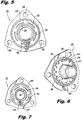
FIG. 6 is a perspective view of the seal assembly ofFig. 5 , showing the seal assembly together with another exemplary embodiment of a sleeve fitting. -
FIG. 7 is a perspective view of the seal assembly and sleeve fitting ofFIG. 6 viewed from a side generally opposite that shown inFig. 6 , showing the passages defined through the seal assembly and sleeve fitting. -
FIG. 8 is a cross-sectional elevation view of a portion of an exemplary embodiment, not covered by the claims, of a double wall tube assembly, showing and end of the assembly mounted to a double seal coupling. -
FIGS. 9-12 show exemplary stages of assembly in accordance with an embodiment of a method of assembling a double wall tube assembly in accordance with this disclosure. -
FIG. 13 is an exploded isometric view of a double wall tube and fitting assembly. -
FIG. 14 is an exploded isometric view of the fitting assembly ofFIG. 13 . -
FIG. 15 is a sectional view of one of the fittings of the fitting assembly ofFIG. 13 . -
FIG. 16 is a sectional view of the fitting assembly ofFIG. 13 . - Reference will now be made to the drawings wherein like reference numerals identify similar structural features or aspects of the subject disclosure. For purposes of explanation and illustration, and not limitation, a partial view of an exemplary embodiment of a double wall tube assembly in accordance with the disclosure is shown in
FIG. 1 and is designated generally byreference character 100. Other embodiments of double wall tube assemblies in accordance with the disclosure or aspects thereof, are provided inFIGS. 2-16 , as will be described. The systems and methods described herein can be used to provide redundancy, for example for conducting engine fluids through engines in aerospace applications. Another potential use is for co-axial flow, e.g., in a heat exchanger. - Double
wall tube assembly 100 includes aninner tube 102 extending in an axial direction between two opposed ends of theinner tube 102, i.e.,inner tube 102 extends along the curved axis A. The axial direction follows a bend radius r. Asleeve fitting 104a is mounted to one end ofinner tube 102. Anouter tube 106 outboard ofinner tube 102 extends in the axial direction between two opposed ends ofouter tube 106, i.e., the inner andouter tubes collar fitting 108a is mounted to one end ofouter tube 106 whereincollar fitting 108a is outboard ofsleeve fitting 104a. - A
second sleeve fitting 104b is mounted to an end of theinner tube 102 opposite the first sleeve fitting 104a. Asecond collar fitting 108b is mounted to an end ofouter tube 106 opposite thefirst collar fitting 108a.Inner tube 102 is longer in the axial direction thanouter tube 106. Thecollar fittings sleeve fittings - With reference now to
FIG. 2 , each of the first andsecond collar fittings axial end face 110 defining arespective seat 112. As shown inFIG. 1 , a respective one of the first andsecond sleeve fittings seat 112 of each respective collar fitting 108a and 108b to suspendinner tube 102 insideouter tube 106. - Referring now to
FIG. 3 , eachsleeve insert central bore 114 therethrough for fluid communication throughsleeve fittings inner tube 102. Eachsleeve insert FIG. 3 with reference characters for sake of clarity) outboard ofcentral bore 114 for fluid communication throughsleeve fittings passage 118 defined between the inner andouter tubes FIG. 1 , as described further below with reference toFIG. 7 . In the example shown inFIG. 3 , theperipheral passages 116 define axial bores through aradially extending flange 120 of each sleeve fitting 104a and 104b. It is also contemplated that the at least oneperipheral passage 216 can define a perimeter recess such as the spaces betweencastellations 217 in aradially extending flange 220 in the exemplary embodiment of asleeve fitting 204 shown inFIG. 6 . It is also contemplated that any other suitable type of perimeter recess can be used, such as by makingflange 220 have a polygonal periphery such as a pentagon, as indicated by the dashed lines inFIG. 3 . In this case, the edges between the points of the pentagon provide peripheral passages. - With reference now to
FIG. 4 , a junction of twotube assemblies 100 is described. InFIG. 4 , on the left is shown one end of atube assembly 100 as described above, with the end having sleeve fitting 104b and collar fitting 108b shown. On the right inFIG. 4 is shown asecond tube assembly 100 as described above, with the end having collar fitting 108a and sleeve fitting 104a shown. Aseal assembly 122 sealingly engages between thecollar fittings axial seals 124, which are axially compressed o-rings. Those skilled in the art will appreciate that any other type of seal can be used in addition to or in lieu of o-rings, such as a vulcanized seal.Seal assembly 122 also sealingly engages between the first andsecond sleeve fittings axial seals 126, which are axially compressed o-rings. This sealing arrangement allows for fluid isolation of flows through the junction of the two tube assemblies between theinner passage 119 of theinner tubes 102 and theouter passage 118. The two tube assemblies can be bolted together with a bolt passing throughbores 128 formed through thecollar fittings seal assembly 122. Only one of threebores 128 is shown inFIG. 4 , but seeFIGS. 2 and5 , where all three bores are shown in thecollar fittings seal assembly 122. While shown as circular, it is also contemplated that bores 128 can be elongated circumferentially around axis A, i.e., kidney bean shaped, for example to accommodate cumulative mismatches in configurations withmultiple tube assemblies 100 attached end to end. Simply removing the three flange bolts frees the double walled coupling allowing thetube assemblies 100 to be removed. - With reference now to
FIG. 5 ,seal assembly 122 includes fivepassages 130, although any other suitable number can be used, for passage of fluids betweenaxial seals FIG. 6 ,seal assembly 122 is shown aligned withsleeve fitting 204. As shown inFIG. 7 , the reverse side ofseal assembly 122 is shown from that inFIG. 6 , to show alignment ofperipheral passages 216 andpassages 130 to permit flow through the junction of twotube assemblies 100, wherein the main flow through the central passage is sealed off through the junction from flow throughpassages 130 for theouter passage 118 shown inFIG. 1 . This can be used, for example, to collect fluid inouter passage 118 leaked from the main flow for conveyance to a drain or the like, without junctions such as that shown inFIG. 4 adding to the leakage. - Referring to
FIG. 8 , it is contemplated that in lieu of collar and sleeve fittings, one end oftube assembly 100 can be mounted to a double sealedcoupling 132 or other suitable interface to connecttube assembly 100, or a plurality of connected tube assemblies, to an engine component. Double sealedcoupling 132 is exemplary, and can be any suitable fitting, e.g., a fitting that has co-axial weld ends that are offset axially to accommodate double wall tube. In the example shown inFIG. 8 ,tube assembly 100 is mounted to double sealedcoupling 132, which is welded to one end of each of the inner andouter tubes FIG. 8 , can be mounted to sleeve andcollar fittings tube assembly 100, e.g., as depicted inFIG. 4 , for example. Double sealedcoupling 132 provides an interface betweentube assembly 100 and afixture 134, which can provide fluid communication into an engine compartment, for example. - With reference now to
FIGS. 9-12 , an exemplary method of assembling tube assemblies such astube assemblies 100 is described. As shown inFIG. 9 , a first sleeve fitting 104a is mounted to an end of aninner tube 102, e.g., with a butt weld such as by orbital welding. Anouter tube 106 and a pair ofopposed collar fittings inner tube 102 as shown inFig. 10 . Prior to positioningouter tube 106 aboutinner tube 102, both can be bent to have a common bend radius. - As indicated in
FIG. 11 , a second sleeve fitting 104b is mounted, e.g., by butt welding, to an end of theinner tube 102 opposite the first sleeve fitting 104a. The mounting of thesleeve fittings outer tube 106 andcollar fittings inner tube 102 can include sliding thecollar fittings outer tube 106 and positioningouter tube 106 proximate first sleeve fitting 104a to clear an end area ofinner tube 102 for butt welding the second sleeve fitting 104b to theinner tube 102. To facilitate mounting sleeve fitting 104b toinner tube 102, the length ofouter tube 106 is shorter than the distance betweenflanges 120 of thesleeve fittings collar fittings sleeve fittings outer tubes Outer tube 106 is shorter thaninner tube 102, so by positioningouter tube 106 andcollar fittings inner tube 102. - As indicated in
FIG. 12 , the method also includes mounting a first one of the collar fittings, e.g., collar fitting 108a, to an end of theouter tube 106 and mounting a second one of the collar fittings, e.g., collar fitting 108b, to an end of theouter tube 106 opposite the first collar fitting. Thecollar fittings second sleeve fittings second collar fittings inner tube 102 with a passage, e.g.,passage 118 shown inFIG. 1 , defined betweeninner tube 102 andouter tube 106. - In the exemplary embodiment shown in
FIG. 8 , thefirst sleeve fitting 104a can be mounted to an end of aninner tube 102. Anouter tube 106 and a collar fitting 108a can be positioned about ofinner tube 102. A coupling interface can be mounted to an end of theinner tube 102 opposite the first sleeve fitting 104a, and an end of theouter tube 106 can be mounted to the coupling interface as well. The collar fitting 108a can be mounted to an end ofouter tube 108a opposite the coupling interface. -
FIG. 13 is an exploded isometric view of doublewall tube assembly 200, which includesinner tube 102,outer tube 106, andfastening assembly 201.Fastening assembly 201 includesseal assembly 122, andfitting assemblies - Fitting
assemblies seal assembly 122 has two sides which are identical.Inner tubes 102 connect to an inner sleeve connection (shown later) offitting assemblies Outer tubes 106 surroundinner tubes 102.Outer tubes 106 connect to an outer fitting (shown later) offitting assemblies - Fitting
assemblies Seal assembly 122 is fastened betweenassemblies assemblies assemblies seal assembly 122 create a union betweeninner tubes 102 and a union betweenouter tubes 106. The union fixes the position to inner andouter tubes fitting assemblies assembly 122. Inner andouter tubes fitting assemblies inner tubes 102 without travelling to the unpressurized section ofouter tubes 106. - In one embodiment of operation, pressurized fluid flows through
inner tube 102 and passes throughfitting assembly 208b. The pressurized fluid then flows throughseal assembly 122 before reachingfitting assembly 208a. Pressurized fluid may also flow in the opposite direction of the above described flow path. - Additionally, unpressurized fluid may flow through
outer tube 106 and pass throughfitting assembly 208b. The unpressurized fluid can then flow throughseal assembly 122 before reachingfitting assembly 208a. The unpressurized fluid may also flow in the opposite direction of the above described flow path. - Fitting
assemblies seal assembly 122,inner tubes 102, andouter tubes 106 are constructed out of metal. These components are all constructed out of the same metal for manufacturing ease and the avoidance of galvanic action between the metals. For example nickel or titanium alloys can be used. Steel alloys, including stainless steels such as AMS5557 SST can also be used. -
FIG. 14 is an exploded isometric view offastening assembly 201, which includesfitting assemblies seal assembly 122.Seal assembly 122 includesouter seal 124,inner seal 126, mounts 128, and slotpassages 130, andcenter port 214. Fittingassemblies surface 110, inner mountingsurface 111,center port 114,secondary groove 115,secondary passages 116, mounts 128,connection surface 138,inner connection 140, andouter connection 142. -
Seal assembly 122 andfitting assemblies -
Center port 214 ofseal assembly 122 is a circular bore through the center ofseal assembly 122.Inner seal 126 annularly circumscribescenter port 214.Inner seal 126 is spaced closely to centerport 214. Located radially outboard ofinner seal 126 areslot passages 130, which are spaced closely toinner seal 126.Slot passages 130 extend throughseal assembly 122 and together form an incomplete circle surroundinginner seal 126; however, the circle is not complete, leaving material ofseal assembly 122 circumferentially spacingslot passages 130. In this embodiment there are four ofslot passages 130; however, more or less may be used. Located radially outboard ofslot passages 130 isouter seal 124, which is also annular.Outer seal 124 is spaced closely to slotpassages 130.Outer seal 124 is located radially inboard ofmounts 128.Inner seal 126 andouter seal 124 are both flexible materials commonly used for sealing or gasketing. For example,inner seal 126 andouter seal 124 may be made of a vulcanized rubber or polymer. -
Mounts 128 ofseal assembly 122 are located near the perimeter ofseal assembly 122 and are equally spaced relative to one another and are equally spaced, radially, from the center ofseal assembly 122. In this embodiment, three mounts are shown; however more or fewer may be used.Mounts 128 includes bores which pass through mounts 128. The bores ofmounts 128 ofseal assembly 122 are circular. -
Center port 114 is a circular bore through the center offitting assemblies Surrounding center port 114 isinner connection 140.Inner connection 140 is a cylindrical protuberance, which extends orthogonally away fromconnection surface 138, or a sleeve fitting. Spaced radially outboard frominner connection 140 isouter connection 142, which is also a cylindrical protuberance extending orthogonally away fromconnection surface 138.Outer connection 142 completely surroundsinner connection 140. - Located radially between outer mounting
surface 110 and inner mountingsurface 111 issecondary groove 115.Secondary groove 115 completely separates inner and outer mating surfaces 111 and 110.Secondary groove 115 extends intoseal assemblies surface 110 and inner mountingsurface 111.Secondary groove 115 does not pass entirely throughseal assemblies secondary passages 116, which begin insecondary groove 115, do extend throughseal assemblies Secondary passages 116 are round bores that begin at the radially inner surface ofsecondary groove 115 and extend throughseal assemblies connection surface 138 betweeninner connection 140 andouter connection 142. Eight ofsecondary passages 116 are shown; however, more, or less may be used depending on the application. -
Mounts 128 offitting assemblies fitting assemblies fitting assemblies Mounts 128 includes bores which pass through mounts 128. The bores ofmounts 128 offitting assembly - Fitting
assemblies seal assembly 122 betweenfitting assemblies assembly 208a mounts to one side ofseal assembly 122 andfitting assembly 208b mounts to the other side ofseal assembly 122. When connected, outer mountingsurface 110 makes contact with the surface ofseal assembly 122. Also,outer surface 110 contacts, and compresses,outer seal 124. Inner mountingsurface 111 also makes contact with the surface ofseal assembly 122. Similarly, inner mountingsurface 111 contacts, and compresses,inner seal 126.Secondary groove 115 aligns withslot passages 130. The opening ofgroove 115 is aligned entirely between inner andouter seals Fitting assembly 208b connects to sealassembly 122 in the same manner, but on the opposite side ofseal assembly 122. - When fitting
assemblies seal assembly 122 between them, fasteners pass throughmounts 128 offitting assembly 208a, mounts 128 ofseal assembly 122, and throughmounts 128 offitting assembly 208b. The fasteners can then be tightened, drawingfitting assemblies outer seals seal assembly 122. - Fitting
assemblies outer seals 124 and 126) are each single pieces which are each formed from a single block of material. For example,fitting assembly 208a is machined from a single billet of stainless steel. Other methods of manufacturing can be used to formfitting assemblies -
FIG. 15 is an isometric sectional view of section 15-15 offitting assembly 208a ofFIG. 13 . However,FIG. 15 also includes inner andouter tubes FIG. 13 . Fittingassembly 208a includes outer mountingsurface 110, inner mountingsurface 111,center port 114,secondary groove 115,secondary passages 116, mounts 128,inner connection 140, andouter connection 142. - The components of
fitting assembly 208a are connected consistently withFIGS. 13 and14 ; however,FIG. 15 further illustrates the connection ofinner tube 102 andouter tube 106 tofitting assembly 208a. -
Inner tube 102 inserts intoinner connection 140 offitting assembly 208a.Inner connection 140 is designed so that its inner diameter (the diameter of fitting center bore 114) is large enough to allow tube inner 102 to be inserted, while leaving very little clearance between the outside ofinner tube 102 and inside ofinner connection 140.Inner tube 102 is inserted intoinner connection 140 until it nearly reaches inner mountingsurface 111. For example,inner tube 102 may be 0.05 to 0.20 inches (1.27 to 2.08 mm) away from the inner diameter of inner mountingsurface 111. However,inner tube 102 may also be inserted past mountingsurface 111 as well.Inner tube 102 is brazed toinner connection 140.Outer tube 106 is butted toouter connection 142, which is tapered for receivingouter tube 106.Outer tube 106 is butt welded toouter connection 142.Outer connection 142 may have a receiving collar in other embodiments. - In
manufacturing tube assembly 200,inner tube 102 has braze material (or brazing paste) applied to the outside of the end ofinner tube 102 that is to be inserted intoinner sleeve connection 140.Inner tube 102 is then inserted intoinner sleeve connection 140. Next,outer tube 106 is slid overinner tube 102 and is butted up toouter connection 142. Then,outer tube 106 is butt welded toouter connection 142. Other types of welds may be used in other embodiments oftube assembly 200. After weldingouter tube 106 toouter connection 142, the assembly is placed in a brazing furnace or oven to brazeinner tube 102 toinner sleeve connection 140. Thereafter, further steps, such as weld treatment, weld cleanup, and other finishing steps are performed. - One manufacturing benefit of having a brazed inner tube connection to the fitting is that it addresses shrinkage concerns. Because there are shrinkage concerns when welding or brazing parts together, brazing
inner tube 102 toinner connection 140 allowsinner tube 102 to be made longer than necessary for placement of the tube ininner connection 140 whereinner tube 102 protrudes through the end of fitting assembly 208. Then wheninner tube 102 settles out (meaning the length is finalized following thermal expansion and contraction from welding and brazing processes), and all shrinkage is accounted for, gaps or excessive pre-loads betweeninner tubes 102 are reduced. Any additionalinner tube 102 can simply be trimmed off to a desired length. -
FIG. 16 is a sectional view oftube assembly 200 at section 16-16 ofFIG. 13 .Tube assembly 200 includesinner tubes 102,outer tubes 106 andfastening assembly 201.Fastening assembly 201 includesfitting assemblies seal assembly 122.Seal assembly 122 includesouter seal 124,outer seal groove 125,inner seal 126,inner seal groove 127, mounts 128,slot passages 130, andcenter port 214. Fittingassemblies surface 110, inner mountingsurface 111,center port 114,secondary groove 115,secondary passages 116, mounts 128,connection surface 138,inner connection 140, andouter connection 142.FIG. 16 also shows fluid flow P and unpressurized fluid flow U. - The connection of the components of
tube assembly 200 is consistent withFIGS. 13-15 ; however,FIG. 16 provides further detail oftube assembly 200, specifically offastening assembly 201.Seal assembly 122 includesinner seal groove 127, which is a groove milled or otherwise machined into both faces ofseal assembly 122.Inner seal groove 127 is annular and located radially outboard ofseal center port 214.Outer seal groove 125 is similar to inner seal groove, but is located radially outboard ofinner seal groove 127.Inner seal groove 127 receives and retainsinner seal 126.Inner seal groove 127 is radially larger thaninner seal 126. Similarly,outer seal groove 125 receives and restrainsouter seal 124 and is radially larger thaninner seal 126. - As previously described,
fitting assemblies inner tubes 102 throughinner connections 140. For exampleinner tube 102 connects toinner connection 140 offitting assembly 208b (right hand connection).Inner tube 102 is inserted intoinner connection 140 from the connection surface side offitting assembly 208b and extends most of the way throughinner connection 140, but stops before reaching the inner diameter of inner mountingsurface 111. As previously discussed, this connection is secured by a furnace or oven braze process. - When fitting
assemblies assembly 122,seal center port 214 andcenter port 114 offitting assemblies seal center port 214 has a diameter slightly larger than the diameter offitting center ports 114 ofassemblies 208a and 208. Becausetubes 102 have an inner diameter smaller thancenter port 114 offitting assemblies 208a and 208, which have a smaller diameter thanseal port 214, the transition betweentubes 102 is not linear or smooth, but is tiered. - As previously described,
outer tubes 106 are butt welded toouter connections 142 of fitting assembliesfitting assemblies tubes 106 andouter connections 142 have the same inner diameter, the transition between these components is smooth. - When fasteners are passed through
mounts 128 offitting assemblies seal assembly 122 and tightened to pullfitting assemblies assembly 122, inner seals andouter seals surfaces inner seals inner seals outer seal grooves outer seals seal assembly 122 andfitting assemblies - With
fitting assemblies assembly 122, two flow paths are formed throughfastening assembly 201. The first flow path connectsinner tubes 102 throughinner connections 140 andseal center port 214. The first flow path is sealed by the brazed connections betweeninner tubes 102 andinner connections 140, and is sealed byinner gaskets 126. - The second flow path connects
outer tubes 106. For example,tube 106 is connected toouter connection 142 offitting assembly 208a, which connect tosecondary passages 116.Secondary passages 116 pass throughfitting assembly 208a from betweeninner connection 140 andouter connection 142, tosecondary groove 115 between inner and outer seal surfaces 111 and 110.Secondary groove 115 is aligned withslot passages 130 ofseal surface 122, which aligns withsecondary groove 115 offitting assembly 208b.Secondary groove 115 offitting assembly 208b connects tosecondary passages 116, which terminate between inner andouter connections fitting assembly 208b.Outer connection 142 connects toouter tube 106. Essentially, flow can pass fromouter tube 106 to the space between inner andouter connections fitting assembly 208a. Flow can then continue tosecondary passages 116 before continuing tosecondary groove 115 offitting assembly 208a and pass tosecondary groove 115 offitting assembly 208b throughslot passages 130 ofseal plate 122. Flow then continues tosecondary passages 116 offitting assembly 208b and exits between inner andouter connections outer tube 106. The second path is sealed by inner andouter seals outer connections 142 andouter tubes 106. - In the operation of one embodiment,
inner tubes 102 pass fluid flow P to each other through the first flow path described above. Typically, this flow is a pressurized liquid, such as gas, oil, or water. In normal operation, fluid flow P travels throughinner tube 102, briefly intofitting assembly 208b,seal assembly 122, andfitting assembly 208a, before continuing toinner tube 102. While infastening assembly 201, fluid flow P will encounter multiple changes in diameter. The diameter ofseal center port 214 is larger thancenter ports 114 andinner tubes 102 to minimize pressure drop throughfitting assembly 201 due to flow restrictions. This also reduces manufacturing interference wheninner tube 102 extends throughfitting assemblies - In normal operation of one embodiment, no flow will travel through the second flow path. However, in the case of a failure of one of
inner tubes 102, or a connection betweeninner tubes 102 and another component, some of fluid flow P may escape intoouter tube 106 becoming unpressurized fluid flowU. Outer tubes 106, which operates at ambient pressure, pass unpressurized fluid flow U throughfastening assembly 201 and onto a collection or inspection apparatus. This embodiment offers the benefit of preventing and collecting the leaking of fluid flow P. - Also, this embodiment benefits from the use of a single piece fitting assembly. Fitting
assemblies -
Secondary groove 115, which partially creates the second flow path above, provides several functions and benefits. First,secondary groove 115 helps to create the second flow path described above by enablingsecondary passages 116 offitting assembly 208a to connect tosecondary passages 116 offitting assembly 208b. Becauseinner seal 126 needs to seal fluid flow P,inner seal 126 needs to be create a fluid tight seal in close proximity to sealcenter port 214 andfitting center ports 114. To accomplish this,inner seal 126contacts mounting surface 111 adjacent to sealcenter port 214 andfitting center ports 114. Because of the location of the seal,outer tubes 106 cannot be linearly connected throughfastening assembly 201. As a solution,secondary flow passages 116 are drilled at angles throughfitting assemblies passages 130 are located radially outboard ofouter connection 142, where thesecondary flow passages 116 offitting assemblies inner seal 126. - Also,
secondary groove 115 improves the manufacturability offitting assemblies secondary flow paths 116 need to be drilled at angles throughfitting assemblies secondary groove 115 improves the accuracy, consistency, and ease of completing this process. -
Secondary groove 115 also offers the benefit of correcting misalignment in installation and manufacturing errors. Secondary flow passages are drilled in minimal locations. While allowing flow throughfastening assembly 201 is desired, drilling several holes equally spaced circumferentially throughfitting assemblies fitting assemblies 208 and 208b and adds manufacturing cost to these parts. Therefore, a balance is struck between allowing flow, increasing the manufacturing cost, and decreasing rigidity offitting assemblies secondary flow paths 116 may not always align betweenfitting assemblies flow paths 116 were manufactured improperly, or becausefitting assemblies 208 and 208b were improperly installed. Regardless, whensecondary flow paths 116 are not in perfect alignment,secondary groove 115 will pass fluid circumferentially.Slot passages 130 also play a role in this process. For example, when unpressurized fluid U flows intosecondary passage 116 offitting assembly 208asecondary groove 115 may distribute unpressurized fluid U circumferentially throughsecondary groove 115.Secondary groove 115 may then pass the unpressurized fluid flow U to slot passages, which pass unpressurized fluid flow U tosecondary groove 115 andsecondary passages 116 offitting assembly 208b. This process overcomes errors in manufacturing and assembly, and also acts to balance the flow throughsecondary passages 116. - In other embodiments, a pump may be used to collect unpressurized fluid flow U for reuse within a system. In another embodiment, unpressurized flow may be pressurized flow of a fluid that is the same or different than fluid flow P. These fluids may be placed in a double wall tube system to save space. In another embodiment, fluid flow P and unpressurized fluid flow U may be fluids that are of different temperatures placed adjacently to exchange heat between the fluids.
- Though the disclosure describes a double wall tube system carrying a pressurized flammable fluid, the methods of this disclosure can be applied to any double wall tube system having multiple pieces or requiring fittings.
- While the invention has been described with reference to an exemplary embodiment(s), it will be understood by those skilled in the art that various changes may be made and equivalents may be substituted for elements thereof without departing from the scope of the invention. In addition, many modifications may be made to adapt a particular situation or material to the teachings of the invention without departing from the scope thereof. Therefore, it is intended that the invention not be limited to the particular embodiment(s) disclosed, but that the invention will include all embodiments falling within the scope of the appended claims.
Claims (13)
- A flange fitting assembly comprising first and second flange fittings for attaching to first and second double wall tubes (110), respectively, and to each other, each flange fitting comprising:a fitting center port (114) extending through the fitting for passing a primary fluid flow;a plurality of flange fitting mounts (128) spaced radially away from the center port for receiving fasteners;an inner (111) and outer (110) seal surface that are predominantly flat;a connection surface (138) on a side of the fitting opposing the seal surfaces, the connection surface (138) comprising:an inner sleeve connection (140) protruding from the connection surface (138) surrounding the center port (114) for receiving an inner tube (102); andan outer connection (142) protruding from the connection surface (138) surrounding the inner sleeve connection (140) for receiving an outer tube (106); anda plurality of fluid communication ports for passing a secondary fluid flow, wherein the fluid communication ports extend through the flange fitting from between the inner (110) and outer (120) seal surfaces to the connection surface between the inner sleeve connection (140) and the outer connection (142), and wherein each flange fitting comprises a groove (115) extending axially from between the inner and outer seal surfaces (111, 110) into the fitting, and wherein the fluid communication ports extend through the fitting from a surface of the groove (115) through the connection surface (138) between the inner sleeve connection (140) and the outer connection (142), the flange fitting assembly (208) further comprising:a seal plate (122) for mounting between the first flange fitting and second flange fitting, the seal plate (122) comprising:
a plate center port (214) having an axis that is in alignment with a center axis of the fitting center port (114); a plurality of plate mounts (128) for receiving fasteners, wherein the plate mounts (128) are spaced radially away from the plate center port (214); a first side and a second side, wherein the first and second sides are identical, each side of the seal plate (122) comprising:an inner seal (126) circumscribing the plate center port (214); andan outer seal (124) located radially between the plate mounts (128) and the inner seal (126); anda plurality of slots (130) extending through the seal plate (122), located between the inner (126) and outer (124) seal of each side for passing a secondary fluid flow between the fluid communication ports of the first and second fittings. - The flange fitting assembly of claim 1, wherein there are eight fluid communication ports.
- The flange fitting assembly of claim 1 or 2, wherein the fitting is formed of a single piece.
- The flange fitting assembly of any preceding claim, wherein the fitting mounts (128) are slots.
- The flange fitting assembly of any preceding claim, wherein the fitting material is one of a titanium alloy, stainless steel alloy, or nickel alloy.
- The flange fitting assembly of claim 1, wherein the slots (130) of the seal plate (122) are configured to allow fluid to pass between the fluid communication ports of the first and second flange fittings without aligning the fluid communication ports of the first and second flange fitting.
- The flange fitting assembly of claim 1 or 6, wherein a diameter of the plate center port (214) is larger than a diameter of the fitting center ports (114) of the first and second flange fittings.
- The flange fitting assembly of any of claims 1, 6 or 7, wherein each side of the seal plate (122) has an annular groove (127) for securing the inner seal (126), and wherein each side of the seal plate (122) has an annular groove (125) for securing the outer seal (124), and optionally wherein the inner (126) and outer seal (124) expand to fill their grooves when the fittings are mated to the seal plate (122) and apply pressure compressing the inner (126) and outer (124) seals.
- The flange fitting assembly of any of claims 1, 6 or 7, wherein the inner (126) and outer (124) seals are vulcanized.
- The flange fitting assembly of any of claims 1, 7, 8 or 9, wherein the seal plate (122) has four slots.
- The flange fitting assembly of any of claims 1, 7, 8, 9 or 10, wherein the outer tube carries a fluid at an ambient pressure and the inner tube carries another fluid at an operational pressure.
- A method of manufacturing a double wall tube and flange fitting assembly (208), the method comprising:applying braze material to a first end of an inner tube (102);inserting the inner tube (102) into an inner sleeve connection of a first flange fitting;sliding an outer tube (106) over the inner tube (102) and butting the outer tube (106) against an outer connection (142) of the first flange fitting;welding the outer tube (106) to the outer connection (142); andbrazing the first end of the inner tube (102) to the inner sleeve connection (140),and further comprising fastening a second flange fitting and a seal plate (122) to the first flange fitting, and forming each of said flange fittings by:providing a fitting center port (114) extending through the fitting for passing a primary fluid flow;spacing a plurality of flange fitting mounts (128) radially away from the center port for receiving fasteners;forming said fittings to have an inner (111) and outer (110) seal surface that are predominantly flat;forming a connection surface (138) on a side of the fitting opposing the seal surfaces, the connection surface (138) comprising:an inner sleeve connection (140) protruding from the connection surface (138) surrounding the center port (114) for receiving said inner tube (102); andsaid outer connection (142) protruding from the connection surface (138) surrounding the inner sleeve connection (140) for receiving said outer tube (106); andforming a plurality of fluid communication ports for passing a secondary fluid flow, and forming the fluid communication ports to extend through the flange fitting from between the inner (110) and outer (120) seal surfaces to the connection surface between the inner sleeve connection (140) and the outer connection (142), and further providing a groove (115) extending axially from between the inner and outer seal surfaces (111, 110) into the fitting, and providing the fluid communication ports so as to extend through the fitting from a surface of the groove (125, 127) through the connection surface (138) between the inner sleeve connection (140) and the outer connection (142), the method further comprising:forming a plate center port (214) in the seal plate (122) to have an axis that is in alignment with a center axis of the fitting center port (114); providing a plurality of plate mounts (128) in the seal plate (122) for receiving fasteners, and spacing the plate mounts (128) away from the plate center port (214);forming a first side and a second side on the seal plate (122), wherein the first and second sides are identical, each side of the seal plate (122) comprising:an inner seal (126) circumscribing the plate center port (214); andan outer seal (124) located radially between the plate mounts (128) and the inner seal (126); and forminga plurality of slots (130) extending through the seal plate (122), located between the inner (126) and outer (124) seal of each side for passing a secondary fluid flow between the fluid communication ports of the first and second fittings.
- The method of claim 12, further comprising
machining the first flange fitting from a single billet and machining the second flange fitting from another single billet.
Applications Claiming Priority (3)
| Application Number | Priority Date | Filing Date | Title |
|---|---|---|---|
| US201462013755P | 2014-06-18 | 2014-06-18 | |
| US201462095298P | 2014-12-22 | 2014-12-22 | |
| US14/619,704 US10393302B2 (en) | 2014-06-18 | 2015-02-11 | Double wall tube bolted flange fitting |
Publications (2)
| Publication Number | Publication Date |
|---|---|
| EP2957805A1 EP2957805A1 (en) | 2015-12-23 |
| EP2957805B1 true EP2957805B1 (en) | 2018-08-01 |
Family
ID=53396388
Family Applications (1)
| Application Number | Title | Priority Date | Filing Date |
|---|---|---|---|
| EP15171988.7A Active EP2957805B1 (en) | 2014-06-18 | 2015-06-12 | Bolted flange fitting assembly for double wall tube |
Country Status (2)
| Country | Link |
|---|---|
| US (1) | US10393302B2 (en) |
| EP (1) | EP2957805B1 (en) |
Families Citing this family (10)
| Publication number | Priority date | Publication date | Assignee | Title |
|---|---|---|---|---|
| US10753916B2 (en) | 2017-01-17 | 2020-08-25 | Waters Technologies Corporation | Systems, methods, and devices for detecting leaks in a chromatography system |
| US11162622B2 (en) * | 2018-04-27 | 2021-11-02 | Raytheon Technologies Corporation | Wedge adapter seal |
| US10928076B2 (en) * | 2018-07-30 | 2021-02-23 | Trane International Inc. | Furnace inlet water collector |
| US10689921B1 (en) * | 2019-02-05 | 2020-06-23 | Fmc Technologies, Inc. | One-piece production/annulus bore stab with integral flow paths |
| US11660711B2 (en) * | 2019-06-06 | 2023-05-30 | Raytheon Technologies Corporation | Radially outward orbital welding technique as a joining method used for inner tube to fitting connections in double wall tube configurations |
| KR20220031108A (en) * | 2019-07-11 | 2022-03-11 | 램 리써치 코포레이션 | Sealing interface for adjusting radial and angular offsets |
| EP3862611A1 (en) * | 2020-02-07 | 2021-08-11 | Winterthur Gas & Diesel AG | Flange connection for connecting two double-walled pipe parts, gas supply system and large motor |
| US20230375120A1 (en) * | 2022-05-18 | 2023-11-23 | Trinity Bay Equipment Holdings, LLC | Pipe-in-pipe outer pipeline sealing systems and methods |
| US11761267B2 (en) * | 2022-06-21 | 2023-09-19 | Joe Fox | Telemetry marine riser |
| GB2620990A (en) * | 2022-07-29 | 2024-01-31 | Weir Pump And Valve Solutions Inc | Jacketed pipes and pump casings |
Family Cites Families (52)
| Publication number | Priority date | Publication date | Assignee | Title |
|---|---|---|---|---|
| US1217543A (en) * | 1914-01-14 | 1917-02-27 | William M White | Pipe-joint for double pipes. |
| US2695182A (en) | 1950-09-22 | 1954-11-23 | Horace T Potts Company | Jacketed pipe assembly |
| US3233927A (en) | 1963-03-28 | 1966-02-08 | Lee T Dewhirst | Conduit means |
| US3317221A (en) | 1963-08-29 | 1967-05-02 | Birwelco Ltd | Pipe joints |
| GB1283919A (en) | 1968-10-30 | 1972-08-02 | Mirrlees Blackstone Ltd | Coaxial pipes with couplings |
| DE2248039C3 (en) * | 1972-09-29 | 1975-10-30 | Motoren- Und Turbinen-Union Friedrichshafen Gmbh, 7990 Friedrichshafen | Sealing arrangement |
| US3871486A (en) | 1973-08-29 | 1975-03-18 | Bakerdrill Inc | Continuous coring system and apparatus |
| FR2342454A1 (en) | 1976-02-25 | 1977-09-23 | Schulz Wilhelm | FLANGE FOR HEATED OR COOLED PIPES BY FLUID LINER |
| US4067596A (en) | 1976-08-25 | 1978-01-10 | Smith International, Inc. | Dual flow passage drill stem |
| US4130304A (en) * | 1977-08-12 | 1978-12-19 | Don R. Hinderliter, Inc. | Well head seal assembly |
| US4723441A (en) | 1985-11-07 | 1988-02-09 | Ply-Flow Engineering, Inc. | Piping system for hazardous fluids |
| JPS63243585A (en) | 1986-11-18 | 1988-10-11 | 株式会社 リガルジヨイント | Joint for multiple pipe |
| EP0268251B1 (en) | 1986-11-18 | 1990-12-27 | Smc Corporation | Tube joint for use with multi-walled tube assembly |
| US5199747A (en) | 1991-05-16 | 1993-04-06 | Jahr Willi E | Connector assembly for double walled tubing |
| US5494318A (en) | 1993-04-29 | 1996-02-27 | Butts; Nicholas E. | Secondary containment system |
| US5611373A (en) | 1995-04-27 | 1997-03-18 | Handy & Harman Automotive Group, Inc. | Laminated fuel line and connector |
| US6402159B1 (en) * | 1997-04-08 | 2002-06-11 | Gary A. Kohn | Dielectric gasket |
| US5931184A (en) | 1997-06-10 | 1999-08-03 | Armenia; John G. | Safety hose for delivering water to an appliance |
| NO310585B1 (en) | 1998-03-25 | 2001-07-23 | Reslink As | Pipe connection for connection of double walled pipes |
| IT244388Y1 (en) | 1998-11-23 | 2002-03-11 | Nupi S P A | FITTINGS FOR DOUBLE WALL PIPES |
| FR2804197B1 (en) | 2000-01-24 | 2002-07-12 | Coflexip | LIMITING DEVICE FOR THE PROPAGATION OF A DEFORMATION IN A DOUBLE WALL PIPE FOR LARGE DEPTHS |
| US6231086B1 (en) | 2000-03-24 | 2001-05-15 | Unisert Multiwall Systems, Inc. | Pipe-in-pipe mechanical bonded joint assembly |
| DE10044336A1 (en) | 2000-09-07 | 2002-03-21 | Uhde Hochdrucktechnik Gmbh | Flange connection for high pressure double jacket pipes |
| DE10064227C1 (en) | 2000-12-22 | 2002-06-20 | Airbus Gmbh | Connecting device for two double-wall tube lines has fixing body fixed to inner tube outer wall of first inner tube line close to inner tube line's coupled end |
| DE10143290B4 (en) | 2001-09-04 | 2006-02-09 | Esser-Werke Kg | Arcuate double layer pipe |
| US6886388B1 (en) | 2002-04-24 | 2005-05-03 | Mcgill M. Daniel | Contiguous double containment underground storage tank fueling system and methods for detecting leaks therein |
| US6848720B2 (en) | 2002-08-09 | 2005-02-01 | The Boeing Company | Shrouded fluid-conducting apparatus |
| US6854487B2 (en) | 2003-06-26 | 2005-02-15 | General Electric Company | Fluid conduit wall inhibiting heat transfer and method for making |
| KR100590619B1 (en) | 2004-08-05 | 2006-06-19 | 이보영 | Heat Plate for welding the pipe with multi-walls and the method for welding the same |
| US7322378B2 (en) | 2004-10-28 | 2008-01-29 | Winbond Electronics Corp. | Semiconductor apparatuses and pipe supports thereof |
| EP1731823A1 (en) * | 2005-06-08 | 2006-12-13 | Single Buoy Moorings Inc. | Cryogenic transfer hose |
| GB0523573D0 (en) | 2005-11-18 | 2005-12-28 | Airbus Uk Ltd | Aircraft fuel pipe coupling |
| JP4698417B2 (en) | 2005-12-28 | 2011-06-08 | 株式会社デンソー | Manufacturing method of double pipe |
| EP1953517B1 (en) | 2007-02-05 | 2016-07-13 | Nexans | Assembly for monitoring the permeability of an evacuated area |
| GB2453155A (en) | 2007-09-26 | 2009-04-01 | Rolls Royce Plc | Co-axial pipe assembly which supplies oil to a bearing in a gas turbine engine |
| DE102007051436B4 (en) | 2007-10-25 | 2010-01-28 | H. Butting Gmbh & Co. Kg | Connection system for double-walled pipes |
| US7942452B2 (en) | 2007-11-20 | 2011-05-17 | The Boeing Company | Flange fitting with leak sensor port |
| ES2331225B1 (en) | 2008-04-25 | 2010-09-29 | Eads Construcciones Aeronauticas, S.A. | DOUBLE WALL CONDUCT SYSTEM. |
| EP2307530A1 (en) | 2008-07-10 | 2011-04-13 | Shell Internationale Research Maatschappij B.V. | Process for removing a gaseous contaminant from a contaminated gas stream |
| US20100275572A1 (en) | 2009-04-30 | 2010-11-04 | Pratt & Whitney Canada Corp. | Oil line insulation system for mid turbine frame |
| DE102009052674B4 (en) | 2009-11-12 | 2012-10-18 | Karl Weinhold | Method and device for connecting double-walled pipes |
| US8308200B1 (en) * | 2010-04-21 | 2012-11-13 | River Bend Transfer Systems, LLC | Quick connect hose-in-hose coupler |
| DE102011010385A1 (en) | 2011-02-05 | 2012-08-09 | Eads Deutschland Gmbh | Double-walled pipe and manufacturing process |
| FR2977299B1 (en) | 2011-07-01 | 2014-11-07 | Airbus Operations Sas | DOUBLE SKIN TUBING SYSTEM, JOINT SYSTEM BETWEEN TWO TUBE PORTIONS, AND AIRCRAFT PROVIDED WITH SUCH A SYSTEM |
| FR2981141A1 (en) | 2011-10-07 | 2013-04-12 | Dassault Aviat | CONDUIT OF TRANSPORT OF A DOUBLE-WALL FLUID, INSTALLATION OF SUCH A DRIVING AND AIRCRAFT COMPRISING SUCH A CONDUCT |
| WO2013086191A1 (en) | 2011-12-07 | 2013-06-13 | Polyflow Llc | Pipe system with annulus utilization and monitoring |
| US8770628B2 (en) | 2012-01-12 | 2014-07-08 | Reelwell, A.S. | Seal assembly for nested dual drill pipe |
| US8944749B2 (en) | 2012-01-24 | 2015-02-03 | Pratt & Whitney Canada Corp. | Oil purge system for a mid turbine frame |
| US8820794B1 (en) * | 2012-07-05 | 2014-09-02 | James C. Betz | Hose-in-hose coupler |
| US9903224B2 (en) | 2012-12-29 | 2018-02-27 | United Technologies Corporation | Scupper channelling in gas turbine modules |
| US9234614B2 (en) * | 2014-05-05 | 2016-01-12 | Electro-Motive Diesel, Inc. | Assembly for coupling a pair of double-walled tubes |
| US9829124B2 (en) | 2014-06-18 | 2017-11-28 | United Technologies Corporation | Double wall tube assemblies |
-
2015
- 2015-02-11 US US14/619,704 patent/US10393302B2/en active Active
- 2015-06-12 EP EP15171988.7A patent/EP2957805B1/en active Active
Also Published As
| Publication number | Publication date |
|---|---|
| US20150369413A1 (en) | 2015-12-24 |
| EP2957805A1 (en) | 2015-12-23 |
| US10393302B2 (en) | 2019-08-27 |
Similar Documents
| Publication | Publication Date | Title |
|---|---|---|
| EP2957805B1 (en) | Bolted flange fitting assembly for double wall tube | |
| EP2957804B1 (en) | Double wall tube assemblies | |
| CA2520160C (en) | Jacketed pipe flange and method | |
| KR101805117B1 (en) | Construction method for high pressure natural gas pipe line utilizing flanged pipes | |
| US8424925B2 (en) | Split fitting for pipe | |
| US20220090709A1 (en) | Dual-walled fluid transportation systems and related methods | |
| EP3246609B1 (en) | Shrouded pipe | |
| US6199254B1 (en) | Swaging tool with multiple pushers | |
| US10746330B2 (en) | Pipe coupling | |
| WO2022008696A1 (en) | Gasket assembly | |
| EP3246610B1 (en) | Shrouded pipe | |
| US4662660A (en) | Weldless high-pressure pipe fitting | |
| US20170307125A1 (en) | Orifice Fitting | |
| IE45192B1 (en) | Ethods for repairing underwater pipelines | |
| EP3073168B1 (en) | Double wall tube fitting with an integrated diagnostic port | |
| US20210333056A1 (en) | Heat exchanger header fabricated with integral flange using additive metal process | |
| SE518971C2 (en) | Feeding device for a plate heat exchanger, plate heat exchanger and method for manufacturing such a | |
| RU29357U1 (en) | Flange joint | |
| RU2746756C1 (en) | Mechanical connection of pipes of main pipelines | |
| US20220252187A1 (en) | A joint assembly and associated method | |
| GB2129897A (en) | Joining pipes | |
| RU2746030C1 (en) | Mechanical connection of medium pipes | |
| RU2742671C1 (en) | Mechanical connection of large diameter pipes | |
| RU2747547C1 (en) | Mechanical connection of small-diameter pipes | |
| JP2002327881A (en) | Coupling for fluid piping |
Legal Events
| Date | Code | Title | Description |
|---|---|---|---|
| PUAI | Public reference made under article 153(3) epc to a published international application that has entered the european phase |
Free format text: ORIGINAL CODE: 0009012 |
|
| AK | Designated contracting states |
Kind code of ref document: A1 Designated state(s): AL AT BE BG CH CY CZ DE DK EE ES FI FR GB GR HR HU IE IS IT LI LT LU LV MC MK MT NL NO PL PT RO RS SE SI SK SM TR |
|
| AX | Request for extension of the european patent |
Extension state: BA ME |
|
| 17P | Request for examination filed |
Effective date: 20160621 |
|
| RBV | Designated contracting states (corrected) |
Designated state(s): AL AT BE BG CH CY CZ DE DK EE ES FI FR GB GR HR HU IE IS IT LI LT LU LV MC MK MT NL NO PL PT RO RS SE SI SK SM TR |
|
| RAP1 | Party data changed (applicant data changed or rights of an application transferred) |
Owner name: UNITED TECHNOLOGIES CORPORATION |
|
| STAA | Information on the status of an ep patent application or granted ep patent |
Free format text: STATUS: EXAMINATION IS IN PROGRESS |
|
| 17Q | First examination report despatched |
Effective date: 20170519 |
|
| GRAP | Despatch of communication of intention to grant a patent |
Free format text: ORIGINAL CODE: EPIDOSNIGR1 |
|
| STAA | Information on the status of an ep patent application or granted ep patent |
Free format text: STATUS: GRANT OF PATENT IS INTENDED |
|
| INTG | Intention to grant announced |
Effective date: 20180125 |
|
| INTG | Intention to grant announced |
Effective date: 20180125 |
|
| GRAS | Grant fee paid |
Free format text: ORIGINAL CODE: EPIDOSNIGR3 |
|
| GRAA | (expected) grant |
Free format text: ORIGINAL CODE: 0009210 |
|
| STAA | Information on the status of an ep patent application or granted ep patent |
Free format text: STATUS: THE PATENT HAS BEEN GRANTED |
|
| AK | Designated contracting states |
Kind code of ref document: B1 Designated state(s): AL AT BE BG CH CY CZ DE DK EE ES FI FR GB GR HR HU IE IS IT LI LT LU LV MC MK MT NL NO PL PT RO RS SE SI SK SM TR |
|
| REG | Reference to a national code |
Ref country code: GB Ref legal event code: FG4D |
|
| REG | Reference to a national code |
Ref country code: CH Ref legal event code: EP Ref country code: AT Ref legal event code: REF Ref document number: 1024692 Country of ref document: AT Kind code of ref document: T Effective date: 20180815 |
|
| REG | Reference to a national code |
Ref country code: IE Ref legal event code: FG4D |
|
| REG | Reference to a national code |
Ref country code: DE Ref legal event code: R096 Ref document number: 602015014196 Country of ref document: DE |
|
| REG | Reference to a national code |
Ref country code: NL Ref legal event code: MP Effective date: 20180801 |
|
| REG | Reference to a national code |
Ref country code: LT Ref legal event code: MG4D |
|
| REG | Reference to a national code |
Ref country code: AT Ref legal event code: MK05 Ref document number: 1024692 Country of ref document: AT Kind code of ref document: T Effective date: 20180801 |
|
| PG25 | Lapsed in a contracting state [announced via postgrant information from national office to epo] |
Ref country code: SE Free format text: LAPSE BECAUSE OF FAILURE TO SUBMIT A TRANSLATION OF THE DESCRIPTION OR TO PAY THE FEE WITHIN THE PRESCRIBED TIME-LIMIT Effective date: 20180801 Ref country code: BG Free format text: LAPSE BECAUSE OF FAILURE TO SUBMIT A TRANSLATION OF THE DESCRIPTION OR TO PAY THE FEE WITHIN THE PRESCRIBED TIME-LIMIT Effective date: 20181101 Ref country code: GR Free format text: LAPSE BECAUSE OF FAILURE TO SUBMIT A TRANSLATION OF THE DESCRIPTION OR TO PAY THE FEE WITHIN THE PRESCRIBED TIME-LIMIT Effective date: 20181102 Ref country code: RS Free format text: LAPSE BECAUSE OF FAILURE TO SUBMIT A TRANSLATION OF THE DESCRIPTION OR TO PAY THE FEE WITHIN THE PRESCRIBED TIME-LIMIT Effective date: 20180801 Ref country code: NL Free format text: LAPSE BECAUSE OF FAILURE TO SUBMIT A TRANSLATION OF THE DESCRIPTION OR TO PAY THE FEE WITHIN THE PRESCRIBED TIME-LIMIT Effective date: 20180801 Ref country code: LT Free format text: LAPSE BECAUSE OF FAILURE TO SUBMIT A TRANSLATION OF THE DESCRIPTION OR TO PAY THE FEE WITHIN THE PRESCRIBED TIME-LIMIT Effective date: 20180801 Ref country code: PL Free format text: LAPSE BECAUSE OF FAILURE TO SUBMIT A TRANSLATION OF THE DESCRIPTION OR TO PAY THE FEE WITHIN THE PRESCRIBED TIME-LIMIT Effective date: 20180801 Ref country code: FI Free format text: LAPSE BECAUSE OF FAILURE TO SUBMIT A TRANSLATION OF THE DESCRIPTION OR TO PAY THE FEE WITHIN THE PRESCRIBED TIME-LIMIT Effective date: 20180801 Ref country code: NO Free format text: LAPSE BECAUSE OF FAILURE TO SUBMIT A TRANSLATION OF THE DESCRIPTION OR TO PAY THE FEE WITHIN THE PRESCRIBED TIME-LIMIT Effective date: 20181101 Ref country code: AT Free format text: LAPSE BECAUSE OF FAILURE TO SUBMIT A TRANSLATION OF THE DESCRIPTION OR TO PAY THE FEE WITHIN THE PRESCRIBED TIME-LIMIT Effective date: 20180801 Ref country code: IS Free format text: LAPSE BECAUSE OF FAILURE TO SUBMIT A TRANSLATION OF THE DESCRIPTION OR TO PAY THE FEE WITHIN THE PRESCRIBED TIME-LIMIT Effective date: 20181201 |
|
| PG25 | Lapsed in a contracting state [announced via postgrant information from national office to epo] |
Ref country code: LV Free format text: LAPSE BECAUSE OF FAILURE TO SUBMIT A TRANSLATION OF THE DESCRIPTION OR TO PAY THE FEE WITHIN THE PRESCRIBED TIME-LIMIT Effective date: 20180801 Ref country code: HR Free format text: LAPSE BECAUSE OF FAILURE TO SUBMIT A TRANSLATION OF THE DESCRIPTION OR TO PAY THE FEE WITHIN THE PRESCRIBED TIME-LIMIT Effective date: 20180801 Ref country code: AL Free format text: LAPSE BECAUSE OF FAILURE TO SUBMIT A TRANSLATION OF THE DESCRIPTION OR TO PAY THE FEE WITHIN THE PRESCRIBED TIME-LIMIT Effective date: 20180801 |
|
| PG25 | Lapsed in a contracting state [announced via postgrant information from national office to epo] |
Ref country code: RO Free format text: LAPSE BECAUSE OF FAILURE TO SUBMIT A TRANSLATION OF THE DESCRIPTION OR TO PAY THE FEE WITHIN THE PRESCRIBED TIME-LIMIT Effective date: 20180801 Ref country code: CZ Free format text: LAPSE BECAUSE OF FAILURE TO SUBMIT A TRANSLATION OF THE DESCRIPTION OR TO PAY THE FEE WITHIN THE PRESCRIBED TIME-LIMIT Effective date: 20180801 Ref country code: IT Free format text: LAPSE BECAUSE OF FAILURE TO SUBMIT A TRANSLATION OF THE DESCRIPTION OR TO PAY THE FEE WITHIN THE PRESCRIBED TIME-LIMIT Effective date: 20180801 Ref country code: EE Free format text: LAPSE BECAUSE OF FAILURE TO SUBMIT A TRANSLATION OF THE DESCRIPTION OR TO PAY THE FEE WITHIN THE PRESCRIBED TIME-LIMIT Effective date: 20180801 Ref country code: ES Free format text: LAPSE BECAUSE OF FAILURE TO SUBMIT A TRANSLATION OF THE DESCRIPTION OR TO PAY THE FEE WITHIN THE PRESCRIBED TIME-LIMIT Effective date: 20180801 |
|
| REG | Reference to a national code |
Ref country code: DE Ref legal event code: R097 Ref document number: 602015014196 Country of ref document: DE |
|
| PG25 | Lapsed in a contracting state [announced via postgrant information from national office to epo] |
Ref country code: SK Free format text: LAPSE BECAUSE OF FAILURE TO SUBMIT A TRANSLATION OF THE DESCRIPTION OR TO PAY THE FEE WITHIN THE PRESCRIBED TIME-LIMIT Effective date: 20180801 Ref country code: DK Free format text: LAPSE BECAUSE OF FAILURE TO SUBMIT A TRANSLATION OF THE DESCRIPTION OR TO PAY THE FEE WITHIN THE PRESCRIBED TIME-LIMIT Effective date: 20180801 Ref country code: SM Free format text: LAPSE BECAUSE OF FAILURE TO SUBMIT A TRANSLATION OF THE DESCRIPTION OR TO PAY THE FEE WITHIN THE PRESCRIBED TIME-LIMIT Effective date: 20180801 |
|
| PLBE | No opposition filed within time limit |
Free format text: ORIGINAL CODE: 0009261 |
|
| STAA | Information on the status of an ep patent application or granted ep patent |
Free format text: STATUS: NO OPPOSITION FILED WITHIN TIME LIMIT |
|
| 26N | No opposition filed |
Effective date: 20190503 |
|
| PG25 | Lapsed in a contracting state [announced via postgrant information from national office to epo] |
Ref country code: SI Free format text: LAPSE BECAUSE OF FAILURE TO SUBMIT A TRANSLATION OF THE DESCRIPTION OR TO PAY THE FEE WITHIN THE PRESCRIBED TIME-LIMIT Effective date: 20180801 |
|
| PG25 | Lapsed in a contracting state [announced via postgrant information from national office to epo] |
Ref country code: MC Free format text: LAPSE BECAUSE OF FAILURE TO SUBMIT A TRANSLATION OF THE DESCRIPTION OR TO PAY THE FEE WITHIN THE PRESCRIBED TIME-LIMIT Effective date: 20180801 |
|
| REG | Reference to a national code |
Ref country code: CH Ref legal event code: PL |
|
| REG | Reference to a national code |
Ref country code: BE Ref legal event code: MM Effective date: 20190630 |
|
| PG25 | Lapsed in a contracting state [announced via postgrant information from national office to epo] |
Ref country code: TR Free format text: LAPSE BECAUSE OF FAILURE TO SUBMIT A TRANSLATION OF THE DESCRIPTION OR TO PAY THE FEE WITHIN THE PRESCRIBED TIME-LIMIT Effective date: 20180801 |
|
| PG25 | Lapsed in a contracting state [announced via postgrant information from national office to epo] |
Ref country code: IE Free format text: LAPSE BECAUSE OF NON-PAYMENT OF DUE FEES Effective date: 20190612 |
|
| PG25 | Lapsed in a contracting state [announced via postgrant information from national office to epo] |
Ref country code: LI Free format text: LAPSE BECAUSE OF NON-PAYMENT OF DUE FEES Effective date: 20190630 Ref country code: LU Free format text: LAPSE BECAUSE OF NON-PAYMENT OF DUE FEES Effective date: 20190612 Ref country code: BE Free format text: LAPSE BECAUSE OF NON-PAYMENT OF DUE FEES Effective date: 20190630 Ref country code: CH Free format text: LAPSE BECAUSE OF NON-PAYMENT OF DUE FEES Effective date: 20190630 |
|
| PG25 | Lapsed in a contracting state [announced via postgrant information from national office to epo] |
Ref country code: PT Free format text: LAPSE BECAUSE OF FAILURE TO SUBMIT A TRANSLATION OF THE DESCRIPTION OR TO PAY THE FEE WITHIN THE PRESCRIBED TIME-LIMIT Effective date: 20181201 |
|
| PG25 | Lapsed in a contracting state [announced via postgrant information from national office to epo] |
Ref country code: CY Free format text: LAPSE BECAUSE OF FAILURE TO SUBMIT A TRANSLATION OF THE DESCRIPTION OR TO PAY THE FEE WITHIN THE PRESCRIBED TIME-LIMIT Effective date: 20180801 |
|
| PG25 | Lapsed in a contracting state [announced via postgrant information from national office to epo] |
Ref country code: HU Free format text: LAPSE BECAUSE OF FAILURE TO SUBMIT A TRANSLATION OF THE DESCRIPTION OR TO PAY THE FEE WITHIN THE PRESCRIBED TIME-LIMIT; INVALID AB INITIO Effective date: 20150612 Ref country code: MT Free format text: LAPSE BECAUSE OF FAILURE TO SUBMIT A TRANSLATION OF THE DESCRIPTION OR TO PAY THE FEE WITHIN THE PRESCRIBED TIME-LIMIT Effective date: 20180801 |
|
| PG25 | Lapsed in a contracting state [announced via postgrant information from national office to epo] |
Ref country code: MK Free format text: LAPSE BECAUSE OF FAILURE TO SUBMIT A TRANSLATION OF THE DESCRIPTION OR TO PAY THE FEE WITHIN THE PRESCRIBED TIME-LIMIT Effective date: 20180801 |
|
| REG | Reference to a national code |
Ref country code: DE Ref legal event code: R081 Ref document number: 602015014196 Country of ref document: DE Owner name: RAYTHEON TECHNOLOGIES CORPORATION (N.D.GES.D.S, US Free format text: FORMER OWNER: UNITED TECHNOLOGIES CORPORATION, FARMINGTON, CONN., US |
|
| P01 | Opt-out of the competence of the unified patent court (upc) registered |
Effective date: 20230520 |
|
| PGFP | Annual fee paid to national office [announced via postgrant information from national office to epo] |
Ref country code: FR Payment date: 20230523 Year of fee payment: 9 Ref country code: DE Payment date: 20230523 Year of fee payment: 9 |
|
| PGFP | Annual fee paid to national office [announced via postgrant information from national office to epo] |
Ref country code: GB Payment date: 20230523 Year of fee payment: 9 |