US7322378B2 - Semiconductor apparatuses and pipe supports thereof - Google Patents
Semiconductor apparatuses and pipe supports thereof Download PDFInfo
- Publication number
- US7322378B2 US7322378B2 US10/974,710 US97471004A US7322378B2 US 7322378 B2 US7322378 B2 US 7322378B2 US 97471004 A US97471004 A US 97471004A US 7322378 B2 US7322378 B2 US 7322378B2
- Authority
- US
- United States
- Prior art keywords
- pipe
- support ring
- end surface
- support
- inner bore
- Prior art date
- Legal status (The legal status is an assumption and is not a legal conclusion. Google has not performed a legal analysis and makes no representation as to the accuracy of the status listed.)
- Expired - Lifetime, expires
Links
Images


Classifications
-
- F—MECHANICAL ENGINEERING; LIGHTING; HEATING; WEAPONS; BLASTING
- F16—ENGINEERING ELEMENTS AND UNITS; GENERAL MEASURES FOR PRODUCING AND MAINTAINING EFFECTIVE FUNCTIONING OF MACHINES OR INSTALLATIONS; THERMAL INSULATION IN GENERAL
- F16L—PIPES; JOINTS OR FITTINGS FOR PIPES; SUPPORTS FOR PIPES, CABLES OR PROTECTIVE TUBING; MEANS FOR THERMAL INSULATION IN GENERAL
- F16L7/00—Supporting pipes or cables inside other pipes or sleeves, e.g. for enabling pipes or cables to be inserted or withdrawn from under roads or railways without interruption of traffic
- F16L7/02—Supporting pipes or cables inside other pipes or sleeves, e.g. for enabling pipes or cables to be inserted or withdrawn from under roads or railways without interruption of traffic and sealing the pipes or cables inside the other pipes, cables or sleeves
-
- F—MECHANICAL ENGINEERING; LIGHTING; HEATING; WEAPONS; BLASTING
- F16—ENGINEERING ELEMENTS AND UNITS; GENERAL MEASURES FOR PRODUCING AND MAINTAINING EFFECTIVE FUNCTIONING OF MACHINES OR INSTALLATIONS; THERMAL INSULATION IN GENERAL
- F16L—PIPES; JOINTS OR FITTINGS FOR PIPES; SUPPORTS FOR PIPES, CABLES OR PROTECTIVE TUBING; MEANS FOR THERMAL INSULATION IN GENERAL
- F16L9/00—Rigid pipes
- F16L9/18—Double-walled pipes; Multi-channel pipes or pipe assemblies
Definitions
- the invention relates to high-temperature pipe supports, and in particular to high-temperature pipe supports for semiconductor apparatuses.
- FIG. 1A is a partial cross section of a conventional chemical vapor deposition (CVD) apparatus.
- the conventional CVD apparatus 10 comprises a seat 12 , support ring 14 , outer pipe 16 , and inner pipe 18 .
- the support ring 14 is disposed on the inner bore of the seat 12 near the bottom thereof.
- the inner pipe 18 and the outer pipe 16 are separately disposed on the seat 12 and support ring 14 .
- the inner pipe 18 defines a sealed reaction chamber 182 .
- wafers are transferred into the reaction chamber 182 via a robot from the bottom entrance 184 .
- the entrance 184 is closed and sealed, forming a vacuum in the reaction chamber 182 prior to CVD processes.
- the conventional inner pipe 18 and outer pipe 16 is quartz.
- the seat 12 and support ring 14 are stainless steel.
- the seat 12 is water-cooled from the outer bore and the sidewall adjacent to the gas outlet 122 .
- silicide will coat the inner surfaces of the seat 12 and gas outlet 122 .
- the coated silicide peels easily, however, producing particles P in the buffer space between the inner and outer pipes 16 and 18 .
- FIG. 1B is an enlarged view of area a in FIG. 1A .
- the conventional support ring 14 comprises a lead angle 144 around the inner upper edge such that particles P easily accumulate in the recess between the inner pipe 18 and the support ring 14 . Particles P may be sucked into the reaction chamber 182 through the gap between the inner pipe 18 and the support ring 14 when the vacuum of the reaction chamber 182 is breaking and the entrance 184 is opened.
- the silicide particles can be a principle reaction chamber contaminant source in a conventional CVD apparatus.
- An exemplary embodiment of a pipe support comprises a seat and a support ring.
- the seat comprises a tubular portion for supporting an outer pipe at a top end thereof.
- the support ring with a flange and an end surface is detachably disposed within the tubular portion.
- the flange is disposed on an inner bore of the support ring, for supporting an inner pipe.
- the end surface is outwardly inclined from the inner bore to an outer bore of the support ring.
- An exemplary embodiment of a semiconductor apparatus comprises an outer pipe, an inner pipe, and a pipe support.
- the pipe support comprises a seat and a support ring.
- the seat further comprises a tubular portion for supporting an outer pipe at a top end thereof.
- the support ring with an end surface and an inner bore is detachably disposed within the tubular portion.
- the end surface is inclined to the inner bore by an acute angle.
- the flange comprises a top surface perpendicular to the inner bore of the support ring.
- the end surface is inclined to the inner bore by an angle between 25° and 85°.
- the intersection of the end surface and the inner bore is higher than the intersection of the end surface and the outer bore of the support ring.
- the end surface is an annular flat surface, annular concave surface, or annular convex surface.
- FIG. 1A is a partial cross section of a conventional CVD apparatus
- FIG. 1B is an enlarged view of area a in FIG. 1A ;
- FIG. 2 is a partial cross section of an embodiment of a CVD apparatus of the present invention
- FIG. 3A is a schematic top view of the support ring in FIG. 2 ;
- FIG. 3B is a schematic side view of the support ring in FIG. 2 ;
- FIGS. 4A-4C show partial cross sections of several embodiments of support rings of the present invention.
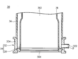
- FIG. 2 is a partial cross section of an embodiment of a CVD apparatus of the present invention.
- the CVD apparatus 30 comprises an inner pipe 38 , outer pipe 36 , and a pipe support 34 .
- the inner pipe 38 and outer pipe 36 are quartz.
- the pipe support 34 comprises a seat 32 and a support ring 20 .
- the seat 32 further comprises a tubular portion 324 and a gas outlet 322 connected thereto.
- the outer pipe 36 is disposed at a top end of the tubular portion 324 .
- the support ring 20 is detachably disposed within the tubular portion adjacent to the bottom thereof.
- the inner pipe 38 is disposed on the support ring 20 and defines a sealed reaction chamber 382 .
- wafers are transferred into the reaction chamber 382 via a robot from the bottom entrance 384 .
- the entrance 384 is closed and sealed, forming a vacuum in the reaction chamber 382 prior to CVD processes.
- FIGS. 3A and 3B are schematic top and side views of the support ring in FIG. 2 .
- the support ring 20 comprises a plurality of lugs 25 , a flange 21 , and an end surface 23 .
- the lugs 25 engage the assembly grooves of the seat 32 , securing the support ring 20 to the inner bore of the tubular portion 324 of the seat 32 .
- the flange 21 is located on the inner bore 22 of the support ring 20 , for supporting the inner pipe 38 .
- the end surface 23 is outwardly inclined from the inner bore 22 to the outer bore 24 of the support ring 20 .
- FIG. 4A shows a partial cross sections of an embodiment of a support ring.
- the flange 21 comprises a horizontal top surface 211 perpendicular to the inner bore 22 of the support ring 20 .
- the end surface 23 is an annular flat surface inclined to the inner bore 22 by an acute angle ⁇ between 25° and 85°.
- the intersection of the end surface 23 and the inner bore 22 is higher than the intersection of the end surface 23 and the outer bore 24 of the support ring 20 .
- Particles P tend to accumulate at the depressed outer bore 24 adjacent to the sidewall of the seat 32 .
- some embodiments of the pipe support 34 may potentially prevent accumulation of particles P between the inner pipe 38 and support ring 20 .
- the possibility that particles P will enter the reaction chamber 382 through the gap g therebetween may be reduced.
- the end surface of the support ring can also be an annular concave surface 23 ′ as shown in FIG. 4B , or an annular convex surface 23 ′′ as shown in FIG. 4C .
- the tangents of the end surfaces 23 ′ and 23 ′′ are individually inclined to the inner bore of the support ring 20 by an acute angle ⁇ .
- the intersections of the end surfaces 23 ′ and 23 ′′ and the inner bores 22 are also higher than the intersections of the end surfaces 23 ′ and 23 ′′ and the outer bores 24 of each support ring 20 .
Landscapes
- Engineering & Computer Science (AREA)
- General Engineering & Computer Science (AREA)
- Mechanical Engineering (AREA)
Abstract
Description
Claims (20)
Priority Applications (2)
| Application Number | Priority Date | Filing Date | Title |
|---|---|---|---|
| US10/974,710 US7322378B2 (en) | 2004-10-28 | 2004-10-28 | Semiconductor apparatuses and pipe supports thereof |
| US11/088,244 US20060048186A1 (en) | 2004-08-30 | 2005-03-24 | Method and apparatus for storing and accessing videos from a remote location |
Applications Claiming Priority (1)
| Application Number | Priority Date | Filing Date | Title |
|---|---|---|---|
| US10/974,710 US7322378B2 (en) | 2004-10-28 | 2004-10-28 | Semiconductor apparatuses and pipe supports thereof |
Related Child Applications (1)
| Application Number | Title | Priority Date | Filing Date |
|---|---|---|---|
| US11/088,244 Continuation-In-Part US20060048186A1 (en) | 2004-08-30 | 2005-03-24 | Method and apparatus for storing and accessing videos from a remote location |
Publications (2)
| Publication Number | Publication Date |
|---|---|
| US20060108791A1 US20060108791A1 (en) | 2006-05-25 |
| US7322378B2 true US7322378B2 (en) | 2008-01-29 |
Family
ID=36460250
Family Applications (1)
| Application Number | Title | Priority Date | Filing Date |
|---|---|---|---|
| US10/974,710 Expired - Lifetime US7322378B2 (en) | 2004-08-30 | 2004-10-28 | Semiconductor apparatuses and pipe supports thereof |
Country Status (1)
| Country | Link |
|---|---|
| US (1) | US7322378B2 (en) |
Cited By (3)
| Publication number | Priority date | Publication date | Assignee | Title |
|---|---|---|---|---|
| US20080203725A1 (en) * | 2005-05-12 | 2008-08-28 | Emcon Technologies Germany (Augsburg) Gmbh | Air-Gap Insulated Motor Vehicle Exhaust Duct |
| US20220099237A1 (en) * | 2012-10-03 | 2022-03-31 | Concept Group, Llc | Vacuum Insulated Structure With End Fitting And Method Of Making Same |
| US11702271B2 (en) | 2016-03-04 | 2023-07-18 | Concept Group Llc | Vacuum insulated articles with reflective material enhancement |
Families Citing this family (2)
| Publication number | Priority date | Publication date | Assignee | Title |
|---|---|---|---|---|
| US10393302B2 (en) | 2014-06-18 | 2019-08-27 | United Technologies Corporation | Double wall tube bolted flange fitting |
| US9829124B2 (en) * | 2014-06-18 | 2017-11-28 | United Technologies Corporation | Double wall tube assemblies |
Citations (16)
| Publication number | Priority date | Publication date | Assignee | Title |
|---|---|---|---|---|
| US1389768A (en) * | 1919-05-09 | 1921-09-06 | Guyton And Cumfer Mfg Company | Flanged coupling for double-pipe conduits |
| US1798295A (en) * | 1928-07-18 | 1931-03-31 | John A Yerkes | Inserted pump barrel and sealing means |
| US1825774A (en) * | 1927-11-21 | 1931-10-06 | Boynton Alexander | Casing head |
| US1992200A (en) * | 1934-05-21 | 1935-02-26 | Samuel W Ford | Range boiler union |
| US3424477A (en) * | 1965-06-16 | 1969-01-28 | Fmc Corp | Well apparatus |
| US3536584A (en) * | 1966-12-09 | 1970-10-27 | English Electric Co Ltd | Standpipe for nuclear reactors |
| US4573400A (en) * | 1980-04-16 | 1986-03-04 | Morganite Ceramic Fibres Limited | Insulated chimney pipes |
| US4940087A (en) * | 1989-05-26 | 1990-07-10 | Baker Manufacturing Company | Seating arrangement and structure of a spool within a well casing |
| US4940098A (en) * | 1989-05-26 | 1990-07-10 | Moss Daniel H | Reverse circulation drill rod |
| US5044432A (en) * | 1990-08-10 | 1991-09-03 | Fmc Corporation | Well pipe hanger with metal sealing annulus valve |
| US5209521A (en) * | 1989-06-26 | 1993-05-11 | Cooper Industries, Inc. | Expanding load shoulder |
| US6039066A (en) * | 1998-12-04 | 2000-03-21 | Selby; William J. | Safety hose system |
| US6305407B1 (en) * | 1998-12-04 | 2001-10-23 | Samar, Inc. | Safety hose system |
| US6848720B2 (en) * | 2002-08-09 | 2005-02-01 | The Boeing Company | Shrouded fluid-conducting apparatus |
| US20060000515A1 (en) * | 2004-07-02 | 2006-01-05 | Huffman Thomas R | Dredge flotation hose and system |
| US20060231150A1 (en) * | 2005-04-14 | 2006-10-19 | Halliburton Energy Services, Inc. | Methods and apparatus to reduce heat transfer from fluids in conduits |
-
2004
- 2004-10-28 US US10/974,710 patent/US7322378B2/en not_active Expired - Lifetime
Patent Citations (16)
| Publication number | Priority date | Publication date | Assignee | Title |
|---|---|---|---|---|
| US1389768A (en) * | 1919-05-09 | 1921-09-06 | Guyton And Cumfer Mfg Company | Flanged coupling for double-pipe conduits |
| US1825774A (en) * | 1927-11-21 | 1931-10-06 | Boynton Alexander | Casing head |
| US1798295A (en) * | 1928-07-18 | 1931-03-31 | John A Yerkes | Inserted pump barrel and sealing means |
| US1992200A (en) * | 1934-05-21 | 1935-02-26 | Samuel W Ford | Range boiler union |
| US3424477A (en) * | 1965-06-16 | 1969-01-28 | Fmc Corp | Well apparatus |
| US3536584A (en) * | 1966-12-09 | 1970-10-27 | English Electric Co Ltd | Standpipe for nuclear reactors |
| US4573400A (en) * | 1980-04-16 | 1986-03-04 | Morganite Ceramic Fibres Limited | Insulated chimney pipes |
| US4940098A (en) * | 1989-05-26 | 1990-07-10 | Moss Daniel H | Reverse circulation drill rod |
| US4940087A (en) * | 1989-05-26 | 1990-07-10 | Baker Manufacturing Company | Seating arrangement and structure of a spool within a well casing |
| US5209521A (en) * | 1989-06-26 | 1993-05-11 | Cooper Industries, Inc. | Expanding load shoulder |
| US5044432A (en) * | 1990-08-10 | 1991-09-03 | Fmc Corporation | Well pipe hanger with metal sealing annulus valve |
| US6039066A (en) * | 1998-12-04 | 2000-03-21 | Selby; William J. | Safety hose system |
| US6305407B1 (en) * | 1998-12-04 | 2001-10-23 | Samar, Inc. | Safety hose system |
| US6848720B2 (en) * | 2002-08-09 | 2005-02-01 | The Boeing Company | Shrouded fluid-conducting apparatus |
| US20060000515A1 (en) * | 2004-07-02 | 2006-01-05 | Huffman Thomas R | Dredge flotation hose and system |
| US20060231150A1 (en) * | 2005-04-14 | 2006-10-19 | Halliburton Energy Services, Inc. | Methods and apparatus to reduce heat transfer from fluids in conduits |
Cited By (3)
| Publication number | Priority date | Publication date | Assignee | Title |
|---|---|---|---|---|
| US20080203725A1 (en) * | 2005-05-12 | 2008-08-28 | Emcon Technologies Germany (Augsburg) Gmbh | Air-Gap Insulated Motor Vehicle Exhaust Duct |
| US20220099237A1 (en) * | 2012-10-03 | 2022-03-31 | Concept Group, Llc | Vacuum Insulated Structure With End Fitting And Method Of Making Same |
| US11702271B2 (en) | 2016-03-04 | 2023-07-18 | Concept Group Llc | Vacuum insulated articles with reflective material enhancement |
Also Published As
| Publication number | Publication date |
|---|---|
| US20060108791A1 (en) | 2006-05-25 |
Similar Documents
| Publication | Publication Date | Title |
|---|---|---|
| US8851886B2 (en) | Substrate processing apparatus and method of manufacturing semiconductor device | |
| CN107112265B (en) | Substrate transfer mechanism | |
| CN110323120B (en) | High-conductivity processing accessory | |
| JP2641373B2 (en) | Vacuum deposition equipment | |
| TWI691613B (en) | Treatment kit with flow isolation ring | |
| US9837250B2 (en) | Hot wall reactor with cooled vacuum containment | |
| TW202132616A (en) | Showerhead for ald precursor delivery | |
| US11512391B2 (en) | Process kit for a high throughput processing chamber | |
| US11047043B2 (en) | Chamber liner for high temperature processing | |
| US20090200251A1 (en) | Clamping mechanism for semiconductor device | |
| KR960015715A (en) | Apparatus and method for controlling edge deposition on semiconductor substrates | |
| KR20210018416A (en) | CVD reactor with support ring for substrate handling and use of support ring on CVD reactor | |
| US7322378B2 (en) | Semiconductor apparatuses and pipe supports thereof | |
| JPWO2008139871A1 (en) | Purge gas assembly | |
| US20250201534A1 (en) | Baffle implementation for improving bottom purge gas flow uniformity | |
| US20070289531A1 (en) | Batch-type deposition apparatus having a gland portion | |
| KR102411142B1 (en) | Shower Head Structure and Apparatus for Processing Semiconductor Substrate Including The Same | |
| CN103477721B (en) | Treating apparatus | |
| KR20130137544A (en) | Joint member, joint, substrate processing apparatus and limit member | |
| CN108103473A (en) | For the masking device and its application method of semiconductor processes cavity | |
| KR102773311B1 (en) | Substrate processing chamber | |
| US7726953B2 (en) | Pump ring | |
| TWI912267B (en) | Substrate processing apparatus | |
| KR20250027933A (en) | Apparatus for processing substrate | |
| JP2007288105A (en) | Semiconductor substrate and semiconductor device manufacturing method |
Legal Events
| Date | Code | Title | Description |
|---|---|---|---|
| AS | Assignment |
Owner name: WINBOND ELECTRONICS CORP., CHINA Free format text: ASSIGNMENT OF ASSIGNORS INTEREST;ASSIGNORS:CHEN, YAN-SHOU;SU, YI-CHUN;LAI, DENNIS;REEL/FRAME:015939/0753 Effective date: 20041014 |
|
| STCF | Information on status: patent grant |
Free format text: PATENTED CASE |
|
| FPAY | Fee payment |
Year of fee payment: 4 |
|
| FPAY | Fee payment |
Year of fee payment: 8 |
|
| MAFP | Maintenance fee payment |
Free format text: PAYMENT OF MAINTENANCE FEE, 12TH YEAR, LARGE ENTITY (ORIGINAL EVENT CODE: M1553); ENTITY STATUS OF PATENT OWNER: LARGE ENTITY Year of fee payment: 12 |