EP3073143A2 - Electromagnetic clutch - Google Patents
Electromagnetic clutch Download PDFInfo
- Publication number
- EP3073143A2 EP3073143A2 EP16160566.2A EP16160566A EP3073143A2 EP 3073143 A2 EP3073143 A2 EP 3073143A2 EP 16160566 A EP16160566 A EP 16160566A EP 3073143 A2 EP3073143 A2 EP 3073143A2
- Authority
- EP
- European Patent Office
- Prior art keywords
- rotor
- portions
- connecting member
- bearing
- holes
- Prior art date
- Legal status (The legal status is an assumption and is not a legal conclusion. Google has not performed a legal analysis and makes no representation as to the accuracy of the status listed.)
- Granted
Links
Images


Classifications
-
- F—MECHANICAL ENGINEERING; LIGHTING; HEATING; WEAPONS; BLASTING
- F16—ENGINEERING ELEMENTS AND UNITS; GENERAL MEASURES FOR PRODUCING AND MAINTAINING EFFECTIVE FUNCTIONING OF MACHINES OR INSTALLATIONS; THERMAL INSULATION IN GENERAL
- F16D—COUPLINGS FOR TRANSMITTING ROTATION; CLUTCHES; BRAKES
- F16D67/00—Combinations of couplings and brakes; Combinations of clutches and brakes
- F16D67/02—Clutch-brake combinations
- F16D67/06—Clutch-brake combinations electromagnetically actuated
-
- F—MECHANICAL ENGINEERING; LIGHTING; HEATING; WEAPONS; BLASTING
- F16—ENGINEERING ELEMENTS AND UNITS; GENERAL MEASURES FOR PRODUCING AND MAINTAINING EFFECTIVE FUNCTIONING OF MACHINES OR INSTALLATIONS; THERMAL INSULATION IN GENERAL
- F16D—COUPLINGS FOR TRANSMITTING ROTATION; CLUTCHES; BRAKES
- F16D27/00—Magnetically- or electrically- actuated clutches; Control or electric circuits therefor
- F16D27/10—Magnetically- or electrically- actuated clutches; Control or electric circuits therefor with an electromagnet not rotating with a clutching member, i.e. without collecting rings
- F16D27/108—Magnetically- or electrically- actuated clutches; Control or electric circuits therefor with an electromagnet not rotating with a clutching member, i.e. without collecting rings with axially movable clutching members
- F16D27/112—Magnetically- or electrically- actuated clutches; Control or electric circuits therefor with an electromagnet not rotating with a clutching member, i.e. without collecting rings with axially movable clutching members with flat friction surfaces, e.g. discs
-
- F—MECHANICAL ENGINEERING; LIGHTING; HEATING; WEAPONS; BLASTING
- F16—ENGINEERING ELEMENTS AND UNITS; GENERAL MEASURES FOR PRODUCING AND MAINTAINING EFFECTIVE FUNCTIONING OF MACHINES OR INSTALLATIONS; THERMAL INSULATION IN GENERAL
- F16D—COUPLINGS FOR TRANSMITTING ROTATION; CLUTCHES; BRAKES
- F16D27/00—Magnetically- or electrically- actuated clutches; Control or electric circuits therefor
- F16D27/14—Details
-
- F—MECHANICAL ENGINEERING; LIGHTING; HEATING; WEAPONS; BLASTING
- F16—ENGINEERING ELEMENTS AND UNITS; GENERAL MEASURES FOR PRODUCING AND MAINTAINING EFFECTIVE FUNCTIONING OF MACHINES OR INSTALLATIONS; THERMAL INSULATION IN GENERAL
- F16D—COUPLINGS FOR TRANSMITTING ROTATION; CLUTCHES; BRAKES
- F16D27/00—Magnetically- or electrically- actuated clutches; Control or electric circuits therefor
- F16D2027/007—Bias of an armature of an electromagnetic clutch by flexing of substantially flat springs, e.g. leaf springs
Abstract
Description
- The present invention relates to an electromagnetic clutch including a braking mechanism that prevents an inertial rotation and slip on the output side after power transmission is cut off.
- An electromagnetic clutch including a brake that works at the time of power cutoff is disclosed in, for example, Japanese Patent Laid-Open No.
2013-234723 - In this electromagnetic clutch, when the exciting coil is excited, the armature is magnetically attracted by the rotor, and the rotation of the rotor is transmitted from the armature to the pulley via the leaf springs. When the exciting coil changes to a non-excitation state, the armature is separated from the rotor by the spring force of the leaf springs and pressed against the braking member. When the armature is pressed against the braking member in this way, a braking force acts on the armature, and the pulley stops together with the armature.
- The pulley includes a cylindrical portion fitted on the outer ring of the above-described bearing, and an inner flange radially extending inward from the cylindrical portion. The inner flange is located between the bearing and the rotor in the axial direction. One-end portions of the above-described leaf springs are fixed to the inner flange by rivets. The end of each rivet projects inside the cylindrical portion. To prevent the outer ring of the bearing from hitting the ends of the rivets, a plurality of projections that abut against the outer ring of the bearing from the rotor side are formed on the inner flange. These projections abut against the outer ring of the bearing, thereby holding the pulley unmovable in a direction opposite to the rotor. The plurality of projections are arranged in the rotation direction of the pulley. Holes used to insert the rivets through the inner flange cannot be formed at portions where the projections are formed, and are therefore formed between the projections adjacent to each other.
- An electromagnetic clutch including a brake that works in a non-excitation state, like the electromagnetic clutch described in the literature, is required to further increase the braking force of the brake and a holding force to hold the pulley at a standstill. The braking force or holding force can probably be increased by increasing the number of leaf springs. In the electromagnetic clutch described in the literature, however, since the projections are formed on the inner flange of the pulley, and portions where leaf springs can be attached are narrow, the number of leaf springs cannot be increased.
- The present invention has been made to solve the above-described problem, and has as its object to increase the number of spring members that bias the armature of an electromagnetic clutch.
- In order to achieve the object, according to the present invention, there is provided an electromagnetic clutch comprising an input shaft portion that rotates upon receiving transmitted power, a rotor that radially extends outward from the input shaft portion and rotates integrally with the input shaft portion, a field core that includes an exciting coil and is provided at a position where a magnetic flux of the exciting coil passes through the rotor on one side of the rotor in an axial direction in a state in which rotation is regulated, a braking member arranged on the other side of the rotor in the axial direction in the state in which rotation is regulated, a bearing provided on the other side of the rotor in the axial direction on the input shaft portion, a rotation transmission member that includes a movement regulating portion that abuts against the bearing from a side of the rotor and regulates movement of the rotation transmission member to the one side in the axial direction and is rotatably supported by the input shaft portion via the bearing, the movement regulating portion including a plurality of abutment portions that are formed at intervals in a rotation direction of the rotation transmission member and abut against the bearing, a connecting member that is overlaid on one surface of the movement regulating portion in the axial direction, the connecting member including a plurality of first holes respectively provided at portions facing the plurality of abutment portions and a plurality of second holes provided at portions facing regions between the plurality of abutment portions, an armature that is formed into an annular shape with a through hole at a center and arranged between the rotor and the braking member in a state in which the input shaft portion is inserted in the through hole, and is movable in the axial direction by a distance corresponding to an air gap, a plurality of first spring members and a plurality of second spring members which include one-end portions attached to the armature and other-end portions and support the armature while biasing the armature toward the braking member, a plurality of first fixing members that are inserted into the plurality of first holes of the connecting member, respectively, and fix the other-end portions of the plurality of first spring members to the connecting member, and a plurality of second fixing members that are inserted into the plurality of second holes of the connecting member, respectively, and fix the other-end portions of the plurality of second spring members and the connecting member to the regions of the movement regulating portion.
-
-
Fig. 1 is a sectional view of an electromagnetic clutch according to an embodiment of the present invention; -
Fig. 2 is an enlarged sectional view of the main part of the electromagnetic clutch shown inFig. 1 ; -
Fig. 3 is a front view of the electromagnetic clutch shown inFig. 1 ; -
Fig. 4 is a rear view of the electromagnetic clutch shown inFig. 1 ; -
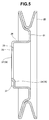
Fig. 5 is a sectional view of a pulley; -
Fig. 6 is a front view of the pulley; -
Fig. 7 is a rear view of the pulley; -
Fig. 8 is a rear view of a connecting member; and -
Fig. 9 is a sectional view taken along a line IX - IX inFig. 8 . - An electromagnetic clutch according to an embodiment of the present invention will now be described in detail with reference to
Figs. 1 to 9 . An electromagnetic clutch shown inFig. 1 is attached to aninput shaft 2 that extends in the left/right direction inFig. 1 . Here, an explanation will be made assuming that the distal end side (the right side inFig. 1 ) of theinput shaft 2 is the front side of anelectromagnetic clutch 1, and the opposite side as the rear side of theelectromagnetic clutch 1 for the descriptive convenience. - The
input shaft 2 is driven by a driving apparatus, for example, an engine (not shown) or a motor (not shown) and rotates. Aboss portion 4 of a rotor 3 (to be described later) is attached to theinput shaft 2. Theboss portion 4 includes aconcave portion 4a fitted in akey groove 2a of theinput shaft 2, and rotates integrally with theinput shaft 2 by key fitting. Acylindrical bearing collar 5 is welded to the distal end of theboss portion 4. In this embodiment, theinput shaft 2, theboss portion 4, and thebearing collar 5 form aninput shaft portion 6 that rotates upon receiving transmitted power. - The
rotor 3 includes adisc portion 7 that is fixed to the outer surface of theboss portion 4 and radially extends outward from theboss portion 4, and an innercylindrical portion 9 and an outercylindrical portion 10, which form, on the rear side of thedisc portion 7, anannular groove 8 opening to the rear side of theelectromagnetic clutch 1. Therotor 3 rotates integrally with theinput shaft portion 6. - A plurality of
arcuated slits 11 are formed in thedisc portion 7 of therotor 3. Theslits 11 extend in the circumferential direction of therotor 3 and extend through thedisc portion 7 in the axial direction of theinput shaft 2. Theslits 11 are arranged in pairs in the radial direction of thedisc portion 7 and formed at a plurality of portions in the circumferential direction of thedisc portion 7. Afield core 13 is supported, via a first bearing 12, by the rear end of the above-describedboss portion 4. - The
field core 13 is formed into an annular shape. Anannular groove 14 opening to the front side of theelectromagnetic clutch 1 is formed in thefield core 13. Anexciting coil 15 is stored in theannular groove 14. Theexciting coil 15 is fed bypower cables 15a derived from arear end face 13a (seeFig. 3 ) of thefield core 13. Thefield core 13 is inserted in theannular groove 8 of therotor 3. That is, thefield core 13 is arranged at a position on the rear side of the rotor 3 (on one side in the axial direction), where a magnetic flux Φ of theexciting coil 15 passes through therotor 3. - A pair of
locking members 16 for preventing thefield core 13 from rotating together with theinput shaft 2 are fixed to the rear end of thefield core 13 byrivets 17. Each of thelocking members 16 is formed by bending a rectangular metal plate material into a predetermined shape by press work. That is, as shown inFigs. 1 and3 , thelocking members 16 includeflat portions 16a extending in the radial direction of thefield core 13 along therear end face 13a of thefield core 13, and twoarm portions 16b (seeFig. 1 ) extending from the ends of theflat portions 16a in parallel to the axial direction of theinput shaft 2. - A
hole 19 used to insert a connectingmember 18 that connects thelocking member 16 and a fixed housing (not shown) is formed at each of the ends of theflat portions 16a. As shown inFig. 1 , the twoarm portions 16b are located outside in the radial direction of therotor 3 and project from therotor 3 to the front side of theelectromagnetic clutch 1. The distal end portion of eacharm portion 16b is bent outward in the radial direction of therotor 3 to form amounting plate 20. -
Braking plates 21 are attached to themounting plates 20 by mountingbolts 22, respectively. Rotation of thebraking plates 21 is also regulated like thefield core 13. Thebraking plates 21 are used to break anarmature 23 inserted between therotor 3 and thebraking plates 21 by a frictional resistance generated upon contact with the armature 23 (to be described later). As shown inFigs. 3 and4 , each thebraking plate 21 is formed into a shape that extends from thelocking member 16 in the circumferential direction of therotor 3. In addition, thebraking plates 21 are arranged on the front side of the rotor 3 (the other side in the axial direction), and an interval capable of inserting the armature 23 (to be described later) is formed between therotor 3 and thebraking plates 21, as shown inFig. 1 . In this embodiment, thebraking plate 21 corresponds to a "braking member" of the present invention. - As shown in
Figs. 1 and2 , asecond bearing 24 is provided at the front end of thebearing collar 5 welded to the front end of theboss portion 4 of therotor 3. Thesecond bearing 24 is provided on the front side of the rotor 3 (the other side in the axial direction) on theinput shaft portion 6. Thesecond bearing 24 corresponds to a "bearing" of the present invention. Acylindrical portion 26 of a pulley 25 (to be described later) is fitted on anouter ring 24a of thesecond bearing 24. That is, thepulley 25 is rotatably supported by theinput shaft portion 6 via thesecond bearing 24. Aninner ring 24b of thesecond bearing 24 is pressed backward from the front side by apress plate 27. Thepress plate 27 is pressed against theinner ring 24b by a fixingbolt 28 screwed into theinput shaft 2. - The
pulley 25 is a so-called steel pulley, and includes the above-describedcylindrical portion 26, apulley body 31 radially extending outward from the front end of thecylindrical portion 26, and aninner flange 32 connected to the rear end (one end in the axial direction) of thecylindrical portion 26, as shown inFigs. 1 ,2 , and5 . In this embodiment, thepulley 25 forms a "rotation transmission member" of the present invention. - A V belt (not shown) is looped over the
pulley body 31. Acaulking piece 33 is formed at the front end of thecylindrical portion 26 to prevent thepulley 25 from moving backward with respect to thesecond bearing 24. Thecaulking piece 33 is formed by making part of the inner surface of thecylindrical portion 26 radially project inward by press work, and pressed against the front end face of theouter ring 24a from the front side. - The
inner flange 32 has two functions. The first function is the function of regulating forward movement of thepulley 25 with respect to thesecond bearing 24. To implement the first function, theinner flange 32 is provided with a plurality ofabutment portions 34. As shown inFig. 7 , theabutment portions 34 are arranged at intervals in the rotation direction of thepulley 25. In this embodiment, theabutment portions 34 are provided at positions to equally divide thepulley 25 into three parts in the rotation direction. Theabutment portions 34 are formed by making part of the outer edge of theinner flange 32 and part of thecylindrical portion 26 partially plastically deform frontward by press. That is, theabutment portions 34 according to this embodiment are formed by plasticallydeformed portions 35 provided on theinner flange 32. - As shown in
Fig. 2 , theabutment portions 34 abut against theouter ring 24a of thesecond bearing 24 from behind (from the side of the rotor 3). That is, theinner flange 32 forms amovement regulating portion 36 that abuts against thesecond bearing 24 from the side of therotor 3 in the axial direction and regulates forward movement of thepulley 25. Theabutment portions 34 are formed on the outer periphery of theinner flange 32, thereby forming a plurality of concave portions 37 (seeFigs. 1 ,2 , and6 ). - Regions that are not used to implement the first function are formed between the
abutment portions 34 of theinner flange 32. These regions are called "non-effective portions 38". That is, theinner flange 32 includes a plurality ofnon-effective portions 38 located between theabutment portions 34 adjacent to each other in the rotation direction of thepulley 25. A throughhole 39 is formed in each of the plurality ofnon-effective portions 38. In this embodiment, the throughhole 39 corresponds to a "third hole" of the present invention. - The second function of the
inner flange 32 is the function of supporting the armature 23 (to be described later). To implement the second function, as shown inFigs. 1 and2 , a connectingmember 41 overlaid on the rear end face (the surface on the other side in the axial direction) of theinner flange 32 and a plurality offirst leaf springs 42 andsecond leaf springs 43 radially extending outward from the connectingmember 41 are used. - The
armature 23 is formed into an annular shape with a throughhole 23a at the center. Thearmature 23 is arranged between thedisc portion 7 of therotor 3 and thebraking plates 21 in a state in which theinput shaft portion 6 is inserted in the throughhole 23a, and supported by thefirst leaf springs 42 and thesecond leaf springs 43 so as to be movable in the axial direction. Thefirst leaf springs 42 and thesecond leaf springs 43 support thearmature 23 biased toward thebraking plates 21. Thefirst leaf springs 42 and thesecond leaf springs 43 according to this embodiment have the same shape. Each leaf spring is formed into a thin strip shape. In this embodiment, thefirst leaf spring 42 forms a "first spring member" of the present invention, and thesecond leaf spring 43 forms a "second spring member" of the present invention. - One-
end portions first leaf springs 42 and thesecond leaf springs 43 are attached to thearmature 23 byrivets 44. Other-end portions first leaf springs 42 and thesecond leaf springs 43 are attached to the connecting member 41 (to be described later) byfirst rivets 45 andsecond rivets 46, respectively. In this embodiment, thefirst rivet 45 and thesecond rivet 46 correspond to a "first fixing member" and a "second fixing member" of the present invention, respectively. Note that as the fixing member, not only a rivet but also a bolt, a nut, or a screw can be used. - The
armature 23 can move in the axial direction by a distance corresponding to an air gap G between thedisc portion 7 and thebraking plates 21 when thefirst leaf springs 42 and thesecond leaf springs 43 bend. As shown inFigs. 8 and 9 , the connectingmember 41 is formed into an annular plate shape. A plurality of first rivet insertion holes 47 and a plurality of second rivet insertion holes 48 are formed in the connectingmember 41. - The first rivet insertion holes 47 are each formed from a large-
diameter hole 47a and a small-diameter hole 47b, as shown inFig. 9 , and provided at positions to equally divide the connectingmember 41 into three parts in the circumferential direction, as shown inFig. 8 . More specifically, the first rivet insertion holes 47 are provided at positions facing the plurality ofabutment portions 34 of theinner flange 32, as shown inFig. 2 . In this embodiment, the firstrivet insertion hole 47 corresponds to a "first hole" of the present invention. - As shown in
Fig. 2 , thefirst rivets 45 are inserted into the first rivet insertion holes 47. The first rivets 45 extend through the connectingmember 41 and the other-end portions 42b of thefirst leaf springs 42, and fix the other-end portions 42b of thefirst leaf springs 42 to the rear surface of the connectingmember 41. That is, the other-end portions 42b of thefirst leaf springs 42 are attached to the connectingmember 41 by thefirst rivets 45 inserted into the first rivet insertion holes 47 and fixed to theinner flange 32 via the connectingmember 41. Proximal-side large-diameter portions 45a (front ends) of thefirst rivets 45 are stored in the large-diameter holes 47a of the first rivet insertion holes 47, and face the above-describedconcave portions 37 of theinner flange 32. - The second rivet insertion holes 48 are each formed from a through hole having a predetermined diameter, as shown in
Fig. 9 , and provided between the first rivet insertion holes 47 adjacent to each other at positions to equally divide the connectingmember 41 into three parts in the circumferential direction, as shown inFig. 8 . In addition, the second rivet insertion holes 48 are provided at positions (portions facing thenon-effective portions 38 of the inner flange 32) facing the throughholes 39 of the above-describedinner flange 32, as shown inFig. 2 . In this embodiment, the secondrivet insertion hole 48 corresponds to a "second hole" of the present invention. - The second rivets 46 are inserted into the second rivet insertion holes 48 and the through
holes 39 of theinner flange 32. The second rivets 46 extend through theinner flange 32, the connectingmember 41, and the other-end portions 43b of thesecond leaf springs 43, and fix the other-end portions 43b of thesecond leaf springs 43 and the connectingmember 41 to theinner flange 32. Exactly speaking, thesecond rivets 46 fix the connectingmember 41 to the rear surface of theinner flange 32, and also fix the other-end portions 43b of thesecond leaf springs 43 to the rear surface of the connectingmember 41. That is, the other-end portions 43b of thesecond leaf springs 43 are fixed to thenon-effective portions 38 of theinner flange 32 by a fixingstructure 49 including thesecond rivets 46 inserted into the second rivet insertion holes 48. The fixingstructure 49 according to this embodiment is formed from thesecond rivets 46 and the connectingmember 41. - The
first leaf springs 42 and thesecond leaf springs 43 are provided between thearmature 23 and the connectingmember 41 in a state in which they tilt with respect to the radial direction of thepulley 25 viewed from the front side, as shown inFig. 4 . Thefirst leaf springs 42 are arranged at positions to equally divide thepulley 25 into three parts in the rotation direction. Thesecond leaf springs 43 are located between pairs offirst leaf springs 42 adjacent to each other. - In the
electromagnetic clutch 1 having the above-described arrangement, when theexciting coil 15 is excited, thearmature 23 is magnetically attracted by therotor 3 and rotates integrally with therotor 3.
The rotation of thearmature 23 is transmitted to thepulley 25 via thefirst leaf springs 42, thesecond leaf springs 43, and the connectingmember 41. For this reason, power is transmitted from theinput shaft 2 to thepulley 25 via theelectromagnetic clutch 1. - When the
exciting coil 15 changes to a non-excitation state, thearmature 23 is separated from therotor 3 by the spring force of thefirst leaf springs 42 and thesecond leaf springs 43 and pressed against thebraking plates 21. When thearmature 23 is pressed against thebraking plates 21 in this way, a braking force is generated, and thepulley 25 that is inertially rotating is stopped and held in the stop state. The magnitudes of the braking force and the force to hold thepulley 25 in the stop state depend on the magnitude of the spring force of thefirst leaf springs 42 and the second leaf springs 43. - In this embodiment, the other-
end portions 42b of thefirst leaf springs 42 are fixed to the connectingmember 41 at positions corresponding to theabutment portions 34 provided on theinner flange 32 of thepulley 25. For this reason, when fixing the other-end portions first leaf springs 42 and thesecond leaf springs 43 to theinner flange 32, attachable positions are not restricted by theabutment portions 34 of theinner flange 32. According to theelectromagnetic clutch 1 having the above-described arrangement, the number of spring members that bias thearmature 23 against thebraking plates 21 increases by the number offirst leaf springs 42, as compared to, for example, the electromagnetic clutch described in the literature. Hence, according to this embodiment, since the number of spring members that bias thearmature 23 can be increased, the braking force and the holding force to hold the standstill state can be increased. - The
pulley 25 according to this embodiment includes thecylindrical portion 26 in which thesecond bearing 24 is fitted, and theinner flange 32 radially extending inward from thecylindrical portion 26 and forming themovement regulating portion 36. Theabutment portions 34 are formed from the plasticallydeformed portions 35 that are formed by making part of theinner flange 32 project toward thesecond bearing 24. The proximal-side large-diameter portions 45a as one-end portions of thefirst rivets 45 face theconcave portions 37 made by forming theabutment portions 34 on theinner flange 32. It is therefore possible to form thepulley 25 using thesteel pulley 25 and reduce the weight of thepulley 25. Hence, the time until thepulley 25 stops can be shortened without changing the spring force of thefirst leaf springs 42 and thesecond leaf springs 43 and the arrangement of thebraking plates 21. - The other-
end portions 43b of thesecond leaf springs 43 according to the above-described embodiment are fixed to theinner flange 32 via the connectingmember 41. It is therefore possible to form thefirst leaf springs 42 and thesecond leaf springs 43 into the same shape and reduce the cost.
Claims (4)
- An electromagnetic clutch (1) characterized by comprising:an input shaft portion (6) that rotates upon receiving transmitted power;a rotor (3) that radially extends outward from the input shaft portion (6) and rotates integrally with the input shaft portion (6);a field core (13) that includes an exciting coil (15) and is provided at a position where a magnetic flux of the exciting coil (15) passes through the rotor (3) on one side of the rotor (3) in an axial direction in a state in which rotation is regulated;a braking member (21) arranged on the other side of the rotor (3) in the axial direction in the state in which rotation is regulated;a bearing (24) provided on the other side of the rotor (3) in the axial direction on the input shaft portion (6);a rotation transmission member (25) that includes a movement regulating portion (36) that abuts against the bearing (24) from a side of the rotor (3) and regulates movement of the rotation transmission member (25) to the one side in the axial direction and is rotatably supported by the input shaft portion (6) via the bearing (24), the movement regulating portion (36) including a plurality of abutment portions (34) that are formed at intervals in a rotation direction of the rotation transmission member (25) and abut against the bearing (24);a connecting member (41) that is overlaid on one surface of the movement regulating portion (36) in the axial direction, the connecting member (41) including a plurality of first holes (47) respectively provided at portions facing the plurality of abutment portions (34) and a plurality of second holes (48) provided at portions facing regions (38) between the plurality of abutment portions (34);an armature (23) that is formed into an annular shape with a through hole (23a) at a center and arranged between the rotor (3) and the braking member (21) in a state in which the input shaft portion (6) is inserted in the through hole (23a), and is movable in the axial direction by a distance corresponding to an air gap;a plurality of first spring members (42) and a plurality of second spring members (43) which include one-end portions (42a, 43a) attached to the armature (23) and other-end portions (42b, 43b) and support the armature (23) while biasing the armature (23) toward the braking member (21);a plurality of first fixing members (45) that are inserted into the plurality of first holes (47) of the connecting member (41), respectively, and fix the other-end portions (42b) of the plurality of first spring members (42) to the connecting member (41); anda plurality of second fixing members (46) that are inserted into the plurality of second holes (48) of the connecting member (41), respectively, and fix the other-end portions (43b) of the plurality of second spring members (43) and the connecting member (41) to the regions (38) of the movement regulating portion (36).
- The electromagnetic clutch (1) according to claim 1, wherein the rotation transmission member (25) further includes a cylindrical portion (26) in which the bearing (24) is fitted,
the movement regulating portion (36) is formed from an inner flange (32) radially extending inward from the cylindrical portion (26),
each of the abutment portions (34) is formed from a plastically deformed portion (35) formed by making part of the inner flange (32) project toward the bearing (24), and
a one-end portion of each of the first fixing members (45) faces a concave portion (37) made by forming the abutment portion (34) on the inner flange (32). - The electromagnetic clutch (1) according to claim 1, wherein the movement regulating portion (36) further includes a plurality of third holes (39) provided in the regions (38), and
the plurality of second fixing members (46) are inserted into the plurality of second holes (48) and the plurality of third holes (39). - The electromagnetic clutch (1) according to claim 1, wherein each of the plurality of first fixing members (45) and the plurality of second fixing members (46) is formed from a rivet.
Applications Claiming Priority (1)
| Application Number | Priority Date | Filing Date | Title |
|---|---|---|---|
| JP2015059467A JP6402057B2 (en) | 2015-03-23 | 2015-03-23 | Electromagnetic clutch |
Publications (3)
| Publication Number | Publication Date |
|---|---|
| EP3073143A2 true EP3073143A2 (en) | 2016-09-28 |
| EP3073143A3 EP3073143A3 (en) | 2016-10-05 |
| EP3073143B1 EP3073143B1 (en) | 2017-09-13 |
Family
ID=55542480
Family Applications (1)
| Application Number | Title | Priority Date | Filing Date |
|---|---|---|---|
| EP16160566.2A Not-in-force EP3073143B1 (en) | 2015-03-23 | 2016-03-16 | Electromagnetic clutch |
Country Status (4)
| Country | Link |
|---|---|
| US (1) | US9631688B2 (en) |
| EP (1) | EP3073143B1 (en) |
| JP (1) | JP6402057B2 (en) |
| CN (1) | CN105987095B (en) |
Cited By (1)
| Publication number | Priority date | Publication date | Assignee | Title |
|---|---|---|---|---|
| CN113195917A (en) * | 2018-12-04 | 2021-07-30 | 敏思工业公司 | Electromagnetic system for controlling the operating mode of a non-friction coupling assembly, and coupling and magnetic control assembly having such an electromagnetic system |
Families Citing this family (2)
| Publication number | Priority date | Publication date | Assignee | Title |
|---|---|---|---|---|
| JP6857967B2 (en) * | 2016-04-05 | 2021-04-14 | 小倉クラッチ株式会社 | Seal structure of lead wire for electromagnet |
| US10883552B2 (en) * | 2019-04-10 | 2021-01-05 | Warner Electric Technology Llc | Rotational coupling device with flux conducting bearing shield |
Citations (1)
| Publication number | Priority date | Publication date | Assignee | Title |
|---|---|---|---|---|
| JP2013234723A (en) | 2012-05-10 | 2013-11-21 | Ogura Clutch Co Ltd | Electromagnetic clutch |
Family Cites Families (8)
| Publication number | Priority date | Publication date | Assignee | Title |
|---|---|---|---|---|
| US3082933A (en) * | 1960-12-16 | 1963-03-26 | Gen Motors Corp | Electromagnetic clutch |
| JPS5947538A (en) * | 1982-09-10 | 1984-03-17 | Shinko Electric Co Ltd | Solenoid clutch-brake |
| JPS59133840A (en) * | 1983-01-21 | 1984-08-01 | Ogura Clutch Co Ltd | Electromagnetic clutch and brake |
| US5119918A (en) * | 1991-10-11 | 1992-06-09 | Dana Corporation | Electromagnetic clutch with permanent magnet brake |
| US5971121A (en) * | 1998-04-30 | 1999-10-26 | Pardee; James Alain | Mag stop clutch with center pole |
| DE10059747A1 (en) * | 2000-12-01 | 2002-06-06 | Hilti Ag | Electric hand tool with safety clutch |
| US7732959B2 (en) * | 2005-06-10 | 2010-06-08 | Warner Electric Technology, Llc | Rotational coupling device |
| DE102012221369A1 (en) * | 2012-11-22 | 2014-05-22 | Schaeffler Technologies Gmbh & Co. Kg | roller bearing |
-
2015
- 2015-03-23 JP JP2015059467A patent/JP6402057B2/en active Active
-
2016
- 2016-03-16 EP EP16160566.2A patent/EP3073143B1/en not_active Not-in-force
- 2016-03-21 US US15/076,262 patent/US9631688B2/en active Active
- 2016-03-23 CN CN201610168110.8A patent/CN105987095B/en not_active Expired - Fee Related
Patent Citations (1)
| Publication number | Priority date | Publication date | Assignee | Title |
|---|---|---|---|---|
| JP2013234723A (en) | 2012-05-10 | 2013-11-21 | Ogura Clutch Co Ltd | Electromagnetic clutch |
Cited By (1)
| Publication number | Priority date | Publication date | Assignee | Title |
|---|---|---|---|---|
| CN113195917A (en) * | 2018-12-04 | 2021-07-30 | 敏思工业公司 | Electromagnetic system for controlling the operating mode of a non-friction coupling assembly, and coupling and magnetic control assembly having such an electromagnetic system |
Also Published As
| Publication number | Publication date |
|---|---|
| CN105987095A (en) | 2016-10-05 |
| EP3073143A3 (en) | 2016-10-05 |
| JP2016180415A (en) | 2016-10-13 |
| JP6402057B2 (en) | 2018-10-10 |
| US20160281809A1 (en) | 2016-09-29 |
| EP3073143B1 (en) | 2017-09-13 |
| CN105987095B (en) | 2018-08-21 |
| US9631688B2 (en) | 2017-04-25 |
Similar Documents
| Publication | Publication Date | Title |
|---|---|---|
| EP3073143B1 (en) | Electromagnetic clutch | |
| US5119915A (en) | Electromagnetic coupling armature assembly with flux isolator springs | |
| EP2952767B1 (en) | Rotation transmission device | |
| US20120111690A1 (en) | Electromagnetic clutch | |
| US7604105B2 (en) | Rotation transmission device | |
| EP3141772B1 (en) | Electromagnetic clutch | |
| JP6684187B2 (en) | Electromagnetic clutch | |
| JP2013234723A (en) | Electromagnetic clutch | |
| US8973727B1 (en) | Electromagnetic clutch | |
| US6343680B1 (en) | Friction clutch | |
| EP3550167B1 (en) | Electromagnetic connecting device | |
| JP5509052B2 (en) | Electromagnetic clutch | |
| JP4541178B2 (en) | Rotation transmission device | |
| JP2006226366A (en) | Rotation transmission device | |
| JP2006226350A (en) | Rotation transmission device | |
| JP2011112060A (en) | Electromagnetic connecting device | |
| JPH0642105Y2 (en) | Electromagnetic coupling device | |
| JP2006233847A (en) | Electromagnetic clutch of compressor | |
| JP2005054907A (en) | Non-excitation actuated type electromagnetic brake | |
| JP2007187246A (en) | Rotation transmitting device | |
| JPH0126907Y2 (en) | ||
| JPH0236979Y2 (en) | ||
| JPH03107621A (en) | Magnetic connecting device | |
| JP2011163515A (en) | Electromagnetic coupling device | |
| JP2001032857A (en) | Electromagnetic connecting device |
Legal Events
| Date | Code | Title | Description |
|---|---|---|---|
| PUAI | Public reference made under article 153(3) epc to a published international application that has entered the european phase |
Free format text: ORIGINAL CODE: 0009012 |
|
| PUAL | Search report despatched |
Free format text: ORIGINAL CODE: 0009013 |
|
| AK | Designated contracting states |
Kind code of ref document: A2 Designated state(s): AL AT BE BG CH CY CZ DE DK EE ES FI FR GB GR HR HU IE IS IT LI LT LU LV MC MK MT NL NO PL PT RO RS SE SI SK SM TR |
|
| AX | Request for extension of the european patent |
Extension state: BA ME |
|
| AK | Designated contracting states |
Kind code of ref document: A3 Designated state(s): AL AT BE BG CH CY CZ DE DK EE ES FI FR GB GR HR HU IE IS IT LI LT LU LV MC MK MT NL NO PL PT RO RS SE SI SK SM TR |
|
| AX | Request for extension of the european patent |
Extension state: BA ME |
|
| RIC1 | Information provided on ipc code assigned before grant |
Ipc: F16D 67/06 20060101ALI20160830BHEP Ipc: F16D 27/112 20060101AFI20160830BHEP Ipc: F16D 27/00 20060101ALN20160830BHEP |
|
| STAA | Information on the status of an ep patent application or granted ep patent |
Free format text: STATUS: REQUEST FOR EXAMINATION WAS MADE |
|
| 17P | Request for examination filed |
Effective date: 20161130 |
|
| RBV | Designated contracting states (corrected) |
Designated state(s): AL AT BE BG CH CY CZ DE DK EE ES FI FR GB GR HR HU IE IS IT LI LT LU LV MC MK MT NL NO PL PT RO RS SE SI SK SM TR |
|
| GRAP | Despatch of communication of intention to grant a patent |
Free format text: ORIGINAL CODE: EPIDOSNIGR1 |
|
| STAA | Information on the status of an ep patent application or granted ep patent |
Free format text: STATUS: GRANT OF PATENT IS INTENDED |
|
| RIC1 | Information provided on ipc code assigned before grant |
Ipc: F16D 27/00 20060101ALN20170317BHEP Ipc: F16D 67/06 20060101ALI20170317BHEP Ipc: F16D 27/112 20060101AFI20170317BHEP |
|
| INTG | Intention to grant announced |
Effective date: 20170405 |
|
| GRAS | Grant fee paid |
Free format text: ORIGINAL CODE: EPIDOSNIGR3 |
|
| GRAA | (expected) grant |
Free format text: ORIGINAL CODE: 0009210 |
|
| STAA | Information on the status of an ep patent application or granted ep patent |
Free format text: STATUS: THE PATENT HAS BEEN GRANTED |
|
| AK | Designated contracting states |
Kind code of ref document: B1 Designated state(s): AL AT BE BG CH CY CZ DE DK EE ES FI FR GB GR HR HU IE IS IT LI LT LU LV MC MK MT NL NO PL PT RO RS SE SI SK SM TR |
|
| REG | Reference to a national code |
Ref country code: GB Ref legal event code: FG4D |
|
| REG | Reference to a national code |
Ref country code: CH Ref legal event code: EP |
|
| REG | Reference to a national code |
Ref country code: IE Ref legal event code: FG4D |
|
| REG | Reference to a national code |
Ref country code: AT Ref legal event code: REF Ref document number: 928464 Country of ref document: AT Kind code of ref document: T Effective date: 20171015 |
|
| REG | Reference to a national code |
Ref country code: DE Ref legal event code: R096 Ref document number: 602016000368 Country of ref document: DE |
|
| REG | Reference to a national code |
Ref country code: NL Ref legal event code: MP Effective date: 20170913 |
|
| REG | Reference to a national code |
Ref country code: LT Ref legal event code: MG4D |
|
| PG25 | Lapsed in a contracting state [announced via postgrant information from national office to epo] |
Ref country code: SE Free format text: LAPSE BECAUSE OF FAILURE TO SUBMIT A TRANSLATION OF THE DESCRIPTION OR TO PAY THE FEE WITHIN THE PRESCRIBED TIME-LIMIT Effective date: 20170913 Ref country code: FI Free format text: LAPSE BECAUSE OF FAILURE TO SUBMIT A TRANSLATION OF THE DESCRIPTION OR TO PAY THE FEE WITHIN THE PRESCRIBED TIME-LIMIT Effective date: 20170913 Ref country code: NO Free format text: LAPSE BECAUSE OF FAILURE TO SUBMIT A TRANSLATION OF THE DESCRIPTION OR TO PAY THE FEE WITHIN THE PRESCRIBED TIME-LIMIT Effective date: 20171213 Ref country code: HR Free format text: LAPSE BECAUSE OF FAILURE TO SUBMIT A TRANSLATION OF THE DESCRIPTION OR TO PAY THE FEE WITHIN THE PRESCRIBED TIME-LIMIT Effective date: 20170913 Ref country code: LT Free format text: LAPSE BECAUSE OF FAILURE TO SUBMIT A TRANSLATION OF THE DESCRIPTION OR TO PAY THE FEE WITHIN THE PRESCRIBED TIME-LIMIT Effective date: 20170913 |
|
| REG | Reference to a national code |
Ref country code: AT Ref legal event code: MK05 Ref document number: 928464 Country of ref document: AT Kind code of ref document: T Effective date: 20170913 |
|
| PG25 | Lapsed in a contracting state [announced via postgrant information from national office to epo] |
Ref country code: RS Free format text: LAPSE BECAUSE OF FAILURE TO SUBMIT A TRANSLATION OF THE DESCRIPTION OR TO PAY THE FEE WITHIN THE PRESCRIBED TIME-LIMIT Effective date: 20170913 Ref country code: GR Free format text: LAPSE BECAUSE OF FAILURE TO SUBMIT A TRANSLATION OF THE DESCRIPTION OR TO PAY THE FEE WITHIN THE PRESCRIBED TIME-LIMIT Effective date: 20171214 Ref country code: BG Free format text: LAPSE BECAUSE OF FAILURE TO SUBMIT A TRANSLATION OF THE DESCRIPTION OR TO PAY THE FEE WITHIN THE PRESCRIBED TIME-LIMIT Effective date: 20171213 Ref country code: LV Free format text: LAPSE BECAUSE OF FAILURE TO SUBMIT A TRANSLATION OF THE DESCRIPTION OR TO PAY THE FEE WITHIN THE PRESCRIBED TIME-LIMIT Effective date: 20170913 Ref country code: ES Free format text: LAPSE BECAUSE OF FAILURE TO SUBMIT A TRANSLATION OF THE DESCRIPTION OR TO PAY THE FEE WITHIN THE PRESCRIBED TIME-LIMIT Effective date: 20170913 |
|
| PG25 | Lapsed in a contracting state [announced via postgrant information from national office to epo] |
Ref country code: NL Free format text: LAPSE BECAUSE OF FAILURE TO SUBMIT A TRANSLATION OF THE DESCRIPTION OR TO PAY THE FEE WITHIN THE PRESCRIBED TIME-LIMIT Effective date: 20170913 |
|
| PG25 | Lapsed in a contracting state [announced via postgrant information from national office to epo] |
Ref country code: CZ Free format text: LAPSE BECAUSE OF FAILURE TO SUBMIT A TRANSLATION OF THE DESCRIPTION OR TO PAY THE FEE WITHIN THE PRESCRIBED TIME-LIMIT Effective date: 20170913 Ref country code: RO Free format text: LAPSE BECAUSE OF FAILURE TO SUBMIT A TRANSLATION OF THE DESCRIPTION OR TO PAY THE FEE WITHIN THE PRESCRIBED TIME-LIMIT Effective date: 20170913 Ref country code: PL Free format text: LAPSE BECAUSE OF FAILURE TO SUBMIT A TRANSLATION OF THE DESCRIPTION OR TO PAY THE FEE WITHIN THE PRESCRIBED TIME-LIMIT Effective date: 20170913 |
|
| PG25 | Lapsed in a contracting state [announced via postgrant information from national office to epo] |
Ref country code: SK Free format text: LAPSE BECAUSE OF FAILURE TO SUBMIT A TRANSLATION OF THE DESCRIPTION OR TO PAY THE FEE WITHIN THE PRESCRIBED TIME-LIMIT Effective date: 20170913 Ref country code: SM Free format text: LAPSE BECAUSE OF FAILURE TO SUBMIT A TRANSLATION OF THE DESCRIPTION OR TO PAY THE FEE WITHIN THE PRESCRIBED TIME-LIMIT Effective date: 20170913 Ref country code: IS Free format text: LAPSE BECAUSE OF FAILURE TO SUBMIT A TRANSLATION OF THE DESCRIPTION OR TO PAY THE FEE WITHIN THE PRESCRIBED TIME-LIMIT Effective date: 20180113 Ref country code: AT Free format text: LAPSE BECAUSE OF FAILURE TO SUBMIT A TRANSLATION OF THE DESCRIPTION OR TO PAY THE FEE WITHIN THE PRESCRIBED TIME-LIMIT Effective date: 20170913 Ref country code: EE Free format text: LAPSE BECAUSE OF FAILURE TO SUBMIT A TRANSLATION OF THE DESCRIPTION OR TO PAY THE FEE WITHIN THE PRESCRIBED TIME-LIMIT Effective date: 20170913 |
|
| REG | Reference to a national code |
Ref country code: DE Ref legal event code: R097 Ref document number: 602016000368 Country of ref document: DE |
|
| PLBE | No opposition filed within time limit |
Free format text: ORIGINAL CODE: 0009261 |
|
| STAA | Information on the status of an ep patent application or granted ep patent |
Free format text: STATUS: NO OPPOSITION FILED WITHIN TIME LIMIT |
|
| PG25 | Lapsed in a contracting state [announced via postgrant information from national office to epo] |
Ref country code: DK Free format text: LAPSE BECAUSE OF FAILURE TO SUBMIT A TRANSLATION OF THE DESCRIPTION OR TO PAY THE FEE WITHIN THE PRESCRIBED TIME-LIMIT Effective date: 20170913 |
|
| 26N | No opposition filed |
Effective date: 20180614 |
|
| PG25 | Lapsed in a contracting state [announced via postgrant information from national office to epo] |
Ref country code: MC Free format text: LAPSE BECAUSE OF FAILURE TO SUBMIT A TRANSLATION OF THE DESCRIPTION OR TO PAY THE FEE WITHIN THE PRESCRIBED TIME-LIMIT Effective date: 20170913 Ref country code: SI Free format text: LAPSE BECAUSE OF FAILURE TO SUBMIT A TRANSLATION OF THE DESCRIPTION OR TO PAY THE FEE WITHIN THE PRESCRIBED TIME-LIMIT Effective date: 20170913 |
|
| REG | Reference to a national code |
Ref country code: BE Ref legal event code: MM Effective date: 20180331 |
|
| REG | Reference to a national code |
Ref country code: IE Ref legal event code: MM4A |
|
| PG25 | Lapsed in a contracting state [announced via postgrant information from national office to epo] |
Ref country code: LU Free format text: LAPSE BECAUSE OF NON-PAYMENT OF DUE FEES Effective date: 20180316 |
|
| PG25 | Lapsed in a contracting state [announced via postgrant information from national office to epo] |
Ref country code: IE Free format text: LAPSE BECAUSE OF NON-PAYMENT OF DUE FEES Effective date: 20180316 |
|
| PG25 | Lapsed in a contracting state [announced via postgrant information from national office to epo] |
Ref country code: BE Free format text: LAPSE BECAUSE OF NON-PAYMENT OF DUE FEES Effective date: 20180331 |
|
| PG25 | Lapsed in a contracting state [announced via postgrant information from national office to epo] |
Ref country code: FR Free format text: LAPSE BECAUSE OF NON-PAYMENT OF DUE FEES Effective date: 20180331 |
|
| PGFP | Annual fee paid to national office [announced via postgrant information from national office to epo] |
Ref country code: IT Payment date: 20190331 Year of fee payment: 4 Ref country code: DE Payment date: 20190331 Year of fee payment: 4 |
|
| REG | Reference to a national code |
Ref country code: CH Ref legal event code: PL |
|
| PG25 | Lapsed in a contracting state [announced via postgrant information from national office to epo] |
Ref country code: CH Free format text: LAPSE BECAUSE OF NON-PAYMENT OF DUE FEES Effective date: 20190331 Ref country code: LI Free format text: LAPSE BECAUSE OF NON-PAYMENT OF DUE FEES Effective date: 20190331 Ref country code: MT Free format text: LAPSE BECAUSE OF NON-PAYMENT OF DUE FEES Effective date: 20180316 |
|
| PG25 | Lapsed in a contracting state [announced via postgrant information from national office to epo] |
Ref country code: TR Free format text: LAPSE BECAUSE OF FAILURE TO SUBMIT A TRANSLATION OF THE DESCRIPTION OR TO PAY THE FEE WITHIN THE PRESCRIBED TIME-LIMIT Effective date: 20170913 |
|
| PG25 | Lapsed in a contracting state [announced via postgrant information from national office to epo] |
Ref country code: PT Free format text: LAPSE BECAUSE OF FAILURE TO SUBMIT A TRANSLATION OF THE DESCRIPTION OR TO PAY THE FEE WITHIN THE PRESCRIBED TIME-LIMIT Effective date: 20170913 |
|
| PG25 | Lapsed in a contracting state [announced via postgrant information from national office to epo] |
Ref country code: HU Free format text: LAPSE BECAUSE OF FAILURE TO SUBMIT A TRANSLATION OF THE DESCRIPTION OR TO PAY THE FEE WITHIN THE PRESCRIBED TIME-LIMIT; INVALID AB INITIO Effective date: 20160316 Ref country code: MK Free format text: LAPSE BECAUSE OF NON-PAYMENT OF DUE FEES Effective date: 20170913 Ref country code: CY Free format text: LAPSE BECAUSE OF FAILURE TO SUBMIT A TRANSLATION OF THE DESCRIPTION OR TO PAY THE FEE WITHIN THE PRESCRIBED TIME-LIMIT Effective date: 20170913 |
|
| PG25 | Lapsed in a contracting state [announced via postgrant information from national office to epo] |
Ref country code: AL Free format text: LAPSE BECAUSE OF FAILURE TO SUBMIT A TRANSLATION OF THE DESCRIPTION OR TO PAY THE FEE WITHIN THE PRESCRIBED TIME-LIMIT Effective date: 20170913 |
|
| REG | Reference to a national code |
Ref country code: DE Ref legal event code: R119 Ref document number: 602016000368 Country of ref document: DE |
|
| PG25 | Lapsed in a contracting state [announced via postgrant information from national office to epo] |
Ref country code: DE Free format text: LAPSE BECAUSE OF NON-PAYMENT OF DUE FEES Effective date: 20201001 |
|
| GBPC | Gb: european patent ceased through non-payment of renewal fee |
Effective date: 20200316 |
|
| PG25 | Lapsed in a contracting state [announced via postgrant information from national office to epo] |
Ref country code: GB Free format text: LAPSE BECAUSE OF NON-PAYMENT OF DUE FEES Effective date: 20200316 |
|
| PG25 | Lapsed in a contracting state [announced via postgrant information from national office to epo] |
Ref country code: IT Free format text: LAPSE BECAUSE OF NON-PAYMENT OF DUE FEES Effective date: 20200316 |