EP3141772B1 - Electromagnetic clutch - Google Patents
Electromagnetic clutch Download PDFInfo
- Publication number
- EP3141772B1 EP3141772B1 EP16187456.5A EP16187456A EP3141772B1 EP 3141772 B1 EP3141772 B1 EP 3141772B1 EP 16187456 A EP16187456 A EP 16187456A EP 3141772 B1 EP3141772 B1 EP 3141772B1
- Authority
- EP
- European Patent Office
- Prior art keywords
- armature
- base
- rotary member
- leaf spring
- flange
- Prior art date
- Legal status (The legal status is an assumption and is not a legal conclusion. Google has not performed a legal analysis and makes no representation as to the accuracy of the status listed.)
- Active
Links
- 239000000696 magnetic material Substances 0.000 claims description 4
- 230000004907 flux Effects 0.000 claims description 3
- 230000005855 radiation Effects 0.000 description 5
- 230000005540 biological transmission Effects 0.000 description 2
- 239000012141 concentrate Substances 0.000 description 2
- 239000000463 material Substances 0.000 description 2
- 238000005336 cracking Methods 0.000 description 1
- 230000007423 decrease Effects 0.000 description 1
- 230000001419 dependent effect Effects 0.000 description 1
- 230000005281 excited state Effects 0.000 description 1
- 230000005389 magnetism Effects 0.000 description 1
- 238000004080 punching Methods 0.000 description 1
- 230000001105 regulatory effect Effects 0.000 description 1
- 239000011347 resin Substances 0.000 description 1
- 229920005989 resin Polymers 0.000 description 1
Images


Classifications
-
- F—MECHANICAL ENGINEERING; LIGHTING; HEATING; WEAPONS; BLASTING
- F16—ENGINEERING ELEMENTS AND UNITS; GENERAL MEASURES FOR PRODUCING AND MAINTAINING EFFECTIVE FUNCTIONING OF MACHINES OR INSTALLATIONS; THERMAL INSULATION IN GENERAL
- F16D—COUPLINGS FOR TRANSMITTING ROTATION; CLUTCHES; BRAKES
- F16D27/00—Magnetically- or electrically- actuated clutches; Control or electric circuits therefor
- F16D27/02—Magnetically- or electrically- actuated clutches; Control or electric circuits therefor with electromagnets incorporated in the clutch, i.e. with collecting rings
-
- F—MECHANICAL ENGINEERING; LIGHTING; HEATING; WEAPONS; BLASTING
- F16—ENGINEERING ELEMENTS AND UNITS; GENERAL MEASURES FOR PRODUCING AND MAINTAINING EFFECTIVE FUNCTIONING OF MACHINES OR INSTALLATIONS; THERMAL INSULATION IN GENERAL
- F16D—COUPLINGS FOR TRANSMITTING ROTATION; CLUTCHES; BRAKES
- F16D27/00—Magnetically- or electrically- actuated clutches; Control or electric circuits therefor
- F16D27/10—Magnetically- or electrically- actuated clutches; Control or electric circuits therefor with an electromagnet not rotating with a clutching member, i.e. without collecting rings
- F16D27/108—Magnetically- or electrically- actuated clutches; Control or electric circuits therefor with an electromagnet not rotating with a clutching member, i.e. without collecting rings with axially movable clutching members
- F16D27/112—Magnetically- or electrically- actuated clutches; Control or electric circuits therefor with an electromagnet not rotating with a clutching member, i.e. without collecting rings with axially movable clutching members with flat friction surfaces, e.g. discs
-
- F—MECHANICAL ENGINEERING; LIGHTING; HEATING; WEAPONS; BLASTING
- F16—ENGINEERING ELEMENTS AND UNITS; GENERAL MEASURES FOR PRODUCING AND MAINTAINING EFFECTIVE FUNCTIONING OF MACHINES OR INSTALLATIONS; THERMAL INSULATION IN GENERAL
- F16D—COUPLINGS FOR TRANSMITTING ROTATION; CLUTCHES; BRAKES
- F16D27/00—Magnetically- or electrically- actuated clutches; Control or electric circuits therefor
- F16D27/14—Details
-
- F—MECHANICAL ENGINEERING; LIGHTING; HEATING; WEAPONS; BLASTING
- F16—ENGINEERING ELEMENTS AND UNITS; GENERAL MEASURES FOR PRODUCING AND MAINTAINING EFFECTIVE FUNCTIONING OF MACHINES OR INSTALLATIONS; THERMAL INSULATION IN GENERAL
- F16D—COUPLINGS FOR TRANSMITTING ROTATION; CLUTCHES; BRAKES
- F16D27/00—Magnetically- or electrically- actuated clutches; Control or electric circuits therefor
- F16D2027/007—Bias of an armature of an electromagnetic clutch by flexing of substantially flat springs, e.g. leaf springs
Definitions
- the present invention relates to an electromagnetic clutch according to the preamble of claim 1.
- the present invention relates to an electromagnetic clutch including a single leaf spring having a function of causing an armature hub to support an armature while biasing the armature away from a rotor, and a function of regulating the movement of the armature in a non-excited state.
- An electromagnetic clutch of the above-mentioned type is known, e.g., from EP 0 836 026 A1 , US 2004/0016617 A1 and EP 0 841 497 A2 . Furthermore, a related electromagnetic clutch is disclosed in Japanese Utility Model Publication No. 61-37862 (literature 1).
- This electromagnetic clutch includes an annular rotor as an input-side rotary member. A field having an electromagnetic coil is inserted inside the rotor. An input shaft of a device to be driven is inserted into the axial portion of the rotor. An armature hub is formed on a distal end portion of the input shaft. A leaf spring extending in the radial direction of the rotor is fixed to the armature hub by rivets.
- An armature is fixed to the end portion of the leaf spring on the outside of the rotor in the radial direction.
- the leaf spring biases the armature away from the rotor.
- the armature is formed into an annular shape when viewed in the axial direction of the input shaft.
- the armature is supported by the armature hub via the leaf spring, thereby being held in a position facing the end face of the rotor in the axial direction.
- the leaf spring includes an annular main body having an annular shape when viewed in the axial direction of the above-described input shaft, and a stopper projecting inside the annular main body.
- the annular main body is formed into a non-circular shape which is axially symmetrical with respect to a virtual central line extending in the radial direction of the rotor, when viewed in the axial direction of the input shaft.
- the annular main body includes a proximal end portion intersecting the virtual central line inside the rotor in the radial direction, and a free end portion intersecting the virtual central line inside the rotor in the radial direction.
- the proximal end portion is fixed to the armature hub by a rivet.
- the free end portion is fixed to the armature by a rivet.
- the stopper includes a tongue projecting from the proximal end portion to the free end portion of the annular main body. Stopper rubber member is formed at the distal end portion of the tongue.
- the stopper rubber member is formed in the stopper of the leaf spring, the outside dimension (outer diameter) of a flange of the armature hub in the radial direction can be made smaller than the inside dimension (inner diameter) of the armature in the radial direction. Consequently, an inexpensive lightweight electromagnetic clutch can be provided.
- the outer diameter of the flange of the armature hub is smaller than the inner diameter of the armature, the armature is not supported by the flange of the armature hub. Consequently, the armature and leaf spring are spun off and fall outside the electromagnetic clutch as described above.
- an inexpensive lightweight electromagnetic clutch can be provided by forming the stopper rubber member in the stopper of the leaf spring. On the other hand, if the proximal end portion of the leaf spring is broken in the periphery of the rivet hole, the rotating armature and leaf spring may be spun off and fall outside the electromagnetic clutch.
- an object of the present invention to provide an electromagnetic clutch which prevents an armature from falling outside the electromagnetic clutch even when a leaf spring is broken by the application of an excess load.
- an electromagnetic clutch having the features of claim 1. Further embodiments of the invention are described in the dependent claims.
- the electromagnetic clutch of the present invention includes a first rotary member formed of a magnetic material; a second rotary member arranged in an axial portion of the first rotary member, and rotatable with respect to the first rotary member; an armature hub including a boss formed on one end portion of the second rotary member in an axial direction, and a flange extending outside in a radial direction from the boss; an armature formed into an annular shape including a hollow portion having a diameter larger than an outer diameter of the flange, and arranged in a position facing one end portion of the first rotary member in the axial direction, the flange being inserted into the hollow portion; a single leaf spring configured to connect the armature to the flange, and bias the armature away from the first rotary member by a spring force; an electromagnetic coil configured to generate a magnetic flux, and magnetically attract the armature to the first rotary member against the spring force of the leaf spring; a plurality of first rivets configured to fix the leaf spring to the
- An electromagnetic clutch as an embodiment of the present invention will be explained in detail below with reference to Figs. 1 to 3 .
- An electromagnetic clutch 1 shown in Fig. 1 switches a connected state in which the rotation of a rotor 2 depicted on the outermost side in Fig. 1 is transmitted to a rotating shaft 3 (see Fig. 2 ) arranged in the axial portion of the rotor 2, and a disconnected state in which this power transmission is interrupted.
- the rotor 2 is formed into an annular shape by using a magnetic material, and rotatably supported in a front housing 6 of a car air-conditioner compressor 5 by a bearing 4 fitted in the inner circumferential portion of the rotor 2.
- a cylindrical portion 7 projects from one end portion of the front housing 6.
- the above-described bearing 4 is formed on the cylindrical portion 7.
- a pulley groove 2a around which a power transmission belt (not shown) is wound is formed in the outer circumferential portion of the rotor 2.
- the rotor 2 forms "a first rotary member” of the present invention
- the rotating shaft 3 forms "a second rotary member” of the present invention.
- a friction surface 2b which comes in contact with a friction surface 8a of an armature 8 (to be described later) is formed on the front end (one end portion in the axial direction) of the rotor 2.
- annular groove 9 which opens backward is formed in the rotor 2.
- a field 10 is inserted inside the groove 9.
- the field 10 includes an annular yoke 12 having a recessed groove 11 which opens frontward, and an electromagnetic coil 14 accommodated in the recessed groove 11 of the yoke 12 and fixed by an insulating resin 13.
- the yoke 12 is fixed to the front housing 6.
- the rotating shaft 3 is rotatably supported in the front housing 6, and rotatable with respect to the rotor 2. As shown in Fig. 2 , the front end portion (one end portion in the axial direction) of the rotating shaft 3 is accommodated in the cylindrical portion 7 of the front housing 6.
- the above-described rotor 2 is positioned on the same axis as that of the rotating shaft 3.
- a relatively thin splined portion 3a is formed in the front end portion of the rotating shaft 3.
- An armature hub 15 is fitted on the splined portion 3a.
- the armature hub 15 includes a cylindrical boss 15a which fits on the splined portion 3a by splining (not shown), and a flange 15b extending outside in the radial direction from the front end portion of the boss 15a.
- the boss 15a is pushed backward by a fixing bolt 16 threadably engaged with the front end portion of the rotating shaft 3, and pushed against a step 3b as the rear end portion of the splined portion 3a via a shim 17.
- the armature hub 15 is fixed to the rotating shaft 3 by the fixing bolt 16 by thus threadably engaging the fixing bolt 16 with the rotating shaft 3.
- the shim 17 is a part for adjusting an air gap G between the rotor 2 and the armature 8.
- the flange 15b of the armature 15 is formed into an almost triangular shape when viewed frontways.
- a leaf spring 21 is fixed to the three corners of the flange 15b by base-side rivets 18 (to be described later).
- the leaf spring 21 connects the armature 8 to the armature hub 15, thereby supporting the armature 8 by the armature hub 15.
- the armature 8 is formed by an annular plate made of a magnetic material.
- the armature 8 has a hollow portion.
- the diameter (the inside dimension of the armature 8 in the radial direction) of the hollow portion is larger than the outer diameter (the outside dimension of the flange 15b in the radial direction) of the flange 15b of the armature hub 15.
- the armature 8 is arranged in a position facing the front end of the rotor 2 with the flange 15b of the armature hub 15 being inserted into the hollow portion.
- the leaf spring 21 has three annular connecting pieces 22.
- the connecting pieces 22 are integrated with an annular base 23 so as to surround it.
- the three connecting pieces 22 are formed in positions which divide the outer circumferential portion of the annular base 23 into three equal parts in the circumferential direction, and extend outside in the radial direction from the outer circumferential portion of the base 23. That is, the connecting pieces 22 are formed along three virtual central lines C1 to C3 extending in the radiation direction at the positions which divide the base 23 into three equal parts in the circumferential direction.
- Three through holes 24 are formed in portions intersecting the virtual central lines C1 to C3 in the base 23. Accordingly, the through holes 24 are arranged apart from each other in the circumferential direction of the base 23.
- the above-described base-side rivets 18 are inserted into the through holes 24.
- the base-side rivets 18 are inserted into the through holes 24 and through holes 25 (see Fig. 2 ) formed in the flange 15b of the armature hub 15 and caulked. That is, the base-side rivets 18 connect the flange 15b of the armature hub 15 and the base 23 of the leaf spring 21.
- a shim 26 shown in Fig. 2 can be sandwiched between the base 23 and the flange 15b.
- the base 23 of the leaf spring 21 is positioned on the same axis as that of the rotating shaft 3 by being overlaid on and fixed to the flange 15b of the armature hub 15 by the base-side rivets 18.
- the base-side rivet 18 is "a first rivet" of the present invention.
- three stoppers 31 projecting outside in the radiation direction from three portions arranged in the circumferential directions are integrated with the base portion 23.
- the three stoppers 31 project outside in the radiation direction along the virtual central lines C1 to C3 from those portions, in which the through holes 24 are formed, of the outer circumferential portion of the base 23.
- the distal end portions of the stoppers 31 face the armature 8 in the axial direction of the rotating shaft 3.
- a through hole 32 (see Fig. 3 ) is formed in the distal end portion of the stopper 31, and stopper rubber member 33 is fitted in the through hole 32.
- the stopper rubber member 33 regulates the movement of the armature 8 in a direction away from the rotor 2.
- the connecting piece 22 of the leaf spring 21 is formed by a pair of connecting portions 34 positioned on the two sides of the stopper 31.
- the pair of connecting portions 34 are formed to be integrated with each other on the two sides of the stopper 31 in the outer circumferential portion of the base 23, and project outside in the radial direction from the base 23. Since the distal ends of the pair of connecting portions 34 are connected, the connecting piece 22 is formed into an annular shape surrounding the stopper 31.
- the distal ends of the pair of connecting portions 34, i.e., the projecting ends of the connecting portions 34 are equivalent to a free end portion 22a of the connecting piece 22. As shown in Fig. 1 , the free end portion 22a is fixed to the armature 8 by a free-end-side rivet 35.
- a through hole 36 is formed in the free end portion 22a.
- the free-end-side rivet 35 is inserted into the through hole 36.
- the free-end-side rivet 35 is caulked as it is inserted into the through hole 36 formed in the connecting piece 22 and a through hole 37 formed in the armature 8, thereby connecting the connecting piece 22 and armature 8.
- the free-end-side rivet 35 is "a second rivet" of the present invention.
- the three free-end-side rivets 35 are arranged in positions where the above-described virtual central lines C1 to C3 and three free end portions 22a intersect each other. Therefore, the base-side rivet 18 for fixing the base 23 of the leaf spring 21 to the armature hub 15, the free-end-side rivet 35 for fixing the connecting piece 22 of the leaf spring 21 to the armature 8, and the stopper 31 are aligned in the radial direction of the base 23.
- the connecting pieces 22 of the leaf spring 21 bias the armature 8 away from the rotor 2 in the axial direction. Accordingly, in a state in which the magnetism of the electromagnetic coil 14 does not act on the armature 8, as shown in Fig. 2 , the spring force of the leaf spring 21 presses the armature 8 against the stopper rubber members 33.
- the height (the thickness in the axial direction) of the stopper rubber member 33 affects the preset load (the initial reaction of the connecting portions 34) of the leaf spring 21.
- the stopper rubber members 33 according to this embodiment set the preset load of the leaf spring 21 at a predetermined value.
- the leaf spring 21 is punched out of a plate-like leaf spring base material (not shown). By punching out a part of the leaf spring base material, a punched hole 41 is formed between the connecting piece 22 and the stopper 31 outside the base 23 in the radial direction. An inner circumferential edge 22b (see Fig. 3 ) of the connecting piece 22 and an outer edge 31a of the stopper 31 form the hole wall of the punched hole 41. Of this hole wall, as shown in Fig. 1 , U-shaped recesses 42 extending from the pair of connecting portions 34 of the connecting piece 22 to the stopper 31 via the base 23 are formed in positions adjacent, in the rotational direction, to the base-side rivet 18, when viewed in the axial direction.
- the bottoms (deepest portions) of the recesses 42 are formed in positions reaching outer circumferential edges 43 (the three sides of the triangle in this embodiment) of the flange 15b of the armature hub 15. Therefore, fixed ends of the connecting piece 22 formed by a cantilever spring, i.e., boundary portions 44 between the base 23 and the connecting portions 34 of the leaf spring 21 are formed in positions overlapping the outer circumferential edges 43 of the flange 15b, when viewed in the axial direction of the rotating shaft 3.
- three notches 45 are formed in the inner circumferential portion of the base 23 of the leaf spring 21.
- the notches 45 are formed into a semicircular shape extending outside in the radial direction from the inner circumferential edge of the base 23, in portions adjacent to and inside the above-described boundary portions 44 in the radiation direction.
- the bottoms (deepest portions) of the notches 45 are formed in positions reaching the outer circumferential edges 43 of the flange 15b of the armature hub 15.
- the low-strength portions 46 are schematically indicated by alternate-long-and-two-short-dashed-line hatched circles.
- the low-strength portion 46 is formed in the boundary portion 44 sandwiched between the notch 45 and the punched hole 41 described above.
- the length from the bottom of the U-shaped recess 42 to the bottom of the notch 45 in the low-strength portion 46 is shorter than the length from the bottom of the recess 42 to the through hole 24. This makes the strength of the low-strength portion 46 lower than that in the periphery of the through hole 24.
- the notches 45 are formed near the boundary portions 44 between the base 23 and the connecting portions 34, and the low-strength portions 46 deform and disperse the force. This decreases stress caused in the rivet caulked portions (around the through holes 24) of the base 23 by the strain of the connecting pieces 22.
- the other connecting portion 34 elastically deforms in a direction in which the U-shaped recess 42 narrows. In this state, the stress becomes maximum in the connecting portion between the recess 42 and the connecting portion 34 positioned downstream in the rotational direction, particularly, in a region S shown in Fig. 3 .
- the deformation amount of the connecting portion 34 exceeds the limit, the stress concentrates from the region S of the leaf spring 21 to the low-strength portion 46 and cracks it, so the base 23 is broken in the low-strength portion 46. Since the base 23 is broken in the low-strength portions 46, the leaf spring 21 is divided into a plurality of parts. That is, the leaf spring 21 is divided into a part of the base 23 fixed to the armature hub 15, and the connecting portion 34 and a part of the base 23 fixed to the armature 8.
- the stopper 31 is connected to the part of the base 23 fixed to the armature hub 15. Even when the leaf spring 21 is broken, therefore, the stopper 31 remains on the side of the armature hub 15.
- the armature 8 leaves the rotor 2 and abuts against the stopper rubber member 33.
- the stopper rubber member 33 prevents the armature 8 from falling outside the electromagnetic clutch 1. In this embodiment, therefore, even when an excess load is applied to the leaf spring 21 and the leaf spring 21 is broken, the armature 8 does not fall outside the electromagnetic clutch 1.
- the low-strength portion 46 is formed in that portion of the base 23, which is adjacent to the notch 45 of the leaf spring 21, and near the boundary portion 44 between the base 23 and the connecting portion 34. Accordingly, the low-strength portion 46 of the base 23 easily deforms when an external force (a strain or rotational force) is applied from the connecting portion 34 to the base 23, and this reduces stress occurring in the rivet caulking portion of the base 23. Since, therefore, the base 23 is hardly broken in the rivet caulking portion of the base 23, the stopper 31 easily remains, and this makes it possible to further reliably prevent the armature 8 from falling outside the electromagnetic clutch 1.
- the pair of connecting portions 34 positioned on the two sides of the stopper 31 form the annular connecting piece 22 surrounding the stopper 31.
- the base-side rivet 18 for fixing the base 23 of the leaf spring 21 to the armature hub 15, the free-end-side rivet 35 for fixing the connecting piece 22 to the armature 8, and the stopper 31 are aligned in the radiation direction of the base 23. Therefore, the connecting piece 22 can be formed to be axially symmetrical with respect to a corresponding one of the above-described virtual central lines C1 to C3. Consequently, the electromagnetic clutch 1 which is not restricted in rotational direction can be provided.
- the low-strength portions 45 are formed by forming the semicircular notches 45 in the inner circumferential portion of the base 23.
- the shape of the notch 45 is not limited to a semicircular shape, and can appropriately be changed.
- the low-strength portion 46 can be formed by only reducing the area of that portion of the base 23, which connects adjacent connecting pieces 22. As shown in Fig. 4 , therefore, the low-strength portion 46 can also be formed by forming a through hole 47 in that portion of the base 23, which connects adjacent connecting pieces 22.
- the flange 15b of the armature hub 15 has an almost triangular shape, but may also have rounded corners as shown in Fig. 1 .
- the outer circumferential edge 43 of the flange 15b need not be straight, and may also be an arc having a curvature different from that of the arc of the corner.
Description
- The present invention relates to an electromagnetic clutch according to the preamble of claim 1.
- Accordingly, the present invention relates to an electromagnetic clutch including a single leaf spring having a function of causing an armature hub to support an armature while biasing the armature away from a rotor, and a function of regulating the movement of the armature in a non-excited state.
- An electromagnetic clutch of the above-mentioned type is known, e.g., from
EP 0 836 026 A1 ,US 2004/0016617 A1 andEP 0 841 497 A2 . Furthermore, a related electromagnetic clutch is disclosed in Japanese Utility Model Publication No.61-37862 - An armature is fixed to the end portion of the leaf spring on the outside of the rotor in the radial direction. The leaf spring biases the armature away from the rotor. The armature is formed into an annular shape when viewed in the axial direction of the input shaft. The armature is supported by the armature hub via the leaf spring, thereby being held in a position facing the end face of the rotor in the axial direction. When the electromagnetic coil is excited, the armature is magnetically attracted to the rotor against the spring force of the leaf spring.
- The leaf spring includes an annular main body having an annular shape when viewed in the axial direction of the above-described input shaft, and a stopper projecting inside the annular main body. The annular main body is formed into a non-circular shape which is axially symmetrical with respect to a virtual central line extending in the radial direction of the rotor, when viewed in the axial direction of the input shaft. The annular main body includes a proximal end portion intersecting the virtual central line inside the rotor in the radial direction, and a free end portion intersecting the virtual central line inside the rotor in the radial direction. The proximal end portion is fixed to the armature hub by a rivet. The free end portion is fixed to the armature by a rivet.
- The stopper includes a tongue projecting from the proximal end portion to the free end portion of the annular main body. Stopper rubber member is formed at the distal end portion of the tongue. When power supply to the electromagnetic coil is stopped in this related electromagnetic clutch, the armature is separated from the rotor by the spring force of the leaf spring, and abuts against the stopper rubber member and stops.
- Since the stopper rubber member is formed in the stopper of the leaf spring, the outside dimension (outer diameter) of a flange of the armature hub in the radial direction can be made smaller than the inside dimension (inner diameter) of the armature in the radial direction. Consequently, an inexpensive lightweight electromagnetic clutch can be provided.
- In this related electromagnetic clutch, however, if the input shaft of the device to be driven is locked by some cause, the armature may fall outside the electromagnetic clutch when power supply to the electromagnetic clutch is stopped. This is probably caused by the structure of the leaf spring as will be explained below.
- When the input shaft is locked, an excess load is applied to the proximal end portion of the leaf spring and stress concentrates thereto, and cracking occurs in the periphery of a rivet hole of the proximal end portion. Then, the proximal end portion of the leaf spring is broken in the periphery of the rivet hole, and comes off the armature hub. Therefore, the proximal end portion of the leaf spring leaves the armature hub immediately after the input shaft is locked, and the armature and leaf spring rotate together with the rotor. After that, the armature and leaf spring leave the rotor when power supply to the electromagnetic clutch is stopped. Since, however, the outer diameter of the flange of the armature hub is smaller than the inner diameter of the armature, the armature is not supported by the flange of the armature hub. Consequently, the armature and leaf spring are spun off and fall outside the electromagnetic clutch as described above.
- As described above, an inexpensive lightweight electromagnetic clutch can be provided by forming the stopper rubber member in the stopper of the leaf spring. On the other hand, if the proximal end portion of the leaf spring is broken in the periphery of the rivet hole, the rotating armature and leaf spring may be spun off and fall outside the electromagnetic clutch.
- It is, therefore, an object of the present invention to provide an electromagnetic clutch which prevents an armature from falling outside the electromagnetic clutch even when a leaf spring is broken by the application of an excess load.
- To achieve this object according to the present invention, there is provided an electromagnetic clutch having the features of claim 1. Further embodiments of the invention are described in the dependent claims.
- The electromagnetic clutch of the present invention includes a first rotary member formed of a magnetic material; a second rotary member arranged in an axial portion of the first rotary member, and rotatable with respect to the first rotary member; an armature hub including a boss formed on one end portion of the second rotary member in an axial direction, and a flange extending outside in a radial direction from the boss; an armature formed into an annular shape including a hollow portion having a diameter larger than an outer diameter of the flange, and arranged in a position facing one end portion of the first rotary member in the axial direction, the flange being inserted into the hollow portion; a single leaf spring configured to connect the armature to the flange, and bias the armature away from the first rotary member by a spring force; an electromagnetic coil configured to generate a magnetic flux, and magnetically attract the armature to the first rotary member against the spring force of the leaf spring; a plurality of first rivets configured to fix the leaf spring to the flange; and a plurality of second rivets configured to fix the leaf spring to the armature, wherein the leaf spring includes a base formed into an annular shape, positioned on the same axis as that of the second rotary member, and overlaid on and fixed to the flange, a plurality of first through holes which are formed in the base, and into which the plurality of first rivets is inserted, respectively, a plurality of stoppers projecting outside in the radial direction from a portion, in which the plurality of first through holes are formed, of an outer circumferential portion of the base and facing the armature in the axial direction, a plurality of connecting pieces each including a pair of connecting portions projecting outside in the radial direction from two sides of each of the plurality of stoppers on an outer circumferential portion of the base, and having distal ends connected to each other, a plurality of second through holes which are formed in projecting ends of the plurality of connecting pieces, respectively, and into which the plurality of second rivets are inserted, respectively, a plurality of punched holes formed between the plurality of connecting pieces and the plurality of stoppers, respectively, outside the base in the radial direction, a plurality of low-strength portions formed in boundary portions between the base and the plurality of connecting portions and each having strength lower than that in a periphery of each of the first through holes, the boundary portions overlapping an outer circumferential edge of the flange when viewed in an axial direction of the second rotary member, the leaf spring further includes a plurality of notches each formed in a portion adjacent to and inside each of the boundary portions in the radial direction, and each extending outside in the radial direction from an inner circumferential edge of the base, and the plurality of low-strength portions are sandwiched between the plurality of notches and the plurality of punched holes.
-
-
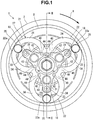
Fig. 1 is a front view of an electromagnetic clutch as an embodiment of the present invention; -
Fig. 2 is a sectional view taken along a line II - II inFig. 1 ; -
Fig. 3 is a front view of a leaf spring; and -
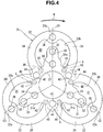
Fig. 4 is a front view of another example of the leaf spring. - An electromagnetic clutch as an embodiment of the present invention will be explained in detail below with reference to
Figs. 1 to 3 . An electromagnetic clutch 1 shown inFig. 1 switches a connected state in which the rotation of arotor 2 depicted on the outermost side inFig. 1 is transmitted to a rotating shaft 3 (seeFig. 2 ) arranged in the axial portion of therotor 2, and a disconnected state in which this power transmission is interrupted. - The
rotor 2 is formed into an annular shape by using a magnetic material, and rotatably supported in afront housing 6 of a car air-conditioner compressor 5 by abearing 4 fitted in the inner circumferential portion of therotor 2. Acylindrical portion 7 projects from one end portion of thefront housing 6. The above-describedbearing 4 is formed on thecylindrical portion 7. In the following explanation, a direction (rightward inFig. 2 ) in which thecylindrical portion 7 projects from thefront housing 6 is frontward of the electromagnetic clutch 1, and a direction opposite to this direction is backward thereof. - A
pulley groove 2a around which a power transmission belt (not shown) is wound is formed in the outer circumferential portion of therotor 2. In this embodiment, therotor 2 forms "a first rotary member" of the present invention, and the rotatingshaft 3 forms "a second rotary member" of the present invention. Afriction surface 2b which comes in contact with afriction surface 8a of an armature 8 (to be described later) is formed on the front end (one end portion in the axial direction) of therotor 2. - Also, an
annular groove 9 which opens backward is formed in therotor 2. Afield 10 is inserted inside thegroove 9. Thefield 10 includes anannular yoke 12 having arecessed groove 11 which opens frontward, and anelectromagnetic coil 14 accommodated in therecessed groove 11 of theyoke 12 and fixed by aninsulating resin 13. Theyoke 12 is fixed to thefront housing 6. - The rotating
shaft 3 is rotatably supported in thefront housing 6, and rotatable with respect to therotor 2. As shown inFig. 2 , the front end portion (one end portion in the axial direction) of the rotatingshaft 3 is accommodated in thecylindrical portion 7 of thefront housing 6. The above-describedrotor 2 is positioned on the same axis as that of the rotatingshaft 3. A relatively thin splinedportion 3a is formed in the front end portion of the rotatingshaft 3. Anarmature hub 15 is fitted on thesplined portion 3a. Thearmature hub 15 includes acylindrical boss 15a which fits on thesplined portion 3a by splining (not shown), and aflange 15b extending outside in the radial direction from the front end portion of theboss 15a. - The
boss 15a is pushed backward by a fixingbolt 16 threadably engaged with the front end portion of therotating shaft 3, and pushed against astep 3b as the rear end portion of thesplined portion 3a via ashim 17. Thearmature hub 15 is fixed to therotating shaft 3 by the fixingbolt 16 by thus threadably engaging the fixingbolt 16 with therotating shaft 3. Theshim 17 is a part for adjusting an air gap G between therotor 2 and thearmature 8. As indicated by the broken lines inFig. 1 , theflange 15b of thearmature 15 is formed into an almost triangular shape when viewed frontways. Aleaf spring 21 is fixed to the three corners of theflange 15b by base-side rivets 18 (to be described later). - The
leaf spring 21 connects thearmature 8 to thearmature hub 15, thereby supporting thearmature 8 by thearmature hub 15. Thearmature 8 is formed by an annular plate made of a magnetic material. Thearmature 8 has a hollow portion. The diameter (the inside dimension of thearmature 8 in the radial direction) of the hollow portion is larger than the outer diameter (the outside dimension of theflange 15b in the radial direction) of theflange 15b of thearmature hub 15. Thearmature 8 is arranged in a position facing the front end of therotor 2 with theflange 15b of thearmature hub 15 being inserted into the hollow portion. - The structure of the
leaf spring 21 will be explained in more detail. As shown inFig. 3 , theleaf spring 21 has three annular connectingpieces 22. The connectingpieces 22 are integrated with anannular base 23 so as to surround it. The three connectingpieces 22 are formed in positions which divide the outer circumferential portion of theannular base 23 into three equal parts in the circumferential direction, and extend outside in the radial direction from the outer circumferential portion of thebase 23. That is, the connectingpieces 22 are formed along three virtual central lines C1 to C3 extending in the radiation direction at the positions which divide the base 23 into three equal parts in the circumferential direction. - Three through
holes 24 are formed in portions intersecting the virtual central lines C1 to C3 in thebase 23. Accordingly, the throughholes 24 are arranged apart from each other in the circumferential direction of thebase 23. The above-described base-side rivets 18 are inserted into the through holes 24. The base-side rivets 18 are inserted into the throughholes 24 and through holes 25 (seeFig. 2 ) formed in theflange 15b of thearmature hub 15 and caulked. That is, the base-side rivets 18 connect theflange 15b of thearmature hub 15 and thebase 23 of theleaf spring 21. Note that ashim 26 shown inFig. 2 can be sandwiched between the base 23 and theflange 15b. Thebase 23 of theleaf spring 21 is positioned on the same axis as that of therotating shaft 3 by being overlaid on and fixed to theflange 15b of thearmature hub 15 by the base-side rivets 18. In this embodiment, the base-side rivet 18 is "a first rivet" of the present invention. - As shown in
Fig. 3 , threestoppers 31 projecting outside in the radiation direction from three portions arranged in the circumferential directions are integrated with thebase portion 23. In this embodiment, the threestoppers 31 project outside in the radiation direction along the virtual central lines C1 to C3 from those portions, in which the throughholes 24 are formed, of the outer circumferential portion of thebase 23. As shown inFigs. 1 and2 , the distal end portions of thestoppers 31 face thearmature 8 in the axial direction of therotating shaft 3. A through hole 32 (seeFig. 3 ) is formed in the distal end portion of thestopper 31, andstopper rubber member 33 is fitted in the throughhole 32. Thestopper rubber member 33 regulates the movement of thearmature 8 in a direction away from therotor 2. - The connecting
piece 22 of theleaf spring 21 is formed by a pair of connectingportions 34 positioned on the two sides of thestopper 31. The pair of connectingportions 34 are formed to be integrated with each other on the two sides of thestopper 31 in the outer circumferential portion of thebase 23, and project outside in the radial direction from thebase 23. Since the distal ends of the pair of connectingportions 34 are connected, the connectingpiece 22 is formed into an annular shape surrounding thestopper 31. The distal ends of the pair of connectingportions 34, i.e., the projecting ends of the connectingportions 34 are equivalent to afree end portion 22a of the connectingpiece 22. As shown inFig. 1 , thefree end portion 22a is fixed to thearmature 8 by a free-end-side rivet 35. - A through
hole 36 is formed in thefree end portion 22a. The free-end-side rivet 35 is inserted into the throughhole 36. As shown inFig. 2 , the free-end-side rivet 35 is caulked as it is inserted into the throughhole 36 formed in the connectingpiece 22 and a throughhole 37 formed in thearmature 8, thereby connecting the connectingpiece 22 andarmature 8. In this embodiment, the free-end-side rivet 35 is "a second rivet" of the present invention. - The three free-end-
side rivets 35 are arranged in positions where the above-described virtual central lines C1 to C3 and threefree end portions 22a intersect each other. Therefore, the base-side rivet 18 for fixing thebase 23 of theleaf spring 21 to thearmature hub 15, the free-end-side rivet 35 for fixing the connectingpiece 22 of theleaf spring 21 to thearmature 8, and thestopper 31 are aligned in the radial direction of thebase 23. - In a state in which the
base 23 is fixed to thearmature hub 15 by the base-side rivets 18, the connectingpieces 22 of theleaf spring 21 bias thearmature 8 away from therotor 2 in the axial direction. Accordingly, in a state in which the magnetism of theelectromagnetic coil 14 does not act on thearmature 8, as shown inFig. 2 , the spring force of theleaf spring 21 presses thearmature 8 against thestopper rubber members 33. The height (the thickness in the axial direction) of thestopper rubber member 33 affects the preset load (the initial reaction of the connecting portions 34) of theleaf spring 21. Thestopper rubber members 33 according to this embodiment set the preset load of theleaf spring 21 at a predetermined value. - The
leaf spring 21 according to this embodiment is punched out of a plate-like leaf spring base material (not shown). By punching out a part of the leaf spring base material, a punchedhole 41 is formed between the connectingpiece 22 and thestopper 31 outside the base 23 in the radial direction. An innercircumferential edge 22b (seeFig. 3 ) of the connectingpiece 22 and anouter edge 31a of thestopper 31 form the hole wall of the punchedhole 41. Of this hole wall, as shown inFig. 1 ,U-shaped recesses 42 extending from the pair of connectingportions 34 of the connectingpiece 22 to thestopper 31 via thebase 23 are formed in positions adjacent, in the rotational direction, to the base-side rivet 18, when viewed in the axial direction. When viewed in the axial direction of therotating shaft 3, the bottoms (deepest portions) of therecesses 42 are formed in positions reaching outer circumferential edges 43 (the three sides of the triangle in this embodiment) of theflange 15b of thearmature hub 15. Therefore, fixed ends of the connectingpiece 22 formed by a cantilever spring, i.e.,boundary portions 44 between the base 23 and the connectingportions 34 of theleaf spring 21 are formed in positions overlapping the outercircumferential edges 43 of theflange 15b, when viewed in the axial direction of therotating shaft 3. - As shown in
Fig. 3 , threenotches 45 are formed in the inner circumferential portion of thebase 23 of theleaf spring 21. Thenotches 45 are formed into a semicircular shape extending outside in the radial direction from the inner circumferential edge of thebase 23, in portions adjacent to and inside the above-describedboundary portions 44 in the radiation direction. When viewed in the axial direction of therotating shaft 3, the bottoms (deepest portions) of thenotches 45 are formed in positions reaching the outercircumferential edges 43 of theflange 15b of thearmature hub 15. - Since the
notches 45 are thus formed in thebase 23, low-strength portions 46 where the base 23 partially narrows are formed in those portions of thebase 23, in which the connectingportions 34 are connected. Referring toFigs. 1 and3 , the low-strength portions 46 are schematically indicated by alternate-long-and-two-short-dashed-line hatched circles. In this embodiment, the low-strength portion 46 is formed in theboundary portion 44 sandwiched between thenotch 45 and the punchedhole 41 described above. The length from the bottom of theU-shaped recess 42 to the bottom of thenotch 45 in the low-strength portion 46 is shorter than the length from the bottom of therecess 42 to the throughhole 24. This makes the strength of the low-strength portion 46 lower than that in the periphery of the throughhole 24. - In a state in which the
stopper rubber members 33 of theleaf spring 21 having the structure as described above are in contact with that surface of thearmature 8, which is opposite to therotor 2, thebase 23 is fixed to thearmature hub 15 by the base-side rivets 18, and the connectingpieces 22 are fixed to thearmature 8 by the free-end-side rivets 35. - When electric power is supplied to the
electromagnetic coil 14 in the electromagnetic clutch 1, as indicated by the alternate long and two short dashed line inFig. 2 , a magnetic flux Φ passes through therotor 2 andarmature 8, and thearmature 8 is magnetically attracted by therotor 2 against the spring force of theleaf spring 21. When thearmature 8 is attracted by therotor 2, thefriction surface 8a of thearmature 8 frictionally engages with thefriction surface 2b of therotating rotor 2, and the rotational force is transmitted from the connectingpieces 22 to thebase 23 of theleaf spring 21. In this state, the connectingpieces 22 are strained. Note that the connectingpieces 22 are also strained when connected to thearmature 8 by the free-end-side rivets 35. In this embodiment, thenotches 45 are formed near theboundary portions 44 between the base 23 and the connectingportions 34, and the low-strength portions 46 deform and disperse the force. This decreases stress caused in the rivet caulked portions (around the through holes 24) of the base 23 by the strain of the connectingpieces 22. - In the connected state in which the
armature 8 is attracted to therotor 2, the rotation of therotor 2 is transmitted to therotating shaft 3 via theleaf spring 21 andarmature hub 15. If therotating shaft 3 on the driven side is locked by some cause in this connected state, an excess load is applied to theleaf spring 21. In this case, if, for example, therotor 2 is rotating clockwise inFig. 1 as indicated by an arrow R inFig. 1 , the pair of connectingportions 34 forming the connectingpiece 22 are displaced to the downstream side in the rotational direction with respect to thestopper 31. Of the pair of connectingportions 34, one connectingportion 34 positioned downstream in the rotational direction elastically deforms in a direction in which the above-describedU-shaped recess 42 expands. The other connectingportion 34 elastically deforms in a direction in which theU-shaped recess 42 narrows. In this state, the stress becomes maximum in the connecting portion between therecess 42 and the connectingportion 34 positioned downstream in the rotational direction, particularly, in a region S shown inFig. 3 . - If the deformation amount of the connecting
portion 34 exceeds the limit, the stress concentrates from the region S of theleaf spring 21 to the low-strength portion 46 and cracks it, so the base 23 is broken in the low-strength portion 46. Since thebase 23 is broken in the low-strength portions 46, theleaf spring 21 is divided into a plurality of parts. That is, theleaf spring 21 is divided into a part of the base 23 fixed to thearmature hub 15, and the connectingportion 34 and a part of the base 23 fixed to thearmature 8. - The
stopper 31 is connected to the part of the base 23 fixed to thearmature hub 15. Even when theleaf spring 21 is broken, therefore, thestopper 31 remains on the side of thearmature hub 15. When power supply to the electromagnetic clutch 1 is stopped in this state in which theleaf spring 21 is broken, thearmature 8 leaves therotor 2 and abuts against thestopper rubber member 33. As a consequence, thestopper rubber member 33 prevents thearmature 8 from falling outside the electromagnetic clutch 1. In this embodiment, therefore, even when an excess load is applied to theleaf spring 21 and theleaf spring 21 is broken, thearmature 8 does not fall outside the electromagnetic clutch 1. - In this embodiment, the low-
strength portion 46 is formed in that portion of thebase 23, which is adjacent to thenotch 45 of theleaf spring 21, and near theboundary portion 44 between the base 23 and the connectingportion 34. Accordingly, the low-strength portion 46 of the base 23 easily deforms when an external force (a strain or rotational force) is applied from the connectingportion 34 to thebase 23, and this reduces stress occurring in the rivet caulking portion of thebase 23. Since, therefore, thebase 23 is hardly broken in the rivet caulking portion of thebase 23, thestopper 31 easily remains, and this makes it possible to further reliably prevent thearmature 8 from falling outside the electromagnetic clutch 1. - In the
leaf spring 21 according to this embodiment, the pair of connectingportions 34 positioned on the two sides of thestopper 31 form the annular connectingpiece 22 surrounding thestopper 31. The base-side rivet 18 for fixing thebase 23 of theleaf spring 21 to thearmature hub 15, the free-end-side rivet 35 for fixing the connectingpiece 22 to thearmature 8, and thestopper 31 are aligned in the radiation direction of thebase 23. Therefore, the connectingpiece 22 can be formed to be axially symmetrical with respect to a corresponding one of the above-described virtual central lines C1 to C3. Consequently, the electromagnetic clutch 1 which is not restricted in rotational direction can be provided. - In this embodiment, the low-
strength portions 45 are formed by forming thesemicircular notches 45 in the inner circumferential portion of thebase 23. However, the shape of thenotch 45 is not limited to a semicircular shape, and can appropriately be changed. Also, the low-strength portion 46 can be formed by only reducing the area of that portion of thebase 23, which connects adjacent connectingpieces 22. As shown inFig. 4 , therefore, the low-strength portion 46 can also be formed by forming a throughhole 47 in that portion of thebase 23, which connects adjacent connectingpieces 22. - In addition, the
flange 15b of thearmature hub 15 has an almost triangular shape, but may also have rounded corners as shown inFig. 1 . Furthermore, the outercircumferential edge 43 of theflange 15b need not be straight, and may also be an arc having a curvature different from that of the arc of the corner. - The example in which the three connecting
pieces 22, threestoppers 31, threenotches 45, three base-side rivets 18, and three free-end-side rivets 35 are formed has been explained above. However, the number of these elements need only be two or more. More specifically, in a car air-conditioner electromagnetic clutch like this embodiment, three or four connectingpieces 22 and the like are formed. Also, in an electromagnetic clutch for general industries, five connectingpieces 22 and the like are formed in some cases.
Claims (3)
- An electromagnetic clutch comprising:a first rotary member (2) formed of a magnetic material;a second rotary member (3) arranged in an axial portion of the first rotary member (2), and rotatable with respect to the first rotary member (2);an armature hub (15) including a boss (15a) formed on one end portion of the second rotary member (3) in an axial direction, and a flange (15b) extending outside in a radial direction from the boss (15a);an armature (8) formed into an annular shape including a hollow portion having a diameter larger than an outer diameter of the flange (15b), and arranged in a position facing one end portion of the first rotary member (2) in the axial direction, the flange (15b) being inserted into the hollow portion;a single leaf spring (21) configured to connect the armature (8) to the flange (15b), and bias the armature (8) away from the first rotary member (2) by a spring force;an electromagnetic coil (14) configured to generate a magnetic flux (Φ), and magnetically attract the armature (8) to the first rotary member (2) against the spring force of the leaf spring (21);a plurality of first rivets (18) configured to fix the leaf spring (21) to the flange (15b); anda plurality of second rivets (35) configured to fix the leaf spring (21) to the armature (8),wherein the leaf spring (21) includesa base (23) formed into an annular shape, positioned on the same axis as that of the second rotary member (3), and overlaid on and fixed to the flange (15b),a plurality of first through holes (24) which are formed in the base (23), and into which the plurality of first rivets (18) are inserted, respectively,a plurality of stoppers (31) projecting outside in the radial direction from portions, in which the first plurality of through holes (24) are formed, of an outer circumferential portion of the base (23) and facing the armature (8) in the axial direction,a plurality of connecting pieces (22) each including a pair of connecting portions (34) projecting outside in the radial direction from two sides of each of the plurality of stoppers (31) on an outer circumferential portion of the base (23), and having distal ends connected to each other,a plurality of second through holes (36) which are formed in projecting ends of the plurality of connecting pieces (22), respectively, and into which the plurality of second rivets (35) are inserted, resceptively,a plurality of punched holes (41) formed between the plurality of connecting pieces (22) and the plurality of stoppers (31), respectively, outside the base (23) in the radial direction,characterized by
a plurality of low-strength portions (46) formed in boundary portions (44) between the base (23) and the plurality of connecting portions (34) and each having strength lower than that in a periphery of each of the plurality of first through holes (24), the boundary portions (44) overlapping an outer circumferential edge (43) of the flange (15b) when viewed in an axial direction of the second rotary member (3),
wherein
the leaf spring (21) further includes a plurality of notches (45) each formed in a portion adjacent to and inside each of the boundary portions (44) in the radial direction, and each extending outside in the radial direction from an inner circumferential edge of the base (23), and
the plurality of low-strength portions (46) are sandwiched between the plurality of notches (45) and the plurality of punched holes (41). - The clutch according to claim 1, wherein
each of the punched holes (41) includes U-shaped recesses (42) extending from the pair of connecting portions (34) to each of the plurality of stoppers (31) via the base (23), when viewed in the axial direction of the second rotary member (3), and
bottoms of the U-shaped recesses (42) reach the outer circumferential edge (43) of the flange (15b), when viewed in the axial direction of the second rotary member (3). - The clutch according to claim 1, wherein
each of the plurality of notches (45) is formed into a semicircular shape extending outside in the radial direction from an inner circumferential edge of the base (23), and
a bottom of each of the plurality of notches (45) reaches the outer circumferential edge (43) of the flange (15b), when viewed in the axial direction of the second rotary member (3).
Applications Claiming Priority (2)
| Application Number | Priority Date | Filing Date | Title |
|---|---|---|---|
| JP2015177261 | 2015-09-09 | ||
| JP2016167676A JP6684187B2 (en) | 2015-09-09 | 2016-08-30 | Electromagnetic clutch |
Publications (3)
| Publication Number | Publication Date |
|---|---|
| EP3141772A2 EP3141772A2 (en) | 2017-03-15 |
| EP3141772A3 EP3141772A3 (en) | 2017-03-29 |
| EP3141772B1 true EP3141772B1 (en) | 2018-05-02 |
Family
ID=56883659
Family Applications (1)
| Application Number | Title | Priority Date | Filing Date |
|---|---|---|---|
| EP16187456.5A Active EP3141772B1 (en) | 2015-09-09 | 2016-09-06 | Electromagnetic clutch |
Country Status (2)
| Country | Link |
|---|---|
| US (1) | US10036431B2 (en) |
| EP (1) | EP3141772B1 (en) |
Families Citing this family (4)
| Publication number | Priority date | Publication date | Assignee | Title |
|---|---|---|---|---|
| WO2016115161A1 (en) * | 2015-01-12 | 2016-07-21 | Decandia Douglas H | Mechanical energy transfer system |
| KR102436354B1 (en) * | 2017-02-27 | 2022-08-25 | 한온시스템 주식회사 | Clutch and compressor having the same |
| KR102590950B1 (en) * | 2017-06-28 | 2023-10-19 | 한온시스템 주식회사 | Clutch and compressor having the same |
| US10989258B1 (en) | 2019-10-25 | 2021-04-27 | The Hilliard Corporation | Flexible armature plate for an electro-magnetic overrunning clutch |
Family Cites Families (14)
| Publication number | Priority date | Publication date | Assignee | Title |
|---|---|---|---|---|
| JPS6137862Y2 (en) | 1980-08-22 | 1986-11-01 | ||
| JPS6137862U (en) | 1984-08-13 | 1986-03-08 | サンセイアルミ株式会社 | Assembly structure of box-shaped case |
| US4704554A (en) * | 1985-04-15 | 1987-11-03 | Mita Industrial Co., Ltd. | Clutch mechanisms with improved electromagnetic means, spring supports and assembly versatility |
| JP2932217B2 (en) * | 1991-03-20 | 1999-08-09 | 小倉クラッチ株式会社 | Electromagnetic clutch |
| US5791039A (en) * | 1993-03-18 | 1998-08-11 | Nippondenso Co., Ltd. | Method for manufacturing a rotor of a magnetic clutch |
| US5762173A (en) * | 1995-04-25 | 1998-06-09 | Mita Industrial Co., Ltd. | Electromagnetic clutch |
| JP3627339B2 (en) * | 1996-01-18 | 2005-03-09 | 株式会社デンソー | Electromagnetic clutch |
| JP3627202B2 (en) | 1996-08-09 | 2005-03-09 | 株式会社鷺宮製作所 | High durability solenoid valve |
| JPH1054426A (en) * | 1996-08-09 | 1998-02-24 | Zexel Corp | Electromagnetic clutch |
| JPH10115332A (en) * | 1996-10-11 | 1998-05-06 | Zexel Corp | Electromagnetic clutch |
| JPH10115333A (en) * | 1996-10-11 | 1998-05-06 | Zexel Corp | Electromagnetic clutch |
| EP0836076B1 (en) | 1996-10-11 | 2002-05-22 | Brown & Sharpe Tesa S.A. | Capacitive dimension measuring device |
| JP2004052985A (en) * | 2002-07-24 | 2004-02-19 | Zexel Valeo Climate Control Corp | Electromagnetic clutch |
| JP4985749B2 (en) * | 2009-11-30 | 2012-07-25 | 株式会社デンソー | Clutch mechanism |
-
2016
- 2016-09-06 EP EP16187456.5A patent/EP3141772B1/en active Active
- 2016-09-08 US US15/260,063 patent/US10036431B2/en active Active
Non-Patent Citations (1)
| Title |
|---|
| None * |
Also Published As
| Publication number | Publication date |
|---|---|
| US10036431B2 (en) | 2018-07-31 |
| US20170067516A1 (en) | 2017-03-09 |
| EP3141772A2 (en) | 2017-03-15 |
| EP3141772A3 (en) | 2017-03-29 |
Similar Documents
| Publication | Publication Date | Title |
|---|---|---|
| EP3141772B1 (en) | Electromagnetic clutch | |
| JP6684187B2 (en) | Electromagnetic clutch | |
| US20120111690A1 (en) | Electromagnetic clutch | |
| US20060219514A1 (en) | Electromagnetic clutch | |
| US6823974B2 (en) | Electromagnetic clutch | |
| EP3369968B1 (en) | Differential apparatus | |
| JPH08326781A (en) | Electromagnetic connection device | |
| JP4971900B2 (en) | Electromagnetic clutch | |
| EP3073143B1 (en) | Electromagnetic clutch | |
| US8973727B1 (en) | Electromagnetic clutch | |
| JP2013234723A (en) | Electromagnetic clutch | |
| US20060219512A1 (en) | Electromagnetic clutch | |
| JPH0972354A (en) | Electromagnetic connecting device | |
| JP5509052B2 (en) | Electromagnetic clutch | |
| JP4541178B2 (en) | Rotation transmission device | |
| JP5498922B2 (en) | Electromagnetic coupling device | |
| JP2006233847A (en) | Electromagnetic clutch of compressor | |
| CN115681367A (en) | Electromagnetic brake device for motor | |
| KR101901686B1 (en) | disc and hub assembly of electromagnetic clutch for compressor | |
| JP2011163515A (en) | Electromagnetic coupling device | |
| JP3587707B2 (en) | Electromagnetic coupling device | |
| JP2005155841A (en) | Power transmitting device | |
| JPH03107621A (en) | Magnetic connecting device | |
| JPH08200400A (en) | Electromagnetic connecting device | |
| JP2001153155A (en) | Electromagnetic coupling device |
Legal Events
| Date | Code | Title | Description |
|---|---|---|---|
| PUAI | Public reference made under article 153(3) epc to a published international application that has entered the european phase |
Free format text: ORIGINAL CODE: 0009012 |
|
| STAA | Information on the status of an ep patent application or granted ep patent |
Free format text: STATUS: THE APPLICATION HAS BEEN PUBLISHED |
|
| PUAL | Search report despatched |
Free format text: ORIGINAL CODE: 0009013 |
|
| AK | Designated contracting states |
Kind code of ref document: A2 Designated state(s): AL AT BE BG CH CY CZ DE DK EE ES FI FR GB GR HR HU IE IS IT LI LT LU LV MC MK MT NL NO PL PT RO RS SE SI SK SM TR |
|
| AX | Request for extension of the european patent |
Extension state: BA ME |
|
| AK | Designated contracting states |
Kind code of ref document: A3 Designated state(s): AL AT BE BG CH CY CZ DE DK EE ES FI FR GB GR HR HU IE IS IT LI LT LU LV MC MK MT NL NO PL PT RO RS SE SI SK SM TR |
|
| AX | Request for extension of the european patent |
Extension state: BA ME |
|
| RIC1 | Information provided on ipc code assigned before grant |
Ipc: F16D 27/00 20060101ALI20170220BHEP Ipc: F16D 27/112 20060101AFI20170220BHEP |
|
| STAA | Information on the status of an ep patent application or granted ep patent |
Free format text: STATUS: REQUEST FOR EXAMINATION WAS MADE |
|
| 17P | Request for examination filed |
Effective date: 20170929 |
|
| RBV | Designated contracting states (corrected) |
Designated state(s): AL AT BE BG CH CY CZ DE DK EE ES FI FR GB GR HR HU IE IS IT LI LT LU LV MC MK MT NL NO PL PT RO RS SE SI SK SM TR |
|
| GRAP | Despatch of communication of intention to grant a patent |
Free format text: ORIGINAL CODE: EPIDOSNIGR1 |
|
| STAA | Information on the status of an ep patent application or granted ep patent |
Free format text: STATUS: GRANT OF PATENT IS INTENDED |
|
| INTG | Intention to grant announced |
Effective date: 20171201 |
|
| GRAS | Grant fee paid |
Free format text: ORIGINAL CODE: EPIDOSNIGR3 |
|
| GRAA | (expected) grant |
Free format text: ORIGINAL CODE: 0009210 |
|
| STAA | Information on the status of an ep patent application or granted ep patent |
Free format text: STATUS: THE PATENT HAS BEEN GRANTED |
|
| AK | Designated contracting states |
Kind code of ref document: B1 Designated state(s): AL AT BE BG CH CY CZ DE DK EE ES FI FR GB GR HR HU IE IS IT LI LT LU LV MC MK MT NL NO PL PT RO RS SE SI SK SM TR |
|
| REG | Reference to a national code |
Ref country code: GB Ref legal event code: FG4D |
|
| REG | Reference to a national code |
Ref country code: CH Ref legal event code: EP Ref country code: AT Ref legal event code: REF Ref document number: 995595 Country of ref document: AT Kind code of ref document: T Effective date: 20180515 |
|
| REG | Reference to a national code |
Ref country code: DE Ref legal event code: R096 Ref document number: 602016002745 Country of ref document: DE Ref country code: IE Ref legal event code: FG4D |
|
| REG | Reference to a national code |
Ref country code: NL Ref legal event code: MP Effective date: 20180502 |
|
| REG | Reference to a national code |
Ref country code: LT Ref legal event code: MG4D |
|
| REG | Reference to a national code |
Ref country code: FR Ref legal event code: PLFP Year of fee payment: 3 |
|
| PG25 | Lapsed in a contracting state [announced via postgrant information from national office to epo] |
Ref country code: BG Free format text: LAPSE BECAUSE OF FAILURE TO SUBMIT A TRANSLATION OF THE DESCRIPTION OR TO PAY THE FEE WITHIN THE PRESCRIBED TIME-LIMIT Effective date: 20180802 Ref country code: NO Free format text: LAPSE BECAUSE OF FAILURE TO SUBMIT A TRANSLATION OF THE DESCRIPTION OR TO PAY THE FEE WITHIN THE PRESCRIBED TIME-LIMIT Effective date: 20180802 Ref country code: FI Free format text: LAPSE BECAUSE OF FAILURE TO SUBMIT A TRANSLATION OF THE DESCRIPTION OR TO PAY THE FEE WITHIN THE PRESCRIBED TIME-LIMIT Effective date: 20180502 Ref country code: SE Free format text: LAPSE BECAUSE OF FAILURE TO SUBMIT A TRANSLATION OF THE DESCRIPTION OR TO PAY THE FEE WITHIN THE PRESCRIBED TIME-LIMIT Effective date: 20180502 Ref country code: LT Free format text: LAPSE BECAUSE OF FAILURE TO SUBMIT A TRANSLATION OF THE DESCRIPTION OR TO PAY THE FEE WITHIN THE PRESCRIBED TIME-LIMIT Effective date: 20180502 Ref country code: ES Free format text: LAPSE BECAUSE OF FAILURE TO SUBMIT A TRANSLATION OF THE DESCRIPTION OR TO PAY THE FEE WITHIN THE PRESCRIBED TIME-LIMIT Effective date: 20180502 |
|
| PG25 | Lapsed in a contracting state [announced via postgrant information from national office to epo] |
Ref country code: LV Free format text: LAPSE BECAUSE OF FAILURE TO SUBMIT A TRANSLATION OF THE DESCRIPTION OR TO PAY THE FEE WITHIN THE PRESCRIBED TIME-LIMIT Effective date: 20180502 Ref country code: NL Free format text: LAPSE BECAUSE OF FAILURE TO SUBMIT A TRANSLATION OF THE DESCRIPTION OR TO PAY THE FEE WITHIN THE PRESCRIBED TIME-LIMIT Effective date: 20180502 Ref country code: HR Free format text: LAPSE BECAUSE OF FAILURE TO SUBMIT A TRANSLATION OF THE DESCRIPTION OR TO PAY THE FEE WITHIN THE PRESCRIBED TIME-LIMIT Effective date: 20180502 Ref country code: GR Free format text: LAPSE BECAUSE OF FAILURE TO SUBMIT A TRANSLATION OF THE DESCRIPTION OR TO PAY THE FEE WITHIN THE PRESCRIBED TIME-LIMIT Effective date: 20180803 Ref country code: RS Free format text: LAPSE BECAUSE OF FAILURE TO SUBMIT A TRANSLATION OF THE DESCRIPTION OR TO PAY THE FEE WITHIN THE PRESCRIBED TIME-LIMIT Effective date: 20180502 |
|
| REG | Reference to a national code |
Ref country code: AT Ref legal event code: MK05 Ref document number: 995595 Country of ref document: AT Kind code of ref document: T Effective date: 20180502 |
|
| PG25 | Lapsed in a contracting state [announced via postgrant information from national office to epo] |
Ref country code: PL Free format text: LAPSE BECAUSE OF FAILURE TO SUBMIT A TRANSLATION OF THE DESCRIPTION OR TO PAY THE FEE WITHIN THE PRESCRIBED TIME-LIMIT Effective date: 20180502 Ref country code: EE Free format text: LAPSE BECAUSE OF FAILURE TO SUBMIT A TRANSLATION OF THE DESCRIPTION OR TO PAY THE FEE WITHIN THE PRESCRIBED TIME-LIMIT Effective date: 20180502 Ref country code: DK Free format text: LAPSE BECAUSE OF FAILURE TO SUBMIT A TRANSLATION OF THE DESCRIPTION OR TO PAY THE FEE WITHIN THE PRESCRIBED TIME-LIMIT Effective date: 20180502 Ref country code: RO Free format text: LAPSE BECAUSE OF FAILURE TO SUBMIT A TRANSLATION OF THE DESCRIPTION OR TO PAY THE FEE WITHIN THE PRESCRIBED TIME-LIMIT Effective date: 20180502 Ref country code: AT Free format text: LAPSE BECAUSE OF FAILURE TO SUBMIT A TRANSLATION OF THE DESCRIPTION OR TO PAY THE FEE WITHIN THE PRESCRIBED TIME-LIMIT Effective date: 20180502 Ref country code: CZ Free format text: LAPSE BECAUSE OF FAILURE TO SUBMIT A TRANSLATION OF THE DESCRIPTION OR TO PAY THE FEE WITHIN THE PRESCRIBED TIME-LIMIT Effective date: 20180502 Ref country code: SK Free format text: LAPSE BECAUSE OF FAILURE TO SUBMIT A TRANSLATION OF THE DESCRIPTION OR TO PAY THE FEE WITHIN THE PRESCRIBED TIME-LIMIT Effective date: 20180502 |
|
| REG | Reference to a national code |
Ref country code: DE Ref legal event code: R097 Ref document number: 602016002745 Country of ref document: DE |
|
| PG25 | Lapsed in a contracting state [announced via postgrant information from national office to epo] |
Ref country code: SM Free format text: LAPSE BECAUSE OF FAILURE TO SUBMIT A TRANSLATION OF THE DESCRIPTION OR TO PAY THE FEE WITHIN THE PRESCRIBED TIME-LIMIT Effective date: 20180502 Ref country code: IT Free format text: LAPSE BECAUSE OF FAILURE TO SUBMIT A TRANSLATION OF THE DESCRIPTION OR TO PAY THE FEE WITHIN THE PRESCRIBED TIME-LIMIT Effective date: 20180502 |
|
| PLBE | No opposition filed within time limit |
Free format text: ORIGINAL CODE: 0009261 |
|
| STAA | Information on the status of an ep patent application or granted ep patent |
Free format text: STATUS: NO OPPOSITION FILED WITHIN TIME LIMIT |
|
| 26N | No opposition filed |
Effective date: 20190205 |
|
| PG25 | Lapsed in a contracting state [announced via postgrant information from national office to epo] |
Ref country code: MC Free format text: LAPSE BECAUSE OF FAILURE TO SUBMIT A TRANSLATION OF THE DESCRIPTION OR TO PAY THE FEE WITHIN THE PRESCRIBED TIME-LIMIT Effective date: 20180502 |
|
| PG25 | Lapsed in a contracting state [announced via postgrant information from national office to epo] |
Ref country code: SI Free format text: LAPSE BECAUSE OF FAILURE TO SUBMIT A TRANSLATION OF THE DESCRIPTION OR TO PAY THE FEE WITHIN THE PRESCRIBED TIME-LIMIT Effective date: 20180502 |
|
| REG | Reference to a national code |
Ref country code: BE Ref legal event code: MM Effective date: 20180930 |
|
| REG | Reference to a national code |
Ref country code: IE Ref legal event code: MM4A |
|
| PG25 | Lapsed in a contracting state [announced via postgrant information from national office to epo] |
Ref country code: LU Free format text: LAPSE BECAUSE OF NON-PAYMENT OF DUE FEES Effective date: 20180906 |
|
| PG25 | Lapsed in a contracting state [announced via postgrant information from national office to epo] |
Ref country code: IE Free format text: LAPSE BECAUSE OF NON-PAYMENT OF DUE FEES Effective date: 20180906 |
|
| PG25 | Lapsed in a contracting state [announced via postgrant information from national office to epo] |
Ref country code: BE Free format text: LAPSE BECAUSE OF NON-PAYMENT OF DUE FEES Effective date: 20180930 |
|
| PG25 | Lapsed in a contracting state [announced via postgrant information from national office to epo] |
Ref country code: AL Free format text: LAPSE BECAUSE OF FAILURE TO SUBMIT A TRANSLATION OF THE DESCRIPTION OR TO PAY THE FEE WITHIN THE PRESCRIBED TIME-LIMIT Effective date: 20180502 |
|
| PG25 | Lapsed in a contracting state [announced via postgrant information from national office to epo] |
Ref country code: MT Free format text: LAPSE BECAUSE OF NON-PAYMENT OF DUE FEES Effective date: 20180906 |
|
| PG25 | Lapsed in a contracting state [announced via postgrant information from national office to epo] |
Ref country code: TR Free format text: LAPSE BECAUSE OF FAILURE TO SUBMIT A TRANSLATION OF THE DESCRIPTION OR TO PAY THE FEE WITHIN THE PRESCRIBED TIME-LIMIT Effective date: 20180502 |
|
| PG25 | Lapsed in a contracting state [announced via postgrant information from national office to epo] |
Ref country code: PT Free format text: LAPSE BECAUSE OF FAILURE TO SUBMIT A TRANSLATION OF THE DESCRIPTION OR TO PAY THE FEE WITHIN THE PRESCRIBED TIME-LIMIT Effective date: 20180502 |
|
| REG | Reference to a national code |
Ref country code: CH Ref legal event code: PL |
|
| PG25 | Lapsed in a contracting state [announced via postgrant information from national office to epo] |
Ref country code: HU Free format text: LAPSE BECAUSE OF FAILURE TO SUBMIT A TRANSLATION OF THE DESCRIPTION OR TO PAY THE FEE WITHIN THE PRESCRIBED TIME-LIMIT; INVALID AB INITIO Effective date: 20160906 Ref country code: CY Free format text: LAPSE BECAUSE OF FAILURE TO SUBMIT A TRANSLATION OF THE DESCRIPTION OR TO PAY THE FEE WITHIN THE PRESCRIBED TIME-LIMIT Effective date: 20180502 Ref country code: MK Free format text: LAPSE BECAUSE OF NON-PAYMENT OF DUE FEES Effective date: 20180502 |
|
| PG25 | Lapsed in a contracting state [announced via postgrant information from national office to epo] |
Ref country code: LI Free format text: LAPSE BECAUSE OF NON-PAYMENT OF DUE FEES Effective date: 20190930 Ref country code: CH Free format text: LAPSE BECAUSE OF NON-PAYMENT OF DUE FEES Effective date: 20190930 Ref country code: IS Free format text: LAPSE BECAUSE OF FAILURE TO SUBMIT A TRANSLATION OF THE DESCRIPTION OR TO PAY THE FEE WITHIN THE PRESCRIBED TIME-LIMIT Effective date: 20180902 |
|
| GBPC | Gb: european patent ceased through non-payment of renewal fee |
Effective date: 20200906 |
|
| PG25 | Lapsed in a contracting state [announced via postgrant information from national office to epo] |
Ref country code: GB Free format text: LAPSE BECAUSE OF NON-PAYMENT OF DUE FEES Effective date: 20200906 |
|
| PGFP | Annual fee paid to national office [announced via postgrant information from national office to epo] |
Ref country code: FR Payment date: 20230802 Year of fee payment: 8 Ref country code: DE Payment date: 20230930 Year of fee payment: 8 |