EP3072769A2 - Verfahren zur suchraumeinschränkung eines modellbasierten online-optimierungsverfahrens zur prädiktion einer zustandsgrösse eines fahrzeugs - Google Patents
Verfahren zur suchraumeinschränkung eines modellbasierten online-optimierungsverfahrens zur prädiktion einer zustandsgrösse eines fahrzeugs Download PDFInfo
- Publication number
- EP3072769A2 EP3072769A2 EP16000224.2A EP16000224A EP3072769A2 EP 3072769 A2 EP3072769 A2 EP 3072769A2 EP 16000224 A EP16000224 A EP 16000224A EP 3072769 A2 EP3072769 A2 EP 3072769A2
- Authority
- EP
- European Patent Office
- Prior art keywords
- state variable
- search space
- state
- course
- predicted
- Prior art date
- Legal status (The legal status is an assumption and is not a legal conclusion. Google has not performed a legal analysis and makes no representation as to the accuracy of the status listed.)
- Granted
Links
Images

Classifications
-
- B—PERFORMING OPERATIONS; TRANSPORTING
- B60—VEHICLES IN GENERAL
- B60W—CONJOINT CONTROL OF VEHICLE SUB-UNITS OF DIFFERENT TYPE OR DIFFERENT FUNCTION; CONTROL SYSTEMS SPECIALLY ADAPTED FOR HYBRID VEHICLES; ROAD VEHICLE DRIVE CONTROL SYSTEMS FOR PURPOSES NOT RELATED TO THE CONTROL OF A PARTICULAR SUB-UNIT
- B60W10/00—Conjoint control of vehicle sub-units of different type or different function
- B60W10/24—Conjoint control of vehicle sub-units of different type or different function including control of energy storage means
- B60W10/26—Conjoint control of vehicle sub-units of different type or different function including control of energy storage means for electrical energy, e.g. batteries or capacitors
-
- B—PERFORMING OPERATIONS; TRANSPORTING
- B60—VEHICLES IN GENERAL
- B60W—CONJOINT CONTROL OF VEHICLE SUB-UNITS OF DIFFERENT TYPE OR DIFFERENT FUNCTION; CONTROL SYSTEMS SPECIALLY ADAPTED FOR HYBRID VEHICLES; ROAD VEHICLE DRIVE CONTROL SYSTEMS FOR PURPOSES NOT RELATED TO THE CONTROL OF A PARTICULAR SUB-UNIT
- B60W20/00—Control systems specially adapted for hybrid vehicles
- B60W20/10—Controlling the power contribution of each of the prime movers to meet required power demand
- B60W20/11—Controlling the power contribution of each of the prime movers to meet required power demand using model predictive control [MPC] strategies, i.e. control methods based on models predicting performance
-
- B—PERFORMING OPERATIONS; TRANSPORTING
- B60—VEHICLES IN GENERAL
- B60W—CONJOINT CONTROL OF VEHICLE SUB-UNITS OF DIFFERENT TYPE OR DIFFERENT FUNCTION; CONTROL SYSTEMS SPECIALLY ADAPTED FOR HYBRID VEHICLES; ROAD VEHICLE DRIVE CONTROL SYSTEMS FOR PURPOSES NOT RELATED TO THE CONTROL OF A PARTICULAR SUB-UNIT
- B60W20/00—Control systems specially adapted for hybrid vehicles
- B60W20/10—Controlling the power contribution of each of the prime movers to meet required power demand
- B60W20/12—Controlling the power contribution of each of the prime movers to meet required power demand using control strategies taking into account route information
-
- B—PERFORMING OPERATIONS; TRANSPORTING
- B60—VEHICLES IN GENERAL
- B60W—CONJOINT CONTROL OF VEHICLE SUB-UNITS OF DIFFERENT TYPE OR DIFFERENT FUNCTION; CONTROL SYSTEMS SPECIALLY ADAPTED FOR HYBRID VEHICLES; ROAD VEHICLE DRIVE CONTROL SYSTEMS FOR PURPOSES NOT RELATED TO THE CONTROL OF A PARTICULAR SUB-UNIT
- B60W50/00—Details of control systems for road vehicle drive control not related to the control of a particular sub-unit, e.g. process diagnostic or vehicle driver interfaces
- B60W50/0097—Predicting future conditions
-
- G—PHYSICS
- G05—CONTROLLING; REGULATING
- G05B—CONTROL OR REGULATING SYSTEMS IN GENERAL; FUNCTIONAL ELEMENTS OF SUCH SYSTEMS; MONITORING OR TESTING ARRANGEMENTS FOR SUCH SYSTEMS OR ELEMENTS
- G05B13/00—Adaptive control systems, i.e. systems automatically adjusting themselves to have a performance which is optimum according to some preassigned criterion
- G05B13/02—Adaptive control systems, i.e. systems automatically adjusting themselves to have a performance which is optimum according to some preassigned criterion electric
- G05B13/04—Adaptive control systems, i.e. systems automatically adjusting themselves to have a performance which is optimum according to some preassigned criterion electric involving the use of models or simulators
- G05B13/048—Adaptive control systems, i.e. systems automatically adjusting themselves to have a performance which is optimum according to some preassigned criterion electric involving the use of models or simulators using a predictor
-
- B—PERFORMING OPERATIONS; TRANSPORTING
- B60—VEHICLES IN GENERAL
- B60W—CONJOINT CONTROL OF VEHICLE SUB-UNITS OF DIFFERENT TYPE OR DIFFERENT FUNCTION; CONTROL SYSTEMS SPECIALLY ADAPTED FOR HYBRID VEHICLES; ROAD VEHICLE DRIVE CONTROL SYSTEMS FOR PURPOSES NOT RELATED TO THE CONTROL OF A PARTICULAR SUB-UNIT
- B60W50/00—Details of control systems for road vehicle drive control not related to the control of a particular sub-unit, e.g. process diagnostic or vehicle driver interfaces
- B60W2050/0001—Details of the control system
- B60W2050/0002—Automatic control, details of type of controller or control system architecture
- B60W2050/0013—Optimal controllers
-
- B—PERFORMING OPERATIONS; TRANSPORTING
- B60—VEHICLES IN GENERAL
- B60W—CONJOINT CONTROL OF VEHICLE SUB-UNITS OF DIFFERENT TYPE OR DIFFERENT FUNCTION; CONTROL SYSTEMS SPECIALLY ADAPTED FOR HYBRID VEHICLES; ROAD VEHICLE DRIVE CONTROL SYSTEMS FOR PURPOSES NOT RELATED TO THE CONTROL OF A PARTICULAR SUB-UNIT
- B60W2552/00—Input parameters relating to infrastructure
- B60W2552/15—Road slope, i.e. the inclination of a road segment in the longitudinal direction
-
- B—PERFORMING OPERATIONS; TRANSPORTING
- B60—VEHICLES IN GENERAL
- B60W—CONJOINT CONTROL OF VEHICLE SUB-UNITS OF DIFFERENT TYPE OR DIFFERENT FUNCTION; CONTROL SYSTEMS SPECIALLY ADAPTED FOR HYBRID VEHICLES; ROAD VEHICLE DRIVE CONTROL SYSTEMS FOR PURPOSES NOT RELATED TO THE CONTROL OF A PARTICULAR SUB-UNIT
- B60W2552/00—Input parameters relating to infrastructure
- B60W2552/20—Road profile, i.e. the change in elevation or curvature of a plurality of continuous road segments
-
- B—PERFORMING OPERATIONS; TRANSPORTING
- B60—VEHICLES IN GENERAL
- B60W—CONJOINT CONTROL OF VEHICLE SUB-UNITS OF DIFFERENT TYPE OR DIFFERENT FUNCTION; CONTROL SYSTEMS SPECIALLY ADAPTED FOR HYBRID VEHICLES; ROAD VEHICLE DRIVE CONTROL SYSTEMS FOR PURPOSES NOT RELATED TO THE CONTROL OF A PARTICULAR SUB-UNIT
- B60W2556/00—Input parameters relating to data
- B60W2556/45—External transmission of data to or from the vehicle
- B60W2556/50—External transmission of data to or from the vehicle of positioning data, e.g. GPS [Global Positioning System] data
Definitions
- the invention relates to a method for the search space restriction of a model-based online optimization method for the prediction of a state variable of a vehicle.
- the method relates to a method for restricting a search space for a model-based online optimization method, which determines a predicted optimal course of a state variable of a vehicle within a predefined search space for a prediction horizon.
- assistance systems have been increasingly used in vehicles to increase safety, efficiency and comfort in particular. From practice it is known that especially in vehicles that allow a high degree of automation, z.
- vehicles with automated transmission control automated longitudinal dynamics control with active cruise control, automated torque distribution in hybrid vehicles, etc., for the control process increasingly online optimization method or online optimizer using forward-looking information are used.
- the primary goal of the optimizer is the calculation of manipulated variables (control actions) in order to determine certain state variables or system states of the vehicle, such as the vehicle.
- manipulated variables control actions
- the optimum for a predicted state progression is characterized by target criteria.
- Target criteria are, for example, the maximization of the fuel saving potential or the minimization of noise emissions under specification of further boundary conditions, eg. B. a minimum time for driving through a route.
- the aim of the optimization is to find within a search space the one optimal path, also called trajectory, which represents an optimum in terms of the target criteria.
- the search space is also called a state space.
- the search space (state space) is initially defined by the number of sampling steps of the state quantity multiplied by the number of horizon sampling steps. This is the theoretically possible search space.
- the optimization determines the optimum course of the state variable on the basis of the state curves that are possible in the search space, ie the progressions the state variable or system variable to be optimized from a start state to a destination state within the search space boundaries in the current prediction horizon.
- the prediction horizon is also referred to as the forecast horizon.
- model-based predictive control which is known per se from the prior art and has been successfully used since the 1970s for the regulation of various technical processes.
- model-based predictive control reference is made by way of example to the following two publications: JM Maciejowski. Predictive Control with Constraints. Prentice Hall, New Jersey, 2002 and James B. Rawlings. Tutorial Overview of Model Predictive Control. IEEE Control Systems Magazine, 2000 ,
- model-based predictive control is also increasingly being used more recently for the online optimization of state variables or system variables of motor vehicles, in particular of hybrid vehicles.
- the powertrain is modeled by detailed system models that incorporate considerations of efficiency, thermal models and life-cycle considerations of the system components.
- the future dynamic behavior of the system state over a finite prediction horizon is predicated using the system model.
- the possible trajectories of the state variable or system variable to be optimized are evaluated with a target function, and the one selected as the optimal trajectory minimizes a given quality measure according to the target criteria.
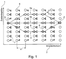
- possible state curves 4, 5a, and 5b are shown, which were calculated from a start state S to a destination state Z within a finite search space 3 for a state variable 1 (eg vehicle speed) within a model-based predictive control method.
- a first course is represented by the line 4 connecting the black dots 9.
- Further possible courses are shown by way of example by the lines 5a and 5b, which connect the vertical and horizontal striped state points (speed points).
- the search space 3 is discretized, d. h., a discrete value range in the form of the state points 6 is specified for all possible speed profiles.
- the step size or sampling rate for the different values of the state variable is indicated by s2.
- the search space is also discretized in the direction of the horizon axis 2, the step size is indicated by s1.
- the optimal velocity profile within the current prediction horizon 2 is determined by the current value of the state variable, e.g. B. the current driving speed specified.
- the target state Z will also specify, for. By estimation.
- the future dynamic behavior of the system state over the current prediction horizon is predicted, ie predicted.
- each state transition indicated by the arrows in FIG. 1 , with respect to the target criteria (eg the fuel demand for a speed change) by means of a target function.
- the optimal trajectory is determined from the possible trajectories of the state variable.
- the line 4 should represent the optimal trajectory, ie, for example, indicate the speed profile with the lowest fuel demand in the forward distance horizon 2.
- Such optimization methods work with sliding prediction horizons, i. That is, after elapse of a time interval, a new prediction is started based on the currently measured or estimated new state, but shifted by one time step.
- the new prediction horizon thus begins a time step later, and therefore also extends a time step further into the future, so it is also spoken of a gliding horizon. Due to the continuous inclusion of the current system status and the continuously recalculated optimum control, a closed control loop is obtained instead of an open control.
- a search space can be defined by one or more state variables. However, the larger the prediction horizon (forecast horizon), the greater the optimization potential.
- a disadvantage of such online optimization methods is known to be the high computational complexity due to the calculation of all (possible) state transitions. Due to limited computational resources and computing time in the online optimization, it would therefore be desirable to limit the search space.
- a disadvantage of this approach is that the restrictions of the search space that can be achieved with it are rather small, in particular for longer prediction horizons, since the proposed edge trajectories usually still cover a large part of the overall search space.
- Another disadvantage is the comparatively high computation required to determine the reduced state space, whereby savings in computational effort in the actual downstream optimization process are partially canceled.
- the invention is based on the technical knowledge that purely on the basis of suitable route information of the route ahead in the prediction horizon and without the use of the optimizer already an estimate of the course of the state variable to be optimized in the prediction horizon can be performed, which is sufficiently accurate to them for search space restriction use.
- the invention thus proposes a method for restricting a search space for a model-based online optimization method.
- the model-based on-line optimization method whose search space is restricted is a method that determines a predicted optimal course of a state quantity (system size) of a vehicle within a given search space for a preceding link.
- This course determined by the optimization method is referred to below as the first course in order to distinguish it from a second course according to the invention, which is determined on the basis of route information and not by means of the optimization method.
- the online optimization method is preferably a model-based predictive control method.
- the method for restricting the search space for the optimization method comprises the following steps: determining a predicted second course of the state variable along the preceding link depending on route information of the preceding link and restricting the search space depending on the determined predicted second course of the state variable.
- the thus restricted search space can then be used for the subsequent determination of the first course of the state variable in the context of the model-based online optimization method.
- the course of at least one state variable of the vehicle whose change can be attributed at least partially to one or more route information is thus estimated on the basis of the corresponding route information in order to determine an at least approximate course of the state variable.
- the search space for the subsequent, actual accurate Determination of the state variable can be restricted.
- the computation time of a subsequent optimization method can be restricted or, for the same computation time, a larger path horizon or a larger prediction horizon can be used for the optimization, which improves the quality of the optimization method.
- the estimated predicted second course of the state variable is thus not calculated using the model-based optimization method or the optimizer, but preferably only on the basis of route properties or route parameters of the preceding route section and their effects on the value of the state variable.
- the effect of a particular path property on the value of the state variable can be determined, for example, by a corresponding specification or calculation rule which indicates whether and how a particular value of the one or more route parameters changes the value of the at least one state variable.
- the route information indicates one or more properties of the route section that corresponds to the respective prediction horizon, for example, the gradient profile or elevation profile, the profile of the permissible maximum speed along the route section, curve radii of the curves and / or existing intersections along the route section.
- the method is suitable for restricting the search space of vehicle state variables whose change can be attributed to a route information or route property with sufficient accuracy.
- the state variable of the vehicle can be, for example, a state of charge of an energy store for providing electrical drive energy in a hybrid or electric drive train, hereinafter also referred to as traction energy storage.
- Another possible state quantity is the coolant temperature of a primary cooling circuit, e.g. an internal combustion engine, or the coolant temperature of a secondary cooling circuit, z. B. for hybrid components.
- Another possible state variable is the gear selection for an automated transmission or the speed selection for a cruise control.
- the invention is not limited to the above examples of state variables, but the invention can in principle be used to restrict a search space for all state variables or system variables which are to be predicted with a model-based optimization method in a prediction horizon and whose change along a route section in the prediction horizon can be attributed to a route information or track property sufficiently accurately.
- the state variable can in particular also be embodied as a multidimensional state variable and, for example, both the course of the state of charge of the traction energy storage and the speed profile, the course of the gear selection and / or the course of the coolant temperature specify.
- search space is understood to mean all state curves of at least one state variable within the prediction horizon to be optimized, which are possible at least on the basis of a start state of the at least one state variable and depending on a target state of the at least one state variable.
- the change in the value of the state variable or the value of the state variable assigned to each class can be determined offline by means of a simulation or a heuristic method.
- the class-specific function parameters which indicate how the class-specific path properties affect the state variable, can be simulated, e.g. Example by means of a simulation model, the dependence of the system behavior depending on the Streckenparamater used approximates, be determined.
- these class-specific function parameters can be specified heuristically, z. Based on experimental data.
- a particularly preferred possibility of the realization according to the invention provides that the division of the preceding route horizon into predetermined classes takes place at least as a function of a gradient course and / or a height profile of the route.
- the slope course along the route usually correlates strongly with the course of the state of charge of a traction energy storage, which will be explained in more detail below in the context of an embodiment.
- the gradient also correlates with the heat input into the one or more cooling circuits and thus with the coolant temperature.
- the slope curve also correlates strongly with the particular combination of engaged gear of an automated transmission and the speed selection.
- a first classification may be on the basis of slope data, and each gradient class may have a subclassification based on another route property, such as the maximum allowed speed.
- the accuracy of the estimation of the second course can be increased.
- a predicted target state of the second course i. H. the value of the state variable at the end of the underlying prediction horizon, specified as the target state for the subsequent optimization method. Since a starting state of the state variable at the beginning of the prediction horizon as well as a destination state at the end of the prediction horizon must be specified as default for the subsequent optimization method, a particular advantage of this variant is thus that the estimation of the course of the state variable according to the invention automatically provides a good estimate provides the destination state.
- a further embodiment is characterized in that a first search space boundary is determined by shifting the predicted second course of the state variable by a positive first offset. Furthermore, by shifting the predicted second curve of the state variable by a negative second offset, a second search space boundary can be obtained be determined.
- the constrained search space for the state variable includes all state size values within the first and second search space boundaries for the current prediction horizon. According to this variant, the search space is thus restricted in the form of a search band, within which runs the particular predicted second course of the state variable. If the first and second offset are chosen to be the same size, the second course of the state variable runs centrally in the search band.
- the offsets are sufficiently large to be chosen so that the trajectory of the optimal state history with a high probability will be completely within the search band. For example, a suitable size of the offsets can be determined beforehand on the basis of test simulations.
- the offsets on the prediction horizon may be constant or variable.
- the offsets and thus the distance of the search space boundaries from the second course of the state variable are variable. It is advantageous here to change the distance of the search space boundaries from the predicted second course of the state variable as a function of a variable which indicates a measure of the magnitude of a change in the predicted second course of the state variable.
- This variable can be, for example, the first and / or second derivative of the function, which describes the second course of the state variable in the prediction horizon.
- the search space boundaries can be set, for example, such that they each have sections with at least two different distances to the predicted second course of the state variable, wherein the greater distance is selected for those sections of the preceding route horizon in which the predicted second course of the state variable changes more as in the sections with smaller distance.
- This variant offers the advantage that the restriction of the search space is adapted dynamically to the estimated strength or fluctuation of the state variable. According to this aspect, in areas of the prediction horizon in which a large variation or change of state quantity is expected, the search space is less restricted than in areas where smaller variations or changes are expected. This is based on the knowledge that the accuracy of the prediction of the second course is less accurate in the areas of large variation.
- the search space is preferably discretized, ie, a discrete value range of the state variable in the prediction horizon will be specified. Furthermore, the sampling frequency along the Horizon axis in discrete steps.
- the discrete search space is thus formed by individual state points in the search space, which come into question as possible values for the state variable in the context of the optimization method.
- a vertical or horizontal spacing of the search space points it is also possible within the scope of the invention for a vertical or horizontal spacing of the search space points to be changed in dependence on a quantity which indicates a measure of the magnitude of a change in the predicted second course of the state variable.
- the first and / or the second derivative of the function which indicates the course of the state variable in the prediction horizon, can again be used.
- One way to constrain search space is to increase the distance of the search space points in those areas where the predicted second history of the state variable changes less than a predetermined threshold. As a result, the sampling resolution for the subsequent optimization method in these areas is lowered, which increases the computational effort.
- the search space restriction does not take place by a reduction of the search space boundaries, but by a reduction of the number of search space points in the areas where the predicted second course of the state variable does not change greatly.
- the aforementioned method concerns the restriction of a search space for a model-based on-line optimization method, but not the optimization method itself, d. h.
- limited search space can then a generic model-based online optimization method, eg. B. a known model-based predictive control method of a motor vehicle, be given as input data.
- the invention can be used to specify a restricted search space for any generic and per se known model-based online optimization method, wherein the respective prediction horizons and state variables must of course be the same.
- a further aspect of the invention relates to a model-based on-line optimization method, in particular a model-based predictive control method, in which the search space is restricted according to a method as described herein.
- Another aspect of the invention relates to a motor vehicle, in particular a commercial vehicle, comprising a model-based online optimizer, in particular a model-based predictive controller arranged to restrict the search space for performing the model-based online optimization method as described herein.
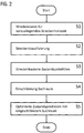
- FIG. 2 shows a schematic flow diagram illustrating a method for determining a restricted search space according to an embodiment of the invention.
- the embodiment illustrates the invention by way of example for the state of charge of the traction energy store as an exemplary state variable, the course of which is predicted (predicted) on the basis of route data.
- the slope data or the elevation profile of the route is used since a change in the state of charge for the purposes of predicting an approximate state of the state of charge for the search space restriction sufficiently accurately attributable to the slope data or the altitude profile.
- the state of charge of an electrical energy store in a hybrid vehicle is predicted purely on the basis of slope data of a route ahead. Simulative studies have shown that the state of charge of the energy store has a similarity to the slope profile of the route. Accordingly, the method simulates a complex operating strategy for the hybrid drive train with sufficient accuracy purely on the basis of slope data by predicating the state of charge of the energy store.
- step S1 for the route section which corresponds to the current route or prediction horizon 2, the associated route profile data 15 is determined, which in particular indicates the gradient course along the route or its altitude profile.
- This data can be determined, for example, based on the map data of a navigation device.
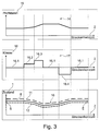
- a route profile 14 is created, as for example in the upper diagram of FIG. 3 is illustrated.
- the route profile can be composed of different information.
- the route profile data 15 for increasing the prediction accuracy of the estimated course of the state variable in addition to the slope data, may also contain data concerning further route properties from which a state of charge change can be predicted.
- An example of this are speed limits on the track.
- the route profile is subdivided into different phases depending on the determined route profile data 15, each corresponding to a class 16 whose delimitation is performed by fixed gradient limits.
- the subdivision takes place as a function of the slope data, so that a sequence 17 of classes 16 along the route section 2 results and thus a discrete class profile. This is in the middle diagram of the FIG. 3 shown.
- a mean expected memory performance is defined. With positive gradients, the memory performance is negative because energy is taken from the memory in these phases. Negative slopes define positive storage performance. In these phases Energy is supplied to the storage. In addition, in this example, there is also a phase in which the storage power corresponds to 0 kW, ie, in this phase, the state of charge of the memory undergoes no change.
- the classification of the classes is in FIG. 4 exemplified. As in FIG. 4 recognizable, here are five classes for the route classification pretend.
- a first class (“10") 16.3, which divides all sections of track that have a slope greater than or equal to 5%, as indicated in the second and third column of the classification table FIG. 4 is recognizable.
- a second class (“5") 16.2, which divides all sections that have a slope greater than or equal to 0% and less than 5%.
- a third class (“0") 16.1 which divides all sections that have a slope greater than or equal to -1% and less than 0%.
- a fourth class (“-5"), which divides all sections of track that have a grade equal to or greater than -3% and less than -1%, and a fifth grade (“-10”) 16.4, which divides all sections that have an incline of less than -3%.
- Each class is assigned a specific function for state prediction.
- this function assigns a mean change in the value of the state variable for each class, here the state of charge, which is shown in column 18 of the table of FIG. 4 is shown.
- the values of column 18 indicate at which power per unit time the memory is being charged or discharged.
- the memory is unloaded, for example, at sections with steep slopes of greater than or equal to 5% per time or distance unit according to the vehicle-specific simulation model with an average of 100 kW.
- the accumulator is discharged at 50 kW per unit of time or distance.
- the store is charged at slopes of greater than 3% per unit of time or distance of 100 KW. Due to the power and the duration of the phase results in an amount of energy that is supplied to the memory or withdrawn. This therefore corresponds to the state change of the state of charge.
- the values of column 18 are determined in advance heuristically or on the basis of simulation results. In the present case, these values depend on the respective drive train configuration and the operating strategy of the traction energy storage device, which are mapped within the scope of the simulation model.
- the distance-dependent state profiles are determined and a classification is defined on the basis of these results. For each class, one is based on the route-specific parameters Derived function that maps the course of the system state with sufficient accuracy. By means of function parameters that can be parameterized online in the vehicle, deviations between real operation and the simulation results during runtime in the vehicle can additionally be minimized.
- the division into different classes allows a fine graduation of the state prediction. Each class represents a degree of change of state. Depending on the degree, the state changes in the positive or negative direction or experiences no change.
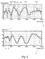
- FIG. 5 By way of example, another example of a route classification is shown, which is based on the classification table of FIG. 4 was made.
- the curve designated by the reference numeral 19 represents the course of the road gradient in the track horizon 2.
- the stair curve designated by the reference numeral 17 represents the route classification according to the classification table.
- the classification results in a sequence of classes 16.
- step S3 a distance-based prediction of the course of the state of charge in the prediction horizon then takes place.
- a state prediction is calculated for each class on the basis of the stored function or classification table.
- Each of the classes 16 is active for a certain amount of time in the horizon. This results from the slope course of the distance and is in FIG. 5 illustrated by the different widths of the individual class sections in the direction of the axis of the route horizon 2.
- the distance-based state of charge curve 8 which for the general example of FIG. 3 in the lower diagram is shown as curve 8 and for the example of the state of charge curve in the lower diagram of FIG. 5 also represented by the curve 8.
- the result of the calculations is thus the predicted state course 8, which was determined purely on the basis of route information and its effects on the state of charge.
- step S4 a restriction of the search space then ensues for the subsequent optimization method, which according to the exemplary embodiment is a model-based predictive control method.
- the hysteresis represented by curves 11 and 12 in the lower diagram of FIG. 3 then defined the reduced search space 10 for the downstream optimization process.
- the search space boundaries 11, 12 can be determined, for example, by shifting the predicted second course 8 of the state variable by an offset in the positive and negative directions, resulting in a search space band 10 whose height profile corresponds to the course 8 of the predicted state variable.
- the offset should be selected to be sufficiently large that the optimal course of the state variable is also within the offset limits, so that it can be determined by the subsequent optimization method within the restricted search space 10.
- the optimization method calculates the optimal state course within the route horizon on the basis of detailed mathematical models (step S5).
- the optimization method thus calculates the optimum course 4 of the state variable within the respective current prediction horizon of the sliding prediction horizon with regard to the specified target function.
- the predefined starting value S of the state of charge curve is again the current state of charge at the beginning of the prediction horizon 2.
- the final value E determined using the distance-based prediction method is specified as the target value Z for the optimization method.
- the method is preferably optimized so far by means of simulative and heuristic investigations until a sufficient accuracy in the prediction of the state of charge history is achieved.
- the search space of a downstream optimization process can hereby be decisively restricted.
- the downstream model-based online optimization method is not the subject of the invention and therefore not described in detail here.
- the inventive method for restricting the search space can also be used with any such optimization method, since only the specification of the search space is changed.
Landscapes
- Engineering & Computer Science (AREA)
- Automation & Control Theory (AREA)
- Transportation (AREA)
- Mechanical Engineering (AREA)
- Chemical & Material Sciences (AREA)
- Combustion & Propulsion (AREA)
- Health & Medical Sciences (AREA)
- Artificial Intelligence (AREA)
- Computer Vision & Pattern Recognition (AREA)
- Evolutionary Computation (AREA)
- Medical Informatics (AREA)
- Software Systems (AREA)
- Physics & Mathematics (AREA)
- General Physics & Mathematics (AREA)
- Human Computer Interaction (AREA)
- Traffic Control Systems (AREA)
Abstract
Description
- Die Erfindung betrifft ein Verfahren zur Suchraumeinschränkung eines modellbasierten Online-Optimierungsverfahrens zur Prädiktion einer Zustandsgröße eines Fahrzeugs. Das Verfahren betrifft insbesondere ein Verfahren zur Einschränkung eines Suchraums für ein modellbasiertes Online-Optimierungsverfahren, das einen prädizierten optimalen Verlauf einer Zustandsgröße eines Fahrzeugs innerhalb eines vorgegebenen Suchraums für einen Prädiktionshorizont bestimmt.
- In den letzten Jahren haben Assistenzsysteme in Fahrzeugen vermehrt Einzug gehalten, um insbesondere Sicherheit, Effizienz und Komfort zu erhöhen. Aus der Praxis ist bekannt, dass insbesondere bei Fahrzeugen, die einen hohen Grad der Automatisierung ermöglichen, z. B. Fahrzeuge mit automatisierter Getriebesteuerung, automatisierter Längsdynamikregelung bei aktivem Tempomat, automatisierter Momentenverteilung bei Hybridfahrzeugen, etc., für die Steuerverfahren vermehrt Online-Optimierungsverfahren bzw. Online-Optimierer unter Ausnutzung vorausschauender Informationen zum Einsatz kommen.
- Primäres Ziel des Optimierers ist die Berechnung von Stellgrößen (Steuereingriffen), um bestimmte Zustandsgrößen bzw. Systemzustände des Fahrzeugs wie z. B. die Fahrzeuggeschwindigkeit oder den Ladezustand des Energiespeichers, stets in ein Optimum zu überführen. Das Optimum für einen prädizierten Zustandsverlauf ist durch .Zielkriterien charakterisiert. Zielkriterien sind beispielsweise die Maximierung des Kraftstoffeinsparpotentials oder die Minimierung von Geräuschemissionen unter Vorgabe weiterer Randbedingungen, z. B. einer Mindestzeit für das Durchfahren einer Fahrstrecke.
- Ziel der Optimierung ist, innerhalb eines Suchraums den einen optimalen Pfad, auch Trajektorie genannt, zu finden, der ein Optimum hinsichtlich der Zielkriterien darstellt. Der Suchraum wird auch als Zustandsraum bezeichnet. Der Suchraum (Zustandsraum) ist zunächst definiert durch die Anzahl der Abtastschritte der Zustandsgröße multipliziert mit der Anzahl der Horizont-Abtastschritte. Dies ist der theoretisch mögliche Suchraum. Durch Vorgabe eines Startwerts und eines Zielwerts für den Verlauf der Zustandsgröße kann der mögliche Suchraum bereits eingeschränkt werden. Die Optimierung ermittelt den optimalen Verlauf der Zustandsgröße anhand der im Suchraum möglichen Zustandsverläufe, d. h. den Verläufen der zu optimierenden Zustandsgröße bzw. Systemgröße von einem Start- zu einem Zielzustand innerhalb der Suchraumgrenzen im aktuellen Prädiktionshorizont. Der Prädiktionshorizont wird auch als Vorhersagehorizont bezeichnet.
- Ein Beispiel für derartige Optimierungsverfahren ist die modellbasierte prädiktive Regelung, die an sich aus dem Stand der Technik bekannt ist und seit den 70er-Jahren erfolgreich zur Regelung verschiedenster technischer Prozesse eingesetzt wird. Zum Stand der Technik betreffend die modellbasierte prädiktive Regelung wird beispielhaft auf folgende beide Veröffentlichungen verwiesen: J. M. Maciejowski. Predictive Control with Constraints. Prentice Hall, New Jersey, 2002 und James B. Rawlings. Tutorial Overview of Model Predictive Control. IEEE Control Systems Magazine, 2000.
- Ferner ist aus der Praxis und dem Stand der Technik bekannt, dass die modellbasierte prädiktive Regelung in jüngerer Zeit auch vermehrt zur Online-Optimierung von Zustandsgrößen bzw. Systemgrößen von Kraftfahrzeugen, insbesondere von Hybridfahrzeugen, eingesetzt wird. Beispielsweise wird hierbei der Antriebsstrang durch detaillierte Systemmodelle abgebildet, in die Wirkungsgradbetrachtungen, thermische Modelle und Lebensdauerbetrachtungen der Systemkomponenten etc. einfließen. Ausgehend vom einem aktuellen Zeitpunkt und einem aktuellen Wert der Zustandsgröße(n) wird unter Verwendung des System modells das zukünftige dynamische Verhalten des Systemzustands über einen endlichen Prädiktionshorizont prädiziert. Die möglichen Trajektorien der zu optimierenden Zustandsgröße bzw. Systemgröße werden mit einem Zielfunktional bewertet und diejenige als Optimaltrajektorie ausgewählt, die ein vorgegebenes Gütemaß gemäß der Zielkriterien minimiert. Beispielhaft wird hierzu auf die Veröffentlichungen [1]: BACK, M. : Prädiktive Antriebsregelung zum energieoptimalen Betrieb von Hybridfahrzeugen, Universitätsverlag Karlsruhe, Diss., 2005 und [2]: BECK, R. ; BOLLIG, A. ; ABEL, D. : Echtzeitstrategien zum Prädiktiven Optimalen Energiemanagement in Hybridfahrzeugen. VDI-Berichte Nr. 1975 (2006), S. 557-560 verwiesen.
- In
Figur 1 sind beispielhaft mögliche Zustandsverläufe 4, 5a, und 5b gezeigt, die im Rahmen eines modellbasierten prädiktiven Regelverfahrens von einem Startzustand S zu einem Zielzustand Z innerhalb eines endlichen Suchraumes 3 für eine Zustandsgröße 1 (z. B. Fahrzeuggeschwindigkeit) berechnet wurden. Ein erster Verlauf ist durch die die schwarzen Punkte 9 verbindende Linie 4 dargestellt. Weitere mögliche Verläufe sind beispielhaft durch die Linien 5a bzw. 5b dargestellt, die die vertikal bzw. horizontal gestreiften Zustandspunkte (Geschwindigkeitspunkte) verbinden. - Der Suchraum 3 ist diskretisiert, d. h., es wird ein diskreter Wertebereich in Form der Zustandspunkte 6 für alle möglichen Geschwindigkeitsverläufe vorgegeben. Die Schrittweite bzw. Abtastrate für die unterschiedlichen Werte der Zustandsgröße ist mit s2 angegeben. Der Suchraum ist in Richtung der Horizontachse 2 ebenfalls diskretisiert, die Schrittweite ist mit s1 angegeben.
- Gesucht ist der in Abhängigkeit von vorgegebenen Zielkriterien und Randbedingungen optimale Geschwindigkeitsverlauf innerhalb des aktuellen Prädiktionshorizontes 2, ausgehend von dem aktuellen Startzustand S und einem Zielzustand Z. Der aktuelle Startzustand S ist durch den aktuellen Wert der Zustandsgröße, z. B. der aktuellen Fahrgeschwindigkeit, vorgegeben. Der Zielzustand Z wird ebenfalls vorgeben, z. B. durch Schätzung.
- Im Rahmen der Optimierung wird unter Verwendung eines Systemmodells das zukünftige dynamische Verhalten des Systemzustands über dem aktuellen Prädiktionshorizont prädiziert, d. h. vorhergesagt. Hierbei wird jeder Zustandsübergang, angedeutet durch die Pfeile in
Figur 1 , hinsichtlich der Zielkriterien (z. B. der Kraftstoffbedarf für eine Geschwindigkeitsänderung) mittels eines Zielfunktionals bewertet. Aus den möglichen Trajektorien der Zustandsgröße wird die optimale Trajektorie bestimmt. Im Beispiel derFigur 1 soll die Linie 4 die optimale Trajektorie darstellen, d. h. z. B. den Geschwindigkeitsverlauf mit dem geringsten Kraftstoffbedarf in dem vorausliegenden Streckenhorizont 2 angeben. - Derartige Optimierungsverfahren arbeiten mit gleitenden Prädiktionshorizonten, d. h., nach Verstreichen eines Zeitintervalls wird basierend auf dem aktuell gemessenen oder geschätzten neuen Zustand eine neue Prädiktion gestartet, die jedoch um einen Zeitschritt verschoben ist. Der neue Prädiktionshorizont beginnt somit einen Zeitschritt später und reicht demzufolge auch einen Zeitschritt weiter in die Zukunft, es wird daher auch von einem gleitenden Horizont gesprochen. Durch das fortlaufende Miteinbeziehen des aktuellen Systemzustands und durch die fortlaufend neu berechnete optimale Ansteuerung wird so anstelle einer offenen Steuerung ein geschlossener Regelkreis erhalten.
- Ein Vorteil derartiger Online-Optimierungsverfahren ist die Berechnung eines global optimalen Zustandsverlaufs innerhalb des definierten Suchraums. Ein Suchraum kann durch eine oder mehrere Zustandsgrößen definiert sein. Je größer jedoch der Prädiktionshorizont (Vorausschau-Horizont) gewählt wird, desto größer ist das Optimierungspotential.
- Ein Nachteil derartiger Online-Optimierungsverfahren ist bekanntermaßen der hohe Rechenaufwand aufgrund der Berechnung aller (möglichen) Zustandsübergänge. Aufgrund begrenzter Rechenressourcen und Rechenzeit bei der Online-Optimierung wäre es daher wünschenswert, den Suchraum einzuschränken.
- Ein aus der Praxis bekannter Ansatz ist die Verkürzung des Prädiktionshorizontes. Dies reduziert jedoch die Güte des Optimierungsergebnisses.
- In der Veröffentlichung [1] wird stattdessen vorgeschlagen, den Gesamtzustandsraum (Suchraum) einzuschränken, wobei ausgehend vom aktuellen Startzustand ein erreichbarer Zustandsraum berechnet wird und wobei unter der Annahme, dass der Zielzustand erreicht werden muss, ein zielführender Zustandsraum berechnet wird. Die Berechnung erfolgt mittels unterer und oberer Randtrajektorien, die diejenigen Zustände kennzeichnen, die auf Basis der Systemeigenschaften eine maximal mögliche Entfernung vom Start- bzw. Zielzustand darstellen. Anschließend wird ein reduzierter Zustandsraum aus der Schnittmenge von erreichbarem und zielführendem Zustandsraum bestimmt, der als eingeschränkter Suchraum dem Optimierungsverfahren zu Grunde gelegt wird.
- Nachteilig an diesem Ansatz ist, dass die damit erzielbaren Einschränkungen des Suchraums eher klein sind, insbesondere bei längeren Prädiktionshorizonten, da die vorgeschlagenen Randtrajektorien in der Regel noch einen großen Teil des Gesamtsuchraums abdecken. Ein weiterer Nachteil ist der vergleichsweise hohe Rechenaufwand, der zur Bestimmung des reduzierten Zustandsraums erforderlich ist, wodurch Einsparungen im Rechenaufwand beim eigentlichen nachgelagerten Optimierungsverfahren teilweise wieder aufgehoben werden.
- Es ist somit eine Aufgabe der Erfindung, ein verbessertes Verfahren zur Suchraumeinschränkung eines modellbasierten Online-Optimierungsverfahrens zur Prädiktion einer Zustandsgröße eines Fahrzeugs bereitzustellen, mit dem Nachteile herkömmlicher Techniken vermieden werden können. Es ist insbesondere eine Aufgabe der Erfindung, ein Verfahren zur Suchraumeinschränkung bereitzustellen, mit dem eine möglichst große Suchraumeinschränkung ermöglicht wird und mit dem eine Beeinträchtigung der Güte des Optimierungsergebnisses eines nachfolgenden Optimierungsverfahrens vermieden oder zumindest klein gehalten werden kann.
- Diese Aufgaben werden durch ein Verfahren mit den Merkmalen des Hauptanspruchs gelöst. Vorteilhafte Ausführungsformen und Anwendungen der Erfindung ergeben sich aus den abhängigen Ansprüchen und werden in der folgenden Beschreibung unter teilweiser Bezugnahme auf die Figuren näher erläutert.
- Die Erfindung beruht auf der technischen Erkenntnis, dass rein auf Basis von geeigneten Streckeninformationen der vorausliegenden Fahrtstrecke im Prädiktionshorizont und ohne Verwendung des Optimierers bereits eine Abschätzung des Verlaufs der zu optimierenden Zustandsgröße im Prädiktionshorizont durchgeführt werden kann, die hinreichend genau ist, um sie zur Suchraumeinschränkung zu verwenden.
- Erfindungsgemäß wird somit ein Verfahren zur Einschränkung eines Suchraums für ein modellbasiertes Online-Optimierungsverfahren vorgeschlagen. Das modellbasierte Online-Optimierungsverfahren, dessen Suchraum eingeschränkt wird, ist insbesondere ein Verfahren, das einen prädizierten optimalen Verlauf einer Zustandsgröße (Systemgröße) eines Fahrzeugs innerhalb eines vorgegebenen Suchraums für einen vorausliegenden Streckenabschnitt bestimmt. Dieser durch das Optimierungsverfahren bestimmte Verlauf wird nachfolgend als erster Verlauf bezeichnet, um diesen von einem erfindungsgemäßen zweiten Verlauf zu unterscheiden, der auf Basis von Streckeninformationen und nicht mittels des Optimierungsverfahrens ermittelt wird. Das Online-Optimierungsverfahren ist vorzugsweise ein modellbasiertes prädiktives Regelverfahren.
- Gemäß allgemeinen Gesichtspunkten der Erfindung umfasst das Verfahren zur Einschränkung des Suchraums für das Optimierungsverfahren die folgenden Schritte: Bestimmen eines prädizierten zweiten Verlaufs der Zustandsgröße entlang des vorausliegenden Streckenabschnitts in Abhängigkeit von Streckeninformationen des vorausliegenden Streckenabschnitts und Einschränken des Suchraums in Abhängigkeit von dem bestimmten prädizierten zweiten Verlauf der Zustandsgröße. Der so eingeschränkte Suchraum kann dann für die nachfolgende Bestimmung des ersten Verlaufs der Zustandsgröße im Rahmen des modellbasierten Online-Optimierungsverfahrens verwendet werden.
- Erfindungsgemäß wird somit der Verlauf von mindestens einer Zustandsgröße des Fahrzeugs, deren Veränderung sich auf eine oder mehrere Streckeninformationen zumindest teilweise zurückführen lässt, anhand der entsprechenden Streckeninformationen abgeschätzt, um einen zumindest ungefähren Verlauf der Zustandsgröße zu bestimmen. Anhand dieses abgeschätzten Verlaufs kann der Suchraum für die nachfolgende, eigentliche genaue Bestimmung der Zustandsgröße eingeschränkt werden. Somit kann die Rechenzeit eines nachfolgenden Optimierungsverfahrens eingeschränkt werden oder bei gleicher Rechenzeit ein größerer Streckenhorizont bzw. ein größerer Prädiktionshorizont zur Optimierung herangezogen werden, was die Güte des Optimierungsverfahrens verbessert.
- Der abgeschätzte prädizierte zweite Verlauf der Zustandsgröße wird somit nicht unter Verwendung des modellbasierten Optimierungsverfahrens bzw. des Optimierers berechnet, sondern vorzugsweise nur auf Basis von Streckeneigenschaften bzw. Streckenparametern des vorausliegenden Fahrtstreckenabschnitts und deren Auswirkungen auf den Wert der Zustandsgröße. Die Auswirkung einer bestimmten Streckeneigenschaft auf den Wert der Zustandsgröße kann beispielsweise durch eine entsprechende Vorgabe oder Berechnungsvorschrift ermittelt werden, die angibt, ob und wie ein bestimmter Wert des einen oder der mehreren Streckenparameter den Wert der mindestens einen Zustandsgröße verändert.
- Gemäß einer besonders bevorzugten Ausführungsform des Verfahrens umfasst die Bestimmung des prädizierten zweiten Verlaufs der Zustandsgröße die folgenden Schritte:
- Eine Ermittlung von Streckendaten für den vorausliegenden Streckenabschnitt, der dem aktuellen Prädiktionshorizont entspricht. Ferner eine anschließende Einteilung des vorausliegenden Streckenabschnitts in vorbestimmte Klassen in Abhängigkeit von den ermittelten Streckendaten, so dass sich eine Abfolge von Klassen entlang des Streckenabschnittes ergibt. Jeder Klasse wird entweder ein Wert der Zustandsgröße oder eine Änderung des Werts der Zustandsgröße bzw. ein Grad der Zustandsänderung der Zustandsgröße zugeordnet, insbesondere eine Relativänderung und/oder ein Absolutwert der Zustandsgröße. Schließlich umfasst die Ausführungsform den Schritt der Bestimmung des prädizierten zweiten Verlaufs der Zustandsgröße anhand der Werte und/oder Änderungen der Werte der Zustandsgröße für die Abfolge von Klassen entlang des Streckenabschnittes. Ein besonderer Vorzug dieses Klassifizierungsansatzes ist, dass hiermit der prädiktive zweite Verlauf schnell und mit vergleichsweise wenig Rechenaufwand abgeschätzt werden kann.
- Die Streckeninformation, beispielweise in Form von streckenspezifischen Parametern und/oder Streckendaten, gibt eine oder mehrere Eigenschaften des Streckenabschnitts, der dem jeweiligen Prädiktionshorizont entspricht, an, beispielsweise deren Steigungsverlauf bzw. Höhenprofil, den Verlauf der zulässigen Höchstgeschwindigkeit entlang des Streckenabschnitts, Kurvenradien der Kurven und/oder vorhandene Kreuzungen entlang des Streckenabschnitts.
- Vorstehend wurde bereits erwähnt, dass sich das Verfahren zur Einschränkung des Suchraums von Fahrzeugzustandsgrößen eignet, deren Änderung sich auf eine Streckeninformation bzw. Streckeneigenschaft hinreichend genau zurückführen lässt.
- Die Zustandsgröße des Fahrzeugs kann beispielsweise ein Ladezustand eines Energiespeichers zur Bereitstellung elektrischer Antriebsenergie in einem Hybrid- oder Elektroantriebsstrang sein, nachfolgend auch als Traktionsenergiespeicher bezeichnet. Eine andere mögliche Zustandsgröße ist die Kühlmitteltemperatur eines Primärkühlkreislaufs, z.B. eines Verbrennungsmotors, oder die Kühlmitteltemperatur eines Sekundärkühlkreislaufs, z. B. für Hybrid-Komponenten. Eine weitere mögliche Zustandsgröße ist die Gangwahl für ein automatisiertes Getriebe oder die Geschwindigkeitswahl für einen Tempomaten.
- Dem Fachmann ist klar, dass die Erfindung nicht auf die vorstehenden Beispiele von Zustandsgrößen beschränkt ist, sondern die Erfindung prinzipiell zur Einschränkung eines Suchraumes für alle Zustandsgrößen bzw. Systemgrößen verwendet werden kann, die mit einem modellbasierten Optimierungsverfahren in einem Prädiktionshorizont vorhergesagt werden sollen und deren Änderung entlang eines Streckenabschnitts im Prädiktionshorizont sich auf eine Streckeninformation bzw. Streckeneigenschaft hinreichend genau zurückführen lassen.
- Die Zustandsgröße kann insbesondere auch als mehrdimensionale Zustandsgröße ausgeführt sein und beispielsweise sowohl den Verlauf des Ladezustands des Traktionsenergiespeichers als auch den Geschwindigkeitsverlauf, den Verlauf der Gangwahl und/oder den Verlauf der Kühlmitteltemperatur angeben.
- Unter dem Begriff Suchraum werden alle Zustandsverläufe mindestens einer Zustandsgröße innerhalb des zu optimierenden Prädiktionshorizontes verstanden, die zumindest ausgehend von einem Startzustand der mindestens einen Zustandsgröße und in Abhängigkeit von einem vorzugebenen Zielzustand der mindestens einen Zustandsgröße möglich sind.
- Gemäß einer weiteren Ausführungsform der Erfindung kann die jeder Klasse zugeordnete Änderung des Werts der Zustandsgröße oder der jeder Klasse zugeordnete Wert der Zustandsgröße offline mittels einer Simulation oder eines heuristischen Verfahrens ermittelt werden. Mit anderen Worten können die klassenspezifischen Funktionsparameter, die angeben, wie sich die klassenspezifischen Streckeneigenschaften auf die Zustandsgröße auswirken, simulativ, z. B. mittels eines Simulationsmodells, das die Abhängigkeit des Systemverhaltens in Abhängigkeit der verwendeten Streckenparamater näherungsweise nachbildet, bestimmt werden. Alternativ können diese klassenspezifischen Funktionsparameter heuristisch vorgeben werden, z. B. basierend auf experimentellen Daten.
- Eine besonders bevorzugte Möglichkeit der erfindungsgemäßen Realisierung sieht vor, dass die Einteilung des vorausliegenden Streckenhorizontes in vorbestimmte Klassen zumindest in Abhängigkeit von einem Steigungsverlauf und/oder einem Höhenprofil der Fahrtstrecke erfolgt. Beispielsweise korreliert der Steigungsverlauf entlang der Fahrtstrecke in der Regel stark mit dem Verlauf des Ladezustands eines Traktionsenergiespeichers, was nachfolgend noch im Rahmen eines Ausführungsbeispiels detaillierter erläutert wird. Der Steigungsverlauf korreliert ebenfalls mit dem Wärmeeintrag in den oder die Kühlkreisläufe und somit mit der Kühlmitteltemperatur. Der Steigungsverlauf korreliert ebenfalls stark mit der jeweiligen Kombination aus eingelegtem Gang eines automatisierten Getriebes und der Geschwindigkeitswahl.
- Es ist weiter vorteilhaft, zur Klassifizierung neben den Steigungsdaten ferner weitere Streckeneigenschaften zu verwenden, insbesondere die Berücksichtigung des Verlaufs der zulässigen Höchstgeschwindigkeit entlang des Streckenabschnitts. Beispielsweise kann eine erste Klassifizierung anhand von Steigungsdaten erfolgen, und jede Steigungsklasse kann eine Unterklassifizierung basierend auf einer anderen Streckeneigenschaft, beispielsweise der zulässigen Höchstgeschwindigkeit, aufweisen. Dadurch kann die Genauigkeit der Abschätzung des zweiten Verlaufs erhöht werden.
- Gemäß einer weiteren Ausführungsvariante der Erfindung wird ein prädizierter Zielzustand des zweiten Verlaufs, d. h. der Wert der Zustandsgröße am Ende des zu Grunde liegenden Prädiktionshorizontes, als Zielzustand für das nachfolgende Optimierungsverfahren vorgegeben. Da als Vorgabe für das nachfolgende Optimierungsverfahren jeweils ein Startzustand der Zustandsgröße zu Beginn des Prädiktionshorizontes als auch ein Zielzustand am Ende des Prädiktionshorizontes vorgegeben werden muss, liegt ein besonderer Vorzug dieser Ausführungsvariante somit darin, dass die erfindungsgemäße Abschätzung des Verlaufs der Zustandsgröße automatisch eine gute Schätzung für den Zielzustand bereitstellt.
- Eine weitere Ausführungsform ist dadurch gekennzeichnet, dass durch Verschieben des prädizierten zweiten Verlaufs der Zustandsgröße um einen positiven ersten Offset eine erste Suchraumgrenze festgelegt wird. Ferner kann durch Verschieben des prädizierten zweiten Verlaufs der Zustandsgröße um einen negativen zweiten Offset eine zweite Suchraumgrenze festgelegt werden. Gemäß dieser Ausführungsform umfasst der eingeschränkte Suchraum für die Zustandsgröße alle Werte der Zustandsgröße innerhalb der ersten und zweiten Suchraumgrenzen für den aktuellen Prädiktionshorizont. Gemäß dieser Variante wird der Suchraum somit in Form eines Suchbandes eingeschränkt, innerhalb dessen der bestimmte prädizierte zweite Verlauf der Zustandsgröße verläuft. Wenn der erste und zweite Offset gleich groß gewählt werden, verläuft der zweite Verlauf der Zustandsgröße mittig im Suchband. Die Offsets sind ausreichend groß so zu wählen, so dass die Trajektorie des optimalen Zustandsverlaufs mit einer hohen Wahrscheinlichkeit vollständig innerhalb des Suchbandes verlaufen wird. Beispielsweise kann eine zweckmäßige Größe der Offsets vorab anhand von Testsimulationen ermittelt werden. Die Offsets über den Prädiktionshorizont können konstant oder variabel sein.
- Bei einer vorteilhaften Variante dieser Ausgestaltungsform sind die Offsets und damit der Abstand der Suchraumgrenzen vom dem zweiten Verlauf der Zustandsgröße variabel. Vorteilhaft ist hierbei, den Abstand der Suchraumgrenzen vom prädizierten zweiten Verlauf der Zustandsgröße in Abhängigkeit von einer Größe zu verändern, die ein Maß für die Stärke einer Änderung des prädizierten zweiten Verlaufs der Zustandsgröße angibt.
- Diese Größe kann beispielsweise die erste und/oder zweite Ableitung der Funktion, die den zweiten Verlauf der Zustandsgröße im Prädiktionshorizont beschreibt, sein. Hierbei können die Suchraumgrenzen beispielsweise derart festgelegt werden, dass sie jeweils Abschnitte mit mindestens zwei unterschiedlichen Abständen zum prädizierten zweiten Verlauf der Zustandsgröße aufweisen, wobei der größere Abstand für diejenigen Abschnitte des vorausliegenden Streckenhorizonts gewählt wird, in denen sich der prädizierte zweite Verlaufs der Zustandsgröße stärker ändert als in den Abschnitten mit kleinerem Abstand.
- Diese Variante bietet den Vorteil, dass die Einschränkung des Suchraums dynamisch an die abgeschätzte Stärke bzw. Schwankung der Zustandsgröße angepasst wird. Gemäß diesem Aspekt wird in Bereichen des Prädiktionshorizonts, in denen eine große Schwankung oder Veränderung der Zustandsgröße erwartet wird, der Suchraum weniger stark eingeschränkt als in Bereichen, in denen kleinere Schwankungen oder Veränderungen erwartet werden. Dies beruht auf der Erkenntnis, dass die Genauigkeit der Prädiktion des zweiten Verlaufs in den Bereichen mit starker Schwankung weniger genau ist.
- Der Suchraum ist vorzugsweise diskretisiert, d. h., es wird ein diskreter Wertebereich der Zustandsgröße im Prädiktionshorizont vorgeben. Ferner kann die Abtastfrequenz entlang der Horizontachse in diskreten Schritten erfolgen. Der diskrete Suchraum wird somit durch einzelne Zustandspunkte im Suchraum gebildet, die als mögliche Werte für die Zustandsgröße im Rahmen des Optimierungsverfahrens in Frage kommen. Bei einem diskreten Suchraum besteht im Rahmen der Erfindung ferner die Möglichkeit, dass ein vertikaler oder horizontaler Abstand der Suchraumpunkte wiederum in Abhängigkeit von einer Größe verändert wird, die ein Maß für die Stärke einer Änderung des prädizierten zweiten Verlaufs der Zustandsgröße angibt. Hierzu kann beispielsweise wiederum die erste und/oder die zweite Ableitung der Funktion, die den Verlauf der Zustandsgröße im Prädiktionshorizont angibt, verwendet werden. Eine Möglichkeit zur Suchraumeinschränkung besteht darin, dass der Abstand der Suchraumpunkte in den Bereichen vergrößert wird, in denen sich der prädizierte zweite Verlauf der Zustandsgröße weniger stark als ein vorgegebener Schwellenwert ändert. Dadurch wird die Abtastauflösung für das nachfolgende Optimierungsverfahren in diesen Bereichen erniedrigt, wodurch sich der Rechenaufwand erhöht.
- Gemäß diesen Ausführungsvarianten erfolgt die Suchraumeinschränkung nicht durch eine Verkleinerung der Suchraumgrenzen, sondern durch eine Reduzierung der Zahl der Suchraumpunkte in den Bereichen, wo der prädizierte zweite Verlauf der Zustandsgröße sich nicht stark ändert.
- Es wird betont, dass das vorgenannte Verfahren die Einschränkung eines Suchraums für ein modellbasiertes Online-Optimierungsverfahren betrifft, nicht jedoch das Optimierungsverfahren selbst, d. h., der erfindungsgemäß eingeschränkte Suchraum kann dann einem gattungsgemäßen modellbasierten Online-Optimierungsverfahren, z. B. einem bekannten modellbasierten prädiktiven Regelverfahren eines Kraftfahrzeugs, als Eingabedaten vorgeben werden. Die Erfindung kann zur Vorgabe eines eingeschränkten Suchraums für jegliche gattungsgemäße und an sich bekannte modellbasierte Online-Optimierungsverfahren verwendet werden, wobei die jeweiligen Prädiktionshorizonte und Zustandsgrößen natürlich die gleichen sein müssen.
- Ein weiterer Gesichtspunkt der Erfindung betrifft ein modellbasiertes Online-Optimierungsverfahren, insbesondere ein modellbasiertes prädiktives Regelverfahren, bei dem der Suchraum gemäß einem Verfahren wie hierin beschrieben eingeschränkt wird.
- Ein weiterer Aspekt der Erfindung betrifft ein Kraftfahrzeug, insbesondere ein Nutzfahrzeug, aufweisend einen modellbasierten Online-Optimierer, insbesondere einen modellbasierten prädiktiven Regler, der eingerichtet ist, den Suchraum zur Durchführung des modellbasierten Online-Optimierungsverfahrens wie hierin beschrieben einzuschränken.
- Die zuvor beschriebenen bevorzugten Ausführungsformen und Merkmale der Erfindung sind beliebig miteinander kombinierbar. Weitere Einzelheiten und Vorteile der Erfindung werden im Folgenden unter Bezug auf die beigefügten Zeichnungen beschrieben. Es zeigen:
- Figur 1
- eine Ermittlung eines optimalen Verlaufs einer Zustandsgröße innerhalb eines nicht-eingeschränkten Suchraums;
- Figur 2
- ein schematisches Ablaufdiagramm zur Illustration eines Verfahrens zur Bestimmung eines eingeschränkten Suchraums gemäß einer Ausführungsform der Erfindung;
- Figur 3
- Diagramme zur Illustration einer streckenbasierten Klassifizierung und Zustandsprädiktion gemäß einer Ausführungsform der Erfindung;
- Figur 4
- eine Tabelle zur Illustration der streckenbasierten Klassifizierung und Zustandsprädiktion gemäß einer Ausführungsform der Erfindung am Beispiel des Ladezustands eines Energiespeichers als Zustandsgröße;
- Figur 5
- einen ersten Verlauf einer Zustandsgröße, ermittelt mit dem Optimierungsverfahren, und einen zweiten Verlauf, abgeschätzt mit einer streckenbasierten Zustandsprädiktion gemäß einer Ausführungsform der Erfindung; und
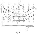
- Figur 6
- einen eingeschränkten Suchraum gemäß einer Ausführungsform der Erfindung.
- Gleiche oder äquivalente Komponenten sind in allen Figuren mit den gleichen Bezugszeichen bezeichnet.
-
Figur 2 zeigt ein schematisches Ablaufdiagramm zur Illustration eines Verfahrens zur Bestimmung eines eingeschränkten Suchraums gemäß einer Ausführungsform der Erfindung. - Die Ausführungsform illustriert die Erfindung exemplarisch für den Ladezustand des Traktionsenergiespeichers als beispielhafte Zustandsgröße, deren Verlauf anhand von Streckendaten prädiziert (vorhergesagt) wird. Als Streckenddaten werden die Steigungsdaten bzw. das Höhenprofil der Strecke verwendet, da sich eine Änderung des Ladezustands für die Zwecke einer Vorhersage eines ungefähren Verlaufs des Ladezustands zur Suchraumeinschränkung hinreichend genau auf die Steigungsdaten bzw. das Höhenprofil zurückführen lässt.
- Mit anderen Worten wird bei dem nachfolgenden Beispiel der Ladezustand eines elektrischen Energiespeichers in einem Hybrid-Fahrzeug rein auf Basis von Steigungsdaten einer vorausliegenden Strecke prädiziert. Simulative Untersuchungen haben gezeigt, dass der Ladezustand des Energiespeichers eine Ähnlichkeit zu dem Steigungsprofil der Strecke aufweist. Das Verfahren bildet demnach eine komplexe Betriebsstrategie für den Hybrid-Antriebsstrang hinreichend genau rein auf Basis von Steigungsdaten nach, indem es den Ladezustandsverlauf des Energiespeichers prädiziert.
- In Schritt S1 werden für den Streckenabschnitt, der dem aktuellen Strecken- bzw. Prädiktionshorizont 2 entspricht, die zugehörigen Streckenprofildaten 15 ermittelt, die insbesondere den Steigungsverlauf entlang der Strecke bzw. deren Höhenprofil angeben. Diese Daten können beispielsweise auf Basis der Kartendaten eines Navigationsgeräts bestimmt werden. Anhand der eingelesenen Streckendaten wird ein Streckenprofil 14 erstellt, wie es beispielsweise im oberen Diagramm der
Figur 3 illustriert ist. - Wie vorstehend bereits erwähnt, kann sich das Streckenprofil aus verschiedenen Informationen zusammensetzen. So können die Streckenprofildaten 15 zur Steigerung der Vorhersagegenauigkeit des abgeschätzten Verlaufs der Zustandsgröße neben den Steigungsdaten auch Daten enthalten, die weitere Streckeneigenschaften betreffen, aus denen sich eine Ladezustandsänderung vorhersagen lässt. Ein Beispiel hierfür sind Geschwindigkeitsbegrenzungen auf der Strecke.
- In Schritt S2 erfolgt anschließend eine Streckenklassifizierung anhand der Streckenprofildaten 15. Das Streckenprofil wird in Abhängigkeit von den ermittelten Streckenprofildaten 15 in verschiedene Phasen unterteilt, die jeweils einer Klasse 16 entsprechen, deren Abgrenzung durch feste Steigungsgrenzen vorgenommen wird. Vorliegend erfolgt die Unterteilung in Abhängigkeit von den Steigungsdaten, so dass sich eine Abfolge 17 von Klassen 16 entlang des Streckenabschnittes 2 ergibt und somit ein diskreter Klassenverlauf. Dies ist im mittleren Diagramm der
Figur 3 dargestellt. - Für jede Klasse wird eine mittlere zu erwartende Speicherleistung definiert. Bei positiven Steigungen ist die Speicherleistung negativ, da dem Speicher in diesen Phasen Energie entnommen wird. Negative Steigungen definieren eine positive Speicherleistung. In diesen Phasen wird dem Speicher Energie zugeführt. Zudem gibt es in diesem Beispiel auch eine Phase, in der die Speicherleistung 0 kW entspricht, d. h., in dieser Phase erfährt der Ladezustand des Speichers keine Änderung.
- Die Einteilung der Klassen ist in
Figur 4 beispielhaft erläutert. Wie inFigur 4 erkennbar, sind vorliegend fünf Klassen für die Streckenklassifizierung vorgeben. Eine erste Klasse ("10") 16.3, in die alle Streckenabschnitte eingeteilt werden, die eine Steigung größer gleich 5 % haben, was aus den Angaben der zweiten und dritten Spalte der Klassifizierungstabelle ausFigur 4 erkennbar ist. Eine zweite Klasse ("5") 16.2, in die alle Streckenabschnitte eingeteilt werden, die eine Steigung größer gleich 0 % und kleiner 5 % haben. Eine dritte Klasse ("0") 16.1, in die alle Streckenabschnitte eingeteilt werden, die eine Steigung größer gleich -1 % und kleiner 0 % haben. Eine vierte Klasse ("-5"), in die alle Streckenabschnitte eingeteilt werden, die eine Steigung größer gleich -3 % und kleiner -1 % haben, und eine fünfte Klasse ("-10") 16.4, in die alle Streckenabschnitte eingeteilt werden, die eine Steigung kleiner -3 % haben. - Jeder Klasse wird eine spezifische Funktion für die Zustandsprädiktion zugeordnet. Vorliegend ordnet diese Funktion für jede Klasse eine mittlere Änderung des Werts der Zustandsgröße zu, hier der Ladezustand, was in der Spalte 18 der Tabelle der
Figur 4 dargestellt ist. Die Werte der Spalte 18 geben an, mit welcher Leistung pro Zeiteinheit der Speicher geladen bzw. entladen wird. So wird der Speicher beispielsweise bei Streckenabschnitten mit starken Steigungen von größer gleich 5 % pro Zeit- oder Streckeneinheit gemäß dem fahrzeugspezifischen Simulationsmodell durchschnittlich mit 100 kW entladen. Bei Streckenabschnitten mit geringen Steigungen größer gleich 0 % und kleiner 5 % wird der Speicher pro Zeit- oder Streckeneinheit mit 50 kW entladen. Dagegen wird der Speicher aufgrund von Rekuperationseffekten bei Gefällen von größer 3 % pro Zeit- oder Streckeneinheit mit 100 KW geladen. Aufgrund der Leistung und der zeitlichen Dauer der Phase ergibt sich eine Energiemenge, die dem Speicher zugeführt oder entzogen wird. Dies entspricht somit der Zustandsänderung des Ladezustandes. - Die Werte der Spalte 18 werden vorab heuristisch oder anhand von Simulationsergebnissen ermittelt. Vorliegend hängen diese Werte von der jeweiligen Antriebsstrangkonfiguration und der Betriebsstrategie des Traktionsenergiespeichers ab, die im Rahmen des Simulationsmodells abgebildet sind. Bei der simulativen Bestimmung der Funktionen werden die streckenabhängigen Zustandsverläufe ermittelt und anhand dieser Ergebnisse eine Klasseneinteilung definiert. Für jede Klasse wird eine auf den streckenspezifischen Parametern basierende Funktion abgeleitet, die den Verlauf des Systemzustands hinreichend genau abbildet. Mittels online im Fahrzeug parametrierbarer Funktionsparameter können zusätzlich Abweichungen zwischen realem Betrieb und der Simulationsergebnisse zur Laufzeit im Fahrzeug minimiert werden. Die Einteilung in verschiedene Klassen ermöglicht eine feine Abstufung der Zustandsprädiktion. Jede Klasse steht hierbei für einen Grad der Zustandsänderung. Je nach Grad ändert sich der Zustand in positiver oder negativer Richtung bzw. erfährt keine Änderung.
- Im oberen Diagramm der
Figur 5 ist nochmal beispielhaft ein weiteres Beispiel für eine Streckenklassifizierung gezeigt, die anhand der Klassifizierungstabelle derFigur 4 vorgenommen wurde. Die mit dem Bezugszeichen 19 bezeichnete Kurve stellt den Verlauf der Fahrbahnsteigung im Streckenhorizont 2 dar. Die mit dem Bezugszeichen 17 bezeichnete Treppenkurve stellt die Streckenklassifizierung gemäß der Klassifizierungstabelle dar. Aufgrund der Klassifizierung ergibt sich eine Abfolge von Klassen 16. - In Schritt S3 erfolgt dann eine streckenbasierte Prädiktion des Verlaufs des Ladezustands im Prädiktionshorizont.
- Ausgehend von dem aktuellen Zustand zu Beginn des Streckenhorizontes, vorliegend somit dem aktuellen Ladezustand des Speichers zu Beginn des Streckenhorizontes, wird für jede Klasse auf Basis der hinterlegten Funktion oder Klassifizierungstabelle eine Zustandsprädiktion berechnet.
- Jede der Klassen 16 ist für eine bestimmte zeitliche Dauer im Horizont aktiv. Dies ergibt sich aus dem Steigungsverlauf der Strecke und ist in
Figur 5 anhand der unterschiedlichen Breiten der einzelnen Klassenabschnitte in Richtung der Achse des Streckenhorizonts 2 dargestellt. Durch Integration der mittleren Speicherleistungen über den gesamten Horizont ergibt sich der streckenbasierte Ladezustandsverlauf 8, der für das allgemeine Beispiel derFigur 3 im unteren Diagramm als Kurve 8 dargestellt ist und für das Beispiel des Ladezustandsverlauf im unteren Diagramm derFigur 5 ebenfalls durch die Kurve 8 dargestellt ist. Das Ergebnis der Berechnungen ist somit der prädizierte Zustandsverlauf 8, der rein auf Basis von Streckeninformationen und deren Auswirkungen auf den Ladezustand bestimmt wurde. - In Schritt S4 erfolgt anschließend eine Einschränkung des Suchraums für das nachfolgende Optimierungsverfahren, das gemäß dem Ausführungsbeispiel ein modellbasiertes prädiktives Regelverfahren ist.
- Ausgehend von dem prädizierten Zustandsverlauf 8 wird mittels einer Hysterese, dargestellt durch die Kurven 11 und12 im unteren Diagramm der
Figur 3 , anschließend der reduzierte Suchraum 10 für das nachgelagerte Optimierungsverfahren definiert. Die Suchraumgrenzen 11, 12 können beispielsweise durch Verschieben des prädizierten zweiten Verlaufs 8 der Zustandsgröße um einen Offset in positiver und negativer Richtung festgelegt werden, so dass sich ein Suchraumband 10 ergibt, dessen Höhenprofil dem Verlauf 8 der prädizierten Zustandsgröße entspricht. Der Offset sollte so ausreichend groß gewählt werden, dass der optimale Verlauf der Zustandsgröße sich auch innerhalb der Offsetgrenzen befindet, so dass dieser vom nachfolgenden Optimierungsverfahren innerhalb des eingeschränkten Suchraums 10 ermittelt werden kann. - Dies ist nochmals schematisch in
Figur 6 dargestellt. Es ist ersichtlich, dass der Suchraum 10 für das Optimierungsverfahren im Vergleich zum ursprünglichen Suchraum (siehe auchFigur 1 ) stark eingeschränkt werden kann. Alle Punkte 13 außerhalb der Grenzen 11, 12 des eingeschränkten Suchraums werden vom Optimierungsalgorithmus nicht mehr abgetastet, sondern nur noch diejenigen Punkte 7, die sich innerhalb der neuen Suchraumgrenzen 11, 12 befinden, so dass sich eine bedeutende Reduktion des Rechenaufwandes ergibt. - Innerhalb dieses reduzierten Suchraumes 10 berechnet das Optimierungsverfahren anhand detaillierter mathematischer Modelle den optimalen Zustandsverlauf innerhalb des Streckenhorizontes (Schritt S5). Das Optimierungsverfahren berechnet somit im Hinblick auf das vorgegebene Zielfunktional den optimalen Verlauf 4 der Zustandsgröße innerhalb des jeweils aktuellen Prädiktionshorizonts des gleitenden Prädiktionshorizontes. Der vorgegebene Startwert S des Ladezustandsverlaufs ist wiederum der aktuelle Ladezustand zu Beginn des Prädiktionshorizontes 2. Als Zielwert Z wird der mit dem streckenbasierten Prädiktionsverfahren ermittelte Endwert E dem Optimierungsverfahren vorgegeben.
- Im unteren Diagramm der
Figur 5 ist ein so bestimmter optimaler Verlauf 4 des Ladezustands dargestellt, der etwas von dem zuvor lediglich anhand von Streckeninformationen bestimmten Verlauf 8 abweicht. - Das Verfahren wird vorzugsweise mittels simulativer und heuristischer Untersuchungen so weit optimiert, bis eine hinreichende Genauigkeit in der Prädiktion des Ladezustandsverlaufes erreicht ist. Der Suchraum eines nachgelagerten Optimierungsverfahrens kann hiermit entscheidend eingeschränkt werden.
- Das nachgelagerte modellbasierte Online-Optimierungsverfahren ist nicht Gegenstand der Erfindung und demzufolge hier nicht näher beschrieben. Das erfindungsgemäße Verfahren zur Einschränkung des Suchraums kann auch mit beliebigen derartigen Optimierungsverfahren eingesetzt werden, da lediglich die Vorgabe des Suchraums geändert wird.
- Obwohl die Erfindung unter Bezugnahme auf bestimmte Ausführungsbeispiele beschrieben worden ist, ist es für einen Fachmann ersichtlich, dass verschiedene Änderungen ausgeführt werden können und Äquivalente als Ersatz verwendet werden können, ohne den Bereich der Erfindung zu verlassen. Zusätzlich können viele Modifikationen ausgeführt werden, ohne den zugehörigen Bereich zu verlassen. Folglich soll die Erfindung nicht auf die offenbarten Ausführungsbeispiele begrenzt sein, sondern soll alle Ausführungsbeispiele umfassen, die in den Bereich der beigefügten Patentansprüche fallen. Insbesondere beansprucht die Erfindung auch Schutz für den Gegenstand und die Merkmale der Unteransprüche unabhängig von den in Bezug genommenen Ansprüchen.
-
- 1
- Zustandsgröße
- 2
- Streckenhorizont, Prädiktionshorizont
- 3
- Nicht eingeschränkter Suchraum
- 4
- Optimaler Verlauf der Zustandsgröße im Suchraum
- 5a, 5b
- Nicht optimale Verläufe der Zustandsgröße im Suchraum
- 6
- Zustandspunkte im Suchraum
- 7
- Zustandspunkte im eingeschränkten Suchraum
- 8
- Prädizierter zweiter Verlauf der Zustandsgröße auf Basis von Streckeninformationen
- 9
- Zustandspunkte entlang des optimalen ersten Verlaufs der Zustandsgröße
- 10
- Eingeschränkter Suchraum
- 11
- Obere Suchraumgrenze
- 12
- Untere Suchraumgrenze
- 13
- Zustandspunkte außerhalb des eingeschränkten Suchraums
- 14
- Streckenprofil
- 15
- Streckenprofildaten
- 16
- Klasseneinteilung
- 16.1-16.4
- Klassen
- 17
- Abfolge von Klassen entlang des Streckenhorizonts
- 18
- Mittlere Änderung der Speicherleistung nach Klasse
- 19
- Steigungsverlauf des Streckenhorizonts
- S
- Startpunkt der Zustandsgröße im Prädiktionshorizont
- E
- Endpunkt der Zustandsgröße gemäß dem prädizierten zweiten Verlauf
- Z
- Vorgegebener Zielwert der Zustandsgröße für das Optimierungsverfahren
- s1
- Abstand der Zustandspunkte entlang des Prädiktionshorizonts im diskretisierten Suchraum
- s2
- Vertikaler Abstand der Zustandspunkte im Suchraum
Claims (10)
- Verfahren zur Einschränkung eines Suchraums (3) für ein modellbasiertes Online-Optimierungsverfahren, das einen prädizierten optimalen ersten Verlauf (4) einer Zustandsgröße (1) eines Fahrzeugs innerhalb eines vorgegebenen Suchraums für einen vorausliegenden Streckenabschnitt (2) bestimmt,
gekennzeichnet durch
Bestimmung eines prädizierten zweiten Verlaufs (8) der Zustandsgröße (1) entlang des vorausliegenden Streckenabschnitts (2) in Abhängigkeit von Streckeninformationen des vorausliegenden Streckenabschnitts (S1-S3); und
Einschränken des Suchraums (3) in Abhängigkeit von dem bestimmten prädizierten zweiten Verlauf der Zustandsgröße (S4). - Verfahren nach Anspruch 1, dadurch gekennzeichnet, dass die Bestimmung des prädizierten zweiten Verlaufs (8) die folgenden Schritte umfasst:(a) Ermittlung von Streckendaten (15) für den vorausliegenden Streckenabschnitt (S1),(b) Einteilung des vorausliegenden Streckenabschnitts in vorbestimmte Klassen (16) in Abhängigkeit von den ermittelten Streckendaten (15), so dass sich eine Abfolge (17) von Klassen (16) entlang des Streckenabschnittes (2) ergibt, wobei jeder Klasse (16) ein entsprechender Wert der Zustandsgröße oder eine entsprechende Änderung des Werts der Zustandsgröße zugeordnet ist (S2),(c) Bestimmung des prädizierten zweiten Verlaufs (8) der Zustandsgröße (1) anhand der zugeordneten Relativänderungen (18) und/oder Absolutwerte der Zustandsgröße für die Abfolge (17) von Klassen entlang des Streckenabschnittes (S3).
- Verfahren nach einem der vorhergehenden Ansprüche, dadurch gekennzeichnet,a) dass die Zustandsgröße (1)a1) einen Ladezustand eines Energiespeichers zur Bereitstellung elektrischer Antriebsenergie in einem Hybrid- oder Elektroantriebsstrang,a2) eine Kühlmitteltemperatur eines Primär- oder Sekundärkühlkreislaufs eines Antriebsstrangs,a3) eine Gangwahl für ein automatisiertes Getriebe und/odera4) eine Geschwindigkeitswahl des Fahrzeugs
angibt; und/oderb) dass die Einteilung des vorausliegenden Streckenhorizontes in vorbestimmte Klassen zumindest in Abhängigkeit von einem Steigungsverlauf und/oder einem Höhenprofil der Fahrtstrecke erfolgt. - Verfahren nach einem der vorhergehenden Ansprüche, dadurch gekennzeichnet, dass ein prädizierter Zielzustand (E) des zweiten Verlaufs (8) als Zielzustand (Z) für das nachfolgende Optimierungsverfahren vorgegeben wird.
- Verfahren nach einem der vorhergehenden Ansprüche, dadurch gekennzeichnet, dass die jeder Klasse (16) zugeordnete Relativänderung (18) und/oder der jeder Klasse zugeordnete Absolutwert der Zustandsgröße offline mittels einer Simulation oder eines heuristischen Verfahrens ermittelt wird.
- Verfahren nach einem der vorhergehenden Ansprüche, dadurch gekennzeichnet,(a) dass durch Verschieben des prädizierten zweiten Verlaufs (8) der Zustandsgröße um einen positiven ersten Offset eine erste Suchraumgrenze (11) festgelegt wird; und(b) dass durch Verschieben des prädizierten zweiten Verlaufs (8) der Zustandsgröße um einen negativen zweiten Offset eine zweite Suchraumgrenze (12) festgelegt wird, wobei der eingeschränkte Suchraum (10) für die Zustandsgröße alle Werte der Zustandsgröße im Prädiktionshorizont umfasst, die innerhalb der ersten und zweiten Suchraumgrenzen (11, 12) liegen.
- Verfahren nach Anspruch 6, dadurch gekennzeichnet, dass ein Abstand der Suchraumgrenzen (11, 12) vom prädizierten zweiten Verlauf (8) der Zustandsgröße in Abhängigkeit von einer Stärke einer Änderung des prädizierten zweiten Verlaufs der Zustandsgröße festgelegt ist.
- Verfahren nach einem der vorhergehenden Ansprüche, dadurch gekennzeichnet, dass ein Abstand der Zustandspunkte im Suchraum in Abhängigkeit von einer Änderung des prädizierten zweiten Verlaufs (8) der Zustandsgröße festgelegt wird, derart, dass in Abschnitten des Prädiktionshorizonts, in denen die Änderung des prädizierten zweiten Verlaufs einen vorgegebenen Schwellenwert unterschreitet, ein horizontaler und/oder vertikaler Abstand der Zustandspunkts erhöht wird.
- Modellbasiertes Online-Optimierungsverfahren, insbesondere modell-basiertes prädiktives Regelverfahren, bei dem der Suchraum gemäß einem Verfahren der vorhergehenden Ansprüche 1 bis 8 eingeschränkt wird.
- Kraftfahrzeug, insbesondere Nutzfahrzeug, aufweisend einen modellbasierten Online-Optimierer, der eingerichtet ist, den Suchraum zur Durchführung eines modellbasierten Online-Optimierungsverfahrens gemäß einem Verfahren der vorhergehenden Verfahren 1 bis 8 einzuschränken.
Applications Claiming Priority (1)
| Application Number | Priority Date | Filing Date | Title |
|---|---|---|---|
| DE102015003737.4A DE102015003737A1 (de) | 2015-03-21 | 2015-03-21 | Verfahren zur Suchraumeinschränkung eines modellbasierten Online-Optimierungsverfahrens zur Prädiktion einer Zustandsgröße eines Fahrzeugs |
Publications (3)
| Publication Number | Publication Date |
|---|---|
| EP3072769A2 true EP3072769A2 (de) | 2016-09-28 |
| EP3072769A3 EP3072769A3 (de) | 2017-04-12 |
| EP3072769B1 EP3072769B1 (de) | 2021-12-22 |
Family
ID=55274959
Family Applications (1)
| Application Number | Title | Priority Date | Filing Date |
|---|---|---|---|
| EP16000224.2A Active EP3072769B1 (de) | 2015-03-21 | 2016-01-29 | Verfahren zur suchraumeinschränkung eines modellbasierten online-optimierungsverfahrens zur prädiktion einer zustandsgrösse eines fahrzeugs |
Country Status (2)
| Country | Link |
|---|---|
| EP (1) | EP3072769B1 (de) |
| DE (1) | DE102015003737A1 (de) |
Cited By (3)
| Publication number | Priority date | Publication date | Assignee | Title |
|---|---|---|---|---|
| WO2021093954A1 (de) * | 2019-11-14 | 2021-05-20 | Zf Friedrichshafen Ag | Modelbasierte prädiktive regelung eines kraftfahrzeugs |
| WO2023030648A1 (de) * | 2021-09-03 | 2023-03-09 | Zf Friedrichshafen Ag | Modellbasierte prädiktive regelung eines kraftfahrzeugs |
| CN118882722A (zh) * | 2024-07-09 | 2024-11-01 | 深圳市伟富技术科技有限公司 | 一种商用车仪表数据检测的功能控制方法及系统 |
Families Citing this family (2)
| Publication number | Priority date | Publication date | Assignee | Title |
|---|---|---|---|---|
| CN109789792B (zh) | 2016-09-29 | 2022-02-18 | 三菱电机株式会社 | 油耗估计系统、油耗估计方法和计算机可读的存储介质 |
| DE102022205989A1 (de) | 2022-06-14 | 2023-12-14 | Psa Automobiles Sa | Hybridantrieb für ein Kraftfahrzeug und Verfahren zum Betreiben desselben |
Family Cites Families (4)
| Publication number | Priority date | Publication date | Assignee | Title |
|---|---|---|---|---|
| US6990401B2 (en) * | 2002-10-04 | 2006-01-24 | Daimlerchrysler Ag | Predictive speed control for a motor vehicle |
| DE102004040351A1 (de) * | 2004-08-20 | 2006-03-09 | Daimlerchrysler Ag | Verfahren zum Klassifizieren von Streckenabschnitten, zugehöriges Verfahren und Vorrichtung zur Getriebesteuerung für ein Fahrzeug |
| US20130073113A1 (en) * | 2011-09-16 | 2013-03-21 | Ford Global Technologies, Llc | Vehicle and method for estimating a range for the vehicle |
| DE102013009945A1 (de) * | 2013-06-13 | 2013-12-12 | Daimler Ag | Ansteuerung eines Triebstrangs eines Fahrzeugs auf Basis einer digitalen Straßenkarte |
-
2015
- 2015-03-21 DE DE102015003737.4A patent/DE102015003737A1/de not_active Withdrawn
-
2016
- 2016-01-29 EP EP16000224.2A patent/EP3072769B1/de active Active
Non-Patent Citations (4)
| Title |
|---|
| BACK, M.: "Prädiktive Antriebsregelung zum energieoptimalen Betrieb von Hybridfahrzeugen", DISS., 2005 |
| BECK, R.; BOLLIG, A.; ABEL, D.: "Echtzeitstrategien zum Prädiktiven Optimalen Energiemanagement in Hybridfahrzeugen", VDI-BERICHTE NR. 1975, 2006, pages 557 - 560 |
| J. M. MACIEJOWSKI: "Predictive Control with Constraints", 2002, PRENTICE HALL |
| JAMES B. RAWLINGS: "Tutorial Overview of Model Predictive Control", IEEE CONTROL SYSTEMS MAGAZINE, 2000 |
Cited By (4)
| Publication number | Priority date | Publication date | Assignee | Title |
|---|---|---|---|---|
| WO2021093954A1 (de) * | 2019-11-14 | 2021-05-20 | Zf Friedrichshafen Ag | Modelbasierte prädiktive regelung eines kraftfahrzeugs |
| US12214772B2 (en) | 2019-11-14 | 2025-02-04 | Zf Friedrichshafen Ag | Model predictive control of a motor vehicle |
| WO2023030648A1 (de) * | 2021-09-03 | 2023-03-09 | Zf Friedrichshafen Ag | Modellbasierte prädiktive regelung eines kraftfahrzeugs |
| CN118882722A (zh) * | 2024-07-09 | 2024-11-01 | 深圳市伟富技术科技有限公司 | 一种商用车仪表数据检测的功能控制方法及系统 |
Also Published As
| Publication number | Publication date |
|---|---|
| EP3072769A3 (de) | 2017-04-12 |
| DE102015003737A1 (de) | 2016-09-22 |
| EP3072769B1 (de) | 2021-12-22 |
Similar Documents
| Publication | Publication Date | Title |
|---|---|---|
| DE102015223733B4 (de) | System und Verfahren zum Steuern eines Hybridfahrzeugs | |
| DE102018212318B4 (de) | Adaptive geschwindigkeitsregelung | |
| EP2918439B1 (de) | Verfahren zum Betreiben eines Fahrzeugs und Fahrerassistenzsystem | |
| DE102014223000B4 (de) | Einstellbare Trajektorienplanung und Kollisionsvermeidung | |
| DE102014215244A1 (de) | Kollisionsfreie Quer-/Längsführung eines Fahrzeugs | |
| EP3072769B1 (de) | Verfahren zur suchraumeinschränkung eines modellbasierten online-optimierungsverfahrens zur prädiktion einer zustandsgrösse eines fahrzeugs | |
| AT14433U2 (de) | Automatisierter Fahrstreifenwechsel im dynamischen Verkehr, basierend auf fahrdynamisch bedingten Einschränkungen | |
| DE102015202216A1 (de) | Verfahren und Vorrichtung zum Betreiben eines Kraftfahrzeugs durch Vorgabe einer Sollgeschwindigkeit | |
| DE102015221626A1 (de) | Verfahren zur Ermittlung einer Fahrzeug-Trajektorie entlang einer Referenzkurve | |
| DE102014209687A1 (de) | Verfahren und Vorrichtung zum vorausschauenden Betreiben eines Kraftfahrzeugs | |
| EP4074564B1 (de) | Vorrichtung und verfahren zur bestimmung eines optimalen geschwindigkeits- und gangschaltverlaufs eines kraftfahrzeugs | |
| DE102018204101A1 (de) | Verfahren und Vorrichtung zur Planung einer Trajektorie für die Längs- und/oder Querführung eines Fahrzeugs | |
| DE102015209066A1 (de) | Aufwandsreduzierte Trajektorienplanung für ein Fahrzeug | |
| DE102024130632A1 (de) | Fahrerverhaltensbasierte fahrzeugsteuerung | |
| EP4565468B1 (de) | Verfahren zum unterstützen eines fahrers eines fahrzeugs mittels mindestens eines assistenzsystems und assistenzsystem | |
| DE102013016520B4 (de) | Verfahren zur Anpassung einer prädizierten Radleistung eines Fahrzeugs für eine vorgegebene Strecke und Steuergerät zur Durchführung des Verfahrens | |
| DE102023206691A1 (de) | Verfahren zur Erhöhung einer Sicherheit an einer Querungsanlage | |
| DE102022100664A1 (de) | Verfahren, Steuervorrichtung und Computerprogramm zum Steuern einer Längsführung eines Fahrzeugs | |
| DE102014222626A1 (de) | Verfahren und Vorrichtung zum Betreiben eines Kraftfahrzeugs | |
| DE102020213615A1 (de) | Verfahren und Vorrichtung zum Steuern eines Fahrzeugs entlang einer Fahrttrajektorie | |
| EP3095662A1 (de) | Verfahren zur modellbasierten prädiktion einer systemgrösse, wie geschwindigkeit oder ladezustandes eines energiespeichers eines kraftfahrzeugs | |
| WO2024083695A1 (de) | Verfahren, datenverarbeitungsvorrichtung und software zum bestimmen einer verzögerungsstrategie für ein fahrzeug | |
| DE102020005719A1 (de) | Verfahren zur Regelung einer Längsposition eines Fahrzeugs | |
| DE102024202989B4 (de) | Verfahren zur Längsführung eines Fahrzeugs in Bezug zu einem vorausfahrenden Vorderfahrzeug mittels eines elektronischen Abstandshaltesystems sowie elektronisches Abstandshaltesystem | |
| EP2881297B1 (de) | Verfahren zur vorausschauenden Beeinflussung einer Fahrzeuggeschwindigkeit |
Legal Events
| Date | Code | Title | Description |
|---|---|---|---|
| PUAI | Public reference made under article 153(3) epc to a published international application that has entered the european phase |
Free format text: ORIGINAL CODE: 0009012 |
|
| AK | Designated contracting states |
Kind code of ref document: A2 Designated state(s): AL AT BE BG CH CY CZ DE DK EE ES FI FR GB GR HR HU IE IS IT LI LT LU LV MC MK MT NL NO PL PT RO RS SE SI SK SM TR |
|
| AX | Request for extension of the european patent |
Extension state: BA ME |
|
| PUAL | Search report despatched |
Free format text: ORIGINAL CODE: 0009013 |
|
| RIC1 | Information provided on ipc code assigned before grant |
Ipc: B60W 50/00 20060101AFI20170215BHEP Ipc: B60W 20/12 20160101ALI20170215BHEP Ipc: G05B 13/04 20060101ALI20170215BHEP Ipc: B60W 20/11 20160101ALI20170215BHEP Ipc: B60W 10/26 20060101ALI20170215BHEP |
|
| RIC1 | Information provided on ipc code assigned before grant |
Ipc: B60W 20/12 20160101ALI20170228BHEP Ipc: G05B 13/04 20060101ALI20170228BHEP Ipc: B60W 50/00 20060101AFI20170228BHEP Ipc: B60W 20/11 20160101ALI20170228BHEP Ipc: B60W 10/26 20060101ALI20170228BHEP |
|
| AK | Designated contracting states |
Kind code of ref document: A3 Designated state(s): AL AT BE BG CH CY CZ DE DK EE ES FI FR GB GR HR HU IE IS IT LI LT LU LV MC MK MT NL NO PL PT RO RS SE SI SK SM TR |
|
| AX | Request for extension of the european patent |
Extension state: BA ME |
|
| RIC1 | Information provided on ipc code assigned before grant |
Ipc: B60W 10/26 20060101ALI20170308BHEP Ipc: G05B 13/04 20060101ALI20170308BHEP Ipc: B60W 20/11 20160101ALI20170308BHEP Ipc: B60W 50/00 20060101AFI20170308BHEP Ipc: B60W 20/12 20160101ALI20170308BHEP |
|
| STAA | Information on the status of an ep patent application or granted ep patent |
Free format text: STATUS: REQUEST FOR EXAMINATION WAS MADE |
|
| 17P | Request for examination filed |
Effective date: 20170911 |
|
| RBV | Designated contracting states (corrected) |
Designated state(s): AL AT BE BG CH CY CZ DE DK EE ES FI FR GB GR HR HU IE IS IT LI LT LU LV MC MK MT NL NO PL PT RO RS SE SI SK SM TR |
|
| RAP1 | Party data changed (applicant data changed or rights of an application transferred) |
Owner name: MAN TRUCK & BUS SE |
|
| GRAP | Despatch of communication of intention to grant a patent |
Free format text: ORIGINAL CODE: EPIDOSNIGR1 |
|
| STAA | Information on the status of an ep patent application or granted ep patent |
Free format text: STATUS: GRANT OF PATENT IS INTENDED |
|
| INTG | Intention to grant announced |
Effective date: 20210526 |
|
| GRAJ | Information related to disapproval of communication of intention to grant by the applicant or resumption of examination proceedings by the epo deleted |
Free format text: ORIGINAL CODE: EPIDOSDIGR1 |
|
| STAA | Information on the status of an ep patent application or granted ep patent |
Free format text: STATUS: REQUEST FOR EXAMINATION WAS MADE |
|
| INTC | Intention to grant announced (deleted) | ||
| GRAS | Grant fee paid |
Free format text: ORIGINAL CODE: EPIDOSNIGR3 |
|
| STAA | Information on the status of an ep patent application or granted ep patent |
Free format text: STATUS: GRANT OF PATENT IS INTENDED |
|
| GRAP | Despatch of communication of intention to grant a patent |
Free format text: ORIGINAL CODE: EPIDOSNIGR1 |
|
| GRAA | (expected) grant |
Free format text: ORIGINAL CODE: 0009210 |
|
| STAA | Information on the status of an ep patent application or granted ep patent |
Free format text: STATUS: THE PATENT HAS BEEN GRANTED |
|
| INTG | Intention to grant announced |
Effective date: 20211028 |
|
| AK | Designated contracting states |
Kind code of ref document: B1 Designated state(s): AL AT BE BG CH CY CZ DE DK EE ES FI FR GB GR HR HU IE IS IT LI LT LU LV MC MK MT NL NO PL PT RO RS SE SI SK SM TR |
|
| REG | Reference to a national code |
Ref country code: GB Ref legal event code: FG4D Free format text: NOT ENGLISH |
|
| REG | Reference to a national code |
Ref country code: CH Ref legal event code: EP |
|
| REG | Reference to a national code |
Ref country code: DE Ref legal event code: R096 Ref document number: 502016014288 Country of ref document: DE |
|
| REG | Reference to a national code |
Ref country code: AT Ref legal event code: REF Ref document number: 1456877 Country of ref document: AT Kind code of ref document: T Effective date: 20220115 |
|
| REG | Reference to a national code |
Ref country code: IE Ref legal event code: FG4D Free format text: LANGUAGE OF EP DOCUMENT: GERMAN |
|
| REG | Reference to a national code |
Ref country code: SE Ref legal event code: TRGR |
|
| REG | Reference to a national code |
Ref country code: NL Ref legal event code: FP |
|
| REG | Reference to a national code |
Ref country code: LT Ref legal event code: MG9D |
|
| PG25 | Lapsed in a contracting state [announced via postgrant information from national office to epo] |
Ref country code: RS Free format text: LAPSE BECAUSE OF FAILURE TO SUBMIT A TRANSLATION OF THE DESCRIPTION OR TO PAY THE FEE WITHIN THE PRESCRIBED TIME-LIMIT Effective date: 20211222 Ref country code: LT Free format text: LAPSE BECAUSE OF FAILURE TO SUBMIT A TRANSLATION OF THE DESCRIPTION OR TO PAY THE FEE WITHIN THE PRESCRIBED TIME-LIMIT Effective date: 20211222 Ref country code: FI Free format text: LAPSE BECAUSE OF FAILURE TO SUBMIT A TRANSLATION OF THE DESCRIPTION OR TO PAY THE FEE WITHIN THE PRESCRIBED TIME-LIMIT Effective date: 20211222 Ref country code: BG Free format text: LAPSE BECAUSE OF FAILURE TO SUBMIT A TRANSLATION OF THE DESCRIPTION OR TO PAY THE FEE WITHIN THE PRESCRIBED TIME-LIMIT Effective date: 20220322 |
|
| PG25 | Lapsed in a contracting state [announced via postgrant information from national office to epo] |
Ref country code: NO Free format text: LAPSE BECAUSE OF FAILURE TO SUBMIT A TRANSLATION OF THE DESCRIPTION OR TO PAY THE FEE WITHIN THE PRESCRIBED TIME-LIMIT Effective date: 20220322 Ref country code: LV Free format text: LAPSE BECAUSE OF FAILURE TO SUBMIT A TRANSLATION OF THE DESCRIPTION OR TO PAY THE FEE WITHIN THE PRESCRIBED TIME-LIMIT Effective date: 20211222 Ref country code: HR Free format text: LAPSE BECAUSE OF FAILURE TO SUBMIT A TRANSLATION OF THE DESCRIPTION OR TO PAY THE FEE WITHIN THE PRESCRIBED TIME-LIMIT Effective date: 20211222 Ref country code: GR Free format text: LAPSE BECAUSE OF FAILURE TO SUBMIT A TRANSLATION OF THE DESCRIPTION OR TO PAY THE FEE WITHIN THE PRESCRIBED TIME-LIMIT Effective date: 20220323 |
|
| PG25 | Lapsed in a contracting state [announced via postgrant information from national office to epo] |
Ref country code: SM Free format text: LAPSE BECAUSE OF FAILURE TO SUBMIT A TRANSLATION OF THE DESCRIPTION OR TO PAY THE FEE WITHIN THE PRESCRIBED TIME-LIMIT Effective date: 20211222 Ref country code: SK Free format text: LAPSE BECAUSE OF FAILURE TO SUBMIT A TRANSLATION OF THE DESCRIPTION OR TO PAY THE FEE WITHIN THE PRESCRIBED TIME-LIMIT Effective date: 20211222 Ref country code: RO Free format text: LAPSE BECAUSE OF FAILURE TO SUBMIT A TRANSLATION OF THE DESCRIPTION OR TO PAY THE FEE WITHIN THE PRESCRIBED TIME-LIMIT Effective date: 20211222 Ref country code: PT Free format text: LAPSE BECAUSE OF FAILURE TO SUBMIT A TRANSLATION OF THE DESCRIPTION OR TO PAY THE FEE WITHIN THE PRESCRIBED TIME-LIMIT Effective date: 20220422 Ref country code: ES Free format text: LAPSE BECAUSE OF FAILURE TO SUBMIT A TRANSLATION OF THE DESCRIPTION OR TO PAY THE FEE WITHIN THE PRESCRIBED TIME-LIMIT Effective date: 20211222 Ref country code: EE Free format text: LAPSE BECAUSE OF FAILURE TO SUBMIT A TRANSLATION OF THE DESCRIPTION OR TO PAY THE FEE WITHIN THE PRESCRIBED TIME-LIMIT Effective date: 20211222 Ref country code: CZ Free format text: LAPSE BECAUSE OF FAILURE TO SUBMIT A TRANSLATION OF THE DESCRIPTION OR TO PAY THE FEE WITHIN THE PRESCRIBED TIME-LIMIT Effective date: 20211222 |
|
| PG25 | Lapsed in a contracting state [announced via postgrant information from national office to epo] |
Ref country code: PL Free format text: LAPSE BECAUSE OF FAILURE TO SUBMIT A TRANSLATION OF THE DESCRIPTION OR TO PAY THE FEE WITHIN THE PRESCRIBED TIME-LIMIT Effective date: 20211222 |
|
| REG | Reference to a national code |
Ref country code: CH Ref legal event code: PL |
|
| REG | Reference to a national code |
Ref country code: DE Ref legal event code: R097 Ref document number: 502016014288 Country of ref document: DE |
|
| PG25 | Lapsed in a contracting state [announced via postgrant information from national office to epo] |
Ref country code: MC Free format text: LAPSE BECAUSE OF FAILURE TO SUBMIT A TRANSLATION OF THE DESCRIPTION OR TO PAY THE FEE WITHIN THE PRESCRIBED TIME-LIMIT Effective date: 20211222 Ref country code: IS Free format text: LAPSE BECAUSE OF FAILURE TO SUBMIT A TRANSLATION OF THE DESCRIPTION OR TO PAY THE FEE WITHIN THE PRESCRIBED TIME-LIMIT Effective date: 20220422 |
|
| REG | Reference to a national code |
Ref country code: BE Ref legal event code: MM Effective date: 20220131 |
|
| PLBE | No opposition filed within time limit |
Free format text: ORIGINAL CODE: 0009261 |
|
| STAA | Information on the status of an ep patent application or granted ep patent |
Free format text: STATUS: NO OPPOSITION FILED WITHIN TIME LIMIT |
|
| PG25 | Lapsed in a contracting state [announced via postgrant information from national office to epo] |
Ref country code: LU Free format text: LAPSE BECAUSE OF NON-PAYMENT OF DUE FEES Effective date: 20220129 Ref country code: DK Free format text: LAPSE BECAUSE OF FAILURE TO SUBMIT A TRANSLATION OF THE DESCRIPTION OR TO PAY THE FEE WITHIN THE PRESCRIBED TIME-LIMIT Effective date: 20211222 Ref country code: AL Free format text: LAPSE BECAUSE OF FAILURE TO SUBMIT A TRANSLATION OF THE DESCRIPTION OR TO PAY THE FEE WITHIN THE PRESCRIBED TIME-LIMIT Effective date: 20211222 |
|
| GBPC | Gb: european patent ceased through non-payment of renewal fee |
Effective date: 20220322 |
|
| 26N | No opposition filed |
Effective date: 20220923 |
|
| PG25 | Lapsed in a contracting state [announced via postgrant information from national office to epo] |
Ref country code: BE Free format text: LAPSE BECAUSE OF NON-PAYMENT OF DUE FEES Effective date: 20220131 |
|
| PG25 | Lapsed in a contracting state [announced via postgrant information from national office to epo] |
Ref country code: LI Free format text: LAPSE BECAUSE OF NON-PAYMENT OF DUE FEES Effective date: 20220131 Ref country code: CH Free format text: LAPSE BECAUSE OF NON-PAYMENT OF DUE FEES Effective date: 20220131 |
|
| PG25 | Lapsed in a contracting state [announced via postgrant information from national office to epo] |
Ref country code: IE Free format text: LAPSE BECAUSE OF NON-PAYMENT OF DUE FEES Effective date: 20220129 Ref country code: GB Free format text: LAPSE BECAUSE OF NON-PAYMENT OF DUE FEES Effective date: 20220322 |
|
| PG25 | Lapsed in a contracting state [announced via postgrant information from national office to epo] |
Ref country code: SI Free format text: LAPSE BECAUSE OF FAILURE TO SUBMIT A TRANSLATION OF THE DESCRIPTION OR TO PAY THE FEE WITHIN THE PRESCRIBED TIME-LIMIT Effective date: 20211222 |
|
| REG | Reference to a national code |
Ref country code: AT Ref legal event code: MM01 Ref document number: 1456877 Country of ref document: AT Kind code of ref document: T Effective date: 20220129 |
|
| PG25 | Lapsed in a contracting state [announced via postgrant information from national office to epo] |
Ref country code: AT Free format text: LAPSE BECAUSE OF NON-PAYMENT OF DUE FEES Effective date: 20220129 |
|
| PG25 | Lapsed in a contracting state [announced via postgrant information from national office to epo] |
Ref country code: HU Free format text: LAPSE BECAUSE OF FAILURE TO SUBMIT A TRANSLATION OF THE DESCRIPTION OR TO PAY THE FEE WITHIN THE PRESCRIBED TIME-LIMIT; INVALID AB INITIO Effective date: 20160129 |
|
| PG25 | Lapsed in a contracting state [announced via postgrant information from national office to epo] |
Ref country code: MK Free format text: LAPSE BECAUSE OF FAILURE TO SUBMIT A TRANSLATION OF THE DESCRIPTION OR TO PAY THE FEE WITHIN THE PRESCRIBED TIME-LIMIT Effective date: 20211222 Ref country code: CY Free format text: LAPSE BECAUSE OF FAILURE TO SUBMIT A TRANSLATION OF THE DESCRIPTION OR TO PAY THE FEE WITHIN THE PRESCRIBED TIME-LIMIT Effective date: 20211222 |
|
| PG25 | Lapsed in a contracting state [announced via postgrant information from national office to epo] |
Ref country code: MT Free format text: LAPSE BECAUSE OF FAILURE TO SUBMIT A TRANSLATION OF THE DESCRIPTION OR TO PAY THE FEE WITHIN THE PRESCRIBED TIME-LIMIT Effective date: 20211222 |
|
| PG25 | Lapsed in a contracting state [announced via postgrant information from national office to epo] |
Ref country code: TR Free format text: LAPSE BECAUSE OF FAILURE TO SUBMIT A TRANSLATION OF THE DESCRIPTION OR TO PAY THE FEE WITHIN THE PRESCRIBED TIME-LIMIT Effective date: 20211222 |
|
| PGFP | Annual fee paid to national office [announced via postgrant information from national office to epo] |
Ref country code: NL Payment date: 20260122 Year of fee payment: 11 |
|
| PGFP | Annual fee paid to national office [announced via postgrant information from national office to epo] |
Ref country code: SE Payment date: 20260126 Year of fee payment: 11 |
|
| PGFP | Annual fee paid to national office [announced via postgrant information from national office to epo] |
Ref country code: DE Payment date: 20260127 Year of fee payment: 11 |
|
| PGFP | Annual fee paid to national office [announced via postgrant information from national office to epo] |
Ref country code: IT Payment date: 20260123 Year of fee payment: 11 |
|
| PGFP | Annual fee paid to national office [announced via postgrant information from national office to epo] |
Ref country code: FR Payment date: 20260127 Year of fee payment: 11 |