EP3072753A1 - An air-bag - Google Patents
An air-bag Download PDFInfo
- Publication number
- EP3072753A1 EP3072753A1 EP15160597.9A EP15160597A EP3072753A1 EP 3072753 A1 EP3072753 A1 EP 3072753A1 EP 15160597 A EP15160597 A EP 15160597A EP 3072753 A1 EP3072753 A1 EP 3072753A1
- Authority
- EP
- European Patent Office
- Prior art keywords
- edge
- layer
- bag
- air
- layers
- Prior art date
- Legal status (The legal status is an assumption and is not a legal conclusion. Google has not performed a legal analysis and makes no representation as to the accuracy of the status listed.)
- Granted
Links
Images


Classifications
-
- B—PERFORMING OPERATIONS; TRANSPORTING
- B60—VEHICLES IN GENERAL
- B60R—VEHICLES, VEHICLE FITTINGS, OR VEHICLE PARTS, NOT OTHERWISE PROVIDED FOR
- B60R21/00—Arrangements or fittings on vehicles for protecting or preventing injuries to occupants or pedestrians in case of accidents or other traffic risks
- B60R21/02—Occupant safety arrangements or fittings, e.g. crash pads
- B60R21/16—Inflatable occupant restraints or confinements designed to inflate upon impact or impending impact, e.g. air bags
- B60R21/23—Inflatable members
- B60R21/235—Inflatable members characterised by their material
-
- B—PERFORMING OPERATIONS; TRANSPORTING
- B60—VEHICLES IN GENERAL
- B60R—VEHICLES, VEHICLE FITTINGS, OR VEHICLE PARTS, NOT OTHERWISE PROVIDED FOR
- B60R21/00—Arrangements or fittings on vehicles for protecting or preventing injuries to occupants or pedestrians in case of accidents or other traffic risks
- B60R21/02—Occupant safety arrangements or fittings, e.g. crash pads
- B60R21/16—Inflatable occupant restraints or confinements designed to inflate upon impact or impending impact, e.g. air bags
- B60R21/23—Inflatable members
- B60R21/231—Inflatable members characterised by their shape, construction or spatial configuration
- B60R2021/23123—Heat protection panels
-
- B—PERFORMING OPERATIONS; TRANSPORTING
- B60—VEHICLES IN GENERAL
- B60R—VEHICLES, VEHICLE FITTINGS, OR VEHICLE PARTS, NOT OTHERWISE PROVIDED FOR
- B60R21/00—Arrangements or fittings on vehicles for protecting or preventing injuries to occupants or pedestrians in case of accidents or other traffic risks
- B60R21/02—Occupant safety arrangements or fittings, e.g. crash pads
- B60R21/16—Inflatable occupant restraints or confinements designed to inflate upon impact or impending impact, e.g. air bags
- B60R21/23—Inflatable members
- B60R21/235—Inflatable members characterised by their material
- B60R2021/23533—Inflatable members characterised by their material characterised by the manufacturing process
- B60R2021/23538—Sewing
-
- B—PERFORMING OPERATIONS; TRANSPORTING
- B60—VEHICLES IN GENERAL
- B60R—VEHICLES, VEHICLE FITTINGS, OR VEHICLE PARTS, NOT OTHERWISE PROVIDED FOR
- B60R21/00—Arrangements or fittings on vehicles for protecting or preventing injuries to occupants or pedestrians in case of accidents or other traffic risks
- B60R21/02—Occupant safety arrangements or fittings, e.g. crash pads
- B60R21/16—Inflatable occupant restraints or confinements designed to inflate upon impact or impending impact, e.g. air bags
- B60R21/23—Inflatable members
- B60R21/235—Inflatable members characterised by their material
- B60R2021/23533—Inflatable members characterised by their material characterised by the manufacturing process
- B60R2021/23566—Nesting of panels, i.e. for material utilisation
Definitions
- the present invention relates to an air-bag, and in particular to an air-bag for use in a safety arrangement in a vehicle.
- the present invention also relates to a method of manufacturing an air-bag.
- a conventional side air-bag has a generally oval side profile.
- An example of a conventional side air-bag 1 is shown in figure 1 of the accompanying drawings.
- the air-bag 1 comprises two superimposed layers 2, 3 (only one of which is visible in figure 1 ) which are attached to one another around their periphery by a stitching seam 4.
- One of the layers 2, 3 is provided with a reinforced region 5 which is positioned adjacent an inlet aperture 6.
- the inlet aperture 6 is configured to be connected to a source of gas, such as a pyrotechnic gas generator.
- One of the layers 2 is provided with a vent aperture 8 to permit controlled venting of gas from within the inflated air-bag 1 during a crash situation.
- the air-bag 1 is configured to be inflated by gas to a thickness of approximately 100mm across a side protection face 7 of the air-bag 1. Once inflated, the cross-section of the air-bag 1 may be represented generally as a diamond shape, with the central portion being thicker than the rear and front portions of the air-bag 1, as shown in figures 2 and 3 .
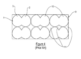
- the two layers 2, 3 are formed integrally with one another and cut from a large sheet of fabric 9.
- the integrally formed layers 2, 3 initially define a "butterfly" shape before the layers 2, 3 are folded and superimposed on one another to form the air-bag 1.
- a plurality of other identical "butterfly" shaped panels 10 are normally cut from the same large sheet of fabric 9 to be used to form other air-bags.
- the panels of fabric 10 are positioned to be as close as possible to one another on the large sheet of fabric 9 in order to minimise the amount of fabric that is wasted when the panels 10 are cut from the fabric 9. Whilst this manufacturing technique helps to reduce the amount of wasted fabric, there are still fabric sections 11 between the panels 10 that are wasted when the panels 10 are cut from the fabric 9.
- the present invention seeks to provide an improved air-bag and an improved method of manufacturing an air-bag.
- an air-bag for use in a vehicle, the air-bag comprising a first layer having a first edge and a second edge and a second layer having a third edge and a fourth edge, wherein the layers are offset rotationally relative to one another such that the first edge is at an angle A relative to the third edge and a first part of the second layer is superimposed on a first part of the first layer to define a reinforced part, and wherein a second part of the first layer is folded about a fold line that intersects the first edge and which is substantially at the angle A relative to the first edge so that a second part of the second layer is superimposed on the second part of the first layer to define a chamber therebetween, the layers being attached to one another at least partly around a periphery of the chamber so that the chamber may be inflated by gas provided by a source of gas.
- first and second edges of the first layer are substantially perpendicular to one another and the third and fourth edges of the second layer are substantially perpendicular to one another.
- the first and second layers are each substantially rectangular.
- a portion of the second layer is cut away along a cut edge which extends from the third edge to the fourth edge of the second layer at substantially the angle A relative to the fourth edge, and wherein the cut edge is substantially parallel to the fold line.
- the angle A is substantially 45o.
- first and second layers are attached to one another by a single seam which extends at least partly around the reinforced part (28) and the chamber.
- At least one of the first and second layers is provided with a vent aperture.
- At least one of the first and second layers is provided with an inlet aperture that enables gas to be injected into the chamber to inflate the chamber.
- a gas generator is coupled to the inlet aperture so that gas generated by the gas generator is injected through the inlet aperture and into the chamber, wherein at least part of the gas generator is positioned adjacent to the reinforced part.
- the superimposed first parts of the layers provide an interface to be mounted to at least one of a gas generator and a housing.
- a method of manufacturing an air-bag comprising providing a first layer having a first edge and a second edge providing a second layer having a third edge and a fourth edge; offsetting the layers rotationally relative to one another such that the first edge is at an angle A relative to the third edge; superimposing a first part of the second layer on a first part of the first layer to define a reinforced part; folding a second part of the first layer about a fold line that intersects the first edge and which is substantially at the angle A relative to the first edge and which is substantially at the angle A relative to the first edge; and superimposing a second part of the second layer on the second part of the first layer to define a chamber therebetween; and attaching the layers to one another at least partly around the periphery of the chamber so that the chamber may be inflated by gas provided by a source of gas.
- the steps of providing the first and second layers comprise cutting the first and second layers from the same fabric portion.
- the first and second layers are substantially rectangular.
- the method further comprises providing the second layer with a cut edge which extends from the third edge to the fourth edge at substantially the angle A relative to the fourth edge, and positioning the cut edge substantially parallel to the fold line.
- the step of attaching the layers to one another comprises stitching the layers to one another along a single seam which extends at least partly around the periphery of the reinforced part and the chamber.
- an air-bag of an embodiment of the invention comprises a first layer 12 and a second layer 13.
- Each of the layers 12, 13 is of a flexible woven fabric.
- the layers 12, 13 are discrete portions of fabric which are initially cut from a larger fabric portion 14, as shown in figure 7 .
- Further fabric layers 15 are preferably also cut from the same fabric portion 14 to form other air-bags.
- the layers 12, 13 are each rectangular or generally rectangular in shape, preferably with rounded corners. Each layer 12, 13 incorporates four straight edges which define the rectangular or generally rectangular shape.
- the rectangular or generally rectangular shape of the layers 12, 13 maximises the number of layers which may be cut from the section of fabric 14. This minimises the amount of fabric that is wasted during the manufacturing process since the rectangular or generally rectangular shape of the layers minimises the amount of fabric which is left after the layers have been cut from the fabric portion 14. The amount of wasted fabric is reduced significantly compared with a conventional "butterfly" air-bag such as the air-bag shown in figure 1 .
- An air-bag of an embodiment of the invention therefore has less fabric usage per air-bag kit than a conventional "butterfly" air-bag kit.
- the first layer 12 comprises a first edge 16 and a second edge 17 which are each perpendicular or generally perpendicular to one another.
- the first edge 16 is provided with a generally V-shaped notch 18 which extends from the first edge 16 into the body of the fabric of the first layer 12.
- the first layer 12 is provided with a first inlet aperture 19 which is positioned in a corner section of the first layer 12 adjacent the corner of the first layer 12, where the first edge 16 meets the second edge 17.
- the first layer 12 is provided with a vent aperture 20 which is positioned in a central portion of the body of fabric of the first layer 12.
- the first layer 12 is provided with further vent apertures.
- the first layer 12 is not provided with any vent apertures.
- the second layer 13 comprises a third edge 21 and a fourth edge 22 which are each perpendicular or generally perpendicular to one another.
- a portion of the second layer 13 is cut away along a cut edge 23 which extends from the third edge 21 to the fourth edge 22 of the second layer 13 at an angle A relative to the fourth edge 22.
- the angle A is 45o or substantially 45o.
- the second layer 13 comprises a generally V-shaped projection 24 which extends outwardly from the end of the cut edge 23 at the point at which the cut edge 23 meets the third edge 21 of the second layer 13.
- the second layer 13 is provided with a second inlet aperture 25 which is positioned adjacent the third edge 21 of the second layer 13.
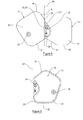
- the air-bag is assembled by offsetting the first and second layers 12, 13 rotationally relative to one another such that the first edge 16 is at the same or substantially the same angle A relative to the third edge 21 as the angle A of the cut edge 23 of the second layer 13.
- a first part 26 of the second layer 13 is superimposed on a first part 27 of the first layer 12 to define a reinforced part 28.
- One edge of the V-shaped projection 24 of the second layer 13 is aligned or is substantially aligned with the second edge 17 of the first layer 12.
- the first layer 12 is folded about a fold line 29 that that intersects the first edge 16 and which is at or is substantially at the angle A relative to the first edge 16 of the first layer 12 so that a second part 30 of the first layer 12 is superimposed on a second part 31 of the second layer 13 to define a chamber 32 therebetween, as shown in figure 9 .
- the first and second layers 12, 13 are attached to one another along a seam 33 which extends at least partly around the reinforced part 28 and the chamber 32.
- the seam 33 is preferably formed by stitching, but may alternatively be formed by another attachment formation, such as adhesive.
- the seam 33 is a single continuous seam which extends at least partly around the periphery of the reinforced part 28 and the chamber 32.
- Figure 10 of the accompanying drawings shows numbers 1-10 which indicate the order in which the stitching is carried out to produce the single continuous seam 33 which attaches the first and second layers 12, 13 to one another.
- the single continuous seam reduces the cost of manufacturing the air-bag since the single seam connects the layers 12, 13 to one another in a single manufacturing step.
- a source of gas preferably in the form of a gas generator is coupled to the inlets 19, 25.
- the inlets 19, 25 enable gas generated by the gas generator to be injected through the inlets 19, 25 and into the chamber 32.
- the chamber 32 is thus inflated by gas from the gas generator.
- At least part of the gas generator is positioned adjacent to the reinforced part 28.
- the superimposed first parts 26, 27 of the layers 12, 13 that form the reinforced part 28 provide an interface which enables the air-bag to be connected to at least one of a gas generator and a housing.
- the reinforced part 28, which is formed by parts of the first and second layers 12, 13 removes or reduces the need to provide additional reinforcing layers in order to attach a gas generator or a housing to the air-bag. This further reduces the cost and complexity of the method of manufacturing the air-bag.
- the shape of the inflated air-bag has a front portion that is thicker than a rear portion. This shape is produced as a result of the construction of the air-bag from the first and second layers 12, 13 as described above.
- the configuration of the panels 12, 13 enables the air-bag to take on this shape without requiring an additional wedge-shaped portion of the air-bag to be provided in addition to the two layers 12, 13. This further reduces the amount of fabric required to manufacture the air-bag.
- the difference in the side profile of the inflated air-bag of an embodiment of the invention is readily apparent when comparing the cross-sectional schematic diagram of figure 11 with the cross-sectional schematic diagram of a conventional air-bag as shown in figure 2 .
- the air-bag of the embodiments of the invention described above is a side air-bag.
- the air-bag is a different air-bag for use in a vehicle safety arrangement, such as a front or knee protection air-bag.
Abstract
Description
- The present invention relates to an air-bag, and in particular to an air-bag for use in a safety arrangement in a vehicle. The present invention also relates to a method of manufacturing an air-bag.
- It is known to provide a side air-bag within a vehicle in order to protect one side of an occupant of the vehicle in the event that the vehicle is involved in a crash situation. A conventional side air-bag has a generally oval side profile. An example of a conventional side air-
bag 1 is shown infigure 1 of the accompanying drawings. - The air-
bag 1 comprises twosuperimposed layers 2, 3 (only one of which is visible infigure 1 ) which are attached to one another around their periphery by astitching seam 4. One of thelayers region 5 which is positioned adjacent aninlet aperture 6. Theinlet aperture 6 is configured to be connected to a source of gas, such as a pyrotechnic gas generator. One of thelayers 2 is provided with avent aperture 8 to permit controlled venting of gas from within the inflated air-bag 1 during a crash situation. - The air-
bag 1 is configured to be inflated by gas to a thickness of approximately 100mm across aside protection face 7 of the air-bag 1. Once inflated, the cross-section of the air-bag 1 may be represented generally as a diamond shape, with the central portion being thicker than the rear and front portions of the air-bag 1, as shown infigures 2 and 3 . - Referring now to
figure 4 of the accompanying drawings, at an initial stage of a method of manufacturing the air-bag 1 the twolayers fabric 9. The integrally formedlayers layers bag 1. A plurality of other identical "butterfly" shapedpanels 10 are normally cut from the same large sheet offabric 9 to be used to form other air-bags. - The panels of
fabric 10 are positioned to be as close as possible to one another on the large sheet offabric 9 in order to minimise the amount of fabric that is wasted when thepanels 10 are cut from thefabric 9. Whilst this manufacturing technique helps to reduce the amount of wasted fabric, there are still fabric sections 11 between thepanels 10 that are wasted when thepanels 10 are cut from thefabric 9. - There is a need for an improved air-bag and an improved method of manufacturing an air-bag which minimises the amount of fabric that is wasted when the air-bag is manufactured.
- The present invention seeks to provide an improved air-bag and an improved method of manufacturing an air-bag.
- According to one aspect of the present invention, there is provided an air-bag for use in a vehicle, the air-bag comprising a first layer having a first edge and a second edge and a second layer having a third edge and a fourth edge, wherein the layers are offset rotationally relative to one another such that the first edge is at an angle A relative to the third edge and a first part of the second layer is superimposed on a first part of the first layer to define a reinforced part, and wherein a second part of the first layer is folded about a fold line that intersects the first edge and which is substantially at the angle A relative to the first edge so that a second part of the second layer is superimposed on the second part of the first layer to define a chamber therebetween, the layers being attached to one another at least partly around a periphery of the chamber so that the chamber may be inflated by gas provided by a source of gas.
- Preferably, the first and second edges of the first layer are substantially perpendicular to one another and the third and fourth edges of the second layer are substantially perpendicular to one another.
- Conveniently, the first and second layers are each substantially rectangular.
- Advantageously, a portion of the second layer is cut away along a cut edge which extends from the third edge to the fourth edge of the second layer at substantially the angle A relative to the fourth edge, and wherein the cut edge is substantially parallel to the fold line.
- Preferably, the angle A is substantially 45º.
- Conveniently, the first and second layers are attached to one another by a single seam which extends at least partly around the reinforced part (28) and the chamber.
- Advantageously, at least one of the first and second layers is provided with a vent aperture.
- Preferably, at least one of the first and second layers is provided with an inlet aperture that enables gas to be injected into the chamber to inflate the chamber.
- Conveniently, a gas generator is coupled to the inlet aperture so that gas generated by the gas generator is injected through the inlet aperture and into the chamber, wherein at least part of the gas generator is positioned adjacent to the reinforced part.
- Advantageously, the superimposed first parts of the layers provide an interface to be mounted to at least one of a gas generator and a housing.
- According to another aspect of the present invention, there is provided a method of manufacturing an air-bag, the method comprising providing a first layer having a first edge and a second edge providing a second layer having a third edge and a fourth edge; offsetting the layers rotationally relative to one another such that the first edge is at an angle A relative to the third edge; superimposing a first part of the second layer on a first part of the first layer to define a reinforced part; folding a second part of the first layer about a fold line that intersects the first edge and which is substantially at the angle A relative to the first edge and which is substantially at the angle A relative to the first edge; and superimposing a second part of the second layer on the second part of the first layer to define a chamber therebetween; and attaching the layers to one another at least partly around the periphery of the chamber so that the chamber may be inflated by gas provided by a source of gas.
- Preferably, the steps of providing the first and second layers comprise cutting the first and second layers from the same fabric portion.
- Conveniently, the first and second layers are substantially rectangular.
- Advantageously, the method further comprises providing the second layer with a cut edge which extends from the third edge to the fourth edge at substantially the angle A relative to the fourth edge, and positioning the cut edge substantially parallel to the fold line.
- Preferably, the step of attaching the layers to one another comprises stitching the layers to one another along a single seam which extends at least partly around the periphery of the reinforced part and the chamber.
- So that the present invention may be more readily understood, embodiments of the present invention will now be described, by way of example, with reference to the accompanying drawings, in which:
-
Figure 1 is a diagram showing a conventional side air-bag, -
Figure 2 is a diagrammatic side view of the air-bag offigure 1 when the air-bag is inflated, -
Figure 3 is a schematic diagram of the cross-section of the air-bag offigure 1 when the air-bag is inflated, -
Figure 4 is a diagram showing a large sheet of fabric during an initial step of manufacturing the air-bag offigure 1 , -
Figure 5 is a diagram showing a first layer of an air-bag of an embodiment of the invention, -
Figure 6 is a diagram showing a second layer of an air-bag of an embodiment of the invention, -
Figure 7 is a diagram showing a sheet of fabric during an initial step of manufacturing an air-bag of an embodiment of the invention, -
Figure 8 is a diagram showing the layers of the air-bag offigures 3 and4 being attached to one another during an intermediate manufacturing step of an embodiment of the invention, -
Figure 9 is a diagram showing an air-bag of an embodiment of the invention with the layers of the air-bag attached to one another, -
Figure 10 is a schematic diagram illustrating the order of stitching for a seam which attaches the layers of an air-bag to one another in an embodiment of the invention, -
Figure 11 is a diagram showing a side view of an air-bag of an embodiment of the invention when the air-bag is inflated, and -
Figure 12 is a schematic diagram of the cross-section of the air-bag offigure 10 when the air-bag is inflated. - Referring now to
figures 5 and 6 of the accompanying drawings, an air-bag of an embodiment of the invention comprises afirst layer 12 and asecond layer 13. Each of thelayers layers larger fabric portion 14, as shown infigure 7 .Further fabric layers 15 are preferably also cut from thesame fabric portion 14 to form other air-bags. - The
layers layer layers fabric 14. This minimises the amount of fabric that is wasted during the manufacturing process since the rectangular or generally rectangular shape of the layers minimises the amount of fabric which is left after the layers have been cut from thefabric portion 14. The amount of wasted fabric is reduced significantly compared with a conventional "butterfly" air-bag such as the air-bag shown infigure 1 . An air-bag of an embodiment of the invention therefore has less fabric usage per air-bag kit than a conventional "butterfly" air-bag kit. - The
first layer 12 comprises afirst edge 16 and asecond edge 17 which are each perpendicular or generally perpendicular to one another. Thefirst edge 16 is provided with a generally V-shaped notch 18 which extends from thefirst edge 16 into the body of the fabric of thefirst layer 12. - The
first layer 12 is provided with afirst inlet aperture 19 which is positioned in a corner section of thefirst layer 12 adjacent the corner of thefirst layer 12, where thefirst edge 16 meets thesecond edge 17. - The
first layer 12 is provided with avent aperture 20 which is positioned in a central portion of the body of fabric of thefirst layer 12. In further embodiments, thefirst layer 12 is provided with further vent apertures. In other embodiments, thefirst layer 12 is not provided with any vent apertures. - The
second layer 13 comprises athird edge 21 and afourth edge 22 which are each perpendicular or generally perpendicular to one another. - A portion of the
second layer 13 is cut away along acut edge 23 which extends from thethird edge 21 to thefourth edge 22 of thesecond layer 13 at an angle A relative to thefourth edge 22. In one embodiment, the angle A is 45º or substantially 45º. Thesecond layer 13 comprises a generally V-shapedprojection 24 which extends outwardly from the end of thecut edge 23 at the point at which thecut edge 23 meets thethird edge 21 of thesecond layer 13. - The
second layer 13 is provided with asecond inlet aperture 25 which is positioned adjacent thethird edge 21 of thesecond layer 13. - Referring now to
figure 8 of the accompanying drawings, the air-bag is assembled by offsetting the first andsecond layers first edge 16 is at the same or substantially the same angle A relative to thethird edge 21 as the angle A of thecut edge 23 of thesecond layer 13. Afirst part 26 of thesecond layer 13 is superimposed on afirst part 27 of thefirst layer 12 to define a reinforcedpart 28. When thefirst parts second layers second inlet apertures second layers - One edge of the V-shaped
projection 24 of thesecond layer 13 is aligned or is substantially aligned with thesecond edge 17 of thefirst layer 12. - The
first layer 12 is folded about afold line 29 that that intersects thefirst edge 16 and which is at or is substantially at the angle A relative to thefirst edge 16 of thefirst layer 12 so that asecond part 30 of thefirst layer 12 is superimposed on asecond part 31 of thesecond layer 13 to define achamber 32 therebetween, as shown infigure 9 . - The first and
second layers seam 33 which extends at least partly around the reinforcedpart 28 and thechamber 32. Theseam 33 is preferably formed by stitching, but may alternatively be formed by another attachment formation, such as adhesive. In this embodiment, theseam 33 is a single continuous seam which extends at least partly around the periphery of the reinforcedpart 28 and thechamber 32. -
Figure 10 of the accompanying drawings shows numbers 1-10 which indicate the order in which the stitching is carried out to produce the singlecontinuous seam 33 which attaches the first andsecond layers layers - Once the
layers inlets inlets inlets chamber 32. Thechamber 32 is thus inflated by gas from the gas generator. - In this embodiment, at least part of the gas generator is positioned adjacent to the reinforced
part 28. The superimposedfirst parts layers part 28 provide an interface which enables the air-bag to be connected to at least one of a gas generator and a housing. The reinforcedpart 28, which is formed by parts of the first andsecond layers - When the air-bag of an embodiment of the invention is inflated, the shape of the inflated air-bag has a front portion that is thicker than a rear portion. This shape is produced as a result of the construction of the air-bag from the first and
second layers panels layers figure 11 with the cross-sectional schematic diagram of a conventional air-bag as shown infigure 2 . - The air-bag of the embodiments of the invention described above is a side air-bag. However, in other embodiments, the air-bag is a different air-bag for use in a vehicle safety arrangement, such as a front or knee protection air-bag.
- When used in this specification and the claims, the term "comprises" and "comprising" and variations thereof mean that specified features, steps or integers and included. The terms are not to be interpreted to exclude the presence of other features, steps or compounds.
Claims (15)
- An air-bag for use in a vehicle, the air-bag comprising:a first layer (12) having a first edge (16) and a second edge (17); anda second layer (13) having a third edge (21) and a fourth edge (22), wherein the layers (12, 13) are offset rotationally relative to one another such that the first edge (16) is at an angle A relative to the third edge (21) and a first part (26) of the second layer (13) is superimposed on a first part (27) of the first layer (12) to define a reinforced part (28), and wherein a second part (30) of the first layer (12) is folded about a fold line (29) that intersects the first edge (16) and which is substantially at the angle A relative to the first edge (16) so that a second part (31) of the second layer (13) is superimposed on the second part (30) of the first layer (12) to define a chamber (32) therebetween, the layers (12, 13) being attached to one another at least partly around a periphery of the chamber (32) so that the chamber (32) may be inflated by gas provided by a source of gas.
- The air-bag of claim 1, wherein the first and second edges (16, 17) of the first layer (12) are substantially perpendicular to one another and the third and fourth edges (21, 22) of the second layer (13) are substantially perpendicular to one another.
- The air-bag of claim 1 or claim 2, wherein the first and second layers (12, 13) are each substantially rectangular.
- The air-bag of any one of the preceding claims, wherein a portion of the second layer (13) is cut away along a cut edge (23) which extends from the third edge (21) to the fourth edge (22) of the second layer (13) at substantially the angle A relative to the fourth edge (22), and wherein the cut edge (23) is substantially parallel to the fold line (29).
- The air-bag of any one of the preceding claims, wherein the angle A is substantially 45º.
- The air-bag of any one of the preceding claims, wherein the first and second layers (12, 13) are attached to one another by a single seam (33) which extends at least partly around the reinforced part (28) and the chamber (32).
- The air-bag of any one of the preceding claims, wherein at least one of the first and second layers (12, 13) is provided with a vent aperture (20).
- The air-bag of any one of the preceding claims, wherein at least one of the first and second layers (12, 13) is provided with an inlet aperture (19, 25) that enables gas to be injected into the chamber (32) to inflate the chamber (32).
- The air-bag of claim 8, wherein a gas generator is coupled to the inlet aperture (19, 25) so that gas generated by the gas generator is injected through the inlet aperture (19, 25) and into the chamber (32), wherein at least part of the gas generator is positioned adjacent to the reinforced part (28).
- The air-bag of any one of the preceding claims, wherein the superimposed first parts (26, 27) of the layers (12, 13) provide an interface to be mounted to at least one of a gas generator and a housing.
- A method of manufacturing an air-bag, the method comprising:providing a first layer (12) having a first edge (16) and a second edge (17);providing a second layer (13) having a third edge (21) and a fourth edge (22);offsetting the layers (12, 13) rotationally relative to one another such that the first edge (16) is at an angle A relative to the third edge (21);superimposing a first part (26) of the second layer (13) on a first part (27) of the first layer (12) to define a reinforced part (28);folding a second part (30) of the first layer (12) about a fold line (29) that intersects the first edge (16) and which is substantially at the angle A relative to the first edge (16) and superimposing a second part (31) of the second layer (13) on the second part (30) of the first layer (12) to define a chamber (32) therebetween; andattaching the layers (12, 13) to one another at least partly around the periphery of the chamber (32) so that the chamber (32) may be inflated by gas provided by a source of gas.
- The method of claim 11, wherein the steps of providing the first and second layers (12, 13) comprise cutting the first and second layers (12, 13) from the same fabric portion (14).
- The method of claim 11 or claim 12, wherein the first and second layers (12, 13) are substantially rectangular.
- The method of any one of claims 11 to 13, wherein the method further comprises providing the second layer (13) with a cut edge (23) which extends from the third edge to the fourth edge at substantially the angle A relative to the fourth edge, and positioning the cut edge (23) substantially parallel to the fold line (29).
- The method of any one of claims 11 to 14, wherein the step of attaching the layers (12, 13) to one another comprises stitching the layers (12, 13) to one another along a single seam (33) which extends at least partly around the periphery of the reinforced part (28) and the chamber (32).
Priority Applications (1)
| Application Number | Priority Date | Filing Date | Title |
|---|---|---|---|
| EP15160597.9A EP3072753B1 (en) | 2015-03-24 | 2015-03-24 | An air-bag |
Applications Claiming Priority (1)
| Application Number | Priority Date | Filing Date | Title |
|---|---|---|---|
| EP15160597.9A EP3072753B1 (en) | 2015-03-24 | 2015-03-24 | An air-bag |
Publications (2)
| Publication Number | Publication Date |
|---|---|
| EP3072753A1 true EP3072753A1 (en) | 2016-09-28 |
| EP3072753B1 EP3072753B1 (en) | 2018-10-24 |
Family
ID=52706070
Family Applications (1)
| Application Number | Title | Priority Date | Filing Date |
|---|---|---|---|
| EP15160597.9A Active EP3072753B1 (en) | 2015-03-24 | 2015-03-24 | An air-bag |
Country Status (1)
| Country | Link |
|---|---|
| EP (1) | EP3072753B1 (en) |
Citations (2)
| Publication number | Priority date | Publication date | Assignee | Title |
|---|---|---|---|---|
| EP1574404A2 (en) * | 2004-03-09 | 2005-09-14 | Milliken & Company | Airbag structure |
| US20080084053A1 (en) * | 2006-10-06 | 2008-04-10 | Benoit Bouquier | Airbags formed with efficient use of materials and methods of forming such airbags |
-
2015
- 2015-03-24 EP EP15160597.9A patent/EP3072753B1/en active Active
Patent Citations (2)
| Publication number | Priority date | Publication date | Assignee | Title |
|---|---|---|---|---|
| EP1574404A2 (en) * | 2004-03-09 | 2005-09-14 | Milliken & Company | Airbag structure |
| US20080084053A1 (en) * | 2006-10-06 | 2008-04-10 | Benoit Bouquier | Airbags formed with efficient use of materials and methods of forming such airbags |
Also Published As
| Publication number | Publication date |
|---|---|
| EP3072753B1 (en) | 2018-10-24 |
Similar Documents
| Publication | Publication Date | Title |
|---|---|---|
| US8678429B2 (en) | Occupant protection device | |
| JP5419477B2 (en) | Side airbag and side airbag device | |
| US20090020987A1 (en) | Multi-chambered side airbag | |
| WO2005000639A1 (en) | An air-bag | |
| US8235415B2 (en) | Textile gas guides for use with inflatable cushions | |
| US10974684B2 (en) | Multi-chambered driver-side airbag assemblies | |
| US20120038136A1 (en) | Airbag for a vehicle occupant restraint system and method for producing a vehicle occupant restraint system | |
| KR101198951B1 (en) | Airbag having vent hole | |
| US10384635B2 (en) | Front airbag | |
| EP3072753B1 (en) | An air-bag | |
| EP2868535B1 (en) | An airbag assembly | |
| US7303208B2 (en) | Air-bag | |
| JP2008001362A (en) | Airbag and method for manufacturing airbag | |
| EP1519858B1 (en) | An air-bag | |
| US11414037B2 (en) | Airbag for a vehicle occupant restraint system | |
| US11433849B2 (en) | Knee airbag module and method for packing a knee airbag into a housing | |
| WO2016035457A1 (en) | Air bag for front passanger's seat, and air bag device with same | |
| JP5278274B2 (en) | Airbag | |
| EP3176041B1 (en) | An inflatable airbag for a motor vehicle safety device | |
| JP6465610B2 (en) | Airbag | |
| US20190381967A1 (en) | Front airbag | |
| EP2520470B1 (en) | A pedestrian airbag | |
| EP2769886B1 (en) | An inflatable airbag for a motor vehicle safety device | |
| EP3388290B1 (en) | Method of manufacturing an airbag provided with a gas guide | |
| EP1602533A1 (en) | Airbag apparatus and method of manufacturing vehicle's airbag |
Legal Events
| Date | Code | Title | Description |
|---|---|---|---|
| PUAI | Public reference made under article 153(3) epc to a published international application that has entered the european phase |
Free format text: ORIGINAL CODE: 0009012 |
|
| AK | Designated contracting states |
Kind code of ref document: A1 Designated state(s): AL AT BE BG CH CY CZ DE DK EE ES FI FR GB GR HR HU IE IS IT LI LT LU LV MC MK MT NL NO PL PT RO RS SE SI SK SM TR |
|
| AX | Request for extension of the european patent |
Extension state: BA ME |
|
| STAA | Information on the status of an ep patent application or granted ep patent |
Free format text: STATUS: REQUEST FOR EXAMINATION WAS MADE |
|
| 17P | Request for examination filed |
Effective date: 20170328 |
|
| RBV | Designated contracting states (corrected) |
Designated state(s): AL AT BE BG CH CY CZ DE DK EE ES FI FR GB GR HR HU IE IS IT LI LT LU LV MC MK MT NL NO PL PT RO RS SE SI SK SM TR |
|
| GRAP | Despatch of communication of intention to grant a patent |
Free format text: ORIGINAL CODE: EPIDOSNIGR1 |
|
| STAA | Information on the status of an ep patent application or granted ep patent |
Free format text: STATUS: GRANT OF PATENT IS INTENDED |
|
| INTG | Intention to grant announced |
Effective date: 20180507 |
|
| GRAS | Grant fee paid |
Free format text: ORIGINAL CODE: EPIDOSNIGR3 |
|
| GRAA | (expected) grant |
Free format text: ORIGINAL CODE: 0009210 |
|
| STAA | Information on the status of an ep patent application or granted ep patent |
Free format text: STATUS: THE PATENT HAS BEEN GRANTED |
|
| AK | Designated contracting states |
Kind code of ref document: B1 Designated state(s): AL AT BE BG CH CY CZ DE DK EE ES FI FR GB GR HR HU IE IS IT LI LT LU LV MC MK MT NL NO PL PT RO RS SE SI SK SM TR |
|
| REG | Reference to a national code |
Ref country code: CH Ref legal event code: EP |
|
| REG | Reference to a national code |
Ref country code: IE Ref legal event code: FG4D |
|
| REG | Reference to a national code |
Ref country code: AT Ref legal event code: REF Ref document number: 1056294 Country of ref document: AT Kind code of ref document: T Effective date: 20181115 |
|
| REG | Reference to a national code |
Ref country code: DE Ref legal event code: R096 Ref document number: 602015018539 Country of ref document: DE |
|
| REG | Reference to a national code |
Ref country code: NL Ref legal event code: MP Effective date: 20181024 |
|
| REG | Reference to a national code |
Ref country code: LT Ref legal event code: MG4D |
|
| REG | Reference to a national code |
Ref country code: AT Ref legal event code: MK05 Ref document number: 1056294 Country of ref document: AT Kind code of ref document: T Effective date: 20181024 |
|
| PG25 | Lapsed in a contracting state [announced via postgrant information from national office to epo] |
Ref country code: NL Free format text: LAPSE BECAUSE OF FAILURE TO SUBMIT A TRANSLATION OF THE DESCRIPTION OR TO PAY THE FEE WITHIN THE PRESCRIBED TIME-LIMIT Effective date: 20181024 |
|
| PG25 | Lapsed in a contracting state [announced via postgrant information from national office to epo] |
Ref country code: PL Free format text: LAPSE BECAUSE OF FAILURE TO SUBMIT A TRANSLATION OF THE DESCRIPTION OR TO PAY THE FEE WITHIN THE PRESCRIBED TIME-LIMIT Effective date: 20181024 Ref country code: HR Free format text: LAPSE BECAUSE OF FAILURE TO SUBMIT A TRANSLATION OF THE DESCRIPTION OR TO PAY THE FEE WITHIN THE PRESCRIBED TIME-LIMIT Effective date: 20181024 Ref country code: LT Free format text: LAPSE BECAUSE OF FAILURE TO SUBMIT A TRANSLATION OF THE DESCRIPTION OR TO PAY THE FEE WITHIN THE PRESCRIBED TIME-LIMIT Effective date: 20181024 Ref country code: BG Free format text: LAPSE BECAUSE OF FAILURE TO SUBMIT A TRANSLATION OF THE DESCRIPTION OR TO PAY THE FEE WITHIN THE PRESCRIBED TIME-LIMIT Effective date: 20190124 Ref country code: AT Free format text: LAPSE BECAUSE OF FAILURE TO SUBMIT A TRANSLATION OF THE DESCRIPTION OR TO PAY THE FEE WITHIN THE PRESCRIBED TIME-LIMIT Effective date: 20181024 Ref country code: IS Free format text: LAPSE BECAUSE OF FAILURE TO SUBMIT A TRANSLATION OF THE DESCRIPTION OR TO PAY THE FEE WITHIN THE PRESCRIBED TIME-LIMIT Effective date: 20190224 Ref country code: NO Free format text: LAPSE BECAUSE OF FAILURE TO SUBMIT A TRANSLATION OF THE DESCRIPTION OR TO PAY THE FEE WITHIN THE PRESCRIBED TIME-LIMIT Effective date: 20190124 Ref country code: ES Free format text: LAPSE BECAUSE OF FAILURE TO SUBMIT A TRANSLATION OF THE DESCRIPTION OR TO PAY THE FEE WITHIN THE PRESCRIBED TIME-LIMIT Effective date: 20181024 Ref country code: FI Free format text: LAPSE BECAUSE OF FAILURE TO SUBMIT A TRANSLATION OF THE DESCRIPTION OR TO PAY THE FEE WITHIN THE PRESCRIBED TIME-LIMIT Effective date: 20181024 Ref country code: LV Free format text: LAPSE BECAUSE OF FAILURE TO SUBMIT A TRANSLATION OF THE DESCRIPTION OR TO PAY THE FEE WITHIN THE PRESCRIBED TIME-LIMIT Effective date: 20181024 |
|
| PGFP | Annual fee paid to national office [announced via postgrant information from national office to epo] |
Ref country code: GB Payment date: 20190329 Year of fee payment: 5 |
|
| PG25 | Lapsed in a contracting state [announced via postgrant information from national office to epo] |
Ref country code: AL Free format text: LAPSE BECAUSE OF FAILURE TO SUBMIT A TRANSLATION OF THE DESCRIPTION OR TO PAY THE FEE WITHIN THE PRESCRIBED TIME-LIMIT Effective date: 20181024 Ref country code: SE Free format text: LAPSE BECAUSE OF FAILURE TO SUBMIT A TRANSLATION OF THE DESCRIPTION OR TO PAY THE FEE WITHIN THE PRESCRIBED TIME-LIMIT Effective date: 20181024 Ref country code: RS Free format text: LAPSE BECAUSE OF FAILURE TO SUBMIT A TRANSLATION OF THE DESCRIPTION OR TO PAY THE FEE WITHIN THE PRESCRIBED TIME-LIMIT Effective date: 20181024 Ref country code: GR Free format text: LAPSE BECAUSE OF FAILURE TO SUBMIT A TRANSLATION OF THE DESCRIPTION OR TO PAY THE FEE WITHIN THE PRESCRIBED TIME-LIMIT Effective date: 20190125 Ref country code: PT Free format text: LAPSE BECAUSE OF FAILURE TO SUBMIT A TRANSLATION OF THE DESCRIPTION OR TO PAY THE FEE WITHIN THE PRESCRIBED TIME-LIMIT Effective date: 20190224 |
|
| REG | Reference to a national code |
Ref country code: DE Ref legal event code: R097 Ref document number: 602015018539 Country of ref document: DE |
|
| PG25 | Lapsed in a contracting state [announced via postgrant information from national office to epo] |
Ref country code: DK Free format text: LAPSE BECAUSE OF FAILURE TO SUBMIT A TRANSLATION OF THE DESCRIPTION OR TO PAY THE FEE WITHIN THE PRESCRIBED TIME-LIMIT Effective date: 20181024 Ref country code: IT Free format text: LAPSE BECAUSE OF FAILURE TO SUBMIT A TRANSLATION OF THE DESCRIPTION OR TO PAY THE FEE WITHIN THE PRESCRIBED TIME-LIMIT Effective date: 20181024 Ref country code: CZ Free format text: LAPSE BECAUSE OF FAILURE TO SUBMIT A TRANSLATION OF THE DESCRIPTION OR TO PAY THE FEE WITHIN THE PRESCRIBED TIME-LIMIT Effective date: 20181024 |
|
| PG25 | Lapsed in a contracting state [announced via postgrant information from national office to epo] |
Ref country code: RO Free format text: LAPSE BECAUSE OF FAILURE TO SUBMIT A TRANSLATION OF THE DESCRIPTION OR TO PAY THE FEE WITHIN THE PRESCRIBED TIME-LIMIT Effective date: 20181024 Ref country code: EE Free format text: LAPSE BECAUSE OF FAILURE TO SUBMIT A TRANSLATION OF THE DESCRIPTION OR TO PAY THE FEE WITHIN THE PRESCRIBED TIME-LIMIT Effective date: 20181024 Ref country code: SM Free format text: LAPSE BECAUSE OF FAILURE TO SUBMIT A TRANSLATION OF THE DESCRIPTION OR TO PAY THE FEE WITHIN THE PRESCRIBED TIME-LIMIT Effective date: 20181024 Ref country code: SK Free format text: LAPSE BECAUSE OF FAILURE TO SUBMIT A TRANSLATION OF THE DESCRIPTION OR TO PAY THE FEE WITHIN THE PRESCRIBED TIME-LIMIT Effective date: 20181024 |
|
| PLBE | No opposition filed within time limit |
Free format text: ORIGINAL CODE: 0009261 |
|
| STAA | Information on the status of an ep patent application or granted ep patent |
Free format text: STATUS: NO OPPOSITION FILED WITHIN TIME LIMIT |
|
| 26N | No opposition filed |
Effective date: 20190725 |
|
| PG25 | Lapsed in a contracting state [announced via postgrant information from national office to epo] |
Ref country code: MC Free format text: LAPSE BECAUSE OF FAILURE TO SUBMIT A TRANSLATION OF THE DESCRIPTION OR TO PAY THE FEE WITHIN THE PRESCRIBED TIME-LIMIT Effective date: 20181024 Ref country code: SI Free format text: LAPSE BECAUSE OF FAILURE TO SUBMIT A TRANSLATION OF THE DESCRIPTION OR TO PAY THE FEE WITHIN THE PRESCRIBED TIME-LIMIT Effective date: 20181024 |
|
| REG | Reference to a national code |
Ref country code: CH Ref legal event code: PL |
|
| PG25 | Lapsed in a contracting state [announced via postgrant information from national office to epo] |
Ref country code: LU Free format text: LAPSE BECAUSE OF NON-PAYMENT OF DUE FEES Effective date: 20190324 |
|
| REG | Reference to a national code |
Ref country code: BE Ref legal event code: MM Effective date: 20190331 |
|
| PG25 | Lapsed in a contracting state [announced via postgrant information from national office to epo] |
Ref country code: CH Free format text: LAPSE BECAUSE OF NON-PAYMENT OF DUE FEES Effective date: 20190331 Ref country code: IE Free format text: LAPSE BECAUSE OF NON-PAYMENT OF DUE FEES Effective date: 20190324 Ref country code: LI Free format text: LAPSE BECAUSE OF NON-PAYMENT OF DUE FEES Effective date: 20190331 |
|
| PG25 | Lapsed in a contracting state [announced via postgrant information from national office to epo] |
Ref country code: BE Free format text: LAPSE BECAUSE OF NON-PAYMENT OF DUE FEES Effective date: 20190331 |
|
| PG25 | Lapsed in a contracting state [announced via postgrant information from national office to epo] |
Ref country code: TR Free format text: LAPSE BECAUSE OF FAILURE TO SUBMIT A TRANSLATION OF THE DESCRIPTION OR TO PAY THE FEE WITHIN THE PRESCRIBED TIME-LIMIT Effective date: 20181024 |
|
| PG25 | Lapsed in a contracting state [announced via postgrant information from national office to epo] |
Ref country code: MT Free format text: LAPSE BECAUSE OF NON-PAYMENT OF DUE FEES Effective date: 20190324 |
|
| GBPC | Gb: european patent ceased through non-payment of renewal fee |
Effective date: 20200324 |
|
| PG25 | Lapsed in a contracting state [announced via postgrant information from national office to epo] |
Ref country code: GB Free format text: LAPSE BECAUSE OF NON-PAYMENT OF DUE FEES Effective date: 20200324 |
|
| PG25 | Lapsed in a contracting state [announced via postgrant information from national office to epo] |
Ref country code: CY Free format text: LAPSE BECAUSE OF FAILURE TO SUBMIT A TRANSLATION OF THE DESCRIPTION OR TO PAY THE FEE WITHIN THE PRESCRIBED TIME-LIMIT Effective date: 20181024 |
|
| PG25 | Lapsed in a contracting state [announced via postgrant information from national office to epo] |
Ref country code: HU Free format text: LAPSE BECAUSE OF FAILURE TO SUBMIT A TRANSLATION OF THE DESCRIPTION OR TO PAY THE FEE WITHIN THE PRESCRIBED TIME-LIMIT; INVALID AB INITIO Effective date: 20150324 |
|
| PG25 | Lapsed in a contracting state [announced via postgrant information from national office to epo] |
Ref country code: MK Free format text: LAPSE BECAUSE OF FAILURE TO SUBMIT A TRANSLATION OF THE DESCRIPTION OR TO PAY THE FEE WITHIN THE PRESCRIBED TIME-LIMIT Effective date: 20181024 |
|
| PGFP | Annual fee paid to national office [announced via postgrant information from national office to epo] |
Ref country code: FR Payment date: 20230322 Year of fee payment: 9 |
|
| PGFP | Annual fee paid to national office [announced via postgrant information from national office to epo] |
Ref country code: DE Payment date: 20230320 Year of fee payment: 9 |
|
| P01 | Opt-out of the competence of the unified patent court (upc) registered |
Effective date: 20230507 |