EP3072748A1 - Protector, assembly of wire with protector, and assembling method therefor - Google Patents
Protector, assembly of wire with protector, and assembling method therefor Download PDFInfo
- Publication number
- EP3072748A1 EP3072748A1 EP16000619.3A EP16000619A EP3072748A1 EP 3072748 A1 EP3072748 A1 EP 3072748A1 EP 16000619 A EP16000619 A EP 16000619A EP 3072748 A1 EP3072748 A1 EP 3072748A1
- Authority
- EP
- European Patent Office
- Prior art keywords
- wire
- protector
- fixing piece
- wire fixing
- out port
- Prior art date
- Legal status (The legal status is an assumption and is not a legal conclusion. Google has not performed a legal analysis and makes no representation as to the accuracy of the status listed.)
- Withdrawn
Links
Images






Classifications
-
- B—PERFORMING OPERATIONS; TRANSPORTING
- B60—VEHICLES IN GENERAL
- B60R—VEHICLES, VEHICLE FITTINGS, OR VEHICLE PARTS, NOT OTHERWISE PROVIDED FOR
- B60R16/00—Electric or fluid circuits specially adapted for vehicles and not otherwise provided for; Arrangement of elements of electric or fluid circuits specially adapted for vehicles and not otherwise provided for
- B60R16/02—Electric or fluid circuits specially adapted for vehicles and not otherwise provided for; Arrangement of elements of electric or fluid circuits specially adapted for vehicles and not otherwise provided for electric constitutive elements
- B60R16/0207—Wire harnesses
- B60R16/0215—Protecting, fastening and routing means therefor
-
- H—ELECTRICITY
- H01—ELECTRIC ELEMENTS
- H01B—CABLES; CONDUCTORS; INSULATORS; SELECTION OF MATERIALS FOR THEIR CONDUCTIVE, INSULATING OR DIELECTRIC PROPERTIES
- H01B7/00—Insulated conductors or cables characterised by their form
- H01B7/0045—Cable-harnesses
-
- H—ELECTRICITY
- H02—GENERATION; CONVERSION OR DISTRIBUTION OF ELECTRIC POWER
- H02G—INSTALLATION OF ELECTRIC CABLES OR LINES, OR OF COMBINED OPTICAL AND ELECTRIC CABLES OR LINES
- H02G3/00—Installations of electric cables or lines or protective tubing therefor in or on buildings, equivalent structures or vehicles
- H02G3/02—Details
- H02G3/04—Protective tubing or conduits, e.g. cable ladders or cable troughs
- H02G3/0406—Details thereof
-
- H—ELECTRICITY
- H02—GENERATION; CONVERSION OR DISTRIBUTION OF ELECTRIC POWER
- H02G—INSTALLATION OF ELECTRIC CABLES OR LINES, OR OF COMBINED OPTICAL AND ELECTRIC CABLES OR LINES
- H02G3/00—Installations of electric cables or lines or protective tubing therefor in or on buildings, equivalent structures or vehicles
- H02G3/02—Details
- H02G3/04—Protective tubing or conduits, e.g. cable ladders or cable troughs
- H02G3/0462—Tubings, i.e. having a closed section
- H02G3/0487—Tubings, i.e. having a closed section with a non-circular cross-section
-
- H—ELECTRICITY
- H02—GENERATION; CONVERSION OR DISTRIBUTION OF ELECTRIC POWER
- H02G—INSTALLATION OF ELECTRIC CABLES OR LINES, OR OF COMBINED OPTICAL AND ELECTRIC CABLES OR LINES
- H02G3/00—Installations of electric cables or lines or protective tubing therefor in or on buildings, equivalent structures or vehicles
- H02G3/02—Details
- H02G3/08—Distribution boxes; Connection or junction boxes
- H02G3/14—Fastening of cover or lid to box
-
- H—ELECTRICITY
- H02—GENERATION; CONVERSION OR DISTRIBUTION OF ELECTRIC POWER
- H02G—INSTALLATION OF ELECTRIC CABLES OR LINES, OR OF COMBINED OPTICAL AND ELECTRIC CABLES OR LINES
- H02G3/00—Installations of electric cables or lines or protective tubing therefor in or on buildings, equivalent structures or vehicles
- H02G3/02—Details
- H02G3/08—Distribution boxes; Connection or junction boxes
- H02G3/18—Distribution boxes; Connection or junction boxes providing line outlets
-
- H—ELECTRICITY
- H02—GENERATION; CONVERSION OR DISTRIBUTION OF ELECTRIC POWER
- H02G—INSTALLATION OF ELECTRIC CABLES OR LINES, OR OF COMBINED OPTICAL AND ELECTRIC CABLES OR LINES
- H02G3/00—Installations of electric cables or lines or protective tubing therefor in or on buildings, equivalent structures or vehicles
- H02G3/26—Installations of cables, lines, or separate protective tubing therefor directly on or in walls, ceilings, or floors
-
- H—ELECTRICITY
- H02—GENERATION; CONVERSION OR DISTRIBUTION OF ELECTRIC POWER
- H02G—INSTALLATION OF ELECTRIC CABLES OR LINES, OR OF COMBINED OPTICAL AND ELECTRIC CABLES OR LINES
- H02G3/00—Installations of electric cables or lines or protective tubing therefor in or on buildings, equivalent structures or vehicles
- H02G3/30—Installations of cables or lines on walls, floors or ceilings
- H02G3/32—Installations of cables or lines on walls, floors or ceilings using mounting clamps
Definitions
- the present invention relates to a protector for protecting a wire, to an assembly of a wire and protector and to an assembling method therefor.
- Japanese Unexamined Patent Publication No. 2012-85478 discloses a configuration for forming tape winding pieces on opposite ends of a protector.
- a wiring harness is fixed to the protector by winding an adhesive tape on the wiring harness and the tape winding pieces.
- Japanese Unexamined Patent Publication No. 2012-100460 discloses a technology for inserting a base end part of a branch line into a slit of a rubber member and fitting this rubber member into a branch line accommodating portion of a protector to fix the rubber member.
- the adhesive tape winding operation needs to be performed with the wiring harness accommodated in a main body of the protector and the tape winding pieces are integrally formed to the main body of the protector.
- the tape winding operation is difficult depending on extending directions of the tape winding pieces.
- the present invention aims to enable a wire to be easily and reliably positioned and fixed in a protector.
- a protector which includes a wire accommodating portion formed with an accommodation space capable of at least partly accommodating at least one wire and a wire draw-out port for drawing out the wire accommodated in the accommodation space to outside, and at least one wire fixing piece formed separately from the wire accommodating portion and unitable with the wire draw-out port in a state fixed at a certain (predetermined or predeterminable) position in an extending direction of the wire by at least one binding member.
- the wire fixing piece can be fixed to the wire accommodating portion after the wire is fixed to the wire fixing piece by the binding member.
- the wire can be easily and reliably positioned and fixed in or to the protector.
- the wire fixing piece is unitable with or fixable to the wire accommodating portion at a position where at least a part of the binding member for binding and fixing the wire and the wire fixing piece is arranged in the wire accommodating portion.
- the binding member can be protected since at least the part of the binding member is arranged in the wire accommodating portion.
- the wire accommodating portion includes a protector main body portion with a base plate portion (particularly a bottom plate portion) and one or more, particularly a pair of side wall portions standing from (particularly substantially opposite sides of) the base (bottom) plate portion, and a lid portion to be mounted on the protector main body portion to at least partly close an opening of the protector main body, particularly substantially facing the base (bottom) plate portion.
- the wire can be easily accommodated into the protector main body portion through the opening facing the bottom plate portion.
- the wire and at least the part of the binding member can be protected.
- the wire fixing piece includes a bound portion to be bound and fixed to the wire and a wide portion wider than the bound portion, at least one fixing projecting portion is formed on one of a side part of the wide portion and the wire accommodating portion and a wire fixing recess, in which the fixing projecting portion is arrangeable, is formed on the other.
- the wire fixing piece can be fixed to the wire accommodating portion particularly by arranging the fixing projecting portion formed on the one of the side part of the wide portion and the wire accommodating portion in the wire fixing recess formed on the other with the bound portion and the wire bound and fixed. At this time, it is sufficient to arrange the fixing projecting portion in the wire fixing recess formed on the side part of the wide portion wider than the bound portion, wherefore a fixing operation by this arranging operation can be easily performed.
- a plurality of the wire fixing pieces are provided, and the plurality of wire fixing pieces are unitable or fixable substantially side by side with the wire draw-out port.
- an operation of binding and fixing the wire can be easily performed and the wire can be more reliably fixed since the wire can be bound and fixed to each of the plurality of wire fixing pieces.
- an integrated wire fixing piece is further provided which is integrally formed to the wire draw-out port.
- the wire fixing piece is unitable with the wire draw-out port on a side adjacent to the integrated wire fixing piece.
- the operation of binding and fixing the wire can be easily performed and the wire can be more reliably fixed, since the wire can be bound and fixed to each of the integrated wire fixing piece and the wire fixing piece.
- an assembly of wire with protector which includes a protector according to the above aspect of a particular embodiment thereof, a wire and a binding member for binding and fixing the wire and the wire fixing piece, and the wire fixing piece at least partly is accommodated in the accommodation space in a state where the wire fixing piece is united with the wire draw-out port and the wire is drawn out to outside from the wire draw-out port.
- a method of assembling a wire with a protector i.e. producing an assembly of a wire with protector
- a method of assembling a wire with a protector comprising: binding and fixing at least one wire to at least one wire fixing piece of the protector; at least partly accommodating the wire fixing piece in an accommodation space of the protector thereby uniting the wire fixing piece with the wire draw-out port of the protector; and drawing out the wire to outside from the wire draw-out port.
- the wire fixing piece is united with the wire accommodating portion at a position where at least a part of the binding member for binding and fixing the wire and the wire fixing piece is arranged in the wire accommodating portion.
- the wire at least partly is enclosed by a protector main body portion with a base plate portion and one or more side wall portions standing from the base plate portion; and a lid portion is mounted on the protector main body portion to at least partly close an opening of the protector main body portion.
- the wire fixing piece includes a bound portion to be bound and fixed to the wire and a wide portion wider than the bound portion; and wherein at least one fixing projecting portion is formed on one of a side part of the wide portion and the wire accommodating portion and a wire fixing recess, in which the fixing projecting portion is arrangeable, is formed on the other.
- the method further comprises providing a plurality of the wire fixing pieces; and uniting the plurality of wire fixing pieces substantially side by side with the wire draw-out port.
- the method further comprises integrally or unitarily forming an integrated wire fixing piece to the wire draw-out port.
- the wire fixing piece is united with the wire draw-out port on a side adjacent to the integrated wire fixing piece.
- the wire fixing piece can be fixed to the wire accommodating portion after the wire is fixed to the wire fixing piece by the binding member.
- the wire can be easily and reliably positioned and fixed in the protector.
- FIG. 1 is a perspective view showing the wires with protector 10. Note that one end part of the protector 20 is shown, but the other end part is not shown in FIG. 1 and each of other figures.
- the one or more wires with protector 10 include the protector 20, one or more wires 12 and at least one binding member 18.
- the wire 12 particularly is such that an insulation coating is formed around a core which is a conductive wire.
- the wire 12 particularly can supply power and/or transmit a signal.
- the wires with protector 10 particularly include a plurality of wires 12.
- the plurality of wires 12 at least partly may be branched in parts accommodated in the protector 20 and/or outside the protector 20. If the plurality of wires 12 at least partly are branched in the parts accommodated in the protector 20, the protector 20 may have an opening for allowing the part(s) branched at an intermediate part in an extending direction of the protector 20 to be extended to outside.
- Connectors are mounted on (particularly end parts of) the plurality of wires 12.
- the respective connectors are or may be connected to various electrical components mounted in a vehicle with the wires with protector 10 assembled in the vehicle.
- the plurality of wires 12 are used as a wiring harness which is a wiring material in the vehicle.
- An optical fiber cable may be bundled together with the wires 12.
- the protector 20 at least partly accommodates substantially linearly bound parts of the plurality of wires 12.
- the protector 20 at least partly accommodates parts of (particularly the substantially linear parts of) the plurality of wires 12.
- the plurality of wires 12 are drawn out to outside through at least one wire draw-out port 23 on one end part of the protector 20.
- the other end part of the protector 20 may be configured similarly to the wire draw-out port 23 described here or may be so configured that a wire fixing piece is integrally or unitarily formed as before.
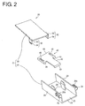
- FIG. 2 is an exploded perspective view showing the protector 20
- FIG. 3 is a plan view showing a protector main body portion 24
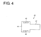
- FIG. 4 is a plan view showing a wire fixing piece 40
- FIG. 5 is a plan view showing a lid portion 30.
- the protector 20 includes at least one wire accommodating portion 22 and the at least one wire fixing piece 40.
- the wire accommodating portion 22 particularly substantially is formed into a tubular shape; here specifically into a rectangular or polygonal tubular shape.
- the wire accommodating portion 22 specifically is formed into a rectangular tube shape whose height is smaller than a width here, it is not essential.
- a (particularly substantially rectangular parallelepipedic) accommodation space capable of accommodating the wires 12 is formed in the wire accommodating portion 22.
- the wire draw-out ports 23 for drawing out the one or more wires 12 to outside are formed on substantially opposite end parts of the wire accommodating portion 22.
- the wire draw-out port 23 particularly is a rectangular or polygonal opening.
- the wire accommodating portion 22 includes the protector main body portion 24 and the at least one lid portion 30.
- the protector main body portion 24 particularly is a member molded of resin or the like and includes a bottom plate portion 25 (as a particular base plate portion) and one or more, particularly a pair of side wall portions 28.
- the bottom plate portion 25 particularly substantially is in the form of a long and narrow plate.
- the bottom plate portion 25 may be bent in a width and/or thickness direction thereof at an intermediate part in an extending direction thereof.
- the pair of side wall portions 28 are formed to stand toward one principal surface side of the bottom plate portion 25 from (particularly substantially opposite side parts of) the bottom plate portion 25. Note that although the pair of side wall portions 28 stand in a posture at an angle different from 0° or 180°, preferably substantially perpendicular to the bottom plate portion 25 here, the side wall portions 28 and the bottom plate portion 25 may be connected via curved parts.
- Intermediate parts of the wires 12 in the extending direction ED can be at least partly accommodated in a space substantially enclosed or defined by the bottom plate portion 25 and the one or more, particularly pair of side wall portions 28.
- One or more fixing projecting portions 26 are formed on (particularly an opening end part of) the bottom plate portion 25 particularly where the wire draw-out port 23 is formed. These fixing projecting portions 26 are described in detail later in connection with the wire fixing piece 40.
- one or more lock receiving portions 29 are provided on the one or more side wall portions 28, particularly on parts of outer surfaces of the pair of side wall portions 28 on a side substantially opposite to the bottom plate portion 25.
- the lock receiving portion 29 includes an opening 29h penetrating in a direction perpendicular to the bottom plate portion 25 and at least one lock piece 32 of the lid portion 30 to be described later is locked and fixed to the lock receiving portion 29 by being at least partly inserted into this opening 29h.
- the lid portion 30 particularly is a member molded of resin or the like and/or configured to be mountable on the protector main body portion 24 to at least partly close an opening facing the bottom plate portion 25.
- the lid portion 30 particularly substantially is in the form of a long and narrow piece similarly to the bottom plate portion 25 and/or configured to particularly substantially close the entire opening of the protector main body portion 24 on the side substantially opposite to the bottom plate portion 25.
- One or more lock pieces 32 are provided to project at one or more positions respectively corresponding to the above one or more lock receiving portions 29 particularly on substantially opposite side parts of the lid portion 30.
- the lock piece 32 particularly includes a plate-like portion 33 projecting from (particularly the side part of) the lid portion 30 substantially toward the protector main body portion 24 and at least one lock protrusion 34 projecting on (particularly an outer surface of a tip part of) the plate-like portion 33.
- the lock protrusion 34 particularly is formed into a shape whose height is gradually reduced toward a tip side of the lock piece 32.
- the wire draw-out port 23 on the end part of the wire accommodating portion 22 is surrounded on plural (e.g. four) sides by the protector main body portion 24 and the lid portion 30.
- the wire accommodating portion may be left open on the side opposite to the bottom plate portion.
- the wire fixing piece 40 particularly is a member molded of resin or the like separately from the above wire accommodating portion 22 and unitable with or connectable to the wire draw-out port 23 in a state fixed at a certain (predetermined or predeterminable) position in the extending direction ED of the wires 12 by the binding member 18.
- the wire fixing piece 40 substantially is in the form of a plate as a whole and particularly includes at least one bound portion 42 and at least one wide portion 44.
- the bound portion 42 particularly substantially is a plate-like part to be bound and fixed to the one or more wires 12.
- the bound portion 42 preferably has a width smaller than an outer diameter of a bundle of the plurality of wires 12. This enables a force of the binding member 18 for holding the one or more, particularly the plurality of wires 12 in a bundled state to effectively act and particularly the wires 12 to be more reliably fixed in the bundled state at the certain position when the binding member 18 is wound on or provided on or at least partly around the bundle of the wires 12 and the bound portion 42.
- At least one part (particularly an edge part) of the bound portion 42 is formed into at least one retaining portion 43 projecting toward one principal surface side of the bound portion 42.
- the binding member 18 is fixed (particularly wound) on a part of the bound portion 42 inwardly of the retaining portion 43. In this way, the binding member 18 is caught by the retaining portion 43, with the result that the fall-off of the binding member 18 from the bound portion 42 is suppressed.
- the wide portion 44 particularly is a substantially plate-like part integrally or unitarily formed to (particularly one end part of) the bound portion 42 to substantially spread or extend on the same plane.
- the wide portion 44 particularly is formed to be wider than the bound portion 42.
- the wide portion 44 is formed to have a width larger than the outer diameter of the bundle of the plurality of wires 12. This causes one or more opposite end parts of the wide portion 44 to protrude laterally outwardly from the bundle of the wires 12 with the bound portion 42 fixed to the bundle of the wires 12.
- the one or more fixing projecting portions 26 are formed on one of the wide portion 44 and/or the wire draw-out port 23 of the wire accommodating portion 22 and the wire fixing recesses 46 are formed on the other.
- the fixing projecting portions 26 particularly are formed on the protector main body portion 24 of the wire accommodating portion 22 and the wire fixing recesses 46 are formed on the wide portion 44.
- one or more, particularly a pair of fixing projecting portions 26 are formed on (particularly opposite side parts of an end part of) the bottom plate portion 25 of the protector main body portion 24 where the wire draw-out port 23 is formed.
- the one or more fixing projecting portions 26 particularly are in the form of flat plates extending substantially along an extending direction of the side wall portions 28. This enables the wire fixing piece 40 to be held in a constant posture as much as possible in a state where the fixing projecting portions 26 at least partly are inserted and fitted in wire fixing recesses 46.
- the fixing projecting portions 26 may be in the form of round bars or rectangular bars or any other suitable shape.
- a height of the fixing projecting portions 26 particularly is set to be substantially equal to or smaller (slightly smaller) than that of the side wall portions 28. This makes tip sides of the fixing projecting portions 26 difficult to come out of the wire fixing recesses 46 in a state where the fixing projecting portions 26 are inserted in the wire fixing recesses 46.
- the height of the fixing projecting portions 26 may be smaller than in the above example.
- the tip parts of the fixing projecting portions 26 particularly are formed to be gradually narrower and thinner toward the tip sides. This enables the fixing projecting portions 26 to be easily inserted into the wire fixing recesses 46.
- the tip parts of the fixing projecting portions 26 may be shaped to have the same dimensions as the remaining parts.
- opening parts of the wire fixing recesses 46 substantially facing the bottom plate portion 25 particularly may be shaped to be gradually wider toward the bound portion 25.
- the fixing projecting portions 26 particularly may be press-fitted into or engaged with the wire fixing recesses 46, thereby being retained.
- one or more lock projections for retaining and locking the wire fixing recesses 46 in a state where the fixing projecting portions 26 at least partly are inserted to the backs of the wire fixing recesses 46 particularly may be provided to project on the fixing projecting portions 26.
- the one or more, particularly the pair of fixing projecting portions 26 are provided at positions spaced apart from the side wall portion(s) 28.
- An interval between the pair of fixing projecting portions 26 particularly is set to be substantially equal to or larger than the outer diameter of the bundle of the wires 12. This enables the bundle of the wires 12 to be arranged particularly between the pair of fixing projecting portions 26.
- the wire fixing recesse(s) 46 particularly is/are formed at positions substantially corresponding to the (pair of) fixing projecting portion(s) 26 particularly on substantially opposite side parts of the wide portion 44.
- the wire fixing recesses 46 are formed into (particularly substantially rectangular) through holes.
- the wire fixing recesses 46 are preferably so shaped and dimensioned that the fixing projecting portions 26 are fitted thereinto as closely as possible.
- parts at outer side(s) of the wire fixing recess(es) 46 located on the side of the bottom plate portion 25 particularly is/are formed into protrusion(s) 48 particularly substantially projecting about the same distance as the retaining portion 43.
- the retaining portion 43 and the one or more, particularly the pair of protrusions 48 particularly are arranged in contact with the upper surface of the bottom plate portion 25.
- the wire fixing piece 40 is fixed at the certain (predetermined or predeterminable) position relative to the wire draw-out port 23.
- the positions of the pair of fixing projecting portions 26 particularly are so set that at least a part of the binding member 18 wound on the bound portion 42 and the wires 12 is arranged in the wire accommodating portion 22.
- the pair of fixing projecting portions 26 particularly are formed at positions where the pair of wire fixing recesses 46 are arranged in a state where an end part of the bound portion 42 substantially is arranged in alignment with an edge part of the wire draw-out port 23.
- the binding member 18 is a member for binding and fixing the wires 12 and the wire fixing piece 40.
- the binding member 18 particularly is configured by an adhesive tape.
- the adhesive tape is such that an adhesive layer is formed on one principal surface of a band- or strip-like base material made e.g. of resin.
- the bound portion 42 of the wire fixing piece 40 is arranged substantially along the wires 12 particularly substantially at a position below the outer peripheries of the wires 12 (here, bundle of the plurality of wires 12) at a certain (predetermined or predeterminable) position in the extending direction ED. Then, as shown in FIG. 6 , the binding member 18 is fixed to the wire(s) 12 and the bound portion 42, particularly the adhesive tape as the binding member 18 is wound around the wires 12 and the bound portion 42.
- This binding operation can be performed before the one or more wires 12 at least partly are accommodated into the protector main body portion 24.
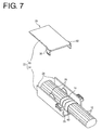
- the one or more wires 12 are arranged in the accommodation space in the protector main body portion 24 and the one or more, particularly the pair of fixing projecting portions 26 of the bottom plate portion 25 of the protector main body portion 24 at least partly are inserted into the one or more wire fixing recesses 46 of the wire fixing piece 40 to unite or join the wire fixing piece 40 and the protector main body portion 24.
- specified (predetermined or predeterminable) parts of the wires 12 in the extending direction ED are supported at a certain position on (particularly one end side of) the protector main body portion 24.
- the one or more lock pieces 32 at least partly are inserted into the one or more lock receiving portions 29 to be locked and fixed, thereby mounting the lid portion 30 on or to the protector main body portion 24. In this way, the wires with protector 10 are manufactured.
- the wire fixing piece 40 can be fixed to the protector main body portion 24 after the one or more wires 12 are fixed to the wire fixing piece 40 by the binding member 18.
- the operation of binding the wire fixing piece 40 by the binding member 18 can be performed without being interfered by the wire accommodating portion 22.
- the one or more wires 12 can be reliably positioned at the wire draw-out port 23 by fixing the wire fixing piece 40 to the protector main body portion 24. Further, since the one or more wires 12 are bound and fixed to the wire fixing piece 40 by the adhesive tape, they can be relatively inexpensively fixed.
- the binding member 18 particularly is protected by being at least partly accommodated into the wire accommodating portion 22, the state where the wires 12 and the wire fixing piece 40 are bound or maintained or fixed by the binding member 18 is more reliably maintained. In this way, the state where the wires 12 are more reliably fixed at the certain position with respect to the wire accommodating portion 22 is maintained.
- the wire accommodating portion 22 is composed of or comprises the protector main body portion 24 and the lid portion 30.
- the wires 12 can be easily at least partly accommodated in the protector main body portion 24 and the wire fixing piece 40 can be easily fixed in the protector main body portion 24.
- the wire draw-out port 23 particularly is closed on plural (e.g. four) sides by the protector main body portion 24 and the lid portion 30, at least parts of the wires 12 and the binding member 18 can be more reliably protected. Particularly, the exposure of the binding member 18 to water can be suppressed by the lid portion 30.
- the wire fixing piece 40 can be fixed to the wire accommodating portion 22 particularly by arranging the fixing projecting portion(s) 26 into the wire fixing recess(es) 46 with the bound portion 42 and the wire(s) 12 bound and fixed. At this time, since it is sufficient to arrange the fixing projecting portion(s) 26 into the wire fixing recess(es) 46 formed on (particularly the side parts of) the wide portion 44 wider than the bound portion 42, the fixing operation by this arrangement can be easily performed.
- one or more wire fixing recesses may be formed on the bottom plate portion and one or more fixing projecting portions projecting toward the bottom plate portion and to be arranged in the wire fixing recesses may be formed on the wire fixing piece.
- one fixing projecting portion may be formed on one side part of the bottom plate portion and only one wire fixing recess may be formed on one side part of the wire fixing piece.
- the other side part of the wire fixing piece i.e. where particularly no wire fixing recess is formed
- wire fixing recess particularly is formed as a hole penetrating through the wide portion, it is not always necessary.
- a bottomed recess recessed from the bottom plate portion side may be formed on the wide portion and a fixing projecting portion formed on the bottom plate portion and having a small height may be at least partly fitted into the bottomed recess. Further, the wire fixing recess may be open laterally of the wide portion.
- a plurality of (here, two) wire fixing pieces 40 are provided and can be united with a wire draw-out port 23 of a wire accommodating portion 22 particularly while being arranged substantially side by side. Note that the outline of bundles of wires 12 is shown in FIGS. 8 and 9 .
- a bottom plate portion 125 (as a particular base plate portion) corresponding to the bottom plate portion 25 is formed to be wider.
- a plurality of (two) pairs of fixing projecting portions 26 are formed particularly substantially side by side in a width direction on the bottom plate portion 125. It should be understood that the plurality of (two) pairs of fixing projecting portions 26 may also be arranged offset along the extending direction ED of the wires 12.
- wires 12 (bundle of the wires 12) are bound and fixed to each of the plurality of wire fixing pieces 40 in the same manner as above.
- Each pair of fixing projecting portions 26 are inserted into a pair of wire fixing recesses 46 of the corresponding wire fixing piece 40. In this way, the pair of wire fixing pieces 40 are united and fixed particularly substantially side by side to the wire draw-out port 23.
- a binding force by a binding member is hard to act and the wires are easily displaced in that part.
- the multitude of wires 12 can be divided into separate bundles and each bundle can be bound and fixed to the separate wire fixing piece 40.
- each wire fixing piece 40 can be formed to be relatively narrow, the wires 12 can be more reliably supported at a certain (predetermined or predeterminable) position on each wire fixing piece 40. As a result, the multitude of wires 12 can be more reliably fixed at the certain position by the plurality of wire fixing pieces 40.
- wire fixing pieces 40 particularly can be separately handled in binding and fixing the respective wire fixing pieces 40 and the wires 12, one binding operation does not interfere with the other binding operation.
- an integrated wire fixing piece 240 integrally or unitarily formed to a wire draw-out port 23 is further provided separately from the above wire fixing piece 40.
- the wire fixing piece 40 can be united with the wire draw-out port 23 on a side adjacent to the integrated wire fixing piece 240.
- a bottom plate portion 225 (as a particular base plate portion) corresponding to the bottom plate portion 25 is formed to be wider.
- the integrated wire fixing piece 240 extends outward (or along the extension direction ED of the wires 12) from a position of an end part of the bottom plate portion 225 near one side part.
- the integrated wire fixing piece 240 is an integrally or unitarily molded part in forming a protector main body portion 224 including the bottom plate portion 225 and the like.
- the integrated wire fixing piece 240 itself is configured similarly to a bound portion 42.
- a pair of fixing projecting portions 26 are provided to project at positions of (particularly the upper or inner surface of) the bottom plate portion 225 near the other side part.
- the pair of fixing projecting portions 26 particularly are formed at positions of the bottom plate portion 225 near the end part and the bound portion 42 is arranged to project from the bottom plate portion 225 similarly to the integrated wire fixing piece 240 here.
- the bound portion 42 may be arranged at a position to be accommodated in the wire draw-out port 23 as in the above embodiment.
- the arrangement of the integrated wire fixing piece 240 and the wire fixing piece 40 in an adjacent positional relationship also includes such a positional relationship.
- wire fixing piece 40 is united with the wide portion 23 by inserting the one or more, particularly the pair of fixing projecting portions 26 into the one or more, particularly the pair of wire fixing recesses 46 after the others of the multitude of wires 12 are bound and fixed to the bound portion 42.
- the multitude of wires 12 are divided, some of them are or can be fixed to the integrated wire fixing piece 24 and the others are or can be fixed to the wire fixing piece 40, the multitude of the wires 12 can be more reliably fixed at a certain (predetermined or predeterminable) position as in the above previous modification. Further, since the wire fixing piece 40 and the integrated wire fixing piece 240 can be separately handled in binding and fixing the wire fixing piece 40 or the integrated wire fixing piece 240 and the wires 12, one binding operation does not interfere with the other binding operation.
- a protector 20 includes a wire accommodating portion 22 and at least one wire fixing piece 40.
- the wire accommodating portion 22 is formed with an accommodation space capable of at least partly accommodating wires 12 and a wire draw-out port 23 for drawing out the wires 12 at least partly accommodated in the accommodation space to outside.
- At least one wire fixing piece 40 is formed separately from the wire accommodating portion 22 and unitable with or mountable to the wire draw-out port 23 in a state fixed at a certain position in an extending direction ED of the wires 12 by a binding member 18.
Landscapes
- Engineering & Computer Science (AREA)
- Architecture (AREA)
- Civil Engineering (AREA)
- Structural Engineering (AREA)
- Mechanical Engineering (AREA)
- Details Of Indoor Wiring (AREA)
Abstract
Description
- The present invention relates to a protector for protecting a wire, to an assembly of a wire and protector and to an assembling method therefor.
-
Japanese Unexamined Patent Publication No. 2012-85478 -
Japanese Unexamined Patent Publication No. 2012-100460 - However, according to the technology disclosed
Japanese Unexamined Patent Publication No. 2012-85478 - Further, according to the technology disclosed in
Japanese Unexamined Patent Publication No. 2012-100460 - Accordingly, the present invention aims to enable a wire to be easily and reliably positioned and fixed in a protector.
- This object is solved according to the invention by the features of the independent claims. Particular embodiments of the invention are subject of the dependent claims.
- According to one aspect, there is provided a protector which includes a wire accommodating portion formed with an accommodation space capable of at least partly accommodating at least one wire and a wire draw-out port for drawing out the wire accommodated in the accommodation space to outside, and at least one wire fixing piece formed separately from the wire accommodating portion and unitable with the wire draw-out port in a state fixed at a certain (predetermined or predeterminable) position in an extending direction of the wire by at least one binding member.
- Accordingly, the wire fixing piece can be fixed to the wire accommodating portion after the wire is fixed to the wire fixing piece by the binding member. Thus, the wire can be easily and reliably positioned and fixed in or to the protector.
- According to a particular embodiment, the wire fixing piece is unitable with or fixable to the wire accommodating portion at a position where at least a part of the binding member for binding and fixing the wire and the wire fixing piece is arranged in the wire accommodating portion.
- Accordingly, the binding member can be protected since at least the part of the binding member is arranged in the wire accommodating portion.
- Particularly, the wire accommodating portion includes a protector main body portion with a base plate portion (particularly a bottom plate portion) and one or more, particularly a pair of side wall portions standing from (particularly substantially opposite sides of) the base (bottom) plate portion, and a lid portion to be mounted on the protector main body portion to at least partly close an opening of the protector main body, particularly substantially facing the base (bottom) plate portion.
- Accordingly, the wire can be easily accommodated into the protector main body portion through the opening facing the bottom plate portion. By closing the opening with the lid portion, the wire and at least the part of the binding member can be protected.
- Further particularly, the wire fixing piece includes a bound portion to be bound and fixed to the wire and a wide portion wider than the bound portion, at least one fixing projecting portion is formed on one of a side part of the wide portion and the wire accommodating portion and a wire fixing recess, in which the fixing projecting portion is arrangeable, is formed on the other.
- Accordingly, the wire fixing piece can be fixed to the wire accommodating portion particularly by arranging the fixing projecting portion formed on the one of the side part of the wide portion and the wire accommodating portion in the wire fixing recess formed on the other with the bound portion and the wire bound and fixed. At this time, it is sufficient to arrange the fixing projecting portion in the wire fixing recess formed on the side part of the wide portion wider than the bound portion, wherefore a fixing operation by this arranging operation can be easily performed.
- Further particularly, a plurality of the wire fixing pieces are provided, and the plurality of wire fixing pieces are unitable or fixable substantially side by side with the wire draw-out port.
- Accordingly, an operation of binding and fixing the wire can be easily performed and the wire can be more reliably fixed since the wire can be bound and fixed to each of the plurality of wire fixing pieces.
- Further particularly, an integrated wire fixing piece is further provided which is integrally formed to the wire draw-out port.
- Further particularly, the wire fixing piece is unitable with the wire draw-out port on a side adjacent to the integrated wire fixing piece.
- Accordingly, the operation of binding and fixing the wire can be easily performed and the wire can be more reliably fixed, since the wire can be bound and fixed to each of the integrated wire fixing piece and the wire fixing piece.
- According to a further aspect, there is provided an assembly of wire with protector which includes a protector according to the above aspect of a particular embodiment thereof, a wire and a binding member for binding and fixing the wire and the wire fixing piece, and the wire fixing piece at least partly is accommodated in the accommodation space in a state where the wire fixing piece is united with the wire draw-out port and the wire is drawn out to outside from the wire draw-out port.
- According to a further aspect of the invention, there is provided a method of assembling a wire with a protector (i.e. producing an assembly of a wire with protector), in particular according to the above aspect or a particular embodiment thereof, comprising: binding and fixing at least one wire to at least one wire fixing piece of the protector; at least partly accommodating the wire fixing piece in an accommodation space of the protector thereby uniting the wire fixing piece with the wire draw-out port of the protector; and drawing out the wire to outside from the wire draw-out port.
- According to a particular embodiment, the wire fixing piece is united with the wire accommodating portion at a position where at least a part of the binding member for binding and fixing the wire and the wire fixing piece is arranged in the wire accommodating portion.
- Particularly, in the accommodating step the wire at least partly is enclosed by a protector main body portion with a base plate portion and one or more side wall portions standing from the base plate portion; and a lid portion is mounted on the protector main body portion to at least partly close an opening of the protector main body portion.
- Further particularly, the wire fixing piece includes a bound portion to be bound and fixed to the wire and a wide portion wider than the bound portion; and wherein at least one fixing projecting portion is formed on one of a side part of the wide portion and the wire accommodating portion and a wire fixing recess, in which the fixing projecting portion is arrangeable, is formed on the other.
- Further particularly, the method further comprises providing a plurality of the wire fixing pieces; and uniting the plurality of wire fixing pieces substantially side by side with the wire draw-out port.
- Further particularly, the method further comprises integrally or unitarily forming an integrated wire fixing piece to the wire draw-out port.
- Further particularly, the wire fixing piece is united with the wire draw-out port on a side adjacent to the integrated wire fixing piece.
- According to the above, the wire fixing piece can be fixed to the wire accommodating portion after the wire is fixed to the wire fixing piece by the binding member. Thus, the wire can be easily and reliably positioned and fixed in the protector.
- These and other objects, features and advantages of the present invention will become more apparent upon reading of the following detailed description of preferred embodiments and accompanying drawings. It should be understood that even though embodiments are separately described, single features thereof may be combined to additional embodiments.
-
FIG. 1 is a perspective view showing wires with protector according to an embodiment, -
FIG. 2 is an exploded perspective view showing the protector, -
FIG. 3 is a plan view showing a protector main body portion, -
FIG. 4 is a plan view showing a wire fixing piece, -
FIG. 5 is a plan view showing a lid portion, -
FIG. 6 is a diagram showing a manufacturing process of the wires with protector, -
FIG. 7 is a diagram showing the manufacturing process of the wires with protector, -
FIG. 8 is a diagram showing a protector according to a first modification, and -
FIG. 9 is a diagram showing a protector according to a second modification. - Hereinafter, a
protector 20 and one or more wires withprotector 10 according to a particular embodiment are described.FIG. 1 is a perspective view showing the wires withprotector 10. Note that one end part of theprotector 20 is shown, but the other end part is not shown inFIG. 1 and each of other figures. - The one or more wires with
protector 10 include theprotector 20, one ormore wires 12 and at least one bindingmember 18. - The
wire 12 particularly is such that an insulation coating is formed around a core which is a conductive wire. Thewire 12 particularly can supply power and/or transmit a signal. Here, the wires withprotector 10 particularly include a plurality ofwires 12. The plurality ofwires 12 at least partly may be branched in parts accommodated in theprotector 20 and/or outside theprotector 20. If the plurality ofwires 12 at least partly are branched in the parts accommodated in theprotector 20, theprotector 20 may have an opening for allowing the part(s) branched at an intermediate part in an extending direction of theprotector 20 to be extended to outside. - Connectors are mounted on (particularly end parts of) the plurality of
wires 12. The respective connectors are or may be connected to various electrical components mounted in a vehicle with the wires withprotector 10 assembled in the vehicle. Specifically, the plurality ofwires 12 are used as a wiring harness which is a wiring material in the vehicle. An optical fiber cable may be bundled together with thewires 12. Here is described an example in which theprotector 20 at least partly accommodates substantially linearly bound parts of the plurality ofwires 12. - The
protector 20 at least partly accommodates parts of (particularly the substantially linear parts of) the plurality ofwires 12. The plurality ofwires 12 are drawn out to outside through at least one wire draw-outport 23 on one end part of theprotector 20. The other end part of theprotector 20 may be configured similarly to the wire draw-outport 23 described here or may be so configured that a wire fixing piece is integrally or unitarily formed as before. -
FIG. 2 is an exploded perspective view showing theprotector 20,FIG. 3 is a plan view showing a protectormain body portion 24,FIG. 4 is a plan view showing awire fixing piece 40 andFIG. 5 is a plan view showing alid portion 30. - The
protector 20 includes at least onewire accommodating portion 22 and the at least onewire fixing piece 40. - The
wire accommodating portion 22 particularly substantially is formed into a tubular shape; here specifically into a rectangular or polygonal tubular shape. Although thewire accommodating portion 22 specifically is formed into a rectangular tube shape whose height is smaller than a width here, it is not essential. A (particularly substantially rectangular parallelepipedic) accommodation space capable of accommodating thewires 12 is formed in thewire accommodating portion 22. Further, the wire draw-outports 23 for drawing out the one ormore wires 12 to outside are formed on substantially opposite end parts of thewire accommodating portion 22. Here, the wire draw-outport 23 particularly is a rectangular or polygonal opening. - More specifically, the
wire accommodating portion 22 includes the protectormain body portion 24 and the at least onelid portion 30. - The protector
main body portion 24 particularly is a member molded of resin or the like and includes a bottom plate portion 25 (as a particular base plate portion) and one or more, particularly a pair ofside wall portions 28. - The
bottom plate portion 25 particularly substantially is in the form of a long and narrow plate. Thebottom plate portion 25 may be bent in a width and/or thickness direction thereof at an intermediate part in an extending direction thereof. - Specifically, the pair of
side wall portions 28 are formed to stand toward one principal surface side of thebottom plate portion 25 from (particularly substantially opposite side parts of) thebottom plate portion 25. Note that although the pair ofside wall portions 28 stand in a posture at an angle different from 0° or 180°, preferably substantially perpendicular to thebottom plate portion 25 here, theside wall portions 28 and thebottom plate portion 25 may be connected via curved parts. - Intermediate parts of the
wires 12 in the extending direction ED can be at least partly accommodated in a space substantially enclosed or defined by thebottom plate portion 25 and the one or more, particularly pair ofside wall portions 28. - One or more
fixing projecting portions 26 are formed on (particularly an opening end part of) thebottom plate portion 25 particularly where the wire draw-outport 23 is formed. These fixing projectingportions 26 are described in detail later in connection with thewire fixing piece 40. - Further, one or more
lock receiving portions 29 are provided on the one or moreside wall portions 28, particularly on parts of outer surfaces of the pair ofside wall portions 28 on a side substantially opposite to thebottom plate portion 25. Thelock receiving portion 29 includes anopening 29h penetrating in a direction perpendicular to thebottom plate portion 25 and at least onelock piece 32 of thelid portion 30 to be described later is locked and fixed to thelock receiving portion 29 by being at least partly inserted into thisopening 29h. - The
lid portion 30 particularly is a member molded of resin or the like and/or configured to be mountable on the protectormain body portion 24 to at least partly close an opening facing thebottom plate portion 25. Here, thelid portion 30 particularly substantially is in the form of a long and narrow piece similarly to thebottom plate portion 25 and/or configured to particularly substantially close the entire opening of the protectormain body portion 24 on the side substantially opposite to thebottom plate portion 25. - One or
more lock pieces 32 are provided to project at one or more positions respectively corresponding to the above one or morelock receiving portions 29 particularly on substantially opposite side parts of thelid portion 30. Thelock piece 32 particularly includes a plate-like portion 33 projecting from (particularly the side part of) thelid portion 30 substantially toward the protectormain body portion 24 and at least onelock protrusion 34 projecting on (particularly an outer surface of a tip part of) the plate-like portion 33. Thelock protrusion 34 particularly is formed into a shape whose height is gradually reduced toward a tip side of thelock piece 32. When thelock pieces 32 at least partly are inserted into theopenings 29h of thelock receiving portions 29, thelock protrusions 34 retain and lock (particularly peripheral edge parts of) theopenings 29h while coming out of theopenings 29h. In this way, thelock pieces 32 and thelock receiving portions 29 are locked and thelid portion 30 is mounted or fixed on the protectormain body portion 24. - Thus, the wire draw-out
port 23 on the end part of thewire accommodating portion 22 is surrounded on plural (e.g. four) sides by the protectormain body portion 24 and thelid portion 30. - Note that it is not essential to provide the
lid portion 30. Accordingly, the wire accommodating portion may be left open on the side opposite to the bottom plate portion. - The
wire fixing piece 40 particularly is a member molded of resin or the like separately from the abovewire accommodating portion 22 and unitable with or connectable to the wire draw-outport 23 in a state fixed at a certain (predetermined or predeterminable) position in the extending direction ED of thewires 12 by the bindingmember 18. - More specifically, the
wire fixing piece 40 substantially is in the form of a plate as a whole and particularly includes at least one boundportion 42 and at least onewide portion 44. - The bound
portion 42 particularly substantially is a plate-like part to be bound and fixed to the one ormore wires 12. The boundportion 42 preferably has a width smaller than an outer diameter of a bundle of the plurality ofwires 12. This enables a force of the bindingmember 18 for holding the one or more, particularly the plurality ofwires 12 in a bundled state to effectively act and particularly thewires 12 to be more reliably fixed in the bundled state at the certain position when the bindingmember 18 is wound on or provided on or at least partly around the bundle of thewires 12 and the boundportion 42. - Further, at least one part (particularly an edge part) of the bound portion 42 (particularly on a side substantially opposite to the wide portion 44) is formed into at least one retaining
portion 43 projecting toward one principal surface side of the boundportion 42. The bindingmember 18 is fixed (particularly wound) on a part of the boundportion 42 inwardly of the retainingportion 43. In this way, the bindingmember 18 is caught by the retainingportion 43, with the result that the fall-off of the bindingmember 18 from the boundportion 42 is suppressed. - The
wide portion 44 particularly is a substantially plate-like part integrally or unitarily formed to (particularly one end part of) the boundportion 42 to substantially spread or extend on the same plane. Thewide portion 44 particularly is formed to be wider than the boundportion 42. Preferably, thewide portion 44 is formed to have a width larger than the outer diameter of the bundle of the plurality ofwires 12. This causes one or more opposite end parts of thewide portion 44 to protrude laterally outwardly from the bundle of thewires 12 with the boundportion 42 fixed to the bundle of thewires 12. - The one or more
fixing projecting portions 26 are formed on one of thewide portion 44 and/or the wire draw-outport 23 of thewire accommodating portion 22 and the wire fixing recesses 46 are formed on the other. - Here, the
fixing projecting portions 26 particularly are formed on the protectormain body portion 24 of thewire accommodating portion 22 and the wire fixing recesses 46 are formed on thewide portion 44. - More specifically, one or more, particularly a pair of fixing projecting
portions 26 are formed on (particularly opposite side parts of an end part of) thebottom plate portion 25 of the protectormain body portion 24 where the wire draw-outport 23 is formed. - The one or more
fixing projecting portions 26 particularly are in the form of flat plates extending substantially along an extending direction of theside wall portions 28. This enables thewire fixing piece 40 to be held in a constant posture as much as possible in a state where thefixing projecting portions 26 at least partly are inserted and fitted in wire fixing recesses 46. Of course, thefixing projecting portions 26 may be in the form of round bars or rectangular bars or any other suitable shape. - A height of the
fixing projecting portions 26 particularly is set to be substantially equal to or smaller (slightly smaller) than that of theside wall portions 28. This makes tip sides of thefixing projecting portions 26 difficult to come out of the wire fixing recesses 46 in a state where thefixing projecting portions 26 are inserted in the wire fixing recesses 46. Of course, the height of thefixing projecting portions 26 may be smaller than in the above example. - Further, the tip parts of the
fixing projecting portions 26 particularly are formed to be gradually narrower and thinner toward the tip sides. This enables thefixing projecting portions 26 to be easily inserted into the wire fixing recesses 46. Of course, the tip parts of thefixing projecting portions 26 may be shaped to have the same dimensions as the remaining parts. - Further, opening parts of the wire fixing recesses 46 substantially facing the
bottom plate portion 25 particularly may be shaped to be gradually wider toward the boundportion 25. Further, thefixing projecting portions 26 particularly may be press-fitted into or engaged with the wire fixing recesses 46, thereby being retained. Furthermore, one or more lock projections for retaining and locking the wire fixing recesses 46 in a state where thefixing projecting portions 26 at least partly are inserted to the backs of the wire fixing recesses 46 particularly may be provided to project on thefixing projecting portions 26. - Further, the one or more, particularly the pair of fixing projecting
portions 26 are provided at positions spaced apart from the side wall portion(s) 28. An interval between the pair of fixing projectingportions 26 particularly is set to be substantially equal to or larger than the outer diameter of the bundle of thewires 12. This enables the bundle of thewires 12 to be arranged particularly between the pair of fixing projectingportions 26. - The wire fixing recesse(s) 46 particularly is/are formed at positions substantially corresponding to the (pair of) fixing projecting portion(s) 26 particularly on substantially opposite side parts of the
wide portion 44. - The wire fixing recesses 46 are formed into (particularly substantially rectangular) through holes. The wire fixing recesses 46 are preferably so shaped and dimensioned that the
fixing projecting portions 26 are fitted thereinto as closely as possible. - Note that parts at outer side(s) of the wire fixing recess(es) 46 located on the side of the
bottom plate portion 25 particularly is/are formed into protrusion(s) 48 particularly substantially projecting about the same distance as the retainingportion 43. Thus, when thewire fixing piece 40 is arranged on thebottom plate portion 25, the retainingportion 43 and the one or more, particularly the pair ofprotrusions 48 particularly are arranged in contact with the upper surface of thebottom plate portion 25. - When the one or more, particularly the pair of fixing projecting
portions 26 are inserted and arranged in the one or more, particularly the pair of wire fixing recesses 46, thewire fixing piece 40 is fixed at the certain (predetermined or predeterminable) position relative to the wire draw-outport 23. - In this state, the positions of the pair of fixing projecting
portions 26 particularly are so set that at least a part of the bindingmember 18 wound on the boundportion 42 and thewires 12 is arranged in thewire accommodating portion 22. Here, the pair of fixing projectingportions 26 particularly are formed at positions where the pair of wire fixing recesses 46 are arranged in a state where an end part of the boundportion 42 substantially is arranged in alignment with an edge part of the wire draw-outport 23. Thus, when the pair of fixing projectingportions 26 at least partly are inserted and arranged into the wire fixing recesses 46 and thewire fixing piece 40 is united with thewire accommodating portion 22, the bindingmember 18 binding the boundportion 42 and thewires 12 is arranged in the wire draw-outport 23 of thewire accommodating portion 22. - The binding
member 18 is a member for binding and fixing thewires 12 and thewire fixing piece 40. Here, the bindingmember 18 particularly is configured by an adhesive tape. The adhesive tape is such that an adhesive layer is formed on one principal surface of a band- or strip-like base material made e.g. of resin. By winding the adhesive tape substantially around thewires 12 and the boundportion 42 in a state where thewire fixing piece 40 substantially extends along thewires 12, thewires 12 and thewire fixing piece 40 are bound and fixed. Besides the adhesive tape, a binding band, cable clip or the like may be alternatively or additionally used as the bindingmember 18. - An operation of manufacturing the wires with
protector 10 is described. - First, the bound
portion 42 of thewire fixing piece 40 is arranged substantially along thewires 12 particularly substantially at a position below the outer peripheries of the wires 12 (here, bundle of the plurality of wires 12) at a certain (predetermined or predeterminable) position in the extending direction ED. Then, as shown inFIG. 6 , the bindingmember 18 is fixed to the wire(s) 12 and the boundportion 42, particularly the adhesive tape as the bindingmember 18 is wound around thewires 12 and the boundportion 42. This binding operation can be performed before the one ormore wires 12 at least partly are accommodated into the protectormain body portion 24. Of course, it is also possible to perform the above binding operation in a state where parts of thewires 12 to be bound are taken out of the protectormain body portion 24 with thewires 12 partly accommodated in the protectormain body portion 24. - Thereafter, as shown in
FIG. 7 , the one ormore wires 12 are arranged in the accommodation space in the protectormain body portion 24 and the one or more, particularly the pair of fixing projectingportions 26 of thebottom plate portion 25 of the protectormain body portion 24 at least partly are inserted into the one or more wire fixing recesses 46 of thewire fixing piece 40 to unite or join thewire fixing piece 40 and the protectormain body portion 24. In this way, specified (predetermined or predeterminable) parts of thewires 12 in the extending direction ED are supported at a certain position on (particularly one end side of) the protectormain body portion 24. - Then, the one or
more lock pieces 32 at least partly are inserted into the one or morelock receiving portions 29 to be locked and fixed, thereby mounting thelid portion 30 on or to the protectormain body portion 24. In this way, the wires withprotector 10 are manufactured. - According to the
protector 20 and the wires withprotector 10 configured as described above, thewire fixing piece 40 can be fixed to the protectormain body portion 24 after the one ormore wires 12 are fixed to thewire fixing piece 40 by the bindingmember 18. Thus, the operation of binding thewire fixing piece 40 by the bindingmember 18 can be performed without being interfered by thewire accommodating portion 22. In addition, the one ormore wires 12 can be reliably positioned at the wire draw-outport 23 by fixing thewire fixing piece 40 to the protectormain body portion 24. Further, since the one ormore wires 12 are bound and fixed to thewire fixing piece 40 by the adhesive tape, they can be relatively inexpensively fixed. - Further, since the binding
member 18 particularly is protected by being at least partly accommodated into thewire accommodating portion 22, the state where thewires 12 and thewire fixing piece 40 are bound or maintained or fixed by the bindingmember 18 is more reliably maintained. In this way, the state where thewires 12 are more reliably fixed at the certain position with respect to thewire accommodating portion 22 is maintained. - Note that it is not essential to accommodate the entire binding
member 18 in thewire accommodating portion 22. If at least a part of the bindingmember 18 is accommodated in thewire accommodating portion 22, that part can be protected by thewire accommodating portion 22. - Further, the
wire accommodating portion 22 is composed of or comprises the protectormain body portion 24 and thelid portion 30. Thus, thewires 12 can be easily at least partly accommodated in the protectormain body portion 24 and thewire fixing piece 40 can be easily fixed in the protectormain body portion 24. Since the wire draw-outport 23 particularly is closed on plural (e.g. four) sides by the protectormain body portion 24 and thelid portion 30, at least parts of thewires 12 and the bindingmember 18 can be more reliably protected. Particularly, the exposure of the bindingmember 18 to water can be suppressed by thelid portion 30. - Of course, it is not essential to arrange at least the part of the binding
member 18 in thewire accommodating portion 22 and the entire binding member may be exposed from the wire accommodating portion (see later-described modification shown inFIG. 9 ). - Further, since the one or more
fixing projecting portions 26 particularly are formed in thewire accommodating portion 22 and the one or more wire fixing recesses at least partly fittable to thefixing projecting portions 26 are formed on (particularly the side parts of) thewide portion 44 of thewire fixing piece 40, thewire fixing piece 40 can be fixed to thewire accommodating portion 22 particularly by arranging the fixing projecting portion(s) 26 into the wire fixing recess(es) 46 with the boundportion 42 and the wire(s) 12 bound and fixed. At this time, since it is sufficient to arrange the fixing projecting portion(s) 26 into the wire fixing recess(es) 46 formed on (particularly the side parts of) thewide portion 44 wider than the boundportion 42, the fixing operation by this arrangement can be easily performed. - Note that it is not essential to form the
fixing projecting portions 26 on thebottom plate portion 25 and the wire fixing recesses 46 on thewire fixing piece 40. Conversely, one or more wire fixing recesses may be formed on the bottom plate portion and one or more fixing projecting portions projecting toward the bottom plate portion and to be arranged in the wire fixing recesses may be formed on the wire fixing piece. - Further, although the pair of fixing projecting portions and the pair of wire fixing recesses particularly are formed here, it is not always necessary. For example, one fixing projecting portion may be formed on one side part of the bottom plate portion and only one wire fixing recess may be formed on one side part of the wire fixing piece. In this case, the other side part of the wire fixing piece (i.e. where particularly no wire fixing recess is formed) is or may be preferably pressed against the inner surface of the side wall portion.
- Further, although the wire fixing recess particularly is formed as a hole penetrating through the wide portion, it is not always necessary. A bottomed recess recessed from the bottom plate portion side may be formed on the wide portion and a fixing projecting portion formed on the bottom plate portion and having a small height may be at least partly fitted into the bottomed recess. Further, the wire fixing recess may be open laterally of the wide portion.
- Modifications based on the above embodiment are described.
- First, in a
protector 120 according to a modified embodiment shown inFIG. 8 , a plurality of (here, two)wire fixing pieces 40 are provided and can be united with a wire draw-outport 23 of awire accommodating portion 22 particularly while being arranged substantially side by side. Note that the outline of bundles ofwires 12 is shown inFIGS. 8 and9 . - More specifically, a bottom plate portion 125 (as a particular base plate portion) corresponding to the
bottom plate portion 25 is formed to be wider. A plurality of (two) pairs of fixing projectingportions 26 are formed particularly substantially side by side in a width direction on thebottom plate portion 125. It should be understood that the plurality of (two) pairs of fixing projectingportions 26 may also be arranged offset along the extending direction ED of thewires 12. - Further, the wires 12 (bundle of the wires 12) are bound and fixed to each of the plurality of
wire fixing pieces 40 in the same manner as above. Each pair of fixing projectingportions 26 are inserted into a pair of wire fixing recesses 46 of the correspondingwire fixing piece 40. In this way, the pair ofwire fixing pieces 40 are united and fixed particularly substantially side by side to the wire draw-outport 23. - According to this example, functions and effects similar to those of the above embodiment can be obtained.
- In addition, in the case of supporting a multitude of
wires 12 on the flatwire accommodating portion 22, there is an advantage of being able to more reliably fix the multitude ofwires 12 at a certain (predetermined or predeterminable) position. - Specifically, in the case of supporting a multitude of wires on a flat wire accommodating portion, it is considered to arrange a plurality of wires substantially side by side in a flat state on a wide wire fixing piece and bind and fix the wires. In this case, in a widthwise central part of the wide wire fixing piece, a binding force by a binding member is hard to act and the wires are easily displaced in that part.
- Contrary to this, in this modification, the multitude of
wires 12 can be divided into separate bundles and each bundle can be bound and fixed to the separatewire fixing piece 40. In this case, since eachwire fixing piece 40 can be formed to be relatively narrow, thewires 12 can be more reliably supported at a certain (predetermined or predeterminable) position on eachwire fixing piece 40. As a result, the multitude ofwires 12 can be more reliably fixed at the certain position by the plurality ofwire fixing pieces 40. - In addition, since the
wire fixing pieces 40 particularly can be separately handled in binding and fixing the respectivewire fixing pieces 40 and thewires 12, one binding operation does not interfere with the other binding operation. - Further, in a
protector 220 according to a further modification shown inFIG. 9 , an integratedwire fixing piece 240 integrally or unitarily formed to a wire draw-outport 23 is further provided separately from the abovewire fixing piece 40. Thewire fixing piece 40 can be united with the wire draw-outport 23 on a side adjacent to the integratedwire fixing piece 240. - More specifically, a bottom plate portion 225 (as a particular base plate portion) corresponding to the
bottom plate portion 25 is formed to be wider. The integratedwire fixing piece 240 extends outward (or along the extension direction ED of the wires 12) from a position of an end part of thebottom plate portion 225 near one side part. The integratedwire fixing piece 240 is an integrally or unitarily molded part in forming a protectormain body portion 224 including thebottom plate portion 225 and the like. The integratedwire fixing piece 240 itself is configured similarly to a boundportion 42. - Further, a pair of fixing projecting
portions 26 are provided to project at positions of (particularly the upper or inner surface of) thebottom plate portion 225 near the other side part. By inserting this pair of fixing projectingportions 26 into a pair of wire fixing recesses 46, thewire fixing piece 40 is united with thewide portion 23. - Note that the pair of fixing projecting
portions 26 particularly are formed at positions of thebottom plate portion 225 near the end part and the boundportion 42 is arranged to project from thebottom plate portion 225 similarly to the integratedwire fixing piece 240 here. Of course, the boundportion 42 may be arranged at a position to be accommodated in the wire draw-outport 23 as in the above embodiment. The arrangement of the integratedwire fixing piece 240 and thewire fixing piece 40 in an adjacent positional relationship also includes such a positional relationship. - Some of a multitude of
wires 12 are bound and fixed to the integratedwire fixing piece 240. Further, thewire fixing piece 40 is united with thewide portion 23 by inserting the one or more, particularly the pair of fixing projectingportions 26 into the one or more, particularly the pair of wire fixing recesses 46 after the others of the multitude ofwires 12 are bound and fixed to the boundportion 42. - According to this further modification, functions and effects similar to those of the above embodiment can be obtained for the configuration for binding and fixing the
wires 12 and thewire fixing piece 40. - Further, since the multitude of
wires 12 are divided, some of them are or can be fixed to the integratedwire fixing piece 24 and the others are or can be fixed to thewire fixing piece 40, the multitude of thewires 12 can be more reliably fixed at a certain (predetermined or predeterminable) position as in the above previous modification. Further, since thewire fixing piece 40 and the integratedwire fixing piece 240 can be separately handled in binding and fixing thewire fixing piece 40 or the integratedwire fixing piece 240 and thewires 12, one binding operation does not interfere with the other binding operation. - Note that the respective configurations described in the above embodiment and each modification can be appropriately combined unless they contradict each other.
- Accordingly, to enable a wire to be easily and reliably positioned and fixed in a protector, a
protector 20 includes awire accommodating portion 22 and at least onewire fixing piece 40. Thewire accommodating portion 22 is formed with an accommodation space capable of at least partlyaccommodating wires 12 and a wire draw-outport 23 for drawing out thewires 12 at least partly accommodated in the accommodation space to outside. At least onewire fixing piece 40 is formed separately from thewire accommodating portion 22 and unitable with or mountable to the wire draw-outport 23 in a state fixed at a certain position in an extending direction ED of thewires 12 by a bindingmember 18. - Although this invention has been described in detail above, the above description is illustrative in all aspects and this invention is not limited thereby. It should be understood that unillustrated numerous modifications can be made without departing from the scope of this invention as defined in the claims.
- Reference Signs
- 10
- wires with protector
- 12
- wire
- 18
- binding member
- 20, 120, 220
- protector
- 22
- wire accommodating portion
- 23
- wire draw-out port
- 24, 224
- protector main body portion
- 25, 125, 225
- bottom plate portion (base plate portion)
- 26
- fixing projecting portion
- 28
- side wall portion
- 30
- lid portion
- 40
- wire fixing piece
- 42
- bound portion
- 44
- wide portion
- 46
- wire fixing recess
- 240
- integrated wire fixing piece
Claims (15)
- A protector (20), comprising:a wire accommodating portion (22) formed with an accommodation space capable of at least partly accommodating at least one wire (12) and a wire draw-out port (23) for drawing out the wire (12) accommodated in the accommodation space to outside; andat least one wire fixing piece (40) formed separately from the wire accommodating portion (22) and unitable with the wire draw-out port (23) in a state fixed at a certain position in an extending direction (ED) of the wire (12) by at least one binding member (18).
- A protector according to claim 1, wherein the wire fixing piece (40) is unitable with the wire accommodating portion (22) at a position where at least a part of the binding member (18) for binding and fixing the wire (12) and the wire fixing piece (40) is arranged in the wire accommodating portion (22).
- A protector according to any one of the preceding claims, wherein the wire accommodating portion (22) includes:a protector main body portion (24; 224) with a base plate portion (25; 125; 225) and one or more side wall portions (28) standing from the base plate portion (25; 125; 225); anda lid portion (30) to be mounted on the protector main body portion (24; 224) to at least partly close an opening of the protector main body portion (24; 224).
- A protector according to any one of the preceding claims, wherein:the wire fixing piece (40) includes a bound portion (42) to be bound and fixed to the wire (12) and a wide portion (44) wider than the bound portion (42); andat least one fixing projecting portion (26) is formed on one of a side part of the wide portion (44) and the wire accommodating portion (22) and a wire fixing recess (46), in which the fixing projecting portion (26) is arrangeable, is formed on the other.
- A protector according to any one of the preceding claims, wherein:a plurality of the wire fixing pieces (40) are provided; andthe plurality of wire fixing pieces (40) are unitable substantially side by side with the wire draw-out port (23).
- A protector according to any one of the preceding claims, further comprising an integrated wire fixing piece (240) integrally formed to the wire draw-out port (23).
- A protector according to claim 6, wherein the wire fixing piece (40) is unitable with the wire draw-out port (23) on a side adjacent to the integrated wire fixing piece (240).
- An assembly of a wire (12) with protector (20), comprising:a protector (20) according to any one of the preceding claims;a wire (12); anda binding member (18) for binding and fixing the wire (12) and the wire fixing piece (40);wherein the wire fixing piece (40) at least partly is accommodated in the accommodation space in a state where the wire fixing piece (40) is united with the wire draw-out port (23) and the wire (12) is drawn out to outside from the wire draw-out port (23).
- A method of assembling a wire (12) with a protector (20), comprising:binding and fixing at least one wire (12) to at least one wire fixing piece (40) of the protector (20);at least partly accommodating the wire fixing piece (40) in an accommodation space of the protector (20) thereby uniting the wire fixing piece (40) with the wire draw-out port (23) of the protector (20); anddrawing out the wire (12) to outside from the wire draw-out port (23).
- A method according to claim 9, wherein the wire fixing piece (40) is united with the wire accommodating portion (22) at a position where at least a part of the binding member (18) for binding and fixing the wire (12) and the wire fixing piece (40) is arranged in the wire accommodating portion (22).
- A method according to claim 9 or 10, wherein in the accommodating step the wire (12) at least partly is enclosed by a protector main body portion (24; 224) with a base plate portion (25; 125; 225) and one or more side wall portions (28) standing from the base plate portion (25; 125; 225); and a lid portion (30) is mounted on the protector main body portion (24; 224) to at least partly close an opening of the protector main body portion (24; 224).
- A method according to any one of the preceding claims 9 to 11, wherein the wire fixing piece (40) includes a bound portion (42) to be bound and fixed to the wire (12) and a wide portion (44) wider than the bound portion (42); and wherein at least one fixing projecting portion (26) is formed on one of a side part of the wide portion (44) and the wire accommodating portion (22) and a wire fixing recess (46), in which the fixing projecting portion (26) is arrangeable, is formed on the other.
- A method according to any one of the preceding claims 9 to 12, further comprising providing a plurality of the wire fixing pieces (40); and uniting the plurality of wire fixing pieces (40) substantially side by side with the wire draw-out port (23).
- A method according to any one of the preceding claims 9 to 13, further comprising integrally forming an integrated wire fixing piece (240) to the wire draw-out port (23).
- A method according to claim 14, wherein the wire fixing piece (40) is united with the wire draw-out port (23) on a side adjacent to the integrated wire fixing piece (240).
Applications Claiming Priority (1)
| Application Number | Priority Date | Filing Date | Title |
|---|---|---|---|
| JP2015063811A JP2016185015A (en) | 2015-03-26 | 2015-03-26 | Protector and wire with the same |
Publications (1)
| Publication Number | Publication Date |
|---|---|
| EP3072748A1 true EP3072748A1 (en) | 2016-09-28 |
Family
ID=55589635
Family Applications (1)
| Application Number | Title | Priority Date | Filing Date |
|---|---|---|---|
| EP16000619.3A Withdrawn EP3072748A1 (en) | 2015-03-26 | 2016-03-15 | Protector, assembly of wire with protector, and assembling method therefor |
Country Status (3)
| Country | Link |
|---|---|
| US (1) | US9592776B2 (en) |
| EP (1) | EP3072748A1 (en) |
| JP (1) | JP2016185015A (en) |
Cited By (1)
| Publication number | Priority date | Publication date | Assignee | Title |
|---|---|---|---|---|
| EP4026735A1 (en) * | 2021-01-12 | 2022-07-13 | Yazaki Corporation | Wire harness routing method, wire harness routing structure, and wire harness protector |
Families Citing this family (9)
| Publication number | Priority date | Publication date | Assignee | Title |
|---|---|---|---|---|
| US10214161B2 (en) * | 2015-07-06 | 2019-02-26 | Sumitomo Wiring Systems, Ltd. | Wire housing protector |
| JP6793047B2 (en) * | 2017-01-25 | 2020-12-02 | 矢崎総業株式会社 | Protector and wire harness |
| JP6876461B2 (en) * | 2017-02-22 | 2021-05-26 | 矢崎総業株式会社 | Protector and protector manufacturing method |
| JP6951660B2 (en) * | 2017-05-24 | 2021-10-20 | 住友電装株式会社 | Wiring unit |
| JP2019078022A (en) * | 2017-10-22 | 2019-05-23 | 渡邉 啓祐 | Lighting conductor and curing device for bird injury wire and the like |
| US11662041B2 (en) | 2019-07-29 | 2023-05-30 | Erico International Corporation | Support clip |
| CN112909865B (en) * | 2019-12-04 | 2023-02-10 | 神讯电脑(昆山)有限公司 | A wire fixing component wire fixing part and electronic device |
| JP2022016785A (en) * | 2020-07-13 | 2022-01-25 | 住友電装株式会社 | Protector and wire harness |
| JP1774023S (en) * | 2023-10-24 | 2024-06-26 | Connector cover |
Citations (7)
| Publication number | Priority date | Publication date | Assignee | Title |
|---|---|---|---|---|
| JPH0666233U (en) * | 1993-02-26 | 1994-09-16 | 住友電装株式会社 | Protector for electric wire |
| US6229091B1 (en) * | 1998-08-25 | 2001-05-08 | Yazaki Corporation | Wire harness protector |
| US20030183413A1 (en) * | 2002-03-27 | 2003-10-02 | Yazaki Corporation | Harness fixing device |
| JP2012085478A (en) | 2010-10-14 | 2012-04-26 | Sumitomo Wiring Syst Ltd | Protector for vehicle |
| JP2012100460A (en) | 2010-11-04 | 2012-05-24 | Sumitomo Wiring Syst Ltd | Wire harness |
| WO2015001931A1 (en) * | 2013-07-01 | 2015-01-08 | 株式会社オートネットワーク技術研究所 | Protector and wire harness with protector |
| US20150041175A1 (en) * | 2013-08-09 | 2015-02-12 | Sumitomo Wiring Systems, Ltd. | Electrical wire holder |
Family Cites Families (9)
| Publication number | Priority date | Publication date | Assignee | Title |
|---|---|---|---|---|
| JPS63198324U (en) * | 1987-06-09 | 1988-12-21 | ||
| JPH0419938Y2 (en) * | 1987-12-17 | 1992-05-07 | ||
| JP2537153Y2 (en) * | 1991-12-20 | 1997-05-28 | 住友電装株式会社 | Wire harness protector |
| JP4261947B2 (en) * | 2003-03-14 | 2009-05-13 | 矢崎総業株式会社 | Harness fixture for sliding door feeding and feeding structure using it |
| JP2005160222A (en) * | 2003-11-26 | 2005-06-16 | Yazaki Corp | Protector lock structure and wire harness |
| JP4299211B2 (en) * | 2004-08-31 | 2009-07-22 | 住友電装株式会社 | Protector |
| JP4311431B2 (en) * | 2006-09-29 | 2009-08-12 | 住友電装株式会社 | Protector |
| JP4360392B2 (en) * | 2006-09-29 | 2009-11-11 | 住友電装株式会社 | Protector |
| JP4983525B2 (en) * | 2007-10-11 | 2012-07-25 | 住友電装株式会社 | Wire harness protector mounting structure |
-
2015
- 2015-03-26 JP JP2015063811A patent/JP2016185015A/en not_active Withdrawn
-
2016
- 2016-03-02 US US15/058,197 patent/US9592776B2/en not_active Expired - Fee Related
- 2016-03-15 EP EP16000619.3A patent/EP3072748A1/en not_active Withdrawn
Patent Citations (8)
| Publication number | Priority date | Publication date | Assignee | Title |
|---|---|---|---|---|
| JPH0666233U (en) * | 1993-02-26 | 1994-09-16 | 住友電装株式会社 | Protector for electric wire |
| US6229091B1 (en) * | 1998-08-25 | 2001-05-08 | Yazaki Corporation | Wire harness protector |
| US20030183413A1 (en) * | 2002-03-27 | 2003-10-02 | Yazaki Corporation | Harness fixing device |
| JP2012085478A (en) | 2010-10-14 | 2012-04-26 | Sumitomo Wiring Syst Ltd | Protector for vehicle |
| JP2012100460A (en) | 2010-11-04 | 2012-05-24 | Sumitomo Wiring Syst Ltd | Wire harness |
| WO2015001931A1 (en) * | 2013-07-01 | 2015-01-08 | 株式会社オートネットワーク技術研究所 | Protector and wire harness with protector |
| US20160156165A1 (en) * | 2013-07-01 | 2016-06-02 | Autonetworks Technologies, Ltd. | Protector and wiring harness with protector |
| US20150041175A1 (en) * | 2013-08-09 | 2015-02-12 | Sumitomo Wiring Systems, Ltd. | Electrical wire holder |
Cited By (4)
| Publication number | Priority date | Publication date | Assignee | Title |
|---|---|---|---|---|
| EP4026735A1 (en) * | 2021-01-12 | 2022-07-13 | Yazaki Corporation | Wire harness routing method, wire harness routing structure, and wire harness protector |
| CN114765351A (en) * | 2021-01-12 | 2022-07-19 | 矢崎总业株式会社 | Wire harness routing method, wire harness routing structure, and wire harness protector |
| US11600975B2 (en) | 2021-01-12 | 2023-03-07 | Yazaki Corporation | Wire harness routing method, wire harness routing structure, and wire harness protector |
| CN114765351B (en) * | 2021-01-12 | 2024-02-06 | 矢崎总业株式会社 | Wire harness routing method, wire harness routing structure and wire harness protector |
Also Published As
| Publication number | Publication date |
|---|---|
| US9592776B2 (en) | 2017-03-14 |
| JP2016185015A (en) | 2016-10-20 |
| US20160280158A1 (en) | 2016-09-29 |
Similar Documents
| Publication | Publication Date | Title |
|---|---|---|
| EP3072748A1 (en) | Protector, assembly of wire with protector, and assembling method therefor | |
| CN108290531B (en) | Cable guide device, wiring device, airbag module, steering wheel, and vehicle | |
| US20140038473A1 (en) | Terminal fitting | |
| KR20170094271A (en) | Plug | |
| CN109428221B (en) | electrical connector | |
| CN101814670A (en) | Cable-arraying insert for connectors | |
| MX2013006565A (en) | External Part Mounted Electric Wire, Wiring Harness Including the Same External Part Mounted Electric Wire, And Method for Fabricating the Same Wiring Harness. | |
| KR20130069590A (en) | Cable Organizer for Electrical Connectors | |
| CN102842873B (en) | Box main body | |
| CN104080655A (en) | Wire harness with clip and protect tube | |
| US9106007B2 (en) | Electrical junction box | |
| JP5947485B2 (en) | Relay connector | |
| US9231338B2 (en) | Variable wire strain relief connector | |
| JP6793047B2 (en) | Protector and wire harness | |
| JP5746580B2 (en) | Cable tie mounting structure | |
| US10150431B2 (en) | Holding part and method for fastening electrical wires and a wiring arrangement in a vehicle | |
| JP2017123746A (en) | Protector and wire harness including the same | |
| TW201702511A (en) | Cable management clasp for a cable assembly of a communication system | |
| WO2016067877A1 (en) | Wire harness module | |
| JP2012235555A (en) | Mounting method of electric wire protector and electric wire with protector | |
| JP6742854B2 (en) | Protector and wire harness | |
| CN104183969A (en) | Protective cover | |
| JP6217781B2 (en) | Wire protection member and wire harness module | |
| JP6191579B2 (en) | Wire harness module | |
| JP2012228086A (en) | Electric wire protector and component of the same |
Legal Events
| Date | Code | Title | Description |
|---|---|---|---|
| PUAI | Public reference made under article 153(3) epc to a published international application that has entered the european phase |
Free format text: ORIGINAL CODE: 0009012 |
|
| 17P | Request for examination filed |
Effective date: 20160324 |
|
| AK | Designated contracting states |
Kind code of ref document: A1 Designated state(s): AL AT BE BG CH CY CZ DE DK EE ES FI FR GB GR HR HU IE IS IT LI LT LU LV MC MK MT NL NO PL PT RO RS SE SI SK SM TR |
|
| AX | Request for extension of the european patent |
Extension state: BA ME |
|
| RBV | Designated contracting states (corrected) |
Designated state(s): AL AT BE BG CH CY CZ DE DK EE ES FI FR GB GR HR HU IE IS IT LI LT LU LV MC MK MT NL NO PL PT RO RS SE SI SK SM TR |
|
| RIC1 | Information provided on ipc code assigned before grant |
Ipc: H02G 3/04 20060101ALI20171215BHEP Ipc: H02G 3/00 20060101ALI20171215BHEP Ipc: B60R 16/02 20060101AFI20171215BHEP |
|
| GRAP | Despatch of communication of intention to grant a patent |
Free format text: ORIGINAL CODE: EPIDOSNIGR1 |
|
| INTG | Intention to grant announced |
Effective date: 20180130 |
|
| STAA | Information on the status of an ep patent application or granted ep patent |
Free format text: STATUS: THE APPLICATION IS DEEMED TO BE WITHDRAWN |
|
| 18D | Application deemed to be withdrawn |
Effective date: 20180612 |