EP3072723A1 - Vehicular drive device - Google Patents
Vehicular drive device Download PDFInfo
- Publication number
- EP3072723A1 EP3072723A1 EP14866569.8A EP14866569A EP3072723A1 EP 3072723 A1 EP3072723 A1 EP 3072723A1 EP 14866569 A EP14866569 A EP 14866569A EP 3072723 A1 EP3072723 A1 EP 3072723A1
- Authority
- EP
- European Patent Office
- Prior art keywords
- gear
- axis
- disposed
- electric machine
- rotary electric
- Prior art date
- Legal status (The legal status is an assumption and is not a legal conclusion. Google has not performed a legal analysis and makes no representation as to the accuracy of the status listed.)
- Granted
Links
Images


Classifications
-
- B—PERFORMING OPERATIONS; TRANSPORTING
- B60—VEHICLES IN GENERAL
- B60K—ARRANGEMENT OR MOUNTING OF PROPULSION UNITS OR OF TRANSMISSIONS IN VEHICLES; ARRANGEMENT OR MOUNTING OF PLURAL DIVERSE PRIME-MOVERS IN VEHICLES; AUXILIARY DRIVES FOR VEHICLES; INSTRUMENTATION OR DASHBOARDS FOR VEHICLES; ARRANGEMENTS IN CONNECTION WITH COOLING, AIR INTAKE, GAS EXHAUST OR FUEL SUPPLY OF PROPULSION UNITS IN VEHICLES
- B60K6/00—Arrangement or mounting of plural diverse prime-movers for mutual or common propulsion, e.g. hybrid propulsion systems comprising electric motors and internal combustion engines
- B60K6/20—Arrangement or mounting of plural diverse prime-movers for mutual or common propulsion, e.g. hybrid propulsion systems comprising electric motors and internal combustion engines the prime-movers consisting of electric motors and internal combustion engines, e.g. HEVs
- B60K6/22—Arrangement or mounting of plural diverse prime-movers for mutual or common propulsion, e.g. hybrid propulsion systems comprising electric motors and internal combustion engines the prime-movers consisting of electric motors and internal combustion engines, e.g. HEVs characterised by apparatus, components or means specially adapted for HEVs
- B60K6/40—Arrangement or mounting of plural diverse prime-movers for mutual or common propulsion, e.g. hybrid propulsion systems comprising electric motors and internal combustion engines the prime-movers consisting of electric motors and internal combustion engines, e.g. HEVs characterised by apparatus, components or means specially adapted for HEVs characterised by the assembly or relative disposition of components
-
- B—PERFORMING OPERATIONS; TRANSPORTING
- B60—VEHICLES IN GENERAL
- B60K—ARRANGEMENT OR MOUNTING OF PROPULSION UNITS OR OF TRANSMISSIONS IN VEHICLES; ARRANGEMENT OR MOUNTING OF PLURAL DIVERSE PRIME-MOVERS IN VEHICLES; AUXILIARY DRIVES FOR VEHICLES; INSTRUMENTATION OR DASHBOARDS FOR VEHICLES; ARRANGEMENTS IN CONNECTION WITH COOLING, AIR INTAKE, GAS EXHAUST OR FUEL SUPPLY OF PROPULSION UNITS IN VEHICLES
- B60K6/00—Arrangement or mounting of plural diverse prime-movers for mutual or common propulsion, e.g. hybrid propulsion systems comprising electric motors and internal combustion engines
- B60K6/20—Arrangement or mounting of plural diverse prime-movers for mutual or common propulsion, e.g. hybrid propulsion systems comprising electric motors and internal combustion engines the prime-movers consisting of electric motors and internal combustion engines, e.g. HEVs
- B60K6/42—Arrangement or mounting of plural diverse prime-movers for mutual or common propulsion, e.g. hybrid propulsion systems comprising electric motors and internal combustion engines the prime-movers consisting of electric motors and internal combustion engines, e.g. HEVs characterised by the architecture of the hybrid electric vehicle
- B60K6/44—Series-parallel type
- B60K6/445—Differential gearing distribution type
-
- B—PERFORMING OPERATIONS; TRANSPORTING
- B60—VEHICLES IN GENERAL
- B60K—ARRANGEMENT OR MOUNTING OF PROPULSION UNITS OR OF TRANSMISSIONS IN VEHICLES; ARRANGEMENT OR MOUNTING OF PLURAL DIVERSE PRIME-MOVERS IN VEHICLES; AUXILIARY DRIVES FOR VEHICLES; INSTRUMENTATION OR DASHBOARDS FOR VEHICLES; ARRANGEMENTS IN CONNECTION WITH COOLING, AIR INTAKE, GAS EXHAUST OR FUEL SUPPLY OF PROPULSION UNITS IN VEHICLES
- B60K6/00—Arrangement or mounting of plural diverse prime-movers for mutual or common propulsion, e.g. hybrid propulsion systems comprising electric motors and internal combustion engines
- B60K6/20—Arrangement or mounting of plural diverse prime-movers for mutual or common propulsion, e.g. hybrid propulsion systems comprising electric motors and internal combustion engines the prime-movers consisting of electric motors and internal combustion engines, e.g. HEVs
- B60K6/22—Arrangement or mounting of plural diverse prime-movers for mutual or common propulsion, e.g. hybrid propulsion systems comprising electric motors and internal combustion engines the prime-movers consisting of electric motors and internal combustion engines, e.g. HEVs characterised by apparatus, components or means specially adapted for HEVs
- B60K6/36—Arrangement or mounting of plural diverse prime-movers for mutual or common propulsion, e.g. hybrid propulsion systems comprising electric motors and internal combustion engines the prime-movers consisting of electric motors and internal combustion engines, e.g. HEVs characterised by apparatus, components or means specially adapted for HEVs characterised by the transmission gearings
- B60K6/365—Arrangement or mounting of plural diverse prime-movers for mutual or common propulsion, e.g. hybrid propulsion systems comprising electric motors and internal combustion engines the prime-movers consisting of electric motors and internal combustion engines, e.g. HEVs characterised by apparatus, components or means specially adapted for HEVs characterised by the transmission gearings with the gears having orbital motion
-
- B—PERFORMING OPERATIONS; TRANSPORTING
- B60—VEHICLES IN GENERAL
- B60K—ARRANGEMENT OR MOUNTING OF PROPULSION UNITS OR OF TRANSMISSIONS IN VEHICLES; ARRANGEMENT OR MOUNTING OF PLURAL DIVERSE PRIME-MOVERS IN VEHICLES; AUXILIARY DRIVES FOR VEHICLES; INSTRUMENTATION OR DASHBOARDS FOR VEHICLES; ARRANGEMENTS IN CONNECTION WITH COOLING, AIR INTAKE, GAS EXHAUST OR FUEL SUPPLY OF PROPULSION UNITS IN VEHICLES
- B60K6/00—Arrangement or mounting of plural diverse prime-movers for mutual or common propulsion, e.g. hybrid propulsion systems comprising electric motors and internal combustion engines
- B60K6/20—Arrangement or mounting of plural diverse prime-movers for mutual or common propulsion, e.g. hybrid propulsion systems comprising electric motors and internal combustion engines the prime-movers consisting of electric motors and internal combustion engines, e.g. HEVs
- B60K6/50—Architecture of the driveline characterised by arrangement or kind of transmission units
- B60K6/54—Transmission for changing ratio
-
- F—MECHANICAL ENGINEERING; LIGHTING; HEATING; WEAPONS; BLASTING
- F16—ENGINEERING ELEMENTS AND UNITS; GENERAL MEASURES FOR PRODUCING AND MAINTAINING EFFECTIVE FUNCTIONING OF MACHINES OR INSTALLATIONS; THERMAL INSULATION IN GENERAL
- F16H—GEARING
- F16H3/00—Toothed gearings for conveying rotary motion with variable gear ratio or for reversing rotary motion
- F16H3/44—Toothed gearings for conveying rotary motion with variable gear ratio or for reversing rotary motion using gears having orbital motion
- F16H3/72—Toothed gearings for conveying rotary motion with variable gear ratio or for reversing rotary motion using gears having orbital motion with a secondary drive, e.g. regulating motor, in order to vary speed continuously
- F16H3/727—Toothed gearings for conveying rotary motion with variable gear ratio or for reversing rotary motion using gears having orbital motion with a secondary drive, e.g. regulating motor, in order to vary speed continuously with at least two dynamo electric machines for creating an electric power path inside the gearing, e.g. using generator and motor for a variable power torque path
-
- B—PERFORMING OPERATIONS; TRANSPORTING
- B60—VEHICLES IN GENERAL
- B60Y—INDEXING SCHEME RELATING TO ASPECTS CROSS-CUTTING VEHICLE TECHNOLOGY
- B60Y2200/00—Type of vehicle
- B60Y2200/90—Vehicles comprising electric prime movers
- B60Y2200/92—Hybrid vehicles
-
- B—PERFORMING OPERATIONS; TRANSPORTING
- B60—VEHICLES IN GENERAL
- B60Y—INDEXING SCHEME RELATING TO ASPECTS CROSS-CUTTING VEHICLE TECHNOLOGY
- B60Y2400/00—Special features of vehicle units
- B60Y2400/70—Gearings
- B60Y2400/73—Planetary gearings
-
- B—PERFORMING OPERATIONS; TRANSPORTING
- B60—VEHICLES IN GENERAL
- B60Y—INDEXING SCHEME RELATING TO ASPECTS CROSS-CUTTING VEHICLE TECHNOLOGY
- B60Y2400/00—Special features of vehicle units
- B60Y2400/80—Differentials
-
- Y—GENERAL TAGGING OF NEW TECHNOLOGICAL DEVELOPMENTS; GENERAL TAGGING OF CROSS-SECTIONAL TECHNOLOGIES SPANNING OVER SEVERAL SECTIONS OF THE IPC; TECHNICAL SUBJECTS COVERED BY FORMER USPC CROSS-REFERENCE ART COLLECTIONS [XRACs] AND DIGESTS
- Y02—TECHNOLOGIES OR APPLICATIONS FOR MITIGATION OR ADAPTATION AGAINST CLIMATE CHANGE
- Y02T—CLIMATE CHANGE MITIGATION TECHNOLOGIES RELATED TO TRANSPORTATION
- Y02T10/00—Road transport of goods or passengers
- Y02T10/60—Other road transportation technologies with climate change mitigation effect
- Y02T10/62—Hybrid vehicles
-
- Y—GENERAL TAGGING OF NEW TECHNOLOGICAL DEVELOPMENTS; GENERAL TAGGING OF CROSS-SECTIONAL TECHNOLOGIES SPANNING OVER SEVERAL SECTIONS OF THE IPC; TECHNICAL SUBJECTS COVERED BY FORMER USPC CROSS-REFERENCE ART COLLECTIONS [XRACs] AND DIGESTS
- Y10—TECHNICAL SUBJECTS COVERED BY FORMER USPC
- Y10S—TECHNICAL SUBJECTS COVERED BY FORMER USPC CROSS-REFERENCE ART COLLECTIONS [XRACs] AND DIGESTS
- Y10S903/00—Hybrid electric vehicles, HEVS
- Y10S903/902—Prime movers comprising electrical and internal combustion motors
- Y10S903/903—Prime movers comprising electrical and internal combustion motors having energy storing means, e.g. battery, capacitor
- Y10S903/904—Component specially adapted for hev
- Y10S903/909—Gearing
- Y10S903/91—Orbital, e.g. planetary gears
- Y10S903/911—Orbital, e.g. planetary gears with two or more gear sets
-
- Y—GENERAL TAGGING OF NEW TECHNOLOGICAL DEVELOPMENTS; GENERAL TAGGING OF CROSS-SECTIONAL TECHNOLOGIES SPANNING OVER SEVERAL SECTIONS OF THE IPC; TECHNICAL SUBJECTS COVERED BY FORMER USPC CROSS-REFERENCE ART COLLECTIONS [XRACs] AND DIGESTS
- Y10—TECHNICAL SUBJECTS COVERED BY FORMER USPC
- Y10S—TECHNICAL SUBJECTS COVERED BY FORMER USPC CROSS-REFERENCE ART COLLECTIONS [XRACs] AND DIGESTS
- Y10S903/00—Hybrid electric vehicles, HEVS
- Y10S903/902—Prime movers comprising electrical and internal combustion motors
- Y10S903/903—Prime movers comprising electrical and internal combustion motors having energy storing means, e.g. battery, capacitor
- Y10S903/904—Component specially adapted for hev
- Y10S903/915—Specific drive or transmission adapted for hev
- Y10S903/917—Specific drive or transmission adapted for hev with transmission for changing gear ratio
Definitions
- the present invention relates to a vehicular drive device that includes an input member drivingly coupled to an internal combustion engine through a damper, a first rotary electric machine, a second rotary electric machine, and a differential gear device, and an output device drivingly coupled to a wheel.
- Patent Document 1 A device described in Japanese Patent Application Publication No. 2013-166548 (Patent Document 1) is already known as an example of the vehicular drive device as mentioned above.
- a rotational axis center [first axis A1] of the input member [input shaft I], the first rotary electric machine [MG1], and the differential gear device [power transfer PT], a rotational axis center [second axis A2] of the second rotary electric machine [MG2], and a rotational axis center [third axis A3] of the output device [output differential gear device DF] are disposed so as to be parallel to one another and positioned at vertices of a triangle as viewed in the axial direction.
- One gear [first gear 42] of a counter gear mechanism [C] disposed inside the triangle is commonly meshed with a gear [output gear 22] that rotates together with an output element [ring gear R] of the differential gear device and an output gear [37] of the second rotary electric machine.
- a damper and the counter gear mechanism are disposed overlapping with each other as viewed in the axial direction and the counter gear mechanism and the second rotary electric machine are disposed overlapping with each other as viewed in the axial direction. Therefore, a length in the axial direction along the rotational axis center of the second rotary electric machine is likely to be long.
- Patent Document 2 discloses a device which has a same base configuration and in which a motive power transmission pathway from the differential gear device [P] side and a motive power transmission pathway from the second rotary electric machine [electric motor M] side with respect to the output device [differential device D] are separately configured. By separating the two motive power transmission pathways with respect to the output device, it is possible to set a total gear ratio without changing positions of the respective axes and also reduce restrictions in a vehicle mounted state.
- the vehicular drive device is a vehicular drive device that includes an input member drivingly coupled to an internal combustion engine through a damper, a first rotary electric machine, a second rotary electric machine, a differential gear device including three rotational elements, and an output device drivingly coupled to a wheel, and in which, among the three rotational elements of the differential gear device, one rotational element is drivingly coupled to the input member, another rotational element is drivingly coupled to the first rotary electric machine, an output element as a resting rotational element is drivingly coupled to the output device, and the second rotary electric machine is drivingly coupled to the output device, the vehicular drive device including:
- the term “drivingly coupled” means a state in which two rotational elements are coupled so as to be capable of transmitting a driving force (synonymous with torque) therebetween.
- This concept includes a state in which two rotational elements are coupled so as to rotate together and a state in which the two rotational elements are coupled so as to be capable of transmitting a driving force therebetween through one or more transmission members.
- Such transmission members include various members (e.g., a shaft, a gear mechanism, and a belt) for transmitting rotation at the same speed or a changed speed, and may include engagement devices (e.g., a friction engagement device and a mesh engagement device) for selectively transmitting the rotation and the driving force.
- the term “drivingly coupled” utilized with respect to each rotational element of the differential gear device refers to a drivingly coupled state without going through another rotational element of the differential gear device.
- rotary electric machine is used as a concept including all of a motor (electric motor), a generator (electric generator), and a motor generator that functions as both a motor and a generator.
- the first gear mechanism that transmits a driving force between the output element and the output device and the second gear mechanism that transmits a driving force between the second rotary electric machine and the output device are individually provided. Therefore, restrictions in arrangements of the respective parts can be reduced.
- the second gear mechanism can be disposed distant from the damper as viewed in the axial direction.
- the second gear mechanism can be disposed also distant from the first gear mechanism as viewed in the axial direction.
- the second gear mechanism and the second rotary electric machine can be disposed close to the damper side in the axial direction.
- the length in the axial direction along the rotational axis center of the second rotary electric machine can be shortened.
- the second gear mechanism is disposed so as not to overlap with the damper as viewed in an axial direction.
- the phrase "overlapping as viewed in a certain direction” means that when a virtual line parallel to a viewing direction is moved in each direction orthogonal to the virtual line, a region where the virtual line intersects both of the two members exists in at least one part. Consequently, with respect to the arrangement of two members, the phrase "not overlapping as viewed in a certain direction” means that when a virtual line parallel to a viewing direction is moved in each direction orthogonal to the virtual line, a region where the virtual line intersects both of the two members does not exist.
- the interference between the second gear mechanism and the damper can be avoided regardless of the positional relationship in the axial direction between the second gear mechanism and the damper.
- the second gear mechanism is disposed close to the damper side in the axial direction as well as the internal combustion engine side.
- the second rotary electric machine can be disposed close to the internal combustion engine side.
- the second gear mechanism includes a third gear that is meshed with a second output gear of the second rotary electric machine and a fourth gear that is meshed with an input gear of the output device at a position different from the third gear in an axial direction, and the third gear is disposed on a side opposite to the second rotary electric machine side in the axial direction with respect to the fourth gear.
- the entire second gear mechanism is disposed on the side opposite to the second rotary electric machine side with respect to the input gear of the output device.
- the second gear mechanism can be disposed close to the damper side as well as the internal combustion engine side in the axial direction.
- the second rotary electric machine can be disposed close to the internal combustion engine side. Therefore, the length in the axial direction along the rotational axis center of the second rotary electric machine can be effectively shortened.
- the third gear is disposed so as not to overlap with the damper as viewed in the axial direction and so as to overlap with the damper as viewed in a radial direction.
- the length in the axial direction along the rotational axis center of the second rotary electric machine can be effectively shortened.
- the first gear mechanism includes a first gear that is meshed with a first output gear rotating together with the output element and a second gear that is meshed with an input gear of the output device at a position different from the first gear in an axial direction, and the second gear is disposed on the damper side in the axial direction with respect the first gear.
- the input gear of the output device is disposed close to the damper side in the axial direction, therefore, the second gear mechanism can be disposed close to the damper side.
- the second rotary electric machine can be disposed close to the damper side. Therefore, the length in the axial direction along the rotational axis center of the second rotary electric machine can be effectively shortened.
- the second axis and the third axis are disposed on one side in a horizontal direction with respect to the first axis, and the second axis is disposed on an upper side with respect to the third axis.
- a layout suitable to a vehicular drive device with a multiaxial configuration can be realized, and the length in the axial direction along the rotational axis center of the second rotary electric machine can be shortened.
- a vehicular drive device 1 according to the present embodiment is a drive device for a hybrid vehicle provided with both an internal combustion engine E and rotary electric machines MG1, MG2 as driving sources of a wheel W.
- the vehicular drive device 1 is configured as a drive device for a so-called two-motor split type hybrid vehicle.
- the vehicular drive device 1 according to the present embodiment is configured as a drive device for a FF (Front Engine Front Drive) vehicle.
- FF Front Engine Front Drive
- the directions of the respective members indicate directions in a state where the members are mounted in the vehicular drive device 1.
- the vehicular drive device 1 is provided with an input shaft 10 drivingly coupled to the internal combustion engine E, a differential gear device 20, a first rotary electric machine 30, a second rotary electric machine 40, and an output device 70 drivingly coupled to the wheel W.
- the vehicular drive device 1 is provided with a first gear mechanism 50 that transmits a driving force between the differential gear device 20 and the output device 70 and a second gear mechanism 60 that transmits a driving force between the second rotary electric machine 40 and the output device 70 individually.
- these are housed in a case (drive device case) 3.
- the input shaft 10, the differential gear device 20, and the first rotary electric machine 30 are disposed on a first axis X1 that is common thereto.
- the input shaft 10, the differential gear device 20, and the first rotary electric machine 30 are disposed side by side on the first axis X1 in this order from the internal combustion engine E side.
- the second rotary electric machine 40 is disposed on a second axis X2 that is different from the first axis X1.
- the output device 70 is disposed on a third axis X3 that is different from the first axis X1 and the second axis X2.
- the first axis X1, the second axis X2, and the third axis X3 are disposed so as to be parallel to one another.
- a direction that is parallel to the respective axes X1 to X3 is defined as "axial direction.”
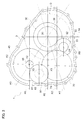
- the first axis X1, the second axis X2, and the third axis X3 are disposed so as to be positioned at vertices of a triangle as viewed in the axial direction.
- the second axis X2 and the third axis X3 are disposed on one side in a horizontal direction with respect to the first axis X1.
- the second axis X2 and the third axis X3 are disposed at a nearly equal position in the horizontal direction as viewed in the axial direction.
- the second axis X2 is disposed on an upper side with respect to the third axis X3.
- the third axis X3 is disposed on a lower side with respect to the first axis X1 and the second axis X2 is disposed on the upper side with respect to the first axis X1.
- the input shaft 10 is drivingly coupled to the internal combustion engine E.
- the internal combustion engine E is a motor (e.g., a gasoline engine or a diesel engine) that outputs mechanical power by being driven by combustion of fuel in the engine.
- the input shaft 10 is drivingly coupled to an output shaft (an internal combustion engine output shaft such as a crank shaft) of the internal combustion engine E.
- the input shaft 10 is drivingly coupled to the internal combustion engine E through a damper D that is disposed on the same axis (on the first axis X1) as the input shaft 10. It is preferable that the input shaft 10 is drivingly coupled to the internal combustion engine E through a clutch, etc. in addition to the damper D.
- the input shaft 10 corresponds to "input member.”
- the input shaft 10 is drivingly coupled to the differential gear device 20.
- the differential gear device 20 is configured by a planetary gear mechanism having three rotational elements of a sun gear 21, a carrier 22, and a ring gear 23.
- the differential gear device 20 includes the carrier 22 that supports a plurality of pinion gears, and the sun gear 21 and the ring gear 23 that are both meshed with the pinion gears.
- the differential gear device 20 is configured by a single pinion planetary gear mechanism.
- the three rotational elements of the differential gear device 20 correspond to the sun gear 21, the carrier 22, and the ring gear 23 in an order of rotational speed.
- the "order of rotational speed” means an order of rotational speed in a rotating state of the respective rotational elements 21 to 23.
- the rotational speeds of the respective rotational elements 21 to 23 change depending on the rotating state of the differential gear device 20. However, the order (high-low) of the rotational speeds of the respective rotational elements 21 to 23 is constant because the order is determined by the structure of the differential gear device 20. Note that the order of the rotational speeds of the respective rotational elements 21 to 23 is equivalent to an order of allocation of the respective rotational elements 21 to 23 in a velocity diagram (also, referred to as a collinear chart: refer to FIG. 2 ).
- the first rotary electric machine 30 is drivingly coupled to the sun gear 21, the input shaft 10 is drivingly coupled to the carrier 22, and the output device 70 is drivingly coupled to the ring gear 23.
- the first rotary electric machine 30 is drivingly coupled to the sun gear 21 without going through the carrier 22 or the ring gear 23, the input shaft 10 is drivingly coupled to the carrier 22 without going through the sun gear 21 or the ring gear 23, and the output device 70 is drivingly coupled to the ring gear 23 without going through the sun gear 21 or the carrier 22.
- the ring gear 23 corresponds to "output member.”
- FIG. 2 is a velocity diagram showing an operation state of the differential gear device 20.
- a vertical axis corresponds to the rotational speeds of the respective rotational elements. "0" indicates that the rotational speed is zero, the upper side represents positive rotational speed, and the lower side represents negative rotational speed.
- a plurality of vertical lines placed in parallel corresponds to the rotational elements 21 to 23 of the differential gear device 20, respectively.
- the straight line shown by thick line indicates an operation state of the differential gear device 20.
- the differential gear device 20 distributes torque of the internal combustion engine E that is transmitted to the input shaft 10 to the first rotary electric machine 30 and the ring gear 23. That is, in the differential gear device 20, the carrier 22 that is medium in the order of rotational speed is drivingly coupled to the input shaft 10 so as to rotate together, and the torque of the input shaft 10 (internal combustion engine E) transmitted to the carrier 22 is distributed to the sun gear 21 that is at one end and the ring gear 23 that is at the other end in the order of rotational speed. The torque damped with respect to the torque of the internal combustion engine E is transmitted to the sun gear 21 as torque for generating electric power. The first rotary electric machine 30 mainly outputs reactive torque (regenerated torque) with respect to the torque distributed to the sun gear 21 to generate electric power. The torque damped with respect to the torque of the internal combustion engine E is transmitted to the ring gear 23 as torque for driving the wheel W. In the present embodiment, the differential gear device 20 functions as a power transfer (differential gear device for power transfer).
- the ring gear 23 is integrally provided on an inner peripheral surface of a cylindrical differential output member 25 and a first output gear 26 is further integrally provided on an outer peripheral surface of the differential output member 25.
- the first output gear 26 is provided on an end portion of the differential output member 25 on the first rotary electric machine 30 side (on the side opposite to the internal combustion engine E side). In such manner, the ring gear 23 and the first output gear 26 are configured so as to rotate together.
- the first output gear 26 is meshed with a first gear 51 of the first gear mechanism 50.
- the ring gear 23 and the first output gear 26 that rotates together with the ring gear 23 are drivingly coupled to the output device 70 through the first gear mechanism 50.
- the first rotary electric machine 30 includes a first stator 31 that is fixed to the case 3, and a first rotor 32 that is rotatably supported on a radially inner side of the first stator 31.
- the first rotor 32 is coupled to a first rotor shaft 33 so as to rotate together.
- the sun gear 21 is provided on the end portion of the first rotor shaft 33 on the internal combustion engine E side. In such a manner, the first rotor 32 is drivingly coupled to the sun gear 21 of the differential gear device 20 through the first rotor shaft 33.
- the first rotary electric machine 30 is able to function as a motor (electric motor) that receives a supply of electric power and generates power, as well as function as a generator (electric generator) that receives a supply of power and generates electric power.
- the first rotary electric machine 30 is electrically connected to an electric storage device (battery, capacitor, etc., not shown).
- the first rotary electric machine 30, as described above mainly functions as a generator that generates electric power using torque of the input shaft 10 (internal combustion engine E) that is inputted through the differential gear device 20.
- the first rotary electric machine 30 may function as a motor when a vehicle travels on a highway, when the internal combustion engine E is started, etc.
- the second rotary electric machine 40 includes a second stator 41 that is fixed to the case 3, and a second rotor 42 that is rotatably supported on a radially inner side of the second stator 41.
- the second rotor 42 is coupled to a second rotor shaft 43 so as to rotate together.
- a second output gear 45 is provided on the end portion of the second rotor shaft 43 on the internal combustion engine E side. In such a manner, the second rotor 42 is drivingly coupled to the second output gear 45 through the second rotor shaft 43.
- the second output gear 45 is meshed with a third gear 61 of the second gear mechanism 60.
- the second output gear 45 is drivingly coupled to the output device 70 through the second gear mechanism 60.
- the second rotary electric machine 40 is able to function as a motor as well as function as a generator.
- the second rotary electric machine 40 is electrically connected to an electric storage device (not shown).
- the second rotary electric machine 40 mainly functions as a motor (assist motor) that assist a driving force for causing a vehicle to travel. Note that the second rotary electric machine 40 may function as a generator when the vehicle decelerates, etc.
- the first gear mechanism 50 transmits a driving force between the ring gear 23 that is an output member of the differential gear device 20 and the output device 70.
- the first gear mechanism 50 includes the first gear 51, a second gear 52 that is provided at a position different from the first gear 51 in the axial direction, and a first connecting shaft 53 that connects the two gears 51, 52.
- the first gear mechanism 50 is disposed on a fourth axis X4 that is parallel to the first axis X1 and is different from the first axis X1, the second axis X2, and the third axis X3.
- the first gear 51 is meshed with the first output gear 26 that rotates together with the ring gear 23.
- the second gear 52 is meshed with an input gear 71 of the output device 70.
- the second gear 52 is disposed on the internal combustion engine E side (damper D side) in the axial direction with respect to the first gear 51.
- the diameter of the second gear 52 is formed smaller (the number of teeth to be smaller) than the diameter of the first gear 51.
- the first gear mechanism 50 functions as a first deceleration mechanism (first counter deceleration mechanism) that decelerates the output rotation from the differential gear device 20 (amplifies the output torque from the differential gear device 20 at the same time) and transmits the decelerated rotation to the output device 70.
- the second gear mechanism 60 transmits a driving force between the second rotary electric machine 40 and the output device 70.
- the second gear mechanism 60 includes the third gear 61, a fourth gear 62 that is provided at a position different from the third gear 61 in the axial direction, and a second connecting shaft 63 that connects the two gears 61, 62.
- the second gear mechanism 60 is disposed on a fifth axis X5 that is parallel to the first axis X1 and is different from the first axis X1, the second axis X2, the third axis X3, and the fourth axis X4.
- the third gear 61 is meshed with the second output gear 45 of the second rotary electric machine 40.
- the fourth gear 62 is meshed with the input gear 71 of the output device 70.
- the third gear 61 is disposed on the side opposite to the second rotary electric machine 40 side in the axial direction with respect to the fourth gear 62.
- the third gear 61 is disposed on the internal combustion engine E side (damper D side) in the axial direction with respect to the fourth gear 62.
- the diameter of the fourth gear 62 is formed smaller (the number of teeth to be smaller) than the diameter of the third gear 61.
- the second gear mechanism 60 functions as a second deceleration mechanism (second counter deceleration mechanism) that decelerates the output rotation from the second rotary electric machine 40 (amplifies the output torque from the second rotary electric machine 40 at the same time) and transmits the decelerated rotation to the output device 70.
- the output device 70 includes the input gear 71 and a main body 72 coupled to the input gear 71.
- the main body 72 is disposed on the internal combustion engine E side (damper side) in the axial direction with respect to the input gear 71.
- the input gear 71 of the output device 70 is meshed with both the second gear 52 of the first gear mechanism 50 and the fourth gear 62 of the second gear mechanism 60.
- the input gear 71 is meshed with the second gear 52 and the fourth gear 62 at positions different from each other in a circumferential direction with reference to the third axis X3 (refer to FIG. 3 ).
- the main body 72 includes a plurality of bevel gears that are meshed with each other and a housing case that houses the plurality of bevel gears, and constitute a differential gear mechanism.
- the output device 70 distributes and transmits rotation and torque inputted from the differential gear device 20 side and the second rotary electric machine 40 side to the input gear 71 through the two gear mechanisms 50, 60 that are independent of each other to the two, left and right, output shafts 80 (i.e., two, left and right, wheels W) at the main body 72.
- the output device 70 functions as an output device (output differential gear device) having the differential gear mechanism.
- the entire device is preferably downsized as much as possible.
- the vehicular drive device 1 for a FF vehicle that is disposed adjacent to the internal combustion engine E in a width direction of the vehicle is preferably downsized especially in the axial direction.
- Such a demand is firstly applied to the parts on the first axis X1, on which a plurality of constituent parts (the differential gear device 20, the first rotary electric machine 30, and the damper D) are disposed side by side.
- the entire differential gear device 20 is disposed overlapping with the differential output member 25 as viewed in a radial direction with reference to the first axis X1 in the inner side of the cylindrical differential output member 25. Therefore, the entire differential gear device 20 can be disposed inside a space in the axial direction occupied by the differential output member 25.
- the first output gear 26 is integrally provided in an outer peripheral surface of the differential output member 25, the first output gear 26 can be also disposed in the space in the axial direction occupied by the differential output member 25.
- the motive power transmission pathway between the differential gear device 20 and the output device 70 and the motive power transmission pathway between the second rotary electric machine 40 and the output device 70 are individually provided and the arrangement of the respective motive power transmission pathways is optimized.
- a virtual plane including both the first axis X1 and the third axis X3 is defined as a first reference plane R1.
- a virtual plane including both the second axis X2 and the third axis X3 is defined as a second reference plane R2.
- a virtual plane including both the first axis X1 and the second axis X2 is defined as a third reference plane R3.
- a virtual perpendicular plane including the first axis X1 is defined as a fourth reference plane R4.
- a virtual horizontal plane including the first axis X1 is defined as a fifth reference plane R5.
- a virtual horizontal plane including the second axis X2 is defined as a sixth reference plane R6.
- a virtual horizontal plane including the third axis X3 is defined as a seventh reference plane R7.
- the fourth axis X4 that is the rotational axis center of the first gear mechanism 50 that transmits a driving force between the differential gear device 20 and the output device 70 is disposed so as to be positioned on the third axis X3 side with respect to the third reference plane R3.
- the fifth axis X5 that is the rotational axis center of the second gear mechanism 60 that transmits a driving force between the second rotary electric machine 40 and the output device 70 is also disposed so as to be positioned on the third axis X3 side with respect to the third reference plane R3.
- Both the first gear mechanism 50 and the second gear mechanism 60 are disposed so as to be positioned, as a whole, on the third axis X3 side with respect to the third reference plane R3.
- both the first gear mechanism 50 and the second gear mechanism 60 are disposed so as to be positioned in a major portion on an outer side of a triangle pole-shaped space surrounded by the three reference planes R1 to R3.
- the fourth axis X4 that is the rotational axis center of the first gear mechanism 50 is disposed so as to be positioned on the side opposite to the second axis X2 side with respect to the first reference plane R1.
- the first gear mechanism 50 is disposed so as to be positioned as a whole on the side opposite to the second axis X2 side with respect to the first reference plane R1.
- the fourth axis X4 is disposed so as to be positioned on the side opposite (lower side) to the second axis X2 side with respect to the seventh reference plane R7.
- Both the second gear 52 and the first connecting shaft 53 constituting the first gear mechanism 50 are disposed so as to be positioned as a whole on the side opposite (lower side) to the second axis X2 side with respect to the seventh reference plane R7.
- the first gear 51 constituting the first gear mechanism 50 is disposed so as to be positioned partially on the second axis X2 side (upper side) with respect to the seventh reference plane R7.
- the fourth axis X4 is disposed so as to be positioned on the first axis X1 side with respect to the second reference plane R2 and on the third axis X3 side with respect to the fourth reference plane R4.
- the first gear mechanism 50 is disposed so as to be positioned as a whole on the first axis X1 side with respect to the second reference plane R2 and on the third axis X3 side with respect to the fourth reference plane R4. In such a manner, the first gear mechanism 50 is disposed as a whole in a space sectioned by the second reference plane R2, the first reference plane R1, and the fourth reference plane R4.
- the first gear mechanism 50 is disposed, in a major portion excluding a part of the first gear 51, in a space sectioned by the second reference plane R2, the seventh reference plane R7, and the fourth reference plane R4.
- the first gear mechanism 50 includes a portion overlapping with the damper D as viewed in the axial direction.
- the first gear mechanism 50 does not include a portion overlapping with the second rotary electric machine 40 as viewed in the axial direction.
- the fifth axis X5 that is the rotational axis center of the second gear mechanism 60 is disposed so as to be positioned on the side opposite to the first axis X1 side with respect to the second reference plane R2.
- Both the fourth gear 62 and the second connecting shaft 63 constituting the second gear mechanism 60 are disposed so as to be positioned as a whole on the side opposite to the first axis X1 side with respect to the second reference plane R2.
- the third gear 61 constituting the second gear mechanism 60 is disposed so as to be positioned partially on the first axis X1 side with respect to the second reference plane R2.
- the second gear mechanism 60 is disposed so as to be positioned as a whole on the side opposite to the first axis X1 side with respect to the eighth reference plane R8.
- the fifth axis X5 is disposed so as to be positioned on the second axis X2 side with respect to the first reference plane R1 and on the third axis X3 side with respect to the third reference plane R3.
- the second gear mechanism 60 is disposed so as to be positioned as a whole on the second axis X2 side with respect to the first reference plane R1 and on the third axis X3 side with respect to the third reference plane R3.
- the fifth axis X5 is disposed so as to be positioned on the second axis X2 side (upper side) with respect to the fifth reference plane R5 and the third axis X3 side (lower side) with respect to the sixth reference plane R6.
- Both the fourth gear 62 and the second connecting shaft 63 constituting the second gear mechanism 60 are disposed so as to be positioned as a whole on the second axis X2 side (upper side) with respect to the fifth reference plane R5 and the third axis X3 side (lower side) with respect to the sixth reference plane R6.
- the third gear 61 constituting the second gear mechanism 60 is disposed so as to be positioned as a whole on the third axis X3 side (lower side) with respect to the sixth reference plane R6 and partially on the third axis X3 side (lower side) with respect to the fifth reference plane R5.
- the second gear mechanism 60 is disposed as a whole in a space sectioned by the seventh reference plane R7, the eighth reference plane R8, and the third reference plane R3.
- the second gear mechanism 60 is disposed, in a major portion excluding a part of the third gear 61, in a space sectioned by the fifth reference plane R5, the second reference plane R2, and the sixth reference plane R6.
- the second gear mechanism 60 is disposed largely distant from the damper D as viewed in the axial direction and disposed so as not to overlap with the damper D as viewed in the axial direction.
- the second gear mechanism 60 is disposed largely distant also from the first gear mechanism 50 as viewed in the axial direction and disposed so as not to overlap with the first gear mechanism 50 as viewed in the axial direction.
- the interference between the second gear mechanism 60 and the first gear mechanism 50 in the axial direction can be avoided, and the interference between the second gear mechanism 60 and the damper D in the axial direction can be avoided.
- the second gear mechanism 60 close to the damper D side in the axial direction.
- the second gear mechanism 60 close to the internal combustion engine E side in the axial direction.
- the second gear 52 meshed with the input gear 71 of the output device 70 is disposed on the damper D side in the axial direction with respect to the first gear 51
- the fourth gear 62 meshed with the input gear 71 is disposed on the side opposite to the damper D side in the axial direction with respect to the third gear 61.
- the first output gear 26 and the first gear 51 "the second gear 52, the input gear 71, and the fourth gear 62," and “the third gear 61 and the second output gear 45" are disposed so as to approach the internal combustion engine E side in the axial direction in the mentioned order.
- the second gear mechanism 60 can be disposed close to the internal combustion engine E side in the axial direction.
- the third gear 61 of the second gear mechanism 60 not overlapping with the damper D as viewed in the axial direction is disposed so as to include a portion overlapping with the damper D as viewed in the radial direction with reference to the fifth axis X5. That is, the second gear mechanism 60 is disposed adjacent to the internal combustion engine E side in the axial direction to the extent that at least a part of the second gear mechanism 60 occupies the same position in the axial direction as the damper D.
- the second rotary electric machine 40 also can be disposed close to the internal combustion engine E side in the axial direction.
- the vehicular drive device 1 differs from the aforementioned first embodiment in a configuration in which the first gear mechanism 50 is constituted by an idler gear 55 formed by a single gear.
- the first gear mechanism 50 is constituted by an idler gear 55 formed by a single gear.
- differences from the first embodiment are mainly explained. Note that items not specifically mentioned have the same configuration as the first embodiment.
- the first gear mechanism 50 includes a single discoid member 56 and a support shaft 57 that supports the discoid member 56 at a position of the rotational axis center thereof.
- the idler gear 55 is formed on an outer peripheral surface of the discoid member 56.
- the idler gear 55 is an intermediate gear that is provided between the first output gear 26 that rotates together with the ring gear 23 of the differential gear device 20 and the input gear 71 of the output device 70 so as to mesh with each other.
- the idler gear 55 matches the rotational direction of the first output gear 26 with the rotational direction of the input gear 71 as well as functions to fill an inter-shaft distance between the first output gear 26 and the input gear 71.
- the idler gear 55 is also referred to as an idle gear.
- the fourth axis X4 that is the rotational axis center of the first gear mechanism 50 is disposed so as to be positioned on the side opposite to the second axis X2 side with respect to the first reference plane R1.
- the first gear mechanism 50 is disposed so as to be positioned as a whole on the side opposite to the second axis X2 side with respect to the first reference plane R1.
- the fourth axis X4 is disposed so as to be positioned on the side (lower side) opposite to the second axis X2 side with respect to the seventh reference plane R7.
- the idler gear 55 constituting the first gear mechanism 50 is disposed so as to be positioned partially on the second axis X2 side (upper side) with respect to the seventh reference plane R7.
- the fourth axis X4 is disposed so as to be positioned on the first axis X1 side with respect to the second reference plane R2 and on the third axis X3 side with respect to the fourth reference plane R4.
- the idler gear 55 constituting the first gear mechanism 50 is disposed so as to be positioned as a whole on the first axis X1 side with respect to the second reference plane R2 and the third axis X3 side with respect to the fourth reference plane R4. In such a manner, the idler gear 55 constituting the first gear mechanism 50 is disposed as a whole in a space sectioned by the second reference plane R2, the first reference plane R1, and the fourth reference plane R4.
- the first output gear 26 is formed on a portion on the internal combustion engine E side with respect to the center in the axial direction of the differential output member 25.
- the first output gear 26, the idler gear 55, the input gear 71, and the fourth gear 62 are disposed at the same position in the axial direction.
- the third gear 61 and the second output gear 45 are disposed on the internal combustion engine E side in the axial direction with respect to these members.
- the second gear mechanism 60 can be disposed close to the internal combustion engine E side in the axial direction.
- the present invention may be applied to a drive device for a hybrid vehicle.
Landscapes
- Engineering & Computer Science (AREA)
- Mechanical Engineering (AREA)
- Chemical & Material Sciences (AREA)
- Combustion & Propulsion (AREA)
- Transportation (AREA)
- General Engineering & Computer Science (AREA)
- Hybrid Electric Vehicles (AREA)
- Retarders (AREA)
- Electric Propulsion And Braking For Vehicles (AREA)
- Arrangement Or Mounting Of Propulsion Units For Vehicles (AREA)
Abstract
Description
- The present invention relates to a vehicular drive device that includes an input member drivingly coupled to an internal combustion engine through a damper, a first rotary electric machine, a second rotary electric machine, and a differential gear device, and an output device drivingly coupled to a wheel.
- A device described in Japanese Patent Application Publication No.
2013-166548 Patent Document 1, a rotational axis center [first axis A1] of the input member [input shaft I], the first rotary electric machine [MG1], and the differential gear device [power transfer PT], a rotational axis center [second axis A2] of the second rotary electric machine [MG2], and a rotational axis center [third axis A3] of the output device [output differential gear device DF] are disposed so as to be parallel to one another and positioned at vertices of a triangle as viewed in the axial direction. One gear [first gear 42] of a counter gear mechanism [C] disposed inside the triangle is commonly meshed with a gear [output gear 22] that rotates together with an output element [ring gear R] of the differential gear device and an output gear [37] of the second rotary electric machine. However, in the device inPatent Document 1, a damper and the counter gear mechanism are disposed overlapping with each other as viewed in the axial direction and the counter gear mechanism and the second rotary electric machine are disposed overlapping with each other as viewed in the axial direction. Therefore, a length in the axial direction along the rotational axis center of the second rotary electric machine is likely to be long. - On the other hand, Japanese Patent Application Publication No.
2001-246953 Patent Document 1. -
- Patent Document 1: Japanese Patent Application Publication No.
2013-166548 JP 2013-166548 A - Patent Document 2: Japanese Patent Application Publication No.
2001-246953 JP 2001-246953 A - Therefore, it is desired, in a vehicular drive device with a multiaxial configuration that is coupled to a damper, to shorten the length in the axial direction along the rotational axis center of the second rotary electric machine.
- The vehicular drive device according to the present disclosure is a vehicular drive device that includes an input member drivingly coupled to an internal combustion engine through a damper, a first rotary electric machine, a second rotary electric machine, a differential gear device including three rotational elements, and an output device drivingly coupled to a wheel, and in which, among the three rotational elements of the differential gear device, one rotational element is drivingly coupled to the input member, another rotational element is drivingly coupled to the first rotary electric machine, an output element as a resting rotational element is drivingly coupled to the output device, and the second rotary electric machine is drivingly coupled to the output device, the vehicular drive device including:
- a first gear mechanism that transmits a driving force between the output element and the output device, and
- a second gear mechanism that transmits a driving force between the second rotary electric machine and the output device, wherein
- the damper, the differential gear device, and the first rotary electric machine are disposed side by side on a first axis that is common thereto,
- the second rotary electric machine is disposed on a second axis that is parallel to the first axis and is different from the first axis,
- the output device is disposed on a third axis that is parallel to the first axis and is different from the first axis and the second axis,
- the first gear mechanism is disposed on a fourth axis that is positioned on a side opposite to the second axis side with respect to a first reference plane that is a plane including both the first axis and the third axis, and
- the second gear mechanism is disposed on a fifth axis that is positioned on a side opposite to the first axis side with respect to the a second reference plane that is a plane including both the second axis and the third axis.
- In the present application, the term "drivingly coupled" means a state in which two rotational elements are coupled so as to be capable of transmitting a driving force (synonymous with torque) therebetween. This concept includes a state in which two rotational elements are coupled so as to rotate together and a state in which the two rotational elements are coupled so as to be capable of transmitting a driving force therebetween through one or more transmission members. Such transmission members include various members (e.g., a shaft, a gear mechanism, and a belt) for transmitting rotation at the same speed or a changed speed, and may include engagement devices (e.g., a friction engagement device and a mesh engagement device) for selectively transmitting the rotation and the driving force. The term "drivingly coupled" utilized with respect to each rotational element of the differential gear device refers to a drivingly coupled state without going through another rotational element of the differential gear device.
- In addition, the term "rotary electric machine" is used as a concept including all of a motor (electric motor), a generator (electric generator), and a motor generator that functions as both a motor and a generator.
- According to such a configuration, the first gear mechanism that transmits a driving force between the output element and the output device and the second gear mechanism that transmits a driving force between the second rotary electric machine and the output device are individually provided. Therefore, restrictions in arrangements of the respective parts can be reduced. In addition, by disposing the second gear mechanism on the fifth axis that is positioned on the side opposite to the first axis side with respect to the second reference plane including both the second axis and the third axis, the second gear mechanism can be disposed distant from the damper as viewed in the axial direction. In addition, by disposing the first gear mechanism on the fourth axis that is positioned on the side opposite to the second axis side with respect to the first reference plane including both the first axis and the third axis, the second gear mechanism can be disposed also distant from the first gear mechanism as viewed in the axial direction. Thereby, the second gear mechanism and the second rotary electric machine can be disposed close to the damper side in the axial direction. Thus, the length in the axial direction along the rotational axis center of the second rotary electric machine can be shortened.
- Preferable aspects of the vehicular drive device according to the present disclosure will be described below. Note that the scope of the present invention is not limited to the preferable aspects described below.
- In one aspect, preferably, the second gear mechanism is disposed so as not to overlap with the damper as viewed in an axial direction.
- In the present application, with respect to the arrangement of two members, the phrase "overlapping as viewed in a certain direction" means that when a virtual line parallel to a viewing direction is moved in each direction orthogonal to the virtual line, a region where the virtual line intersects both of the two members exists in at least one part. Consequently, with respect to the arrangement of two members, the phrase "not overlapping as viewed in a certain direction" means that when a virtual line parallel to a viewing direction is moved in each direction orthogonal to the virtual line, a region where the virtual line intersects both of the two members does not exist.
- According to such a configuration, the interference between the second gear mechanism and the damper can be avoided regardless of the positional relationship in the axial direction between the second gear mechanism and the damper. Thus, the second gear mechanism is disposed close to the damper side in the axial direction as well as the internal combustion engine side. As a result, the second rotary electric machine can be disposed close to the internal combustion engine side. Thereby, the length of in the axial direction along the rotational axis center of the second rotary electric machine can be effectively shortened.
- In one aspect, preferably, the second gear mechanism includes a third gear that is meshed with a second output gear of the second rotary electric machine and a fourth gear that is meshed with an input gear of the output device at a position different from the third gear in an axial direction, and the third gear is disposed on a side opposite to the second rotary electric machine side in the axial direction with respect to the fourth gear.
- According to such a configuration, the entire second gear mechanism is disposed on the side opposite to the second rotary electric machine side with respect to the input gear of the output device. Thus, the second gear mechanism can be disposed close to the damper side as well as the internal combustion engine side in the axial direction. As a result, the second rotary electric machine can be disposed close to the internal combustion engine side. Therefore, the length in the axial direction along the rotational axis center of the second rotary electric machine can be effectively shortened.
- In one aspect, preferably, the third gear is disposed so as not to overlap with the damper as viewed in the axial direction and so as to overlap with the damper as viewed in a radial direction.
- According to such a configuration, compared to a configuration in which the third gear overlaps with the damper as viewed in the axial direction, the length in the axial direction along the rotational axis center of the second rotary electric machine can be effectively shortened.
- In one aspect, preferably, the first gear mechanism includes a first gear that is meshed with a first output gear rotating together with the output element and a second gear that is meshed with an input gear of the output device at a position different from the first gear in an axial direction, and the second gear is disposed on the damper side in the axial direction with respect the first gear.
- According to such a configuration, the input gear of the output device is disposed close to the damper side in the axial direction, therefore, the second gear mechanism can be disposed close to the damper side. As a result, the second rotary electric machine can be disposed close to the damper side. Therefore, the length in the axial direction along the rotational axis center of the second rotary electric machine can be effectively shortened.
- In one aspect, preferably, in a vehicle mounted state, the second axis and the third axis are disposed on one side in a horizontal direction with respect to the first axis, and the second axis is disposed on an upper side with respect to the third axis.
- According to such a configuration, a layout suitable to a vehicular drive device with a multiaxial configuration can be realized, and the length in the axial direction along the rotational axis center of the second rotary electric machine can be shortened.
-
- [
FIG. 1] FIG. 1 is a skeleton view of a vehicular drive device according to a first embodiment. - [
FIG. 2] FIG. 2 is a velocity diagram of a differential gear device. - [
FIG. 3] FIG. 3 is a schematic view showing an arrangement of parts as viewed in an axial direction. - [
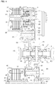
FIG. 4] FIG. 4 is a partial sectional view of the vehicular drive device. - [
FIG. 5] FIG. 5 is a skeleton view of a vehicular drive device according to a second embodiment. - [
FIG. 6] FIG. 6 is a schematic view showing an arrangement of parts as viewed in the axial direction. - [
FIG. 7] FIG. 7 is a partial sectional view of the vehicular drive device. - [
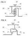
FIG. 8] FIG. 8 is a skeleton view showing another mode of the differential gear device. - [
FIG. 9] FIG. 9 is a skeleton view showing another mode of the differential gear device. - A first embodiment of a vehicular drive device is explained with reference to drawings. A
vehicular drive device 1 according to the present embodiment is a drive device for a hybrid vehicle provided with both an internal combustion engine E and rotary electric machines MG1, MG2 as driving sources of a wheel W. Thevehicular drive device 1 is configured as a drive device for a so-called two-motor split type hybrid vehicle. In addition, thevehicular drive device 1 according to the present embodiment is configured as a drive device for a FF (Front Engine Front Drive) vehicle. - In the following explanation, terms relating to a direction, a position, etc. of respective members are used as a concept that includes a condition with difference due to an error that is acceptable in operation. In addition, the directions of the respective members indicate directions in a state where the members are mounted in the
vehicular drive device 1. - As shown in
FIG. 1 , thevehicular drive device 1 is provided with aninput shaft 10 drivingly coupled to the internal combustion engine E, adifferential gear device 20, a first rotaryelectric machine 30, a second rotaryelectric machine 40, and anoutput device 70 drivingly coupled to the wheel W. In addition, thevehicular drive device 1 is provided with afirst gear mechanism 50 that transmits a driving force between thedifferential gear device 20 and theoutput device 70 and asecond gear mechanism 60 that transmits a driving force between the second rotaryelectric machine 40 and theoutput device 70 individually. As shown inFIG. 3 , these are housed in a case (drive device case) 3. - As shown in
FIGS. 1 and4 , theinput shaft 10, thedifferential gear device 20, and the first rotaryelectric machine 30 are disposed on a first axis X1 that is common thereto. Theinput shaft 10, thedifferential gear device 20, and the first rotaryelectric machine 30 are disposed side by side on the first axis X1 in this order from the internal combustion engine E side. The second rotaryelectric machine 40 is disposed on a second axis X2 that is different from the first axis X1. Theoutput device 70 is disposed on a third axis X3 that is different from the first axis X1 and the second axis X2. The first axis X1, the second axis X2, and the third axis X3 are disposed so as to be parallel to one another. In the present embodiment, a direction that is parallel to the respective axes X1 to X3 is defined as "axial direction." - As shown in
FIG. 3 , the first axis X1, the second axis X2, and the third axis X3 are disposed so as to be positioned at vertices of a triangle as viewed in the axial direction. In the present embodiment, as viewed in the axial direction in a vehicle mounted state, the second axis X2 and the third axis X3 are disposed on one side in a horizontal direction with respect to the first axis X1. The second axis X2 and the third axis X3 are disposed at a nearly equal position in the horizontal direction as viewed in the axial direction. In addition, the second axis X2 is disposed on an upper side with respect to the third axis X3. In the present embodiment, the third axis X3 is disposed on a lower side with respect to the first axis X1 and the second axis X2 is disposed on the upper side with respect to the first axis X1. - The
input shaft 10 is drivingly coupled to the internal combustion engine E. The internal combustion engine E is a motor (e.g., a gasoline engine or a diesel engine) that outputs mechanical power by being driven by combustion of fuel in the engine. In the present embodiment, theinput shaft 10 is drivingly coupled to an output shaft (an internal combustion engine output shaft such as a crank shaft) of the internal combustion engine E. In addition, theinput shaft 10 is drivingly coupled to the internal combustion engine E through a damper D that is disposed on the same axis (on the first axis X1) as theinput shaft 10. It is preferable that theinput shaft 10 is drivingly coupled to the internal combustion engine E through a clutch, etc. in addition to the damper D. In the present embodiment, theinput shaft 10 corresponds to "input member." - The
input shaft 10 is drivingly coupled to thedifferential gear device 20. Thedifferential gear device 20 is configured by a planetary gear mechanism having three rotational elements of asun gear 21, acarrier 22, and aring gear 23. Thedifferential gear device 20 includes thecarrier 22 that supports a plurality of pinion gears, and thesun gear 21 and thering gear 23 that are both meshed with the pinion gears. In the present embodiment, thedifferential gear device 20 is configured by a single pinion planetary gear mechanism. In addition, the three rotational elements of thedifferential gear device 20 correspond to thesun gear 21, thecarrier 22, and thering gear 23 in an order of rotational speed. - The "order of rotational speed" means an order of rotational speed in a rotating state of the respective
rotational elements 21 to 23. The rotational speeds of the respectiverotational elements 21 to 23 change depending on the rotating state of thedifferential gear device 20. However, the order (high-low) of the rotational speeds of the respectiverotational elements 21 to 23 is constant because the order is determined by the structure of thedifferential gear device 20. Note that the order of the rotational speeds of the respectiverotational elements 21 to 23 is equivalent to an order of allocation of the respectiverotational elements 21 to 23 in a velocity diagram (also, referred to as a collinear chart: refer toFIG. 2 ). - In the present embodiment, the first rotary
electric machine 30 is drivingly coupled to thesun gear 21, theinput shaft 10 is drivingly coupled to thecarrier 22, and theoutput device 70 is drivingly coupled to thering gear 23. The first rotaryelectric machine 30 is drivingly coupled to thesun gear 21 without going through thecarrier 22 or thering gear 23, theinput shaft 10 is drivingly coupled to thecarrier 22 without going through thesun gear 21 or thering gear 23, and theoutput device 70 is drivingly coupled to thering gear 23 without going through thesun gear 21 or thecarrier 22. In the present embodiment, thering gear 23 corresponds to "output member." -
FIG. 2 is a velocity diagram showing an operation state of thedifferential gear device 20. In the velocity diagram, a vertical axis corresponds to the rotational speeds of the respective rotational elements. "0" indicates that the rotational speed is zero, the upper side represents positive rotational speed, and the lower side represents negative rotational speed. A plurality of vertical lines placed in parallel corresponds to therotational elements 21 to 23 of thedifferential gear device 20, respectively. In addition, intervals of the vertical lines corresponding to the respectiverotational elements 21 to 23 correspond to gear ratios λ (a ratio of the number of teeth of thesun gear 21 to the number of teeth of thering gear 23 = [the number of teeth of the sun gear 21] / [the number of teeth of the ring gear 23]) of thedifferential gear device 20. In addition, the straight line shown by thick line indicates an operation state of thedifferential gear device 20. - The
differential gear device 20 distributes torque of the internal combustion engine E that is transmitted to theinput shaft 10 to the first rotaryelectric machine 30 and thering gear 23. That is, in thedifferential gear device 20, thecarrier 22 that is medium in the order of rotational speed is drivingly coupled to theinput shaft 10 so as to rotate together, and the torque of the input shaft 10 (internal combustion engine E) transmitted to thecarrier 22 is distributed to thesun gear 21 that is at one end and thering gear 23 that is at the other end in the order of rotational speed. The torque damped with respect to the torque of the internal combustion engine E is transmitted to thesun gear 21 as torque for generating electric power. The first rotaryelectric machine 30 mainly outputs reactive torque (regenerated torque) with respect to the torque distributed to thesun gear 21 to generate electric power. The torque damped with respect to the torque of the internal combustion engine E is transmitted to thering gear 23 as torque for driving the wheel W. In the present embodiment, thedifferential gear device 20 functions as a power transfer (differential gear device for power transfer). - As shown in
FIGS. 1 and4 , in the present embodiment, thering gear 23 is integrally provided on an inner peripheral surface of a cylindricaldifferential output member 25 and afirst output gear 26 is further integrally provided on an outer peripheral surface of thedifferential output member 25. In the present embodiment, thefirst output gear 26 is provided on an end portion of thedifferential output member 25 on the first rotaryelectric machine 30 side (on the side opposite to the internal combustion engine E side). In such manner, thering gear 23 and thefirst output gear 26 are configured so as to rotate together. Thefirst output gear 26 is meshed with afirst gear 51 of thefirst gear mechanism 50. Thering gear 23 and thefirst output gear 26 that rotates together with thering gear 23 are drivingly coupled to theoutput device 70 through thefirst gear mechanism 50. - The first rotary
electric machine 30 includes afirst stator 31 that is fixed to thecase 3, and afirst rotor 32 that is rotatably supported on a radially inner side of thefirst stator 31. Thefirst rotor 32 is coupled to afirst rotor shaft 33 so as to rotate together. Thesun gear 21 is provided on the end portion of thefirst rotor shaft 33 on the internal combustion engine E side. In such a manner, thefirst rotor 32 is drivingly coupled to thesun gear 21 of thedifferential gear device 20 through thefirst rotor shaft 33. - The first rotary
electric machine 30 is able to function as a motor (electric motor) that receives a supply of electric power and generates power, as well as function as a generator (electric generator) that receives a supply of power and generates electric power. The first rotaryelectric machine 30 is electrically connected to an electric storage device (battery, capacitor, etc., not shown). The first rotaryelectric machine 30, as described above, mainly functions as a generator that generates electric power using torque of the input shaft 10 (internal combustion engine E) that is inputted through thedifferential gear device 20. Note that the first rotaryelectric machine 30 may function as a motor when a vehicle travels on a highway, when the internal combustion engine E is started, etc. - The second rotary
electric machine 40 includes asecond stator 41 that is fixed to thecase 3, and asecond rotor 42 that is rotatably supported on a radially inner side of thesecond stator 41. Thesecond rotor 42 is coupled to asecond rotor shaft 43 so as to rotate together. Asecond output gear 45 is provided on the end portion of thesecond rotor shaft 43 on the internal combustion engine E side. In such a manner, thesecond rotor 42 is drivingly coupled to thesecond output gear 45 through thesecond rotor shaft 43. Thesecond output gear 45 is meshed with athird gear 61 of thesecond gear mechanism 60. Thesecond output gear 45 is drivingly coupled to theoutput device 70 through thesecond gear mechanism 60. - The second rotary
electric machine 40 is able to function as a motor as well as function as a generator. The second rotaryelectric machine 40 is electrically connected to an electric storage device (not shown). The second rotaryelectric machine 40 mainly functions as a motor (assist motor) that assist a driving force for causing a vehicle to travel. Note that the second rotaryelectric machine 40 may function as a generator when the vehicle decelerates, etc. - The
first gear mechanism 50 transmits a driving force between thering gear 23 that is an output member of thedifferential gear device 20 and theoutput device 70. Thefirst gear mechanism 50 includes thefirst gear 51, asecond gear 52 that is provided at a position different from thefirst gear 51 in the axial direction, and a first connectingshaft 53 that connects the twogears first gear mechanism 50 is disposed on a fourth axis X4 that is parallel to the first axis X1 and is different from the first axis X1, the second axis X2, and the third axis X3. Thefirst gear 51 is meshed with thefirst output gear 26 that rotates together with thering gear 23. Thesecond gear 52 is meshed with aninput gear 71 of theoutput device 70. - In the present embodiment, the
second gear 52 is disposed on the internal combustion engine E side (damper D side) in the axial direction with respect to thefirst gear 51. In addition, the diameter of thesecond gear 52 is formed smaller (the number of teeth to be smaller) than the diameter of thefirst gear 51. Thefirst gear mechanism 50 functions as a first deceleration mechanism (first counter deceleration mechanism) that decelerates the output rotation from the differential gear device 20 (amplifies the output torque from thedifferential gear device 20 at the same time) and transmits the decelerated rotation to theoutput device 70. - The
second gear mechanism 60 transmits a driving force between the second rotaryelectric machine 40 and theoutput device 70. Thesecond gear mechanism 60 includes thethird gear 61, afourth gear 62 that is provided at a position different from thethird gear 61 in the axial direction, and a second connectingshaft 63 that connects the twogears second gear mechanism 60 is disposed on a fifth axis X5 that is parallel to the first axis X1 and is different from the first axis X1, the second axis X2, the third axis X3, and the fourth axis X4. Thethird gear 61 is meshed with thesecond output gear 45 of the second rotaryelectric machine 40. Thefourth gear 62 is meshed with theinput gear 71 of theoutput device 70. - In the present embodiment, the
third gear 61 is disposed on the side opposite to the second rotaryelectric machine 40 side in the axial direction with respect to thefourth gear 62. In the present embodiment, thethird gear 61 is disposed on the internal combustion engine E side (damper D side) in the axial direction with respect to thefourth gear 62. In addition, the diameter of thefourth gear 62 is formed smaller (the number of teeth to be smaller) than the diameter of thethird gear 61. Thesecond gear mechanism 60 functions as a second deceleration mechanism (second counter deceleration mechanism) that decelerates the output rotation from the second rotary electric machine 40 (amplifies the output torque from the second rotaryelectric machine 40 at the same time) and transmits the decelerated rotation to theoutput device 70. - A motive power transmission pathway from the
differential gear device 20 side and a motive power transmission pathway from the second rotaryelectric machine 40 side that are individually provided merge at theoutput device 70. Theoutput device 70 includes theinput gear 71 and amain body 72 coupled to theinput gear 71. In the present embodiment, themain body 72 is disposed on the internal combustion engine E side (damper side) in the axial direction with respect to theinput gear 71. Theinput gear 71 of theoutput device 70 is meshed with both thesecond gear 52 of thefirst gear mechanism 50 and thefourth gear 62 of thesecond gear mechanism 60. Theinput gear 71 is meshed with thesecond gear 52 and thefourth gear 62 at positions different from each other in a circumferential direction with reference to the third axis X3 (refer toFIG. 3 ). - The
main body 72 includes a plurality of bevel gears that are meshed with each other and a housing case that houses the plurality of bevel gears, and constitute a differential gear mechanism. Theoutput device 70 distributes and transmits rotation and torque inputted from thedifferential gear device 20 side and the second rotaryelectric machine 40 side to theinput gear 71 through the twogear mechanisms main body 72. Theoutput device 70 functions as an output device (output differential gear device) having the differential gear mechanism. - Thereby, it is possible to cause the vehicle to travel by a part of the torque of the internal combustion engine E and (if necessary) the torque of the second rotary
electric machine 40 while controlling the internal combustion engine E so as to follow a most appropriate fuel consumption characteristic (in a state with high efficiency and less exhaust) and causing the first rotaryelectric machine 30 to generate electric power. - When considering the in-vehicle mountability of the
vehicular drive device 1, the entire device is preferably downsized as much as possible. Thevehicular drive device 1 for a FF vehicle that is disposed adjacent to the internal combustion engine E in a width direction of the vehicle is preferably downsized especially in the axial direction. Such a demand is firstly applied to the parts on the first axis X1, on which a plurality of constituent parts (thedifferential gear device 20, the first rotaryelectric machine 30, and the damper D) are disposed side by side. - In this aspect, in the present embodiment, as shown in
FIG. 4 , the entiredifferential gear device 20 is disposed overlapping with thedifferential output member 25 as viewed in a radial direction with reference to the first axis X1 in the inner side of the cylindricaldifferential output member 25. Therefore, the entiredifferential gear device 20 can be disposed inside a space in the axial direction occupied by thedifferential output member 25. In addition, because thefirst output gear 26 is integrally provided in an outer peripheral surface of thedifferential output member 25, thefirst output gear 26 can be also disposed in the space in the axial direction occupied by thedifferential output member 25. Thus, it is possible to shorten the length in the axial direction of the space occupied by thedifferential output member 25, thedifferential gear device 20, and thefirst output gear 26 by accommodating both thedifferential gear device 20 and thefirst output gear 26 inside the space occupied by thedifferential output member 25. - It is required to shorten the length in the axial direction also for the part (second rotary electric machine 40) on the second axis X2 in addition to the parts on the first axis X1 as described above. When the length in the axial direction along the second axis X2 can be shortened, the in-vehicle mountability can be further improved. Also, it is possible to utilize a large rotary electric machine as the second rotary
electric machine 40 that mainly functions as an assist motor, without enlarging the length in the axial direction along the second axis X2. Alternatively, both of them can be realized in a preferable balance in accordance with required specification. In view of such a matter, in the present embodiment, the motive power transmission pathway between thedifferential gear device 20 and theoutput device 70 and the motive power transmission pathway between the second rotaryelectric machine 40 and theoutput device 70 are individually provided and the arrangement of the respective motive power transmission pathways is optimized. - Here, as shown in
FIG. 3 , in the present embodiment, a virtual plane including both the first axis X1 and the third axis X3 is defined as a first reference plane R1. In addition, a virtual plane including both the second axis X2 and the third axis X3 is defined as a second reference plane R2. In addition, a virtual plane including both the first axis X1 and the second axis X2 is defined as a third reference plane R3. A virtual perpendicular plane including the first axis X1 is defined as a fourth reference plane R4. In addition, a virtual horizontal plane including the first axis X1 is defined as a fifth reference plane R5. In addition, a virtual horizontal plane including the second axis X2 is defined as a sixth reference plane R6. In addition, a virtual horizontal plane including the third axis X3 is defined as a seventh reference plane R7. - In the present embodiment, the fourth axis X4 that is the rotational axis center of the
first gear mechanism 50 that transmits a driving force between thedifferential gear device 20 and theoutput device 70 is disposed so as to be positioned on the third axis X3 side with respect to the third reference plane R3. The fifth axis X5 that is the rotational axis center of thesecond gear mechanism 60 that transmits a driving force between the second rotaryelectric machine 40 and theoutput device 70 is also disposed so as to be positioned on the third axis X3 side with respect to the third reference plane R3. Both thefirst gear mechanism 50 and thesecond gear mechanism 60 are disposed so as to be positioned, as a whole, on the third axis X3 side with respect to the third reference plane R3. In addition, both thefirst gear mechanism 50 and thesecond gear mechanism 60 are disposed so as to be positioned in a major portion on an outer side of a triangle pole-shaped space surrounded by the three reference planes R1 to R3. - In the present embodiment, the fourth axis X4 that is the rotational axis center of the
first gear mechanism 50 is disposed so as to be positioned on the side opposite to the second axis X2 side with respect to the first reference plane R1. Thefirst gear mechanism 50 is disposed so as to be positioned as a whole on the side opposite to the second axis X2 side with respect to the first reference plane R1. In addition, the fourth axis X4 is disposed so as to be positioned on the side opposite (lower side) to the second axis X2 side with respect to the seventh reference plane R7. Both thesecond gear 52 and the first connectingshaft 53 constituting thefirst gear mechanism 50 are disposed so as to be positioned as a whole on the side opposite (lower side) to the second axis X2 side with respect to the seventh reference plane R7. Thefirst gear 51 constituting thefirst gear mechanism 50 is disposed so as to be positioned partially on the second axis X2 side (upper side) with respect to the seventh reference plane R7. - In addition, the fourth axis X4 is disposed so as to be positioned on the first axis X1 side with respect to the second reference plane R2 and on the third axis X3 side with respect to the fourth reference plane R4. The
first gear mechanism 50 is disposed so as to be positioned as a whole on the first axis X1 side with respect to the second reference plane R2 and on the third axis X3 side with respect to the fourth reference plane R4. In such a manner, thefirst gear mechanism 50 is disposed as a whole in a space sectioned by the second reference plane R2, the first reference plane R1, and the fourth reference plane R4. Thefirst gear mechanism 50 is disposed, in a major portion excluding a part of thefirst gear 51, in a space sectioned by the second reference plane R2, the seventh reference plane R7, and the fourth reference plane R4. In the present embodiment, thefirst gear mechanism 50 includes a portion overlapping with the damper D as viewed in the axial direction. On the other hand, thefirst gear mechanism 50 does not include a portion overlapping with the second rotaryelectric machine 40 as viewed in the axial direction. - In the present embodiment, the fifth axis X5 that is the rotational axis center of the
second gear mechanism 60 is disposed so as to be positioned on the side opposite to the first axis X1 side with respect to the second reference plane R2. Both thefourth gear 62 and the second connectingshaft 63 constituting thesecond gear mechanism 60 are disposed so as to be positioned as a whole on the side opposite to the first axis X1 side with respect to the second reference plane R2. Thethird gear 61 constituting thesecond gear mechanism 60 is disposed so as to be positioned partially on the first axis X1 side with respect to the second reference plane R2. When a virtual perpendicular plane including the fourth axis X4 is defined as an eighth reference plane R8 here, thesecond gear mechanism 60 is disposed so as to be positioned as a whole on the side opposite to the first axis X1 side with respect to the eighth reference plane R8. - In addition, the fifth axis X5 is disposed so as to be positioned on the second axis X2 side with respect to the first reference plane R1 and on the third axis X3 side with respect to the third reference plane R3. The
second gear mechanism 60 is disposed so as to be positioned as a whole on the second axis X2 side with respect to the first reference plane R1 and on the third axis X3 side with respect to the third reference plane R3. In addition, the fifth axis X5 is disposed so as to be positioned on the second axis X2 side (upper side) with respect to the fifth reference plane R5 and the third axis X3 side (lower side) with respect to the sixth reference plane R6. Both thefourth gear 62 and the second connectingshaft 63 constituting thesecond gear mechanism 60 are disposed so as to be positioned as a whole on the second axis X2 side (upper side) with respect to the fifth reference plane R5 and the third axis X3 side (lower side) with respect to the sixth reference plane R6. Thethird gear 61 constituting thesecond gear mechanism 60 is disposed so as to be positioned as a whole on the third axis X3 side (lower side) with respect to the sixth reference plane R6 and partially on the third axis X3 side (lower side) with respect to the fifth reference plane R5. - The
second gear mechanism 60 is disposed as a whole in a space sectioned by the seventh reference plane R7, the eighth reference plane R8, and the third reference plane R3. Thesecond gear mechanism 60 is disposed, in a major portion excluding a part of thethird gear 61, in a space sectioned by the fifth reference plane R5, the second reference plane R2, and the sixth reference plane R6. Thesecond gear mechanism 60 is disposed largely distant from the damper D as viewed in the axial direction and disposed so as not to overlap with the damper D as viewed in the axial direction. Thesecond gear mechanism 60 is disposed largely distant also from thefirst gear mechanism 50 as viewed in the axial direction and disposed so as not to overlap with thefirst gear mechanism 50 as viewed in the axial direction. - By adapting such an arrangement configuration, the interference between the
second gear mechanism 60 and thefirst gear mechanism 50 in the axial direction can be avoided, and the interference between thesecond gear mechanism 60 and the damper D in the axial direction can be avoided. Thereby, as shown inFIG. 4 , it is possible to dispose thesecond gear mechanism 60 close to the damper D side in the axial direction. Further, it is possible to dispose thesecond gear mechanism 60 close to the internal combustion engine E side in the axial direction. - In addition, in the present embodiment, the
second gear 52 meshed with theinput gear 71 of theoutput device 70 is disposed on the damper D side in the axial direction with respect to thefirst gear 51, and thefourth gear 62 meshed with theinput gear 71 is disposed on the side opposite to the damper D side in the axial direction with respect to thethird gear 61. Thereby, thering gear 23 of thedifferential gear device 20 and thefirst gear 51 meshed with thefirst output gear 26 that rotates together with thering gear 23 are disposed on the side opposite to thethird gear 61 meshed with thesecond output gear 45 of the second rotaryelectric machine 40 in the axial direction with respect to theinput gear 71. In the present embodiment, "thefirst output gear 26 and thefirst gear 51," "thesecond gear 52, theinput gear 71, and thefourth gear 62," and "thethird gear 61 and thesecond output gear 45" are disposed so as to approach the internal combustion engine E side in the axial direction in the mentioned order. - In such a configuration, as clearly seen in
FIG. 4 , thesecond gear mechanism 60 can be disposed close to the internal combustion engine E side in the axial direction. In the present embodiment, thethird gear 61 of thesecond gear mechanism 60 not overlapping with the damper D as viewed in the axial direction is disposed so as to include a portion overlapping with the damper D as viewed in the radial direction with reference to the fifth axis X5. That is, thesecond gear mechanism 60 is disposed adjacent to the internal combustion engine E side in the axial direction to the extent that at least a part of thesecond gear mechanism 60 occupies the same position in the axial direction as the damper D. Thereby, the second rotaryelectric machine 40 also can be disposed close to the internal combustion engine E side in the axial direction. Thus, it is possible to shorten the length of the entire device in the axial direction along the second axis X2. Alternatively, as described above, it is possible to utilize the large-sized second rotaryelectric machine 40 without enlarging the length of the entire device in the axial direction along the second axis X2. - The second embodiment of the vehicular drive device is explained with reference to drawings. As shown in
FIG. 5 , thevehicular drive device 1 according to the present embodiment differs from the aforementioned first embodiment in a configuration in which thefirst gear mechanism 50 is constituted by anidler gear 55 formed by a single gear. Hereinafter, differences from the first embodiment are mainly explained. Note that items not specifically mentioned have the same configuration as the first embodiment. - The
first gear mechanism 50 includes a singlediscoid member 56 and asupport shaft 57 that supports thediscoid member 56 at a position of the rotational axis center thereof. Theidler gear 55 is formed on an outer peripheral surface of thediscoid member 56. Theidler gear 55 is an intermediate gear that is provided between thefirst output gear 26 that rotates together with thering gear 23 of thedifferential gear device 20 and theinput gear 71 of theoutput device 70 so as to mesh with each other. Theidler gear 55 matches the rotational direction of thefirst output gear 26 with the rotational direction of theinput gear 71 as well as functions to fill an inter-shaft distance between thefirst output gear 26 and theinput gear 71. Theidler gear 55 is also referred to as an idle gear. - As shown in
FIG. 6 , the fourth axis X4 that is the rotational axis center of thefirst gear mechanism 50 is disposed so as to be positioned on the side opposite to the second axis X2 side with respect to the first reference plane R1. Thefirst gear mechanism 50 is disposed so as to be positioned as a whole on the side opposite to the second axis X2 side with respect to the first reference plane R1. In addition, the fourth axis X4 is disposed so as to be positioned on the side (lower side) opposite to the second axis X2 side with respect to the seventh reference plane R7. Theidler gear 55 constituting thefirst gear mechanism 50 is disposed so as to be positioned partially on the second axis X2 side (upper side) with respect to the seventh reference plane R7. - In addition, the fourth axis X4 is disposed so as to be positioned on the first axis X1 side with respect to the second reference plane R2 and on the third axis X3 side with respect to the fourth reference plane R4. The
idler gear 55 constituting thefirst gear mechanism 50 is disposed so as to be positioned as a whole on the first axis X1 side with respect to the second reference plane R2 and the third axis X3 side with respect to the fourth reference plane R4. In such a manner, theidler gear 55 constituting thefirst gear mechanism 50 is disposed as a whole in a space sectioned by the second reference plane R2, the first reference plane R1, and the fourth reference plane R4. - As shown in
FIG. 7 , in the present embodiment, thefirst output gear 26 is formed on a portion on the internal combustion engine E side with respect to the center in the axial direction of thedifferential output member 25. In addition, in the present embodiment, thefirst output gear 26, theidler gear 55, theinput gear 71, and thefourth gear 62 are disposed at the same position in the axial direction. On the internal combustion engine E side in the axial direction with respect to these members, thethird gear 61 and thesecond output gear 45 are disposed. Even in such an arrangement, as clearly seen inFIG. 7 , thesecond gear mechanism 60 can be disposed close to the internal combustion engine E side in the axial direction. Thus, it is possible to shorten the length of the entire device in the axial direction along the second axis X2. Alternatively, it is possible to utilize the large-sized second rotaryelectric machine 40 without enlarging the length of the entire device in the axial direction along the second axis X2. - Lastly, vehicular drive devices according to other embodiments are explained. Each of the configurations disclosed in the following embodiments may be combined with those disclosed in other embodiments as far as no contradiction arises.
- (1) In the aforementioned first embodiment, a configuration is explained as an example, in which the
second gear 52 of thefirst gear mechanism 50 is disposed on the internal combustion engine E side in the axial direction with respect to thefirst gear 51. However, embodiments of the present invention are not limited thereto. For example, thesecond gear 52 may be disposed on the side opposite to the internal combustion engine E side in the axial direction with respect to thefirst gear 51. - (2) In the aforementioned respective embodiments, a configuration is explained as an example, in which the
third gear 61 of thesecond gear mechanism 60 is disposed on the side (internal combustion engine E side) opposite to the second rotaryelectric machine 40 side in the axial direction with respect to thefourth gear 62. However, embodiments of the present invention are not limited thereto. For example, thethird gear 61 may be disposed on the second rotaryelectric machine 40 side (side opposite to the internal combustion engine E side) in the axial direction with respect to thefourth gear 62. - (3) In the aforementioned respective embodiments, a configuration is explained as an example, in which the
third gear 61 of thesecond gear mechanism 60 is disposed so as to overlap with the damper D as viewed in the radial direction. However, embodiments of the present invention are not limited thereto. For example, thethird gear 61 may be disposed on thedifferential gear device 20 side with respect to the damper D in the axial direction so as not to overlap with the damper D as viewed in the radial direction. - (4) In the aforementioned respective embodiments, a configuration is explained as an example, in which the
second gear mechanism 60 is a counter deceleration mechanism provided with thethird gear 61 and thefourth gear 62. However, embodiments of the present invention are not limited thereto. For example, thesecond gear mechanism 60 may be configured as a same speed transmission mechanism including an idler gear formed by a single gear. - (5) In the aforementioned respective embodiments, a configuration is explained as an example, in which the
main body 72 of theoutput device 70 is disposed on the internal combustion engine E side in the axial direction with respect to theinput gear 71. However, embodiments of the present invention are not limited thereto. For example, themain body 72 may be disposed on the side (the first rotaryelectric machine 30 and the second rotary electric machine 40) opposite to the internal combustion engine E side in the axial direction with respect to theinput gear 71. - (6) In the aforementioned respective embodiments, a configuration is explained as an example, in which the second axis X2 and the third axis X3 that are disposed on one side in the horizontal direction with respect to the first axis X1 are disposed at a nearly equal position in the horizontal direction as viewed in the axial direction. However, embodiments of the present invention are not limited thereto. The arrangement relationship of the three axes (the first axis X1, the second axis X2, and the third axis X3) may be set in any manner. For example, in the aforementioned respective embodiments, the third axis X3 may be disposed on the side opposite to the first axis X1 side with respect to the second axis X2. It is only necessary that the
first gear mechanism 50 and thesecond gear mechanism 60 are disposed such that the positional relationship with the respective reference planes R1 to R3 meets a predetermined condition in accordance with the arrangement relationship of the three axes. - (7) In the aforementioned respective embodiments, a configuration is explained as an example, in which the
differential gear device 20 is configured by a single pinion planetary gear mechanism. However, embodiments of the present invention are not limited thereto. Thedifferential gear device 20 may employ a known specific configuration. For example, as shown inFIG. 8 , thedifferential gear device 20 may be configured by a double pinion planetary mechanism. In such a configuration, the three rotational elements of thedifferential gear device 20 become, in an order of rotational speed, thesun gear 21, thering gear 23, and the carrier 22 (velocity diagram not shown). The first rotaryelectric machine 30 is drivingly coupled to thesun gear 21 of thedifferential gear device 20, theinput shaft 10 is drivingly coupled to thering gear 23, and theoutput device 70 is drivingly coupled to thefirst output gear 26 that rotates together with thecarrier 22. Alternatively, as shown inFIG. 9 , thedifferential gear device 20 may be configured by a planetary gear mechanism including a stepped pinion. - (8) With regard to other configurations, embodiments disclosed herein are merely examples in all respects, and it should be understood that the present invention is not limited to these embodiments. Those skilled in the art will easily understand that appropriate modifications can be made without departing from the gist of the present invention. Accordingly, the scope of the present invention naturally includes also other embodiments that are modified without departing from the gist of the present invention.
- The present invention may be applied to a drive device for a hybrid vehicle.
-
- 1
- : VEHICULAR DRIVE DEVICE
- 10
- : INPUT SHAFT (INPUT MEMBER)
- 20
- : DIFFERENTIAL GEAR DEVICE
- 21
- : SUN GEAR
- 22
- : CARRIER
- 23
- : RING GEAR (OUTPUT ELEMENT)
- 26
- : FIRST OUTPUT GEAR
- 30
- : FIRST ROTARY ELECTRIC MACHINE
- 40
- : SECOND ROTARY ELECTRIC MACHINE
- 45
- : SECOND OUTPUT GEAR
- 50
- : FIRST GEAR MECHANISM
- 51
- : FIRST GEAR
- 52
- : SECOND GEAR
- 60
- : SECOND GEAR MECHANISM
- 61
- : THIRD GEAR
- 62
- : FOURTH GEAR
- 70
- : OUTPUT DEVICE
- 71
- : INPUT GEAR
- E
- : INTERNAL COMBUSTION ENGINE
- D
- : DAMPER
- W
- : WHEEL
- X1
- : FIRST AXIS
- X2
- : SECOND AXIS
- X3
- : THIRD AXIS
- X4
- : FOURTH AXIS
- X5
- : FIFTH AXIS
- R1
- : FIRST REFERENCE PLANE
- R2
- : SECOND REFERENCE PLANE
Claims (6)
- A vehicular drive device that includes an input member drivingly coupled to an internal combustion engine through a damper, a first rotary electric machine, a second rotary electric machine, a differential gear device including three rotational elements, and an output device drivingly coupled to a wheel, in which, among the three rotational elements of the differential gear device, one rotational element is drivingly coupled to the input member, another rotational element is drivingly coupled to the first rotary electric machine, an output element as a resting rotational element is drivingly coupled to the output device, and the second rotary electric machine is drivingly coupled to the output device, the vehicular drive device comprising:a first gear mechanism that transmits a driving force between the output element and the output device, anda second gear mechanism that transmits a driving force between the second rotary electric machine and the output device, whereinthe damper, the differential gear device, and the first rotary electric machine are disposed side by side on a first axis that is common thereto,the second rotary electric machine is disposed on a second axis that is parallel to the first axis and is different from the first axis,the output device is disposed on a third axis that is parallel to the first axis and is different from the first axis and the second axis,the first gear mechanism is disposed on a fourth axis that is positioned on a side opposite to the second axis side with respect to a first reference plane that is a plane including both the first axis and the third axis, andthe second gear mechanism is disposed on a fifth axis that is positioned on a side opposite to the first axis side with respect to a second reference plane that is a plane including both the second axis and the third axis.
- The vehicular drive device according to claim 1, wherein the second gear mechanism is disposed so as not to overlap with the damper as viewed in an axial direction.
- The vehicular drive device according to claim 1 or 2, wherein
the second gear mechanism includes a third gear that is meshed with a second output gear of the second rotary electric machine and a fourth gear that is meshed with an input gear of the output device at a position different from the third gear in an axial direction, and
the third gear is disposed on a side opposite to the second rotary electric machine side in the axial direction with respect to the fourth gear. - The vehicular drive device according to claim 3, wherein the third gear is disposed so as not to overlap with the damper as viewed in the axial direction and so as to overlap with the damper as viewed in a radial direction.
- The vehicular drive device according to any one of claims 1 to 4, wherein
the first gear mechanism includes a first gear that is meshed with a first output gear rotating together with the output element and a second gear that is meshed with an input gear of the output device at a position different from the first gear in an axial direction, and
the second gear is disposed on the damper side in the axial direction with respect the first gear. - The vehicular drive device according to any one of claims 1 to 5, wherein,
in a vehicle mounted state, the second axis and the third axis are disposed on one side in a horizontal direction with respect to the first axis, and
the second axis is disposed on an upper side with respect to the third axis.
Applications Claiming Priority (2)
| Application Number | Priority Date | Filing Date | Title |
|---|---|---|---|
| JP2013245058A JP6070522B2 (en) | 2013-11-27 | 2013-11-27 | Vehicle drive device |
| PCT/JP2014/079443 WO2015079880A1 (en) | 2013-11-27 | 2014-11-06 | Vehicular drive device |
Publications (3)
| Publication Number | Publication Date |
|---|---|
| EP3072723A1 true EP3072723A1 (en) | 2016-09-28 |
| EP3072723A4 EP3072723A4 (en) | 2016-12-14 |
| EP3072723B1 EP3072723B1 (en) | 2018-06-13 |
Family
ID=53198828
Family Applications (1)
| Application Number | Title | Priority Date | Filing Date |
|---|---|---|---|
| EP14866569.8A Not-in-force EP3072723B1 (en) | 2013-11-27 | 2014-11-06 | Vehicular drive device |
Country Status (7)
| Country | Link |
|---|---|
| US (1) | US9849772B2 (en) |
| EP (1) | EP3072723B1 (en) |
| JP (1) | JP6070522B2 (en) |
| KR (1) | KR20160090839A (en) |
| CN (1) | CN105612072B (en) |
| DE (1) | DE112014004223T5 (en) |
| WO (1) | WO2015079880A1 (en) |
Families Citing this family (11)
| Publication number | Priority date | Publication date | Assignee | Title |
|---|---|---|---|---|
| JP6156135B2 (en) * | 2013-12-26 | 2017-07-05 | トヨタ自動車株式会社 | Drive device for hybrid vehicle |
| US9944166B2 (en) * | 2015-03-09 | 2018-04-17 | Ford Global Technologies, Llc | Axle assembly for hybrid electric vehicle |
| JP6540580B2 (en) * | 2016-04-11 | 2019-07-10 | トヨタ自動車株式会社 | Vehicle control device |
| JP6819083B2 (en) * | 2016-06-13 | 2021-01-27 | 三菱自動車工業株式会社 | Transaxle device |
| DE102017201894A1 (en) * | 2017-02-07 | 2018-08-09 | Zf Friedrichshafen Ag | Construction of a transmission for a hybrid vehicle |
| DE102017208141A1 (en) * | 2017-05-15 | 2018-11-15 | Magna powertrain gmbh & co kg | Vehicle with a drive train and method for designing such |
| DE102017208138A1 (en) * | 2017-05-15 | 2018-11-15 | Magna powertrain gmbh & co kg | Hybrid vehicle with a powertrain and method of designing such a |
| WO2020070881A1 (en) * | 2018-10-05 | 2020-04-09 | 日産自動車株式会社 | Hybrid vehicle |
| KR102681920B1 (en) * | 2018-11-30 | 2024-07-04 | 현대자동차 주식회사 | Power transmission system of hybrid electric vehicle |
| DE102019104522A1 (en) | 2019-01-17 | 2020-07-23 | Schaeffler Technologies AG & Co. KG | Hybrid gear unit with two planetary gear sets and power split; Powertrain and motor vehicle |
| US12558949B2 (en) * | 2022-05-04 | 2026-02-24 | Dana Belgium | Methods and systems for transmission and motors |
Family Cites Families (14)
| Publication number | Priority date | Publication date | Assignee | Title |
|---|---|---|---|---|
| JP3909644B2 (en) | 1999-12-27 | 2007-04-25 | アイシン・エィ・ダブリュ株式会社 | Hybrid drive device |
| JP4288617B2 (en) * | 1999-12-27 | 2009-07-01 | アイシン・エィ・ダブリュ株式会社 | Hybrid drive device |
| JP3844110B2 (en) * | 2000-06-12 | 2006-11-08 | アイシン・エィ・ダブリュ株式会社 | Hybrid drive device |
| US7166050B2 (en) * | 2005-02-15 | 2007-01-23 | General Motors Corporation | Powertrain with an electrically-variable transmission |
| JP4217258B2 (en) * | 2006-09-21 | 2009-01-28 | 本田技研工業株式会社 | Hybrid vehicle |
| JP4466685B2 (en) | 2007-06-19 | 2010-05-26 | トヨタ自動車株式会社 | Power transmission device for vehicle |
| JP4369966B2 (en) * | 2007-07-18 | 2009-11-25 | アイシン・エィ・ダブリュ株式会社 | Hybrid vehicle drive device |
| JP4203527B1 (en) | 2007-07-18 | 2009-01-07 | アイシン・エィ・ダブリュ株式会社 | Hybrid vehicle drive device |
| JP2011183946A (en) | 2010-03-09 | 2011-09-22 | Aisin Aw Co Ltd | Hybrid driving device |
| US8795114B2 (en) | 2012-01-20 | 2014-08-05 | GM Global Technology Operations LLC | Hybrid powertrain |
| JP5900023B2 (en) * | 2012-03-02 | 2016-04-06 | 三菱自動車工業株式会社 | Transaxle device for hybrid vehicles |
| US8974338B2 (en) * | 2012-06-05 | 2015-03-10 | GM Global Technology Operations LLC | Two-mode electrically-variable transmission with offset motor and two planetary gear sets |
| JP5544670B2 (en) * | 2013-04-08 | 2014-07-09 | アイシン・エィ・ダブリュ株式会社 | Hybrid drive unit |
| JP6252738B2 (en) * | 2013-09-13 | 2017-12-27 | 三菱自動車工業株式会社 | Transaxle device |
-
2013
- 2013-11-27 JP JP2013245058A patent/JP6070522B2/en not_active Expired - Fee Related
-
2014
- 2014-11-06 DE DE112014004223.4T patent/DE112014004223T5/en not_active Withdrawn
- 2014-11-06 CN CN201480055663.1A patent/CN105612072B/en not_active Expired - Fee Related
- 2014-11-06 KR KR1020167016395A patent/KR20160090839A/en not_active Withdrawn
- 2014-11-06 US US15/027,911 patent/US9849772B2/en not_active Expired - Fee Related
- 2014-11-06 EP EP14866569.8A patent/EP3072723B1/en not_active Not-in-force
- 2014-11-06 WO PCT/JP2014/079443 patent/WO2015079880A1/en not_active Ceased
Also Published As
| Publication number | Publication date |
|---|---|
| WO2015079880A1 (en) | 2015-06-04 |
| JP2015101278A (en) | 2015-06-04 |
| CN105612072B (en) | 2018-03-02 |
| JP6070522B2 (en) | 2017-02-01 |
| CN105612072A (en) | 2016-05-25 |
| EP3072723A4 (en) | 2016-12-14 |
| KR20160090839A (en) | 2016-08-01 |
| US20160272058A1 (en) | 2016-09-22 |
| DE112014004223T5 (en) | 2016-06-02 |
| EP3072723B1 (en) | 2018-06-13 |
| US9849772B2 (en) | 2017-12-26 |
Similar Documents
| Publication | Publication Date | Title |
|---|---|---|
| EP3072723B1 (en) | Vehicular drive device | |
| CN102770689B (en) | hybrid drive | |
| KR101420553B1 (en) | Hybrid drive system | |
| KR101233396B1 (en) | Drive device | |
| JP6083475B2 (en) | Vehicle drive device | |
| JP5544670B2 (en) | Hybrid drive unit | |
| JP2009286367A (en) | Hybrid drive unit | |
| JP5093601B2 (en) | Hybrid drive unit | |
| JP6176082B2 (en) | Vehicle drive device | |
| JP5747383B2 (en) | Power transmission device | |
| JP5699409B2 (en) | Electric drive | |
| JP2018065409A (en) | Drive device for vehicle | |
| JP2022030136A (en) | Drive device for vehicle | |
| WO2021085611A1 (en) | Vehicle drive device |
Legal Events
| Date | Code | Title | Description |
|---|---|---|---|
| PUAI | Public reference made under article 153(3) epc to a published international application that has entered the european phase |
Free format text: ORIGINAL CODE: 0009012 |
|
| 17P | Request for examination filed |
Effective date: 20160620 |
|
| AK | Designated contracting states |
Kind code of ref document: A1 Designated state(s): AL AT BE BG CH CY CZ DE DK EE ES FI FR GB GR HR HU IE IS IT LI LT LU LV MC MK MT NL NO PL PT RO RS SE SI SK SM TR |
|
| AX | Request for extension of the european patent |
Extension state: BA ME |
|
| A4 | Supplementary search report drawn up and despatched |
Effective date: 20161110 |
|
| RIC1 | Information provided on ipc code assigned before grant |
Ipc: B60K 6/40 20071001ALI20161104BHEP Ipc: B60K 6/445 20071001ALI20161104BHEP Ipc: B60K 6/36 20071001AFI20161104BHEP |
|
| 17Q | First examination report despatched |
Effective date: 20161213 |
|
| DAX | Request for extension of the european patent (deleted) | ||
| GRAP | Despatch of communication of intention to grant a patent |
Free format text: ORIGINAL CODE: EPIDOSNIGR1 |
|
| INTG | Intention to grant announced |
Effective date: 20170919 |
|
| GRAJ | Information related to disapproval of communication of intention to grant by the applicant or resumption of examination proceedings by the epo deleted |
Free format text: ORIGINAL CODE: EPIDOSDIGR1 |
|
| GRAS | Grant fee paid |
Free format text: ORIGINAL CODE: EPIDOSNIGR3 |
|
| GRAP | Despatch of communication of intention to grant a patent |
Free format text: ORIGINAL CODE: EPIDOSNIGR1 |
|
| INTC | Intention to grant announced (deleted) | ||
| RAP1 | Party data changed (applicant data changed or rights of an application transferred) |
Owner name: AISIN AW CO., LTD. |
|
| INTG | Intention to grant announced |
Effective date: 20180201 |
|
| GRAA | (expected) grant |
Free format text: ORIGINAL CODE: 0009210 |
|
| AK | Designated contracting states |
Kind code of ref document: B1 Designated state(s): AL AT BE BG CH CY CZ DE DK EE ES FI FR GB GR HR HU IE IS IT LI LT LU LV MC MK MT NL NO PL PT RO RS SE SI SK SM TR |
|
| REG | Reference to a national code |
Ref country code: GB Ref legal event code: FG4D |
|
| REG | Reference to a national code |
Ref country code: CH Ref legal event code: EP Ref country code: AT Ref legal event code: REF Ref document number: 1008116 Country of ref document: AT Kind code of ref document: T Effective date: 20180615 |
|
| REG | Reference to a national code |
Ref country code: IE Ref legal event code: FG4D |
|
| REG | Reference to a national code |
Ref country code: DE Ref legal event code: R096 Ref document number: 602014027164 Country of ref document: DE |
|
| REG | Reference to a national code |
Ref country code: FR Ref legal event code: PLFP Year of fee payment: 5 |
|
| REG | Reference to a national code |
Ref country code: NL Ref legal event code: MP Effective date: 20180613 |
|
| REG | Reference to a national code |
Ref country code: LT Ref legal event code: MG4D |
|
| PG25 | Lapsed in a contracting state [announced via postgrant information from national office to epo] |
Ref country code: ES Free format text: LAPSE BECAUSE OF FAILURE TO SUBMIT A TRANSLATION OF THE DESCRIPTION OR TO PAY THE FEE WITHIN THE PRESCRIBED TIME-LIMIT Effective date: 20180613 Ref country code: SE Free format text: LAPSE BECAUSE OF FAILURE TO SUBMIT A TRANSLATION OF THE DESCRIPTION OR TO PAY THE FEE WITHIN THE PRESCRIBED TIME-LIMIT Effective date: 20180613 Ref country code: LT Free format text: LAPSE BECAUSE OF FAILURE TO SUBMIT A TRANSLATION OF THE DESCRIPTION OR TO PAY THE FEE WITHIN THE PRESCRIBED TIME-LIMIT Effective date: 20180613 Ref country code: FI Free format text: LAPSE BECAUSE OF FAILURE TO SUBMIT A TRANSLATION OF THE DESCRIPTION OR TO PAY THE FEE WITHIN THE PRESCRIBED TIME-LIMIT Effective date: 20180613 Ref country code: CY Free format text: LAPSE BECAUSE OF FAILURE TO SUBMIT A TRANSLATION OF THE DESCRIPTION OR TO PAY THE FEE WITHIN THE PRESCRIBED TIME-LIMIT Effective date: 20180613 Ref country code: NO Free format text: LAPSE BECAUSE OF FAILURE TO SUBMIT A TRANSLATION OF THE DESCRIPTION OR TO PAY THE FEE WITHIN THE PRESCRIBED TIME-LIMIT Effective date: 20180913 Ref country code: BG Free format text: LAPSE BECAUSE OF FAILURE TO SUBMIT A TRANSLATION OF THE DESCRIPTION OR TO PAY THE FEE WITHIN THE PRESCRIBED TIME-LIMIT Effective date: 20180913 |
|
| PG25 | Lapsed in a contracting state [announced via postgrant information from national office to epo] |
Ref country code: GR Free format text: LAPSE BECAUSE OF FAILURE TO SUBMIT A TRANSLATION OF THE DESCRIPTION OR TO PAY THE FEE WITHIN THE PRESCRIBED TIME-LIMIT Effective date: 20180914 Ref country code: RS Free format text: LAPSE BECAUSE OF FAILURE TO SUBMIT A TRANSLATION OF THE DESCRIPTION OR TO PAY THE FEE WITHIN THE PRESCRIBED TIME-LIMIT Effective date: 20180613 Ref country code: LV Free format text: LAPSE BECAUSE OF FAILURE TO SUBMIT A TRANSLATION OF THE DESCRIPTION OR TO PAY THE FEE WITHIN THE PRESCRIBED TIME-LIMIT Effective date: 20180613 Ref country code: HR Free format text: LAPSE BECAUSE OF FAILURE TO SUBMIT A TRANSLATION OF THE DESCRIPTION OR TO PAY THE FEE WITHIN THE PRESCRIBED TIME-LIMIT Effective date: 20180613 |
|
| REG | Reference to a national code |
Ref country code: AT Ref legal event code: MK05 Ref document number: 1008116 Country of ref document: AT Kind code of ref document: T Effective date: 20180613 |
|
| PG25 | Lapsed in a contracting state [announced via postgrant information from national office to epo] |
Ref country code: NL Free format text: LAPSE BECAUSE OF FAILURE TO SUBMIT A TRANSLATION OF THE DESCRIPTION OR TO PAY THE FEE WITHIN THE PRESCRIBED TIME-LIMIT Effective date: 20180613 |
|
| PG25 | Lapsed in a contracting state [announced via postgrant information from national office to epo] |
Ref country code: SK Free format text: LAPSE BECAUSE OF FAILURE TO SUBMIT A TRANSLATION OF THE DESCRIPTION OR TO PAY THE FEE WITHIN THE PRESCRIBED TIME-LIMIT Effective date: 20180613 Ref country code: IS Free format text: LAPSE BECAUSE OF FAILURE TO SUBMIT A TRANSLATION OF THE DESCRIPTION OR TO PAY THE FEE WITHIN THE PRESCRIBED TIME-LIMIT Effective date: 20181013 Ref country code: EE Free format text: LAPSE BECAUSE OF FAILURE TO SUBMIT A TRANSLATION OF THE DESCRIPTION OR TO PAY THE FEE WITHIN THE PRESCRIBED TIME-LIMIT Effective date: 20180613 Ref country code: AT Free format text: LAPSE BECAUSE OF FAILURE TO SUBMIT A TRANSLATION OF THE DESCRIPTION OR TO PAY THE FEE WITHIN THE PRESCRIBED TIME-LIMIT Effective date: 20180613 Ref country code: PL Free format text: LAPSE BECAUSE OF FAILURE TO SUBMIT A TRANSLATION OF THE DESCRIPTION OR TO PAY THE FEE WITHIN THE PRESCRIBED TIME-LIMIT Effective date: 20180613 Ref country code: CZ Free format text: LAPSE BECAUSE OF FAILURE TO SUBMIT A TRANSLATION OF THE DESCRIPTION OR TO PAY THE FEE WITHIN THE PRESCRIBED TIME-LIMIT Effective date: 20180613 Ref country code: RO Free format text: LAPSE BECAUSE OF FAILURE TO SUBMIT A TRANSLATION OF THE DESCRIPTION OR TO PAY THE FEE WITHIN THE PRESCRIBED TIME-LIMIT Effective date: 20180613 |
|
| REG | Reference to a national code |
Ref country code: CH Ref legal event code: PK Free format text: BERICHTIGUNGEN |
|
| RIC2 | Information provided on ipc code assigned after grant |
Ipc: B60K 6/36 20071001AFI20161104BHEP Ipc: B60K 6/40 20071001ALI20161104BHEP Ipc: B60K 6/445 20071001ALI20161104BHEP |
|
| PG25 | Lapsed in a contracting state [announced via postgrant information from national office to epo] |
Ref country code: SM Free format text: LAPSE BECAUSE OF FAILURE TO SUBMIT A TRANSLATION OF THE DESCRIPTION OR TO PAY THE FEE WITHIN THE PRESCRIBED TIME-LIMIT Effective date: 20180613 Ref country code: IT Free format text: LAPSE BECAUSE OF FAILURE TO SUBMIT A TRANSLATION OF THE DESCRIPTION OR TO PAY THE FEE WITHIN THE PRESCRIBED TIME-LIMIT Effective date: 20180613 |
|
| REG | Reference to a national code |
Ref country code: DE Ref legal event code: R097 Ref document number: 602014027164 Country of ref document: DE |
|
| PLBE | No opposition filed within time limit |
Free format text: ORIGINAL CODE: 0009261 |
|
| STAA | Information on the status of an ep patent application or granted ep patent |
Free format text: STATUS: NO OPPOSITION FILED WITHIN TIME LIMIT |
|
| 26N | No opposition filed |
Effective date: 20190314 |
|
| PG25 | Lapsed in a contracting state [announced via postgrant information from national office to epo] |
Ref country code: DK Free format text: LAPSE BECAUSE OF FAILURE TO SUBMIT A TRANSLATION OF THE DESCRIPTION OR TO PAY THE FEE WITHIN THE PRESCRIBED TIME-LIMIT Effective date: 20180613 Ref country code: SI Free format text: LAPSE BECAUSE OF FAILURE TO SUBMIT A TRANSLATION OF THE DESCRIPTION OR TO PAY THE FEE WITHIN THE PRESCRIBED TIME-LIMIT Effective date: 20180613 |
|
| REG | Reference to a national code |
Ref country code: CH Ref legal event code: PL |
|
| PG25 | Lapsed in a contracting state [announced via postgrant information from national office to epo] |
Ref country code: LU Free format text: LAPSE BECAUSE OF NON-PAYMENT OF DUE FEES Effective date: 20181106 Ref country code: MC Free format text: LAPSE BECAUSE OF FAILURE TO SUBMIT A TRANSLATION OF THE DESCRIPTION OR TO PAY THE FEE WITHIN THE PRESCRIBED TIME-LIMIT Effective date: 20180613 |
|
| REG | Reference to a national code |
Ref country code: BE Ref legal event code: MM Effective date: 20181130 |
|
| REG | Reference to a national code |
Ref country code: IE Ref legal event code: MM4A |
|
| PG25 | Lapsed in a contracting state [announced via postgrant information from national office to epo] |
Ref country code: LI Free format text: LAPSE BECAUSE OF NON-PAYMENT OF DUE FEES Effective date: 20181130 Ref country code: CH Free format text: LAPSE BECAUSE OF NON-PAYMENT OF DUE FEES Effective date: 20181130 |
|
| PG25 | Lapsed in a contracting state [announced via postgrant information from national office to epo] |
Ref country code: IE Free format text: LAPSE BECAUSE OF NON-PAYMENT OF DUE FEES Effective date: 20181106 |
|
| PG25 | Lapsed in a contracting state [announced via postgrant information from national office to epo] |
Ref country code: BE Free format text: LAPSE BECAUSE OF NON-PAYMENT OF DUE FEES Effective date: 20181130 Ref country code: AL Free format text: LAPSE BECAUSE OF FAILURE TO SUBMIT A TRANSLATION OF THE DESCRIPTION OR TO PAY THE FEE WITHIN THE PRESCRIBED TIME-LIMIT Effective date: 20180613 |
|
| PG25 | Lapsed in a contracting state [announced via postgrant information from national office to epo] |
Ref country code: MT Free format text: LAPSE BECAUSE OF NON-PAYMENT OF DUE FEES Effective date: 20181106 |
|
| PG25 | Lapsed in a contracting state [announced via postgrant information from national office to epo] |
Ref country code: TR Free format text: LAPSE BECAUSE OF FAILURE TO SUBMIT A TRANSLATION OF THE DESCRIPTION OR TO PAY THE FEE WITHIN THE PRESCRIBED TIME-LIMIT Effective date: 20180613 |
|
| PG25 | Lapsed in a contracting state [announced via postgrant information from national office to epo] |
Ref country code: PT Free format text: LAPSE BECAUSE OF FAILURE TO SUBMIT A TRANSLATION OF THE DESCRIPTION OR TO PAY THE FEE WITHIN THE PRESCRIBED TIME-LIMIT Effective date: 20180613 |
|
| PG25 | Lapsed in a contracting state [announced via postgrant information from national office to epo] |
Ref country code: HU Free format text: LAPSE BECAUSE OF FAILURE TO SUBMIT A TRANSLATION OF THE DESCRIPTION OR TO PAY THE FEE WITHIN THE PRESCRIBED TIME-LIMIT; INVALID AB INITIO Effective date: 20141106 Ref country code: MK Free format text: LAPSE BECAUSE OF NON-PAYMENT OF DUE FEES Effective date: 20180613 |
|
| PGFP | Annual fee paid to national office [announced via postgrant information from national office to epo] |
Ref country code: GB Payment date: 20210930 Year of fee payment: 8 |
|
| PGFP | Annual fee paid to national office [announced via postgrant information from national office to epo] |
Ref country code: DE Payment date: 20210929 Year of fee payment: 8 |
|
| PGFP | Annual fee paid to national office [announced via postgrant information from national office to epo] |
Ref country code: FR Payment date: 20211018 Year of fee payment: 8 |
|
| REG | Reference to a national code |
Ref country code: DE Ref legal event code: R119 Ref document number: 602014027164 Country of ref document: DE |
|
| GBPC | Gb: european patent ceased through non-payment of renewal fee |
Effective date: 20221106 |
|
| PG25 | Lapsed in a contracting state [announced via postgrant information from national office to epo] |
Ref country code: GB Free format text: LAPSE BECAUSE OF NON-PAYMENT OF DUE FEES Effective date: 20221106 Ref country code: DE Free format text: LAPSE BECAUSE OF NON-PAYMENT OF DUE FEES Effective date: 20230601 |
|
| PG25 | Lapsed in a contracting state [announced via postgrant information from national office to epo] |
Ref country code: FR Free format text: LAPSE BECAUSE OF NON-PAYMENT OF DUE FEES Effective date: 20221130 |