EP3072700B2 - Method for the regulated and controlled re-dampening and drying of paper webs - Google Patents
Method for the regulated and controlled re-dampening and drying of paper webs Download PDFInfo
- Publication number
- EP3072700B2 EP3072700B2 EP16160471.5A EP16160471A EP3072700B2 EP 3072700 B2 EP3072700 B2 EP 3072700B2 EP 16160471 A EP16160471 A EP 16160471A EP 3072700 B2 EP3072700 B2 EP 3072700B2
- Authority
- EP
- European Patent Office
- Prior art keywords
- printing material
- drying
- elements
- printing
- transport direction
- Prior art date
- Legal status (The legal status is an assumption and is not a legal conclusion. Google has not performed a legal analysis and makes no representation as to the accuracy of the status listed.)
- Active
Links
- 238000001035 drying Methods 0.000 title claims description 77
- 238000000034 method Methods 0.000 title claims description 14
- 230000001105 regulatory effect Effects 0.000 title 1
- 238000007639 printing Methods 0.000 claims description 91
- 239000000463 material Substances 0.000 claims description 80
- 238000005259 measurement Methods 0.000 claims description 4
- 238000007641 inkjet printing Methods 0.000 claims description 2
- 238000011144 upstream manufacturing Methods 0.000 claims 2
- 238000011156 evaluation Methods 0.000 description 11
- 238000009826 distribution Methods 0.000 description 6
- 239000000758 substrate Substances 0.000 description 6
- XLYOFNOQVPJJNP-UHFFFAOYSA-N water Substances O XLYOFNOQVPJJNP-UHFFFAOYSA-N 0.000 description 5
- 239000002904 solvent Substances 0.000 description 4
- 238000012545 processing Methods 0.000 description 3
- 239000003570 air Substances 0.000 description 2
- 238000010438 heat treatment Methods 0.000 description 2
- 238000012805 post-processing Methods 0.000 description 2
- 239000012080 ambient air Substances 0.000 description 1
- 230000015572 biosynthetic process Effects 0.000 description 1
- 239000007795 chemical reaction product Substances 0.000 description 1
- 230000003750 conditioning effect Effects 0.000 description 1
- 238000013461 design Methods 0.000 description 1
- 239000000835 fiber Substances 0.000 description 1
- 239000007788 liquid Substances 0.000 description 1
- 230000003287 optical effect Effects 0.000 description 1
- 239000003973 paint Substances 0.000 description 1
- 238000009827 uniform distribution Methods 0.000 description 1
Images
Classifications
-
- B—PERFORMING OPERATIONS; TRANSPORTING
- B41—PRINTING; LINING MACHINES; TYPEWRITERS; STAMPS
- B41J—TYPEWRITERS; SELECTIVE PRINTING MECHANISMS, i.e. MECHANISMS PRINTING OTHERWISE THAN FROM A FORME; CORRECTION OF TYPOGRAPHICAL ERRORS
- B41J11/00—Devices or arrangements of selective printing mechanisms, e.g. ink-jet printers or thermal printers, for supporting or handling copy material in sheet or web form
- B41J11/0015—Devices or arrangements of selective printing mechanisms, e.g. ink-jet printers or thermal printers, for supporting or handling copy material in sheet or web form for treating before, during or after printing or for uniform coating or laminating the copy material before or after printing
- B41J11/002—Curing or drying the ink on the copy materials, e.g. by heating or irradiating
-
- B—PERFORMING OPERATIONS; TRANSPORTING
- B41—PRINTING; LINING MACHINES; TYPEWRITERS; STAMPS
- B41F—PRINTING MACHINES OR PRESSES
- B41F23/00—Devices for treating the surfaces of sheets, webs, or other articles in connection with printing
- B41F23/02—Devices for treating the surfaces of sheets, webs, or other articles in connection with printing by dampening
-
- B—PERFORMING OPERATIONS; TRANSPORTING
- B41—PRINTING; LINING MACHINES; TYPEWRITERS; STAMPS
- B41F—PRINTING MACHINES OR PRESSES
- B41F23/00—Devices for treating the surfaces of sheets, webs, or other articles in connection with printing
- B41F23/04—Devices for treating the surfaces of sheets, webs, or other articles in connection with printing by heat drying, by cooling, by applying powders
- B41F23/0403—Drying webs
- B41F23/0423—Drying webs by convection
-
- B—PERFORMING OPERATIONS; TRANSPORTING
- B41—PRINTING; LINING MACHINES; TYPEWRITERS; STAMPS
- B41F—PRINTING MACHINES OR PRESSES
- B41F33/00—Indicating, counting, warning, control or safety devices
- B41F33/02—Arrangements of indicating devices, e.g. counters
-
- B—PERFORMING OPERATIONS; TRANSPORTING
- B41—PRINTING; LINING MACHINES; TYPEWRITERS; STAMPS
- B41J—TYPEWRITERS; SELECTIVE PRINTING MECHANISMS, i.e. MECHANISMS PRINTING OTHERWISE THAN FROM A FORME; CORRECTION OF TYPOGRAPHICAL ERRORS
- B41J11/00—Devices or arrangements of selective printing mechanisms, e.g. ink-jet printers or thermal printers, for supporting or handling copy material in sheet or web form
- B41J11/0015—Devices or arrangements of selective printing mechanisms, e.g. ink-jet printers or thermal printers, for supporting or handling copy material in sheet or web form for treating before, during or after printing or for uniform coating or laminating the copy material before or after printing
Definitions
- the invention relates to a method for changing the relative humidity of a printing material by means of a drying unit which comprises a number of drying elements which are arranged transversely to the transport direction of the printing material and are directed towards the printing material in order to dry it with a drying intensity in each case, the drying elements can be controlled individually and a moistening device that includes a number of moistening elements that are arranged transversely to the transport direction of the printing material and are directed towards the printing material in order to moisten it with a quantity of moisture, it being possible for the moistening elements to be controlled individually.
- the moisture can affect both the printing process and the downstream post-processing.
- post-processing for example, this leads to the problem that the paper either behaves extremely differently in terms of electrostatics or is very wavy.
- it can also be a problem that, due to the sometimes high moisture content of the paper, no electrostatics are used, for example to block sheets or signatures lying on top of one another, since the electrostatics are dissipated with higher printing material density.
- drying units are therefore used in the prior art, which dry the printing material by means of heating elements.
- WO 2014/046665 discloses, for example, such a drying unit for a web of printing material.
- a number of drying elements are provided, which are positioned transversely to the web of printing material.
- Each of these drying elements includes a heating element to heat up the ambient air and a fan that directs the warm air in the direction of the web of printing material.
- the printing material web which is guided past the drying unit, itself or the ink can be dried.
- sensors are provided in the drying elements that measure the air temperature. This data is used to set the speed of the individual drying elements in such a way that an even temperature distribution and thus drying is made possible.
- Such a device cannot prevent the printing material web or the print from having an uneven moisture distribution even after drying.
- it can also occur with the publication WO 2014/046665 continue to come to areas that exceed a limit moisture and in contrast to other areas that are too dry and thus also affect the properties of the printing material web.
- Such a device means that if the humidity is not the same, the areas of high humidity can be dried, but at the same time the areas with less or normal humidity (approx. 2% to 5% relative humidity) all the more strongly due to the lack of solvent/water application be dried out, so that the residual moisture content of the paper drops to below 2% relative humidity, for example.
- such dry paper also has unfavorable mechanical properties, since it is very brittle and stiff, and is therefore also difficult to process.
- the invention is therefore particularly based on the document U.S. 2014/366760 A1
- the object is to specify a method for changing the relative humidity of a printing material of the type mentioned above, which enables a particularly uniform drying of the printing material web or the print in the simplest possible way, so that an optimal and for the printing material web and further processing uniform degree of drying with a desired residual moisture is achieved.
- At least two drying elements are controlled in such a way that at least two areas transverse to the transport direction of the printing material are subjected to a different drying intensity and at least two moistening elements are controlled in such a way that at least two areas transverse to the transport direction of the printing material are subjected to a different amount of moisture be applied.
- the invention is based on the idea that the entry of solvents/water depends on the paint application. Since the ink is not applied evenly either, the moisture is not evenly distributed on the printing material, but changes both in the direction of the printing material and transversely to it and is usually inhomogeneous in both directions. It was recognized that for the same drying time, the areas of high moisture must be dried more than the areas of lower moisture and the areas of lower moisture must be moistened to a correspondingly greater extent before or after drying. For this reason, the several drying elements or moistening elements arranged transversely to the direction of the printing material are adjusted in such a way that the drying intensity, ie the temperature provided for drying, or moistening intensity, ie the amount of moisture, varies. At least two areas or zones are provided transversely to the direction of the printing material, which are subjected to different drying or moistening intensities.
- the drying elements or the moistening elements are controlled on the basis of measured data from a sensor unit for optimum drying of the printing material or for the residual moisture content of the printing material to be as constant as possible.
- the relative humidity of the printing material is determined.
- the sensor unit can also consist of a number of sensor elements that are arranged transversely to the transport direction of the printing material. The sensor elements measure the relative humidity of a single area of the printing material. Based on the measurement data of each individual area, a control unit can then control the drying or moistening element assigned to this area and determine the optimal drying intensity or amount of moisture, so that the printing material web then has a substantially constant distribution of relative moisture transversely to the transport direction.
- the waviness of the web can also be detected and the humidity can be indirectly determined from it. Since the solvent/water entry in the inkjet process depends on the subject, the areas of high moisture are to be equated with areas of high ink coverage. Thus, optical sensors can also be used as sensor elements for detecting the locations with different color assignments.
- the areas of high moisture can also be generated from the print data or prepress data, since areas with high ink coverage have a high moisture application, areas with a medium ink coverage have a medium moisture application and areas with a low ink coverage have a lower moisture application etc. correspond.
- the drying elements or the moistening elements are controlled on the basis of stored or input print data or preliminary stage data. In this case, the printing material speed and the path of the printing material can also be taken into account in order to achieve optimally timed control of the drying elements or moistening elements.
- the drying elements or moistening elements are also controlled in such a way that at least two areas in the transport direction of the printing material are subjected to a different drying intensity or amount of moisture.
- the advantages achieved with the invention are in particular that the different drying or moistening of individual areas transverse to or in the transport direction of the printing material, the inhomogeneous relative humidity of the printing material can be compensated during the printing process. This achieves an essentially uniform and constant distribution of the relative humidity. Individual control of the drying and moistening elements can also achieve a desired residual moisture level in the printing material that is optimal for further processing.
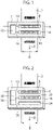
- a drying unit 1 for a web of printing material is shown, which reduces the relative humidity of the web of printing material 2 to a desired, adjustable value.
- the drying unit 1 is specifically designed so that the relative humidity of the printing material web 2 has a substantially constant value after the printing material web 2 has passed through the drying unit 1 and over the width B of the printing material web 2 .
- the drying unit 1 after figure 1 a sensor unit 6 in the form of a sensor bar, the measuring range of which extends over the entire width B of the printing material web 2 and measures the relative humidity or another measured variable from which the relative humidity of the printing material web 2 can be determined directly or indirectly.
- the sensor unit 6 according to the embodiment of Figure 1 and Figure 2 comprises a multiplicity of sensor elements 8 arranged next to one another, which each measure a defined section of the printing material web 2 .
- the sensor unit 6 can also include a single sensor element 8 or a number of sensor elements 8 which are/are arranged to traverse transversely to the transport direction x of the printing material web 2 .
- the sensor unit 6 is connected to an evaluation unit 10 via a data line 12, via which the measurement data of the sensor elements 8 are sent to the evaluation unit 10 and, if required, control commands can also be sent from the evaluation unit 10 or a control module (not shown) to the sensor unit 6 .
- evaluation unit 10 creates a profile of the relative humidity of printing material web 2 over width B of printing material web 2 and uses these values to determine an optimal setting for drying bar 4 in order to achieve the desired relative residual moisture content of printing material web B.
- the drying bar 4 also includes a number of drying elements 14 which are arranged next to one another and essentially over the entire width B of the printing material web 2 and are designed in such a way that they reduce the relative humidity of the printing material web 2 in a respectively assigned area.
- Each of these drying elements 12 can be controlled individually and the drying intensity can be adjusted individually, so that the desired target profile of the relative humidity can be optimally achieved from the determined actual profile of the relative humidity of the printing material web 2 by controlling the drying elements 12.
- the drying bar is also connected on the data side via a data line 16 to the evaluation unit 10 or to a control module of the evaluation unit 10 (not shown) in order to transmit control commands to the individual drying elements 12.
- the drying unit 1 can also include a moistening bar 18 .
- a moistening bar 18 Such a design of the drying unit 1 is in figure 2 shown.
- the moistening bar 18 also includes a number of moistening elements 20 next to one another, which are arranged essentially over the entire width B of the printing substrate web 2 and can moisten the printing substrate web 2 in a respectively assigned area, so that the relative humidity of the printing substrate web 2 is increased.
- This moistening unit 18 is also connected on the data side to the evaluation unit 10 via a data line 22 so that control signals can be transmitted from the evaluation unit 10 or a control module of the evaluation unit (not shown) to the moistening bar 18 .
- a drying bar 24 is provided in the transport direction x of the printing material web B after the moistening bar 18 or alternatively, not shown, before the moistening bar 18 in order to reduce the relative humidity of the printing material web to the desired target value.
- This drying strip 24 can also be used as in figure 1 shown include a number of individually controllable drying elements 14.
- a single drying element 14 can also be used, which extends over the width B of the printing material web 2.
- the drying bar 24 it is also connected to the evaluation unit 10 on the data side via a data line 26 .
Landscapes
- Engineering & Computer Science (AREA)
- Mechanical Engineering (AREA)
- Supply, Installation And Extraction Of Printed Sheets Or Plates (AREA)
- Ink Jet (AREA)
- Drying Of Solid Materials (AREA)
Description
Die Erfindung betrifft ein Verfahren zur Änderung der relativen Feuchte eines Bedruckstoffs mittels einer Trocknungseinheit, die eine Anzahl von Trocknungselementen umfasst, die quer zur Transportrichtung des Bedruckstoffs angeordnet sind und auf den Bedruckstoff gerichtet sind, um diesen jeweils mit einer Trocknungsintensität zu trocknen, wobei die Trocknungselemente einzeln angesteuert werden können und einer Befeuchtungseinrichtung, die eine Anzahl von Befeuchtungselementen umfasst, die quer zur Transportrichtung des Bedruckstoffs angeordnet sind und auf den Bedruckstoff gerichtet sind, um diesen jeweils mit einer Feuchtigkeitsmenge zu befeuchten, wobei die Befeuchtungselemente einzeln angesteuert werden können.The invention relates to a method for changing the relative humidity of a printing material by means of a drying unit which comprises a number of drying elements which are arranged transversely to the transport direction of the printing material and are directed towards the printing material in order to dry it with a drying intensity in each case, the drying elements can be controlled individually and a moistening device that includes a number of moistening elements that are arranged transversely to the transport direction of the printing material and are directed towards the printing material in order to moisten it with a quantity of moisture, it being possible for the moistening elements to be controlled individually.
Bei Digitaldruckmaschinen, die insbesondere nach dem Inkjet-Druckverfahren arbeiten, werden mit der Farbe relativ hohe Mengen an Flüssigkeit auf den Bedruckstoff aufgetragen und dringen in diesen ein, was insbesondere bei größeren Einträgen von Wasser als Lösemittel der Druckfarbe in Papier zu Problemen führen kann. Dabei sind insbesondere die Ausdehnung des Papiers sowohl in Längsrichtung als auch quer zur Faserrichtung, das Bilden von sogenannten Wassersäcken, d.h. durch die Dehnung verursachte Längung und die Veränderung der mechanischen Eigenschaften des Papiers zu beachten. Dies führt im Laufe der weiteren Verarbeitung des Bedruckstoffs zu Problemen und damit auch Qualitätseinbußen im Endprodukt und beispielsweise zum Verwerfen des Bedruckstoffs bei einem in Bedruckstoffrichtung gesehenen asymmetrischen bzw. ungleichen Farbauftrag aufgrund von sehr hoher Welligkeit des Papiers.In the case of digital printing machines, which in particular work according to the inkjet printing process, relatively large amounts of liquid are applied to the printing material with the ink and penetrate into it, which can lead to problems, especially if larger amounts of water are used as a solvent for the printing ink in the paper. In particular, the expansion of the paper both in the longitudinal direction and transverse to the fiber direction, the formation of so-called water pockets, i.e. the elongation caused by the stretching and the change in the mechanical properties of the paper must be taken into account. In the course of further processing of the printing material, this leads to problems and thus also to loss of quality in the end product and, for example, to warping of the printing material if the ink application is asymmetrical or uneven when viewed in the direction of the printing material due to very high paper waviness.
Durch die Feuchtigkeit kann sowohl der Druckprozess als auch der nachgeschaltete Nachverarbeitungsprozess beeinflusst werden. In der Nachverarbeitung führt dies beispielsweise zu der Problematik, dass sich das Papier entweder extrem unterschiedlich bezüglich der Elektrostatik verhält oder sehr wellig ist. Es kann aber auch ein Problem sein, dass aufgrund der teilweise hohen Feuchtigkeit des Papiers keine Elektrostatik beispielsweise zum Verblocken aufeinander liegender Blätter oder Signaturen verwendet werden, da die Elektrostatik bei höherer Bedruckstoffdichte abgeführt wird.The moisture can affect both the printing process and the downstream post-processing. In post-processing, for example, this leads to the problem that the paper either behaves extremely differently in terms of electrostatics or is very wavy. However, it can also be a problem that, due to the sometimes high moisture content of the paper, no electrostatics are used, for example to block sheets or signatures lying on top of one another, since the electrostatics are dissipated with higher printing material density.
Um die Feuchtigkeit des Bedruckstoffs zu reduzieren, werden im Stand der Technik daher Trocknungseinheiten eingesetzt, die mittels Heizelementen den Bedruckstoff trocknen.In order to reduce the moisture in the printing material, drying units are therefore used in the prior art, which dry the printing material by means of heating elements.
Aus der Druckschrift
Eine derartige Vorrichtung kann allerdings nicht verhindern, dass die Bedruckstoffbahn bzw. der Druck auch nach der Trocknung eine ungleichmäßige Feuchtigkeitsverteilung aufweist. Je nach Ausgangsfeuchte kann es dabei allerdings auch bei der Druckschrift
Aus den Druckschriften
Der Erfindung liegt daher insbesondere ausgehend von der Druckschrift
Diese Aufgabe wird erfindungsgemäß gelöst, indem mindestens zwei Trocknungselemente derart angesteuert werden, dass mindestens zwei Bereiche quer zur Transportrichtung des Bedruckstoffs mit einer unterschiedlichen Trocknungsintensität beaufschlagt werden und mindestens zwei Befeuchtungselemente derart angesteuert werden, dass mindestens zwei Bereiche quer zur Transportrichtung des Bedruckstoffs mit einer unterschiedlichen Feuchtigkeitsmenge beaufschlagt werden.This object is achieved according to the invention in that at least two drying elements are controlled in such a way that at least two areas transverse to the transport direction of the printing material are subjected to a different drying intensity and at least two moistening elements are controlled in such a way that at least two areas transverse to the transport direction of the printing material are subjected to a different amount of moisture be applied.
Die Erfindung geht von der Überlegung aus, dass der Eintrag von Lösemittel/Wasser vom Farbauftrag abhängig ist. Da auch die Farbe nicht gleichmäßig aufgetragen wird, ist auch die Feuchtigkeit nicht gleichmäßig auf den Bedruckstoff verteilt, sondern verändert sich sowohl in Bedruckstoffrichtung als auch quer dazu und ist üblicherweise in beiden Richtungen inhomogen. Es wurde dabei erkannt, dass bei gleicher Trocknungsdauer die Bereiche hoher Feuchtigkeit stärker getrocknet werden müssen, als die Bereiche geringerer Feuchtigkeit und die Bereiche geringerer Feuchtigkeit vor oder nach dem Trocknen entsprechend stärker befeuchtet werden müssen. Aus diesem Grund werden die mehreren quer zur Bedruckstoffrichtung angeordneten Trocknungselemente oder Befeuchtungselemente derart eingestellt, dass die Trocknungsintensität, also die bereitgestellte Temperatur zur Trocknung, bzw. Befeuchtungsintensität, also die Feuchtigkeitsmenge, variiert. Dabei sind mindestens zwei Bereiche bzw. Zonen quer zur Bedruckstoffrichtung vorgesehen, die mit einer unterschiedlichen Trocknungs- bzw. Befeuchtungsintensität beaufschlagt werden.The invention is based on the idea that the entry of solvents/water depends on the paint application. Since the ink is not applied evenly either, the moisture is not evenly distributed on the printing material, but changes both in the direction of the printing material and transversely to it and is usually inhomogeneous in both directions. It was recognized that for the same drying time, the areas of high moisture must be dried more than the areas of lower moisture and the areas of lower moisture must be moistened to a correspondingly greater extent before or after drying. For this reason, the several drying elements or moistening elements arranged transversely to the direction of the printing material are adjusted in such a way that the drying intensity, ie the temperature provided for drying, or moistening intensity, ie the amount of moisture, varies. At least two areas or zones are provided transversely to the direction of the printing material, which are subjected to different drying or moistening intensities.
Für eine optimale Trocknung des Bedruckstoffs bzw. eine möglichst konstante Restfeuchtigkeit des Bedruckstoffs wird in besonders bevorzugter Ausführung die Steuerung der Trocknungselemente bzw. der Befeuchtungselemente auf Basis von Messdaten einer Sensoreinheit vorgenommen. Dabei wird in bevorzugter Ausgestaltung die relative Feuchte des Bedruckstoffs bestimmt. Dabei kann die Sensoreinheit ebenfalls aus einer Anzahl von Sensorelementen bestehen, die quer zur Transportrichtung des Bedruckstoffs angeordnet sind. Die Sensorelemente messen dabei die relative Feuchte eines einzelnen Bereiches des Bedruckstoffs. Eine Steuereinheit kann anschließend auf Basis der Messdaten jedes einzelnen Bereiches, das diesen Bereich zugeordneten Trocknungs- oder Befeuchtungselement ansteuern und die optimale Trocknungsintensität bzw. Feuchtigkeitsmenge bestimmen, damit die Bedruckstoffbahn anschließend quer zur Transportrichtung eine im Wesentlichen konstante Verteilung der relativen Feuchte aufweist.In a particularly preferred embodiment, the drying elements or the moistening elements are controlled on the basis of measured data from a sensor unit for optimum drying of the printing material or for the residual moisture content of the printing material to be as constant as possible. In a preferred embodiment, the relative humidity of the printing material is determined. The sensor unit can also consist of a number of sensor elements that are arranged transversely to the transport direction of the printing material. The sensor elements measure the relative humidity of a single area of the printing material. Based on the measurement data of each individual area, a control unit can then control the drying or moistening element assigned to this area and determine the optimal drying intensity or amount of moisture, so that the printing material web then has a substantially constant distribution of relative moisture transversely to the transport direction.
Neben der Sensoreinheit zur Messung der relativen Feuchte, kann auch die Welligkeit der Bahn detektiert werden und aus ihr die Feuchtigkeit indirekt bestimmt werden. Da beim Inkjet-Verfahren der Lösemittel-/Wasser-Eintrag vom Sujet abhängig ist, sind die Stellen hoher Feuchtigkeit mit den Stellen einer hohen Farbbelegung gleichzusetzen. Somit können als Sensorelemente auch optische Sensoren zur Erfassung der Stellen unterschiedlicher Farbbelegung zum Einsatz kommen.In addition to the sensor unit for measuring the relative humidity, the waviness of the web can also be detected and the humidity can be indirectly determined from it. Since the solvent/water entry in the inkjet process depends on the subject, the areas of high moisture are to be equated with areas of high ink coverage. Thus, optical sensors can also be used as sensor elements for detecting the locations with different color assignments.
Aufgrund des direkten Zusammenhangs zwischen Farbbelegung und Feuchtigkeit bzw. Feuchtigkeitseintrag können die Bereiche hoher Feuchtigkeit auch aus den Druckdaten bzw. Vorstufendaten generiert werden, da Stellen mit hoher Farbbelegung einem hohen Feuchtigkeitsauftrag, Stellen mit mittlerer Farbbelegung einem mittleren Feuchtigkeitsauftrag und Stellen mit geringer Farbbelegung einem geringeren Feuchtigkeitsauftrag etc. entsprechen. Aus diesem Grund wird in alternativer oder zusätzlicher vorteilhafter Ausgestaltung die Steuerung der Trocknungselemente bzw. der Befeuchtungselemente auf Basis von hinterlegten oder eingegebenen Druckdaten oder Vorstufendaten vorgenommen. Dabei kann zusätzlich die Bedruckstoffgeschwindigkeit und der Weg des Bedruckstoffs berücksichtigt werden, um eine zeitlich optimal abgestimmte Steuerung der Trocknungselemente bzw. Befeuchtungselemente zu erreichen.Due to the direct relationship between ink coverage and moisture or moisture entry, the areas of high moisture can also be generated from the print data or prepress data, since areas with high ink coverage have a high moisture application, areas with a medium ink coverage have a medium moisture application and areas with a low ink coverage have a lower moisture application etc. correspond. For this reason, in an alternative or additional advantageous embodiment, the drying elements or the moistening elements are controlled on the basis of stored or input print data or preliminary stage data. In this case, the printing material speed and the path of the printing material can also be taken into account in order to achieve optimally timed control of the drying elements or moistening elements.
Um eine Veränderung der Farbbelegung in Transportrichtung des Bedruckstoffs zu berücksichtigen, werden in bevorzugter Ausführung die Trocknungselemente bzw. Befeuchtungselemente auch derart angesteuert, dass mindestens zwei Bereiche in Transportrichtung des Bedruckstoffs mit einer unterschiedlichen Trocknungsintensität bzw. Feuchtigkeitsmenge beaufschlagt werden.In order to take into account a change in the ink coverage in the transport direction of the printing material, in a preferred embodiment the drying elements or moistening elements are also controlled in such a way that at least two areas in the transport direction of the printing material are subjected to a different drying intensity or amount of moisture.
Die mit der Erfindung erzielten Vorteile bestehen insbesondere darin, dass durch die unterschiedliche Trocknung bzw. Befeuchtung einzelner Bereiche quer zur oder auch in Transportrichtung des Bedruckstoffs, die im Rahmen des Druckprozesses inhomogene relative Feuchte des Bedruckstoffs ausgeglichen werden kann. Dadurch wird eine im Wesentlichen gleichmäßige und konstante Verteilung der relativen Feuchte erreicht. Auch kann durch die individuelle Steuerung der Trocknungs- und Befeuchtungselemente eine gewünschte und für die weitere Verarbeitung optimale Restfeuchtigkeit des Bedruckstoffs erreicht werden.The advantages achieved with the invention are in particular that the different drying or moistening of individual areas transverse to or in the transport direction of the printing material, the inhomogeneous relative humidity of the printing material can be compensated during the printing process. This achieves an essentially uniform and constant distribution of the relative humidity. Individual control of the drying and moistening elements can also achieve a desired residual moisture level in the printing material that is optimal for further processing.
Ein Ausführungsbeispiel einer Erfindung wird anhand einer Zeichnung näher erläutert. Darin zeigen:
Figur 1- eine Trocknungseinheit mit einer Sensorleiste und einer Trocknungsleiste,
Figur 2- eine Trocknungseinheit mit einer zusätzlichen Befeuchtungsleiste.
- figure 1
- a drying unit with a sensor bar and a drying bar,
- figure 2
- a drying unit with an additional moistening bar.
Gleiche Teile sind in allen Figuren mit denselben Bezugszeichen versehen.Identical parts are provided with the same reference symbols in all figures.
In
Neben einer Trocknungsleiste 4 weist die Trocknungseinheit 1 nach der
Die Auswerteeinheit 10 erstellt aus den Messdaten ein Profil der relativen Feuchte der Bedruckstoffbahn 2 über die Breite B der Bedruckstoffbahn 2 und ermittelt aus diesen Werten eine optimale Einstellung für die Trocknungsleiste 4, um die gewünschte relative Restfeuchte der Bedruckstoffbahn B zu erzielen. Die Trocknungsleiste 4 umfasst dazu ebenfalls eine Anzahl von Trocknungselementen 14, die nebeneinander und im Wesentlichen über die gesamte Breite B der Bedruckstoffbahn 2 angeordnet sind und derart ausgebildet sind, dass sie die relative Feuchte der Bedruckstoffbahn 2 in einem jeweils zugeordneten Bereich senken. Jedes dieser Trocknungselemente 12 kann dabei einzeln angesteuert werden und die Trocknungsintensität einzeln eingestellt werden, sodass in optimaler Art und Weise aus dem ermittelten Ist-Profil der relativen Feuchte der Bedruckstoffbahn 2, das gewünschte Zielprofil der relativen Feuchte durch Ansteuerung der Trocknungselemente 12 erreicht werden kann. Dazu ist die Trocknungsleiste datenseitig ebenfalls über eine Datenleitung 16 mit der Auswerteeinheit 10 bzw. einem nicht dargestellten Steuermodul der Auswerteeinheit 10 verbunden, um Steuerbefehle an die einzelnen Trocknungselemente 12 zu übertragen.From the measurement data,
Mit einer derartigen Trocknungseinheit 1 ist es somit möglich eine unterschiedliche Verteilung der relativen Feuchte einer Bedruckstoffbahn 2 (dargestellt durch eine unterschiedlich intensive Grauschattierung auf der Bedruckstoffbahn 2) in Abhängigkeit der relativen Feuchte zu trocknen, sodass eine homogene relative Restfeuchteverteilung der Bedruckstoffbahn 2 erzielt werden kann.With such a
In alternativer oder zusätzlicher Ausführung kann die Trocknungseinheit 1 auch eine Befeuchtungsleiste 18 umfassen. Eine derartige Ausgestaltung der Trocknungseinheit 1 ist in
Auch die Befeuchtungsleiste 18 umfasst eine Anzahl von nebeneinander liegenden Befeuchtungselementen 20, die im Wesentlichen über die gesamte Breite B der Bedruckstoffbahn 2 angeordnet sind und die Bedruckstoffbahn 2 in einem jeweils zugeordneten Bereich befeuchten kann, so dass die relative Feuchte der Bedruckstoffbahn 2 erhöht wird. Auch diese Befeuchtungseinheit 18 ist datenseitig mit der Auswerteeinheit 10 über eine Datenleitung 22 verbunden, sodass Steuersignale von der Auswerteeinheit 10 bzw. einem nicht dargestellten Steuermodul der Auswerteeinheit an die Befeuchtungsleiste 18 übertragen werden können.The moistening
Im Unterschied zu der Trocknungseinheit 1 nach
- 11
- Trocknungseinheitdrying unit
- 22
- Bedruckstoffbahnsubstrate web
- 44
- Trocknungsleistedrying bar
- 66
- Sensoreinheitsensor unit
- 88th
- Sensorelementsensor element
- 1010
- Auswerteeinheitevaluation unit
- 1212
- Datenleitungdata line
- 1414
- Trocknungselementdrying element
- 1616
- Datenleitungdata line
- 1818
- Befeuchtungsleistehumidification bar
- 2020
- Befeuchtungselementhumidification element
- 2222
- Datenleitungdata line
- 2424
- Trocknungsleistedrying bar
- BB
- Breite der BedruckstoffbahnWidth of the printing substrate
- xx
- Transportrichtung der BedruckstoffbahnTransport direction of the printing substrate
Claims (5)
- A method for changing the relative dampness of a printing material (2) by means of a dampener (18), wherein the printing material is printed upstream of the dampener (18) and upstream of a drying unit (1) by means of a digital printing press operating in the inkjet printing process, wherein the dampener (18) comprises a plurality of dampening elements (20), which are arranged transversely to the transport direction (x) of the printing material (2) and are directed to the printing material (2) in order to dampen the latter in each case with a moisture quantity, wherein the dampening elements (20) can be controlled individually,wherein at least two dampening elements (20) are controlled in such a way that a different moisture quantity is applied to at least two areas transversely to the transport direction (x) of the printing material (2),wherein
the drying unit (1) comprises a plurality of drying elements (14), which are arranged transversely to the transport direction (x) of the printing material (2) and are directed to the printing material (2) in order to dry the latter in each case with a drying intensity, wherein the drying elements (14) can be controlled individually,wherein at least two drying elements (14) is controlled in such a way that a different drying intensity is applied to at least two areas transversely to the transport direction (x) of the printing material (2). - The method for changing the relative dampness of a printing material (2) according to claim 1, characterized in that the control of the drying elements (14) and/or of the dampening elements (20) is carried out on the basis of measurement data from a sensor unit (6) .
- The method for changing the relative dampness of a printing material (2) according to claim 2, characterized in that the sensor unit (6) measures the relative dampness of the printing material web (2).
- The method for changing the relative dampness of a printing material (2) according to claim 1, characterized in that the control of the drying elements (14) and/or of the dampening elements (20) is carried out on the basis of stored or input printing data or prepress data.
- The method for changing the relative dampness of a printing material (2) according to one of claims 1 to 4, characterized in that the drying elements (14) and/or dampening elements (20) are controlled in such a way that a different drying intensity or moisture quantity, respectively, is applied to at least two areas in the transport direction (x) of the printing material (2).
Applications Claiming Priority (1)
| Application Number | Priority Date | Filing Date | Title |
|---|---|---|---|
| DE102015104382.3A DE102015104382A1 (en) | 2015-03-24 | 2015-03-24 | Process for the controlled and controlled rewetting and drying of paper webs |
Publications (3)
| Publication Number | Publication Date |
|---|---|
| EP3072700A1 EP3072700A1 (en) | 2016-09-28 |
| EP3072700B1 EP3072700B1 (en) | 2019-05-08 |
| EP3072700B2 true EP3072700B2 (en) | 2022-08-17 |
Family
ID=55646299
Family Applications (1)
| Application Number | Title | Priority Date | Filing Date |
|---|---|---|---|
| EP16160471.5A Active EP3072700B2 (en) | 2015-03-24 | 2016-03-15 | Method for the regulated and controlled re-dampening and drying of paper webs |
Country Status (3)
| Country | Link |
|---|---|
| EP (1) | EP3072700B2 (en) |
| JP (1) | JP2016180581A (en) |
| DE (1) | DE102015104382A1 (en) |
Families Citing this family (10)
| Publication number | Priority date | Publication date | Assignee | Title |
|---|---|---|---|---|
| DE102015222753B4 (en) | 2015-11-18 | 2019-02-28 | Koenig & Bauer Ag | Flat material processing apparatus and a method of processing a flat material |
| DE102016109934A1 (en) * | 2016-05-30 | 2017-11-30 | grapho metronic Meß- und Regeltechnik GmbH | Control of inline aggregates in a printing machine |
| CN106864023B (en) * | 2017-02-20 | 2019-03-15 | 贵阳精彩数字印刷有限公司 | Baker is used in a kind of printing |
| CN107471823A (en) * | 2017-08-30 | 2017-12-15 | 张家港保税区美佳印刷有限公司 | A kind of humidification device of paper printing matter |
| DE102019206973A1 (en) * | 2018-06-14 | 2019-12-19 | Heidelberger Druckmaschinen Ag | Sheet printing machine with a dampening device |
| DE102020128178A1 (en) * | 2019-11-29 | 2021-06-02 | Heidelberger Druckmaschinen Aktiengesellschaft | Method for drying a printed substrate using a thermodynamic model |
| EP3960479B8 (en) * | 2020-08-24 | 2023-07-12 | SWISS KRONO Tec AG | Method for printing the surface of a workpiece with decoration and device therefor |
| DE102020128616A1 (en) | 2020-10-30 | 2022-05-05 | Canon Production Printing Holding B.V. | Device and method for printing a printing material with a printing device |
| DE102022105332A1 (en) | 2022-03-08 | 2023-09-14 | Koenig & Bauer Ag | Printing machine with at least one creasing tool |
| DE102022105333A1 (en) | 2022-03-08 | 2023-09-14 | Koenig & Bauer Ag | Method for mechanically introducing at least one crease into a web-shaped or sheet-shaped printed printing material |
Citations (2)
| Publication number | Priority date | Publication date | Assignee | Title |
|---|---|---|---|---|
| EP1306223A2 (en) † | 2001-10-26 | 2003-05-02 | Hewlett-Packard Company | A printer having precision ink drying capability and method of assembling the printer |
| US20140366760A1 (en) † | 2013-06-18 | 2014-12-18 | Stuart J. Boland | Liquid dispersal in radiant dryers for printing systems |
Family Cites Families (7)
| Publication number | Priority date | Publication date | Assignee | Title |
|---|---|---|---|---|
| US5592751A (en) | 1994-11-23 | 1997-01-14 | Voith Sulzer Papiermaschinen Gmbh | Dryer section having combination of single and double tier dryer groups |
| DE19533673A1 (en) * | 1995-09-13 | 1997-03-20 | Tech Uni Chemnitz Zwickau I Fu | Process for drying and re-moistening printed sheet and/or web material |
| DE29622903U1 (en) * | 1996-01-31 | 1997-07-17 | Waizmann Franz | Dryer in a printing press |
| DE19901801C2 (en) * | 1999-01-19 | 2003-12-11 | Baldwin Germany Gmbh | Device for conditioning a paper web |
| FI124614B (en) | 2005-07-20 | 2014-11-14 | Stora Enso Oyj | Method for drying a moving web of material in a paper or cardboard machine |
| EP2258553A1 (en) * | 2009-06-05 | 2010-12-08 | WIFAG Maschinenfabrik AG | Device and method for drying paint on a printed substrate |
| CN104487258B (en) | 2012-09-21 | 2017-03-08 | 惠普发展公司,有限责任合伙企业 | Dry component |
-
2015
- 2015-03-24 DE DE102015104382.3A patent/DE102015104382A1/en active Pending
-
2016
- 2016-03-04 JP JP2016041907A patent/JP2016180581A/en active Pending
- 2016-03-15 EP EP16160471.5A patent/EP3072700B2/en active Active
Patent Citations (2)
| Publication number | Priority date | Publication date | Assignee | Title |
|---|---|---|---|---|
| EP1306223A2 (en) † | 2001-10-26 | 2003-05-02 | Hewlett-Packard Company | A printer having precision ink drying capability and method of assembling the printer |
| US20140366760A1 (en) † | 2013-06-18 | 2014-12-18 | Stuart J. Boland | Liquid dispersal in radiant dryers for printing systems |
Also Published As
| Publication number | Publication date |
|---|---|
| JP2016180581A (en) | 2016-10-13 |
| EP3072700B1 (en) | 2019-05-08 |
| EP3072700A1 (en) | 2016-09-28 |
| DE102015104382A1 (en) | 2016-09-29 |
Similar Documents
| Publication | Publication Date | Title |
|---|---|---|
| EP3072700B2 (en) | Method for the regulated and controlled re-dampening and drying of paper webs | |
| EP3006216A2 (en) | Method for compensating local registration inaccuracies | |
| DE102010060409A1 (en) | Method for reducing the wave formation of a printing substrate in a printer and device for printing on a printing substrate | |
| EP4200584A1 (en) | Method for printing a decoration, and apparatus therefor | |
| EP2293947B1 (en) | Use of a printing paper printed with a pattern for sheetlike components | |
| EP2927003B1 (en) | Wood material board production assembly and method for manufacturing a wood material board | |
| EP3574144B1 (en) | Curtain coater and process for application of an application medium | |
| DE102018117699A1 (en) | Method and device for printing on both sides of a record carrier | |
| DE102017202665A1 (en) | Method of inkjet printing | |
| EP0634271B1 (en) | Method and device for adjusting the temperature of an ink in the inking unit of a printing machine | |
| WO2008145447A1 (en) | Method and device for moistening a material web | |
| EP2206605B2 (en) | Printer and method for printing on paper | |
| DE102019103703B4 (en) | Device and method for coating and computer program product | |
| DE60214380T3 (en) | METHOD AND DEVICE FOR CONTROLLING DRYING IN THE FIBER DRYER | |
| EP0924075B1 (en) | Device and method for avoiding the production of condensation water in printing presses | |
| EP3960479B1 (en) | Method for printing the surface of a workpiece with decoration and device therefor | |
| DE4402338B4 (en) | Method for controlling geometric changes of a printing material in an operation of printing and drying a printed image | |
| DE10159999B4 (en) | Process and apparatus for solvent extraction from printed paper | |
| DE102019100884A1 (en) | Device and method for treating a fibrous web | |
| WO2004025023A1 (en) | Device and method for producing and/or treating a fibrous strip | |
| DE102008049547B4 (en) | Method and device for powdering printed sheets | |
| DE102009030878A1 (en) | Offset printing process | |
| DE112007002214B4 (en) | Method and apparatus for controlling the drying of a heat-sensitive, coated or surface-sized fibrous web | |
| DE102014103375B3 (en) | Method and device for printing on a substrate with adaptation of the electrical resistance of the printing substrate | |
| EP4272966A1 (en) | Method of printing a paper and digital printing device comprising means for reducing condensate formation |
Legal Events
| Date | Code | Title | Description |
|---|---|---|---|
| PUAI | Public reference made under article 153(3) epc to a published international application that has entered the european phase |
Free format text: ORIGINAL CODE: 0009012 |
|
| AK | Designated contracting states |
Kind code of ref document: A1 Designated state(s): AL AT BE BG CH CY CZ DE DK EE ES FI FR GB GR HR HU IE IS IT LI LT LU LV MC MK MT NL NO PL PT RO RS SE SI SK SM TR |
|
| AX | Request for extension of the european patent |
Extension state: BA ME |
|
| STAA | Information on the status of an ep patent application or granted ep patent |
Free format text: STATUS: REQUEST FOR EXAMINATION WAS MADE |
|
| 17P | Request for examination filed |
Effective date: 20170328 |
|
| RBV | Designated contracting states (corrected) |
Designated state(s): AL AT BE BG CH CY CZ DE DK EE ES FI FR GB GR HR HU IE IS IT LI LT LU LV MC MK MT NL NO PL PT RO RS SE SI SK SM TR |
|
| RAP1 | Party data changed (applicant data changed or rights of an application transferred) |
Owner name: MANROLAND GOSS WEB SYSTEMS GMBH |
|
| GRAP | Despatch of communication of intention to grant a patent |
Free format text: ORIGINAL CODE: EPIDOSNIGR1 |
|
| STAA | Information on the status of an ep patent application or granted ep patent |
Free format text: STATUS: GRANT OF PATENT IS INTENDED |
|
| INTG | Intention to grant announced |
Effective date: 20181109 |
|
| GRAS | Grant fee paid |
Free format text: ORIGINAL CODE: EPIDOSNIGR3 |
|
| GRAA | (expected) grant |
Free format text: ORIGINAL CODE: 0009210 |
|
| STAA | Information on the status of an ep patent application or granted ep patent |
Free format text: STATUS: THE PATENT HAS BEEN GRANTED |
|
| AK | Designated contracting states |
Kind code of ref document: B1 Designated state(s): AL AT BE BG CH CY CZ DE DK EE ES FI FR GB GR HR HU IE IS IT LI LT LU LV MC MK MT NL NO PL PT RO RS SE SI SK SM TR |
|
| REG | Reference to a national code |
Ref country code: GB Ref legal event code: FG4D Free format text: NOT ENGLISH |
|
| REG | Reference to a national code |
Ref country code: CH Ref legal event code: EP Ref country code: AT Ref legal event code: REF Ref document number: 1129539 Country of ref document: AT Kind code of ref document: T Effective date: 20190515 |
|
| REG | Reference to a national code |
Ref country code: DE Ref legal event code: R096 Ref document number: 502016004510 Country of ref document: DE Ref country code: IE Ref legal event code: FG4D Free format text: LANGUAGE OF EP DOCUMENT: GERMAN |
|
| REG | Reference to a national code |
Ref country code: NL Ref legal event code: MP Effective date: 20190508 |
|
| REG | Reference to a national code |
Ref country code: LT Ref legal event code: MG4D |
|
| PG25 | Lapsed in a contracting state [announced via postgrant information from national office to epo] |
Ref country code: SE Free format text: LAPSE BECAUSE OF FAILURE TO SUBMIT A TRANSLATION OF THE DESCRIPTION OR TO PAY THE FEE WITHIN THE PRESCRIBED TIME-LIMIT Effective date: 20190508 Ref country code: NL Free format text: LAPSE BECAUSE OF FAILURE TO SUBMIT A TRANSLATION OF THE DESCRIPTION OR TO PAY THE FEE WITHIN THE PRESCRIBED TIME-LIMIT Effective date: 20190508 Ref country code: HR Free format text: LAPSE BECAUSE OF FAILURE TO SUBMIT A TRANSLATION OF THE DESCRIPTION OR TO PAY THE FEE WITHIN THE PRESCRIBED TIME-LIMIT Effective date: 20190508 Ref country code: LT Free format text: LAPSE BECAUSE OF FAILURE TO SUBMIT A TRANSLATION OF THE DESCRIPTION OR TO PAY THE FEE WITHIN THE PRESCRIBED TIME-LIMIT Effective date: 20190508 Ref country code: ES Free format text: LAPSE BECAUSE OF FAILURE TO SUBMIT A TRANSLATION OF THE DESCRIPTION OR TO PAY THE FEE WITHIN THE PRESCRIBED TIME-LIMIT Effective date: 20190508 Ref country code: FI Free format text: LAPSE BECAUSE OF FAILURE TO SUBMIT A TRANSLATION OF THE DESCRIPTION OR TO PAY THE FEE WITHIN THE PRESCRIBED TIME-LIMIT Effective date: 20190508 Ref country code: NO Free format text: LAPSE BECAUSE OF FAILURE TO SUBMIT A TRANSLATION OF THE DESCRIPTION OR TO PAY THE FEE WITHIN THE PRESCRIBED TIME-LIMIT Effective date: 20190808 Ref country code: PT Free format text: LAPSE BECAUSE OF FAILURE TO SUBMIT A TRANSLATION OF THE DESCRIPTION OR TO PAY THE FEE WITHIN THE PRESCRIBED TIME-LIMIT Effective date: 20190908 Ref country code: AL Free format text: LAPSE BECAUSE OF FAILURE TO SUBMIT A TRANSLATION OF THE DESCRIPTION OR TO PAY THE FEE WITHIN THE PRESCRIBED TIME-LIMIT Effective date: 20190508 |
|
| PG25 | Lapsed in a contracting state [announced via postgrant information from national office to epo] |
Ref country code: GR Free format text: LAPSE BECAUSE OF FAILURE TO SUBMIT A TRANSLATION OF THE DESCRIPTION OR TO PAY THE FEE WITHIN THE PRESCRIBED TIME-LIMIT Effective date: 20190809 Ref country code: LV Free format text: LAPSE BECAUSE OF FAILURE TO SUBMIT A TRANSLATION OF THE DESCRIPTION OR TO PAY THE FEE WITHIN THE PRESCRIBED TIME-LIMIT Effective date: 20190508 Ref country code: RS Free format text: LAPSE BECAUSE OF FAILURE TO SUBMIT A TRANSLATION OF THE DESCRIPTION OR TO PAY THE FEE WITHIN THE PRESCRIBED TIME-LIMIT Effective date: 20190508 Ref country code: BG Free format text: LAPSE BECAUSE OF FAILURE TO SUBMIT A TRANSLATION OF THE DESCRIPTION OR TO PAY THE FEE WITHIN THE PRESCRIBED TIME-LIMIT Effective date: 20190808 |
|
| PG25 | Lapsed in a contracting state [announced via postgrant information from national office to epo] |
Ref country code: EE Free format text: LAPSE BECAUSE OF FAILURE TO SUBMIT A TRANSLATION OF THE DESCRIPTION OR TO PAY THE FEE WITHIN THE PRESCRIBED TIME-LIMIT Effective date: 20190508 Ref country code: CZ Free format text: LAPSE BECAUSE OF FAILURE TO SUBMIT A TRANSLATION OF THE DESCRIPTION OR TO PAY THE FEE WITHIN THE PRESCRIBED TIME-LIMIT Effective date: 20190508 Ref country code: RO Free format text: LAPSE BECAUSE OF FAILURE TO SUBMIT A TRANSLATION OF THE DESCRIPTION OR TO PAY THE FEE WITHIN THE PRESCRIBED TIME-LIMIT Effective date: 20190508 Ref country code: SK Free format text: LAPSE BECAUSE OF FAILURE TO SUBMIT A TRANSLATION OF THE DESCRIPTION OR TO PAY THE FEE WITHIN THE PRESCRIBED TIME-LIMIT Effective date: 20190508 Ref country code: DK Free format text: LAPSE BECAUSE OF FAILURE TO SUBMIT A TRANSLATION OF THE DESCRIPTION OR TO PAY THE FEE WITHIN THE PRESCRIBED TIME-LIMIT Effective date: 20190508 |
|
| REG | Reference to a national code |
Ref country code: DE Ref legal event code: R026 Ref document number: 502016004510 Country of ref document: DE |
|
| PLBI | Opposition filed |
Free format text: ORIGINAL CODE: 0009260 |
|
| PLAX | Notice of opposition and request to file observation + time limit sent |
Free format text: ORIGINAL CODE: EPIDOSNOBS2 |
|
| PG25 | Lapsed in a contracting state [announced via postgrant information from national office to epo] |
Ref country code: SM Free format text: LAPSE BECAUSE OF FAILURE TO SUBMIT A TRANSLATION OF THE DESCRIPTION OR TO PAY THE FEE WITHIN THE PRESCRIBED TIME-LIMIT Effective date: 20190508 Ref country code: IT Free format text: LAPSE BECAUSE OF FAILURE TO SUBMIT A TRANSLATION OF THE DESCRIPTION OR TO PAY THE FEE WITHIN THE PRESCRIBED TIME-LIMIT Effective date: 20190508 |
|
| 26 | Opposition filed |
Opponent name: KOENIG & BAUER AG Effective date: 20200207 |
|
| PG25 | Lapsed in a contracting state [announced via postgrant information from national office to epo] |
Ref country code: TR Free format text: LAPSE BECAUSE OF FAILURE TO SUBMIT A TRANSLATION OF THE DESCRIPTION OR TO PAY THE FEE WITHIN THE PRESCRIBED TIME-LIMIT Effective date: 20190508 |
|
| PG25 | Lapsed in a contracting state [announced via postgrant information from national office to epo] |
Ref country code: PL Free format text: LAPSE BECAUSE OF FAILURE TO SUBMIT A TRANSLATION OF THE DESCRIPTION OR TO PAY THE FEE WITHIN THE PRESCRIBED TIME-LIMIT Effective date: 20190508 |
|
| PG25 | Lapsed in a contracting state [announced via postgrant information from national office to epo] |
Ref country code: SI Free format text: LAPSE BECAUSE OF FAILURE TO SUBMIT A TRANSLATION OF THE DESCRIPTION OR TO PAY THE FEE WITHIN THE PRESCRIBED TIME-LIMIT Effective date: 20190508 |
|
| PLBB | Reply of patent proprietor to notice(s) of opposition received |
Free format text: ORIGINAL CODE: EPIDOSNOBS3 |
|
| PG25 | Lapsed in a contracting state [announced via postgrant information from national office to epo] |
Ref country code: MC Free format text: LAPSE BECAUSE OF FAILURE TO SUBMIT A TRANSLATION OF THE DESCRIPTION OR TO PAY THE FEE WITHIN THE PRESCRIBED TIME-LIMIT Effective date: 20190508 |
|
| REG | Reference to a national code |
Ref country code: CH Ref legal event code: PL |
|
| REG | Reference to a national code |
Ref country code: BE Ref legal event code: MM Effective date: 20200331 |
|
| PG25 | Lapsed in a contracting state [announced via postgrant information from national office to epo] |
Ref country code: LU Free format text: LAPSE BECAUSE OF NON-PAYMENT OF DUE FEES Effective date: 20200315 |
|
| PG25 | Lapsed in a contracting state [announced via postgrant information from national office to epo] |
Ref country code: LI Free format text: LAPSE BECAUSE OF NON-PAYMENT OF DUE FEES Effective date: 20200331 Ref country code: IE Free format text: LAPSE BECAUSE OF NON-PAYMENT OF DUE FEES Effective date: 20200315 Ref country code: FR Free format text: LAPSE BECAUSE OF NON-PAYMENT OF DUE FEES Effective date: 20200331 Ref country code: CH Free format text: LAPSE BECAUSE OF NON-PAYMENT OF DUE FEES Effective date: 20200331 |
|
| PG25 | Lapsed in a contracting state [announced via postgrant information from national office to epo] |
Ref country code: BE Free format text: LAPSE BECAUSE OF NON-PAYMENT OF DUE FEES Effective date: 20200331 |
|
| PLAB | Opposition data, opponent's data or that of the opponent's representative modified |
Free format text: ORIGINAL CODE: 0009299OPPO |
|
| GBPC | Gb: european patent ceased through non-payment of renewal fee |
Effective date: 20200315 |
|
| R26 | Opposition filed (corrected) |
Opponent name: KOENIG & BAUER AG Effective date: 20200207 |
|
| PG25 | Lapsed in a contracting state [announced via postgrant information from national office to epo] |
Ref country code: GB Free format text: LAPSE BECAUSE OF NON-PAYMENT OF DUE FEES Effective date: 20200315 |
|
| REG | Reference to a national code |
Ref country code: CH Ref legal event code: PK Free format text: TITEL Ref country code: CH Ref legal event code: PK Free format text: BERICHTIGUNGEN |
|
| RIC2 | Information provided on ipc code assigned after grant |
Ipc: B41F 23/02 20060101ALI20211130BHEP Ipc: B41F 33/02 20060101ALI20211130BHEP Ipc: B41F 23/04 20060101ALI20211130BHEP Ipc: B41J 11/00 20060101AFI20211130BHEP |
|
| REG | Reference to a national code |
Ref country code: AT Ref legal event code: MM01 Ref document number: 1129539 Country of ref document: AT Kind code of ref document: T Effective date: 20210315 |
|
| PG25 | Lapsed in a contracting state [announced via postgrant information from national office to epo] |
Ref country code: MT Free format text: LAPSE BECAUSE OF FAILURE TO SUBMIT A TRANSLATION OF THE DESCRIPTION OR TO PAY THE FEE WITHIN THE PRESCRIBED TIME-LIMIT Effective date: 20190508 Ref country code: CY Free format text: LAPSE BECAUSE OF FAILURE TO SUBMIT A TRANSLATION OF THE DESCRIPTION OR TO PAY THE FEE WITHIN THE PRESCRIBED TIME-LIMIT Effective date: 20190508 |
|
| PG25 | Lapsed in a contracting state [announced via postgrant information from national office to epo] |
Ref country code: MK Free format text: LAPSE BECAUSE OF FAILURE TO SUBMIT A TRANSLATION OF THE DESCRIPTION OR TO PAY THE FEE WITHIN THE PRESCRIBED TIME-LIMIT Effective date: 20190508 Ref country code: IS Free format text: LAPSE BECAUSE OF FAILURE TO SUBMIT A TRANSLATION OF THE DESCRIPTION OR TO PAY THE FEE WITHIN THE PRESCRIBED TIME-LIMIT Effective date: 20190908 |
|
| PUAH | Patent maintained in amended form |
Free format text: ORIGINAL CODE: 0009272 |
|
| STAA | Information on the status of an ep patent application or granted ep patent |
Free format text: STATUS: PATENT MAINTAINED AS AMENDED |
|
| 27A | Patent maintained in amended form |
Effective date: 20220817 |
|
| AK | Designated contracting states |
Kind code of ref document: B2 Designated state(s): AL AT BE BG CH CY CZ DE DK EE ES FI FR GB GR HR HU IE IS IT LI LT LU LV MC MK MT NL NO PL PT RO RS SE SI SK SM TR |
|
| REG | Reference to a national code |
Ref country code: DE Ref legal event code: R102 Ref document number: 502016004510 Country of ref document: DE |
|
| PG25 | Lapsed in a contracting state [announced via postgrant information from national office to epo] |
Ref country code: AT Free format text: LAPSE BECAUSE OF NON-PAYMENT OF DUE FEES Effective date: 20210315 |
|
| PGFP | Annual fee paid to national office [announced via postgrant information from national office to epo] |
Ref country code: DE Payment date: 20240320 Year of fee payment: 9 |