EP3072600A1 - Systems and methods for applying materials to interface areas - Google Patents
Systems and methods for applying materials to interface areas Download PDFInfo
- Publication number
- EP3072600A1 EP3072600A1 EP16159790.1A EP16159790A EP3072600A1 EP 3072600 A1 EP3072600 A1 EP 3072600A1 EP 16159790 A EP16159790 A EP 16159790A EP 3072600 A1 EP3072600 A1 EP 3072600A1
- Authority
- EP
- European Patent Office
- Prior art keywords
- inner guide
- housing
- applicator
- interface area
- fastener
- Prior art date
- Legal status (The legal status is an assumption and is not a legal conclusion. Google has not performed a legal analysis and makes no representation as to the accuracy of the status listed.)
- Granted
Links
Images








Classifications
-
- B—PERFORMING OPERATIONS; TRANSPORTING
- B64—AIRCRAFT; AVIATION; COSMONAUTICS
- B64F—GROUND OR AIRCRAFT-CARRIER-DECK INSTALLATIONS SPECIALLY ADAPTED FOR USE IN CONNECTION WITH AIRCRAFT; DESIGNING, MANUFACTURING, ASSEMBLING, CLEANING, MAINTAINING OR REPAIRING AIRCRAFT, NOT OTHERWISE PROVIDED FOR; HANDLING, TRANSPORTING, TESTING OR INSPECTING AIRCRAFT COMPONENTS, NOT OTHERWISE PROVIDED FOR
- B64F5/00—Designing, manufacturing, assembling, cleaning, maintaining or repairing aircraft, not otherwise provided for; Handling, transporting, testing or inspecting aircraft components, not otherwise provided for
-
- B—PERFORMING OPERATIONS; TRANSPORTING
- B05—SPRAYING OR ATOMISING IN GENERAL; APPLYING FLUENT MATERIALS TO SURFACES, IN GENERAL
- B05C—APPARATUS FOR APPLYING FLUENT MATERIALS TO SURFACES, IN GENERAL
- B05C11/00—Component parts, details or accessories not specifically provided for in groups B05C1/00 - B05C9/00
-
- B—PERFORMING OPERATIONS; TRANSPORTING
- B05—SPRAYING OR ATOMISING IN GENERAL; APPLYING FLUENT MATERIALS TO SURFACES, IN GENERAL
- B05C—APPARATUS FOR APPLYING FLUENT MATERIALS TO SURFACES, IN GENERAL
- B05C17/00—Hand tools or apparatus using hand held tools, for applying liquids or other fluent materials to, for spreading applied liquids or other fluent materials on, or for partially removing applied liquids or other fluent materials from, surfaces
- B05C17/005—Hand tools or apparatus using hand held tools, for applying liquids or other fluent materials to, for spreading applied liquids or other fluent materials on, or for partially removing applied liquids or other fluent materials from, surfaces for discharging material from a reservoir or container located in or on the hand tool through an outlet orifice by pressure without using surface contacting members like pads or brushes
- B05C17/015—Hand tools or apparatus using hand held tools, for applying liquids or other fluent materials to, for spreading applied liquids or other fluent materials on, or for partially removing applied liquids or other fluent materials from, surfaces for discharging material from a reservoir or container located in or on the hand tool through an outlet orifice by pressure without using surface contacting members like pads or brushes with pneumatically or hydraulically actuated piston or the like
-
- B—PERFORMING OPERATIONS; TRANSPORTING
- B05—SPRAYING OR ATOMISING IN GENERAL; APPLYING FLUENT MATERIALS TO SURFACES, IN GENERAL
- B05C—APPARATUS FOR APPLYING FLUENT MATERIALS TO SURFACES, IN GENERAL
- B05C5/00—Apparatus in which liquid or other fluent material is projected, poured or allowed to flow on to the surface of the work
- B05C5/02—Apparatus in which liquid or other fluent material is projected, poured or allowed to flow on to the surface of the work the liquid or other fluent material being discharged through an outlet orifice by pressure, e.g. from an outlet device in contact or almost in contact, with the work
-
- B—PERFORMING OPERATIONS; TRANSPORTING
- B05—SPRAYING OR ATOMISING IN GENERAL; APPLYING FLUENT MATERIALS TO SURFACES, IN GENERAL
- B05C—APPARATUS FOR APPLYING FLUENT MATERIALS TO SURFACES, IN GENERAL
- B05C5/00—Apparatus in which liquid or other fluent material is projected, poured or allowed to flow on to the surface of the work
- B05C5/02—Apparatus in which liquid or other fluent material is projected, poured or allowed to flow on to the surface of the work the liquid or other fluent material being discharged through an outlet orifice by pressure, e.g. from an outlet device in contact or almost in contact, with the work
- B05C5/0208—Apparatus in which liquid or other fluent material is projected, poured or allowed to flow on to the surface of the work the liquid or other fluent material being discharged through an outlet orifice by pressure, e.g. from an outlet device in contact or almost in contact, with the work for applying liquid or other fluent material to separate articles
- B05C5/0212—Apparatus in which liquid or other fluent material is projected, poured or allowed to flow on to the surface of the work the liquid or other fluent material being discharged through an outlet orifice by pressure, e.g. from an outlet device in contact or almost in contact, with the work for applying liquid or other fluent material to separate articles only at particular parts of the articles
-
- B—PERFORMING OPERATIONS; TRANSPORTING
- B05—SPRAYING OR ATOMISING IN GENERAL; APPLYING FLUENT MATERIALS TO SURFACES, IN GENERAL
- B05C—APPARATUS FOR APPLYING FLUENT MATERIALS TO SURFACES, IN GENERAL
- B05C5/00—Apparatus in which liquid or other fluent material is projected, poured or allowed to flow on to the surface of the work
- B05C5/02—Apparatus in which liquid or other fluent material is projected, poured or allowed to flow on to the surface of the work the liquid or other fluent material being discharged through an outlet orifice by pressure, e.g. from an outlet device in contact or almost in contact, with the work
- B05C5/0225—Apparatus in which liquid or other fluent material is projected, poured or allowed to flow on to the surface of the work the liquid or other fluent material being discharged through an outlet orifice by pressure, e.g. from an outlet device in contact or almost in contact, with the work characterised by flow controlling means, e.g. valves, located proximate the outlet
-
- B—PERFORMING OPERATIONS; TRANSPORTING
- B05—SPRAYING OR ATOMISING IN GENERAL; APPLYING FLUENT MATERIALS TO SURFACES, IN GENERAL
- B05D—PROCESSES FOR APPLYING FLUENT MATERIALS TO SURFACES, IN GENERAL
- B05D1/00—Processes for applying liquids or other fluent materials
- B05D1/26—Processes for applying liquids or other fluent materials performed by applying the liquid or other fluent material from an outlet device in contact with, or almost in contact with, the surface
-
- B—PERFORMING OPERATIONS; TRANSPORTING
- B64—AIRCRAFT; AVIATION; COSMONAUTICS
- B64F—GROUND OR AIRCRAFT-CARRIER-DECK INSTALLATIONS SPECIALLY ADAPTED FOR USE IN CONNECTION WITH AIRCRAFT; DESIGNING, MANUFACTURING, ASSEMBLING, CLEANING, MAINTAINING OR REPAIRING AIRCRAFT, NOT OTHERWISE PROVIDED FOR; HANDLING, TRANSPORTING, TESTING OR INSPECTING AIRCRAFT COMPONENTS, NOT OTHERWISE PROVIDED FOR
- B64F5/00—Designing, manufacturing, assembling, cleaning, maintaining or repairing aircraft, not otherwise provided for; Handling, transporting, testing or inspecting aircraft components, not otherwise provided for
- B64F5/10—Manufacturing or assembling aircraft, e.g. jigs therefor
-
- F—MECHANICAL ENGINEERING; LIGHTING; HEATING; WEAPONS; BLASTING
- F16—ENGINEERING ELEMENTS AND UNITS; GENERAL MEASURES FOR PRODUCING AND MAINTAINING EFFECTIVE FUNCTIONING OF MACHINES OR INSTALLATIONS; THERMAL INSULATION IN GENERAL
- F16B—DEVICES FOR FASTENING OR SECURING CONSTRUCTIONAL ELEMENTS OR MACHINE PARTS TOGETHER, e.g. NAILS, BOLTS, CIRCLIPS, CLAMPS, CLIPS OR WEDGES; JOINTS OR JOINTING
- F16B33/00—Features common to bolt and nut
- F16B33/004—Sealing; Insulation
-
- B—PERFORMING OPERATIONS; TRANSPORTING
- B05—SPRAYING OR ATOMISING IN GENERAL; APPLYING FLUENT MATERIALS TO SURFACES, IN GENERAL
- B05C—APPARATUS FOR APPLYING FLUENT MATERIALS TO SURFACES, IN GENERAL
- B05C17/00—Hand tools or apparatus using hand held tools, for applying liquids or other fluent materials to, for spreading applied liquids or other fluent materials on, or for partially removing applied liquids or other fluent materials from, surfaces
- B05C17/005—Hand tools or apparatus using hand held tools, for applying liquids or other fluent materials to, for spreading applied liquids or other fluent materials on, or for partially removing applied liquids or other fluent materials from, surfaces for discharging material from a reservoir or container located in or on the hand tool through an outlet orifice by pressure without using surface contacting members like pads or brushes
- B05C17/00503—Details of the outlet element
- B05C17/00516—Shape or geometry of the outlet orifice or the outlet element
-
- B—PERFORMING OPERATIONS; TRANSPORTING
- B05—SPRAYING OR ATOMISING IN GENERAL; APPLYING FLUENT MATERIALS TO SURFACES, IN GENERAL
- B05C—APPARATUS FOR APPLYING FLUENT MATERIALS TO SURFACES, IN GENERAL
- B05C5/00—Apparatus in which liquid or other fluent material is projected, poured or allowed to flow on to the surface of the work
- B05C5/02—Apparatus in which liquid or other fluent material is projected, poured or allowed to flow on to the surface of the work the liquid or other fluent material being discharged through an outlet orifice by pressure, e.g. from an outlet device in contact or almost in contact, with the work
- B05C5/0204—Apparatus in which liquid or other fluent material is projected, poured or allowed to flow on to the surface of the work the liquid or other fluent material being discharged through an outlet orifice by pressure, e.g. from an outlet device in contact or almost in contact, with the work for applying liquid or other fluent material to the edges of essentially flat articles
Definitions
- This disclosure generally relates to systems and methods for applying materials on interface areas or, more specifically, to systems and methods using applicators for sealing the interface areas and delivering materials to the interface areas such that component portions outside of these interface areas remain substantially free from the materials.
- a fastener e.g., a rivet
- aircraft skin One example of such interface is an interface between a fastener (e.g., a rivet) and aircraft skin.
- a fastener e.g., a rivet
- One area of concern is sealing fasteners inside wings, particularly wings that serve as fuel tanks. Even small gaps may be of concern because a typical commercial aircraft may have thousands of rivets and other fasteners that are sealed.
- various sealants may be used during or after installation of the fasteners.
- a sealant may be deposited onto an internal surface of a skin at an interface area between formed by the skin and fastener. This application is typically performed using a handheld tool and involves manually aligning a dispensing nozzle with the fastener.
- a circular motion may be performed guiding the tip of the dispensing nozzle around the perimeter of the interface.
- a portion of the fastener interfacing with a planar part may have a round shape defining a ring-shaped interface area. Maintaining the alignment is difficult during this circular motion and some material gets into the areas away from the interface.
- a similar circular motion may be performed to break the flow of the material.
- a circular motion may be performed while retracting the application tool and separating the application tool from the applied material or, more specifically, in order to separate/break the application string of sealant from the dispensing nozzle.
- This circular motion is similar to the motion used to finish off application of soft ice cream into an ice cream cone. This application generally results in the fastener being fully covered with the sealant and not just the interface area. There are a few concerning issues with this approach.
- an interface area is defined as an area including and surrounding the interface (e.g., a seam) between the part and fastener and covering gaps in this interface.
- the interface area also includes surrounding portions of the part and fastener forming this interface.
- the size and share of the interface area may depend on the geometry of the part and fastener, on the size and shape of the interface, and/or on the amount and properties of the material used at this interface to achieve various functions, such as sealing, bonding, and the like.
- the interface area When the material is applied into the interface area, the interface area may be sealed off from the remaining portions of the part and fastener by the applicator or, more specifically, by applicator's housing and inner guide. As such, a controlled amount of the material is dispensed in a precise location defined by the interface area.
- the material may be delivered through an annular flow channel between the housing external wall and inner guide.
- the inner guide may be sealingly engaged with the fastener and, in some embodiments, the inner guide may be centered with respect to the fastener.
- the housing may be sealingly engaged with respect to the part and, in some embodiments, may be rotated with respect to the part to redistribute the material at the interface area.
- an applicator is configured to form a deposit of a material in an interface area.
- the interface area may be formed by a fastener and a part and may have a ring shape.
- the deposit is contained within the interface area while maintaining a portion of the fastener free (outside of the interface area) from the material.
- the applicator includes a housing and inner guide.
- the housing defines a cavity.
- the inner guide is slidably disposed within the cavity of the housing.
- the housing and inner guide may form a flow channel within the cavity. More specifically, the flow channel is formed between the internal wall of the inner guide and the external wall of the housing.
- the flow channel may have a rind shape. More specifically, the shape of the flow channel at the exit may match the shape of the interface area.
- the housing has a housing contact surface for sealingly engaging the part partially defining the interface area.
- the inner guide may have an inner guide contact surface for sealingly engaging the fastener partially defining the interface area.
- the inner guide may be configured to slide with respect to the housing between a retracted position and protracted position. A portion of the inner guide may extend outside of the housing beyond the housing contact surface when the inner guide is in its protracted position. In its retracted position, the inner guide may be positioned within the cavity of the housing when the inner guide is in the retracted position.
- the inner guide includes two or more guiding protrusions extending into corresponding guiding recesses of the housing.
- the housing includes two or more guiding protrusions extending into corresponding guiding recesses of the inner guide.
- the two or more guiding protrusions and the corresponding guiding recesses define a sliding direction of the inner guide with respect to the housing.
- the two or more guiding protrusions do not extend to the housing contact surface, at least when the inner guide is in its retracted position.
- a part of the flow channel extending to the housing contact surface may be continuous, at least when the inner guide is in its retracted position.
- the ring shape of a part of the flow channel extending to the housing contact surface is continuous. This part of the flow channel may define the shape of the material formed at the interface area between the part and fastener.
- the flow channel is restricted when the inner guide is in its protracted position.
- Various features, such as channel sealing mechanisms, may be provided on the inner guide and/or the housing to restrict the flow channel as further described below.
- a channel sealing mechanism may be also operable as a retaining mechanism that keeps the inner guide from sliding put of the housing beyond its protracted position.
- the inner guide is porous.
- the inner guide may be configured to pass the material through the inner guide.
- the inner guide may be formed from open-cell foam.
- the applicator also includes a biasing mechanism disposed between the housing and the inner guide.
- the biasing mechanism may urge the inner guide from the retracted position into the protracted position.
- One example of the biasing mechanism is a spring.
- the applicator also includes a retaining mechanism keeping the inner guide from protracting outside of the housing beyond the protracted position.
- the retaining mechanism may be a bolt protruding through the inner guide and being threadably attached to the housing.
- the inner guide may be slidably disposed on the bolt and configured to slide on the bolt between the retracted position and protracted position.
- a retaining mechanism may block the flow channel when the inner guide in in the protracted position.
- the method may involve forming a deposit of the material having a continuous ring shape.
- the deposit is formed simultaneously around the entire perimeter of the interface area.
- the deposit is formed by flowing the material through a flow channel of an applicator onto the interface area.
- the interface area is defined by a fastener and a part.
- the method prior to forming the deposit, also involves sealing the interface area formed by a fastener and part from a remaining surface of the fastener and a remaining surface of the part.
- the remaining surface of the fastener is positioned outside of the interface area, and the remaining surface of the part is also positioned outside of the interface area.
- sealing the interface area involves sealingly engaging the fastener with, for example, the inner guide of an applicator or, more specifically, with the inner guide sealing surface.
- the inner guide may be in its protracted position.
- a portion of the inner guide may extend outside of a housing of the applicator. Sealingly engaging the fastener may also align the applicator with respect to the fastener.
- sealing the interface area may also involve sealingly engaging the part with, for example, the housing of the applicator or, more specifically, with the housing sealing surface.
- the inner guide slides with respect to the housing from its protracted position to its retracted position.
- the method may continue with exposing the interface area having the deposit.
- exposing the interface area may involve disengaging the part from the applicator and subsequently disengaging the fastener from the applicator.
- the remaining surface of the fastener and the remaining surface of the part beyond interface area may be substantially free from the material. The remaining surface of the fastener and the remaining surface of the part are positioned outside of the interface area.
- a material is applied to an interface area such that at least a portion of the fastener remains free from the material. This portion of the fastener extends outside of the interface area.
- the interface area may be sealed such that the material is not spread beyond the designated and contained space. As such, a controlled amount of the material is dispensed in a precise location.
- An applicator used for this process may include a housing and inner guide slidably disposed within this housing.
- the material may be delivered through an annular flow channel between the housing wall and the inner guide.
- the inner guide may be sealingly engaged with and, in some embodiments, centered with respect to the fastener.
- the housing may be sealingly engaged with respect to the part and, in some embodiments, may be rotated with respect to the part to redistribute the material at the interface area.
- This applicator may be used to apply various materials, such as sealants, adhesives, and other like materials. Even with smaller amounts of applied material, it may fill gaps within the interface area. At the same time, excessive material is not deposited in other areas away from the interface. Furthermore, the material may be redistributed within the interface area to ensure the material deposit being void-free and gap-free. In some embodiments, the material applied to the interface area may have a shape of a circular fillet around the base of the fastener head. While references may be made to sealing an interface between the fastener head and part, one having ordinary skills in the art that this disclosure is not limited to any particular examples unless specifically claimed. For example, a sealing interface may be between a nut of the fastener and part such that the nut is disposed inside the aircraft (e.g., the part may be an aircraft skin). Other applications and sealing interfaces are also within the scope.
- the proposed methods and systems help to reduce amounts of deposited materials resulting in weight reduction and costs savings. Furthermore, these methods and systems substantially reduce the processing time in comparison, for example, to manual application techniques currently used in many industries. For example, the proposed method and systems render unnecessary a breakoff operation or a circular motion often used in a conventional operation technique. Finally, these methods and systems ensure void-free and gap-free sealing of the interface.
- FIG. 1A is a schematic cross-sectional representation of applicator 100 illustrating details and arrangement of various internal components of applicator 100, in accordance with some embodiments.
- Fastener assembly 150 including fastener 156 and part 152 is shown in this figure for reference and is not a part of applicator 100.
- Applicator 100 is configured to apply a material at interface area 157 (shown with dotted lines in FIG. 1A ) between fastener 156 and part 152 while maintaining a portion of fastener 156 outside of interface area 157 free from the applied material. Furthermore, a portion of part 152 outside of interface area 157 is also maintained free from the applied material.
- Interface area 157 may have a shape of a fillet or have other suitable shapes providing sealing and other characteristics.
- Material 302 disposed within applicator 100 and later dispensed into interface area 157 is shown in FIGS. 3A-I further described below.
- material 302 applied to interface area 157 may be a sealant.
- Fastener 156 may be a rivet, bolt, HI-LOCK TM (including a threaded pin and a threaded collar, which may an elliptical internal thread shape).
- fastener assembly is a bolt and nut-collar combinations where the lower seam between the bottom of the nut-collar and structure, as well as the top seam between the nut-collar and bolt is sealed.
- part 152 may be an aircraft skin.
- applicator 100 may be used to apply various materials to various types of controlled areas.
- Applicator 100 includes housing 120 and inner guide 130.
- Housing 120 defines cavity 128, which provides space for inner guide 130.
- Housing 120 has housing contact surface 124 for sealingly engaging part 152 as further described below with reference to FIGS. 2 and 3B-3C .
- Housing contact surface 124 is positioned on tip 125 of housing 120.
- Housing 120 and inner guide 130 form flow channel 140 within cavity 128.
- flow channel 140 is formed between internal wall 129 of housing 120 and external wall 131 of inner guide 130 as, for example, shown in FIGS. 1B and 1C .
- Flow channel 140 may have a ring shape as further described below with reference to FIGS. 1C and other figures.
- FIG. 1A also illustrates center axis 112 of housing 120 or, more generally, of applicator 100.
- applicator 100 self-centers with respect to fastener 156 such that center axis 112 may coincide with center axis 159 of fastener 156. This self-centering may be achieved when, for example, inner guide 130 sealingly engages fastener 156 or, more specifically, when inner guide contact surface 132 contacts fastener surface 158, as further described below.
- Inner guide 130 may be slidably disposed within cavity 128 of housing 120.
- Inner guide 130 includes inner guide contact surface 132 for sealingly engaging fastener 154 as further described below with reference to FIGS. 2 and 3A .
- Inner guide 130 may be configured to slide with respect to housing 120 between its retracted position 103 and protracted position 101.
- inner guide 130 may slide within and with respect to housing 120 along center axis 112.
- FIG. 1A illustrates inner guide 130 in its protracted position 101.
- a portion of inner guide 130 may extend outside of housing 120 beyond housing contact surface 124 in this protracted position 101. This extension may help to initially align inner guide 130 with respect fastener 156 during operation.
- inner guide 130 may be positioned within cavity 128 of housing 120 even when inner guide 130 is in its protracted position 101.
- FIGS. 3D and 3E illustrate inner guide 130 in its retracted position 103.
- inner guide 130 does not extend outside of housing 120 when inner guide 130 is in its retracted position 103.
- inner guide 130 moves deeper into cavity 128 of housing 120. In these rear situations, inner guide 130 may extend outside of housing 120 even when inner guide 130 is in its retracted position 103.
- inner guide 130 and/ or housing 120 is made from a plastic.
- inner guide 130 and/ or housing 120 is rotated with respect to part 152 and fastener 156, the softer material of inner guide 130 and/ or housing 120 protects part 152 and fastener 156, which may be made from harder materials.
- part 152 and fastener 156 may be made from metal, while inner guide 130 and housing 120 may be made from plastic.
- applicator 100 may be disposable.
- applicator 100 also includes biasing mechanism 142 disposed between housing 120 and inner guide 130 or, more specifically, between center support 122 of housing 120 and inner guide 130.
- Biasing mechanism 142 may urge inner guide 130 from its retracted position 103 into its protracted position 101.
- One example of biasing mechanism 142 is a spring, such as a coil spring, pneumatic cylinder, foam structure, rubber structure, or alike.
- biasing mechanism 142 also helps to sealingly engage inner guide 130 against fastener 156 or, more specifically, to sealingly engage inner guide contact surface 132 against fastener surface 158. Force 143 with which biasing mechanism 142 urges inner guide 130 out of retracted position as shown in FIG.
- Retaining mechanism 140 such as a bolt as, e.g., shown in FIG. 1A , may extend through biasing mechanism 142, when retaining mechanism 140 is used in applicator 100.
- applicator 100 also includes a retaining mechanism 140 that keeps inner guide 130 from extending outside of housing 120 beyond the protracted position 101 of inner guide 130.
- retaining mechanism 140 may be a bolt protruding through inner guide 130 and threadably attached to center support 122 of housing 120 as, for example, shown in FIG. 1A .
- Inner guide 130 may be slidably disposed on retaining mechanism 140 and configured to slide with respect to retaining mechanism 140 between retracted position 103 and protracted position 101.
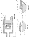
- FIGS. 1D-1F Another example of retaining mechanism 140 is shown in FIGS. 1D-1F .
- this example of retaining mechanism 140 is formed by guide protrusion 163 and housing protrusion 162.
- guide radial protrusion 163 contacts housing radial protrusion 162 thereby controlling further motion of inner guide 130 with respect to housing 120.
- this contact between guide radial protrusion 163 and housing radial protrusion 162 may also restrict (or block) flow channel 104.
- guide radial protrusion 163 and housing radial protrusion 162 may have a ring shape.
- This channel blocking may be used to isolate material 302 remaining in flow channel 104 from the environment (e.g., to slow the curing process of material 302 in flow channel 104).
- guide radial protrusions 163 may also move away from housing radial protrusion 162, which opens flow channel 104.
- the position of guide radial protrusions 163 may coincide with housing recess 164 while housing radial protrusions 162 may coincide with guide recess 165. This feature may be used to maintain a less restricted flow of material 302 through flow channel 104.
- Other examples of retaining mechanism 140 may include rods, straps, steps, and other like mechanism.
- applicator 100 also includes rotational mechanism 110 for rotating housing 120 with respect to part 152 and, in more specific embodiments, with respect to inner guide 130.
- the rotation may be performed when inner guide 130 sealingly engages fastener 156 as further described below with reference to FIGS. 2 and 3A-3E .
- inner guide 130 may be stationary with respect to fastener 156.
- Rotating mechanism 110 may include an electrical motor, hydraulic motor, pneumatic motor, robotic actuator, or other similar rotating mechanisms.
- rotational mechanism 110 may be used to rotate housing 120 during and/or following the delivery of material 302 into interface area 157. This rotation ensures that material 302 is free from voids, gaps, and/or inconsistencies and, for example, a more robust seal is formed by material 302 deposited in interface area 157.
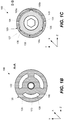
- FIG. 1B is a schematic cross-sectional representation of applicator 100 shown in FIG. 1A at a location identified as A-A along the length of applicator 100, in accordance with some embodiments.
- housing 120 includes center support 122, which may be used to threadably engage retaining mechanism 140 and/or supporting biasing mechanism 142.
- Center support 122 may connected to external wall 123 of housing 120 using one or more spokes 126.
- FIG. 1B shows spokes 126 extending through flow channel 104 and equally spaced.
- FIG. 1C is another schematic cross-sectional representation of applicator 100 shown in FIG. 1A at a location identified as B-B along the length of applicator 100, in accordance with some embodiments.
- housing 120 and inner guide 130 may form flow channel 104 for flowing material 302.
- material 302 flows from applicator 100 to housing contact surface 124 or, more specifically, into interface area 157.
- flow channel 104 has an annular shape. More specifically, flow channel 104 may extend around inner guide 130.
- one or more guiding protrusions 136 may extend through flow channel 104.
- inner guide 130 may include two or more guiding protrusions 136 extending into corresponding guiding recesses 127 of housing 120.
- FIG. 1C illustrates three guiding protrusions 136.
- Guiding protrusions 136 and guiding recesses 127 may define a sliding direction of inner guide 130 with respect to housing 120. In some embodiments, this sliding direction is linear (e.g., the X axis shown in FIG. 1C ).
- guiding protrusions 136 and guiding recesses 127 may be spiral such that housing 120 may rotate with respect to inner guide 130 (around the X axis) while housing 120 being advanced with respect to inner guide 130 (along the X axis). In other words, housing 120 both rotates (e.g., around its center axis) and linearly advances (e.g., along the same axis) respect to inner guide 130 at the same time. While FIG. 1C illustrates guiding protrusions 136 being parts of inner guide 130 and guiding recesses 127 being parts of housing 120, in some embodiments, guiding protrusions 136 are parts of housing 120 while guiding recesses 127 are parts of inner guide 130.
- FIG. 1C also illustrates an example in which guiding protrusions 136 restrict (or block) flow channel 104.
- flow channel 104 is not continuous and its portions 105a-105c are defined and separated by guiding protrusions 136 extend through flow channel 104.
- a portion of flow channel 104 extending over interface area 157 during operation of applicator 100 is unobstructed by any guiding protrusions 136 or spokes 126 and have a constant and continuous cross-sectional profile.
- flow channel 104 has a continuous ring structure. More specifically, two or more guiding protrusions 136 do not extend to housing contact surface 124 at least when inner guide 130 is in its retracted position 103.
- a part of flow channel 104 extending to housing contact surface 124 may be continuous at least when inner guide 130 is in retracted position 103.
- this part of flow channel 104 defines the shape of material 302 deposited in interface area 157.
- FIG. 1M is a schematic perspective representation of applicator 100 shown in FIG. 1A , in accordance with some embodiments.
- Inner guide 130 is shown protruding from housing 120 indicating that inner guide 130 is in its retracted position 103.
- inner guide contact surface 132 is also shown.
- the shape of inner guide contact surface 132 may corresponds to the shape of fastener 156 to, for example, ensure the sealing engagement and, in some embodiments, to ensure alignment of inner guide 130 or, more generally, applicator 100 with respect to fastener 156.
- retaining mechanism 140 for inner guide 130 Housing contact surface 124 is identified in this figure.
- the shape of housing contact surface 124 may correspond to the shape of part 152 to ensure the sealing engagement.
- FIG. 1M illustrates includes guide protrusion 136 depicted on inner guide 130. Guide protrusion 136 is discussed above with reference to FIGS. 1D-1F .
- FIG. 1G is a schematic cross-sectional representation of applicator 100 that has foam insert 170 positioned in flow channel 104 of applicator 100, in accordance with some embodiments.
- Foam insert 170 may be used to control delivery of material 302 through flow channel 104 and, in some embodiments, to further dispersed and/or intermix material 302 while material 302 passes through foam insert 170.
- foam insert 170 may be operable as a static mixer.
- Foam insert 170 may be made from an open cell foam material.
- foam insert 170 may be also used to support inner guide 130 with respect to housing 120.
- foam insert 170 may be operable as retaining mechanism 140 and/or as biasing mechanism 142.
- the flexibility of foam insert 170 may be used to move inner guide 130 with respect to housing 120 between retracted position 103 and protracted position 101 of inner guide 130.
- Foam insert 170 may have front insert surface 172. During operation of applicator 100, front insert surface 172 may extend into interface area 157 to fill interface area 157 with material 302. More specifically, front insert surface 172 may contact part surface 154 when material 302 is being delivered into interface area 157. In some embodiments, the inner surface of foam insert 170 may contact fastener surface 158 when material 302 is being delivered into interface area 157. This surface contact feature may help to ensure that material 302 is delivered to right part surface 154 and/or fastener surface 158. Furthermore, foam insert 170 may be compressed when contacting part surface 154 and/or fastener surface 158.
- front insert surface 172 may extend into interface area 157, material 302 may continue to be delivered while housing 120 is being disengaged from part 152.
- the distribution of material 302 is controlled by the shape of foam insert 170. In other words, material 302 may not be distributed beyond areas immediately surrounding foam insert 170.
- FIG. 1H is a schematic cross-sectional representation of applicator 100 having foam reservoir 174 operable as an inner guide.
- Foam reservoir 174 may function similar to foam insert 170 described above with reference to FIG. 1G .
- foam reservoir 174 may be used to control delivery of material 302 and, in some embodiments, to further dispersed and/or intermix material 302.
- Foam reservoir 174 may be made from an open cell foam material.
- foam reservoir 174 expands when filled with delivered material 302. Unlike an applicator with foam insert 170, applicator 100 having foam reservoir 174 does not have a separate inner guide.
- Foam reservoir 174 may include reservoir front surface 178. Foam reservoir 174 delivers material 302 into interface area 157 when, for example, reservoir front surface 178 extends into interface area 157 or, more specifically, contacts fastener surface 158 and/or part surface 154 within interface area 157. Foam reservoir 174 may be supported by external wall 123 of housing 120 and/or center support 122 of housing 120.
- applicator 100 is a disposable applicator. Specifically, applicator 100 may be disposed when material 302 delivered by applicator 100 starts curing inside applicator 100, for example, after applicator 100 is not used for a prolonged period of time, which depends on the curing characteristics of material 302. In some embodiments, curing of material 302 inside applicator 100 may be slowed down or even completely stopped by isolating material 302 remaining in applicator 100 from the environment.
- One example of features used to seal channel 104 is described above with reference to FIGS. 1D-1F . Additional examples of such features are presented in FIGS. 1I-1L . Another reason to dispose applicator 100 is, for example, when applicator 100 becomes clogged even before material 302 cures.
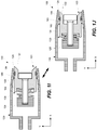
- FIGS. 1I and 1J are schematic cross-sectional representations of applicator 100 including a channel sealing mechanism formed by first seal 182, second seal 184, and bypass 180.
- first seal 182 and second seal 184 are attached to or at least movable together with inner guide 130.
- bypass 180 is provided in with inner guide 130.
- Bypass 180 interconnects a portion of flow channel 104 positioned between first seal 182 and second seal 184 a portion of flow channel 104 positioned between second seal 184 and inner guide contact surface 132.
- first seal 182, second seal 184, and bypass 180 may be parts of housing 120.
- FIG. 1I illustrates applicator 100 with inner guide 130 shown in its protracted position 101.
- first seal 182 restricts (and, in some cases, blocks) flow channel 104 such that material 302 cannot flow from cavity 128 to housing contact surface 124.
- no material 302 can be delivered when inner guide 130 is in its protracted position 101.
- any material 302 within cavity 128 is isolated from the environment by first seal 182. Any material 302 remaining between first seal 182 and housing contact surface 124 may be flushed out prior to subsequent use of applicator 100.
- FIG. 1J illustrates applicator 100 with inner guide 130 shown in its retracted position 103.
- second seal 184 also restricts (and, in some cases, blocks) flow channel 104.
- Material 302 can flow from cavity 128 to housing contact surface 124 through bypass 180.
- bypass 180 may be viewed as a part of flow channel 104 in this position of inner guide 130.
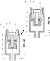
- FIGS. 1K and 1L are schematic cross-sectional representations of applicator 100 with channel 104 being sealed using main seal 192 connected to or at least movable together with inner guide 130.
- flow channel 104 has a different profile along center axis 112. Specifically, flow channel 104 is narrower closer to housing contact surface 124 and opens up into cavity 128. Because of this profile difference, flow channel 104 is either restricted (and, in some cases, blocked) by main seal 192 or not depending on the position of inner guide 130.
- FIG. 1K illustrates applicator 100 with inner guide 130 in its protracted position 101 and flow channel 104 being restricted (and, in some cases, blocked) by main seal 192.
- FIG. 1L illustrates applicator 100 with inner guide 130 in its retracted position 103 and flow channel 104 not restricted (or blocked) by main seal 192.
- main seal 192 is moved where flow channel 104 is wider and material 302 can flow through flow channel 104 around main seal 192.
- FIG. 2 is a process flowchart corresponding to method 200 for applying material 302 at interface area 157, in accordance with some embodiments.
- Method 200 may use applicator 100, various examples of which are described above. In some embodiments, method 200 may be practiced with other types of applicators or equipment.
- Interface area 157 is defined as an area surrounding the interface between part 152 and fastener 156, for example.
- the deposit of material 302 formed in interface area 157 during method 200 may be in the form of a fillet or have any other shape providing sealing to the interface.
- method 200 may be used to apply material 302 at any other control area that may not necessarily be defined as an interface area. In general, method 200 may be used for applying material 302 at a control area such that other areas surrounding the control area may not be contamimated with applied material 302.
- Method 200 may proceed with sealing interface 157 area during operation 201.
- Interface area 157 is sealed from a remaining surface of fastener 156 and a remaining surface of part 152, according to some embodiments. These remaining surfaces do not extend into interface area 157.
- operation 201 involves sealingly engaging fastener 156 during operation 202 followed by sealing engaging part 152 during operation 204.
- fastener 156 may be sealingly engaged by inner guide 130 during operation 202.
- Inner guide contact surface 132 may be pressed against fastener surface 158.
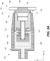
- FIG. 3A is a schematic cross-sectional representation of applicator 100 and fastener assembly 150 after operation 202.
- fastener 156 is in contact with inner guide 130 or, more specifically, inner guide contact surface 132 is pressed against fastener surface 158.
- inner guide contact surface 132 is pressed against fastener surface 158
- applicator 100 is self-aligned with respect to fastener 156. This self-alignment may be achieved by using a particular shape for inner guide contact surface 132 that, for example, mates with fastener surface 158 forcing inner guide 130 and, more generally, applicator 100 into a particular orientation.
- FIG. 3A illustrates inner guide 130 in its protracted position 101 with a portion 113 of inner guide 130 extending outside of housing 120.
- Inner guide 130 moves into its retracted position 103 in a later operation further described below.
- Interface area 157 is not completely sealed at this stage.
- material 302 is not delivered into interface area 157 at this stage.
- Inner guide contact surface 132 may have a profile of fastener surface 158 for sealing.
- inner guide contact surface 132 may have a coned shape to match fastener surface 158, which may be (at least in part a chamfer on the head of fastener 156).
- inner guide contact surface 132 may a shape to accommodate any other shape of fastener, such as splined nuts/heads, hex nuts/heads, and the like.
- part 152 may be sealingly engaged during operation 204.
- inner guide 130 of applicator 100 may be slid with respect to and inside housing 120 until housing 120 contacts part 152 or, more specifically, until housing contact surface 124 sealingly engages part surface 154.
- interface area 157 may be sealed and ready to receive material 302. Because interface area 157 is sealed, material 302 does not go outside of interface area 157.
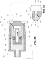
- FIG. 3B is a schematic cross-sectional representation of applicator 100 and fastener assembly 150 after operation 204.
- Inner guide 130 is now in its retracted position 103.
- inner guide 130 may be disposed within cavity 128 of housing 120 such that inner guide 130 does not extend outside of cavity 128.
- FIG. 3C is a schematic expanded view of portion (also identified in FIG. 3B with a dashed boundary) around interface area 157.
- interface area 157 has void.
- interface area 157 may not include any material 302 at this state.
- some material 302 may be carried into interface area 157 during operation 204, for example by advancing housing 120 toward part 152.
- method 200 may proceed with form deposit 314 of material 302 in interface area 157 area during operation 205.
- Deposit 314 is formed simultaneously around the entire perimeter of interface area 157. Specifically, material 302 may flow through the flow channel of the applicator onto the interface area.
- material 302 is substantially contained within interface area 157. In other words, material 302 does not go onto other portions of fastener 156 and part 152 that are not within interface area 157.
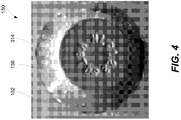
- Deposit 314 may have a continuous ring shape as, for example, shown in FIG. 4 and further described below.
- deposit 214 is formed simultaneously around the entire perimeter of interface area 157.
- material 302 is delivered to interface area 157 by flowing material 302 through a flow channel an applicator as describe above with reference to FIGS. 1A-1M .
- the flow channel has a ring shape and is defined by the internal wall of the housing of the applicator as well as by the external wall of the inner guide of the applicator.
- method 200 may involve rotating at least a portion of applicator 100 with respect to fastener 156 and part 152.
- housing 120 of applicator 100 may be rotated with respect to fastener 156 and part 152, while inner guide 130 may remain stationary.
- housing 120 may remain stationary, while inner guide 130 may be rotated with respect to fastener 156 and part 152.
- inner guide 130 and housing 120 may be both rotated (e.g., with the same rotational speed) with respect to fastener 156 and part 152.
- the rotation may be used to eliminate any voids or inconsistencies in material 302 provided into interface area 157 by redistributing material 302 within interface area 157. For example, eliminate any voids or inconsistencies in material 302 may be due to the surface tension, viscosity of material 302 and other factors. It should be noted that the rotation is optional and, in some embodiments, the rotation is not performed. Furthermore, it should be noted that when the rotation is performed, it is performed while interface area 157 remains sealed. As such, this rotation is different from a swirling motion used in a conventional process described above. Furthermore, the rotation can be to fare the fillet or, more generally, deposit 314 formed by material 302.
- FIG. 3D is a schematic cross-sectional representation of applicator 100 and fastener assembly 150 after operation 206, in accordance with some embodiments, while FIG. 3E is a schematic expanded view of portion (identified in FIG. 3D with a dashed boundary).
- interface area 157 is filled with material 302. Material 302 is contained within interface area 157 since housing 120 remains sealingly engaged to part 152 and inner guide remains sealingly engaged to fastener 156.
- operation 207 may involve disengaging part 152 from housing 120 during operation 208 and then disengaging fastener 156 from inner guide 130 during operation 210.
- inner guide 130 may slide with respect to housing 120 from retracted position 103 to protracted position 101 of inner guide 130.
- FIG. 3F is a schematic cross-sectional representation of applicator 100 and fastener assembly 150 after operation 208
- FIG. 3G is a schematic expanded view of portion (identified in FIG. 3F with a dashed line boundary). It should be noted that while part 152 is being disengaged from housing 120 during operation 208, fastener 156 remains engaged to inner guide 130 during this operation.
- operation 210 may be performed after completing operation 208.
- fastener 156 is disengaged from inner guide 130 or, more specifically, from inner guide contact surface 132.
- interface area 157 is fully exposed and filled with material 302.
- housing 120 and inner guide 130 do not contact part 152, fastener 156, or material 302 disposed within interface area 157.
- Material 302 may be contained within interface area 157 due to its viscosity.
- material 302 is at least partially cured at the end of operation 210, which also completes operation 207.
- FIG. 3H is a schematic cross-sectional representation of fastener assembly 150 after operation 207 is completed. The applicator is away from fastener assembly 150 and, therefore, is not shown in FIG. 3H.
- FIG. 3I is a schematic expanded view a portion identified with a dashed line boundary in FIG. 3H .
- Deposit 314 is positioned in interface area 157 and may have the shape of a fillet or any other suitable shape. In some embodiments, the shape of deposit 314 is substantially the same as the shape of interface area 157, which was sealed during earlier operation. While interface area 157 is filled with material 302 thereby forming deposit 314, the remaining surfaces of fastener 156 and part 152 (outside of the interface area) may be free from material 302.
- the material When the same material is applied using a conventional technique, the material completely covers the fastener.
- the tip of the material deposit in such a way may have an uneven surface, which in some embodiments may result in voids.
- the amount of material deposited using the conventional technique is at least double the amount of material deposited using techniques described herein.
- the sealing characteristics of the material deposited using methods and systems described herein are improved because the material is distributed in a more controlled location (e.g., into an interface area, where it is used for sealing).
- the deposited material is redistributed after it being dispensed into the interface area to eliminate voids.
- illustrative method 1100 may include specification and design (operation 1104) of aircraft 1102 and material procurement (operation 1106).
- operation 1106 component and subassembly manufacturing
- operation 1110 system integration
- aircraft 1102 may go through certification and delivery 1112 to be placed in service (operation 1114).
- operation 1116 routine maintenance and service
- Various materials may be applied using techniques described herein during one or more of operations 1108, 1110, 1114, and 1116.
- illustrative method 1100 may be performed or carried out by a system integrator, a third party, and/or an operator (e.g., a customer).
- a system integrator may include any number of aircraft manufacturers and major-system subcontractors.
- a third party may include any number of vendors, subcontractors, and suppliers.
- an operator may be an airline, leasing company, military entity, service organization, and so on.
- aircraft 1102 may include airframe 1118 with a plurality of high-level systems 1120 and interior 1122.
- high-level systems 1120 include one or more of propulsion system 1124, electrical system 1126, hydraulic system 1128, and environmental system 1130. Any number of other systems may be included.
- This example related to aerospace applications.
- the principles disclosed herein may be applied to other industries, such as the automotive industry. Accordingly, in addition to aircraft 1102, the principles disclosed herein may apply to other vehicles, e.g., land vehicles, marine vehicles, space vehicles, etc.
- the sealing techniques described herein may be used for sealing penetrations through the skin of the wing or fuselage or fasteners through an exterior surface or for sealing fasteners in the environment potentially exposed to moisture on the interior.
- Apparatus and methods shown or described herein may be employed during any one or more of the stages of the aircraft manufacturing and service method 1100.
- components or subassemblies corresponding to component and subassembly manufacturing 1108 may be fabricated or manufactured in a manner similar to components or subassemblies produced while aircraft 1102 is in service.
- one or more aspects of the apparatus, method, or combination thereof may be utilized during operations 1108 and 1110, for example, by substantially expediting assembly of or reducing the cost of aircraft 1102.
- one or more aspects of the apparatus or method realizations, or a combination thereof may be utilized, for example, while aircraft 1102 is in service, e.g., maintenance and service 1116.
Landscapes
- Engineering & Computer Science (AREA)
- Mechanical Engineering (AREA)
- General Engineering & Computer Science (AREA)
- Manufacturing & Machinery (AREA)
- Transportation (AREA)
- Aviation & Aerospace Engineering (AREA)
- Coating Apparatus (AREA)
- Gasket Seals (AREA)
- Application Of Or Painting With Fluid Materials (AREA)
Abstract
Description
- This disclosure generally relates to systems and methods for applying materials on interface areas or, more specifically, to systems and methods using applicators for sealing the interface areas and delivering materials to the interface areas such that component portions outside of these interface areas remain substantially free from the materials.
- Many interfaces on aircraft structures and other types of structure may be sealed from various environmental elements, such as water, to keep these elements from penetrating through these interfaces and, in some cases, to ensure containment of the internal environment. One example of such interface is an interface between a fastener (e.g., a rivet) and aircraft skin. One area of concern is sealing fasteners inside wings, particularly wings that serve as fuel tanks. Even small gaps may be of concern because a typical commercial aircraft may have thousands of rivets and other fasteners that are sealed. To cover gaps in these interfaces, various sealants may be used during or after installation of the fasteners. For example, a sealant may be deposited onto an internal surface of a skin at an interface area between formed by the skin and fastener. This application is typically performed using a handheld tool and involves manually aligning a dispensing nozzle with the fastener.
- Furthermore, to cover and fill the interface area with the material, a circular motion may be performed guiding the tip of the dispensing nozzle around the perimeter of the interface. For example, a portion of the fastener interfacing with a planar part may have a round shape defining a ring-shaped interface area. Maintaining the alignment is difficult during this circular motion and some material gets into the areas away from the interface.
- Furthermore, a similar circular motion may be performed to break the flow of the material. Specifically, a circular motion may be performed while retracting the application tool and separating the application tool from the applied material or, more specifically, in order to separate/break the application string of sealant from the dispensing nozzle. This circular motion is similar to the motion used to finish off application of soft ice cream into an ice cream cone. This application generally results in the fastener being fully covered with the sealant and not just the interface area. There are a few concerning issues with this approach.
- The manual alignment and circular motions performed during application of a sealant take a significant amount of time. This time can be very extensive when viewed in light of the many thousands of fasteners that are being sealed on the same aircraft. This time results in added cost. Furthermore, the use of a handheld tool results more sealant than necessary being deposited to cover the interfaces. This excess is costly from the material consumption perspective. It also adds excessive weight to the resulting assembly often as much as 20-50 pounds for the same aircraft for the sealed fasteners. In some cases, the handheld tool and even robotic tools may be difficult to align with the rest to the sealing area and some gaps may remain exposed even when excessive amounts of sealant are deposited. Finally, fasteners that are not properly sealed may be reworked, which adds considerable time and cost to the manufacturing process.
- Provided are methods and systems for applying materials to interface areas formed by fasteners and parts. Specifically, a material is applied to an interface area while portions of the fastener and part outside of this interface area remain substantially free from the material. For purposes of this disclosure, an interface area is defined as an area including and surrounding the interface (e.g., a seam) between the part and fastener and covering gaps in this interface. The interface area also includes surrounding portions of the part and fastener forming this interface. The size and share of the interface area may depend on the geometry of the part and fastener, on the size and shape of the interface, and/or on the amount and properties of the material used at this interface to achieve various functions, such as sealing, bonding, and the like. When the material is applied into the interface area, the interface area may be sealed off from the remaining portions of the part and fastener by the applicator or, more specifically, by applicator's housing and inner guide. As such, a controlled amount of the material is dispensed in a precise location defined by the interface area. The material may be delivered through an annular flow channel between the housing external wall and inner guide. The inner guide may be sealingly engaged with the fastener and, in some embodiments, the inner guide may be centered with respect to the fastener. The housing may be sealingly engaged with respect to the part and, in some embodiments, may be rotated with respect to the part to redistribute the material at the interface area.
- In some embodiments, an applicator is configured to form a deposit of a material in an interface area. The interface area may be formed by a fastener and a part and may have a ring shape. The deposit is contained within the interface area while maintaining a portion of the fastener free (outside of the interface area) from the material.
- In some embodiments, the applicator includes a housing and inner guide. The housing defines a cavity. The inner guide is slidably disposed within the cavity of the housing. The housing and inner guide may form a flow channel within the cavity. More specifically, the flow channel is formed between the internal wall of the inner guide and the external wall of the housing. The flow channel may have a rind shape. More specifically, the shape of the flow channel at the exit may match the shape of the interface area.
- In some embodiments, the housing has a housing contact surface for sealingly engaging the part partially defining the interface area. The inner guide may have an inner guide contact surface for sealingly engaging the fastener partially defining the interface area. The inner guide may be configured to slide with respect to the housing between a retracted position and protracted position. A portion of the inner guide may extend outside of the housing beyond the housing contact surface when the inner guide is in its protracted position. In its retracted position, the inner guide may be positioned within the cavity of the housing when the inner guide is in the retracted position.
- In some embodiments, the inner guide includes two or more guiding protrusions extending into corresponding guiding recesses of the housing. Alternatively, the housing includes two or more guiding protrusions extending into corresponding guiding recesses of the inner guide. The two or more guiding protrusions and the corresponding guiding recesses define a sliding direction of the inner guide with respect to the housing. In some embodiments, the two or more guiding protrusions do not extend to the housing contact surface, at least when the inner guide is in its retracted position. Specifically, a part of the flow channel extending to the housing contact surface may be continuous, at least when the inner guide is in its retracted position. In other words, the ring shape of a part of the flow channel extending to the housing contact surface is continuous. This part of the flow channel may define the shape of the material formed at the interface area between the part and fastener.
- In some embodiments, the flow channel is restricted when the inner guide is in its protracted position. Various features, such as channel sealing mechanisms, may be provided on the inner guide and/or the housing to restrict the flow channel as further described below. In some embodiments, a channel sealing mechanism may be also operable as a retaining mechanism that keeps the inner guide from sliding put of the housing beyond its protracted position.
- In some embodiments, the inner guide is porous. Specifically, the inner guide may be configured to pass the material through the inner guide. For example, the inner guide may be formed from open-cell foam.
- In some embodiments, the applicator also includes a biasing mechanism disposed between the housing and the inner guide. The biasing mechanism may urge the inner guide from the retracted position into the protracted position. One example of the biasing mechanism is a spring.
- In some embodiments, the applicator also includes a retaining mechanism keeping the inner guide from protracting outside of the housing beyond the protracted position. For example, the retaining mechanism may be a bolt protruding through the inner guide and being threadably attached to the housing. The inner guide may be slidably disposed on the bolt and configured to slide on the bolt between the retracted position and protracted position. In another example, a retaining mechanism may block the flow channel when the inner guide in in the protracted position.
- In some embodiments, the applicator also includes a rotational mechanism for rotating the housing with respect to the part and, in some embodiments, with respect to the inner guide. The rotation may be performed when the inner guide sealingly engages the fastener. During this rotation, the inner guide may be stationary with respect to the fastener.
- Provided also is a method for depositing a material in an interface area, according to some embodiments. The method may involve forming a deposit of the material having a continuous ring shape. The deposit is formed simultaneously around the entire perimeter of the interface area. The deposit is formed by flowing the material through a flow channel of an applicator onto the interface area. The interface area is defined by a fastener and a part.
- In some embodiments, prior to forming the deposit, the method also involves sealing the interface area formed by a fastener and part from a remaining surface of the fastener and a remaining surface of the part. The remaining surface of the fastener is positioned outside of the interface area, and the remaining surface of the part is also positioned outside of the interface area.
- In some embodiments, sealing the interface area involves sealingly engaging the fastener with, for example, the inner guide of an applicator or, more specifically, with the inner guide sealing surface. The inner guide may be in its protracted position. In some embodiments, a portion of the inner guide may extend outside of a housing of the applicator. Sealingly engaging the fastener may also align the applicator with respect to the fastener.
- In some embodiments, sealing the interface area may also involve sealingly engaging the part with, for example, the housing of the applicator or, more specifically, with the housing sealing surface. During this operation, the inner guide slides with respect to the housing from its protracted position to its retracted position.
- After forming the deposit, the method may continue with exposing the interface area having the deposit. In some embodiments, exposing the interface area may involve disengaging the part from the applicator and subsequently disengaging the fastener from the applicator. After exposing the interface area, the remaining surface of the fastener and the remaining surface of the part beyond interface area may be substantially free from the material. The remaining surface of the fastener and the remaining surface of the part are positioned outside of the interface area.
- Having thus described examples of the disclosure in general terms, reference will now be made to the accompanying drawings, which are not necessarily drawn to scale, and wherein like reference characters designate the same or similar parts throughout the several views, and wherein:
-
FIG. 1A is a schematic cross-sectional representation of an applicator illustrating various internal components of the applicator, in accordance with some embodiments. -
FIGS. 1B and 1C are two schematic cross-sectional representations of the applicator shown inFIG. 1A at different locations along the length of the applicator, in accordance with some embodiments. -
FIG. 1D is a schematic cross-sectional representation of the applicator including a different retaining mechanism operable to restrict a flow channel of the applicator, in accordance with some embodiments. -
FIGS. 1E and 1F are schematic expanded views of a portion of the applicator ofFIG. 1D further illustrating various features of the retaining mechanism with the inner guide shown in its retracted and the protracted position, in accordance with some embodiments. -
FIG. 1G is a schematic cross-sectional representation of the applicator including the inner guide and a foam insert positioned in the flow channel of the applicator, in accordance with some embodiments. -
FIG. 1H is a schematic cross-sectional representation of the applicator with the inner guide made from a foam material, in accordance with some embodiments. -
FIGS. 1I and 1J are schematic cross-sectional representations of the applicator including a channel sealing mechanism with the inner guide shown in the protracted position and the retracted position, respectively, in accordance with some embodiments. -
FIGS. 1K and 1L are schematic cross-sectional representations of the applicator including a different channel sealing mechanism with the inner guide shown in its protracted position and the retracted position, respectively, in accordance with some embodiments. -
FIG. 1M is a schematic perspective representation of the applicator including guide protrusion, in accordance with some embodiments. -
FIG. 2 is a process flowchart corresponding to a method for applying a material to an interface area, in accordance with some embodiments. -
FIG. 3A is a schematic cross-sectional representation of the applicator and the fastener assembly after sealingly engaging the fastener with the inner guide contact surface of the inner guide of the applicator, in accordance with some embodiments. -
FIG. 3B is a schematic cross-sectional representation of the applicator and the fastener assembly after sealingly engaging the part with the housing contact surface of the housing, in accordance with some embodiments. -
FIG. 3C is a schematic expanded view of a portion identified inFIG. 3B and illustrating the interface area sealed and isolated from the remaining portions the fastener and the part of the fastener assembly shown inFIG. 3B , in accordance with some embodiments. -
FIG. 3D is a schematic cross-sectional representation of the applicator and the fastener assembly after delivering the material to the interface area, in accordance with some embodiments. -
FIG. 3E is a schematic expanded view of a portion identified inFIG. 3D showing the interface area filled with the materials, in accordance with some embodiments. -
FIG. 3F is a schematic cross-sectional representation of the applicator and the fastener assembly after disengaging the part from the housing contact surface of the housing, in accordance with some embodiments. -
FIG. 3G is a schematic expanded view of a portion identified inFIG. 3F , in accordance with some embodiments. -
FIG. 3H is a schematic cross-sectional representation of the fastener assembly after the applicator is disengaged from the fastener assembly and the interface area is filled with the materials and is exposed, in accordance with some embodiments. -
FIG. 3I is a schematic expanded view of a portion identified inFIG. 3H , in accordance with some embodiments. -
FIG. 4 is a photograph of a test fastener assembly having a material applied to the interface area of the assembly, in accordance with material application techniques described herein. -
FIG. 5 is a diagram of an aircraft production and service methodology that may utilize one or more material application systems and methods described herein. -
FIG. 6 is a schematic illustration of an aircraft that may utilize parts and fasteners with their interfaces sealed using material application systems and methods described herein. - In the following description, numerous specific details are set forth in order to provide a thorough understanding of the presented concepts. The presented concepts may be practiced without some of these specific details. In other instances, well known process operations have not been described in detail so as to not unnecessarily obscure the described concepts. While some concepts will be described in conjunction with the specific examples, it will be understood that these examples are not intended to be limiting.
- As noted above, applying viscous liquids, slurries, and other similar types of materials to specific areas in a relatively fast and precise manner is a challenging task. These applied materials may be used for sealing interfaces or other purposes (e.g., bonding) such that the materials sufficiently cover these interfaces and have no voids or gaps. Provided are methods and systems for applying materials to interface areas between fasteners and parts. Specifically, a material is applied to an interface area such that at least a portion of the fastener remains free from the material. This portion of the fastener extends outside of the interface area. The interface area may be sealed such that the material is not spread beyond the designated and contained space. As such, a controlled amount of the material is dispensed in a precise location. An applicator used for this process may include a housing and inner guide slidably disposed within this housing. The material may be delivered through an annular flow channel between the housing wall and the inner guide. The inner guide may be sealingly engaged with and, in some embodiments, centered with respect to the fastener. The housing may be sealingly engaged with respect to the part and, in some embodiments, may be rotated with respect to the part to redistribute the material at the interface area.
- This applicator may be used to apply various materials, such as sealants, adhesives, and other like materials. Even with smaller amounts of applied material, it may fill gaps within the interface area. At the same time, excessive material is not deposited in other areas away from the interface. Furthermore, the material may be redistributed within the interface area to ensure the material deposit being void-free and gap-free. In some embodiments, the material applied to the interface area may have a shape of a circular fillet around the base of the fastener head. While references may be made to sealing an interface between the fastener head and part, one having ordinary skills in the art that this disclosure is not limited to any particular examples unless specifically claimed. For example, a sealing interface may be between a nut of the fastener and part such that the nut is disposed inside the aircraft (e.g., the part may be an aircraft skin). Other applications and sealing interfaces are also within the scope.
- The proposed methods and systems help to reduce amounts of deposited materials resulting in weight reduction and costs savings. Furthermore, these methods and systems substantially reduce the processing time in comparison, for example, to manual application techniques currently used in many industries. For example, the proposed method and systems render unnecessary a breakoff operation or a circular motion often used in a conventional operation technique. Finally, these methods and systems ensure void-free and gap-free sealing of the interface.
-
FIG. 1A is a schematic cross-sectional representation ofapplicator 100 illustrating details and arrangement of various internal components ofapplicator 100, in accordance with some embodiments.Fastener assembly 150 includingfastener 156 andpart 152 is shown in this figure for reference and is not a part ofapplicator 100.Applicator 100 is configured to apply a material at interface area 157 (shown with dotted lines inFIG. 1A ) betweenfastener 156 andpart 152 while maintaining a portion offastener 156 outside ofinterface area 157 free from the applied material. Furthermore, a portion ofpart 152 outside ofinterface area 157 is also maintained free from the applied material.Interface area 157 may have a shape of a fillet or have other suitable shapes providing sealing and other characteristics. -
Material 302 disposed withinapplicator 100 and later dispensed intointerface area 157 is shown inFIGS. 3A-I further described below. In some embodiments,material 302 applied tointerface area 157 may be a sealant.Fastener 156 may be a rivet, bolt, HI-LOCK™ (including a threaded pin and a threaded collar, which may an elliptical internal thread shape). In n some embodiments, fastener assembly is a bolt and nut-collar combinations where the lower seam between the bottom of the nut-collar and structure, as well as the top seam between the nut-collar and bolt is sealed. In some embodiments,part 152 may be an aircraft skin. One having ordinary skills in the art would understand thatapplicator 100 may be used to apply various materials to various types of controlled areas. -
Applicator 100 includeshousing 120 andinner guide 130.Housing 120 definescavity 128, which provides space forinner guide 130.Housing 120 hashousing contact surface 124 for sealinglyengaging part 152 as further described below with reference toFIGS. 2 and3B-3C .Housing contact surface 124 is positioned ontip 125 ofhousing 120. -
Housing 120 andinner guide 130form flow channel 140 withincavity 128. Specifically,flow channel 140 is formed betweeninternal wall 129 ofhousing 120 andexternal wall 131 ofinner guide 130 as, for example, shown inFIGS. 1B and 1C .Flow channel 140 may have a ring shape as further described below with reference toFIGS. 1C and other figures. -
FIG. 1A also illustratescenter axis 112 ofhousing 120 or, more generally, ofapplicator 100. In some embodiments,applicator 100 self-centers with respect tofastener 156 such thatcenter axis 112 may coincide withcenter axis 159 offastener 156. This self-centering may be achieved when, for example,inner guide 130 sealingly engagesfastener 156 or, more specifically, when innerguide contact surface 132contacts fastener surface 158, as further described below. -
Inner guide 130 may be slidably disposed withincavity 128 ofhousing 120.Inner guide 130 includes innerguide contact surface 132 for sealingly engagingfastener 154 as further described below with reference toFIGS. 2 and3A .Inner guide 130 may be configured to slide with respect tohousing 120 between its retractedposition 103 andprotracted position 101. For example,inner guide 130 may slide within and with respect tohousing 120 alongcenter axis 112.FIG. 1A illustratesinner guide 130 in itsprotracted position 101. In some embodiments, a portion ofinner guide 130 may extend outside ofhousing 120 beyondhousing contact surface 124 in thisprotracted position 101. This extension may help to initially aligninner guide 130 withrespect fastener 156 during operation. It should be noted that additional self-alignment betweeninner guide 130 andrespect fastener 156 may occur wheninner guide 130 contacts respectfastener 156. Alternatively,inner guide 130 may be positioned withincavity 128 ofhousing 120 even wheninner guide 130 is in itsprotracted position 101. -
FIGS. 3D and 3E illustrateinner guide 130 in its retractedposition 103. Generally,inner guide 130 does not extend outside ofhousing 120 wheninner guide 130 is in its retractedposition 103. Asinner guide 130 moves from itsprotracted position 101 into its retractedposition 103,inner guide 130 moves deeper intocavity 128 ofhousing 120. In these rear situations,inner guide 130 may extend outside ofhousing 120 even wheninner guide 130 is in its retractedposition 103. In some embodiments,inner guide 130 and/ orhousing 120 is made from a plastic. For example,inner guide 130 and/ orhousing 120 is rotated with respect topart 152 andfastener 156, the softer material ofinner guide 130 and/ orhousing 120 protectspart 152 andfastener 156, which may be made from harder materials. For example,part 152 andfastener 156 may be made from metal, whileinner guide 130 andhousing 120 may be made from plastic. Furthermore,applicator 100 may be disposable. - In some embodiments,
applicator 100 also includesbiasing mechanism 142 disposed betweenhousing 120 andinner guide 130 or, more specifically, betweencenter support 122 ofhousing 120 andinner guide 130.Biasing mechanism 142 may urgeinner guide 130 from its retractedposition 103 into itsprotracted position 101. One example of biasingmechanism 142 is a spring, such as a coil spring, pneumatic cylinder, foam structure, rubber structure, or alike. During operation,biasing mechanism 142 also helps to sealingly engageinner guide 130 againstfastener 156 or, more specifically, to sealingly engage innerguide contact surface 132 againstfastener surface 158.Force 143 with whichbiasing mechanism 142 urgesinner guide 130 out of retracted position as shown inFIG. 3B (and into its protracted position 101) may be selected to provide sufficient sealing (e.g., based on the pressure, viscosity, and surface tension ofmaterial 302 being delivered intointerface area 157 as well geometry of interface area). Furthermore, this force may be selected based on ability to advanceinner guide 130 into its retractedposition 103 and to sealingly engagehousing 120 withpart 152.Retaining mechanism 140, such as a bolt as, e.g., shown inFIG. 1A , may extend throughbiasing mechanism 142, when retainingmechanism 140 is used inapplicator 100. - In some embodiments,
applicator 100 also includes aretaining mechanism 140 that keepsinner guide 130 from extending outside ofhousing 120 beyond theprotracted position 101 ofinner guide 130. For example, retainingmechanism 140 may be a bolt protruding throughinner guide 130 and threadably attached tocenter support 122 ofhousing 120 as, for example, shown inFIG. 1A .Inner guide 130 may be slidably disposed on retainingmechanism 140 and configured to slide with respect to retainingmechanism 140 between retractedposition 103 andprotracted position 101. - Another example of retaining
mechanism 140 is shown inFIGS. 1D-1F . Specifically, this example of retainingmechanism 140 is formed byguide protrusion 163 andhousing protrusion 162. Wheninner guide 130 is in itsprotracted position 101 as shown inFIG. 1E , guideradial protrusion 163 contacts housingradial protrusion 162 thereby controlling further motion ofinner guide 130 with respect tohousing 120. It should be noted that this contact between guideradial protrusion 163 and housingradial protrusion 162 may also restrict (or block)flow channel 104. For example, guideradial protrusion 163 and housingradial protrusion 162 may have a ring shape. This channel blocking may be used to isolatematerial 302 remaining inflow channel 104 from the environment (e.g., to slow the curing process ofmaterial 302 in flow channel 104). Asinner guide 130 advances into its retractedposition 103 as shown inFIG. 1F , guideradial protrusions 163 may also move away from housingradial protrusion 162, which opensflow channel 104. In some embodiments, wheninner guide 130 is in its retractedposition 103, the position of guideradial protrusions 163 may coincide withhousing recess 164 while housingradial protrusions 162 may coincide withguide recess 165. This feature may be used to maintain a less restricted flow ofmaterial 302 throughflow channel 104. Other examples of retainingmechanism 140 may include rods, straps, steps, and other like mechanism. - In some embodiments,
applicator 100 also includesrotational mechanism 110 for rotatinghousing 120 with respect topart 152 and, in more specific embodiments, with respect toinner guide 130. The rotation may be performed wheninner guide 130 sealingly engagesfastener 156 as further described below with reference toFIGS. 2 and3A-3E . During this rotation,inner guide 130 may be stationary with respect tofastener 156.Rotating mechanism 110 may include an electrical motor, hydraulic motor, pneumatic motor, robotic actuator, or other similar rotating mechanisms. In some embodiments,rotational mechanism 110 may be used to rotatehousing 120 during and/or following the delivery ofmaterial 302 intointerface area 157. This rotation ensures thatmaterial 302 is free from voids, gaps, and/or inconsistencies and, for example, a more robust seal is formed bymaterial 302 deposited ininterface area 157. -
FIG. 1B is a schematic cross-sectional representation ofapplicator 100 shown inFIG. 1A at a location identified as A-A along the length ofapplicator 100, in accordance with some embodiments. As shown inFIG. 1B ,housing 120 includescenter support 122, which may be used to threadably engage retainingmechanism 140 and/or supportingbiasing mechanism 142.Center support 122 may connected toexternal wall 123 ofhousing 120 using one or more spokes 126.FIG. 1B showsspokes 126 extending throughflow channel 104 and equally spaced. -
FIG. 1C is another schematic cross-sectional representation ofapplicator 100 shown inFIG. 1A at a location identified as B-B along the length ofapplicator 100, in accordance with some embodiments. As shown inFIG. 1C ,housing 120 andinner guide 130 may formflow channel 104 for flowingmaterial 302. Specifically, during operation ofapplicator 100,material 302 flows fromapplicator 100 tohousing contact surface 124 or, more specifically, intointerface area 157. In some embodiments,flow channel 104 has an annular shape. More specifically,flow channel 104 may extend aroundinner guide 130. In some embodiments, one or more guidingprotrusions 136 may extend throughflow channel 104. - Specifically,
inner guide 130 may include two or more guidingprotrusions 136 extending into corresponding guidingrecesses 127 ofhousing 120.FIG. 1C illustrates three guidingprotrusions 136. One having ordinary skills in the art would understand that any number of guidingprotrusions 136 may be used. Guidingprotrusions 136 and guidingrecesses 127 may define a sliding direction ofinner guide 130 with respect tohousing 120. In some embodiments, this sliding direction is linear (e.g., the X axis shown inFIG. 1C ). Alternatively, guidingprotrusions 136 and guidingrecesses 127 may be spiral such thathousing 120 may rotate with respect to inner guide 130 (around the X axis) whilehousing 120 being advanced with respect to inner guide 130 (along the X axis). In other words,housing 120 both rotates (e.g., around its center axis) and linearly advances (e.g., along the same axis) respect toinner guide 130 at the same time. WhileFIG. 1C illustrates guidingprotrusions 136 being parts ofinner guide 130 and guidingrecesses 127 being parts ofhousing 120, in some embodiments, guidingprotrusions 136 are parts ofhousing 120 while guidingrecesses 127 are parts ofinner guide 130. -
FIG. 1C also illustrates an example in which guidingprotrusions 136 restrict (or block)flow channel 104. As such,flow channel 104 is not continuous and itsportions 105a-105c are defined and separated by guidingprotrusions 136 extend throughflow channel 104. In some embodiments, a portion offlow channel 104 extending overinterface area 157 during operation ofapplicator 100 is unobstructed by any guidingprotrusions 136 orspokes 126 and have a constant and continuous cross-sectional profile. As such,flow channel 104 has a continuous ring structure. More specifically, two or more guidingprotrusions 136 do not extend to housingcontact surface 124 at least wheninner guide 130 is in its retractedposition 103. As such, a part offlow channel 104 extending tohousing contact surface 124 may be continuous at least wheninner guide 130 is in retractedposition 103. One having ordinary skills in the art would understand that this part offlow channel 104 defines the shape ofmaterial 302 deposited ininterface area 157. -
FIG. 1M is a schematic perspective representation ofapplicator 100 shown inFIG. 1A , in accordance with some embodiments.Inner guide 130 is shown protruding fromhousing 120 indicating thatinner guide 130 is in its retractedposition 103. Also shown is innerguide contact surface 132. The shape of innerguide contact surface 132 may corresponds to the shape offastener 156 to, for example, ensure the sealing engagement and, in some embodiments, to ensure alignment ofinner guide 130 or, more generally,applicator 100 with respect tofastener 156. Also shown retainingmechanism 140 forinner guide 130.Housing contact surface 124 is identified in this figure. The shape ofhousing contact surface 124 may correspond to the shape ofpart 152 to ensure the sealing engagement. Finally,FIG. 1M illustrates includesguide protrusion 136 depicted oninner guide 130.Guide protrusion 136 is discussed above with reference toFIGS. 1D-1F . -
FIG. 1G is a schematic cross-sectional representation ofapplicator 100 that hasfoam insert 170 positioned inflow channel 104 ofapplicator 100, in accordance with some embodiments.Foam insert 170 may be used to control delivery ofmaterial 302 throughflow channel 104 and, in some embodiments, to further dispersed and/or intermixmaterial 302 whilematerial 302 passes throughfoam insert 170. As such,foam insert 170 may be operable as a static mixer.Foam insert 170 may be made from an open cell foam material. In some embodiments,foam insert 170 may be also used to supportinner guide 130 with respect tohousing 120. Furthermore,foam insert 170 may be operable as retainingmechanism 140 and/or as biasingmechanism 142. For example, the flexibility offoam insert 170 may be used to moveinner guide 130 with respect tohousing 120 between retractedposition 103 andprotracted position 101 ofinner guide 130. -
Foam insert 170 may havefront insert surface 172. During operation ofapplicator 100,front insert surface 172 may extend intointerface area 157 to fillinterface area 157 withmaterial 302. More specifically,front insert surface 172 may contactpart surface 154 whenmaterial 302 is being delivered intointerface area 157. In some embodiments, the inner surface offoam insert 170 may contactfastener surface 158 whenmaterial 302 is being delivered intointerface area 157. This surface contact feature may help to ensure thatmaterial 302 is delivered toright part surface 154 and/orfastener surface 158. Furthermore,foam insert 170 may be compressed when contactingpart surface 154 and/orfastener surface 158. It should be also noted thatfront insert surface 172 may extend intointerface area 157,material 302 may continue to be delivered whilehousing 120 is being disengaged frompart 152. The distribution ofmaterial 302 is controlled by the shape offoam insert 170. In other words,material 302 may not be distributed beyond areas immediately surroundingfoam insert 170. -
FIG. 1H is a schematic cross-sectional representation ofapplicator 100 havingfoam reservoir 174 operable as an inner guide.Foam reservoir 174 may function similar tofoam insert 170 described above with reference toFIG. 1G . Specifically,foam reservoir 174 may be used to control delivery ofmaterial 302 and, in some embodiments, to further dispersed and/or intermixmaterial 302.Foam reservoir 174 may be made from an open cell foam material. In some embodiments,foam reservoir 174 expands when filled with deliveredmaterial 302. Unlike an applicator withfoam insert 170,applicator 100 havingfoam reservoir 174 does not have a separate inner guide. -
Foam reservoir 174 may includereservoir front surface 178.Foam reservoir 174 deliversmaterial 302 intointerface area 157 when, for example,reservoir front surface 178 extends intointerface area 157 or, more specifically,contacts fastener surface 158 and/orpart surface 154 withininterface area 157.Foam reservoir 174 may be supported byexternal wall 123 ofhousing 120 and/orcenter support 122 ofhousing 120. - In some embodiments,
applicator 100 is a disposable applicator. Specifically,applicator 100 may be disposed when material 302 delivered byapplicator 100 starts curing insideapplicator 100, for example, afterapplicator 100 is not used for a prolonged period of time, which depends on the curing characteristics ofmaterial 302. In some embodiments, curing ofmaterial 302 insideapplicator 100 may be slowed down or even completely stopped by isolatingmaterial 302 remaining inapplicator 100 from the environment. One example of features used to sealchannel 104 is described above with reference toFIGS. 1D-1F . Additional examples of such features are presented inFIGS. 1I-1L . Another reason to disposeapplicator 100 is, for example, whenapplicator 100 becomes clogged even beforematerial 302 cures. - Specifically,
FIGS. 1I and 1J are schematic cross-sectional representations ofapplicator 100 including a channel sealing mechanism formed byfirst seal 182,second seal 184, and bypass 180. In this example,first seal 182 andsecond seal 184 are attached to or at least movable together withinner guide 130. Furthermore, bypass 180 is provided in withinner guide 130. Bypass 180 interconnects a portion offlow channel 104 positioned betweenfirst seal 182 and second seal 184 a portion offlow channel 104 positioned betweensecond seal 184 and innerguide contact surface 132. One having ordinary skills in the art would understand that in other embodimentsfirst seal 182,second seal 184, and bypass 180 may be parts ofhousing 120. -
FIG. 1I illustratesapplicator 100 withinner guide 130 shown in itsprotracted position 101. In this positionfirst seal 182 restricts (and, in some cases, blocks)flow channel 104 such thatmaterial 302 cannot flow fromcavity 128 tohousing contact surface 124. As such, nomaterial 302 can be delivered wheninner guide 130 is in itsprotracted position 101. At the same time, anymaterial 302 withincavity 128 is isolated from the environment byfirst seal 182. Anymaterial 302 remaining betweenfirst seal 182 andhousing contact surface 124 may be flushed out prior to subsequent use ofapplicator 100. -
FIG. 1J illustratesapplicator 100 withinner guide 130 shown in its retractedposition 103. In this positionsecond seal 184 also restricts (and, in some cases, blocks)flow channel 104.Material 302 can flow fromcavity 128 tohousing contact surface 124 throughbypass 180. As such, bypass 180 may be viewed as a part offlow channel 104 in this position ofinner guide 130. -
FIGS. 1K and 1L are schematic cross-sectional representations ofapplicator 100 withchannel 104 being sealed usingmain seal 192 connected to or at least movable together withinner guide 130. In these embodiments,flow channel 104 has a different profile alongcenter axis 112. Specifically,flow channel 104 is narrower closer tohousing contact surface 124 and opens up intocavity 128. Because of this profile difference,flow channel 104 is either restricted (and, in some cases, blocked) bymain seal 192 or not depending on the position ofinner guide 130. Specifically,FIG. 1K illustratesapplicator 100 withinner guide 130 in itsprotracted position 101 andflow channel 104 being restricted (and, in some cases, blocked) bymain seal 192. In this position,main seal 192 is positioned in the narrow portion offlow channel 104.FIG. 1L illustratesapplicator 100 withinner guide 130 in its retractedposition 103 andflow channel 104 not restricted (or blocked) bymain seal 192. In this position,main seal 192 is moved whereflow channel 104 is wider andmaterial 302 can flow throughflow channel 104 aroundmain seal 192. -
FIG. 2 is a process flowchart corresponding tomethod 200 for applyingmaterial 302 atinterface area 157, in accordance with some embodiments.Method 200 may useapplicator 100, various examples of which are described above. In some embodiments,method 200 may be practiced with other types of applicators or equipment.Interface area 157 is defined as an area surrounding the interface betweenpart 152 andfastener 156, for example. The deposit ofmaterial 302 formed ininterface area 157 duringmethod 200 may be in the form of a fillet or have any other shape providing sealing to the interface. It should be noted that, in some embodiments,method 200 may be used to applymaterial 302 at any other control area that may not necessarily be defined as an interface area. In general,method 200 may be used for applyingmaterial 302 at a control area such that other areas surrounding the control area may not be contamimated with appliedmaterial 302. -
Method 200 may proceed with sealinginterface 157 area duringoperation 201.Interface area 157 is sealed from a remaining surface offastener 156 and a remaining surface ofpart 152, according to some embodiments. These remaining surfaces do not extend intointerface area 157. - In some embodiments,
operation 201 involves sealingly engagingfastener 156 duringoperation 202 followed by sealing engagingpart 152 duringoperation 204. Specifically,fastener 156 may be sealingly engaged byinner guide 130 duringoperation 202. Innerguide contact surface 132 may be pressed againstfastener surface 158. -
FIG. 3A is a schematic cross-sectional representation ofapplicator 100 andfastener assembly 150 afteroperation 202. At this stage,fastener 156 is in contact withinner guide 130 or, more specifically, innerguide contact surface 132 is pressed againstfastener surface 158. In some embodiments, when innerguide contact surface 132 is pressed againstfastener surface 158,applicator 100 is self-aligned with respect tofastener 156. This self-alignment may be achieved by using a particular shape for innerguide contact surface 132 that, for example, mates withfastener surface 158 forcinginner guide 130 and, more generally,applicator 100 into a particular orientation. -
FIG. 3A illustratesinner guide 130 in itsprotracted position 101 with aportion 113 ofinner guide 130 extending outside ofhousing 120.Inner guide 130 moves into its retractedposition 103 in a later operation further described below.Interface area 157 is not completely sealed at this stage. Furthermore,material 302 is not delivered intointerface area 157 at this stage. Innerguide contact surface 132 may have a profile offastener surface 158 for sealing. For example, innerguide contact surface 132 may have a coned shape to matchfastener surface 158, which may be (at least in part a chamfer on the head of fastener 156). One having ordinary skills in the art that innerguide contact surface 132 may a shape to accommodate any other shape of fastener, such as splined nuts/heads, hex nuts/heads, and the like. - Returning to
FIG. 2 , afteroperation 202,part 152 may be sealingly engaged duringoperation 204. Specifically,inner guide 130 ofapplicator 100 may be slid with respect to and insidehousing 120 untilhousing 120contacts part 152 or, more specifically, untilhousing contact surface 124 sealingly engagespart surface 154. After this operation,interface area 157 may be sealed and ready to receivematerial 302. Becauseinterface area 157 is sealed,material 302 does not go outside ofinterface area 157. -
FIG. 3B is a schematic cross-sectional representation ofapplicator 100 andfastener assembly 150 afteroperation 204.Inner guide 130 is now in its retractedposition 103. As shown in this example,inner guide 130 may be disposed withincavity 128 ofhousing 120 such thatinner guide 130 does not extend outside ofcavity 128.FIG. 3C is a schematic expanded view of portion (also identified inFIG. 3B with a dashed boundary) aroundinterface area 157. At this stage of the process,interface area 157 has void. In some embodiments,interface area 157 may not include any material 302 at this state. Alternatively, somematerial 302 may be carried intointerface area 157 duringoperation 204, for example by advancinghousing 120 towardpart 152. - Returning to
FIG. 2 , afterinterface area 157 is sealed,method 200 may proceed withform deposit 314 ofmaterial 302 ininterface area 157 area duringoperation 205.Deposit 314 is formed simultaneously around the entire perimeter ofinterface area 157. Specifically,material 302 may flow through the flow channel of the applicator onto the interface area. - During
operation 205,material 302 is substantially contained withininterface area 157. In other words,material 302 does not go onto other portions offastener 156 andpart 152 that are not withininterface area 157.Deposit 314 may have a continuous ring shape as, for example, shown inFIG. 4 and further described below. Duringoperation 205, deposit 214 is formed simultaneously around the entire perimeter ofinterface area 157. Furthermore,material 302 is delivered tointerface area 157 by flowingmaterial 302 through a flow channel an applicator as describe above with reference toFIGS. 1A-1M . The flow channel has a ring shape and is defined by the internal wall of the housing of the applicator as well as by the external wall of the inner guide of the applicator. - In some embodiments, while delivering
material 302 during operation 206 and/or following operation 206,method 200 may involve rotating at least a portion ofapplicator 100 with respect tofastener 156 andpart 152. For example,housing 120 ofapplicator 100 may be rotated with respect tofastener 156 andpart 152, whileinner guide 130 may remain stationary. Alternatively,housing 120 may remain stationary, whileinner guide 130 may be rotated with respect tofastener 156 andpart 152. Furthermore,inner guide 130 andhousing 120 may be both rotated (e.g., with the same rotational speed) with respect tofastener 156 andpart 152. The rotation may be used to eliminate any voids or inconsistencies inmaterial 302 provided intointerface area 157 by redistributingmaterial 302 withininterface area 157. For example, eliminate any voids or inconsistencies inmaterial 302 may be due to the surface tension, viscosity ofmaterial 302 and other factors. It should be noted that the rotation is optional and, in some embodiments, the rotation is not performed. Furthermore, it should be noted that when the rotation is performed, it is performed whileinterface area 157 remains sealed. As such, this rotation is different from a swirling motion used in a conventional process described above. Furthermore, the rotation can be to fare the fillet or, more generally,deposit 314 formed bymaterial 302. -
FIG. 3D is a schematic cross-sectional representation ofapplicator 100 andfastener assembly 150 after operation 206, in accordance with some embodiments, whileFIG. 3E is a schematic expanded view of portion (identified inFIG. 3D with a dashed boundary). At this stage,interface area 157 is filled withmaterial 302.Material 302 is contained withininterface area 157 sincehousing 120 remains sealingly engaged topart 152 and inner guide remains sealingly engaged tofastener 156. - Returning to
FIG. 2 , aftermaterial 302 is delivered tointerface area 157,method 200 may continue with exposinginterface area 157 duringoperation 207. After this operation,interface area 157 remains filled withmaterial 302 while the surfaces offastener 156 andpart 152outside interface area 157 may be substantially free frommaterial 302. In some embodiments,operation 207 may involve disengagingpart 152 fromhousing 120 duringoperation 208 and then disengagingfastener 156 frominner guide 130 duringoperation 210. Duringoperation 208,inner guide 130 may slide with respect tohousing 120 from retractedposition 103 toprotracted position 101 ofinner guide 130. -
FIG. 3F is a schematic cross-sectional representation ofapplicator 100 andfastener assembly 150 afteroperation 208, whileFIG. 3G is a schematic expanded view of portion (identified inFIG. 3F with a dashed line boundary). It should be noted that whilepart 152 is being disengaged fromhousing 120 duringoperation 208,fastener 156 remains engaged toinner guide 130 during this operation. - Returning to
FIG. 2 ,operation 210 may be performed after completingoperation 208. Duringoperation 210,fastener 156 is disengaged frominner guide 130 or, more specifically, from innerguide contact surface 132. Afteroperation 210,interface area 157 is fully exposed and filled withmaterial 302. In other words,housing 120 andinner guide 130 do not contactpart 152,fastener 156, ormaterial 302 disposed withininterface area 157.Material 302 may be contained withininterface area 157 due to its viscosity. In some embodiments,material 302 is at least partially cured at the end ofoperation 210, which also completesoperation 207. -
FIG. 3H is a schematic cross-sectional representation offastener assembly 150 afteroperation 207 is completed. The applicator is away fromfastener assembly 150 and, therefore, is not shown inFIG. 3H. FIG. 3I is a schematic expanded view a portion identified with a dashed line boundary inFIG. 3H .Deposit 314 is positioned ininterface area 157 and may have the shape of a fillet or any other suitable shape. In some embodiments, the shape ofdeposit 314 is substantially the same as the shape ofinterface area 157, which was sealed during earlier operation. Whileinterface area 157 is filled withmaterial 302 thereby formingdeposit 314, the remaining surfaces offastener 156 and part 152 (outside of the interface area) may be free frommaterial 302. -
FIG. 4 is a photograph offastener assembly 150 havingdeposit 314 ofmaterial 302 ininterface area 157 formed byfastener 156 andpart 152, in accordance with techniques described herein. The photograph illustrates that the top surface offastener 156 is substantially free frommaterial 302. Furthermore, the photograph illustrates thatdeposit 314 does not have any gaps or voids at least on the visible surface ofmaterial 302. Furthermore,deposit 314 has a continuous ring shape. - When the same material is applied using a conventional technique, the material completely covers the fastener. The tip of the material deposit in such a way may have an uneven surface, which in some embodiments may result in voids. Furthermore, not being restricted to any particular theory, it has been estimated that the amount of material deposited using the conventional technique is at least double the amount of material deposited using techniques described herein. In fact, it is believed that the sealing characteristics of the material deposited using methods and systems described herein are improved because the material is distributed in a more controlled location (e.g., into an interface area, where it is used for sealing). Furthermore, in some embodiments, the deposited material is redistributed after it being dispensed into the interface area to eliminate voids.
- Examples of this disclosure may be described in the context of an aircraft manufacturing and
service method 1100 as shown inFIG. 5 andaircraft 1102 as shown inFIG. 6 . During pre-production,illustrative method 1100 may include specification and design (operation 1104) ofaircraft 1102 and material procurement (operation 1106). During production, component and subassembly manufacturing (operation 1108) and system integration (operation 1110) ofaircraft 1102 take place. Thereafter,aircraft 1102 may go through certification anddelivery 1112 to be placed in service (operation 1114). While in service by a customer,aircraft 1102 is scheduled for routine maintenance and service (operation 1116), which may also include modification, reconfiguration, refurbishment, and so on. Various materials may be applied using techniques described herein during one or more ofoperations - The processes of
illustrative method 1100 may be performed or carried out by a system integrator, a third party, and/or an operator (e.g., a customer). For the purposes of this description, a system integrator may include any number of aircraft manufacturers and major-system subcontractors. Likewise, a third party may include any number of vendors, subcontractors, and suppliers. In some embodiments, an operator may be an airline, leasing company, military entity, service organization, and so on. - As shown in
FIG. 6 ,aircraft 1102 may includeairframe 1118 with a plurality of high-level systems 1120 and interior 1122. Examples of high-level systems 1120 include one or more ofpropulsion system 1124,electrical system 1126,hydraulic system 1128, andenvironmental system 1130. Any number of other systems may be included. This example related to aerospace applications. The principles disclosed herein may be applied to other industries, such as the automotive industry. Accordingly, in addition toaircraft 1102, the principles disclosed herein may apply to other vehicles, e.g., land vehicles, marine vehicles, space vehicles, etc. The sealing techniques described herein may be used for sealing penetrations through the skin of the wing or fuselage or fasteners through an exterior surface or for sealing fasteners in the environment potentially exposed to moisture on the interior. - Apparatus and methods shown or described herein may be employed during any one or more of the stages of the aircraft manufacturing and
service method 1100. For example, components or subassemblies corresponding to component andsubassembly manufacturing 1108 may be fabricated or manufactured in a manner similar to components or subassemblies produced whileaircraft 1102 is in service. Also, one or more aspects of the apparatus, method, or combination thereof may be utilized duringoperations aircraft 1102. Similarly, one or more aspects of the apparatus or method realizations, or a combination thereof, may be utilized, for example, whileaircraft 1102 is in service, e.g., maintenance andservice 1116. - Different examples and aspects of the apparatus and methods are disclosed herein that include a variety of components, features, and functionality. It should be understood that the various examples and aspects of the apparatus and methods disclosed herein may include any of the components, features, and functionality of any of the other examples and aspects of the apparatus and methods disclosed herein in any combination, and such possibilities are intended to be within the spirit and scope of the present disclosure.
- Many modifications and other examples of the disclosure set forth herein will come to mind to one skilled in the art to which the disclosure pertains having the benefit of the teachings presented in the foregoing descriptions and the associated drawings.
- Thus, in summary, according to a first aspect of the present invention there is provided:
- A1. An applicator for forming a deposit of a material in an interface area, the applicator comprising: a housing defining a cavity; and an inner guide slidably disposed within the cavity of the housing, the housing and the inner guide form a flow channel within the cavity between an internal wall of the housing and an external wall of the inner guide, the flow channel having a ring shape.
- A2. There is also provided, the applicator of paragraph A1, wherein the inner guide comprises an inner guide contact surface for sealingly engaging a fastener partially defining the interface area.
- A3. There is also provided, the applicator of paragraph A1, wherein the housing comprises a housing contact surface for sealingly engaging a part partially defining the interface area.
- A4. There is also provided, the applicator of paragraph A1, wherein the inner guide is configured to slide with respect to the housing between a retracted position and a protracted position.
- A5. There is also provided, the applicator of paragraph A4, wherein a portion of the inner guide extends outside of the housing when the inner guide is in the protracted position.
- A6. There is also provided, the applicator of paragraph A4, wherein the inner guide is positioned within the cavity of the housing when the inner guide is in the retracted position.
- A7. There is also provided, the applicator of paragraph A1, wherein the inner guide comprises two or more guiding protrusions extending into corresponding guiding recesses of the housing, and wherein the two or more guiding protrusions and the corresponding guiding recesses define a sliding direction of the inner guide with respect to the housing.
- A8. There is also provided, the applicator of paragraph A7, wherein the two or more guiding protrusions do not extend to a housing contact surface such that the ring shape of a part of the flow channel extending to the housing contact surface is continuous.
- A9. There is also provided, the applicator of paragraph A1, wherein the flow channel is restricted when the inner guide is in protracted position.
- A10. There is also provided, the applicator of paragraph A1, wherein the inner guide is porous and configured to pass the material through the inner guide.
- A11. There is also provided, the applicator of paragraph A1, further comprising a biasing mechanism disposed between the housing and the inner guide and urging the inner guide from a retracted position into a protracted position.
- A12. There is also provided, the applicator of paragraph A11, wherein the biasing mechanism is a spring.
- A13. There is also provided, the applicator of paragraph A1, further comprising a retaining mechanism keeping the inner guide from protracting out of the housing beyond a protracted position.
- A14. There is also provided, the applicator of paragraph A13, wherein the retaining mechanism is a bolt protruding through the inner guide and being threadably attached to the housing, and wherein the inner guide is slidably disposed on the bolt and configured to slide on the bolt between a retracted position and the protracted position.
- A15. There is also provided, the applicator of paragraph A13, wherein the retaining mechanism blocks the flow channel when the inner guide in in the protracted position.
- A16. There is also provided, the applicator of paragraph A1, further comprising a rotational mechanism connected to the housing for rotating the housing with respect to the inner guide.
- According to a further aspect of the present invention, there is provided:
- B 17. A method for depositing a material in an interface area, the method comprising:
- forming a deposit of the material having a continuous ring shape formed simultaneously around an entire perimeter of the interface area by flowing the material through a flow channel of an applicator onto the interface area defined by a fastener and a part.
- B18. There is also provided, the method of paragraph B 17, further comprising, prior to forming the deposit, sealing the interface area from a remaining surface of the fastener and a remaining surface of the part, wherein the remaining surface of the fastener is outside of the interface area, and wherein the remaining surface of the part is outside of the interface area.
- B 19. There is also provided, the method of paragraph B18, wherein sealing the interface area comprises sealingly engaging the fastener with an inner guide contact surface of an inner guide of an applicator while the inner guide is in a protracted position.
- B20. There is also provided, the method of paragraph B 19, wherein sealing the interface area further comprises sealingly engaging the part with a housing contact surface of a housing, and wherein sealingly engaging the part with the housing contact surface comprises sliding the inner guide with respect to the housing from the protracted position to a retracted position.
- B21. There is also provided, the method of paragraph B19, wherein sealingly engaging the fastener with the inner guide contact surface aligns the applicator with respect to the fastener and the part.
- B22. There is also provided, the method of paragraph B 17, further comprising, after forming the deposit, exposing the interface area having the deposit, wherein, after exposing the interface area, a remaining surface of the fastener and a remaining surface of the part are substantially free from the material, wherein the remaining surface of the fastener and the remaining surface of the part are positioned outside of the interface area.
- B23. There is also provided, the method of paragraph B22, wherein exposing the interface area comprises disengaging the part from a housing of the applicator followed by disengaging the fastener from an inner guide of the applicator.
Claims (23)
- An applicator for forming a deposit of a material in an interface area, the applicator comprising:a housing defining a cavity; andan inner guide slidably disposed within the cavity of the housing, the housing and the inner guide form a flow channel within the cavity betweenan internal wall of the housing and an external wall of the inner guide, the flow channel having a ring shape.
- The applicator of claim 1, wherein the inner guide comprises an inner guide contact surface for sealingly engaging a fastener partially defining the interface area.
- The applicator of claim 1, wherein the housing comprises a housing contact surface for sealingly engaging a part partially defining the interface area.
- The applicator of claim 1, wherein the inner guide is configured to slide with respect to the housing between a retracted position and a protracted position.
- The applicator of claim 4, wherein a portion of the inner guide extends outside of the housing when the inner guide is in the protracted position.
- The applicator of claim 4, wherein the inner guide is positioned within the cavity of the housing when the inner guide is in the retracted position.
- The applicator of claim 1, wherein the inner guide comprises two or more guiding protrusions extending into corresponding guiding recesses of the housing, andwherein the two or more guiding protrusions and the corresponding guiding recesses define a sliding direction of the inner guide with respect to the housing.
- The applicator of claim 7, wherein the two or more guiding protrusions do not extend to a housing contact surface such that the ring shape of a part of the flow channel extending to the housing contact surface is continuous.
- The applicator of claim 1, wherein the flow channel is restricted when the inner guide is in protracted position.
- The applicator of claim 1, wherein the inner guide is porous and configured to pass the material through the inner guide.
- The applicator of claim 1, further comprising a biasing mechanism disposed between the housing and the inner guide and urging the inner guide from a retracted position into a protracted position.
- The applicator of claim 11, wherein the biasing mechanism is a spring.
- The applicator of claim 1, further comprising a retaining mechanism keeping the inner guide from protracting out of the housing beyond a protracted position.
- The applicator of claim 13, wherein the retaining mechanism is a bolt protruding through the inner guide and being threadably attached to the housing, and wherein the inner guide is slidably disposed on the bolt and configured to slide on the bolt between a retracted position and the protracted position.
- The applicator of claim 13, wherein the retaining mechanism blocks the flow channel when the inner guide in in the protracted position.
- The applicator of claim 1, further comprising a rotational mechanism connected to the housing for rotating the housing with respect to the inner guide.
- A method for depositing a material in an interface area, the method comprising:forming a deposit of the material having a continuous ring shape formed simultaneously around an entire perimeter of the interface area by flowing the material through a flow channel of an applicator onto the interface area defined by a fastener and a part.
- The method of claim 17, further comprising, prior to forming the deposit, sealing the interface area from a remaining surface of the fastener and a remaining surface of the part, wherein the remaining surface of the fastener is outside of the interface area, and wherein the remaining surface of the part is outside of the interface area.
- The method of claim 18, wherein sealing the interface area comprises sealingly engaging the fastener with an inner guide contact surface of an inner guide of an applicator while the inner guide is in a protracted position.
- The method of claim 19, wherein sealing the interface area further comprises sealingly engaging the part with a housing contact surface of a housing, and wherein sealingly engaging the part with the housing contact surface comprises sliding the inner guide with respect to the housing from the protracted position to a retracted position.
- The method of claim 19, wherein sealingly engaging the fastener with the inner guide contact surface aligns the applicator with respect to the fastener and the part.
- The method of claim 17, further comprising, after forming the deposit, exposing the interface area having the deposit, wherein, after exposing the interface area, a remaining surface of the fastener and a remaining surface of the part are substantially free from the material, wherein the remaining surface of the fastener and the remaining surface of the part are positioned outside of the interface area.
- The method of claim 22, wherein exposing the interface area comprises disengaging the part from a housing of the applicator followed by disengaging the fastener from an inner guide of the applicator.
Applications Claiming Priority (1)
| Application Number | Priority Date | Filing Date | Title |
|---|---|---|---|
| US14/662,970 US9968962B2 (en) | 2015-03-19 | 2015-03-19 | Material applicator comprising a surface interface guide forming a continuous ring shaped flow channel with an unobstructive guding assembly therein |
Publications (2)
| Publication Number | Publication Date |
|---|---|
| EP3072600A1 true EP3072600A1 (en) | 2016-09-28 |
| EP3072600B1 EP3072600B1 (en) | 2019-12-18 |
Family
ID=55759452
Family Applications (1)
| Application Number | Title | Priority Date | Filing Date |
|---|---|---|---|
| EP16159790.1A Active EP3072600B1 (en) | 2015-03-19 | 2016-03-11 | Systems and methods for applying materials to interface areas |
Country Status (6)
| Country | Link |
|---|---|
| US (2) | US9968962B2 (en) |
| EP (1) | EP3072600B1 (en) |
| JP (1) | JP6761256B2 (en) |
| KR (1) | KR102509496B1 (en) |
| AU (1) | AU2016200364B2 (en) |
| RU (1) | RU2710185C2 (en) |
Cited By (2)
| Publication number | Priority date | Publication date | Assignee | Title |
|---|---|---|---|---|
| WO2018059775A1 (en) * | 2016-10-02 | 2018-04-05 | Ba Assembly & Turnkey Systems Gmbh | Device for applying a viscous material |
| FR3115715A1 (en) * | 2020-11-05 | 2022-05-06 | Safran Electrical & Power | PAINT APPLICATION DEVICE FOR THE AEROSPACE INDUSTRY |
Families Citing this family (21)
| Publication number | Priority date | Publication date | Assignee | Title |
|---|---|---|---|---|
| US9566600B2 (en) * | 2011-04-11 | 2017-02-14 | Christopher J. Cunningham | Maintenance device for fasteners |
| US9827401B2 (en) | 2012-06-01 | 2017-11-28 | Surmodics, Inc. | Apparatus and methods for coating medical devices |
| US11090468B2 (en) * | 2012-10-25 | 2021-08-17 | Surmodics, Inc. | Apparatus and methods for coating medical devices |
| US9968962B2 (en) | 2015-03-19 | 2018-05-15 | The Boeing Company | Material applicator comprising a surface interface guide forming a continuous ring shaped flow channel with an unobstructive guding assembly therein |
| DE102015120785A1 (en) * | 2015-11-30 | 2017-06-01 | Airbus Operations Gmbh | Method for producing a vehicle cabin part |
| DE102015121449A1 (en) | 2015-12-09 | 2017-06-14 | Ba Assembly & Turnkey Systems Gmbh | Verstreicheinheit |
| US10486343B2 (en) * | 2017-03-27 | 2019-11-26 | The Boeing Company | Methods of applying materials over fastener heads protruding from non-horizontal surfaces |
| US20190099776A1 (en) * | 2017-09-29 | 2019-04-04 | Ken P. HACKENBERG | Compressible media applicator, application system and methods for same |
| US11154898B2 (en) | 2018-03-21 | 2021-10-26 | Honda Patents & Technologies North America, Llc | Fuel tank sealant application system |
| GB2579229A (en) * | 2018-11-26 | 2020-06-17 | Airbus Operations Ltd | Spark containment cap |
| WO2020112816A1 (en) | 2018-11-29 | 2020-06-04 | Surmodics, Inc. | Apparatus and methods for coating medical devices |
| US11819590B2 (en) | 2019-05-13 | 2023-11-21 | Surmodics, Inc. | Apparatus and methods for coating medical devices |
| US11130146B2 (en) | 2019-05-21 | 2021-09-28 | The Boeing Company | Fastener-coating tools |
| TWM582083U (en) * | 2019-05-24 | 2019-08-11 | 伍鐌科技股份有限公司 | Structure for reducing height of fastener |
| FR3101261B3 (en) * | 2019-09-30 | 2021-10-08 | Daher Aerospace | Device and method for the automatic application of a viscous product |
| CN111545412B (en) * | 2020-05-14 | 2021-05-14 | 湖南恒远新材料科技发展有限公司 | PE pipe fitting processing equipment |
| US12496612B2 (en) | 2021-01-08 | 2025-12-16 | Surmodics, Inc. | Coating application system and methods for coating rotatable medical devices |
| CN113399199B (en) * | 2021-06-23 | 2022-10-25 | 成都飞机工业(集团)有限责任公司 | Nut cover sealing system and method |
| JP7665480B2 (en) * | 2021-09-13 | 2025-04-21 | 株式会社Subaru | Fastener coating system and fastener coating method |
| WO2024050764A1 (en) * | 2022-09-08 | 2024-03-14 | 宁德时代新能源科技股份有限公司 | Gluing device |
| US20250135618A1 (en) * | 2023-10-25 | 2025-05-01 | The Boeing Company | Grommet Installation Tool |
Citations (4)
| Publication number | Priority date | Publication date | Assignee | Title |
|---|---|---|---|---|
| US3791590A (en) * | 1972-09-27 | 1974-02-12 | Jones & Co Inc R A | Drip inhibiting glue nozzle |
| US4480983A (en) * | 1982-05-13 | 1984-11-06 | Motorola, Inc. | Collet and method for dispensing viscous materials |
| US5010841A (en) * | 1989-05-23 | 1991-04-30 | Mcdonnell Douglas Corporation | Rotating sealant applicator |
| US5086953A (en) * | 1990-04-09 | 1992-02-11 | The Boeing Company | Self metering countersink sealant tip |
Family Cites Families (65)
| Publication number | Priority date | Publication date | Assignee | Title |
|---|---|---|---|---|
| US2484102A (en) * | 1946-08-21 | 1949-10-11 | Ingersoll Rand Co | Valve seat |
| US2710113A (en) * | 1952-01-23 | 1955-06-07 | Gen Dynamics Corp | Seal construction |
| US2984393A (en) * | 1959-12-31 | 1961-05-16 | Exec Mfg Corp | Paste dispenser |
| US3238287A (en) * | 1962-04-27 | 1966-03-01 | Illinois Tool Works | Method for encapsulating a headed member with a molten material |
| US3187965A (en) * | 1964-05-12 | 1965-06-08 | David L Bourget | Spout for milk container |
| US3350774A (en) * | 1966-04-25 | 1967-11-07 | Lockheed Aircraft Corp | Sealant applying apparatus |
| US3494325A (en) * | 1967-03-15 | 1970-02-10 | Us Air Force | Sealant injection tool |
| US3469825A (en) * | 1967-10-12 | 1969-09-30 | Outboard Marine Corp | Alignment bushing for needle valve |
| US4003501A (en) * | 1975-03-12 | 1977-01-18 | Mcneil Corporation | Fluid impingement mixing apparatus |
| US4253588A (en) * | 1979-04-30 | 1981-03-03 | William Morris Lester | Dispensing closure with disc-like membrane valve member |
| CA1156695A (en) * | 1979-10-10 | 1983-11-08 | Macmillan Bloedel Limited | Self protecting spray nozzle |
| US4589572A (en) * | 1983-06-20 | 1986-05-20 | New Product Development, Inc. | Dispensing mechanism |
| US4519974A (en) * | 1983-08-12 | 1985-05-28 | Ltv Aerospace And Defense Company | Method and apparatus for applying a sealant to exposed fasteners |
| US4687123A (en) * | 1983-11-08 | 1987-08-18 | Alumasc Limited | Liquid dispensing tap |
| EP0181483B1 (en) * | 1984-10-15 | 1990-01-10 | Ltv Aerospace And Defense Company | Method and apparatus for applying a precision amount of sealant to exposed fasteners |
| US4711379A (en) * | 1985-04-03 | 1987-12-08 | Nordson Corporation | Proportional flow control dispensing gun |
| GB2194822A (en) * | 1986-09-05 | 1988-03-16 | Grace W R & Co | Dispensing gun seal |
| US4941614A (en) * | 1986-11-26 | 1990-07-17 | Jan Ilott | Nozzle for spraying equipment |
| US4927346A (en) * | 1986-12-08 | 1990-05-22 | Nordson Corporation | Apparatus for depositing particulate material into a pad of fibrous material in a forming chamber |
| DE3728427C1 (en) * | 1987-08-26 | 1988-12-01 | Schwan Stabilo Schwanhaeusser | Application device with a mine from a spreadable mass |
| EP0412978B1 (en) * | 1988-04-20 | 1992-11-11 | Lenhardt Maschinenbau GmbH | Device for dispensing high-viscosity pasty compressible substances |
| US4958769A (en) * | 1988-12-27 | 1990-09-25 | Ford Motor Company | Compressed O-ring spray gun needle valve seal |
| GB2239929A (en) * | 1990-01-09 | 1991-07-17 | Grace W R & Co | Improved seal |
| US5322381A (en) * | 1992-05-15 | 1994-06-21 | Argo Ii Richard S | Sealant applicator and method for sealing headed fasteners |
| US5379938A (en) * | 1993-08-16 | 1995-01-10 | A. S. M. Company, Inc. | Seal for airless spray gun |
| US5431343A (en) * | 1994-03-15 | 1995-07-11 | Nordson Corporation | Fiber jet nozzle for dispensing viscous adhesives |
| US5954877A (en) * | 1997-03-24 | 1999-09-21 | Micron Technology, Inc. | Soft impact dispense nozzle |
| US6296702B1 (en) * | 1999-03-15 | 2001-10-02 | Pe Corporation (Ny) | Apparatus and method for spotting a substrate |
| US6915928B2 (en) * | 2001-01-29 | 2005-07-12 | Pemstar, Inc. | Fluid dispenser |
| US7008433B2 (en) * | 2001-02-15 | 2006-03-07 | Depuy Acromed, Inc. | Vertebroplasty injection device |
| JP3894776B2 (en) * | 2001-11-09 | 2007-03-22 | 富士通メディアデバイス株式会社 | Discharge device and discharge method |
| RU2214898C2 (en) * | 2001-12-19 | 2003-10-27 | Кубанский государственный технологический университет | Method for connecting parts with cylindrical joining surface |
| US7964237B2 (en) * | 2003-08-21 | 2011-06-21 | International Business Machines Corporation | Fully automated paste dispense process for dispensing small dots and lines |
| JP4877699B2 (en) * | 2004-01-19 | 2012-02-15 | 本田技研工業株式会社 | Sealergan |
| US7232273B2 (en) * | 2004-07-30 | 2007-06-19 | The Boeing Company | Method and apparatus for applying sealant to fasteners |
| FR2877239B1 (en) * | 2004-11-03 | 2007-02-23 | Airbus France Sas | DEVICE FOR SUPPLYING PASTY MATERIAL |
| US7549599B2 (en) * | 2005-05-23 | 2009-06-23 | Tropical Ventures, Llc | Device for dispensing a viscous fluid product in a pattern |
| JP4869762B2 (en) * | 2006-03-31 | 2012-02-08 | 大成化工株式会社 | Application container |
| GB0624562D0 (en) * | 2006-12-08 | 2007-01-17 | Airbus Uk Ltd | Self Curing Injection Nozzle |
| CN101609190B (en) * | 2008-06-20 | 2011-09-28 | 鸿富锦精密工业(深圳)有限公司 | Pressing stick |
| CN101648175B (en) * | 2008-08-11 | 2012-06-13 | 鸿富锦精密工业(深圳)有限公司 | Coating device |
| US9162249B2 (en) * | 2008-10-01 | 2015-10-20 | Panasonic Intellectual Property Management Co., Ltd. | Paste dispenser for applying paste containing fillers using nozzle with pin and application method using the same |
| JP2010094644A (en) | 2008-10-20 | 2010-04-30 | Toyota Motor Corp | Sealing agent applying nozzle |
| US9004003B2 (en) * | 2009-06-25 | 2015-04-14 | Xerox Corporation | Apparatus for applying an acoustic dampening coating to the interior of a xerographic drum |
| US8562888B2 (en) * | 2009-07-30 | 2013-10-22 | Lockheed Martin Corporation | Portable sealant dispense system |
| US8333307B2 (en) * | 2009-10-06 | 2012-12-18 | Nordson Corporation | Liquid dispensing module |
| US8616868B2 (en) | 2011-02-28 | 2013-12-31 | Physical Systems, Inc. | Sealant mold fixture for a domed cap |
| JP5827836B2 (en) | 2011-08-09 | 2015-12-02 | 順一 松島 | Sealing nozzle cap for screw joint and sealing method |
| WO2013132115A1 (en) | 2012-03-08 | 2013-09-12 | Jurblami, S.L. | Bell-shape mould for encapsulated articles with mouldable seal |
| EP2836728B1 (en) | 2012-04-11 | 2016-08-24 | PRC-Desoto International, Inc. | Nut plate seal caps |
| US9266140B2 (en) * | 2012-11-21 | 2016-02-23 | Lockheed Martin Corporation | Annular adhesive bead application |
| US9016530B2 (en) | 2013-05-03 | 2015-04-28 | The Boeing Company | Control valve having a disposable valve body |
| US9643201B2 (en) | 2013-06-17 | 2017-05-09 | The Boeing Company | High viscosity fluid dispensing system |
| US9415404B2 (en) | 2013-06-17 | 2016-08-16 | The Boeing Company | High viscosity fluid dispensing system |
| ES2676579T3 (en) * | 2013-06-28 | 2018-07-23 | Liqui-Box Corporation | Sliding valve assembly for aseptic container |
| US9095872B2 (en) | 2013-07-26 | 2015-08-04 | The Boeing Company | Feedback control system for performing fluid dispensing operations |
| US9757759B2 (en) | 2013-08-09 | 2017-09-12 | The Boeing Company | Method and apparatus for concurrently dispensing and fairing high viscosity fluid |
| US10814351B2 (en) | 2013-08-12 | 2020-10-27 | The Boeing Company | High-viscosity sealant application system |
| US10525603B2 (en) | 2013-08-22 | 2020-01-07 | The Boeing Company | Method and apparatus for exchanging nozzles and tips for a fluid dispensing system |
| US20150064357A1 (en) | 2013-09-03 | 2015-03-05 | The Boeing Company | Tool for Applying a Fluid onto a Surface |
| WO2015083272A1 (en) * | 2013-12-05 | 2015-06-11 | 富士機械製造株式会社 | Solder supply device |
| US20150306608A1 (en) * | 2014-04-24 | 2015-10-29 | Petter Investments | Adjustable Pattern and Adjustable Flow Nozzle |
| US20160199861A1 (en) * | 2015-01-12 | 2016-07-14 | Apparel Machinery Services, Inc. | Applicator for applying adhesive |
| US9968962B2 (en) | 2015-03-19 | 2018-05-15 | The Boeing Company | Material applicator comprising a surface interface guide forming a continuous ring shaped flow channel with an unobstructive guding assembly therein |
| US11167310B2 (en) * | 2015-05-13 | 2021-11-09 | The Boeing Company | Sealing assembly for forming sealant coating on a fastener, the sealing assembly comprising a light generator and a forming cup associated with the light generator |
-
2015
- 2015-03-19 US US14/662,970 patent/US9968962B2/en active Active
-
2016
- 2016-01-13 RU RU2016100771A patent/RU2710185C2/en active
- 2016-01-22 AU AU2016200364A patent/AU2016200364B2/en active Active
- 2016-02-23 JP JP2016031665A patent/JP6761256B2/en active Active
- 2016-03-11 EP EP16159790.1A patent/EP3072600B1/en active Active
- 2016-03-18 KR KR1020160032818A patent/KR102509496B1/en active Active
-
2018
- 2018-03-30 US US15/942,124 patent/US10946408B2/en active Active
Patent Citations (4)
| Publication number | Priority date | Publication date | Assignee | Title |
|---|---|---|---|---|
| US3791590A (en) * | 1972-09-27 | 1974-02-12 | Jones & Co Inc R A | Drip inhibiting glue nozzle |
| US4480983A (en) * | 1982-05-13 | 1984-11-06 | Motorola, Inc. | Collet and method for dispensing viscous materials |
| US5010841A (en) * | 1989-05-23 | 1991-04-30 | Mcdonnell Douglas Corporation | Rotating sealant applicator |
| US5086953A (en) * | 1990-04-09 | 1992-02-11 | The Boeing Company | Self metering countersink sealant tip |
Cited By (3)
| Publication number | Priority date | Publication date | Assignee | Title |
|---|---|---|---|---|
| WO2018059775A1 (en) * | 2016-10-02 | 2018-04-05 | Ba Assembly & Turnkey Systems Gmbh | Device for applying a viscous material |
| US10926286B2 (en) | 2016-10-02 | 2021-02-23 | Broetje-Automation Gmbh | Device for applying a viscous material |
| FR3115715A1 (en) * | 2020-11-05 | 2022-05-06 | Safran Electrical & Power | PAINT APPLICATION DEVICE FOR THE AEROSPACE INDUSTRY |
Also Published As
| Publication number | Publication date |
|---|---|
| AU2016200364A1 (en) | 2016-10-06 |
| US20180221914A1 (en) | 2018-08-09 |
| JP6761256B2 (en) | 2020-09-23 |
| US20160271644A1 (en) | 2016-09-22 |
| EP3072600B1 (en) | 2019-12-18 |
| AU2016200364B2 (en) | 2020-08-06 |
| KR20160113043A (en) | 2016-09-28 |
| RU2016100771A (en) | 2017-07-18 |
| RU2016100771A3 (en) | 2019-04-12 |
| JP2016209860A (en) | 2016-12-15 |
| RU2710185C2 (en) | 2019-12-24 |
| US9968962B2 (en) | 2018-05-15 |
| US10946408B2 (en) | 2021-03-16 |
| KR102509496B1 (en) | 2023-03-10 |
Similar Documents
| Publication | Publication Date | Title |
|---|---|---|
| US10946408B2 (en) | Methods for applying materials to interface areas and applicator comprising a surface interface guide forming a continuous ring-shaped flow channel | |
| JP6570819B2 (en) | Self-aligning sealant application device | |
| US8287959B2 (en) | Syringe tip assembly and layered deposition systems utilizing the same | |
| RU2755990C2 (en) | Method for applying sulfur-containing sealing compound, device for it, correspondingly processed aerospace aircraft and its application | |
| GB2481299A (en) | Sealant application tool and nozzle | |
| US20140326760A1 (en) | Control Valve Having a Disposable Valve Body | |
| US10307784B2 (en) | Method and applicator for applying sealant to fasteners | |
| US9643201B2 (en) | High viscosity fluid dispensing system | |
| US9415404B2 (en) | High viscosity fluid dispensing system | |
| US20140312148A1 (en) | Nozzle for applying sealants | |
| US10328456B2 (en) | Resin application tip for a cut edge | |
| CN106111372A (en) | Make applying to coating tool, system and the method for the sealant shaping of securing member | |
| JP2016175070A (en) | Apparatuses and methods for bead application | |
| US11376623B2 (en) | Apparatuses for dispensing flowable materials | |
| US20170050213A1 (en) | Sealant Application Tip | |
| EP3693088B1 (en) | Sealant-applicator tip and method for applying a sealant material | |
| EP3490770B1 (en) | Method and apparatus for filling seal caps | |
| US20200055075A1 (en) | Foam coating tool and coating method | |
| EP4074494A1 (en) | Methods of forming uncured sealant assemblies and using such assemblies for sealing and bonding parts | |
| JP7584240B2 (en) | Fastener coating tool, kit thereof, and related method | |
| JP7002374B2 (en) | Equipment and methods for applying material to fastener heads protruding from a non-horizontal plane | |
| US20150224688A1 (en) | Method and a robotic system for the attachment of an arrangement | |
| JP6441175B2 (en) | Sealant coating apparatus and method for producing sealant coated product | |
| EP3260265B1 (en) | Nozzle and method for extrusion of composite material |
Legal Events
| Date | Code | Title | Description |
|---|---|---|---|
| PUAI | Public reference made under article 153(3) epc to a published international application that has entered the european phase |
Free format text: ORIGINAL CODE: 0009012 |
|
| 17P | Request for examination filed |
Effective date: 20160311 |
|
| AK | Designated contracting states |
Kind code of ref document: A1 Designated state(s): AL AT BE BG CH CY CZ DE DK EE ES FI FR GB GR HR HU IE IS IT LI LT LU LV MC MK MT NL NO PL PT RO RS SE SI SK SM TR |
|
| AX | Request for extension of the european patent |
Extension state: BA ME |
|
| STAA | Information on the status of an ep patent application or granted ep patent |
Free format text: STATUS: EXAMINATION IS IN PROGRESS |
|
| 17Q | First examination report despatched |
Effective date: 20180220 |
|
| GRAJ | Information related to disapproval of communication of intention to grant by the applicant or resumption of examination proceedings by the epo deleted |
Free format text: ORIGINAL CODE: EPIDOSDIGR1 |
|
| GRAP | Despatch of communication of intention to grant a patent |
Free format text: ORIGINAL CODE: EPIDOSNIGR1 |
|
| GRAP | Despatch of communication of intention to grant a patent |
Free format text: ORIGINAL CODE: EPIDOSNIGR1 |
|
| STAA | Information on the status of an ep patent application or granted ep patent |
Free format text: STATUS: GRANT OF PATENT IS INTENDED |
|
| INTG | Intention to grant announced |
Effective date: 20190703 |
|
| GRAS | Grant fee paid |
Free format text: ORIGINAL CODE: EPIDOSNIGR3 |
|
| GRAA | (expected) grant |
Free format text: ORIGINAL CODE: 0009210 |
|
| STAA | Information on the status of an ep patent application or granted ep patent |
Free format text: STATUS: THE PATENT HAS BEEN GRANTED |
|
| AK | Designated contracting states |
Kind code of ref document: B1 Designated state(s): AL AT BE BG CH CY CZ DE DK EE ES FI FR GB GR HR HU IE IS IT LI LT LU LV MC MK MT NL NO PL PT RO RS SE SI SK SM TR |
|
| REG | Reference to a national code |
Ref country code: CH Ref legal event code: EP |
|
| REG | Reference to a national code |
Ref country code: IE Ref legal event code: FG4D |
|
| REG | Reference to a national code |
Ref country code: DE Ref legal event code: R096 Ref document number: 602016026230 Country of ref document: DE |
|
| REG | Reference to a national code |
Ref country code: AT Ref legal event code: REF Ref document number: 1214019 Country of ref document: AT Kind code of ref document: T Effective date: 20200115 |
|
| REG | Reference to a national code |
Ref country code: NL Ref legal event code: MP Effective date: 20191218 |
|
| PG25 | Lapsed in a contracting state [announced via postgrant information from national office to epo] |
Ref country code: GR Free format text: LAPSE BECAUSE OF FAILURE TO SUBMIT A TRANSLATION OF THE DESCRIPTION OR TO PAY THE FEE WITHIN THE PRESCRIBED TIME-LIMIT Effective date: 20200319 Ref country code: NO Free format text: LAPSE BECAUSE OF FAILURE TO SUBMIT A TRANSLATION OF THE DESCRIPTION OR TO PAY THE FEE WITHIN THE PRESCRIBED TIME-LIMIT Effective date: 20200318 Ref country code: SE Free format text: LAPSE BECAUSE OF FAILURE TO SUBMIT A TRANSLATION OF THE DESCRIPTION OR TO PAY THE FEE WITHIN THE PRESCRIBED TIME-LIMIT Effective date: 20191218 Ref country code: LV Free format text: LAPSE BECAUSE OF FAILURE TO SUBMIT A TRANSLATION OF THE DESCRIPTION OR TO PAY THE FEE WITHIN THE PRESCRIBED TIME-LIMIT Effective date: 20191218 Ref country code: BG Free format text: LAPSE BECAUSE OF FAILURE TO SUBMIT A TRANSLATION OF THE DESCRIPTION OR TO PAY THE FEE WITHIN THE PRESCRIBED TIME-LIMIT Effective date: 20200318 Ref country code: FI Free format text: LAPSE BECAUSE OF FAILURE TO SUBMIT A TRANSLATION OF THE DESCRIPTION OR TO PAY THE FEE WITHIN THE PRESCRIBED TIME-LIMIT Effective date: 20191218 Ref country code: LT Free format text: LAPSE BECAUSE OF FAILURE TO SUBMIT A TRANSLATION OF THE DESCRIPTION OR TO PAY THE FEE WITHIN THE PRESCRIBED TIME-LIMIT Effective date: 20191218 |
|
| REG | Reference to a national code |
Ref country code: LT Ref legal event code: MG4D |
|
| PG25 | Lapsed in a contracting state [announced via postgrant information from national office to epo] |
Ref country code: HR Free format text: LAPSE BECAUSE OF FAILURE TO SUBMIT A TRANSLATION OF THE DESCRIPTION OR TO PAY THE FEE WITHIN THE PRESCRIBED TIME-LIMIT Effective date: 20191218 Ref country code: RS Free format text: LAPSE BECAUSE OF FAILURE TO SUBMIT A TRANSLATION OF THE DESCRIPTION OR TO PAY THE FEE WITHIN THE PRESCRIBED TIME-LIMIT Effective date: 20191218 |
|
| PG25 | Lapsed in a contracting state [announced via postgrant information from national office to epo] |
Ref country code: AL Free format text: LAPSE BECAUSE OF FAILURE TO SUBMIT A TRANSLATION OF THE DESCRIPTION OR TO PAY THE FEE WITHIN THE PRESCRIBED TIME-LIMIT Effective date: 20191218 |
|
| PG25 | Lapsed in a contracting state [announced via postgrant information from national office to epo] |
Ref country code: PT Free format text: LAPSE BECAUSE OF FAILURE TO SUBMIT A TRANSLATION OF THE DESCRIPTION OR TO PAY THE FEE WITHIN THE PRESCRIBED TIME-LIMIT Effective date: 20200513 Ref country code: EE Free format text: LAPSE BECAUSE OF FAILURE TO SUBMIT A TRANSLATION OF THE DESCRIPTION OR TO PAY THE FEE WITHIN THE PRESCRIBED TIME-LIMIT Effective date: 20191218 Ref country code: NL Free format text: LAPSE BECAUSE OF FAILURE TO SUBMIT A TRANSLATION OF THE DESCRIPTION OR TO PAY THE FEE WITHIN THE PRESCRIBED TIME-LIMIT Effective date: 20191218 Ref country code: CZ Free format text: LAPSE BECAUSE OF FAILURE TO SUBMIT A TRANSLATION OF THE DESCRIPTION OR TO PAY THE FEE WITHIN THE PRESCRIBED TIME-LIMIT Effective date: 20191218 Ref country code: RO Free format text: LAPSE BECAUSE OF FAILURE TO SUBMIT A TRANSLATION OF THE DESCRIPTION OR TO PAY THE FEE WITHIN THE PRESCRIBED TIME-LIMIT Effective date: 20191218 |
|
| PG25 | Lapsed in a contracting state [announced via postgrant information from national office to epo] |
Ref country code: SM Free format text: LAPSE BECAUSE OF FAILURE TO SUBMIT A TRANSLATION OF THE DESCRIPTION OR TO PAY THE FEE WITHIN THE PRESCRIBED TIME-LIMIT Effective date: 20191218 Ref country code: IS Free format text: LAPSE BECAUSE OF FAILURE TO SUBMIT A TRANSLATION OF THE DESCRIPTION OR TO PAY THE FEE WITHIN THE PRESCRIBED TIME-LIMIT Effective date: 20200418 Ref country code: SK Free format text: LAPSE BECAUSE OF FAILURE TO SUBMIT A TRANSLATION OF THE DESCRIPTION OR TO PAY THE FEE WITHIN THE PRESCRIBED TIME-LIMIT Effective date: 20191218 |
|
| REG | Reference to a national code |
Ref country code: DE Ref legal event code: R097 Ref document number: 602016026230 Country of ref document: DE |
|
| REG | Reference to a national code |
Ref country code: AT Ref legal event code: MK05 Ref document number: 1214019 Country of ref document: AT Kind code of ref document: T Effective date: 20191218 |
|
| PLBE | No opposition filed within time limit |
Free format text: ORIGINAL CODE: 0009261 |
|
| STAA | Information on the status of an ep patent application or granted ep patent |
Free format text: STATUS: NO OPPOSITION FILED WITHIN TIME LIMIT |
|
| PG25 | Lapsed in a contracting state [announced via postgrant information from national office to epo] |
Ref country code: DK Free format text: LAPSE BECAUSE OF FAILURE TO SUBMIT A TRANSLATION OF THE DESCRIPTION OR TO PAY THE FEE WITHIN THE PRESCRIBED TIME-LIMIT Effective date: 20191218 Ref country code: MC Free format text: LAPSE BECAUSE OF FAILURE TO SUBMIT A TRANSLATION OF THE DESCRIPTION OR TO PAY THE FEE WITHIN THE PRESCRIBED TIME-LIMIT Effective date: 20191218 Ref country code: ES Free format text: LAPSE BECAUSE OF FAILURE TO SUBMIT A TRANSLATION OF THE DESCRIPTION OR TO PAY THE FEE WITHIN THE PRESCRIBED TIME-LIMIT Effective date: 20191218 |
|
| REG | Reference to a national code |
Ref country code: CH Ref legal event code: PL |
|
| 26N | No opposition filed |
Effective date: 20200921 |
|
| PG25 | Lapsed in a contracting state [announced via postgrant information from national office to epo] |
Ref country code: AT Free format text: LAPSE BECAUSE OF FAILURE TO SUBMIT A TRANSLATION OF THE DESCRIPTION OR TO PAY THE FEE WITHIN THE PRESCRIBED TIME-LIMIT Effective date: 20191218 Ref country code: SI Free format text: LAPSE BECAUSE OF FAILURE TO SUBMIT A TRANSLATION OF THE DESCRIPTION OR TO PAY THE FEE WITHIN THE PRESCRIBED TIME-LIMIT Effective date: 20191218 |
|
| REG | Reference to a national code |
Ref country code: BE Ref legal event code: MM Effective date: 20200331 |
|
| PG25 | Lapsed in a contracting state [announced via postgrant information from national office to epo] |
Ref country code: LU Free format text: LAPSE BECAUSE OF NON-PAYMENT OF DUE FEES Effective date: 20200311 |
|
| PG25 | Lapsed in a contracting state [announced via postgrant information from national office to epo] |
Ref country code: IT Free format text: LAPSE BECAUSE OF FAILURE TO SUBMIT A TRANSLATION OF THE DESCRIPTION OR TO PAY THE FEE WITHIN THE PRESCRIBED TIME-LIMIT Effective date: 20191218 Ref country code: CH Free format text: LAPSE BECAUSE OF NON-PAYMENT OF DUE FEES Effective date: 20200331 Ref country code: IE Free format text: LAPSE BECAUSE OF NON-PAYMENT OF DUE FEES Effective date: 20200311 Ref country code: LI Free format text: LAPSE BECAUSE OF NON-PAYMENT OF DUE FEES Effective date: 20200331 |
|
| PG25 | Lapsed in a contracting state [announced via postgrant information from national office to epo] |
Ref country code: BE Free format text: LAPSE BECAUSE OF NON-PAYMENT OF DUE FEES Effective date: 20200331 Ref country code: PL Free format text: LAPSE BECAUSE OF FAILURE TO SUBMIT A TRANSLATION OF THE DESCRIPTION OR TO PAY THE FEE WITHIN THE PRESCRIBED TIME-LIMIT Effective date: 20191218 |
|
| PG25 | Lapsed in a contracting state [announced via postgrant information from national office to epo] |
Ref country code: TR Free format text: LAPSE BECAUSE OF FAILURE TO SUBMIT A TRANSLATION OF THE DESCRIPTION OR TO PAY THE FEE WITHIN THE PRESCRIBED TIME-LIMIT Effective date: 20191218 Ref country code: MT Free format text: LAPSE BECAUSE OF FAILURE TO SUBMIT A TRANSLATION OF THE DESCRIPTION OR TO PAY THE FEE WITHIN THE PRESCRIBED TIME-LIMIT Effective date: 20191218 Ref country code: CY Free format text: LAPSE BECAUSE OF FAILURE TO SUBMIT A TRANSLATION OF THE DESCRIPTION OR TO PAY THE FEE WITHIN THE PRESCRIBED TIME-LIMIT Effective date: 20191218 |
|
| PG25 | Lapsed in a contracting state [announced via postgrant information from national office to epo] |
Ref country code: MK Free format text: LAPSE BECAUSE OF FAILURE TO SUBMIT A TRANSLATION OF THE DESCRIPTION OR TO PAY THE FEE WITHIN THE PRESCRIBED TIME-LIMIT Effective date: 20191218 |
|
| P01 | Opt-out of the competence of the unified patent court (upc) registered |
Effective date: 20230516 |
|
| PGFP | Annual fee paid to national office [announced via postgrant information from national office to epo] |
Ref country code: GB Payment date: 20260327 Year of fee payment: 11 |
|
| PGFP | Annual fee paid to national office [announced via postgrant information from national office to epo] |
Ref country code: DE Payment date: 20260327 Year of fee payment: 11 |
|
| PGFP | Annual fee paid to national office [announced via postgrant information from national office to epo] |
Ref country code: FR Payment date: 20260325 Year of fee payment: 11 |