EP3072002B1 - Polarizing and polarization maintaining leakage channel fibers - Google Patents
Polarizing and polarization maintaining leakage channel fibers Download PDFInfo
- Publication number
- EP3072002B1 EP3072002B1 EP14802547.1A EP14802547A EP3072002B1 EP 3072002 B1 EP3072002 B1 EP 3072002B1 EP 14802547 A EP14802547 A EP 14802547A EP 3072002 B1 EP3072002 B1 EP 3072002B1
- Authority
- EP
- European Patent Office
- Prior art keywords
- fiber
- cladding
- core
- saps
- sap
- Prior art date
- Legal status (The legal status is an assumption and is not a legal conclusion. Google has not performed a legal analysis and makes no representation as to the accuracy of the status listed.)
- Active
Links
Images


Classifications
-
- G—PHYSICS
- G02—OPTICS
- G02B—OPTICAL ELEMENTS, SYSTEMS OR APPARATUS
- G02B6/00—Light guides; Structural details of arrangements comprising light guides and other optical elements, e.g. couplings
- G02B6/02—Optical fibres with cladding with or without a coating
- G02B6/024—Optical fibres with cladding with or without a coating with polarisation maintaining properties
-
- G—PHYSICS
- G02—OPTICS
- G02B—OPTICAL ELEMENTS, SYSTEMS OR APPARATUS
- G02B6/00—Light guides; Structural details of arrangements comprising light guides and other optical elements, e.g. couplings
- G02B6/02—Optical fibres with cladding with or without a coating
- G02B6/02004—Optical fibres with cladding with or without a coating characterised by the core effective area or mode field radius
- G02B6/02009—Large effective area or mode field radius, e.g. to reduce nonlinear effects in single mode fibres
-
- G—PHYSICS
- G02—OPTICS
- G02B—OPTICAL ELEMENTS, SYSTEMS OR APPARATUS
- G02B6/00—Light guides; Structural details of arrangements comprising light guides and other optical elements, e.g. couplings
- G02B6/02—Optical fibres with cladding with or without a coating
- G02B6/02042—Multicore optical fibres
-
- G—PHYSICS
- G02—OPTICS
- G02B—OPTICAL ELEMENTS, SYSTEMS OR APPARATUS
- G02B6/00—Light guides; Structural details of arrangements comprising light guides and other optical elements, e.g. couplings
- G02B6/02—Optical fibres with cladding with or without a coating
- G02B6/02295—Microstructured optical fibre
- G02B6/02314—Plurality of longitudinal structures extending along optical fibre axis, e.g. holes
- G02B6/02319—Plurality of longitudinal structures extending along optical fibre axis, e.g. holes characterised by core or core-cladding interface features
-
- G—PHYSICS
- G02—OPTICS
- G02B—OPTICAL ELEMENTS, SYSTEMS OR APPARATUS
- G02B6/00—Light guides; Structural details of arrangements comprising light guides and other optical elements, e.g. couplings
- G02B6/02—Optical fibres with cladding with or without a coating
- G02B6/02295—Microstructured optical fibre
- G02B6/02314—Plurality of longitudinal structures extending along optical fibre axis, e.g. holes
- G02B6/02342—Plurality of longitudinal structures extending along optical fibre axis, e.g. holes characterised by cladding features, i.e. light confining region
- G02B6/02357—Property of longitudinal structures or background material varies radially and/or azimuthally in the cladding, e.g. size, spacing, periodicity, shape, refractive index, graded index, quasiperiodic, quasicrystals
-
- G—PHYSICS
- G02—OPTICS
- G02B—OPTICAL ELEMENTS, SYSTEMS OR APPARATUS
- G02B6/00—Light guides; Structural details of arrangements comprising light guides and other optical elements, e.g. couplings
- G02B6/02—Optical fibres with cladding with or without a coating
- G02B6/036—Optical fibres with cladding with or without a coating core or cladding comprising multiple layers
- G02B6/03694—Multiple layers differing in properties other than the refractive index, e.g. attenuation, diffusion, stress properties
Definitions
- This disclosure relates to polarizing (PZ) optical fibers and polarization maintaining (PM) optical fibers, including active and/or passive implementations of both types of such optical fibers.
- PZ optical fibers mentioned are according to the invention.
- PM optical fibers mentioned are not claimed but may be used in conjunction with the invention.
- Document US 2007/266738 A1 discloses a method of making optical fibers with the following steps: (i) manufacturing a core cane; (ii) situating a plurality of microstructures selected from rods, air filled tubes and glass filed tubes and placing said microstructures adjacent to the core cane, said microstructures forming no more than 3 layers; (iii) placing the core cane with said adjacent microstructures inside a holding clad tube; and (iv) placing interstitial cladding rods inside the holding (clad) tube, thereby forming an assembly comprising a tube containing a core cane, a plurality of microstructures and interstitial cladding rods.
- the assembly is then drawn into a microstructured cane and an optical fiber is drawn from the microstructured cane.
- the relative refractive index delta of the core with respect to the inner cladding is between 0.05% and 0.5%, more preferably between 0.1% and 0.2%, and even more preferably between 0.08% and 0.13%.
- This disclosure provides examples of PZ optical fibers and PM optical fibers, including active and/or passive implementations.
- the claimed invention requires a PZ optical fiber.
- the invention includes a polarizing (PZ) optical fiber.
- the fiber includes stress applying parts (SAPs) disposed in a first cladding region, the SAPs comprising a material with a thermal expansion coefficient, ⁇ SAP .
- a core region is at least partially surrounded by cladding features and the SAPs.
- the core includes a glass with a thermal expansion coefficient, ⁇ core .
- Rsc and d ⁇ are sufficiently large to induce stress birefringence into the core and to provide for a polarized output.
- Active fibers in which a portion of the fiber is doped may be implemented for application in fiber lasers, fiber amplifiers, and/or optical pulse compressors.
- R sc is in the range from about 0.7 to about 0.95.
- a refractive index of said core is in the range from about (n 1 +1 ⁇ 10 -4 ) to (n 1 -2 ⁇ 10 -4 ).
- said second cladding material comprising a second glass that comprises fluorine-doped silica glass or boron-doped silica glass.
- n2 is in the range from greater than 1 to about (n1 - 5 ⁇ 10 -5 ).
- n1 is in the range from greater than 1 to about 3.5.
- the PZ fiber according to aspect 1, wherein said polarized output from said fiber has an M 2 in the range from about 1.05 to about 1.7.
- said first cladding material comprises one or a combination of pyrex, soda-lime glass, phosphate glass, chalcogenide glass, fluoride glass, or a polymer.
- the PZ fiber according to aspect 1 wherein said PZ fiber comprises multiple cores, and multiple rings of low index cladding features surround at least a portion of at least one of said multiple cores.
- M-LCF active multicore leakage channel fiber array
- the PZ fiber can have a modal birefringence greater than about 8 ⁇ 10 -5 .
- the PM fiber can have a modal birefringence less than about 7 ⁇ 10 -5 .
- the uniformity of the cladding material surrounding the core can be better than about 5 ⁇ 10 -5 , about 1 ⁇ 10 -5 , or better than about 5 ⁇ 10 -6 .
- Figs. 1A and IB are respective side and cross-sectional views schematically illustrating an example of a leakage channel optical fiber and parameters pitch A, hole diameter d, core radius ⁇ , and fiber diameter 2 ⁇ o .
- the example fiber also comprises a coating, and a cladding area beyond the holes.
- Leakage channel fibers may comprise large air holes for guiding an optical mode.
- a leakage channel fiber comprises commercially available fluorine-doped silica as a second cladding material (rather than air holes) in an all "all-glass" design, wherein a small relative refractive index ⁇ c is produced between the second cladding material and another cladding material.
- the use of glass cladding features may result in larger cladding features in comparison to the case wherein the core diameter is the same but the cladding features comprise air holes.
- Leakage channel fiber (LCF) technology can provide for various examples of fibers with large core diameters, for example, greater than 40 um as described in U.S. patents 7,787,729 ( ⁇ 729) and 8,159,742 ('742).
- a leakage channel fiber may include: a first cladding region having a first cladding material with a first index of refraction, n1.
- Cladding features are disposed in the first cladding region.
- the cladding features include a second cladding material having a second index of refraction, n2, wherein n2 is less than n1, and a relative refractive index difference, ⁇ c , characterized by (n1-n2)/n1 that can be less than about 4.5 ⁇ 10 -3 in certain embodiments.
- a core region is at least partially surrounded by the cladding features.
- the first cladding region and the cladding features are configured such that said core region propagates at least one lower order mode having a wavelength, while limiting propagation of at least one higher order mode having the wavelength. At least one higher order mode has a higher loss than at least one lower order mode at the wavelength.
- FIGs. 1A and 1B illustrate a leakage channel fiber.
- An example optical fiber 100 comprises a core 101 surrounded by cladding features 102, for example 6 holes.
- the features have a diameter of d and a center-to-center spacing, also referred to as pitch, A.
- the core has a diameter 2 ⁇ , defined as nearest hole-to-hole spacing 2 ⁇ .
- the fiber diameter is 2 ⁇ 0 .
- a first cladding region 103 is formed beyond the low index cladding features 102, and a coating 104 is added.
- the normalized hole diameter d/A is chosen so that the leakage loss for the 2nd order mode is significantly higher than that of the fundamental mode. This provides for effective single mode operation at much larger core diameters than that is possible with conventional optical fiber by using this built-in mode filtering.
- the fiber diameter is 2 ⁇ 0 , can be measured across the first cladding region 103 but not including the optional coating 104.
- the core diameter 2 ⁇ can be measured across the center of the fiber between inner boundaries of opposing cladding features 102.
- Figs. 1B and 1C schematically illustrate circular holes as cladding features.
- a fiber diameter 2 ⁇ 0 is shown for the exemplary circular fiber.
- the cladding features may be non-circular and a shape of the fiber may comprise at least a non-circular portion.
- some features or cladding shapes may approximate a hexagon, octagon, or may be rotationally asymmetric with linear and/or curved portions.
- a cladding shape may be irregular and without a clearly defined, standard shape.
- At least some of the cladding features can be holes that are at least partially evacuated or contain gas (e.g., air) or liquid.
- at least some of the cladding features can include features having a refractive index that is different from a refractive index of the material surrounding the feature, for example, a refractive index that is less than the refractive index of the material surrounding the feature.
- a polygon diameter is the maximum distance between any pairs of vertices, and corresponds to the longest polygon diagonal. Further, with respect to a feature's dimension d, unless otherwise stated d/2 is generally regarded as the distance from the center of a feature to a side along a line linking the centers of two nearest neighbors. The center of a feature may be calculated as the "center of mass” or “centroid" for non-circular or asymmetric features.
- numerical values of the fiber diameter are generally referenced to the outer edge of the first cladding 103 as shown in Fig. 1-b , which may also be utilized as a pump guide in some embodiments.
- the diameter is 2 ⁇ 0 .
- the diameter is the maximum dimension to outer edges of first cladding 103 along a line through the core 101 center.
- At least one of the cladding features 102 is fabricated from a second material glass having a lower refractive index than that of either the core 101 or other cladding materials(s) (e.g., first cladding material) 103.
- Some embodiments comprise "all-glass" designs wherein both the cladding features 102 and the material in which the cladding features are disposed comprise glass. At least some of the cladding features 102 can comprise glass.
- a very small relative refractive difference for example ⁇ c approximately 8.3 ⁇ 10 -4 , is created between, for example, fluorine doped silica (the fluorine doped silica or other suitable material for the cladding features 102 being used rather than all air holes) and another cladding material in which the cladding features are disposed.
- Cladding materials 102 2nd cladding
- Cladding materials 102 will generally have a slightly lower refractive index than that of the cladding materials 103 (1 st cladding) of the optical fiber 101.
- low loss single mode operations for both photonic crystal fibers and leakage channel fibers may occur with relative refractive index difference between the two cladding materials substantially lower than 7 ⁇ 10 -3 .
- the relative refractive index difference ⁇ c is as low as 2 ⁇ 10 -4 for large core fibers.
- the relative refractive index may be lower as well.
- ⁇ c may be less than about 1 ⁇ 10 -3 , or less than about 4.5 ⁇ 10 -3 .
- the relative refractive index is determined at a nominal wavelength of 1.05 ⁇ m. Numerical simulations were generally performed based on a design wavelength of 1.05 ⁇ m, however wavelength dependence was quantified and found to be weak.
- the all-glass photonic crystal fibers, endless single mode optical fibers and leakage channel fibers may provide for ease of use comparable to conventional optical fibers as well as ease of manufacturing.
- advantages of such "all glass" fiber include sufficiently low bending loss, improved repeatability of product produced and performance because of the lack of air holes, and the shape of the fiber cross-section which readily takes the form of a hexagon shaped, for example, with rounded corners.
- a very small relative refractive index provides for sufficient mode filtering for single mode operation while also providing reasonable bend loss performance.
- larger ⁇ c implies good mode filtering and bend performance
- a sufficiently small relative index difference provides for single mode and control of bend loss.
- a reduced or minimum useful refractive index difference between the first background cladding materials and that of the 2nd cladding material in the holes improve manufacturability and performance significantly.
- bend loss performance was known to deteriorate with low relative index difference, and was confirmed with Applicant's experiments and simulations. However, Applicant discovered significant improvements in mode filtering with a low relative index difference, and also found that bend loss performance was adequate. This, e.g., "all glass", design, provides for improved mode filtering in comparison to equivalent leakage channel fibers where the cladding features comprises air holes.
- the two cladding materials can be used as the 1 st cladding glass 103 while another high purity silica glass doped with fluorine or/and boron can be used as the 2 nd cladding glass 102. If fluorine and boron doping levels are low, the two cladding materials will have good mechanical, chemical, physical and thermal compatibility. Commercially available fluorine-doped silica may be used as a material for holes 102 and high purity silica glass for the 1 st cladding 103. Other materials and designs are also possible.
- Fig. 1C is another example of an "all-glass" design: a double clad, polarization maintaining, ytterbium-doped large core fiber.
- Ytterbium-doped area 105 inside core 101 has a diameter of 2d 0 and a refractive index closely matched to the surrounding glass.
- Fig. 1C is a cross sectional view schematically illustrating an example of a double clad, polarization maintaining (PM) fiber, having a large core and a multi-material cladding.
- the core can be doped with one or more dopants, for example with one or more rare earth ions such as Ytterbium.
- At least a portion of the core can be doped with one or more dopants, and the dopants can include rare-earth ions.
- the dopants can provide optical gain (such fibers are sometimes referred to as active fibers in contrast to passive fibers which do not provide optical gain).
- Two stress applying elements 106 have substantially different thermal expansion coefficient from the surrounding glass and different refractive index from that of other low index features 102.
- the stress elements 106 may also have different dimension and size from other low index features 102.
- Stress elements 106 can be made from boron-doped silica glass.
- glass 107 is a low refractive index glass to provide pump cladding, and can be made from fluorine and/or boron doped silica glass.
- Construction of the fiber of Figs. 1A-1D may generally be carried out with standard methods of construction of leakage fiber designs.
- a fluorine-doped silica rod is first inserted into silica tubes to be drawn into canes with desired diameters and ratio of fluorine-doped silica to silica glass.
- the canes along with silica canes are then stacked in a hexagonal stack in the desired configuration.
- the stack is then inserted into a silica tube to be drawn into fibers. Vacuum inside the silica tube is sometimes used in combination with low drawing temperatures to produce non-circular (e.g. hexagonal fibers) fibers.
- Ytterbium-doped silica rod or/and stress rods are sometimes used in the stack to make ytterbium-doped fiber or/and polarization maintaining fiber.
- low relative index, "all-glass" construction may simplify overall manufacturing of leakage fibers, for example, as described above.
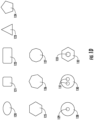
- Fig. 1D illustrates other cladding feature shapes that may be employed.
- the cross-section of the cladding feature is not limited to circular shapes.
- Fig. 1D illustrates some other possible shapes 120-127, which can also be used.
- the configurations of the cladding feature, for example, the shape, dimension, material, refractive indexes, etc. of the cladding feature can vary.
- the variations are not limited to the perimeter of the cladding feature but can include further internal features and design as well.
- Cross-sections 128, 130 and 132 in Fig. 1-d show one or more inclusions with different refractive index 129, 131 and 133 than the material in which these inclusions are imbedded.
- These internal features can vary as well, for example, in shape, size, arrangement, material, refractive index, etc. Still other designs are possible.
- one or more of the cladding features can have shapes, dimensions, materials, and/or refractive indexes that are different from each other, e.g., not all of the cladding features need have the same design.
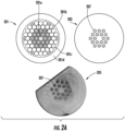
- Fig. 2A schematically illustrates an example of a large core, leakage channel fiber 203 and corresponding preform 201.
- the LCF 203 can be drawn from the preform 201.
- a portion of a fabricated LCF 205 is also shown.
- an LCF may be characterized by having a core and an inner cladding forming a first cladding region.
- One or more additional outer cladding regions may be utilized, for example, to guide pump light from a pump source.
- the core and inner cladding e.g., the first cladding region 103 may comprise glass having a refractive index n 1 .
- the inner cladding can include a background glass with refractive index n 1 and one or more cladding features with refractive indices smaller than n 1 .
- the cladding features may be all-glass or a combination of low index glass, gas (e.g., air), vacuum, or other lower index medium
- gas e.g., air
- the arrangement of low index cladding features provides leakage channels that provide higher loss for at least one higher-order mode relative to at least one lower-order mode (e.g., the fundamental mode).
- Confinement loss for all modes in the LCF core may, in some cases, be much larger than in a standard step index fiber.
- One advantage of the LCF is the differential loss between the fundamental mode and the next higher order mode may be large. Loss for the fundamental mode may be 0.05 dB/m to 2 dB/m while loss for the next higher order mode may be in the range 5 dB/m to 20 dB/m.
- the FM is guided while HOMs leak out to the fiber cladding.
- the background glass in an LCF is synthetic fused silica.
- the low index features 207 in Fig. 2A may include fluorine doped silica glass with a refractive index 1.2 ⁇ 10 -3 below that of fused silica.
- the low index features may be arranged in a few rings (e.g., 1, 2, 3, 4, or more rings), which may sometimes be referred to as layers, disposed about the core. In certain preferred implementations 2 or 3 rings may be utilized.
- the LCF 205 shown in Fig. 2A is arranged with two rings. In some embodiments, no more than 3 rings of low index features are utilized.
- the low index features have a periodicity A and a diameter d.
- the diameter d can represent the diameter of a circular feature or the maximum width of a non-circular feature.
- the ratio d/A is a parameter that may be used to characterize the leakage channel size. As will become apparent in the examples that follow the SAPs in an LCF may be characterized in part by having a pitch ⁇ p which is the distance from the center of a SAP to the nearest low index cladding feature.
- the ratio d/A for low index features arranged in a ring need not be uniform.
- the ratio d/ ⁇ p for SAPs arranged in a ring need not be uniform. Likewise, the ratio need not be uniform for each ring, e.g., the ratios d/A and/or d/ ⁇ p can be different for different rings.
- Polarization maintaining (PM) passive or active fibers may be utilized in fiber lasers/amplifiers where polarized light output is required.
- Leakage channel fibers can be polarization maintaining as discussed in ⁇ 742, for example as described with respect to at least Fig. 1C of ⁇ 742.
- SM standard single mode
- the core will only support a fundamental mode.
- the fundamental mode is degenerate for two orthogonal polarization states.
- these two degenerate states have identical propagation constants all along the fiber.
- a polarized light pulse propagating in the fiber would remain in the initial polarization state in this ideal case.
- a polarized light pulse travelling in the single mode fiber in one of these two degenerate states couples power into the other polarization state.
- the propagation constants are nearly equal between the two polarization states in SM fiber so coupling between the two states is facilitated.
- polarized light injected into a standard SM fiber will typically emerge un-polarized, partially polarized, elliptically polarized, or generally with a reduced polarization extinction ratio which is the power ratio in dB between the two output polarization axes.
- the fiber can be drawn with one or more stress applying parts (SAP)s, for example stress rods.
- SAP stress applying parts
- Stress-optic effects induced with the SAPs change the effective mode indices of the fundamental mode, and hence the propagation constants.
- the effective index of one polarization state is raised creating a "slow axis”.
- the effective index of the other polarization state is lowered creating a "fast axis”.
- the ability of random stress effects to cause mode coupling is reduced as a result of the increased difference in effective mode indices.
- Polarized light can be launched into an input of a PM fiber with its polarization axis parallel to the slow axis or parallel to the fast axis of the PM fiber. Both axes will guide light. Light arriving at the output of the PM fiber will have substantially the same polarization as at the input.
- a figure of merit for the system is the polarization extinction ratio (PER).
- a group of parameters include, for example, the difference ⁇ T between the coefficients of thermal expansion ⁇ T,SAP and ⁇ T,cladback of stress elements and the cladding background material, respectively; the minimum distance A between two neighboring micro-structural elements; the relative size of the micro-structural elements d/A; the difference between the core n core and cladding background n cladback refractive indices; the bending radius of the photonic crystal fiber; and combinations thereof.
- Such parameters may provide for tailoring of the polarizing bandwidth and its center wavelength to the particular application requirements. Control of the core and cladding background refractive indices allows the control of the mode field diameter thereby facilitating splicing to other micro-structured or non-micro-structured optical fibers.
- an LCF When compared to a PCF, a leakage channel fiber, with a preferred all-solid glass arrangement, may facilitate development of large mode fiber lasers and amplifiers.
- an LCF includes a large core surrounded with a few rings (e.g., 2 or 3) of relatively large air holes and provides a relatively high loss for higher order modes.
- a glass LCF includes a large core surrounded with a few rings of low index cladding features, for example a low index glass . The low index regions define narrow channels in the cladding glass.
- an all-glass LCF may be provided. Comparative examples of non-PM, PM, and polarizing (PZ) LCFs are discussed below.
- a leakage channel fiber (LCF) 203 is illustrated together with a corresponding preform stack 201 (from which the fiber 203 can be drawn), and image of an example of a fabricated fiber 205.
- the fiber may be characterized as a 50/480 LCF, corresponding to a 50 ⁇ m core and 480 ⁇ m diameter first (inner) cladding.
- the preform 201 includes a central solid rod 201a surrounded by two layers of low-index rods 201b.
- the rods 201b are composed of a core and a cladding.
- the core of a rod 201b is formed from material having a refractive index lower than the refractive index of the rod 201a.
- the cladding of a rod 201b is formed from a material having a refractive index identical to the material of rod 201a.
- the layers of low-index rods 201b are surrounded by two layers of solid rods 201c to form a cladding.
- the rods 201c comprise a material with the same refractive index as the core rod 201a.
- the rods 201a-201c are stacked inside an outer cladding tube 201d.
- the cladding tube 201d may have the same refractive index as the rods 201c.
- the microscope image illustrates the slightly different size of the cladding features of the inner and outer rings in the fabricated LCF 205. No SAPs are included and the fiber is non-PM in this example.
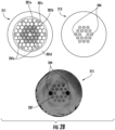
- Fig. 2B schematically illustrates examples of a preform 211 and fiber 213 corresponding to a large core polarization maintaining (PM) LCF, and includes a microscope image of an example corresponding fabricated large core PM LCF.
- the fiber is a 50/480 LCF having d/A with the same values as in Fig. 2A for the low index features.
- Two non-circular SAPs 204 in the outer ring are arranged with d/ ⁇ p ⁇ 0.9 and provide for PM operation, where d is the maximum diameter of the SAP and ⁇ p is the spacing between the center of the SAP 204 and the center of closest adjacent cladding feature
- a microscope image of a fabricated PM fiber 215 is shown.
- the SAPs are larger than the cladding features in the outer ring.
- the preform 211 is generally similar to the preform 201 but includes two SAP rods 201e in the outer ring of low-index rods 201c.
- the SAP rods 201e have coefficients of thermal expansion that are different from the coefficient of thermal expansion of the rods 201c that form the cladding and/or the rods 201b that form the low-index features.
- Figs. 3A-3B schematically illustrate examples of polarizing (PZ) LCFs 303, 313 together with respective examples of fabricated LCFs 305, 315.
- Each fiber is a 50/480 LCF having d/A with the same values as in Fig. 2A for low index features.
- Fig. 3B also shows an example of a preform 311 from which the fiber 313 can be drawn.
- the preform 311 is generally similar to the preform 211 but includes two stress applying rods 314.
- Fig. 4 schematically illustrates an example of a polarizing LCF preform 401 and an example of an LCF fiber 403 with an outermost cladding 405 configured as a pump guide.
- the background glass 402 surrounding the core and low index feature region has a higher refractive index than the surrounding glass 405.
- the NA of the background glass 402 relative to the surrounding glass 405 may be in the range 0.1-0.3 to form the pump guide.
- the fiber is a 50/480 LCF.
- a rare-earth doped core region (not separately shown) surrounded by the SAPs 404 and the inner layer of low index features may be formed to provide the 50/200 leakage channel gain fiber.
- Such a PZ LCF may be utilized in a fiber amplifier or fiber laser system.
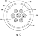
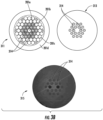
- Fig. 5 schematically illustrates an example of an arrangement of polarizing LCF 503 in which a single ring 502 of twelve low index cladding features for leakage channels are arranged in a nearly circular configuration.
- the low index features (and leakage channels) are not arranged in a hexagonal pattern but more closely approximates a circle (e.g., a 12-sided polygon).
- the diameter of each of the two SAPs 504 is larger than the core diameter, and much larger than the diameter of the low index cladding features, for example about 5-10 times larger in this example.
- a polarizing leakage channel fiber may be constructed based on the following principles and actions.
- a cladding glass with refractive index n 1 and thermal expansion coefficient (TEC) ⁇ clad A cladding diameter and core diameter is specified.
- NA numerical aperture
- FM fundamental mode
- a cladding size is chosen to match the target core diameter so that the cladding isolates the core from exterior stress.
- the total outer cladding diameter is to be large enough to isolate the core from external stress.
- the core diameter may be in the range from about, 20-150 ⁇ m, 35-150 ⁇ m, or 50-150 ⁇ m.
- the outer cladding is to be at least three times the core size.
- the core to cladding ratio may be 50/250 or 50/480.
- a preferred cladding diameter may be relatively increased.
- a preferred outer cladding diameter may be at least about 500 ⁇ m and up to about 1 mm.
- a pump guide may be implemented and considered separately from the total cladding diameter.
- a 150 ⁇ m diameter pump guide may surround a 50 ⁇ m diameter core.
- the fiber may have a 500 ⁇ m diameter outer cladding.
- the fiber may be doped with a dopant to provide gain so that it can serve as an active fiber, e.g., in a laser or amplifier.
- the LCF core refractive index, relative to n 1 is in the range (n 1 +1 ⁇ 10 -4 ) to (n 1 -2 ⁇ 10 -4 ).
- ⁇ core ⁇ ⁇ clad where ⁇ is the thermal expansion coefficient (TEC) of the respective core or cladding region.
- the low index glass regions arranged around the core have refractive indices smaller than n 1 .
- the TEC of the low-index regions is within about +/- 20% of ⁇ clad .
- the TEC of the low-index regions may exceed 7x10 and may be as large as about 3 ⁇ 10 -6 .
- the magnitude of index differences, Idnl, between each of the low index glass regions and n 1 may be approximately Idnl >5 ⁇ 10 -4 .
- the index difference may be larger, e.g., Idnl ⁇ 1.2 ⁇ 10 -3 .
- at least two of the low index features can be arranged as SAPs and composed of a glass with TEC ⁇ SAP , where
- two SAP regions can be placed adjacent to and symmetrically about the core.
- the SAPs can be included in an inner ring, whereas the LCF may have 1-4 rings of low-index features. In some embodiments, up to about 8 rings may be utilized, or up to about 10 rings in other embodiments.
- Any of the fiber embodiments disclosed herein can include portions that are active and comprise one or more regions doped with a gain medium to provide optical gain.
- PZ active or passive fibers may have R sc in the range from about 0.7 - 0.95, and may exceed 1, and the invention is up to 1.5.
- PZ fibers tend to have R sc larger than PM fibers.
- PM behavior can be obtained having Rsc in the range from 0.4 to 0.7.
- PZ behavior can be obtained for fibres according to the invention having R sc greater than about 0.7 and up to about 1.5.
- Passive PZ fibers may be fabricated with R sc over a somewhat wider range than active PZ fibers.
- Various embodiments of glass polarizing LCF (PZ-LCF) fiber can provide one or more favorable characteristics.
- cladding features may be large and arranged with large pitch, with fewer preform stack elements than required for fabrication of a conventional PCF. As such, fabrication is facilitated.
- fewer stress applying part materials are required.
- a 40/200 PCF may utilize more than 20 SAP material regions.
- some of the PZ-LCF embodiments disclosed herein include as few as two SAP regions.
- bending constraints and bend performance are parameters to consider. Applicants also have discovered that for a variety of fabricated fibers, no preferred bend orientation was found to achieve best performance in passive fibers, nor is any advantage expected in polarizing applications for non-circular fiber shapes.
- a cladding material may include fused silica.
- a cladding material may include one or a combination of pyrex, soda-lime glass, phosphate glass, chalcogenide glass, fluoride glass, or a polymer, preferably with high index uniformity.
- a cladding material may include a single crystal material.
- the refractive index n1 of a cladding material may in the range from greater than 1 to about 3.5 at a wavelength of operation, for example from the near infrared (IR) to mid-IR.
- the LCF fiber can include a second cladding substantially surrounding the first cladding.
- a second cladding material may include fluorine-doped silica glass or boron-doped silica glass.
- a second cladding material index of refraction, n2 may be less than n1, on the average.
- the second cladding material refractive index n2 may be in the range from greater than 1.0 to less than about n1, for example up to about n1 - 5 ⁇ 10 -5 .
- Multicore PM and/or PZ LCF fibers as described above, including arrangements with multiple rings of cladding features, may be utilized in active or passive multicore fibers.
- Multicore PM or PZ fibers may be utilized in high peak power applications in which an input pulse is divided into a plurality of spatially separated beams which are individually amplified. The beams are recombined following amplification.
- Such configurations provide for increased peak power useful for medical and industrial applications, and may be utilized with conventional fiber laser/amplifier technology, specialty fibers (e.g.: LCF, PCF), optical parametric oscillator/amplifiers, or combinations thereof.
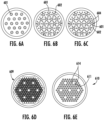
- Fig. 6A is a cross sectional view schematically illustrating an example of a multicore fiber comprising individual fiber cores based on step index fiber.
- Fig. 6B is a cross sectional view schematically illustrating an example of a multicore fiber comprising individual fiber cores based on leakage channel fiber.
- Fig. 6C is a cross sectional view schematically illustrating an example of a multicore fiber comprising individual fiber cores based on polarization maintaining leakage channel fiber.
- Fig. 6E is a cross sectional view schematically illustrating an example of a polarizing leakage channel fiber with 2 layers (PZ-LCF), with its preform illustrated in Fig. 6D .
- PZ-LCF polarizing leakage channel fiber with 2 layers
- the '398 patent provides, among other things, examples of active multicore fibers having individual fiber cores based on leakage channel fiber.
- Figs 6A-6C (which correspond to Figs. 3A -3C of ⁇ 398) illustrate multicore fibers comprising individual fiber cores 601. Each multi-core fiber includes 19 individual single-mode cores in these examples.
- FIG. 6B and 6C illustrate active multicore Leakage Channel fibers (MC-LCF) .
- the shaded circles 601 represent the core areas, at least some of which, in this example, are (optionally) doped with a dopant such as a rare earth ion (e.g., Yb) whereas the small non-shaded circles 602 represent air-holes or glass areas with reduced refractive index compared to the cores 601 and/or material surrounding the low-index areas 602.
- a dopant such as a rare earth ion (e.g., Yb)
- the small non-shaded circles 602 represent air-holes or glass areas with reduced refractive index compared to the cores 601 and/or material surrounding the low-index areas 602.
- six features 602, 604 surround each of the cores 601.
- a different number of cores 601 and/or a different number of features 602, 604 can be used.
- passive fibers do not
- multicore leakage channel fibers may allow tighter packing of the cores compared to conventional step-index multicore single-mode fibers with less mode-coupling because of the reduction or minimization of the modal wings of each individual mode.
- the wings of the intensity distribution of the leakage channel fiber go down to zero much faster than in conventional step-index fibers.
- any substantial thermally induced phase fluctuations are to be considered in multicore fibers, particularly for applications utilizing ultrashort pulses.
- Such thermal fluctuations may be compensated by the introduction of appropriate phase delays introduced before or after the fiber.
- phase delays can for example be implemented with optical phase plates of a certain thickness.
- an adaptive optics compensation scheme can adjust for the path length difference.
- the amplifiers of the array may be spaced such that thermal fluctuations of the amplifiers are matched sufficiently to limit relative phase fluctuations at amplifier outputs to a bandwidth, for example less than 10 kHz, and such that optical energy coupling between any of the amplifiers is small or negligible. Examples of such implementations are discussed in ⁇ 398.
- Multicore gain fibers can also be manufactured in an all polarization maintaining (PM) configuration.
- Fig. 6C illustrates an example of a PM design. The fiber is similar to the structure of the fiber shown in Fig. 6B , but for the additional incorporation of stress producing regions.
- SAPs 604 are disposed on opposite sides of the cores.
- the stress producing regions correspond to two of six features immediately surrounding each core. The regions produce stress in the fiber core and lead to polarization maintaining operation.
- the core separation can be increased and/or more than one low index feature can be disposed between two core regions as will be discussed below.
- none, some, or all of the cores 601 can be doped with a dopant to provide optical gain.
- Multicore fibers for use in either active of passive applications, may also be manufactured in a polarizing configuration.
- Arrangements in which SAPs are configured with increased distance from the core can result in PM operation rather than polarizing operation.
- polarizing (PZ) operation can be obtained.
- PZ fibers tend to have R sc larger than PM fibers.
- PM behavior can be obtained for fibres having R sc in the range from 0.4 to 0.7.
- PZ behavior can be obtained for fibres according to the invention having R sc greater than about 0.7 and up to about 1.5.
- Passive PZ fibers may be fabricated with R sc over a somewhat wider range than active PZ fibers.
- Fig. 6E illustrates an example of a multicore fiber 610 (its preform 609 is shown in Fig. 6D ) with seven (7) core regions 611 each surrounded by two (2) rings of low index cladding features.
- the two rings surrounding at least some of the core regions 611 contains two SAPs 614 arranged such that the SAPs are adjacent to or in close proximity to the cores for PZ capability.
- none, some, or all of the core regions 611 can be doped.
- the fiber 610 may be modified with doped core regions having a dimension, for example maximum diameter, in the range of about 35-100 ⁇ m in order to construct a large core leakage channel, polarizing fiber.
- a core size greater than about 20 ⁇ m may be utilized, e.g., from about 20-100 ⁇ m
- multicore fibers and applications thereof are discussed in ⁇ 398.
- double-clad, multicore rare-earth doped (e.g., Yb) amplifiers may be used to generate high peak power.
- coaxial multicore fiber arrangements may include a single circular array of cores near the periphery of the fiber at least partially surrounded by low index cladding features (not shown).
- Figs. 7A-7B illustrates an example of a preform 701 ( Fig. 7A ) for a polarizing LCF and a corresponding example of a portion of a fabricated LCF 703 ( Fig. 7B).
- Figure 7B is a microscope image of 50/450 polarizing LCF 703 cleaved end facet. Dark regions 705 are fluorine or boron doped low index glass.
- the LCF fiber 703 shown in Fig. 7B was fabricated via the stack and draw method.
- a stack of cladding rods 701a, rods with low index cores 701b, and SAP rods 701c was arranged around a core rod 701d and stacked inside an outer tube 701e in the geometry shown in the preform 701 of Fig. 7A .
- preform 701 there are five layers in the stack, where the center rod is counted as layer one.
- Layers two and three of the preform stack include low index features 701b.
- Layer four has 18 rods 701a of background cladding glass.
- Layer five has 24 rods 701a of background cladding glass.
- the corner rods in layer five shown intersecting with the inner wall of the cladding tube were removed from the stack in stages while the ends of the remaining rods were fused together to create a bundle.
- the bundle was inserted in the cladding tube.
- the assembled fiber preform was brought to the draw tower.
- the preform 701 was drawn under vacuum to a cladding diameter of 450+/-5 um.
- a protective high index polymer coating was applied and the fabricated fiber 703 was wound on a reel to form a coil.
- Bend loss, M 2 , and polarization extinction ratio (PER) as a function of coil diameter were measured with a four meter length of fiber.
- the input beam wavelength was 1040 nm.
- a cut-back measurement was performed which indicated the FM background loss in the core was ⁇ 0.3 dB/m.
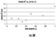
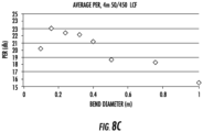
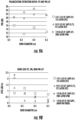
- Figs. 8A-8D are plots illustrating performance of the polarizing LCF of Fig. 7B .
- This example fiber was not PM but was linearly polarizing.
- Fig. 8A illustrates bend loss for a four meter length of 50/450 polarizing LCF. Bend loss is similar for non-PM LCF versions with similar structure parameters. Bend loss is large compared to a step index fiber.
- Fig. 8B illustrates M2 measurements for a length of polarizing 50/450 LCF.
- the fiber M2 was less than about 1.2, and in the range from about 1.05 to about 1.2.
- Fig.8C illustrates polarization extinction ratio (PER) measurements from the output of a four meter length of 50/450 polarizing LCF.
- PER polarization extinction ratio
- Fig. 8D illustrates the polarizing characteristic of the LCF.
- four meters of fiber were utilized, with a coil diameter of 160 mm.
- An input half-waveplate (WP) was rotated to match the polarizing axis of the fiber.
- An output half- waveplate was scanned to measure the output variation. The input waveplate was rotated by 45 degrees and the output waveplate was scanned to yield measurements close to zero output for all waveplate angles. This quantitatively illustrates the polarizing property of this example LCF.
- Figs. 9A-9C are plots illustrating performance of additional examples of fabricated LCFs having two layers and various arrangements of stress applying parts (SAPs) therein.
- the PM fiber in the following examples corresponds to the fabricated fiber 215 of Fig. 2B , with relatively large SAPs, d/ ⁇ p ⁇ 0.9.
- the two PZ fibers correspond to the fabricated fibers 305, 315 of Figs. 3A and 3B , with SAPs having d/ ⁇ p ⁇ 0.9 and 0.75, respectively.
- Fig. 9A illustrates the PERs of the three fibers as a function of bend diameter.
- bend diameters less than about 0.4 m the PM fiber exhibited the highest PER.
- the larger SAPs corresponding to d/ ⁇ p ⁇ 0.9, resulted in the largest extinction with the PM fibers and SAPs in the outer layer.
- the lowest extinction was found with the PZ fiber with SAPs in the innermost layer, adjacent to the core.
- reducing the SAP dimension improved the relative PER.
- Fig 9B illustrates bend loss performance as a function of coil diameter.
- the loss in total power was determined, without consideration of the modes.
- a non-PM fiber measurement was also included.
- the non-PM configuration exhibited the highest loss at smaller bend diameters. Also, among the PZ and PM fibers, the higher PER resulted in increased loss with smaller bend diameters.
- Fig. 9C illustrates M 2 measurements for the PZ fibers, PM fiber, and a non-PM fiber.
- the M 2 value was in the range of about 1.05-1.3 for the PZ fiber with reduced SAP dimension (d/ ⁇ p ⁇ 0.75), whereas M 2 ⁇ 1.7 was obtained for the larger SAPs.
- the larger value may be associated with increased higher order mode content induced narrowing of some of the leakage channels by the large size of the SAPs adjacent to the core.
- each PZ SAP was in the inner ring proximate to the core.
- the measurements of Fig. 9C were obtained at a wavelength of 1040 nm. It was observed that the M 2 measurement improved somewhat at a longer wavelength of 1.55 ⁇ m.
- d/ ⁇ p in a preferred range from about 0.4-.0.75 may provide for desirable M 2 less than about 1.3, with bend diameters in the range from about 0.2 - 0.6 m.
- M may be in the range from about 1.05-1.7 with bend diameters in the range from about 0.2 - 0.6 m.
- SAPs in the innermost layer, adjacent to the core may be adjusted to effectively reduce d/A of the SAPs while maintaining the larger SAP size. For example, fewer cladding features may be utilized and/or the spacing between cladding features may be increased. With such implementations the overall shape of the mode field may become slightly elliptical.
- Figs.10A-10B are plots comparing polarization maintaining capability of examples of PZ and PM fibers, respectively.
- PZ or PM fiber arrangements may be utilized as passive (transmission) fibers or as fiber compressors in ultrashort pulse laser systems. In such systems a temporally broadened pulse or other pulse in the picosecond to nanosecond range can be compressed to a shorter pulse width. In some implementations the well-known chirped pulse amplification technique may be utilized.
- a 1.4 m length of fiber was employed at a signal wavelength near 1.5 um to compress input pulses of duration 2.46 ps to shorter pulses 57 fs long.
- Input PER was 32 dB.
- Output PER was 21 dB.
- compressed pulse widths as short as about 50 fs, 100 fs, or 1 ps may be provided. In some embodiments, pulse widths below 100 fs may be generated.
- input light with PER of 26 dB was launched into 900 m of SM PM fiber.
- the PER at the output was 21 dB.
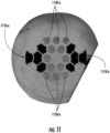
- a polarizing leakage channel fiber with an index matched Yb-doped core was fabricated.
- An image of a portion of the fiber cross section is shown in Fig. 11 .
- the fiber was fabricated with a total of eight SAP elements.
- the SAP elements were arranged in two groups of four (1110-a, 1110-b). In a group of four, three SAPs are in layer #3 and one SAP is in layer #4 where layer #1 is the fiber core.
- Layer #4 is mostly silica glass except for the two SAPs.
- the average waveguide core diameter is 50 um while the average cladding diameter is 400 um.
- the cladding was made slightly hexagonal to facilitate pump absorption.
- the fiber was drawn with a low index polymer coating. In one configuration a four meter length of the fiber was coiled to a diameter of 0.5 m. The orientation of the fiber was controlled such that the axis defined by the SAP groups was perpendicular to the plane of the coil. Fiber ends were angle polished to about 5° and ferruled.
- Pulses from a fiber laser were injected into one end of the LCF from a SM fiber using free space coupling.
- Average input power was about 24 mW with about 26 dB PER at a center wavelength near 1040 nm.
- Input pulse repetition rate was about 50 MHz.
- Pump light at 980 nm from a high power laser diode was free space coupled into the other end of the fiber.
- Output PER was about 18.8 dB with M 2 ⁇ 1.2.
- Signal light injected into one polarization axis of the fiber was amplified.
- Signal light injected into the other (orthogonal) polarization axis was not amplified or significantly guided.
- a low-level background was observed in the orthogonal polarization axis which may have resulted from amplified spontaneous emission (ASE) originating from the unidirectional pumping arrangement.
- ASE amplified spontaneous emission
- This example demonstrates capability of selectively amplifying polarized input pulses in such a way as to output pulses having substantially a single polarization and a high extinction ratio.
- PER at the amplifier output in the range of about 15 dB to about 25 dB may be obtained.
- the polarized output pulses exhibited good beam quality, as exemplified with M 2 in the range from about 1.05 to less than about 1.2, and below about 1.8.
- a commercial finite element analysis program was utilized (RSoft FemSIM available from Synopsys, Inc.) to calculate mode profiles and effective mode indices, n eff , for non-PM and PM LCF.
- the software allowed the user to simulate the effects of thermally induced stress on n eff of the fundamental mode transverse electric (TE) and transverse magnetic (TM) polarization states.
- B may be used as a good proxy for predicting PM/PZ fiber PER. Without considering other perturbations on the system, or details of a fiber's index profile, values of B>0 lead to PM behavior while larger values of B lead to polarizing behavior.
- B values for these examples of PM/PZ LCF are low.
- the model indicates there is a transition range for PM ⁇ PZ where if B is less than about 7 ⁇ 10 -5 the fiber is PM. If B greater than about 8 ⁇ 10 -5 the LCF is PZ.
- the modal birefringence of the Yb-doped core, polarizing, LCF fiber amplifier of the above example was estimated, which led to an prediction of PZ behavior for the active fiber.
- EXAMPLE index uniformity of cladding material.
- index uniformity In the fabrication of large core fibers index uniformity is to be considered.
- U.S. Patent 7,450,813 entitled “Rare earth doped and large effective are optical fibers for fiber lasers and amplifiers" discloses effects of index non-uniformity.
- ⁇ 813 discusses effects of index non-uniformity, including formation of localized waveguides, and identifies methods for obtaining index uniformity. See '813, at least at columns 5:28-6:34.
- the uniformity of the cladding material surrounding the core can be better than about 5 ⁇ 10 -5 , about 1 ⁇ 10 -5 , or better than about 5 ⁇ 10 -6 .
- At least one of: A, B, or C is intended to cover: A, B, C, A and B, A and C, B and C, and A, B, and C.
- Conjunctive language such as the phrase "at least one of X, Y and Z," unless specifically stated otherwise, is otherwise understood with the context as used in general to convey that an item, term, etc. may be at least one of X, Y or Z. Thus, such conjunctive language is not generally intended to imply that certain embodiments require at least one of X, at least one of Y, and at least one of Z to each be present.
- Such operating regimes and desired results are not limited solely to specific values of operating parameters, conditions, or results shown, for example, in a table, graph, plot, figure, or photograph, but also include suitable ranges including or spanning these specific values. Accordingly, the values disclosed herein include all of the values in the range between any of the values (or upper or lower limits) listed or shown in the tables, graphs, plots, figures, photographs, etc. Additionally, the values disclosed herein include the range of values above or below any of the values listed or shown in the tables, graphs, plots, figures, photographs, etc. as might be demonstrated by other values listed or shown in the tables, graphs, plots, figures, photographs, etc.
- the data disclosed herein may establish one or more effective operating ranges and/or one or more desired results for certain embodiments, it is to be understood that not every embodiment need be operable in each such operating range or need produce each such desired result. Further, other embodiments of the disclosed fibers may be configured differently or operate in other operating regimes and/or produce other results than shown and described with reference to the example experiments, experimental data, tables, graphs, plots, photographs, figures, and other data herein.
Landscapes
- Physics & Mathematics (AREA)
- General Physics & Mathematics (AREA)
- Optics & Photonics (AREA)
- Lasers (AREA)
Applications Claiming Priority (2)
| Application Number | Priority Date | Filing Date | Title |
|---|---|---|---|
| US201361907754P | 2013-11-22 | 2013-11-22 | |
| PCT/US2014/064066 WO2015077021A1 (en) | 2013-11-22 | 2014-11-05 | Polarizing and polarization maintaining leakage channel fibers |
Publications (2)
| Publication Number | Publication Date |
|---|---|
| EP3072002A1 EP3072002A1 (en) | 2016-09-28 |
| EP3072002B1 true EP3072002B1 (en) | 2024-05-22 |
Family
ID=51947488
Family Applications (1)
| Application Number | Title | Priority Date | Filing Date |
|---|---|---|---|
| EP14802547.1A Active EP3072002B1 (en) | 2013-11-22 | 2014-11-05 | Polarizing and polarization maintaining leakage channel fibers |
Country Status (5)
| Country | Link |
|---|---|
| US (1) | US10036850B2 (da) |
| EP (1) | EP3072002B1 (da) |
| JP (1) | JP6657087B2 (da) |
| DK (1) | DK3072002T3 (da) |
| WO (1) | WO2015077021A1 (da) |
Families Citing this family (28)
| Publication number | Priority date | Publication date | Assignee | Title |
|---|---|---|---|---|
| DK3072002T3 (da) | 2013-11-22 | 2024-08-05 | Imra America Inc | Polariserende og polarisationsopretholdende lækagekanalfibre |
| CN106458697B (zh) | 2014-01-30 | 2020-06-30 | 恩耐公司 | 旋转的圆形芯部光纤 |
| JP6226905B2 (ja) * | 2015-03-30 | 2017-11-08 | 株式会社フジクラ | マルチコア光ファイバ、及び、マルチコア光ファイバの製造方法 |
| CN111239889A (zh) | 2015-06-25 | 2020-06-05 | Nkt光子学有限公司 | 传输光纤组件和宽带光源 |
| WO2017072750A1 (en) * | 2015-11-01 | 2017-05-04 | Goldin Shlomo Yehuda | Optical fiber based on a transmission anti-resonance in the cladding |
| US10261246B2 (en) | 2016-12-14 | 2019-04-16 | Ofs Fitel, Llc | Polarization-maintaining fiber device supporting propagation in large mode field diameters |
| US11156769B2 (en) | 2016-12-14 | 2021-10-26 | Ofs Fitel, Llc | Polarization-maintaining fiber device supporting propagation in large mode field diameters |
| WO2018169487A1 (en) * | 2017-03-14 | 2018-09-20 | Nanyang Technological University | Fiber preform, optical fiber and methods for forming the same |
| DE102017121147A1 (de) * | 2017-09-04 | 2019-03-07 | Fraunhofer-Gesellschaft zur Förderung der angewandten Forschung e.V. | Erzeugung von Mehrfach-Laserpulsen durch Überlagerung von Laserstrahlung |
| US11353650B2 (en) * | 2018-03-30 | 2022-06-07 | Nlight, Inc. | Single mode LMA (large mode area) fiber |
| CN108459371B (zh) * | 2018-04-04 | 2020-05-12 | 长飞光纤光缆股份有限公司 | 一种掺镱保偏光纤 |
| US10466412B1 (en) | 2018-08-31 | 2019-11-05 | Nexans | Selective mode suppressing multi-mode fiber optic cable for increased bandwidth |
| US11327250B1 (en) * | 2019-03-08 | 2022-05-10 | Wavefront Research, Inc. | Optical interconnect devices |
| CN111892291B (zh) * | 2019-05-06 | 2022-12-23 | 宁波大学 | 全固态光子晶体光纤预制棒的挤压制备方法 |
| US11462878B2 (en) * | 2019-05-23 | 2022-10-04 | Lawrence Livermore National Security, Llc | All solid hybrid arrow fiber |
| CN110261955A (zh) * | 2019-06-20 | 2019-09-20 | 长飞光纤光缆股份有限公司 | 一种保偏多芯光纤 |
| CN110261956B (zh) * | 2019-06-20 | 2021-02-26 | 长飞光纤光缆股份有限公司 | 一种阵列型保偏多芯光纤 |
| JP7584258B2 (ja) * | 2019-09-16 | 2024-11-15 | ルーメンタム オペレーションズ エルエルシー | 回転光ビーム発生装置 |
| WO2021183846A1 (en) * | 2020-03-13 | 2021-09-16 | Ofs Fitel, Llc | System for measuring microbends and arbitrary micro-deformations along a three-dimensional space |
| CN111635126A (zh) * | 2020-04-21 | 2020-09-08 | 艾菲博(宁波)光电科技有限责任公司 | 一种多芯单模/多芯少模通信光纤的制备工艺及制备装置 |
| CN115735305A (zh) * | 2020-08-17 | 2023-03-03 | 古河电气工业株式会社 | 光放大光纤、光纤放大器以及光通信系统 |
| JP7558710B2 (ja) * | 2020-08-17 | 2024-10-01 | 古河電気工業株式会社 | 光結合器、光増幅器及び通信システム |
| CN114185126B (zh) * | 2020-09-14 | 2025-10-21 | 中国科学院上海光学精密机械研究所 | 多芯保偏光子晶体光纤 |
| JP7528712B2 (ja) * | 2020-10-16 | 2024-08-06 | 住友電気工業株式会社 | マルチコア光ファイバおよびマルチコア光ファイバケーブル |
| CN119768717A (zh) * | 2022-09-07 | 2025-04-04 | 住友电气工业株式会社 | 偏振保持光纤及偏振保持光纤的制造方法 |
| CN115826127B (zh) * | 2022-11-23 | 2023-06-20 | 华北理工大学 | 金覆膜d型微结构光纤大容差偏振滤波器 |
| EP4524626A1 (en) * | 2023-09-13 | 2025-03-19 | NKT Photonics A/S | Polarization maintaining photonic crystal fibre |
| CN118409388A (zh) * | 2024-06-24 | 2024-07-30 | 中国工程物理研究院激光聚变研究中心 | 一种具有低折射率区域的保偏光纤 |
Citations (1)
| Publication number | Priority date | Publication date | Assignee | Title |
|---|---|---|---|---|
| US20070266738A1 (en) * | 2006-05-19 | 2007-11-22 | Michael Thomas Gallagher | Method of making an optical fiber |
Family Cites Families (13)
| Publication number | Priority date | Publication date | Assignee | Title |
|---|---|---|---|---|
| US6954575B2 (en) | 2001-03-16 | 2005-10-11 | Imra America, Inc. | Single-polarization high power fiber lasers and amplifiers |
| EP1700146B1 (en) | 2003-12-19 | 2013-04-10 | NKT Photonics A/S | Photonic crystal fibres comprising stress elements |
| US7724422B2 (en) | 2004-01-30 | 2010-05-25 | Nufern | Method and apparatus for providing light having a selected polarization with an optical fiber |
| US7787729B2 (en) | 2005-05-20 | 2010-08-31 | Imra America, Inc. | Single mode propagation in fibers and rods with large leakage channels |
| JP2008078629A (ja) * | 2006-09-20 | 2008-04-03 | Imra America Inc | ファイバ・レーザおよびファイバ増幅器用の希土類がドープされ有効区域が大きい光ファイバ |
| US7450813B2 (en) | 2006-09-20 | 2008-11-11 | Imra America, Inc. | Rare earth doped and large effective area optical fibers for fiber lasers and amplifiers |
| DK2082462T3 (da) | 2007-04-06 | 2014-11-24 | Fujikura Ltd | Fotonisk båndgabsfiber og fiberforstærker |
| WO2009042347A1 (en) | 2007-09-26 | 2009-04-02 | Imra America, Inc. | Glass large-core optical fibers |
| US8199398B2 (en) * | 2008-02-07 | 2012-06-12 | Imra America, Inc. | High power parallel fiber arrays |
| WO2010065788A1 (en) * | 2008-12-04 | 2010-06-10 | Imra America, Inc. | Highly rare-earth-doped optical fibers for fiber lasers and amplifiers |
| US8526773B2 (en) * | 2010-04-30 | 2013-09-03 | Corning Incorporated | Optical fiber with differential birefringence mechanism |
| FR2974637B1 (fr) * | 2011-04-26 | 2013-11-15 | Cnrs Ct Nat De Rech Scient | Fibre optique monomode a triple gaine |
| DK3072002T3 (da) | 2013-11-22 | 2024-08-05 | Imra America Inc | Polariserende og polarisationsopretholdende lækagekanalfibre |
-
2014
- 2014-11-05 DK DK14802547.1T patent/DK3072002T3/da active
- 2014-11-05 EP EP14802547.1A patent/EP3072002B1/en active Active
- 2014-11-05 JP JP2016533113A patent/JP6657087B2/ja active Active
- 2014-11-05 WO PCT/US2014/064066 patent/WO2015077021A1/en not_active Ceased
-
2016
- 2016-05-04 US US15/146,693 patent/US10036850B2/en active Active
Patent Citations (1)
| Publication number | Priority date | Publication date | Assignee | Title |
|---|---|---|---|---|
| US20070266738A1 (en) * | 2006-05-19 | 2007-11-22 | Michael Thomas Gallagher | Method of making an optical fiber |
Also Published As
| Publication number | Publication date |
|---|---|
| US10036850B2 (en) | 2018-07-31 |
| DK3072002T3 (da) | 2024-08-05 |
| EP3072002A1 (en) | 2016-09-28 |
| JP6657087B2 (ja) | 2020-03-04 |
| JP2017503189A (ja) | 2017-01-26 |
| US20160245989A1 (en) | 2016-08-25 |
| WO2015077021A1 (en) | 2015-05-28 |
Similar Documents
| Publication | Publication Date | Title |
|---|---|---|
| EP3072002B1 (en) | Polarizing and polarization maintaining leakage channel fibers | |
| US10353144B2 (en) | Glass large-core optical fibers | |
| US7526165B2 (en) | Optical coupler devices, methods of their production and use | |
| KR102784836B1 (ko) | 중공 코어 광섬유 및 레이저 시스템 | |
| EP2292566B1 (en) | Rare earth doped optical fibres and large effective area optical fibers for fiber lasers and amplifiers | |
| US8731356B2 (en) | Microstructured optical fibers and manufacturing methods thereof | |
| US10838141B2 (en) | Spun round core fiber | |
| US20230402808A1 (en) | Active lma optical fiber with enhanced transverse mode stability | |
| CN103703634B (zh) | 三重护套单模光纤 | |
| Yu et al. | Optical Fibers for High-Power Lasers |
Legal Events
| Date | Code | Title | Description |
|---|---|---|---|
| PUAI | Public reference made under article 153(3) epc to a published international application that has entered the european phase |
Free format text: ORIGINAL CODE: 0009012 |
|
| 17P | Request for examination filed |
Effective date: 20160513 |
|
| AK | Designated contracting states |
Kind code of ref document: A1 Designated state(s): AL AT BE BG CH CY CZ DE DK EE ES FI FR GB GR HR HU IE IS IT LI LT LU LV MC MK MT NL NO PL PT RO RS SE SI SK SM TR |
|
| AX | Request for extension of the european patent |
Extension state: BA ME |
|
| STAA | Information on the status of an ep patent application or granted ep patent |
Free format text: STATUS: REQUEST FOR EXAMINATION WAS MADE |
|
| DAX | Request for extension of the european patent (deleted) | ||
| STAA | Information on the status of an ep patent application or granted ep patent |
Free format text: STATUS: EXAMINATION IS IN PROGRESS |
|
| 17Q | First examination report despatched |
Effective date: 20191122 |
|
| GRAP | Despatch of communication of intention to grant a patent |
Free format text: ORIGINAL CODE: EPIDOSNIGR1 |
|
| STAA | Information on the status of an ep patent application or granted ep patent |
Free format text: STATUS: GRANT OF PATENT IS INTENDED |
|
| RIC1 | Information provided on ipc code assigned before grant |
Ipc: G02B 6/02 20060101ALI20230510BHEP Ipc: G02B 6/10 20060101ALI20230510BHEP Ipc: G02B 6/024 20060101ALI20230510BHEP Ipc: G02B 6/036 20060101AFI20230510BHEP |
|
| INTG | Intention to grant announced |
Effective date: 20230612 |
|
| GRAJ | Information related to disapproval of communication of intention to grant by the applicant or resumption of examination proceedings by the epo deleted |
Free format text: ORIGINAL CODE: EPIDOSDIGR1 |
|
| STAA | Information on the status of an ep patent application or granted ep patent |
Free format text: STATUS: EXAMINATION IS IN PROGRESS |
|
| INTC | Intention to grant announced (deleted) | ||
| GRAP | Despatch of communication of intention to grant a patent |
Free format text: ORIGINAL CODE: EPIDOSNIGR1 |
|
| STAA | Information on the status of an ep patent application or granted ep patent |
Free format text: STATUS: GRANT OF PATENT IS INTENDED |
|
| INTG | Intention to grant announced |
Effective date: 20240108 |
|
| GRAS | Grant fee paid |
Free format text: ORIGINAL CODE: EPIDOSNIGR3 |
|
| GRAA | (expected) grant |
Free format text: ORIGINAL CODE: 0009210 |
|
| STAA | Information on the status of an ep patent application or granted ep patent |
Free format text: STATUS: THE PATENT HAS BEEN GRANTED |
|
| AK | Designated contracting states |
Kind code of ref document: B1 Designated state(s): AL AT BE BG CH CY CZ DE DK EE ES FI FR GB GR HR HU IE IS IT LI LT LU LV MC MK MT NL NO PL PT RO RS SE SI SK SM TR |
|
| REG | Reference to a national code |
Ref country code: GB Ref legal event code: FG4D |
|
| REG | Reference to a national code |
Ref country code: CH Ref legal event code: EP |
|
| REG | Reference to a national code |
Ref country code: DE Ref legal event code: R096 Ref document number: 602014090220 Country of ref document: DE |
|
| REG | Reference to a national code |
Ref country code: IE Ref legal event code: FG4D |
|
| REG | Reference to a national code |
Ref country code: DK Ref legal event code: T3 Effective date: 20240802 |
|
| REG | Reference to a national code |
Ref country code: LT Ref legal event code: MG9D |
|
| REG | Reference to a national code |
Ref country code: NL Ref legal event code: MP Effective date: 20240522 |
|
| PG25 | Lapsed in a contracting state [announced via postgrant information from national office to epo] |
Ref country code: IS Free format text: LAPSE BECAUSE OF FAILURE TO SUBMIT A TRANSLATION OF THE DESCRIPTION OR TO PAY THE FEE WITHIN THE PRESCRIBED TIME-LIMIT Effective date: 20240922 |
|
| PG25 | Lapsed in a contracting state [announced via postgrant information from national office to epo] |
Ref country code: BG Free format text: LAPSE BECAUSE OF FAILURE TO SUBMIT A TRANSLATION OF THE DESCRIPTION OR TO PAY THE FEE WITHIN THE PRESCRIBED TIME-LIMIT Effective date: 20240522 |
|
| PG25 | Lapsed in a contracting state [announced via postgrant information from national office to epo] |
Ref country code: HR Free format text: LAPSE BECAUSE OF FAILURE TO SUBMIT A TRANSLATION OF THE DESCRIPTION OR TO PAY THE FEE WITHIN THE PRESCRIBED TIME-LIMIT Effective date: 20240522 Ref country code: FI Free format text: LAPSE BECAUSE OF FAILURE TO SUBMIT A TRANSLATION OF THE DESCRIPTION OR TO PAY THE FEE WITHIN THE PRESCRIBED TIME-LIMIT Effective date: 20240522 |
|
| PG25 | Lapsed in a contracting state [announced via postgrant information from national office to epo] |
Ref country code: GR Free format text: LAPSE BECAUSE OF FAILURE TO SUBMIT A TRANSLATION OF THE DESCRIPTION OR TO PAY THE FEE WITHIN THE PRESCRIBED TIME-LIMIT Effective date: 20240823 |
|
| PG25 | Lapsed in a contracting state [announced via postgrant information from national office to epo] |
Ref country code: PT Free format text: LAPSE BECAUSE OF FAILURE TO SUBMIT A TRANSLATION OF THE DESCRIPTION OR TO PAY THE FEE WITHIN THE PRESCRIBED TIME-LIMIT Effective date: 20240923 |
|
| REG | Reference to a national code |
Ref country code: AT Ref legal event code: MK05 Ref document number: 1689220 Country of ref document: AT Kind code of ref document: T Effective date: 20240522 |
|
| PG25 | Lapsed in a contracting state [announced via postgrant information from national office to epo] |
Ref country code: NL Free format text: LAPSE BECAUSE OF FAILURE TO SUBMIT A TRANSLATION OF THE DESCRIPTION OR TO PAY THE FEE WITHIN THE PRESCRIBED TIME-LIMIT Effective date: 20240522 |
|
| PG25 | Lapsed in a contracting state [announced via postgrant information from national office to epo] |
Ref country code: ES Free format text: LAPSE BECAUSE OF FAILURE TO SUBMIT A TRANSLATION OF THE DESCRIPTION OR TO PAY THE FEE WITHIN THE PRESCRIBED TIME-LIMIT Effective date: 20240522 |
|
| PG25 | Lapsed in a contracting state [announced via postgrant information from national office to epo] |
Ref country code: AT Free format text: LAPSE BECAUSE OF FAILURE TO SUBMIT A TRANSLATION OF THE DESCRIPTION OR TO PAY THE FEE WITHIN THE PRESCRIBED TIME-LIMIT Effective date: 20240522 |
|
| PG25 | Lapsed in a contracting state [announced via postgrant information from national office to epo] |
Ref country code: PL Free format text: LAPSE BECAUSE OF FAILURE TO SUBMIT A TRANSLATION OF THE DESCRIPTION OR TO PAY THE FEE WITHIN THE PRESCRIBED TIME-LIMIT Effective date: 20240522 |
|
| PG25 | Lapsed in a contracting state [announced via postgrant information from national office to epo] |
Ref country code: LV Free format text: LAPSE BECAUSE OF FAILURE TO SUBMIT A TRANSLATION OF THE DESCRIPTION OR TO PAY THE FEE WITHIN THE PRESCRIBED TIME-LIMIT Effective date: 20240522 |
|
| PG25 | Lapsed in a contracting state [announced via postgrant information from national office to epo] |
Ref country code: PT Free format text: LAPSE BECAUSE OF FAILURE TO SUBMIT A TRANSLATION OF THE DESCRIPTION OR TO PAY THE FEE WITHIN THE PRESCRIBED TIME-LIMIT Effective date: 20240923 Ref country code: PL Free format text: LAPSE BECAUSE OF FAILURE TO SUBMIT A TRANSLATION OF THE DESCRIPTION OR TO PAY THE FEE WITHIN THE PRESCRIBED TIME-LIMIT Effective date: 20240522 Ref country code: NO Free format text: LAPSE BECAUSE OF FAILURE TO SUBMIT A TRANSLATION OF THE DESCRIPTION OR TO PAY THE FEE WITHIN THE PRESCRIBED TIME-LIMIT Effective date: 20240822 Ref country code: NL Free format text: LAPSE BECAUSE OF FAILURE TO SUBMIT A TRANSLATION OF THE DESCRIPTION OR TO PAY THE FEE WITHIN THE PRESCRIBED TIME-LIMIT Effective date: 20240522 Ref country code: LV Free format text: LAPSE BECAUSE OF FAILURE TO SUBMIT A TRANSLATION OF THE DESCRIPTION OR TO PAY THE FEE WITHIN THE PRESCRIBED TIME-LIMIT Effective date: 20240522 Ref country code: IS Free format text: LAPSE BECAUSE OF FAILURE TO SUBMIT A TRANSLATION OF THE DESCRIPTION OR TO PAY THE FEE WITHIN THE PRESCRIBED TIME-LIMIT Effective date: 20240922 Ref country code: HR Free format text: LAPSE BECAUSE OF FAILURE TO SUBMIT A TRANSLATION OF THE DESCRIPTION OR TO PAY THE FEE WITHIN THE PRESCRIBED TIME-LIMIT Effective date: 20240522 Ref country code: GR Free format text: LAPSE BECAUSE OF FAILURE TO SUBMIT A TRANSLATION OF THE DESCRIPTION OR TO PAY THE FEE WITHIN THE PRESCRIBED TIME-LIMIT Effective date: 20240823 Ref country code: FI Free format text: LAPSE BECAUSE OF FAILURE TO SUBMIT A TRANSLATION OF THE DESCRIPTION OR TO PAY THE FEE WITHIN THE PRESCRIBED TIME-LIMIT Effective date: 20240522 Ref country code: ES Free format text: LAPSE BECAUSE OF FAILURE TO SUBMIT A TRANSLATION OF THE DESCRIPTION OR TO PAY THE FEE WITHIN THE PRESCRIBED TIME-LIMIT Effective date: 20240522 Ref country code: BG Free format text: LAPSE BECAUSE OF FAILURE TO SUBMIT A TRANSLATION OF THE DESCRIPTION OR TO PAY THE FEE WITHIN THE PRESCRIBED TIME-LIMIT Effective date: 20240522 Ref country code: AT Free format text: LAPSE BECAUSE OF FAILURE TO SUBMIT A TRANSLATION OF THE DESCRIPTION OR TO PAY THE FEE WITHIN THE PRESCRIBED TIME-LIMIT Effective date: 20240522 Ref country code: RS Free format text: LAPSE BECAUSE OF FAILURE TO SUBMIT A TRANSLATION OF THE DESCRIPTION OR TO PAY THE FEE WITHIN THE PRESCRIBED TIME-LIMIT Effective date: 20240822 |
|
| PG25 | Lapsed in a contracting state [announced via postgrant information from national office to epo] |
Ref country code: EE Free format text: LAPSE BECAUSE OF FAILURE TO SUBMIT A TRANSLATION OF THE DESCRIPTION OR TO PAY THE FEE WITHIN THE PRESCRIBED TIME-LIMIT Effective date: 20240522 |
|
| PG25 | Lapsed in a contracting state [announced via postgrant information from national office to epo] |
Ref country code: CZ Free format text: LAPSE BECAUSE OF FAILURE TO SUBMIT A TRANSLATION OF THE DESCRIPTION OR TO PAY THE FEE WITHIN THE PRESCRIBED TIME-LIMIT Effective date: 20240522 |
|
| PG25 | Lapsed in a contracting state [announced via postgrant information from national office to epo] |
Ref country code: RO Free format text: LAPSE BECAUSE OF FAILURE TO SUBMIT A TRANSLATION OF THE DESCRIPTION OR TO PAY THE FEE WITHIN THE PRESCRIBED TIME-LIMIT Effective date: 20240522 Ref country code: SK Free format text: LAPSE BECAUSE OF FAILURE TO SUBMIT A TRANSLATION OF THE DESCRIPTION OR TO PAY THE FEE WITHIN THE PRESCRIBED TIME-LIMIT Effective date: 20240522 |
|
| PG25 | Lapsed in a contracting state [announced via postgrant information from national office to epo] |
Ref country code: SM Free format text: LAPSE BECAUSE OF FAILURE TO SUBMIT A TRANSLATION OF THE DESCRIPTION OR TO PAY THE FEE WITHIN THE PRESCRIBED TIME-LIMIT Effective date: 20240522 |
|
| PG25 | Lapsed in a contracting state [announced via postgrant information from national office to epo] |
Ref country code: SM Free format text: LAPSE BECAUSE OF FAILURE TO SUBMIT A TRANSLATION OF THE DESCRIPTION OR TO PAY THE FEE WITHIN THE PRESCRIBED TIME-LIMIT Effective date: 20240522 Ref country code: SK Free format text: LAPSE BECAUSE OF FAILURE TO SUBMIT A TRANSLATION OF THE DESCRIPTION OR TO PAY THE FEE WITHIN THE PRESCRIBED TIME-LIMIT Effective date: 20240522 Ref country code: RO Free format text: LAPSE BECAUSE OF FAILURE TO SUBMIT A TRANSLATION OF THE DESCRIPTION OR TO PAY THE FEE WITHIN THE PRESCRIBED TIME-LIMIT Effective date: 20240522 Ref country code: EE Free format text: LAPSE BECAUSE OF FAILURE TO SUBMIT A TRANSLATION OF THE DESCRIPTION OR TO PAY THE FEE WITHIN THE PRESCRIBED TIME-LIMIT Effective date: 20240522 Ref country code: CZ Free format text: LAPSE BECAUSE OF FAILURE TO SUBMIT A TRANSLATION OF THE DESCRIPTION OR TO PAY THE FEE WITHIN THE PRESCRIBED TIME-LIMIT Effective date: 20240522 |
|
| PG25 | Lapsed in a contracting state [announced via postgrant information from national office to epo] |
Ref country code: IT Free format text: LAPSE BECAUSE OF FAILURE TO SUBMIT A TRANSLATION OF THE DESCRIPTION OR TO PAY THE FEE WITHIN THE PRESCRIBED TIME-LIMIT Effective date: 20240522 |
|
| REG | Reference to a national code |
Ref country code: DE Ref legal event code: R097 Ref document number: 602014090220 Country of ref document: DE |
|
| PLBE | No opposition filed within time limit |
Free format text: ORIGINAL CODE: 0009261 |
|
| STAA | Information on the status of an ep patent application or granted ep patent |
Free format text: STATUS: NO OPPOSITION FILED WITHIN TIME LIMIT |
|
| PG25 | Lapsed in a contracting state [announced via postgrant information from national office to epo] |
Ref country code: SI Free format text: LAPSE BECAUSE OF FAILURE TO SUBMIT A TRANSLATION OF THE DESCRIPTION OR TO PAY THE FEE WITHIN THE PRESCRIBED TIME-LIMIT Effective date: 20240522 |
|
| 26N | No opposition filed |
Effective date: 20250225 |
|
| REG | Reference to a national code |
Ref country code: CH Ref legal event code: PL |
|
| PG25 | Lapsed in a contracting state [announced via postgrant information from national office to epo] |
Ref country code: MC Free format text: LAPSE BECAUSE OF FAILURE TO SUBMIT A TRANSLATION OF THE DESCRIPTION OR TO PAY THE FEE WITHIN THE PRESCRIBED TIME-LIMIT Effective date: 20240522 |
|
| PG25 | Lapsed in a contracting state [announced via postgrant information from national office to epo] |
Ref country code: LU Free format text: LAPSE BECAUSE OF NON-PAYMENT OF DUE FEES Effective date: 20241105 |
|
| REG | Reference to a national code |
Ref country code: CH Ref legal event code: PL |
|
| GBPC | Gb: european patent ceased through non-payment of renewal fee |
Effective date: 20241105 |
|
| PG25 | Lapsed in a contracting state [announced via postgrant information from national office to epo] |
Ref country code: CH Free format text: LAPSE BECAUSE OF NON-PAYMENT OF DUE FEES Effective date: 20241130 |
|
| REG | Reference to a national code |
Ref country code: BE Ref legal event code: MM Effective date: 20241130 |
|
| PG25 | Lapsed in a contracting state [announced via postgrant information from national office to epo] |
Ref country code: SE Free format text: LAPSE BECAUSE OF FAILURE TO SUBMIT A TRANSLATION OF THE DESCRIPTION OR TO PAY THE FEE WITHIN THE PRESCRIBED TIME-LIMIT Effective date: 20240522 |
|
| PG25 | Lapsed in a contracting state [announced via postgrant information from national office to epo] |
Ref country code: BE Free format text: LAPSE BECAUSE OF NON-PAYMENT OF DUE FEES Effective date: 20241130 Ref country code: GB Free format text: LAPSE BECAUSE OF NON-PAYMENT OF DUE FEES Effective date: 20241105 |
|
| PG25 | Lapsed in a contracting state [announced via postgrant information from national office to epo] |
Ref country code: FR Free format text: LAPSE BECAUSE OF NON-PAYMENT OF DUE FEES Effective date: 20241130 |
|
| PG25 | Lapsed in a contracting state [announced via postgrant information from national office to epo] |
Ref country code: IE Free format text: LAPSE BECAUSE OF NON-PAYMENT OF DUE FEES Effective date: 20241105 |
|
| PGFP | Annual fee paid to national office [announced via postgrant information from national office to epo] |
Ref country code: DE Payment date: 20251126 Year of fee payment: 12 |
|
| PGFP | Annual fee paid to national office [announced via postgrant information from national office to epo] |
Ref country code: DK Payment date: 20251119 Year of fee payment: 12 |
|
| PG25 | Lapsed in a contracting state [announced via postgrant information from national office to epo] |
Ref country code: HU Free format text: LAPSE BECAUSE OF FAILURE TO SUBMIT A TRANSLATION OF THE DESCRIPTION OR TO PAY THE FEE WITHIN THE PRESCRIBED TIME-LIMIT; INVALID AB INITIO Effective date: 20141105 |