EP3071897B1 - Plate heat exchanger, in particular for condensing boilers - Google Patents
Plate heat exchanger, in particular for condensing boilers Download PDFInfo
- Publication number
- EP3071897B1 EP3071897B1 EP14828286.6A EP14828286A EP3071897B1 EP 3071897 B1 EP3071897 B1 EP 3071897B1 EP 14828286 A EP14828286 A EP 14828286A EP 3071897 B1 EP3071897 B1 EP 3071897B1
- Authority
- EP
- European Patent Office
- Prior art keywords
- plates
- heat exchanger
- channels
- iii
- level
- Prior art date
- Legal status (The legal status is an assumption and is not a legal conclusion. Google has not performed a legal analysis and makes no representation as to the accuracy of the status listed.)
- Active
Links
Images


Classifications
-
- F—MECHANICAL ENGINEERING; LIGHTING; HEATING; WEAPONS; BLASTING
- F24—HEATING; RANGES; VENTILATING
- F24H—FLUID HEATERS, e.g. WATER OR AIR HEATERS, HAVING HEAT-GENERATING MEANS, e.g. HEAT PUMPS, IN GENERAL
- F24H1/00—Water heaters, e.g. boilers, continuous-flow heaters or water-storage heaters
- F24H1/22—Water heaters other than continuous-flow or water-storage heaters, e.g. water heaters for central heating
- F24H1/44—Water heaters other than continuous-flow or water-storage heaters, e.g. water heaters for central heating with combinations of two or more of the types covered by groups F24H1/24 - F24H1/40
- F24H1/445—Water heaters other than continuous-flow or water-storage heaters, e.g. water heaters for central heating with combinations of two or more of the types covered by groups F24H1/24 - F24H1/40 with integrated flue gas condenser
-
- F—MECHANICAL ENGINEERING; LIGHTING; HEATING; WEAPONS; BLASTING
- F24—HEATING; RANGES; VENTILATING
- F24H—FLUID HEATERS, e.g. WATER OR AIR HEATERS, HAVING HEAT-GENERATING MEANS, e.g. HEAT PUMPS, IN GENERAL
- F24H8/00—Fluid heaters characterised by means for extracting latent heat from flue gases by means of condensation
-
- F—MECHANICAL ENGINEERING; LIGHTING; HEATING; WEAPONS; BLASTING
- F24—HEATING; RANGES; VENTILATING
- F24H—FLUID HEATERS, e.g. WATER OR AIR HEATERS, HAVING HEAT-GENERATING MEANS, e.g. HEAT PUMPS, IN GENERAL
- F24H1/00—Water heaters, e.g. boilers, continuous-flow heaters or water-storage heaters
- F24H1/22—Water heaters other than continuous-flow or water-storage heaters, e.g. water heaters for central heating
- F24H1/38—Water heaters other than continuous-flow or water-storage heaters, e.g. water heaters for central heating with water contained in separate elements, e.g. radiator-type element
-
- F—MECHANICAL ENGINEERING; LIGHTING; HEATING; WEAPONS; BLASTING
- F28—HEAT EXCHANGE IN GENERAL
- F28D—HEAT-EXCHANGE APPARATUS, NOT PROVIDED FOR IN ANOTHER SUBCLASS, IN WHICH THE HEAT-EXCHANGE MEDIA DO NOT COME INTO DIRECT CONTACT
- F28D21/00—Heat-exchange apparatus not covered by any of the groups F28D1/00 - F28D20/00
- F28D21/0001—Recuperative heat exchangers
- F28D21/0003—Recuperative heat exchangers the heat being recuperated from exhaust gases
- F28D21/0005—Recuperative heat exchangers the heat being recuperated from exhaust gases for domestic or space-heating systems
- F28D21/0007—Water heaters
-
- F—MECHANICAL ENGINEERING; LIGHTING; HEATING; WEAPONS; BLASTING
- F28—HEAT EXCHANGE IN GENERAL
- F28D—HEAT-EXCHANGE APPARATUS, NOT PROVIDED FOR IN ANOTHER SUBCLASS, IN WHICH THE HEAT-EXCHANGE MEDIA DO NOT COME INTO DIRECT CONTACT
- F28D9/00—Heat-exchange apparatus having stationary plate-like or laminated conduit assemblies for both heat-exchange media, the media being in contact with different sides of a conduit wall
- F28D9/0031—Heat-exchange apparatus having stationary plate-like or laminated conduit assemblies for both heat-exchange media, the media being in contact with different sides of a conduit wall the conduits for one heat-exchange medium being formed by paired plates touching each other
- F28D9/0043—Heat-exchange apparatus having stationary plate-like or laminated conduit assemblies for both heat-exchange media, the media being in contact with different sides of a conduit wall the conduits for one heat-exchange medium being formed by paired plates touching each other the plates having openings therein for circulation of at least one heat-exchange medium from one conduit to another
- F28D9/0056—Heat-exchange apparatus having stationary plate-like or laminated conduit assemblies for both heat-exchange media, the media being in contact with different sides of a conduit wall the conduits for one heat-exchange medium being formed by paired plates touching each other the plates having openings therein for circulation of at least one heat-exchange medium from one conduit to another with U-flow or serpentine-flow inside conduits; with centrally arranged openings on the plates
-
- F—MECHANICAL ENGINEERING; LIGHTING; HEATING; WEAPONS; BLASTING
- F28—HEAT EXCHANGE IN GENERAL
- F28F—DETAILS OF HEAT-EXCHANGE AND HEAT-TRANSFER APPARATUS, OF GENERAL APPLICATION
- F28F13/00—Arrangements for modifying heat-transfer, e.g. increasing, decreasing
- F28F13/06—Arrangements for modifying heat-transfer, e.g. increasing, decreasing by affecting the pattern of flow of the heat-exchange media
-
- F—MECHANICAL ENGINEERING; LIGHTING; HEATING; WEAPONS; BLASTING
- F28—HEAT EXCHANGE IN GENERAL
- F28F—DETAILS OF HEAT-EXCHANGE AND HEAT-TRANSFER APPARATUS, OF GENERAL APPLICATION
- F28F3/00—Plate-like or laminated elements; Assemblies of plate-like or laminated elements
- F28F3/02—Elements or assemblies thereof with means for increasing heat-transfer area, e.g. with fins, with recesses, with corrugations
- F28F3/04—Elements or assemblies thereof with means for increasing heat-transfer area, e.g. with fins, with recesses, with corrugations the means being integral with the element
- F28F3/042—Elements or assemblies thereof with means for increasing heat-transfer area, e.g. with fins, with recesses, with corrugations the means being integral with the element in the form of local deformations of the element
- F28F3/046—Elements or assemblies thereof with means for increasing heat-transfer area, e.g. with fins, with recesses, with corrugations the means being integral with the element in the form of local deformations of the element the deformations being linear, e.g. corrugations
-
- F—MECHANICAL ENGINEERING; LIGHTING; HEATING; WEAPONS; BLASTING
- F28—HEAT EXCHANGE IN GENERAL
- F28F—DETAILS OF HEAT-EXCHANGE AND HEAT-TRANSFER APPARATUS, OF GENERAL APPLICATION
- F28F3/00—Plate-like or laminated elements; Assemblies of plate-like or laminated elements
- F28F3/08—Elements constructed for building-up into stacks, e.g. capable of being taken apart for cleaning
- F28F3/086—Elements constructed for building-up into stacks, e.g. capable of being taken apart for cleaning having one or more openings therein forming tubular heat-exchange passages
-
- F—MECHANICAL ENGINEERING; LIGHTING; HEATING; WEAPONS; BLASTING
- F28—HEAT EXCHANGE IN GENERAL
- F28F—DETAILS OF HEAT-EXCHANGE AND HEAT-TRANSFER APPARATUS, OF GENERAL APPLICATION
- F28F9/00—Casings; Header boxes; Auxiliary supports for elements; Auxiliary members within casings
- F28F9/02—Header boxes; End plates
- F28F9/0219—Arrangements for sealing end plates into casing or header box; Header box sub-elements
- F28F9/0221—Header boxes or end plates formed by stacked elements
-
- F—MECHANICAL ENGINEERING; LIGHTING; HEATING; WEAPONS; BLASTING
- F28—HEAT EXCHANGE IN GENERAL
- F28D—HEAT-EXCHANGE APPARATUS, NOT PROVIDED FOR IN ANOTHER SUBCLASS, IN WHICH THE HEAT-EXCHANGE MEDIA DO NOT COME INTO DIRECT CONTACT
- F28D21/00—Heat-exchange apparatus not covered by any of the groups F28D1/00 - F28D20/00
- F28D2021/0019—Other heat exchangers for particular applications; Heat exchange systems not otherwise provided for
- F28D2021/0024—Other heat exchangers for particular applications; Heat exchange systems not otherwise provided for for combustion apparatus, e.g. for boilers
-
- F—MECHANICAL ENGINEERING; LIGHTING; HEATING; WEAPONS; BLASTING
- F28—HEAT EXCHANGE IN GENERAL
- F28F—DETAILS OF HEAT-EXCHANGE AND HEAT-TRANSFER APPARATUS, OF GENERAL APPLICATION
- F28F2255/00—Heat exchanger elements made of materials having special features or resulting from particular manufacturing processes
- F28F2255/08—Heat exchanger elements made of materials having special features or resulting from particular manufacturing processes pressed; stamped; deep-drawn
-
- Y—GENERAL TAGGING OF NEW TECHNOLOGICAL DEVELOPMENTS; GENERAL TAGGING OF CROSS-SECTIONAL TECHNOLOGIES SPANNING OVER SEVERAL SECTIONS OF THE IPC; TECHNICAL SUBJECTS COVERED BY FORMER USPC CROSS-REFERENCE ART COLLECTIONS [XRACs] AND DIGESTS
- Y02—TECHNOLOGIES OR APPLICATIONS FOR MITIGATION OR ADAPTATION AGAINST CLIMATE CHANGE
- Y02B—CLIMATE CHANGE MITIGATION TECHNOLOGIES RELATED TO BUILDINGS, e.g. HOUSING, HOUSE APPLIANCES OR RELATED END-USER APPLICATIONS
- Y02B30/00—Energy efficient heating, ventilation or air conditioning [HVAC]
Definitions
- the present invention concerns an innovative plate heat exchanger according to the preamble of claim 1.
- US 2013/014740 discloses such a heat exchanger.
- the present invention finds an advantageous, but not exclusive, application in the field of condensing boilers, to which the following description will make explicit reference without thereby losing generality.
- the document DE 100 43 283 A1 illustrates a typical plate heat exchanger used for condensing boilers.
- the inlet and outlet collectors of the fumes are opposite and are close to, respectively, outlet and inlet collectors of the water, thus leading to a very efficient heat exchange called counter-current.
- the fumes inlet collector has been suitably sized to house the burner, thus forming with it the actual combustion chamber of the boiler.
- the document BE 49 764949 A1 (Riello) illustrates a solution showing several similarities to the previous document.
- the larger holes formed in the plates are intended to form the inlet and outlet collectors of the fumes, the larger of the two being suitably sized to house the burner, thus becoming the combustion chamber of the boiler.
- the manufacture of the heat exchanger produces a significant amount of scraps of the sheet metal forming the plates, with a consequent cost increase.
- the thermal load per unit area transferred to that portion of ducts by fumes at about 1000°C is so high that water immediately boils.
- the first step was the creation, in the elements flown through by water, of some fixed paths around the combustion chamber having a limited passage section, thereby causing a consequent increase in the water speed.
- the object of the present invention is therefore to provide a plate heat exchanger, in particular for condensing boilers, which is free from the aforesaid drawbacks and, at the same time, is easy and inexpensive to manufacture. Therefore, according to the present invention, it is provided a plate heat exchanger, as claimed in the independent claim 1 or in any of the claims directly or indirectly dependent on claim 1.
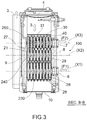
- 1 indicates in its entirety a plate heat exchanger which is the main object of the present invention.
- the heat exchanger 1 comprises a set of heat exchanging elements, called plates 2, having a substantially rectangular shape.
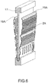
- Each plate 2 is made by using a single sheet metal starting from a single folded sheet 2A ( figures 4 and 5 ).
- the fluid to be heated passes within each plate 2; the combustion products 3 (fumes), coming from a burner 4 present in a combustion chamber 4A, flow outside, and in particular in a plurality of gaps 40 formed between a plate 2 and the other.
- the combustion products 3 coming from a burner 4 present in a combustion chamber 4A, flow outside, and in particular in a plurality of gaps 40 formed between a plate 2 and the other.
- Heat exchanger 1 is preferably intended to be used in a gas condensing boiler 100 ( figures 2 , 3 ), where the heated fluid is water, the fuel is natural gas and the combustion products 3 are cooled to the condensation point of water vapour and moisture contained in them.
- heat exchanger 1 The typical (but not exclusive) arrangement of heat exchanger 1 is the one shown in figures 2 and 3 .
- burner 4 is placed at the top of boiler 100 and above heat exchanger 1. Flame of the burner 4 is facing downwards and, on a first stretch, the combustion products 3 flow vertically downwards in order to pass through gaps 40 that are located between plates 2 of heat exchanger 1.
- Combustion products 3 are collected in the lower part, below heat exchanger 1, to be finally discharged through a vertical exhaust duct 5.
- the lower front part of the heat exchanger comprises a fitting 6 for its connection to the system return flow ( figure 3 ; arrow (F1)), while the upper front part comprises a fitting 7 for its connection to the system supply flow ( figure 3 ; arrow (F2)).
- Plates 2 are arranged inside a container comprising, for example, a pair of containment plates 8, 9 made of aluminium in contact with the outer walls of the two front and back plates 2 of heat exchanger 1, and a casing 10 for the collection of combustion products.
- casing 10 comprises an exhaust duct 11 for the produced condensate ( figure 2 ).
- plate 9 is provided with a hole 9A connecting it to the exhaust duct 5 for combustion products 3.
- the other plate 8 can be usefully provided with an access hole 13 to the casing 10, so that an operator can carry out its periodic maintenance and cleaning from the corrosion products which in time are inevitably produced and collected in its bottom.
- the heat exchanger 1 essentially comprises a plurality of heat exchange plates 2.
- Each plate 2 substantially consists of a shell of sheet metal having a suitable thickness, made (preferably but not necessarily) of stainless steel, inside which the water of the boiler circulates, while the combustion products 3 ( figures 2 , 3 ) pass outside, in the gap 40 formed by the adjacent walls of two plates 2.
- Each plate 2 is manufactured starting from a sheet metal 2A ( figure 4 ) which is formed, then plastically deformed by drawing and sheared, thus obtaining two central zones 18A, 18B, lowered with respect to a horizontal reference plane 19 on which the outer edge is located.
- inner side strips 20 are provided on the same horizontal reference plane 19 ( figure 4 ) .
- through holes 14 are then formed in the amount and positions necessary for the operation shown below.
- the shaped and perforated metal sheet 2A is subjected to a bending operation along the middle line (MZ) ( figure 4 ), as shown in figure 6 .
- the folding of metal sheet 2A along the middle line (MZ) is achieved by using a special folding tool 17 ( figure 6 ).
- the metal sheet 2A is folded with a suitable bending radius until obtaining an almost complete closure that allows, however, the bending tool 17 to be removed by extraction.
- the metal sheet 2A folded along the middle line (MZ) is then completely closed by crushing the rectangular outer edge 19A so as to bring into contact the flaps of metal sheet of the three sides which are drawn near.
- the thus obtained element is finally welded on the three sides 15 and in the inner areas lying on the same plane of the peripheral edge during the previous drawing step; all according to techniques of autogenous welding or brazing which are widely known in the art.
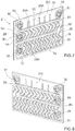
- plates 2 are assembled by interposing toroidal gaskets 21 ( figure 3 ) in correspondence to through holes 14 for the passage of water.
- Plates 2 are held in position by using tie rods 22 and containment plates 8, 9 of all plates 2 of heat exchanger 1 ( figure 1 ).
- plates 2 are assembled and kept in their position by autogenous welding or brazing on circular rings 32 surrounding the through holes 14 for the passage of water ( figure 7 ).
- each exchange element three horizontal and mutually parallel channels 23, 24, 25 are formed in which the water flows in a horizontal direction, perpendicular to the vertical direction of the fumes (downwards) ( figures 2 , 3 ).
- the lower channel 23 and the intermediate channel 24 are hydraulically connected, on the right side of the plate 2, by means of a passage 26.
- the water can thus rise from a first lower level (I), where lower channels 23 are arranged, to a second intermediate level (II) ( figure 7 ), where intermediate channels 24 are arranged.
- the intermediate channel 24 arranged at the second level (II) and the upper channel 25 arranged at a third level (III) are not in hydraulic communication.
- the intermediate channel 24 and the upper channel 25 are, on the other hand, in hydraulic communication through a passage 27 that allows the rise of heated water from the second (II) to the third (III) level ( figure 9 ).
- the passage 27 is arranged on the left side of the plate 2*.
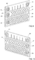
- each plate 2 in correspondence to channels 23 of the lower layer, comprises a first opening 28 formed by overlapping two holes 14 which, as previously stated, have been made on sheet 2A ( figure 4 ).
- the two holes 14 for obtaining the first opening 28 are superimposed by bending metal sheet 2A, as seen with a reference to figures 4 and 5 .
- the first openings 28, the plurality of plates 2, 2* and the fitting 6 form together a first horizontal duct 230 having an axis (X1) substantially perpendicular to the plurality of lower channels 23.
- the water cannot leave the plates 2, 2* through the first openings 28 to flow in the gaps 40 (where, on the contrary, the combustion gas must flow) due to the presence, between a plate 2, 2* and the other and in correspondence to the first openings 28, of the aforementioned toroidal gaskets 21.
- a plurality of second openings 29 of the plurality of plates 2, 2* form a second horizontal duct 240 having an axis (X2) substantially perpendicular to the plurality of intermediate channels 24 ( figure 3 ).
- a third opening 30 and a fourth opening 31 are formed to provide a water circulation in series or in parallel in the set of plates 2, 2* forming the heat exchanger 1 according to what described below.
- first level (I) and the second level (II) are provided only with a respective opening 28, 28, the third level (III) is provided with two openings 30, 31, precisely because only the third level (III) will possibly have to be provided with connections in series between the various plates 2, 2*.
- the number of openings 28, 29, 30, 31 must be equal to that of the levels (I), (II), (III) plus one. In the present case, therefore, there are four openings for three levels.
- Third openings 30 and fitting 7 (all aligned along an axis (X3)) form together a third horizontal duct 250 arranged at the third level (III); such third horizontal duct 250 being perpendicular to all the upper channels 25.
- the fourth openings 31, which are also aligned along an axis (X4), are used to achieve the hydraulic connections in series between the plates 2, 2* at the third level (III).
- the four axes (X1), (X2), (X3) (X4) are parallel to each other ( figure 11 ).
- sealing gaskets 21 having a toroidal shape are used to prevent the leakage of water to the gaps 40.
- openings 28 arranged in the lower left part of plates 2 form the aforementioned first horizontal duct 230 which acts as a collector of the system return water (arrow (F1)).
- a pipe (not shown in the figures) provided with calibrated holes in correspondence to the single elements can be used to obtain an even distribution of the water inside the plates 2, 2*.
- the water proceeds horizontally following a direction opposite to the one of the first level (I) until it reaches the second horizontal duct 240 and flows transversely to plates 2, 2*.
- the third level (III) is the one directly exposed to the flame of the burner 4.
- the channels 25 formed in the plates 2, 2* have perforated walls at their ends, which are open or closed in order to guarantee that the water flows through the horizontal channel 25 of the third level (III) of each plate 2 in series or in parallel with the channel 25 of the adjacent plate 2 according to needs which will be later described.
- channels 23, 24, 25 outward facing imprints 23A, 24A, 25A have been obtained, by means of drawing, whose shape and depth are such that:
- both the flaps 23A and the flaps 24A are significantly less in number than flaps 25A and have a more complex shape because, while in the areas closer to the flame of burner 4 (third level (III); figures 2 , 3 ) the water must not boil, the heat exchange must be promoted as much as possible in the other two layers (I) and (II), where the arriving fumes are much colder.
- channels 25 of the third level (III) have a smaller drawing depth than channels 23 of the first level (I) and channels 24 of the second level (II), thus increasing the cross section of the fumes passage between adjacent plates and, at the same time, increasing the water speed inside channels 25, always in order to avoid the risk of boiling water.
- channels 25 of the third level (III) of each pair of plates 2, 2* are in series with respect to the preceding or following pairs of plates 2; 2* ( figure 13 ).
- the water leaves heat exchanger 1 through opening 30 formed in the front wall of front plate 2 to be sent to the system delivery duct through fitting 7.
- opening 30 connecting the heat exchanger 1 to the system delivery duct can be arranged at the left end (as in the example of the figure), or at right end of said front plate 2.
- a plurality of diaphragms 50 for closing for example by welding (as in the example of figures 11 , 12 ), or by interposing additional toroidal gaskets, the openings 28, 29, 30, 30 formed on the plates 2, 2* for creating the hydraulic circuits must be available.
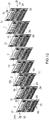
- FIG. 1 refers to a 24.5 kW heat exchanger 1 formed by eight elements with seven gaps crossed by the fumes (fumes channels).
- the loss of thermal load in the whole heat exchanger and of water speed in the single channels of the third level obtained in this embodiment are optimal for the application in gas boilers with this power.
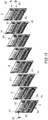
- Figures 14 , 15 , 16 show a second heat exchanger, once again formed by eight plates, but having in the third level (III) a sequence of three channels in parallel followed by further three channels in parallel followed by further two channels in parallel.
- this heat exchanger has a load loss which is 20% lower than the preceding one, and a water speed inside the three parallel channels of the third level lower than 30%.
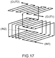
- the flow diagram in figure 17 shows a further possible combination of the same number of plates intended to exchange the same power with a much smaller loss of load. While in the flow diagrams of figures 13 and 16 there is only one water inlet (IN) and one water outlet (OUT), the flow diagram of figure 17 shows a case with two water inlets (IN1), (IN2) and two water outlets (OUT1), (OUT2). In this case the eight plates have been divided into two groups, each consisting of four adjacent plates having the ducts of the third level (III) connected in series.
- Each group has its own connection to the system return flow and to the system supply flow, whereas the burner remains only one for the whole heat exchanger.
- this heat exchanger has a load loss lower than 50% if compared to the starting embodiment, while maintaining the water speed in the third layer (III) at the same value.
- some of the holes of the plates can be closed from the beginning; i.e. the sheet metals used to build some of the plates are not cut in the areas where instead the through holes, subsequently closed by the diaphragms, should be found.
- the sheet metals used to build some of the plates are not cut in the areas where instead the through holes, subsequently closed by the diaphragms, should be found.
- the manufacturer has to choose the best solution to have the lowest possible number of types of plates, though avoiding, as far as possible, to open some through holes on the plates which must then be closed again by diaphragms.
Landscapes
- Engineering & Computer Science (AREA)
- Physics & Mathematics (AREA)
- Thermal Sciences (AREA)
- Mechanical Engineering (AREA)
- General Engineering & Computer Science (AREA)
- Chemical & Material Sciences (AREA)
- Combustion & Propulsion (AREA)
- Heat-Exchange Devices With Radiators And Conduit Assemblies (AREA)
Priority Applications (1)
| Application Number | Priority Date | Filing Date | Title |
|---|---|---|---|
| PL14828286T PL3071897T3 (pl) | 2013-11-20 | 2014-11-20 | Płytowy wymiennik ciepła, w szczególności do kotłów kondensacyjnych |
Applications Claiming Priority (2)
| Application Number | Priority Date | Filing Date | Title |
|---|---|---|---|
| IT000632A ITBO20130632A1 (it) | 2013-11-20 | 2013-11-20 | Scambiatore di calore a piastre, in particolare per caldaie a condensazione |
| PCT/IB2014/066208 WO2015075672A1 (en) | 2013-11-20 | 2014-11-20 | Plate heat exchanger, in particular for condensing boilers |
Publications (2)
| Publication Number | Publication Date |
|---|---|
| EP3071897A1 EP3071897A1 (en) | 2016-09-28 |
| EP3071897B1 true EP3071897B1 (en) | 2019-09-11 |
Family
ID=49725194
Family Applications (1)
| Application Number | Title | Priority Date | Filing Date |
|---|---|---|---|
| EP14828286.6A Active EP3071897B1 (en) | 2013-11-20 | 2014-11-20 | Plate heat exchanger, in particular for condensing boilers |
Country Status (7)
| Country | Link |
|---|---|
| US (1) | US10458679B2 (pl) |
| EP (1) | EP3071897B1 (pl) |
| KR (1) | KR102247109B1 (pl) |
| ES (1) | ES2759067T3 (pl) |
| IT (1) | ITBO20130632A1 (pl) |
| PL (1) | PL3071897T3 (pl) |
| WO (1) | WO2015075672A1 (pl) |
Families Citing this family (10)
| Publication number | Priority date | Publication date | Assignee | Title |
|---|---|---|---|---|
| DE102015101048B3 (de) * | 2015-01-26 | 2016-06-09 | Viessmann Werke Gmbh & Co Kg | Heizkessel |
| KR101717096B1 (ko) * | 2015-07-23 | 2017-03-27 | 주식회사 경동나비엔 | 열교환기 |
| KR101717095B1 (ko) * | 2015-07-23 | 2017-03-27 | 주식회사 경동나비엔 | 열교환기 |
| KR101717093B1 (ko) * | 2015-07-23 | 2017-03-27 | 주식회사 경동나비엔 | 열교환기 |
| KR101717092B1 (ko) * | 2015-08-28 | 2017-03-27 | 주식회사 경동나비엔 | 열교환기 |
| KR101717097B1 (ko) * | 2015-08-28 | 2017-03-16 | 주식회사 경동나비엔 | 열교환기 |
| CN116772624B (zh) | 2018-06-07 | 2026-03-03 | 阿法拉伐股份有限公司 | 板式热交换器、热交换板和处理诸如海水的供给物的方法 |
| CN110657692B (zh) * | 2018-06-29 | 2020-12-08 | 浙江三花汽车零部件有限公司 | 一种换热器 |
| CN112648868B (zh) * | 2020-12-01 | 2023-05-30 | 合肥通用机械研究院有限公司 | 一种全尺度隐式扩散焊板式换热器 |
| CN117268146B (zh) * | 2023-11-15 | 2024-01-26 | 中国核动力研究设计院 | 一种扩散焊换热器及其设计方法 |
Family Cites Families (23)
| Publication number | Priority date | Publication date | Assignee | Title |
|---|---|---|---|---|
| US3334399A (en) * | 1962-12-31 | 1967-08-08 | Stewart Warner Corp | Brazed laminated construction and method of fabrication thereof |
| BE764949A (fr) | 1970-04-04 | 1971-08-16 | Riello Pilade | Element en tole pour chaudiere a gaz |
| DE3020557C2 (de) * | 1980-05-30 | 1984-04-26 | Daimler-Benz Ag, 7000 Stuttgart | Kreuzstrom-Plattenwärmetauscher als Ölkühler für Brennkraftmaschinen, insbesondere von Kraftfahrzeugen |
| US5470431A (en) * | 1990-08-20 | 1995-11-28 | Showa Aluminum Corp. | Stack type evaporator |
| US5109806A (en) * | 1990-10-15 | 1992-05-05 | The Marley Company | Premix boiler construction |
| US5855240A (en) * | 1998-06-03 | 1999-01-05 | Ford Motor Company | Automotive heat exchanger |
| DE10043283A1 (de) | 2000-09-02 | 2002-03-14 | Bosch Gmbh Robert | Wärmetauscher für einen Heizkessel, insbesondere für ein Brennwertgerät |
| US6745827B2 (en) * | 2001-09-29 | 2004-06-08 | Halla Climate Control Corporation | Heat exchanger |
| FR2834336B1 (fr) * | 2001-12-28 | 2006-12-01 | Valeo Thermique Moteur Sa | Element de circuit pour echangeur de chaleur, notamment de vehicule automobile et echangeur de chaleur ainsi obtenu |
| ITMO20020163A1 (it) | 2002-06-13 | 2003-12-15 | Worgas Bruciatori Srl | Scambiatore di calore |
| US6948559B2 (en) * | 2003-02-19 | 2005-09-27 | Modine Manufacturing Company | Three-fluid evaporative heat exchanger |
| DE10328746A1 (de) * | 2003-06-25 | 2005-01-13 | Behr Gmbh & Co. Kg | Vorrichtung zum mehrstufigen Wärmeaustausch und Verfahren zur Herstellung einer derartigen Vorrichtung |
| FR2856747B1 (fr) * | 2003-06-25 | 2005-09-23 | Valeo Thermique Moteur Sa | Module de refroidissement de l'air de suralimentation et des gaz d'echappement recircules d'un moteur a combustion interne de vehicule automobile. |
| US7063047B2 (en) * | 2003-09-16 | 2006-06-20 | Modine Manufacturing Company | Fuel vaporizer for a reformer type fuel cell system |
| DE102005033050A1 (de) | 2004-08-06 | 2006-03-16 | Vaillant Gmbh | Wärmezelle für ein Heizgerät |
| ITBO20070143A1 (it) | 2007-03-02 | 2008-09-03 | Gas Point S R L | Caldaia a condensazione |
| FR2958389B1 (fr) * | 2010-03-31 | 2012-07-13 | Valeo Systemes Thermiques | Echangeur de chaleur et lame pour l'echangeur |
| US20120088200A1 (en) * | 2010-10-08 | 2012-04-12 | Carrier Corporation | Furnace heat exchanger |
| EP2643650A2 (en) * | 2010-11-22 | 2013-10-02 | Carrier Corporation | Multiple tube bank flattened tube finned heat exchanger |
| US9109840B2 (en) * | 2011-02-17 | 2015-08-18 | Delphi Technologies, Inc. | Unitary heat pump air conditioner having a heat exchanger with an integral accumulator |
| US20120222848A1 (en) * | 2011-03-01 | 2012-09-06 | Visteon Global Technologies, Inc. | Integrated counter cross flow condenser |
| BE1020068A5 (nl) * | 2011-07-11 | 2013-04-02 | Multicalor Ind Nv | Warmtewisselaar voor een hoog rendement hete lucht verwarmingstoestel en verwarmingstoestel daarmee uitgerust. |
| US20140158328A1 (en) * | 2012-07-05 | 2014-06-12 | Airec Ab | Plate for heat exchanger, heat exchanger and air cooler comprising a heat exchanger |
-
2013
- 2013-11-20 IT IT000632A patent/ITBO20130632A1/it unknown
-
2014
- 2014-11-20 PL PL14828286T patent/PL3071897T3/pl unknown
- 2014-11-20 US US15/038,335 patent/US10458679B2/en active Active
- 2014-11-20 KR KR1020167016385A patent/KR102247109B1/ko active Active
- 2014-11-20 ES ES14828286T patent/ES2759067T3/es active Active
- 2014-11-20 EP EP14828286.6A patent/EP3071897B1/en active Active
- 2014-11-20 WO PCT/IB2014/066208 patent/WO2015075672A1/en not_active Ceased
Non-Patent Citations (1)
| Title |
|---|
| None * |
Also Published As
| Publication number | Publication date |
|---|---|
| ITBO20130632A1 (it) | 2015-05-21 |
| EP3071897A1 (en) | 2016-09-28 |
| US20160298874A1 (en) | 2016-10-13 |
| ES2759067T3 (es) | 2020-05-07 |
| KR102247109B1 (ko) | 2021-05-03 |
| PL3071897T3 (pl) | 2020-03-31 |
| US10458679B2 (en) | 2019-10-29 |
| WO2015075672A1 (en) | 2015-05-28 |
| KR20160113101A (ko) | 2016-09-28 |
Similar Documents
| Publication | Publication Date | Title |
|---|---|---|
| EP3071897B1 (en) | Plate heat exchanger, in particular for condensing boilers | |
| EP2160560B1 (en) | Heat exchanger for a boiler | |
| EP2176616B1 (en) | Heat exchanger | |
| EP2140208B1 (en) | Heat exchanger | |
| RU2535187C1 (ru) | Пластинчатый теплообменник с шахматным расположением каналов | |
| EP2491326B1 (en) | Improvements to a heat-exchanger for a boiler | |
| EP2676094B1 (en) | Method of producing a heat exchanger and a heat exchanger | |
| EP3017261B1 (en) | Asymmetrical exchanger with ancillary channels for connecting turns | |
| RU2348882C1 (ru) | Теплообменник астановского радиально-спирального типа (варианты) | |
| JP2010121925A (ja) | 熱交換器 | |
| CN213455064U (zh) | 一种均热冷板换热器 | |
| EP2122287A1 (en) | Plate heat exchanger | |
| US10697708B2 (en) | Heat exchangers | |
| CN105258536A (zh) | 一种新型全焊接板壳式换热器 | |
| JP2010117102A (ja) | 熱交換器 | |
| CN210154381U (zh) | 高效率换热器 | |
| RU2222752C2 (ru) | Установка нагрева воды для отопления и/или горячего водоснабжения, охлаждаемый конденсатосборник установки, теплообменник "жидкость-жидкость" установки | |
| JPH0539326Y2 (pl) | ||
| KR20240103773A (ko) | 열교환기 | |
| EP3426986B1 (en) | Sectional heat exchanger for use in a heat cell | |
| RU2640263C1 (ru) | Теплообменник | |
| KR20250125939A (ko) | 열 교환기 | |
| CN106323070A (zh) | 半焊接式换热板 | |
| RS67070B1 (sr) | Izmenjivač toplote sa zavarenim unutrašnjim izmenjivačkim pločama | |
| PL70454Y1 (pl) | Płytowy wymiennik ciepła kotła grzewczego |
Legal Events
| Date | Code | Title | Description |
|---|---|---|---|
| PUAI | Public reference made under article 153(3) epc to a published international application that has entered the european phase |
Free format text: ORIGINAL CODE: 0009012 |
|
| 17P | Request for examination filed |
Effective date: 20160520 |
|
| AK | Designated contracting states |
Kind code of ref document: A1 Designated state(s): AL AT BE BG CH CY CZ DE DK EE ES FI FR GB GR HR HU IE IS IT LI LT LU LV MC MK MT NL NO PL PT RO RS SE SI SK SM TR |
|
| AX | Request for extension of the european patent |
Extension state: BA ME |
|
| DAX | Request for extension of the european patent (deleted) | ||
| GRAP | Despatch of communication of intention to grant a patent |
Free format text: ORIGINAL CODE: EPIDOSNIGR1 |
|
| STAA | Information on the status of an ep patent application or granted ep patent |
Free format text: STATUS: GRANT OF PATENT IS INTENDED |
|
| INTG | Intention to grant announced |
Effective date: 20190329 |
|
| GRAS | Grant fee paid |
Free format text: ORIGINAL CODE: EPIDOSNIGR3 |
|
| GRAA | (expected) grant |
Free format text: ORIGINAL CODE: 0009210 |
|
| STAA | Information on the status of an ep patent application or granted ep patent |
Free format text: STATUS: THE PATENT HAS BEEN GRANTED |
|
| AK | Designated contracting states |
Kind code of ref document: B1 Designated state(s): AL AT BE BG CH CY CZ DE DK EE ES FI FR GB GR HR HU IE IS IT LI LT LU LV MC MK MT NL NO PL PT RO RS SE SI SK SM TR |
|
| REG | Reference to a national code |
Ref country code: GB Ref legal event code: FG4D |
|
| REG | Reference to a national code |
Ref country code: CH Ref legal event code: EP |
|
| REG | Reference to a national code |
Ref country code: AT Ref legal event code: REF Ref document number: 1178936 Country of ref document: AT Kind code of ref document: T Effective date: 20190915 |
|
| REG | Reference to a national code |
Ref country code: DE Ref legal event code: R096 Ref document number: 602014053576 Country of ref document: DE |
|
| REG | Reference to a national code |
Ref country code: IE Ref legal event code: FG4D |
|
| REG | Reference to a national code |
Ref country code: NL Ref legal event code: FP |
|
| REG | Reference to a national code |
Ref country code: LT Ref legal event code: MG4D |
|
| PG25 | Lapsed in a contracting state [announced via postgrant information from national office to epo] |
Ref country code: FI Free format text: LAPSE BECAUSE OF FAILURE TO SUBMIT A TRANSLATION OF THE DESCRIPTION OR TO PAY THE FEE WITHIN THE PRESCRIBED TIME-LIMIT Effective date: 20190911 Ref country code: LT Free format text: LAPSE BECAUSE OF FAILURE TO SUBMIT A TRANSLATION OF THE DESCRIPTION OR TO PAY THE FEE WITHIN THE PRESCRIBED TIME-LIMIT Effective date: 20190911 Ref country code: BG Free format text: LAPSE BECAUSE OF FAILURE TO SUBMIT A TRANSLATION OF THE DESCRIPTION OR TO PAY THE FEE WITHIN THE PRESCRIBED TIME-LIMIT Effective date: 20191211 Ref country code: NO Free format text: LAPSE BECAUSE OF FAILURE TO SUBMIT A TRANSLATION OF THE DESCRIPTION OR TO PAY THE FEE WITHIN THE PRESCRIBED TIME-LIMIT Effective date: 20191211 Ref country code: HR Free format text: LAPSE BECAUSE OF FAILURE TO SUBMIT A TRANSLATION OF THE DESCRIPTION OR TO PAY THE FEE WITHIN THE PRESCRIBED TIME-LIMIT Effective date: 20190911 Ref country code: SE Free format text: LAPSE BECAUSE OF FAILURE TO SUBMIT A TRANSLATION OF THE DESCRIPTION OR TO PAY THE FEE WITHIN THE PRESCRIBED TIME-LIMIT Effective date: 20190911 |
|
| PG25 | Lapsed in a contracting state [announced via postgrant information from national office to epo] |
Ref country code: RS Free format text: LAPSE BECAUSE OF FAILURE TO SUBMIT A TRANSLATION OF THE DESCRIPTION OR TO PAY THE FEE WITHIN THE PRESCRIBED TIME-LIMIT Effective date: 20190911 Ref country code: GR Free format text: LAPSE BECAUSE OF FAILURE TO SUBMIT A TRANSLATION OF THE DESCRIPTION OR TO PAY THE FEE WITHIN THE PRESCRIBED TIME-LIMIT Effective date: 20191212 Ref country code: AL Free format text: LAPSE BECAUSE OF FAILURE TO SUBMIT A TRANSLATION OF THE DESCRIPTION OR TO PAY THE FEE WITHIN THE PRESCRIBED TIME-LIMIT Effective date: 20190911 Ref country code: LV Free format text: LAPSE BECAUSE OF FAILURE TO SUBMIT A TRANSLATION OF THE DESCRIPTION OR TO PAY THE FEE WITHIN THE PRESCRIBED TIME-LIMIT Effective date: 20190911 |
|
| REG | Reference to a national code |
Ref country code: AT Ref legal event code: MK05 Ref document number: 1178936 Country of ref document: AT Kind code of ref document: T Effective date: 20190911 |
|
| PG25 | Lapsed in a contracting state [announced via postgrant information from national office to epo] |
Ref country code: EE Free format text: LAPSE BECAUSE OF FAILURE TO SUBMIT A TRANSLATION OF THE DESCRIPTION OR TO PAY THE FEE WITHIN THE PRESCRIBED TIME-LIMIT Effective date: 20190911 Ref country code: AT Free format text: LAPSE BECAUSE OF FAILURE TO SUBMIT A TRANSLATION OF THE DESCRIPTION OR TO PAY THE FEE WITHIN THE PRESCRIBED TIME-LIMIT Effective date: 20190911 Ref country code: PT Free format text: LAPSE BECAUSE OF FAILURE TO SUBMIT A TRANSLATION OF THE DESCRIPTION OR TO PAY THE FEE WITHIN THE PRESCRIBED TIME-LIMIT Effective date: 20200113 Ref country code: RO Free format text: LAPSE BECAUSE OF FAILURE TO SUBMIT A TRANSLATION OF THE DESCRIPTION OR TO PAY THE FEE WITHIN THE PRESCRIBED TIME-LIMIT Effective date: 20190911 |
|
| REG | Reference to a national code |
Ref country code: ES Ref legal event code: FG2A Ref document number: 2759067 Country of ref document: ES Kind code of ref document: T3 Effective date: 20200507 |
|
| PG25 | Lapsed in a contracting state [announced via postgrant information from national office to epo] |
Ref country code: SK Free format text: LAPSE BECAUSE OF FAILURE TO SUBMIT A TRANSLATION OF THE DESCRIPTION OR TO PAY THE FEE WITHIN THE PRESCRIBED TIME-LIMIT Effective date: 20190911 Ref country code: CZ Free format text: LAPSE BECAUSE OF FAILURE TO SUBMIT A TRANSLATION OF THE DESCRIPTION OR TO PAY THE FEE WITHIN THE PRESCRIBED TIME-LIMIT Effective date: 20190911 Ref country code: IS Free format text: LAPSE BECAUSE OF FAILURE TO SUBMIT A TRANSLATION OF THE DESCRIPTION OR TO PAY THE FEE WITHIN THE PRESCRIBED TIME-LIMIT Effective date: 20200224 Ref country code: SM Free format text: LAPSE BECAUSE OF FAILURE TO SUBMIT A TRANSLATION OF THE DESCRIPTION OR TO PAY THE FEE WITHIN THE PRESCRIBED TIME-LIMIT Effective date: 20190911 |
|
| REG | Reference to a national code |
Ref country code: DE Ref legal event code: R097 Ref document number: 602014053576 Country of ref document: DE |
|
| REG | Reference to a national code |
Ref country code: CH Ref legal event code: PL |
|
| PLBE | No opposition filed within time limit |
Free format text: ORIGINAL CODE: 0009261 |
|
| STAA | Information on the status of an ep patent application or granted ep patent |
Free format text: STATUS: NO OPPOSITION FILED WITHIN TIME LIMIT |
|
| PG2D | Information on lapse in contracting state deleted |
Ref country code: IS |
|
| PG25 | Lapsed in a contracting state [announced via postgrant information from national office to epo] |
Ref country code: LI Free format text: LAPSE BECAUSE OF NON-PAYMENT OF DUE FEES Effective date: 20191130 Ref country code: CH Free format text: LAPSE BECAUSE OF NON-PAYMENT OF DUE FEES Effective date: 20191130 Ref country code: DK Free format text: LAPSE BECAUSE OF FAILURE TO SUBMIT A TRANSLATION OF THE DESCRIPTION OR TO PAY THE FEE WITHIN THE PRESCRIBED TIME-LIMIT Effective date: 20190911 Ref country code: LU Free format text: LAPSE BECAUSE OF NON-PAYMENT OF DUE FEES Effective date: 20191120 Ref country code: MC Free format text: LAPSE BECAUSE OF FAILURE TO SUBMIT A TRANSLATION OF THE DESCRIPTION OR TO PAY THE FEE WITHIN THE PRESCRIBED TIME-LIMIT Effective date: 20190911 Ref country code: IS Free format text: LAPSE BECAUSE OF FAILURE TO SUBMIT A TRANSLATION OF THE DESCRIPTION OR TO PAY THE FEE WITHIN THE PRESCRIBED TIME-LIMIT Effective date: 20200112 |
|
| 26N | No opposition filed |
Effective date: 20200615 |
|
| REG | Reference to a national code |
Ref country code: BE Ref legal event code: MM Effective date: 20191130 |
|
| PG25 | Lapsed in a contracting state [announced via postgrant information from national office to epo] |
Ref country code: SI Free format text: LAPSE BECAUSE OF FAILURE TO SUBMIT A TRANSLATION OF THE DESCRIPTION OR TO PAY THE FEE WITHIN THE PRESCRIBED TIME-LIMIT Effective date: 20190911 |
|
| PG25 | Lapsed in a contracting state [announced via postgrant information from national office to epo] |
Ref country code: IE Free format text: LAPSE BECAUSE OF NON-PAYMENT OF DUE FEES Effective date: 20191120 |
|
| PG25 | Lapsed in a contracting state [announced via postgrant information from national office to epo] |
Ref country code: BE Free format text: LAPSE BECAUSE OF NON-PAYMENT OF DUE FEES Effective date: 20191130 |
|
| PG25 | Lapsed in a contracting state [announced via postgrant information from national office to epo] |
Ref country code: CY Free format text: LAPSE BECAUSE OF FAILURE TO SUBMIT A TRANSLATION OF THE DESCRIPTION OR TO PAY THE FEE WITHIN THE PRESCRIBED TIME-LIMIT Effective date: 20190911 |
|
| PG25 | Lapsed in a contracting state [announced via postgrant information from national office to epo] |
Ref country code: MT Free format text: LAPSE BECAUSE OF FAILURE TO SUBMIT A TRANSLATION OF THE DESCRIPTION OR TO PAY THE FEE WITHIN THE PRESCRIBED TIME-LIMIT Effective date: 20190911 Ref country code: HU Free format text: LAPSE BECAUSE OF FAILURE TO SUBMIT A TRANSLATION OF THE DESCRIPTION OR TO PAY THE FEE WITHIN THE PRESCRIBED TIME-LIMIT; INVALID AB INITIO Effective date: 20141120 |
|
| PG25 | Lapsed in a contracting state [announced via postgrant information from national office to epo] |
Ref country code: MK Free format text: LAPSE BECAUSE OF FAILURE TO SUBMIT A TRANSLATION OF THE DESCRIPTION OR TO PAY THE FEE WITHIN THE PRESCRIBED TIME-LIMIT Effective date: 20190911 |
|
| P01 | Opt-out of the competence of the unified patent court (upc) registered |
Effective date: 20230508 |
|
| PGFP | Annual fee paid to national office [announced via postgrant information from national office to epo] |
Ref country code: NL Payment date: 20251124 Year of fee payment: 12 |
|
| PGFP | Annual fee paid to national office [announced via postgrant information from national office to epo] |
Ref country code: DE Payment date: 20251126 Year of fee payment: 12 |
|
| PGFP | Annual fee paid to national office [announced via postgrant information from national office to epo] |
Ref country code: GB Payment date: 20251125 Year of fee payment: 12 |
|
| PGFP | Annual fee paid to national office [announced via postgrant information from national office to epo] |
Ref country code: IT Payment date: 20251104 Year of fee payment: 12 |
|
| PGFP | Annual fee paid to national office [announced via postgrant information from national office to epo] |
Ref country code: FR Payment date: 20251124 Year of fee payment: 12 |
|
| PGFP | Annual fee paid to national office [announced via postgrant information from national office to epo] |
Ref country code: TR Payment date: 20251031 Year of fee payment: 12 |
|
| PGFP | Annual fee paid to national office [announced via postgrant information from national office to epo] |
Ref country code: PL Payment date: 20251023 Year of fee payment: 12 |
|
| PGFP | Annual fee paid to national office [announced via postgrant information from national office to epo] |
Ref country code: ES Payment date: 20251209 Year of fee payment: 12 |