EP3071790B1 - Wired pipe and method of manufacturing wired pipe - Google Patents
Wired pipe and method of manufacturing wired pipe Download PDFInfo
- Publication number
- EP3071790B1 EP3071790B1 EP14863193.0A EP14863193A EP3071790B1 EP 3071790 B1 EP3071790 B1 EP 3071790B1 EP 14863193 A EP14863193 A EP 14863193A EP 3071790 B1 EP3071790 B1 EP 3071790B1
- Authority
- EP
- European Patent Office
- Prior art keywords
- pipe body
- channel
- pipe
- transmission line
- wall
- Prior art date
- Legal status (The legal status is an assumption and is not a legal conclusion. Google has not performed a legal analysis and makes no representation as to the accuracy of the status listed.)
- Active
Links
Images


Classifications
-
- E—FIXED CONSTRUCTIONS
- E21—EARTH OR ROCK DRILLING; MINING
- E21B—EARTH OR ROCK DRILLING; OBTAINING OIL, GAS, WATER, SOLUBLE OR MELTABLE MATERIALS OR A SLURRY OF MINERALS FROM WELLS
- E21B17/00—Drilling rods or pipes; Flexible drill strings; Kellies; Drill collars; Sucker rods; Cables; Casings; Tubings
- E21B17/003—Drilling rods or pipes; Flexible drill strings; Kellies; Drill collars; Sucker rods; Cables; Casings; Tubings with electrically conducting or insulating means
-
- B—PERFORMING OPERATIONS; TRANSPORTING
- B21—MECHANICAL METAL-WORKING WITHOUT ESSENTIALLY REMOVING MATERIAL; PUNCHING METAL
- B21C—MANUFACTURE OF METAL SHEETS, WIRE, RODS, TUBES, PROFILES OR LIKE SEMI-MANUFACTURED PRODUCTS OTHERWISE THAN BY ROLLING; AUXILIARY OPERATIONS USED IN CONNECTION WITH METAL-WORKING WITHOUT ESSENTIALLY REMOVING MATERIAL
- B21C23/00—Extruding metal; Impact extrusion
- B21C23/02—Making uncoated products
- B21C23/04—Making uncoated products by direct extrusion
- B21C23/08—Making wire, rods or tubes
- B21C23/085—Making tubes
-
- B—PERFORMING OPERATIONS; TRANSPORTING
- B21—MECHANICAL METAL-WORKING WITHOUT ESSENTIALLY REMOVING MATERIAL; PUNCHING METAL
- B21C—MANUFACTURE OF METAL SHEETS, WIRE, RODS, TUBES, PROFILES OR LIKE SEMI-MANUFACTURED PRODUCTS OTHERWISE THAN BY ROLLING; AUXILIARY OPERATIONS USED IN CONNECTION WITH METAL-WORKING WITHOUT ESSENTIALLY REMOVING MATERIAL
- B21C25/00—Profiling tools for metal extruding
- B21C25/04—Mandrels
-
- B—PERFORMING OPERATIONS; TRANSPORTING
- B21—MECHANICAL METAL-WORKING WITHOUT ESSENTIALLY REMOVING MATERIAL; PUNCHING METAL
- B21C—MANUFACTURE OF METAL SHEETS, WIRE, RODS, TUBES, PROFILES OR LIKE SEMI-MANUFACTURED PRODUCTS OTHERWISE THAN BY ROLLING; AUXILIARY OPERATIONS USED IN CONNECTION WITH METAL-WORKING WITHOUT ESSENTIALLY REMOVING MATERIAL
- B21C37/00—Manufacture of metal sheets, rods, wire, tubes, profiles or like semi-manufactured products, not otherwise provided for; Manufacture of tubes of special shape
- B21C37/06—Manufacture of metal sheets, rods, wire, tubes, profiles or like semi-manufactured products, not otherwise provided for; Manufacture of tubes of special shape of tubes or metal hoses; Combined procedures for making tubes, e.g. for making multi-wall tubes
- B21C37/15—Making tubes of special shape; Making tube fittings
- B21C37/151—Making tubes with multiple passages
-
- B—PERFORMING OPERATIONS; TRANSPORTING
- B29—WORKING OF PLASTICS; WORKING OF SUBSTANCES IN A PLASTIC STATE IN GENERAL
- B29C—SHAPING OR JOINING OF PLASTICS; SHAPING OF MATERIAL IN A PLASTIC STATE, NOT OTHERWISE PROVIDED FOR; AFTER-TREATMENT OF THE SHAPED PRODUCTS, e.g. REPAIRING
- B29C48/00—Extrusion moulding, i.e. expressing the moulding material through a die or nozzle which imparts the desired form; Apparatus therefor
- B29C48/03—Extrusion moulding, i.e. expressing the moulding material through a die or nozzle which imparts the desired form; Apparatus therefor characterised by the shape of the extruded material at extrusion
- B29C48/09—Articles with cross-sections having partially or fully enclosed cavities, e.g. pipes or channels
-
- B—PERFORMING OPERATIONS; TRANSPORTING
- B29—WORKING OF PLASTICS; WORKING OF SUBSTANCES IN A PLASTIC STATE IN GENERAL
- B29C—SHAPING OR JOINING OF PLASTICS; SHAPING OF MATERIAL IN A PLASTIC STATE, NOT OTHERWISE PROVIDED FOR; AFTER-TREATMENT OF THE SHAPED PRODUCTS, e.g. REPAIRING
- B29C48/00—Extrusion moulding, i.e. expressing the moulding material through a die or nozzle which imparts the desired form; Apparatus therefor
- B29C48/03—Extrusion moulding, i.e. expressing the moulding material through a die or nozzle which imparts the desired form; Apparatus therefor characterised by the shape of the extruded material at extrusion
- B29C48/131—Curved articles
-
- B—PERFORMING OPERATIONS; TRANSPORTING
- B29—WORKING OF PLASTICS; WORKING OF SUBSTANCES IN A PLASTIC STATE IN GENERAL
- B29C—SHAPING OR JOINING OF PLASTICS; SHAPING OF MATERIAL IN A PLASTIC STATE, NOT OTHERWISE PROVIDED FOR; AFTER-TREATMENT OF THE SHAPED PRODUCTS, e.g. REPAIRING
- B29C48/00—Extrusion moulding, i.e. expressing the moulding material through a die or nozzle which imparts the desired form; Apparatus therefor
- B29C48/25—Component parts, details or accessories; Auxiliary operations
- B29C48/285—Feeding the extrusion material to the extruder
- B29C48/288—Feeding the extrusion material to the extruder in solid form, e.g. powder or granules
- B29C48/2883—Feeding the extrusion material to the extruder in solid form, e.g. powder or granules of preformed parts, e.g. inserts, retaining their shape during the extrusion process
-
- B—PERFORMING OPERATIONS; TRANSPORTING
- B29—WORKING OF PLASTICS; WORKING OF SUBSTANCES IN A PLASTIC STATE IN GENERAL
- B29C—SHAPING OR JOINING OF PLASTICS; SHAPING OF MATERIAL IN A PLASTIC STATE, NOT OTHERWISE PROVIDED FOR; AFTER-TREATMENT OF THE SHAPED PRODUCTS, e.g. REPAIRING
- B29C48/00—Extrusion moulding, i.e. expressing the moulding material through a die or nozzle which imparts the desired form; Apparatus therefor
- B29C48/03—Extrusion moulding, i.e. expressing the moulding material through a die or nozzle which imparts the desired form; Apparatus therefor characterised by the shape of the extruded material at extrusion
- B29C48/09—Articles with cross-sections having partially or fully enclosed cavities, e.g. pipes or channels
- B29C48/11—Articles with cross-sections having partially or fully enclosed cavities, e.g. pipes or channels comprising two or more partially or fully enclosed cavities, e.g. honeycomb-shaped
-
- B—PERFORMING OPERATIONS; TRANSPORTING
- B29—WORKING OF PLASTICS; WORKING OF SUBSTANCES IN A PLASTIC STATE IN GENERAL
- B29C—SHAPING OR JOINING OF PLASTICS; SHAPING OF MATERIAL IN A PLASTIC STATE, NOT OTHERWISE PROVIDED FOR; AFTER-TREATMENT OF THE SHAPED PRODUCTS, e.g. REPAIRING
- B29C48/00—Extrusion moulding, i.e. expressing the moulding material through a die or nozzle which imparts the desired form; Apparatus therefor
- B29C48/25—Component parts, details or accessories; Auxiliary operations
- B29C48/30—Extrusion nozzles or dies
- B29C48/32—Extrusion nozzles or dies with annular openings, e.g. for forming tubular articles
-
- B—PERFORMING OPERATIONS; TRANSPORTING
- B29—WORKING OF PLASTICS; WORKING OF SUBSTANCES IN A PLASTIC STATE IN GENERAL
- B29L—INDEXING SCHEME ASSOCIATED WITH SUBCLASS B29C, RELATING TO PARTICULAR ARTICLES
- B29L2023/00—Tubular articles
- B29L2023/22—Tubes or pipes, i.e. rigid
-
- B—PERFORMING OPERATIONS; TRANSPORTING
- B29—WORKING OF PLASTICS; WORKING OF SUBSTANCES IN A PLASTIC STATE IN GENERAL
- B29L—INDEXING SCHEME ASSOCIATED WITH SUBCLASS B29C, RELATING TO PARTICULAR ARTICLES
- B29L2024/00—Articles with hollow walls
- B29L2024/006—Articles with hollow walls multi-channelled
Definitions
- a pipe or other conduit is lowered into the borehole in an earth formation during or after drilling operations.
- Such pipes are generally configured as multiple pipe segments to form a string, such as a drill string or production string.
- additional pipe segments are coupled to the string by various coupling mechanisms, such as threaded couplings.
- Various power and/or communication signals may be transmitted through the pipe segments via a "wired pipe” configuration.
- Such configurations include electrical, optical, or other conductors extending along the length of selected pipe segments.
- the conductors are operably connected between pipe segments by a coupling configuration such as a pin box connection.
- a coupling configuration such as a pin box connection.
- one or more conductors such as wires or cables are run along the inside diameter of a typically steel pipe segment.
- Various configurations have been proposed to fix, secure, and armor a wire relative to the interior diameter surface of the pipe segment.
- the conductors require protection from drilling or production fluid and other objects (such as cementing darts) that are pumped downhole or flowing through the pipe segments.
- Mechanisms to protect the conductors include small diameter protective steel tubings. Although such tubings serve to protect the conductors, they represent a potential obstacle to efficient fluid flow and components such as wireline measurement tools and cementing equipment that are disposed in the pipe segments.
- WO 99/19653 A1 describes a spoolable tube consisting of a composite material and suitable for use in the oil industry.
- the tube comprises an energy conductor, which is embedded in the wall of the tube and can be helically wound along the circumference of the tube.
- US 2011/017334 A1 describes a method of manufacturing a downhole conduit segment.
- the method includes extruding a material as a tubular shape to form a body of the conduit segment having an interior bore extending through a length of the segment, the body including an exterior surface and an interior surface defined by the interior bore, the material being an extrudable material sufficient to withstand conditions in a downhole environment; and extruding at least one passageway extending along the length of the body and disposed at least partially between the exterior surface and the interior surface, the at least one passageway having a shape configured to restrict lateral movement of a conductor disposed therein.
- a wired pipe includes a tubular pipe body having a wall, the wall including an inner surface, a flow channel formed by the inner surface, an outer surface, and at least one channel integrally formed within a thickness of the wall and between the inner and outer surfaces of the wall.
- the wired pipe further includes at least one transmission line disposed within the at least one channel, the at least one transmission line including at least one of an electrical conductor and an optical fiber.
- the tubular pipe body is made of a metal material, the at least one transmission line is extruded with the pipe body, and a melting temperature of at least an outer tube of the at least one transmission line is substantially equal to or greater than a melting temperature of the material of the pipe body.
- a method of forming a wired pipe includes extruding a tubular pipe body with a wall having an outer surface and an inner surface, the inner surface forming an interior flow channel; and, forming at least one channel through a thickness of the wall of the tubular pipe body, between the inner and outer surfaces.
- the method further includes inserting at least one transmission line within the at least one channel, the at least one transmission line including at least one of an electrical conductor and an optical fiber.
- the tubular pipe body is made of a metal material, the at least one transmission line is extruded with the pipe body, and a melting temperature of at least an outer tube of the at least one transmission line is substantially equal to or greater than a melting temperature of the material of the pipe body.
- Exemplary embodiments of a wired pipe 10 utilize a tubular pipe body, as shown in FIGS. 1-3 , with a signal communication channel for a transmission line, such as an insulated electrical conductor, wire, cable and/or optical fiber.
- the channel is formed during the manufacturing of the pipe body.
- FIG. 1 shows an exemplary embodiment of a pipe body 12 having a longitudinal axis 14 and one or more helical wire channels 16 formed within a wall 18 of the pipe body 12, from a first end 20 to a second end (not shown) of the pipe body 12. While the phrase "wire channel" is used, it should be understood that any line may be accommodated within the wire channel, such as, but not limited to, an insulated electrical conductor, wire, cable and/or optical fiber.
- the helical wire channel 16 is in the shape of a helix sharing the longitudinal axis 14 of the pipe body 12 and including one or more helical turns, depending on the length of the wired pipe 10.
- the helix angle of the helical wire channel 16 may be dependent upon the overall dimensions of the wired pipe 10.
- the wall 18 includes an outer surface 22 and an inner surface 24, and the helical wire channels 16 are formed between the outer and inner surfaces 22, 24 of the wall 18, within a thickness 26 of the wall 18. In the illustrated embodiment of FIG. 1 , the thickness 26 of the wall 18 is greater at the locations of the helical wire channel 16, such that an inner diameter of the pipe body 12 is not constant and is smaller at locations where the wire channels 16 are located and greater where the wire channels 16 are not located.
- An outer diameter of the pipe body 12 is substantially constant.
- a flow channel 28 is provided within an interior 30 of the pipe body 12, the flow channel 28 surrounded by the inner surface 24 of the wall 18. The wall 18 of the pipe body 12 isolates the wire channels 16 from the flow channel 28
- FIG. 2 shows another exemplary embodiment of a pipe body 112 having one or more helical wire channels 116 formed within a wall 118 of the pipe body 112.
- the wall 118 includes an outer surface 122 and an inner surface 124, and the helical wire channels 116 are formed between the outer and inner surfaces 122, 124 of the wall 118.
- a thickness 126 of the wall 118 is greater at locations of the helical wire channels 116.
- An outer diameter of the pipe body 112 is not constant and is smaller at locations where the wire channels 116 are not located and greater where the wire channels 116 are located.
- An inner diameter of the pipe body 112 is substantially constant.
- a flow channel 128 is provided within an interior 130 of the pipe body 112, the flow channel 128 surrounded by the inner surface 124 of the wall 118.
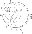
- FIG. 3 shows another exemplary embodiment of a pipe body 212 having one or more helical wire channels 216 formed within a wall 218 of the pipe body 212.
- the wall 218 includes an outer surface 222 and an inner surface 224, and the helical wire channels 216 are formed between the outer and inner surfaces 222, 224 of the wall 218.
- a thickness 226 is substantially uniform, such that an outer diameter of the pipe body 212 is substantially constant, and an inner diameter of the pipe body 212 is substantially constant.
- a flow channel 228 is provided within an interior 230 of the pipe body 212, the flow channel 228 surrounded by the inner surface 224 of the wall 218.
- a wall surrounding the wire channel as well as the wall of the pipe body must be of sufficient thickness to provide the required strength for torsion, tension, vibration and abrasion while not exceeding the requirements for weight and dimensions (relating to losses in a circulation system).
- weight and dimensions relating to losses in a circulation system.
- CDP conventional drill pipe
- the dimensions are approximately 102 mm at an outer diameter and 82 mm at an inner diameter, providing a 20 mm wall thickness. It has been determined, however, that for such a pipe to incorporate a wire channel 16, 116, 216 as shown in FIGS. 1-3 , the pipe body 12, 112, 212, respectively, would require a wire channel wall thickness of approximately 10mm.
- a coax cable having, for example, a 2.5mm outer diameter is to be incorporated into the pipe body, then the wall thickness will have to be increased to either radially expand into the interior of the pipe body 12 as shown in FIG. 1 , expand radially outward from the pipe body 112 as shown in FIG. 2 , or increase an overall thickness of the wall 218 of the pipe body 212 as shown in FIG. 3 .
- another exemplary embodiment would be a combination of the pipe bodies 12, 112 shown in FIGS.
- FIGS. 1-3 each illustrate a pair of wire channels 16, 116, 216
- the pipe bodies 12, 112, 212 could be limited to a single channel, or may be provided with more than two channels.
- the incorporation of more than one line should be considered, and therefore two or more wire channels 16, 116, 216 should be formed within the pipe bodies 12, 112, 212.
- an exemplary method of manufacturing the pipe body includes extrusion of a metal material of which the pipe body is made, while forming the helical wire channels 16, 116, 216 directly therein during the extrusion process.
- the extrusion temperature may be about 1200° C, depending on the material for the pipe body 12, 112, 212.
- a line is needed that is able to withstand the temperatures during the production process.
- the line should be made of a material that can withstand the extrusion temperature, or alternatively be covered with an outer jacket made of a material that can protect the line either by withstanding the extrusion temperature, or melting at exposure of the extrusion temperature but providing a buffer between the extruded material of the pipe body 12, 112, 212 and the line.
- a wire conduit made of a material having a melting temperature greater than that of the extrusion temperature could be extruded with the pipe body 12, 112, 212, and the line subsequently inserted therein.
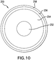
- the exemplary cable 250 includes a conductor 252 which may be made of copper, such as oxygen free high thermal conductivity ("OFHC") copper.
- the conductor 250 is surrounded by an insulator 254, such as SiO 2 dielectric material, separating the conductor 250 from jacket 256, which may also be made of OFHC copper.
- the insulator 254, in particular the SiO 2 dielectric has electrical properties that are approximately stable over the required manufacturing temperatures of the wired pipe 10.
- the line 250 is protected by an outer tube 258 providing a high range of performance temperatures and excellent mechanical resistance, such as a stainless steel or titanium.
- the materials for the line 250 may be radiation hardened and thermally stable, and the phase and insertion losses of the line 250 are low.
- the SiO 2 cable 250 which has similar electrical properties of a PTFE cable, can be 30-50% smaller and lighter than PTFE cable, and greater thermal resistance than PTFE cable. The smaller size renders the cable 250 more suitable for use in the wall of pipe body 12, 112, 212.
- PTFE has a much lower melting temperature (less than 350° C) than stainless steel (approximately 1500° C) and titanium (approximately 1650° C).
- the resultant cable 250 with its smaller dimensions and greater thermal resistance is suitable for extrusion within the wall 18, 118, 218 of the wired pipe 10.
- the helical wire channels 16, 116, 216 could be extruded within the wall 18, 118, 218 of the pipe body 12, 112, 212 by a piercing rod and the line subsequently inserted therein.
- FIG. 1 an extrusion process for forming a wired pipe body 12 as shown in FIG. 1 will be described, where the pipe body 12 includes two helically arranged wire channels 16 which protrude radially inward towards the interior 30 of the pipe body 12. Similar processes may be performed to form the pipe bodies 112, 212 shown in FIGS. 2 and 3 , as well as a pipe body including a single channel, or pipe bodies having more than two wire channels.
- FIG. 4 illustrates a first exemplary embodiment of a manufacturing tool 50 for an extrusion process to form the pipe body 12 shown in FIG. 1 .
- the tool 50 includes a housing 52 having an interior space 54 sized to hold raw material prior to the extrusion process.
- the tool 50 also includes an inner surface forming element, such as a first piercing rod 56, and first and second lines or conduits, or second and third piercing rods, represented at 58.
- the seamless wired pipe body 12 shown in FIG. 1 can be formed using the tool 50 by drawing a solid billet between the piercing rod 56 and the housing 52 to create the hollow shell of the pipe body 12.
- the piercing rod 56 forms the flow channel 28 of the pipe body 12.
- second and third piercing rods 58 for forming the wire channels 16 may be used in which case a line may subsequently be inserted.
- a helical structure is beneficial so that the resulting load force is in the direction of the channel 28. Therefore piercing rods 58 for the wire channels 16 may be helically arranged as well.
- a first end 60 of the first piercing rod 56 has an outer surface 62 substantially the same size and shape as the inner surface 24 of the pipe body 12 to be formed.
- the outer surface 62 of the first end 60 is further provided with indentations 64 corresponding to the inward radial protrusions to be formed by the inner surface 24 at the wire channels 16.
- the outer surface 62 of the first end 60 of the piercing rod 56 and an inner surface 66 of the housing 52 form a die of the tool 50.
- the first piercing rod 56 may have a tapered section 68 extending from the first end 60.
- the tapered section 68 allows raw material within the housing 52 to be extruded into the final shape of the pipe body 12 defined in part by the die.
- the first piercing rod 56 further includes an extension portion 70 extending through the interior space 54 of the housing 52.
- the first piercing rod 56 is configured to rotate during the extrusion process to form the wall 18 to accommodate the helically arranged wire channels 16, such as via rotation of the extension portion 70.
- the piercing rod 56 may be drawn back in direction A towards the raw material disposed within the interior space 54 of the housing 52 and/or a ram 72 may push the billet or raw material in direction B towards an opposite end of the housing 52.
- the piercing rod 56 is rotated to allow the wire channel 16 to be created at the appropriate helical angle and the billet or raw material is extruded through the extrusion gap 74 between the first end 60 of the piercing rod 56 and the inner surface 66 of the housing 52.
- the ends of piercing rods 58 are taken out. Therefore the pipe body has to be turned relative to the tool.
- the line is embedded in the pipe body during manufacturing of the pipe body 12, the line will be longer than what is shown at 58 in FIG. 4 to ensure adequate length for connection to other pipe bodies 12 and interconnecting couplers.
- a weak material with a low melting temperature such as but not limited to wax, can be used to hold the line 58 in place before the tube material surrounds it during the extrusion process.
- the manufacturing tool 50 is cooled, such as via cooling channels in the housing 52 and/or the piercing rod 56, or via cooling baths or air supplies to prevent the hollow extruded pipe body 12 from collapsing and the manufacturing tool from melting abrasion and deformations.
- FIGS. 5-8 Another exemplary embodiment of a manufacturing tool 150 for use in forming an integrated wired pipe body 12 is shown in FIGS. 5-8 .
- the tool 150 is usable in an embodiment where the raw material is in a melted state prior to extrusion.
- the tool 150 includes a housing 152.
- An inlet 176 ( FIG. 6 ) to an interior 154 of the housing 152 is arranged to receive melted raw material via a raw material introduction tube 178 ( FIGS. 7 and 8 ).
- the inlet 176 includes apertures 180 sized to allow the entry of the raw material, as well as aperture support webs 182 extending into the interior 154 of the housing 152 and supporting an inner surface forming element, such as a mandrel 156, therein.
- the mandrel 156 includes a first end 160 having an outer surface 162 similar to the outer surface 62 of the piercing rod shown in FIG. 4 .
- the outer surface 162 of the first end 160 of the mandrel 156 may have indentations 164 to create the radially inward protruding wall 18 adjacent the ware channel 16 of the pipe body 12 shown in FIG. 1 .
- the mandrel 156 is tapered towards a second end 184 ( FIG.
- the lines 158 are introduced between the housing 152 and the raw material introduction tube 178, as shown in FIGS. 7 and 8 .
- the lines 158 are provided with a connection portion 186 extending beyond the extruded pipe body 12 for subsequent connection with a joint or coupler, as will be further described below with respect to FIG. 9 .
- An extrusion gap 174 is formed between the inner surface 166 of the housing 152 and the outer surface 162 of the first end 160 of the mandrel 156, such that the extruded pipe body 12 has an outer surface 22 matching the inner surface 166 of the housing 152 at the extrusion gap 174 and an inner surface 24 matching the outer surface 162 of the first end 160 of the mandrel 156.
- the housing 152 with mandrel 156 may be rotated relative to the raw material introduction tube 178 to helically arrange the lines 158 within the wall 18 of the pipe body 12. It should be understood that the rotation is a result of pressing the material through the helical structure of the tool. That is, there is no active rotation of the raw material.
- the extruded pipe body 12 is cooled following extrusion to retain the shape and structure of the extruded pipe body 12 exiting the tool 150.
- the wired pipe 10 is ready for connection to other wired pipes 10. This may be accomplished through the use of a coupler, such as the exemplary embodiment of a tool joint 80 depicted in FIG. 9 .
- the tool joint 80 may be attached to an end of the helical channeled wired pipe 10, such as by welding, frictional welding, or other attachment methods.
- the joints 80 may be provided with bores 82 to pass the connection portions 186 of the lines 158 there through.
- the bores 82 may be gun drilled.
- the wired pipe 10 and joint 80 are aligned such that, at the final position of the welding process, the openings 84 to the bores 82 in the tool joint 80 and the openings 32 ( FIG. 1 ) of the channel 16 for the line 158 in the pipe body 12 are aligned. Afterwards the end of the bores 82 could be re-drilled, if necessary. It is also possible to route the lines 158 through the channel 16 after finishing the channel 16 or to connect the wire in the pipe body 12 after re-drilling with another wire routed through the tool joint 80. Another option would be to drill the bores 82 through the tool joint 80 after attaching the tool joint 80 to the pipe body 12. In this case the final orientation of the tool joint 80 relative to the pipe body 12 after the attachment would not matter.
- the tool joint 80 may include a threaded end portion 86.
- the threaded end portion 86 may include male or female threads, and a tool joint (not shown) having the other of male or female threads can be connected to an opposite end of the wired pipe 10.
- the tool joint 80 also includes a flow channel 88 aligned with the flow channel 28 after connection to the wired pipe 10.
- first, second, etc. do not denote any order or importance, but rather the terms first, second, etc. are used to distinguish one element from another.
- the use of the terms a, an, etc. do not denote a limitation of quantity, but rather denote the presence of at least one of the referenced item.
Landscapes
- Engineering & Computer Science (AREA)
- Mechanical Engineering (AREA)
- Life Sciences & Earth Sciences (AREA)
- Geology (AREA)
- Mining & Mineral Resources (AREA)
- Physics & Mathematics (AREA)
- Environmental & Geological Engineering (AREA)
- Fluid Mechanics (AREA)
- General Life Sciences & Earth Sciences (AREA)
- Geochemistry & Mineralogy (AREA)
- Rigid Pipes And Flexible Pipes (AREA)
- Details Of Indoor Wiring (AREA)
Applications Claiming Priority (2)
| Application Number | Priority Date | Filing Date | Title |
|---|---|---|---|
| US14/087,422 US9512682B2 (en) | 2013-11-22 | 2013-11-22 | Wired pipe and method of manufacturing wired pipe |
| PCT/US2014/066841 WO2015077575A1 (en) | 2013-11-22 | 2014-11-21 | Wired pipe and method of manufacturing wired pipe |
Publications (3)
| Publication Number | Publication Date |
|---|---|
| EP3071790A1 EP3071790A1 (en) | 2016-09-28 |
| EP3071790A4 EP3071790A4 (en) | 2017-10-04 |
| EP3071790B1 true EP3071790B1 (en) | 2022-06-01 |
Family
ID=53180188
Family Applications (1)
| Application Number | Title | Priority Date | Filing Date |
|---|---|---|---|
| EP14863193.0A Active EP3071790B1 (en) | 2013-11-22 | 2014-11-21 | Wired pipe and method of manufacturing wired pipe |
Country Status (5)
| Country | Link |
|---|---|
| US (1) | US9512682B2 (https=) |
| EP (1) | EP3071790B1 (https=) |
| CN (1) | CN105940186B (https=) |
| BR (1) | BR112016011607B1 (https=) |
| WO (1) | WO2015077575A1 (https=) |
Families Citing this family (6)
| Publication number | Priority date | Publication date | Assignee | Title |
|---|---|---|---|---|
| US9868258B2 (en) * | 2014-09-16 | 2018-01-16 | Baker Hughes, A Ge Company, Llc | Manufactured ported mandrel and method for making same |
| WO2018112647A1 (en) * | 2016-12-23 | 2018-06-28 | Evolution Engineering Inc. | Downhole probe sleeves and methods for making probe sleeves |
| CN109441371B (zh) * | 2018-11-26 | 2023-12-08 | 中国石油大学(北京) | 内旋式导管承载力加强装置及其使用方法 |
| US12129756B2 (en) | 2021-06-18 | 2024-10-29 | Baker Hughes Holdings Llc | Casing-embedded fiber-optics telemetry for real-time well integrity monitoring |
| CN114526003A (zh) * | 2022-03-11 | 2022-05-24 | 平顶山市安泰华矿用安全设备制造有限公司 | 一种动力钻头机构 |
| CN120350899B (zh) * | 2025-06-19 | 2025-10-28 | 德州联合石油科技股份有限公司 | 一种通讯用穿线钻杆 |
Citations (1)
| Publication number | Priority date | Publication date | Assignee | Title |
|---|---|---|---|---|
| US20110017334A1 (en) * | 2009-07-23 | 2011-01-27 | Baker Hughes Incorporated | Wired conduit segment and method of making same |
Family Cites Families (39)
| Publication number | Priority date | Publication date | Assignee | Title |
|---|---|---|---|---|
| GB778614A (en) * | 1953-11-24 | 1957-07-10 | Krauss Maffei Ag | Improvements in or relating to apparatus for manufacturing reinforced tubular or flexible tubular articles |
| IT987983B (it) * | 1973-05-29 | 1975-03-20 | Tamborini G | Procedimento e dispositivo per la fabbricazione di estrusi in materiale termoplastico rinfor zati mediante filo metallico ad elica in particolare tubi |
| US4095865A (en) | 1977-05-23 | 1978-06-20 | Shell Oil Company | Telemetering drill string with piped electrical conductor |
| US4121193A (en) | 1977-06-23 | 1978-10-17 | Shell Oil Company | Kelly and kelly cock assembly for hard-wired telemetry system |
| GB1571677A (en) | 1978-04-07 | 1980-07-16 | Shell Int Research | Pipe section for use in a borehole |
| US4788544A (en) | 1987-01-08 | 1988-11-29 | Hughes Tool Company - Usa | Well bore data transmission system |
| US4884071A (en) | 1987-01-08 | 1989-11-28 | Hughes Tool Company | Wellbore tool with hall effect coupling |
| US5748565A (en) | 1996-09-26 | 1998-05-05 | Litton Systems, Inc. | Flexible interlink for hydrophone array |
| US6004639A (en) * | 1997-10-10 | 1999-12-21 | Fiberspar Spoolable Products, Inc. | Composite spoolable tube with sensor |
| US9284780B2 (en) * | 2001-08-19 | 2016-03-15 | Smart Drilling And Completion, Inc. | Drilling apparatus |
| US7361835B2 (en) * | 2001-11-20 | 2008-04-22 | Commscope, Inc. Of North America | Toneable conduit and method of preparing same |
| US20030094298A1 (en) | 2001-11-20 | 2003-05-22 | Commscope Properties, Llc | Toneable conduit and method of preparing same |
| JP2003258510A (ja) * | 2002-02-26 | 2003-09-12 | Matsushita Electric Ind Co Ltd | 有線伝送路 |
| US6799632B2 (en) | 2002-08-05 | 2004-10-05 | Intelliserv, Inc. | Expandable metal liner for downhole components |
| AU2003274318A1 (en) | 2002-10-10 | 2004-05-04 | Lucas, Brian, Ronald | Apparatus and method for transmitting a signal in a wellbore |
| US6982384B2 (en) | 2003-09-25 | 2006-01-03 | Intelliserv, Inc. | Load-resistant coaxial transmission line |
| US7852232B2 (en) | 2003-02-04 | 2010-12-14 | Intelliserv, Inc. | Downhole tool adapted for telemetry |
| US6981546B2 (en) | 2003-06-09 | 2006-01-03 | Intelliserv, Inc. | Electrical transmission line diametrical retention mechanism |
| US6877781B2 (en) * | 2003-07-31 | 2005-04-12 | Highlands Corporation | Corrugated tube fitting |
| US7390032B2 (en) * | 2003-08-01 | 2008-06-24 | Sonstone Corporation | Tubing joint of multiple orientations containing electrical wiring |
| US6991035B2 (en) | 2003-09-02 | 2006-01-31 | Intelliserv, Inc. | Drilling jar for use in a downhole network |
| US7017667B2 (en) | 2003-10-31 | 2006-03-28 | Intelliserv, Inc. | Drill string transmission line |
| US7291303B2 (en) | 2003-12-31 | 2007-11-06 | Intelliserv, Inc. | Method for bonding a transmission line to a downhole tool |
| US7523765B2 (en) | 2004-02-27 | 2009-04-28 | Fiberspar Corporation | Fiber reinforced spoolable pipe |
| US7617873B2 (en) * | 2004-05-28 | 2009-11-17 | Schlumberger Technology Corporation | System and methods using fiber optics in coiled tubing |
| US7311154B2 (en) * | 2004-07-01 | 2007-12-25 | Schlumberger Technology Corporation | Line slack compensator |
| US7413021B2 (en) * | 2005-03-31 | 2008-08-19 | Schlumberger Technology Corporation | Method and conduit for transmitting signals |
| US7777644B2 (en) * | 2005-12-12 | 2010-08-17 | InatelliServ, LLC | Method and conduit for transmitting signals |
| US7605715B2 (en) | 2006-07-10 | 2009-10-20 | Schlumberger Technology Corporation | Electromagnetic wellbore telemetry system for tubular strings |
| US7527105B2 (en) | 2006-11-14 | 2009-05-05 | Hall David R | Power and/or data connection in a downhole component |
| FR2936554B1 (fr) | 2008-09-30 | 2010-10-29 | Vam Drilling France | Element de garniture de forage a instruments |
| NO2236736T3 (https=) | 2009-03-30 | 2018-05-12 | ||
| US20100264646A1 (en) | 2009-04-16 | 2010-10-21 | Jean-Marc Follini | Structures for wire routing in wired drill pipe |
| BRPI0924988B1 (pt) | 2009-05-07 | 2019-05-21 | Vam Drilling France | Dispositivo de fixação, componente de coluna de perfuração tubular e método para instalar o dispositivo de fixação |
| US9359874B2 (en) | 2010-07-09 | 2016-06-07 | Halliburton Energy Services, Inc. | Systems and methods for killing a well |
| EP2681401B1 (en) | 2011-03-01 | 2018-10-17 | Vallourec Drilling Products France | Tubular component for drill stem capable of being cabled, and method for mounting a cable in said component |
| FR2981394B1 (fr) | 2011-10-14 | 2013-11-01 | Vam Drilling France | Composant tubulaire de garniture de forage muni d'une gaine de transmission fixee par filetages et procede de montage d'un tel composant |
| US9255451B2 (en) * | 2013-01-29 | 2016-02-09 | Baker Hughes Incorporated | Tube locking mechanism for downhole components |
| CN105264172B (zh) * | 2013-08-20 | 2018-12-21 | 哈利伯顿能源服务公司 | 具有光纤的井下钻探最优化钻环 |
-
2013
- 2013-11-22 US US14/087,422 patent/US9512682B2/en active Active
-
2014
- 2014-11-21 WO PCT/US2014/066841 patent/WO2015077575A1/en not_active Ceased
- 2014-11-21 EP EP14863193.0A patent/EP3071790B1/en active Active
- 2014-11-21 CN CN201480071129.XA patent/CN105940186B/zh active Active
- 2014-11-21 BR BR112016011607-0A patent/BR112016011607B1/pt active IP Right Grant
Patent Citations (1)
| Publication number | Priority date | Publication date | Assignee | Title |
|---|---|---|---|---|
| US20110017334A1 (en) * | 2009-07-23 | 2011-01-27 | Baker Hughes Incorporated | Wired conduit segment and method of making same |
Also Published As
| Publication number | Publication date |
|---|---|
| BR112016011607A2 (https=) | 2017-08-08 |
| BR112016011607B1 (pt) | 2022-01-04 |
| EP3071790A1 (en) | 2016-09-28 |
| CN105940186A (zh) | 2016-09-14 |
| WO2015077575A1 (en) | 2015-05-28 |
| EP3071790A4 (en) | 2017-10-04 |
| CN105940186B (zh) | 2020-04-24 |
| US9512682B2 (en) | 2016-12-06 |
| US20150144324A1 (en) | 2015-05-28 |
Similar Documents
| Publication | Publication Date | Title |
|---|---|---|
| EP3071790B1 (en) | Wired pipe and method of manufacturing wired pipe | |
| CN1880721B (zh) | 用于传输信号的方法和管道 | |
| US7478651B2 (en) | Bore-lining tubing | |
| US10100586B2 (en) | Downhole electrical connector | |
| US7859426B2 (en) | Electromagnetic wellbore telemetry system for tubular strings | |
| US8696034B2 (en) | Composite drill pipe and method for forming same | |
| US9044798B2 (en) | Wired conduit segment and method of making same | |
| US7299867B2 (en) | Hanger mounted in the bore of a tubular component | |
| US10760349B2 (en) | Method of forming a wired pipe transmission line | |
| CN112392410B (zh) | 一种柔性电连接钻柱 | |
| CN101082267A (zh) | 传输信号的方法和管道 | |
| US9255451B2 (en) | Tube locking mechanism for downhole components | |
| EP3025008B1 (en) | Shoulder ring for transmission line and transmission devices | |
| CN102191918B (zh) | 用于井下工具的偏移接头 | |
| CN121712961A (zh) | 具有改进的电接触件的电导体的井管 | |
| CN117178103A (zh) | 具有流体隔离的导电路径的完井管 |
Legal Events
| Date | Code | Title | Description |
|---|---|---|---|
| PUAI | Public reference made under article 153(3) epc to a published international application that has entered the european phase |
Free format text: ORIGINAL CODE: 0009012 |
|
| 17P | Request for examination filed |
Effective date: 20160614 |
|
| AK | Designated contracting states |
Kind code of ref document: A1 Designated state(s): AL AT BE BG CH CY CZ DE DK EE ES FI FR GB GR HR HU IE IS IT LI LT LU LV MC MK MT NL NO PL PT RO RS SE SI SK SM TR |
|
| AX | Request for extension of the european patent |
Extension state: BA ME |
|
| DAX | Request for extension of the european patent (deleted) | ||
| A4 | Supplementary search report drawn up and despatched |
Effective date: 20170831 |
|
| RIC1 | Information provided on ipc code assigned before grant |
Ipc: B21C 23/00 20060101ALI20170825BHEP Ipc: B29C 47/00 20060101ALN20170825BHEP Ipc: E21B 17/00 20060101ALI20170825BHEP Ipc: B29C 47/10 20060101AFI20170825BHEP Ipc: E21B 47/12 20120101ALN20170825BHEP |
|
| RAP1 | Party data changed (applicant data changed or rights of an application transferred) |
Owner name: BAKER HUGHES, A GE COMPANY, LLC |
|
| STAA | Information on the status of an ep patent application or granted ep patent |
Free format text: STATUS: EXAMINATION IS IN PROGRESS |
|
| 17Q | First examination report despatched |
Effective date: 20190117 |
|
| RAP1 | Party data changed (applicant data changed or rights of an application transferred) |
Owner name: JDI INTERNATIONAL LEASING LIMITED |
|
| RAP1 | Party data changed (applicant data changed or rights of an application transferred) |
Owner name: BAKER HUGHES VENTURES & GROWTH LLC |
|
| REG | Reference to a national code |
Ref country code: DE Ref legal event code: R079 Ref document number: 602014083917 Country of ref document: DE Free format text: PREVIOUS MAIN CLASS: E21B0047120000 Ipc: B21C0023000000 |
|
| GRAP | Despatch of communication of intention to grant a patent |
Free format text: ORIGINAL CODE: EPIDOSNIGR1 |
|
| STAA | Information on the status of an ep patent application or granted ep patent |
Free format text: STATUS: GRANT OF PATENT IS INTENDED |
|
| RIC1 | Information provided on ipc code assigned before grant |
Ipc: E21B 47/12 20120101ALN20211216BHEP Ipc: B21C 25/04 20060101ALI20211216BHEP Ipc: B21C 23/08 20060101ALI20211216BHEP Ipc: B21C 37/15 20060101ALI20211216BHEP Ipc: E21B 17/00 20060101ALI20211216BHEP Ipc: B21C 23/00 20060101AFI20211216BHEP |
|
| INTG | Intention to grant announced |
Effective date: 20220105 |
|
| GRAS | Grant fee paid |
Free format text: ORIGINAL CODE: EPIDOSNIGR3 |
|
| GRAA | (expected) grant |
Free format text: ORIGINAL CODE: 0009210 |
|
| STAA | Information on the status of an ep patent application or granted ep patent |
Free format text: STATUS: THE PATENT HAS BEEN GRANTED |
|
| AK | Designated contracting states |
Kind code of ref document: B1 Designated state(s): AL AT BE BG CH CY CZ DE DK EE ES FI FR GB GR HR HU IE IS IT LI LT LU LV MC MK MT NL NO PL PT RO RS SE SI SK SM TR |
|
| REG | Reference to a national code |
Ref country code: GB Ref legal event code: FG4D |
|
| REG | Reference to a national code |
Ref country code: AT Ref legal event code: REF Ref document number: 1495021 Country of ref document: AT Kind code of ref document: T Effective date: 20220615 Ref country code: CH Ref legal event code: EP |
|
| REG | Reference to a national code |
Ref country code: IE Ref legal event code: FG4D |
|
| REG | Reference to a national code |
Ref country code: DE Ref legal event code: R096 Ref document number: 602014083917 Country of ref document: DE |
|
| REG | Reference to a national code |
Ref country code: NO Ref legal event code: T2 Effective date: 20220601 |
|
| REG | Reference to a national code |
Ref country code: LT Ref legal event code: MG9D |
|
| REG | Reference to a national code |
Ref country code: NL Ref legal event code: MP Effective date: 20220601 |
|
| PG25 | Lapsed in a contracting state [announced via postgrant information from national office to epo] |
Ref country code: SE Free format text: LAPSE BECAUSE OF FAILURE TO SUBMIT A TRANSLATION OF THE DESCRIPTION OR TO PAY THE FEE WITHIN THE PRESCRIBED TIME-LIMIT Effective date: 20220601 Ref country code: LT Free format text: LAPSE BECAUSE OF FAILURE TO SUBMIT A TRANSLATION OF THE DESCRIPTION OR TO PAY THE FEE WITHIN THE PRESCRIBED TIME-LIMIT Effective date: 20220601 Ref country code: HR Free format text: LAPSE BECAUSE OF FAILURE TO SUBMIT A TRANSLATION OF THE DESCRIPTION OR TO PAY THE FEE WITHIN THE PRESCRIBED TIME-LIMIT Effective date: 20220601 Ref country code: GR Free format text: LAPSE BECAUSE OF FAILURE TO SUBMIT A TRANSLATION OF THE DESCRIPTION OR TO PAY THE FEE WITHIN THE PRESCRIBED TIME-LIMIT Effective date: 20220902 Ref country code: FI Free format text: LAPSE BECAUSE OF FAILURE TO SUBMIT A TRANSLATION OF THE DESCRIPTION OR TO PAY THE FEE WITHIN THE PRESCRIBED TIME-LIMIT Effective date: 20220601 Ref country code: ES Free format text: LAPSE BECAUSE OF FAILURE TO SUBMIT A TRANSLATION OF THE DESCRIPTION OR TO PAY THE FEE WITHIN THE PRESCRIBED TIME-LIMIT Effective date: 20220601 Ref country code: BG Free format text: LAPSE BECAUSE OF FAILURE TO SUBMIT A TRANSLATION OF THE DESCRIPTION OR TO PAY THE FEE WITHIN THE PRESCRIBED TIME-LIMIT Effective date: 20220901 |
|
| REG | Reference to a national code |
Ref country code: AT Ref legal event code: MK05 Ref document number: 1495021 Country of ref document: AT Kind code of ref document: T Effective date: 20220601 |
|
| PG25 | Lapsed in a contracting state [announced via postgrant information from national office to epo] |
Ref country code: RS Free format text: LAPSE BECAUSE OF FAILURE TO SUBMIT A TRANSLATION OF THE DESCRIPTION OR TO PAY THE FEE WITHIN THE PRESCRIBED TIME-LIMIT Effective date: 20220601 Ref country code: PL Free format text: LAPSE BECAUSE OF FAILURE TO SUBMIT A TRANSLATION OF THE DESCRIPTION OR TO PAY THE FEE WITHIN THE PRESCRIBED TIME-LIMIT Effective date: 20220601 Ref country code: LV Free format text: LAPSE BECAUSE OF FAILURE TO SUBMIT A TRANSLATION OF THE DESCRIPTION OR TO PAY THE FEE WITHIN THE PRESCRIBED TIME-LIMIT Effective date: 20220601 |
|
| PG25 | Lapsed in a contracting state [announced via postgrant information from national office to epo] |
Ref country code: NL Free format text: LAPSE BECAUSE OF FAILURE TO SUBMIT A TRANSLATION OF THE DESCRIPTION OR TO PAY THE FEE WITHIN THE PRESCRIBED TIME-LIMIT Effective date: 20220601 |
|
| PG25 | Lapsed in a contracting state [announced via postgrant information from national office to epo] |
Ref country code: SM Free format text: LAPSE BECAUSE OF FAILURE TO SUBMIT A TRANSLATION OF THE DESCRIPTION OR TO PAY THE FEE WITHIN THE PRESCRIBED TIME-LIMIT Effective date: 20220601 Ref country code: SK Free format text: LAPSE BECAUSE OF FAILURE TO SUBMIT A TRANSLATION OF THE DESCRIPTION OR TO PAY THE FEE WITHIN THE PRESCRIBED TIME-LIMIT Effective date: 20220601 Ref country code: RO Free format text: LAPSE BECAUSE OF FAILURE TO SUBMIT A TRANSLATION OF THE DESCRIPTION OR TO PAY THE FEE WITHIN THE PRESCRIBED TIME-LIMIT Effective date: 20220601 Ref country code: PT Free format text: LAPSE BECAUSE OF FAILURE TO SUBMIT A TRANSLATION OF THE DESCRIPTION OR TO PAY THE FEE WITHIN THE PRESCRIBED TIME-LIMIT Effective date: 20221003 Ref country code: EE Free format text: LAPSE BECAUSE OF FAILURE TO SUBMIT A TRANSLATION OF THE DESCRIPTION OR TO PAY THE FEE WITHIN THE PRESCRIBED TIME-LIMIT Effective date: 20220601 Ref country code: CZ Free format text: LAPSE BECAUSE OF FAILURE TO SUBMIT A TRANSLATION OF THE DESCRIPTION OR TO PAY THE FEE WITHIN THE PRESCRIBED TIME-LIMIT Effective date: 20220601 Ref country code: AT Free format text: LAPSE BECAUSE OF FAILURE TO SUBMIT A TRANSLATION OF THE DESCRIPTION OR TO PAY THE FEE WITHIN THE PRESCRIBED TIME-LIMIT Effective date: 20220601 |
|
| PG25 | Lapsed in a contracting state [announced via postgrant information from national office to epo] |
Ref country code: IS Free format text: LAPSE BECAUSE OF FAILURE TO SUBMIT A TRANSLATION OF THE DESCRIPTION OR TO PAY THE FEE WITHIN THE PRESCRIBED TIME-LIMIT Effective date: 20221001 |
|
| REG | Reference to a national code |
Ref country code: DE Ref legal event code: R097 Ref document number: 602014083917 Country of ref document: DE |
|
| PG25 | Lapsed in a contracting state [announced via postgrant information from national office to epo] |
Ref country code: AL Free format text: LAPSE BECAUSE OF FAILURE TO SUBMIT A TRANSLATION OF THE DESCRIPTION OR TO PAY THE FEE WITHIN THE PRESCRIBED TIME-LIMIT Effective date: 20220601 |
|
| PLBE | No opposition filed within time limit |
Free format text: ORIGINAL CODE: 0009261 |
|
| STAA | Information on the status of an ep patent application or granted ep patent |
Free format text: STATUS: NO OPPOSITION FILED WITHIN TIME LIMIT |
|
| PG25 | Lapsed in a contracting state [announced via postgrant information from national office to epo] |
Ref country code: DK Free format text: LAPSE BECAUSE OF FAILURE TO SUBMIT A TRANSLATION OF THE DESCRIPTION OR TO PAY THE FEE WITHIN THE PRESCRIBED TIME-LIMIT Effective date: 20220601 |
|
| 26N | No opposition filed |
Effective date: 20230302 |
|
| PG25 | Lapsed in a contracting state [announced via postgrant information from national office to epo] |
Ref country code: SI Free format text: LAPSE BECAUSE OF FAILURE TO SUBMIT A TRANSLATION OF THE DESCRIPTION OR TO PAY THE FEE WITHIN THE PRESCRIBED TIME-LIMIT Effective date: 20220601 |
|
| REG | Reference to a national code |
Ref country code: DE Ref legal event code: R119 Ref document number: 602014083917 Country of ref document: DE |
|
| PG25 | Lapsed in a contracting state [announced via postgrant information from national office to epo] |
Ref country code: MC Free format text: LAPSE BECAUSE OF FAILURE TO SUBMIT A TRANSLATION OF THE DESCRIPTION OR TO PAY THE FEE WITHIN THE PRESCRIBED TIME-LIMIT Effective date: 20220601 |
|
| REG | Reference to a national code |
Ref country code: CH Ref legal event code: PL |
|
| P01 | Opt-out of the competence of the unified patent court (upc) registered |
Effective date: 20230526 |
|
| REG | Reference to a national code |
Ref country code: BE Ref legal event code: MM Effective date: 20221130 |
|
| PG25 | Lapsed in a contracting state [announced via postgrant information from national office to epo] |
Ref country code: LI Free format text: LAPSE BECAUSE OF NON-PAYMENT OF DUE FEES Effective date: 20221130 Ref country code: CH Free format text: LAPSE BECAUSE OF NON-PAYMENT OF DUE FEES Effective date: 20221130 |
|
| PG25 | Lapsed in a contracting state [announced via postgrant information from national office to epo] |
Ref country code: LU Free format text: LAPSE BECAUSE OF NON-PAYMENT OF DUE FEES Effective date: 20221121 |
|
| PG25 | Lapsed in a contracting state [announced via postgrant information from national office to epo] |
Ref country code: IE Free format text: LAPSE BECAUSE OF NON-PAYMENT OF DUE FEES Effective date: 20221121 Ref country code: DE Free format text: LAPSE BECAUSE OF NON-PAYMENT OF DUE FEES Effective date: 20230601 |
|
| PG25 | Lapsed in a contracting state [announced via postgrant information from national office to epo] |
Ref country code: FR Free format text: LAPSE BECAUSE OF NON-PAYMENT OF DUE FEES Effective date: 20221130 Ref country code: BE Free format text: LAPSE BECAUSE OF NON-PAYMENT OF DUE FEES Effective date: 20221130 |
|
| PG25 | Lapsed in a contracting state [announced via postgrant information from national office to epo] |
Ref country code: IT Free format text: LAPSE BECAUSE OF FAILURE TO SUBMIT A TRANSLATION OF THE DESCRIPTION OR TO PAY THE FEE WITHIN THE PRESCRIBED TIME-LIMIT Effective date: 20220601 |
|
| PG25 | Lapsed in a contracting state [announced via postgrant information from national office to epo] |
Ref country code: HU Free format text: LAPSE BECAUSE OF FAILURE TO SUBMIT A TRANSLATION OF THE DESCRIPTION OR TO PAY THE FEE WITHIN THE PRESCRIBED TIME-LIMIT; INVALID AB INITIO Effective date: 20141121 |
|
| PG25 | Lapsed in a contracting state [announced via postgrant information from national office to epo] |
Ref country code: CY Free format text: LAPSE BECAUSE OF FAILURE TO SUBMIT A TRANSLATION OF THE DESCRIPTION OR TO PAY THE FEE WITHIN THE PRESCRIBED TIME-LIMIT Effective date: 20220601 |
|
| PG25 | Lapsed in a contracting state [announced via postgrant information from national office to epo] |
Ref country code: MK Free format text: LAPSE BECAUSE OF FAILURE TO SUBMIT A TRANSLATION OF THE DESCRIPTION OR TO PAY THE FEE WITHIN THE PRESCRIBED TIME-LIMIT Effective date: 20220601 |
|
| PG25 | Lapsed in a contracting state [announced via postgrant information from national office to epo] |
Ref country code: MT Free format text: LAPSE BECAUSE OF FAILURE TO SUBMIT A TRANSLATION OF THE DESCRIPTION OR TO PAY THE FEE WITHIN THE PRESCRIBED TIME-LIMIT Effective date: 20220601 |
|
| PG25 | Lapsed in a contracting state [announced via postgrant information from national office to epo] |
Ref country code: BG Free format text: LAPSE BECAUSE OF FAILURE TO SUBMIT A TRANSLATION OF THE DESCRIPTION OR TO PAY THE FEE WITHIN THE PRESCRIBED TIME-LIMIT Effective date: 20220601 |
|
| PG25 | Lapsed in a contracting state [announced via postgrant information from national office to epo] |
Ref country code: BG Free format text: LAPSE BECAUSE OF FAILURE TO SUBMIT A TRANSLATION OF THE DESCRIPTION OR TO PAY THE FEE WITHIN THE PRESCRIBED TIME-LIMIT Effective date: 20220601 |
|
| PG25 | Lapsed in a contracting state [announced via postgrant information from national office to epo] |
Ref country code: TR Free format text: LAPSE BECAUSE OF FAILURE TO SUBMIT A TRANSLATION OF THE DESCRIPTION OR TO PAY THE FEE WITHIN THE PRESCRIBED TIME-LIMIT Effective date: 20220601 |
|
| PGFP | Annual fee paid to national office [announced via postgrant information from national office to epo] |
Ref country code: GB Payment date: 20251023 Year of fee payment: 12 |
|
| PGFP | Annual fee paid to national office [announced via postgrant information from national office to epo] |
Ref country code: NO Payment date: 20251024 Year of fee payment: 12 |