EP3071123B1 - System zur freisetzung von befestigungselementen mit mehrfachauslösung - Google Patents
System zur freisetzung von befestigungselementen mit mehrfachauslösung Download PDFInfo
- Publication number
- EP3071123B1 EP3071123B1 EP14862952.0A EP14862952A EP3071123B1 EP 3071123 B1 EP3071123 B1 EP 3071123B1 EP 14862952 A EP14862952 A EP 14862952A EP 3071123 B1 EP3071123 B1 EP 3071123B1
- Authority
- EP
- European Patent Office
- Prior art keywords
- fastener
- applier
- fasteners
- control circuit
- shaft
- Prior art date
- Legal status (The legal status is an assumption and is not a legal conclusion. Google has not performed a legal analysis and makes no representation as to the accuracy of the status listed.)
- Active
Links
- 230000002441 reversible effect Effects 0.000 claims description 28
- 230000007935 neutral effect Effects 0.000 claims description 9
- 230000004044 response Effects 0.000 claims description 7
- 238000000034 method Methods 0.000 description 24
- 210000000709 aorta Anatomy 0.000 description 23
- 210000002376 aorta thoracic Anatomy 0.000 description 16
- 238000002513 implantation Methods 0.000 description 15
- 208000002251 Dissecting Aneurysm Diseases 0.000 description 13
- 238000002224 dissection Methods 0.000 description 12
- 230000007246 mechanism Effects 0.000 description 11
- 229910001000 nickel titanium Inorganic materials 0.000 description 10
- 206010002329 Aneurysm Diseases 0.000 description 9
- 239000008280 blood Substances 0.000 description 8
- 210000004369 blood Anatomy 0.000 description 8
- 230000008569 process Effects 0.000 description 8
- 210000001519 tissue Anatomy 0.000 description 8
- 230000000007 visual effect Effects 0.000 description 8
- 208000007474 aortic aneurysm Diseases 0.000 description 7
- 238000010276 construction Methods 0.000 description 7
- 238000012790 confirmation Methods 0.000 description 6
- 229910052751 metal Inorganic materials 0.000 description 6
- 239000002184 metal Substances 0.000 description 6
- 150000002739 metals Chemical class 0.000 description 6
- 210000000056 organ Anatomy 0.000 description 6
- 239000004033 plastic Substances 0.000 description 6
- 229920003023 plastic Polymers 0.000 description 6
- 230000002792 vascular Effects 0.000 description 6
- 201000008982 Thoracic Aortic Aneurysm Diseases 0.000 description 5
- HZEWFHLRYVTOIW-UHFFFAOYSA-N [Ti].[Ni] Chemical compound [Ti].[Ni] HZEWFHLRYVTOIW-UHFFFAOYSA-N 0.000 description 5
- 206010002895 aortic dissection Diseases 0.000 description 5
- 210000001367 artery Anatomy 0.000 description 5
- 239000000919 ceramic Substances 0.000 description 5
- 239000007943 implant Substances 0.000 description 5
- 239000000463 material Substances 0.000 description 5
- HLXZNVUGXRDIFK-UHFFFAOYSA-N nickel titanium Chemical compound [Ti].[Ti].[Ti].[Ti].[Ti].[Ti].[Ti].[Ti].[Ti].[Ti].[Ti].[Ni].[Ni].[Ni].[Ni].[Ni].[Ni].[Ni].[Ni].[Ni].[Ni].[Ni].[Ni].[Ni].[Ni] HLXZNVUGXRDIFK-UHFFFAOYSA-N 0.000 description 5
- 229910001220 stainless steel Inorganic materials 0.000 description 5
- 239000010935 stainless steel Substances 0.000 description 5
- 210000003270 subclavian artery Anatomy 0.000 description 5
- 230000003187 abdominal effect Effects 0.000 description 4
- 230000005856 abnormality Effects 0.000 description 4
- 230000004397 blinking Effects 0.000 description 4
- 230000000977 initiatory effect Effects 0.000 description 4
- 238000003825 pressing Methods 0.000 description 4
- 210000002254 renal artery Anatomy 0.000 description 4
- 230000008439 repair process Effects 0.000 description 4
- 208000003457 familial thoracic 1 aortic aneurysm Diseases 0.000 description 3
- 230000033001 locomotion Effects 0.000 description 3
- 230000003287 optical effect Effects 0.000 description 3
- 210000000115 thoracic cavity Anatomy 0.000 description 3
- 210000000702 aorta abdominal Anatomy 0.000 description 2
- 238000005452 bending Methods 0.000 description 2
- 230000008901 benefit Effects 0.000 description 2
- 230000017531 blood circulation Effects 0.000 description 2
- 230000008859 change Effects 0.000 description 2
- 230000001010 compromised effect Effects 0.000 description 2
- 208000018631 connective tissue disease Diseases 0.000 description 2
- 230000006378 damage Effects 0.000 description 2
- 201000010099 disease Diseases 0.000 description 2
- 208000037265 diseases, disorders, signs and symptoms Diseases 0.000 description 2
- 239000011888 foil Substances 0.000 description 2
- 238000002355 open surgical procedure Methods 0.000 description 2
- 230000036961 partial effect Effects 0.000 description 2
- 238000001356 surgical procedure Methods 0.000 description 2
- 206010002889 Aortic aneurysms and dissections Diseases 0.000 description 1
- 201000001320 Atherosclerosis Diseases 0.000 description 1
- 206010020772 Hypertension Diseases 0.000 description 1
- 208000001826 Marfan syndrome Diseases 0.000 description 1
- 206010039203 Road traffic accident Diseases 0.000 description 1
- 208000002847 Surgical Wound Diseases 0.000 description 1
- 210000001015 abdomen Anatomy 0.000 description 1
- 210000003484 anatomy Anatomy 0.000 description 1
- 208000021654 bicuspid aortic valve disease Diseases 0.000 description 1
- 239000000560 biocompatible material Substances 0.000 description 1
- 230000015572 biosynthetic process Effects 0.000 description 1
- 230000000903 blocking effect Effects 0.000 description 1
- 230000036772 blood pressure Effects 0.000 description 1
- 210000004204 blood vessel Anatomy 0.000 description 1
- 210000002168 brachiocephalic trunk Anatomy 0.000 description 1
- 210000004556 brain Anatomy 0.000 description 1
- 210000001168 carotid artery common Anatomy 0.000 description 1
- 230000007850 degeneration Effects 0.000 description 1
- 230000001419 dependent effect Effects 0.000 description 1
- 230000004064 dysfunction Effects 0.000 description 1
- -1 e.g. Substances 0.000 description 1
- 230000007717 exclusion Effects 0.000 description 1
- 239000012530 fluid Substances 0.000 description 1
- 230000000004 hemodynamic effect Effects 0.000 description 1
- 208000014674 injury Diseases 0.000 description 1
- 230000007774 longterm Effects 0.000 description 1
- 238000004806 packaging method and process Methods 0.000 description 1
- 230000035515 penetration Effects 0.000 description 1
- 229920001296 polysiloxane Polymers 0.000 description 1
- 238000002360 preparation method Methods 0.000 description 1
- 230000001902 propagating effect Effects 0.000 description 1
- 230000000717 retained effect Effects 0.000 description 1
- 239000007787 solid Substances 0.000 description 1
- 210000000278 spinal cord Anatomy 0.000 description 1
- 208000024891 symptom Diseases 0.000 description 1
- 230000008733 trauma Effects 0.000 description 1
- 230000003313 weakening effect Effects 0.000 description 1
Images


Classifications
-
- A—HUMAN NECESSITIES
- A61—MEDICAL OR VETERINARY SCIENCE; HYGIENE
- A61B—DIAGNOSIS; SURGERY; IDENTIFICATION
- A61B17/00—Surgical instruments, devices or methods
- A61B17/068—Surgical staplers, e.g. containing multiple staples or clamps
-
- A—HUMAN NECESSITIES
- A61—MEDICAL OR VETERINARY SCIENCE; HYGIENE
- A61B—DIAGNOSIS; SURGERY; IDENTIFICATION
- A61B50/00—Containers, covers, furniture or holders specially adapted for surgical or diagnostic appliances or instruments, e.g. sterile covers
- A61B50/30—Containers specially adapted for packaging, protecting, dispensing, collecting or disposing of surgical or diagnostic appliances or instruments
-
- A—HUMAN NECESSITIES
- A61—MEDICAL OR VETERINARY SCIENCE; HYGIENE
- A61B—DIAGNOSIS; SURGERY; IDENTIFICATION
- A61B17/00—Surgical instruments, devices or methods
- A61B17/10—Surgical instruments, devices or methods for applying or removing wound clamps, e.g. containing only one clamp or staple; Wound clamp magazines
- A61B17/105—Wound clamp magazines
-
- A—HUMAN NECESSITIES
- A61—MEDICAL OR VETERINARY SCIENCE; HYGIENE
- A61B—DIAGNOSIS; SURGERY; IDENTIFICATION
- A61B17/00—Surgical instruments, devices or methods
- A61B2017/00017—Electrical control of surgical instruments
- A61B2017/00115—Electrical control of surgical instruments with audible or visual output
- A61B2017/00119—Electrical control of surgical instruments with audible or visual output alarm; indicating an abnormal situation
- A61B2017/00123—Electrical control of surgical instruments with audible or visual output alarm; indicating an abnormal situation and automatic shutdown
-
- A—HUMAN NECESSITIES
- A61—MEDICAL OR VETERINARY SCIENCE; HYGIENE
- A61B—DIAGNOSIS; SURGERY; IDENTIFICATION
- A61B17/00—Surgical instruments, devices or methods
- A61B2017/00367—Details of actuation of instruments, e.g. relations between pushing buttons, or the like, and activation of the tool, working tip, or the like
- A61B2017/00398—Details of actuation of instruments, e.g. relations between pushing buttons, or the like, and activation of the tool, working tip, or the like using powered actuators, e.g. stepper motors, solenoids
-
- A—HUMAN NECESSITIES
- A61—MEDICAL OR VETERINARY SCIENCE; HYGIENE
- A61B—DIAGNOSIS; SURGERY; IDENTIFICATION
- A61B17/00—Surgical instruments, devices or methods
- A61B2017/00681—Aspects not otherwise provided for
- A61B2017/00734—Aspects not otherwise provided for battery operated
-
- A—HUMAN NECESSITIES
- A61—MEDICAL OR VETERINARY SCIENCE; HYGIENE
- A61B—DIAGNOSIS; SURGERY; IDENTIFICATION
- A61B17/00—Surgical instruments, devices or methods
- A61B17/064—Surgical staples, i.e. penetrating the tissue
- A61B2017/0649—Coils or spirals
-
- A—HUMAN NECESSITIES
- A61—MEDICAL OR VETERINARY SCIENCE; HYGIENE
- A61B—DIAGNOSIS; SURGERY; IDENTIFICATION
- A61B90/00—Instruments, implements or accessories specially adapted for surgery or diagnosis and not covered by any of the groups A61B1/00 - A61B50/00, e.g. for luxation treatment or for protecting wound edges
- A61B90/08—Accessories or related features not otherwise provided for
- A61B2090/0803—Counting the number of times an instrument is used
Definitions
- Document EP 2 260 775 A2 discloses a surgical fastener applier capable of applying fasteners, having an actuation mechanism, a drive mechanism, and a control system.
- the actuation mechanism initiates movement of the drive mechanism through the controller.
- the surgical fastener applier includes a handle with an elongate member partially extending therefrom.
- the drive mechanism is partially encapsulated by the handle and extends at least partially through the elongate member
- the drive mechanism is connected with a fastening portion to eject a fastener from the surgical fastener applier.
- the surgical fastener applier may include one or more fasteners within a cartridge detachably coupled to the drive mechanism.
- the drive mechanism may include a motor and a power supply.
- a fastener delivery shaft in another example, includes a fastener cartridge, a driver shaft, and a plurality of projections.
- the fastener cartridge can comprise a plurality of internal threads configured to receive a plurality of helical fasteners in stacked relationship.
- the driver shaft can have a "D" shaped with a planar surface connected to a semicircular surface and a flexible intermediate portion.
- the driver can be disposed within the fastener cartridge and configured to pass through respective inner diameters of the helical fasteners.
- the plurality of projections can be disposed proximal of the fastener cartridge and arranged along a neutral axis of the fastener delivery shaft.
- This specification discloses various devices, systems, and methods for delivering and implanting fasteners used to secure various prostheses and/or tissue as part of a vascular repair or other medical procedure.
- Examples according to this disclosure have application in procedures for the repair of diseased and/or damaged sections of a hollow body organ and/or blood vessel, including, e.g., repair of an aneurysmal section of the aorta.
- each fastener can be delivered from an example multi-fire applier in multiple phases.
- the controller can be configured to deliver each fastener according to a multi-step algorithm, which includes multiple inputs from the physician via input controls on the applier and associated motor control signals from the controller to deploy the fastener in a series of phases or steps.
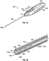
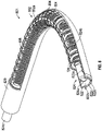
- Delivery shaft 104 is configured to carry a plurality of fasteners 126 and driver 124 (shown in FIG. IB), which can be rotationally driven to deliver fasteners 126 from the distal end 104a of shaft 104.
- Motor 106 enclosed within handle 102 is coupled to driver 124 within delivery shaft 104, to selectively rotate driver either in a forward (e.g., clockwise) direction and reverse (e.g., counterclockwise) direction.
- Control circuit 108 in handle 102 is coupled to motor 106 and to first, e.g., forward control button 110 and second, e.g., reverse control button 112 on handle 102.
- Control circuit 108 governs operation of motor 106 according to pre-programmed operating parameters in response to user commands received by manipulation of buttons 110 and 112.
- multiple helical fasteners 126 are loaded into delivery shaft 104, onto driver 124 from, e.g., cassette 200.
- a user can place distal end 104a of shaft 104 into an exposed staple port 210 in cassette 200 and press reverse control button 112 to signal control circuit 108 to drive motor 106 in a reverse direction to draw fastener 126 out of port 210 and into shaft 104, onto driver 124.
- This process can be repeated multiple times to load a plurality of fasteners 126 into shaft 104.
- the now loaded multi-fire applier 100 is manipulated by a user to dispose distal end 104a of shaft 104 through a surgical incision to access a desired location in a vessel for implantation of one or more fasteners 126.
- multi-fire applier 100 could be preloaded with a full set of fasteners 126 in fastener delivery shaft 104.
- multi-fire applier 100 or another such applier in accordance with this disclosure can be packaged with a fixed or variable set number of fasteners 126 in delivery shaft 104 such that a physician need not load fasteners 126 at the time of surgery.
- the physician could remove multi-fire applier 100 from sterile packaging and start delivering fasteners 126 at desired locations without the need to load applier 100.
- control circuit 108 is pre-programmed to require a two-stage implantation process.
- the first stage commands only a partial implantation of fastener 126.
- the physician is allowed to ascertain whether fastener 126 is placed correctly at the desired location and that the desired located is suitable for implantation of fastener 126.
- the physician is allowed to retract fastener 126 (by pressing the reverse control button 112) and to re-position fastener 126.
- distal end 104a of fastener delivery shaft 104 can be repositioned to additional locations and the physician can repeat the process of delivering additional fasteners 126 at the locations with multi-fire applier 100.
- a plurality of fasteners 126 are provided in cassette 200, to allow easy and accurate loading into multi-fire applier 100.
- base 208 of cassette 200 has a plurality of foil covered spaced apart staple ports or stations 210, each sized to house a fastener 126.
- Deformable cover 212 e.g. a foil cover
- sheath 120 is fabricated from a rigid material.
- the "rigidity" of sheath 120 refers to the ability of sheath 120 to withstand the force applied by a physician to resolve the force of implanting one of fasteners 126.
- sheath 120 may need to be strong enough, e.g., have sufficient column strength to withstand the generally axial resolution force without buckling or being otherwise structurally compromised.
- a variety of biocompatible metals, plastics, or ceramics can be used to fabricate sheath 120, including, e.g., stainless steel, nickel-titanium (Nitinol), etc.
- FIGS. 3A and 3B depict an example of control circuit 108 and an example multi-phased operation of multi-fire applier 100.
- motor 106 is coupled to apply torque to driver 124 of shaft 104.
- Control circuit 108 for motor 106 includes an optical encoder 250 coupled to a counting function 252, to enable counting the revolutions of the battery powered motor 106.
- Control circuit 108 also includes a sensing function 254 that senses the magnitude of current being drawn by motor 106, for deriving torque that motor 106 is encountering when rotating driver 124 to drive fasteners 126.
- Control circuit 108 also includes a comparison function 256 that compares the magnitude of the sensed torque (current) with set torque limits in either the forward or reverse direction, to change the state of operation should excess torque conditions be encountered.
- Control circuit 108 carries embedded code, which expresses pre-programmed rules or algorithms under which different operation states are entered and motor command signals are generated in response to input from the external control sources and the counting, sensing, and comparison functions.
- the pre-programmed rules or algorithms of control circuit 108 are designed to conserve power consumption, placing the circuit into a standby (wait) mode between staple loading and deployment cycles. This makes it possible to power up the staple applier just once and to leave the staple applier on during an entire procedure, avoiding time consumed in repeated power ups and power downs.
- the pre-programmed rules or algorithms of the control circuit also dictate that a desired sequence of steps is faithfully followed in loading, deploying, and reloading the staples, prompting the physician at the initiation of each step and not allowing any short-cuts or deviations along the way.
- Example pre-programmed rules and/or algorithms of a representative control circuit 108 for a multi-fire fastener applier in accordance with this disclosure will now be described in greater detail.
- the pre-programmed rules or algorithms of control circuit 108 enable the optical encoder 250 and drive motor 106 in a forward direction for a set period of time.
- the counting and sensing functions of control circuit 108 count the number of revolutions and sense forward current. If the forward current exceeds a set maximum current level (as determined by the comparison function), the pre-programmed rules or algorithms of control circuit 108 enter a FORWARD TORQUE FATAL state. Otherwise, the sensed forward current is registered by the pre-programmed rules or algorithms of control circuit 108 as a base line for forward torque.
- the pre-programmed rules or algorithms of control circuit 108 enable the optical encoder 250 and counting function 252, and drive motor 106 in a reverse direction for a set period of time.
- the counting function 252 of control circuit 108 counts the number of revolutions, while the sensing function 254 senses reverse current. If the reverse current exceeds a set maximum current level, as determined by the comparison function 256, the pre-programmed rules or algorithms of control circuit 108 enter a REVERSE TORQUE FATAL state. Otherwise, the sensed reverse current is registered by the pre-programmed rules or algorithms of control circuit 108 as a base line for reverse torque.
- the pre-programmed rules or algorithms of control circuit 108 allow the operator to clear the error state one time, e.g., by pressing the forward control button 110. After the error has been cleared, the self-check sequence of the POWER UP state will reinitiate. If during the second self-check sequence, a fatal state is again encountered, the pre-programmed rules or algorithms of control circuit 108 either disable multi-fire applier 100 from use, or again enable the error prompt. In the latter instance, instructions for use can be provided to inform the operator not to use multi-fire applier 100 that has encountered a start-up error twice.
- multi-fire applier 100 After multi-fire applier 100 has been powered up and is in the READY TO LOAD state, the operator is able to load fasteners 126 by initiating a prescribed input command, e.g., by pushing the reverse control button 112. Distal end 104a of fastener delivery shaft 104 can then be inserted into a staple port of the cassette at the time the input command is given.
- a prescribed input command e.g., by pushing the reverse control button 112.
- Distal end 104a of fastener delivery shaft 104 can then be inserted into a staple port of the cassette at the time the input command is given.
- control circuit 108 command motor 106 to rotate in a reverse direction for a set time period and generates a confirmation output with visual indicators (e.g., blinking the reverse green arrow 118).
- Fastener 126 will be drawn from cassette 200 into distal end 104a of fastener delivery shaft 104 of multi-fire applier 100.
- the pre-programmed rules or algorithms of control circuit 108 can include a predetermined number of loading cycles, after which the control presumes multi-fire applier 100 is fully loaded with a proper number of fasteners 126.
- the pre-programmed rules or algorithms of control circuit 108 can then enter a READY TO APPLY state.
- the pre-programmed rules or algorithms of control circuit 108 generate a confirmation output, e.g., audible and visual indicators (e.g., two short beeps and a forward green arrow 116 will blink to prompt the next step, which is to deploy fastener 126.
- the pre-programmed rules or algorithms of control circuit 108 do not accept any command other than the command prescribed for loading (e.g., pushing the reverse control button 112). If an operator provides a contrary command, e.g., by pushing on the forward command button 110, the pre-programmed rules or algorithms of the command circuit 108 can ignore the command. In this way, the pre-programmed rules or algorithms of the command circuit can be configured to require an operator to follow a prescribed sequence in operating the staple applier.
- control circuit 108 only partially deploy fastener 126 and generate a confirmation output, e.g., four beeps and/or alternatively blinking the forward and reverse arrows 116 and 118, prompting the operator to make a choice. This indicates that the operator may chose to continue deployment or to withdraw fastener 126 back into multi-fire applier 100, as described above.
- the pre-programmed rules or algorithms of control circuit 108 can be configured to drive motor 106 in the forward direction for a set number of rotations monitored by the counting function 252, to complete the implantation of fastener 126.
- the pre-programmed rules or algorithms of control circuit 108 generate a confirmation output, e.g., audio and visual indicators.
- the pre-programmed rules or algorithms of control circuit 108 return to the READY TO APPLY state to repeat the deployment procedure to implant a plurality of fasteners 126.
- the pre-programmed rules or algorithms of control circuit 108 can include a predetermined number of delivery cycles for delivering all of fasteners 126 in multi-fire applier 100, after which the control circuit can return to the READY TO LOAD state.
- the pre-programmed rules or algorithms of control circuit 108 can be configured to continue to check battery voltage against a set minimum. The operational states proceed as described as long as the battery voltage exceeds the set minimum. If, during an operational state the battery voltage falls below the set minimum, the pre-programmed rules or algorithms of control circuit 108 can be configured to enter a LOW BATTERY FATAL state.
- audible tones and visual indicators e.g., indicators 114, 116, and 118
- the pre-programmed rules or algorithms of control circuit 108 enter a READY TO APPLY state.
- the operator is ready to deploy fastener 126, the operator is able to deploy fastener 126 by initiating a prescribed input command, e.g., by pressing the forward control button 110.
- the pre-programmed rules or algorithms of control circuit 108 can be configured to drive motor 106 in the forward direction for a set number of rotations monitored by the counting function 252, to complete the implantation of fastener 126.
- the pre-programmed rules or algorithms of control circuit 108 generate a confirmation output, e.g., audio and visual indicators.
- the pre-programmed rules or algorithms of control circuit 108 return to the READY TO APPLY state to repeat the deployment procedure to implant a plurality of fasteners 126.
- the pre-programmed rules or algorithms of control circuit 108 can include a predetermined number of delivery cycles corresponding to the number of fasteners 126 pre-loaded in multi-fire applier 100.
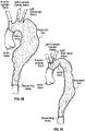
- a healthy aorta the body's largest artery, has a general shape like the handle portion of a walking cane (see FIG. 4 ).
- the short length of the curved handle comes out of the heart and curls through the aortic arch.
- Multiple smaller arteries branch off at the aortic arch to serve the head and arms.
- the aorta continues to descend through the chest cavity into the abdomen and separates to provide blood to the abdominal organs and both legs.
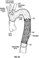
- Various abnormalities may affect the aorta, most of which are considered potentially life-threatening.
- Prevalent aortic abnormalities include aortic aneurysms and aortic dissections, as nonlimiting examples.
- thoracic aortic aneurysm Common causes of a thoracic aortic aneurysm include hardening of the arteries (atherosclerosis), degeneration of the media of the aortic wall, as well as from local hemodynamic forces. Additional risk factors include various connective tissue disorders such as Marfan syndrome, previous dissection of the aorta, and trauma such as falls or motor vehicle accidents. They also sometimes occur in people who have bicuspid aortic valves.
- the endovascular graft 700 serves to exclude a portion of the vascular system from blood flow and blood pressure. In order to obtain exclusion of a portion of the vascular system, the endovascular graft must be sealed against the vascular wall, which requires apposition between the endovascular graft 700 and the vascular wall. The endovascular graft 12 may need to be prevented from moving or migrating from its deployed position within the vascular system.
- FIG. 8 illustrates that the driver 824, fastener cartridge 822, are radially inwardly nested within the sheath 820 such that fastener cartridge 822 is disposed within sheath 820 and the driver 824 is disposed within the cartridge 822 and/or sheath 820.
- An internal assembly 802 is disposed within the sheath 820 proximal of the fastener cartridge 822 and is sized and configured to hold a plurality of fasteners 126 in stacked relationship along the long axis of delivery shaft 801.
- cartridge 822 can comprise only a distal end portion of the applier. Proximal of the cartridge 822 and within the sheath 820 is disposed the internal assembly 802, which is partially illustrated due to the removal of a portion of the sheath 820 in FIG. 8 .
- the assembly 802 includes a first member 802a, a second member 802b (not shown in FIG. 8 but illustrated in FIG. 8A ), hoops 804, and projections 806.
- FIG. 8A illustrates that a first number of cylindrically shaped projections 806 are coupled to the first member 802a and a second number of cylindrically shaped projections 806 are coupled to the second member 802b.
- the projections 806 extend inward toward the driver 824 (in particular intermediate portion 824b) from the first member 802a and the second member 802b ( FIG. 8A ).
- the projections 806 provide a ladder structure that has a pitch corresponding to that of the fasteners 126.
- the projections 806 and spaces 806a in concert with the driver 824 act to feed the fasteners 126 forward toward the distal end of the delivery shaft 801 to fastener cartridge 822.
- the distal end portion of the driver 824 can be of a solid construction.
- the intermediate portion 824b of the driver 824 can be constructed of a braided cable, allowing for greater flexibility in the portion of the delivery shaft 801 that experiences the greatest degree of bending.
- the intermediate portion 824b can connect to a shaft portion 824c of the driver 824 proximal of the internal assembly 802 in some cases.
- the length of the intermediate portion 824b and the assembly 802 can be determined by the number of fasteners 126 to be retained therein.
- FIG. 9 illustrates a distal end portion of another example multi-fire fastener applier in accordance with this disclosure.
- This multi-fire fastener applier can include a construction of some features and components similar to those discussed with reference to the multi-fire fastener appliers discussed with respect to previous FIGURES.
- the multi-fire applier can have a handle that includes a battery powered motor, control circuit, first and second control buttons, indicators and functionality as previously discussed.
- components may be hand actuated.
- applier can be a single use component that is supplied to the user within a package in a sterile condition with the fasteners preloaded therein.
- multi-fire applier can be provided to users in a kit along with other components, including, e.g., a supply of fasteners, and a cassette for holding and enabling the fasteners to be loaded into the applier.
- Helical track 922 extends substantially along a neutral axis of the delivery shaft 901.
- Helical track 922 is coupled to the support member 902.
- the member support 902 provides support to the helical track 922.
- the helical track 922 is adapted to receive multiple fasteners 126 therein and can act as a ladder feature for the advancement of the fasteners 126.
- the helical track 922 has a pitch adapted to correspond with that of the fasteners 126 to allow for passage of the fasteners therealong.
- Helical track 922 includes a neutral axis portion 922a, a first portion 922b, and a third portion 922c.
- the neutral axis portion 922a has a larger cross-sectional area as compared with the first portion 922b and second portion 922c.
- the first portion 922b and the second portion 922c are provided with a smaller cross-sectional area to maintain clearance sufficient to allow passage of the fastener 126 when the fastener delivery shaft 901 is bent.
- the storage member 1008a, 1008b, 1008c, and 1008d are disposed within the sheath 1020 and can be disposed along the intermediate portion 1024b. Although four storage members are illustrated in FIG. 10 , the number of storage features can vary depending upon the number of fasteners 126 desired to be delivered. Each storage member 1008a, 1008b, 1008c, and 1008d can comprise an internal cassette that houses one or more fasteners 126. Each storage member 1008a, 1008b, 1008c, and 1008d can be constructed hollow internal storage volume configured to receive one or more of the fasteners 126. The storage members 1008a, 1008b, 1008c, and 1008d are spaced from one another to allow for flexibility of the delivery shaft 1001.
- the advancing component 1006 is adapted to be moveable relative to the sheath 1020, driver 1024, and storage members 1008a, 1008b, 1008c, and 1008d and can be constructed of a sufficiently rigid but flexible material that allows for bending of the fastener delivery shaft 1001.
- the advancing component 1006 can be utilized to contact and apply a push force to the fasteners 126. This can be achieved because the storage members 1008a, 1008b, 1008c, and 1008d are hollow and are adapted to receive the advancing component 1006 therein.
- the push force exerted by the advancing component 1006 on the fasteners 126 can be sufficient to engage the fasteners 126 with a cantilever barb, hook, or similar transfer feature at a proximal end of each storage member 1008a, 1008b, 1008c, and 1008d. Once the fastener 126 engages the transfer feature, the fastener 126 is able to advance to the next most distal storage member until the fastener cartridge 1022 is reached.
- the advancing component can comprise compressed gas or fluid, a spring, etc.
- the advancing member can be driven by a battery or motor actuated in some instances. In other instances, the movement of the advancing member can be the result of knobs or other features on the fastener applier.
- One or more of the embodiments of the multi-fire fastener applier discussed herein can include a sensor making use of electric resistance or capacitance in the sheath to detect the position of the fasteners within the distal end of the fastener applier.
- the sensor(s) may have a mechanical feature in the sheath that can provide a calibrated resistance to the fasteners during advancement into a start position.
- the fasteners may be detected through torque sensing on the driver and/or other drive components (e.g., drive shaft, etc.)
Landscapes
- Health & Medical Sciences (AREA)
- Life Sciences & Earth Sciences (AREA)
- Surgery (AREA)
- Heart & Thoracic Surgery (AREA)
- Engineering & Computer Science (AREA)
- Biomedical Technology (AREA)
- Nuclear Medicine, Radiotherapy & Molecular Imaging (AREA)
- Medical Informatics (AREA)
- Molecular Biology (AREA)
- Animal Behavior & Ethology (AREA)
- General Health & Medical Sciences (AREA)
- Public Health (AREA)
- Veterinary Medicine (AREA)
- Surgical Instruments (AREA)
- Prostheses (AREA)
Claims (11)
- Prothesenbefestigungsmittelapplizierer (100), umfassend:einen Griff (102), der einen Motor (106) und eine Steuerschaltung (108) enthält;eine Vielzahl von Eingabesteuerungen (110, 112), die mit dem Griff verbunden und mit der Steuerschaltung kommunikativ verbunden ist; undeine Befestigungsmittelzuführungswelle (104), umfassend:ein Befestigungsmittelmagazin (122), umfassend eine Vielzahl von Innengewinden (122a), die konfiguriert ist, um eine Vielzahl von spiralförmigen Befestigungsmitteln (126) in einem gestapelten Verhältnis aufzunehmen;eine Mitnehmerwelle (124), die mit dem Motor wirkverbunden, innerhalb des Befestigungsmittelmagazins eingerichtet und konfiguriert ist, um durch jeweilige innere Durchmesser der spiralförmigen Befestigungsmittel zu führen,wobei die Steuerschaltung konfiguriert ist, um den Motor als Reaktion auf Signale von einer oder mehreren der Eingabesteuerungen zu steuern, um die Mitnehmerwelle zu drehen, um zu bewirken, dass eines oder mehrere der spiralförmigen Befestigungsmittel relativ zu dem Befestigungsmittelmagazin axial vorgeschoben werden,wobei die Befestigungsmittelzuführungswelle ferner eine Vielzahl von zylindrisch geformten Vorsprüngen (806) proximal des Befestigungsmittelmagazins umfasst, wobei die Vielzahl von Vorsprüngen nur entlang einer neutralen Achse der Befestigungsmittelzuführungswelle angeordnet und angepasst ist, um einer Steigung von dem einem oder den mehreren der spiralförmigen Befestigungsmittel zu entsprechen, um eine Aufnahme und einen Durchgang des einen oder der mehreren Befestigungsmittel dort entlang zu ermöglichen.
- Befestigungsmittelapplizierer nach Anspruch 1, wobei ein distales Ende (122b) des Befestigungsmittelmagazins einen gewindefreien Abschnitt beinhaltet.
- Befestigungsmittelapplizierer nach Anspruch 2, wobei das distale Ende des Befestigungsmittelmagazins eine Vielzahl von in Umfangsrichtung eingerichteten, sich axial erstreckenden Zinnen (822c) beinhaltet.
- Befestigungsmittelapplizierer nach Anspruch 1, wobei die Eingabesteuerungen eine Vorwärtstaste und eine Rückwärtstaste beinhalten.
- Befestigungsmittelapplizierer nach Anspruch 1, wobei die Steuerschaltung konfiguriert ist, um den Motor als Reaktion auf Signale von einer oder mehreren der Eingabesteuerungen zu steuern, um die Mitnehmerwelle zu drehen, um eines der spiralförmigen Befestigungsmittel aus einem distalen Ende der Befestigungsmittelzuführungswelle in mehreren Phasen vorzuschieben, die jeweils durch mindestens ein Signal von mindestens einer der Eingabesteuerungen getrennt ist oder ferner umfassend eine Batterie, die innerhalb des Griffs enthalten und konfiguriert ist, um die Steuerschaltung und den Motor anzutreiben.
- Befestigungsmittelapplizierer nach Anspruch 1, wobei die Mitnehmerwelle "D"-geformt ist mit einer ebenen Oberfläche, die mit einer halbkreisförmigen Oberfläche verbunden ist.
- Befestigungsmittelapplizierer nach Anspruch 6, wobei die Mitnehmerwelle derart konfiguriert ist, dass die ebene Oberfläche die jeweiligen Traversen der spiralförmigen Befestigungsmittel in Eingriff nimmt, wobei sich jede Traverse über den gesamten inneren Durchmesser des spiralförmigen Befestigungsmittels hinweg erstreckt.
- Befestigungsmittelapplizierer nach Anspruch 1, wobei ein Abstand zwischen der Vielzahl von Vorsprüngen gleich bleibt, selbst wenn die Befestigungsmittelzuführungswelle während eines Betriebs gebogen wird.
- Befestigungsmittelapplizierer nach Anspruch 1, wobei die Steuerschaltung konfiguriert ist, um den Motor als Reaktion auf Signale von einer oder mehreren der Eingabesteuerungen zu steuern, um die Mitnehmerwelle zu drehen, um zu bewirken, dass das eine oder die mehreren der spiralförmigen Befestigungsmittel relativ entlang der Vielzahl von Vorsprüngen axial vorgeschoben werden.
- Prothesenbefestigungsmittelzuführungssystem, umfassend:einen Befestigungsmittelapplizierer nach einem der Ansprüche 1 bis 9; undeine Vielzahl von spiralförmigen Befestigungsmitteln (126), die in dem gestapelten Verhältnis in den Innengewinden des Befestigungsmittelmagazins aufgenommen wird, wobei die Mitnehmerwelle durch jeweilige Innendurchmesser der spiralförmigen Befestigungsmittel führt.
- Befestigungsmittelzuführungssystem nach Anspruch 10, wobei die Mitnehmerwelle einen flexiblen Zwischenabschnitt, umfassend ein geflochtenes Kabel, beinhaltet.
Applications Claiming Priority (2)
| Application Number | Priority Date | Filing Date | Title |
|---|---|---|---|
| US201361905551P | 2013-11-18 | 2013-11-18 | |
| PCT/US2014/066205 WO2015074066A2 (en) | 2013-11-18 | 2014-11-18 | Multi-fire fastener delivery system and method |
Publications (3)
| Publication Number | Publication Date |
|---|---|
| EP3071123A2 EP3071123A2 (de) | 2016-09-28 |
| EP3071123A4 EP3071123A4 (de) | 2018-05-30 |
| EP3071123B1 true EP3071123B1 (de) | 2022-11-09 |
Family
ID=53058298
Family Applications (1)
| Application Number | Title | Priority Date | Filing Date |
|---|---|---|---|
| EP14862952.0A Active EP3071123B1 (de) | 2013-11-18 | 2014-11-18 | System zur freisetzung von befestigungselementen mit mehrfachauslösung |
Country Status (5)
| Country | Link |
|---|---|
| US (3) | US10524794B2 (de) |
| EP (1) | EP3071123B1 (de) |
| JP (1) | JP6535342B2 (de) |
| CN (1) | CN106028973B (de) |
| WO (1) | WO2015074066A2 (de) |
Families Citing this family (19)
| Publication number | Priority date | Publication date | Assignee | Title |
|---|---|---|---|---|
| US20160262743A1 (en) * | 2015-03-12 | 2016-09-15 | Nir Altman | Tack guide with lumens for articulating members |
| US10786245B2 (en) | 2016-10-04 | 2020-09-29 | Ergosuture Corp. | Rotational driver |
| US10426457B2 (en) * | 2017-02-07 | 2019-10-01 | Apollo Endosurgery Us, Inc. | Surgical fastener deployment system |
| US10772651B2 (en) | 2017-10-30 | 2020-09-15 | Ethicon Llc | Surgical instruments comprising a system for articulation and rotation compensation |
| US11510741B2 (en) | 2017-10-30 | 2022-11-29 | Cilag Gmbh International | Method for producing a surgical instrument comprising a smart electrical system |
| US20190201042A1 (en) | 2017-12-28 | 2019-07-04 | Ethicon Llc | Determining the state of an ultrasonic electromechanical system according to frequency shift |
| US11257589B2 (en) | 2017-12-28 | 2022-02-22 | Cilag Gmbh International | Real-time analysis of comprehensive cost of all instrumentation used in surgery utilizing data fluidity to track instruments through stocking and in-house processes |
| WO2019133144A1 (en) | 2017-12-28 | 2019-07-04 | Ethicon Llc | Detection and escalation of security responses of surgical instruments to increasing severity threats |
| US11464559B2 (en) | 2017-12-28 | 2022-10-11 | Cilag Gmbh International | Estimating state of ultrasonic end effector and control system therefor |
| US11864728B2 (en) | 2017-12-28 | 2024-01-09 | Cilag Gmbh International | Characterization of tissue irregularities through the use of mono-chromatic light refractivity |
| US11076921B2 (en) | 2017-12-28 | 2021-08-03 | Cilag Gmbh International | Adaptive control program updates for surgical hubs |
| US11998193B2 (en) | 2017-12-28 | 2024-06-04 | Cilag Gmbh International | Method for usage of the shroud as an aspect of sensing or controlling a powered surgical device, and a control algorithm to adjust its default operation |
| US12096916B2 (en) | 2017-12-28 | 2024-09-24 | Cilag Gmbh International | Method of sensing particulate from smoke evacuated from a patient, adjusting the pump speed based on the sensed information, and communicating the functional parameters of the system to the hub |
| US11969142B2 (en) | 2017-12-28 | 2024-04-30 | Cilag Gmbh International | Method of compressing tissue within a stapling device and simultaneously displaying the location of the tissue within the jaws |
| US20190206569A1 (en) | 2017-12-28 | 2019-07-04 | Ethicon Llc | Method of cloud based data analytics for use with the hub |
| US12062442B2 (en) | 2017-12-28 | 2024-08-13 | Cilag Gmbh International | Method for operating surgical instrument systems |
| US11337746B2 (en) | 2018-03-08 | 2022-05-24 | Cilag Gmbh International | Smart blade and power pulsing |
| EP3809981A1 (de) | 2018-06-20 | 2021-04-28 | ErgoSuture Corp. | Nadeltreiber für chirurgische nahtinstrumente und herstellungsverfahren |
| KR102126675B1 (ko) * | 2020-04-08 | 2020-06-26 | 이유민 | 복강경용 스태플러 |
Family Cites Families (26)
| Publication number | Priority date | Publication date | Assignee | Title |
|---|---|---|---|---|
| US5433721A (en) * | 1992-01-17 | 1995-07-18 | Ethicon, Inc. | Endoscopic instrument having a torsionally stiff drive shaft for applying fasteners to tissue |
| US5582616A (en) * | 1994-08-05 | 1996-12-10 | Origin Medsystems, Inc. | Surgical helical fastener with applicator |
| US5851212A (en) * | 1997-06-11 | 1998-12-22 | Endius Incorporated | Surgical instrument |
| US8075570B2 (en) * | 2001-11-28 | 2011-12-13 | Aptus Endosystems, Inc. | Intraluminal prosthesis attachment systems and methods |
| JP2002526193A (ja) | 1998-09-18 | 2002-08-20 | ユナイテッド ステイツ サージカル コーポレーション | 脈管内ファスナーアプリケータ |
| AU3827001A (en) * | 2000-02-15 | 2001-08-27 | Eva Corp | Delivery catheter assembly and method of securing a surgical component to a vessel during a surgical procedure |
| US8231639B2 (en) | 2001-11-28 | 2012-07-31 | Aptus Endosystems, Inc. | Systems and methods for attaching a prosthesis within a body lumen or hollow organ |
| US20070073389A1 (en) * | 2001-11-28 | 2007-03-29 | Aptus Endosystems, Inc. | Endovascular aneurysm devices, systems, and methods |
| US7823267B2 (en) * | 2001-11-28 | 2010-11-02 | Aptus Endosystems, Inc. | Devices, systems, and methods for prosthesis delivery and implantation, including the use of a fastener tool |
| US8926637B2 (en) * | 2003-06-13 | 2015-01-06 | Covidien Lp | Multiple member interconnect for surgical instrument and absorbable screw fastener |
| AU2004249161B9 (en) | 2003-06-13 | 2010-04-08 | Covidien Lp | Multiple member interconnect for surgical instrument and absorbable screw fastener |
| WO2008010948A2 (en) * | 2006-07-18 | 2008-01-24 | Davol Inc. | Method and apparatus for surgical fastening |
| US9017345B2 (en) * | 2006-10-06 | 2015-04-28 | Covidien Lp | Coil fastener applier with flexible shaft |
| US20090270976A1 (en) | 2008-04-24 | 2009-10-29 | Medtronic Vascular, Inc. | Stent Graft Fixation System and Method of Use |
| US8087142B2 (en) * | 2008-07-02 | 2012-01-03 | Easylap Ltd. | Pivoting tacker |
| US8444036B2 (en) * | 2009-02-06 | 2013-05-21 | Ethicon Endo-Surgery, Inc. | Motor driven surgical fastener device with mechanisms for adjusting a tissue gap within the end effector |
| US8523881B2 (en) | 2010-07-26 | 2013-09-03 | Valtech Cardio, Ltd. | Multiple anchor delivery tool |
| US8728098B2 (en) * | 2009-05-12 | 2014-05-20 | Ethicon, Inc. | Surgical fasteners, applicator instruments, and methods for deploying surgical fasteners |
| US8920439B2 (en) * | 2009-05-12 | 2014-12-30 | Ethicon, Inc. | Applicator instruments having curved and articulating shafts for deploying surgical fasteners and methods therefor |
| US8579920B2 (en) * | 2009-05-12 | 2013-11-12 | Ethicon, Inc. | Surgical fasteners, applicator instruments, and methods for deploying surgical fasteners |
| US8821514B2 (en) * | 2009-06-08 | 2014-09-02 | Covidien Lp | Powered tack applier |
| US8955732B2 (en) * | 2009-08-11 | 2015-02-17 | Covidien Lp | Surgical stapling apparatus |
| US20110295282A1 (en) * | 2010-05-26 | 2011-12-01 | Tyco Healthcare Group Lp | Fastener and drive method for soft tissue repair |
| ES2613828T3 (es) * | 2011-09-26 | 2017-05-26 | Artack Medical (2013) Ltd. | Dispositivo de sujeción quirúrgica |
| EP2775896B1 (de) * | 2011-11-08 | 2020-01-01 | Valtech Cardio, Ltd. | Gesteuerte lenkfunktionalität für ein implantatabgabewerkzeug |
| US9486213B2 (en) * | 2011-11-14 | 2016-11-08 | Thd Lap Ltd. | Drive mechanism for articulating tacker |
-
2014
- 2014-11-18 US US14/546,766 patent/US10524794B2/en active Active
- 2014-11-18 EP EP14862952.0A patent/EP3071123B1/de active Active
- 2014-11-18 CN CN201480063108.3A patent/CN106028973B/zh active Active
- 2014-11-18 JP JP2016554548A patent/JP6535342B2/ja active Active
- 2014-11-18 WO PCT/US2014/066205 patent/WO2015074066A2/en active Application Filing
-
2019
- 2019-10-24 US US16/663,179 patent/US11589862B2/en active Active
-
2023
- 2023-01-26 US US18/101,696 patent/US20230165583A1/en active Pending
Also Published As
| Publication number | Publication date |
|---|---|
| CN106028973A (zh) | 2016-10-12 |
| JP2016540619A (ja) | 2016-12-28 |
| US20200121319A1 (en) | 2020-04-23 |
| WO2015074066A3 (en) | 2015-10-29 |
| US20150142016A1 (en) | 2015-05-21 |
| CN106028973B (zh) | 2020-07-14 |
| US11589862B2 (en) | 2023-02-28 |
| WO2015074066A2 (en) | 2015-05-21 |
| US10524794B2 (en) | 2020-01-07 |
| JP6535342B2 (ja) | 2019-06-26 |
| EP3071123A4 (de) | 2018-05-30 |
| EP3071123A2 (de) | 2016-09-28 |
| US20230165583A1 (en) | 2023-06-01 |
Similar Documents
| Publication | Publication Date | Title |
|---|---|---|
| US11589862B2 (en) | Multi-fire fastener delivery system and method | |
| US10098770B2 (en) | Endovascular aneurysm devices, systems, and methods | |
| US10194905B2 (en) | Devices, systems, and methods for endovascular staple and/or prosthesis delivery and implantation | |
| US10835404B2 (en) | Delivery system for a retractable outer sheath | |
| US20090112303A1 (en) | Devices, systems, and methods for endovascular staple and/or prosthesis delivery and implantation | |
| US20090138072A1 (en) | Devices, systems, and methods for endovascular staple and/or prosthesis delivery and implantation | |
| US8075570B2 (en) | Intraluminal prosthesis attachment systems and methods | |
| CA2464900C (en) | Intraluminal prosthesis attachment systems and methods | |
| CA2539585C (en) | Catheter-based fastener implantation apparatus and methods with implantation force resolution | |
| US7169172B2 (en) | Method and apparatus for caged stent delivery | |
| EP2349087A1 (de) | Vorrichtungen, systeme und verfahren zur freisetzung einer endovaskulären klammer und/oder prothese sowie implantation | |
| EP2724695B1 (de) | Gestuftes Abgabesystem mit niedrigem Profil | |
| WO2010044854A1 (en) | Devices, systems, and methods for endovascular staple and/or prosthesis delivery and implantation |
Legal Events
| Date | Code | Title | Description |
|---|---|---|---|
| PUAI | Public reference made under article 153(3) epc to a published international application that has entered the european phase |
Free format text: ORIGINAL CODE: 0009012 |
|
| 17P | Request for examination filed |
Effective date: 20160606 |
|
| AK | Designated contracting states |
Kind code of ref document: A2 Designated state(s): AL AT BE BG CH CY CZ DE DK EE ES FI FR GB GR HR HU IE IS IT LI LT LU LV MC MK MT NL NO PL PT RO RS SE SI SK SM TR |
|
| AX | Request for extension of the european patent |
Extension state: BA ME |
|
| DAX | Request for extension of the european patent (deleted) | ||
| RIC1 | Information provided on ipc code assigned before grant |
Ipc: A61B 17/068 20060101AFI20170816BHEP |
|
| REG | Reference to a national code |
Ref country code: DE Ref legal event code: R079 Ref document number: 602014085506 Country of ref document: DE Free format text: PREVIOUS MAIN CLASS: A61B0017115000 Ipc: A61B0017068000 |
|
| A4 | Supplementary search report drawn up and despatched |
Effective date: 20180504 |
|
| RIC1 | Information provided on ipc code assigned before grant |
Ipc: A61B 17/068 20060101AFI20180426BHEP |
|
| STAA | Information on the status of an ep patent application or granted ep patent |
Free format text: STATUS: EXAMINATION IS IN PROGRESS |
|
| 17Q | First examination report despatched |
Effective date: 20200224 |
|
| STAA | Information on the status of an ep patent application or granted ep patent |
Free format text: STATUS: EXAMINATION IS IN PROGRESS |
|
| GRAP | Despatch of communication of intention to grant a patent |
Free format text: ORIGINAL CODE: EPIDOSNIGR1 |
|
| STAA | Information on the status of an ep patent application or granted ep patent |
Free format text: STATUS: GRANT OF PATENT IS INTENDED |
|
| INTG | Intention to grant announced |
Effective date: 20220311 |
|
| GRAJ | Information related to disapproval of communication of intention to grant by the applicant or resumption of examination proceedings by the epo deleted |
Free format text: ORIGINAL CODE: EPIDOSDIGR1 |
|
| STAA | Information on the status of an ep patent application or granted ep patent |
Free format text: STATUS: EXAMINATION IS IN PROGRESS |
|
| GRAP | Despatch of communication of intention to grant a patent |
Free format text: ORIGINAL CODE: EPIDOSNIGR1 |
|
| STAA | Information on the status of an ep patent application or granted ep patent |
Free format text: STATUS: GRANT OF PATENT IS INTENDED |
|
| INTC | Intention to grant announced (deleted) | ||
| INTG | Intention to grant announced |
Effective date: 20220726 |
|
| GRAS | Grant fee paid |
Free format text: ORIGINAL CODE: EPIDOSNIGR3 |
|
| GRAA | (expected) grant |
Free format text: ORIGINAL CODE: 0009210 |
|
| STAA | Information on the status of an ep patent application or granted ep patent |
Free format text: STATUS: THE PATENT HAS BEEN GRANTED |
|
| AK | Designated contracting states |
Kind code of ref document: B1 Designated state(s): AL AT BE BG CH CY CZ DE DK EE ES FI FR GB GR HR HU IE IS IT LI LT LU LV MC MK MT NL NO PL PT RO RS SE SI SK SM TR |
|
| REG | Reference to a national code |
Ref country code: GB Ref legal event code: FG4D |
|
| REG | Reference to a national code |
Ref country code: CH Ref legal event code: EP Ref country code: AT Ref legal event code: REF Ref document number: 1529842 Country of ref document: AT Kind code of ref document: T Effective date: 20221115 |
|
| REG | Reference to a national code |
Ref country code: DE Ref legal event code: R096 Ref document number: 602014085506 Country of ref document: DE |
|
| REG | Reference to a national code |
Ref country code: IE Ref legal event code: FG4D |
|
| REG | Reference to a national code |
Ref country code: LT Ref legal event code: MG9D |
|
| REG | Reference to a national code |
Ref country code: NL Ref legal event code: MP Effective date: 20221109 |
|
| REG | Reference to a national code |
Ref country code: AT Ref legal event code: MK05 Ref document number: 1529842 Country of ref document: AT Kind code of ref document: T Effective date: 20221109 |
|
| PG25 | Lapsed in a contracting state [announced via postgrant information from national office to epo] |
Ref country code: SE Free format text: LAPSE BECAUSE OF FAILURE TO SUBMIT A TRANSLATION OF THE DESCRIPTION OR TO PAY THE FEE WITHIN THE PRESCRIBED TIME-LIMIT Effective date: 20221109 Ref country code: PT Free format text: LAPSE BECAUSE OF FAILURE TO SUBMIT A TRANSLATION OF THE DESCRIPTION OR TO PAY THE FEE WITHIN THE PRESCRIBED TIME-LIMIT Effective date: 20230309 Ref country code: NO Free format text: LAPSE BECAUSE OF FAILURE TO SUBMIT A TRANSLATION OF THE DESCRIPTION OR TO PAY THE FEE WITHIN THE PRESCRIBED TIME-LIMIT Effective date: 20230209 Ref country code: LT Free format text: LAPSE BECAUSE OF FAILURE TO SUBMIT A TRANSLATION OF THE DESCRIPTION OR TO PAY THE FEE WITHIN THE PRESCRIBED TIME-LIMIT Effective date: 20221109 Ref country code: FI Free format text: LAPSE BECAUSE OF FAILURE TO SUBMIT A TRANSLATION OF THE DESCRIPTION OR TO PAY THE FEE WITHIN THE PRESCRIBED TIME-LIMIT Effective date: 20221109 Ref country code: ES Free format text: LAPSE BECAUSE OF FAILURE TO SUBMIT A TRANSLATION OF THE DESCRIPTION OR TO PAY THE FEE WITHIN THE PRESCRIBED TIME-LIMIT Effective date: 20221109 Ref country code: AT Free format text: LAPSE BECAUSE OF FAILURE TO SUBMIT A TRANSLATION OF THE DESCRIPTION OR TO PAY THE FEE WITHIN THE PRESCRIBED TIME-LIMIT Effective date: 20221109 |
|
| PG25 | Lapsed in a contracting state [announced via postgrant information from national office to epo] |
Ref country code: RS Free format text: LAPSE BECAUSE OF FAILURE TO SUBMIT A TRANSLATION OF THE DESCRIPTION OR TO PAY THE FEE WITHIN THE PRESCRIBED TIME-LIMIT Effective date: 20221109 Ref country code: PL Free format text: LAPSE BECAUSE OF FAILURE TO SUBMIT A TRANSLATION OF THE DESCRIPTION OR TO PAY THE FEE WITHIN THE PRESCRIBED TIME-LIMIT Effective date: 20221109 Ref country code: LV Free format text: LAPSE BECAUSE OF FAILURE TO SUBMIT A TRANSLATION OF THE DESCRIPTION OR TO PAY THE FEE WITHIN THE PRESCRIBED TIME-LIMIT Effective date: 20221109 Ref country code: IS Free format text: LAPSE BECAUSE OF FAILURE TO SUBMIT A TRANSLATION OF THE DESCRIPTION OR TO PAY THE FEE WITHIN THE PRESCRIBED TIME-LIMIT Effective date: 20230309 Ref country code: HR Free format text: LAPSE BECAUSE OF FAILURE TO SUBMIT A TRANSLATION OF THE DESCRIPTION OR TO PAY THE FEE WITHIN THE PRESCRIBED TIME-LIMIT Effective date: 20221109 Ref country code: GR Free format text: LAPSE BECAUSE OF FAILURE TO SUBMIT A TRANSLATION OF THE DESCRIPTION OR TO PAY THE FEE WITHIN THE PRESCRIBED TIME-LIMIT Effective date: 20230210 |
|
| PG25 | Lapsed in a contracting state [announced via postgrant information from national office to epo] |
Ref country code: NL Free format text: LAPSE BECAUSE OF FAILURE TO SUBMIT A TRANSLATION OF THE DESCRIPTION OR TO PAY THE FEE WITHIN THE PRESCRIBED TIME-LIMIT Effective date: 20221109 |
|
| REG | Reference to a national code |
Ref country code: CH Ref legal event code: PL |
|
| REG | Reference to a national code |
Ref country code: BE Ref legal event code: MM Effective date: 20221130 |
|
| PG25 | Lapsed in a contracting state [announced via postgrant information from national office to epo] |
Ref country code: SM Free format text: LAPSE BECAUSE OF FAILURE TO SUBMIT A TRANSLATION OF THE DESCRIPTION OR TO PAY THE FEE WITHIN THE PRESCRIBED TIME-LIMIT Effective date: 20221109 Ref country code: RO Free format text: LAPSE BECAUSE OF FAILURE TO SUBMIT A TRANSLATION OF THE DESCRIPTION OR TO PAY THE FEE WITHIN THE PRESCRIBED TIME-LIMIT Effective date: 20221109 Ref country code: LI Free format text: LAPSE BECAUSE OF NON-PAYMENT OF DUE FEES Effective date: 20221130 Ref country code: EE Free format text: LAPSE BECAUSE OF FAILURE TO SUBMIT A TRANSLATION OF THE DESCRIPTION OR TO PAY THE FEE WITHIN THE PRESCRIBED TIME-LIMIT Effective date: 20221109 Ref country code: DK Free format text: LAPSE BECAUSE OF FAILURE TO SUBMIT A TRANSLATION OF THE DESCRIPTION OR TO PAY THE FEE WITHIN THE PRESCRIBED TIME-LIMIT Effective date: 20221109 Ref country code: CZ Free format text: LAPSE BECAUSE OF FAILURE TO SUBMIT A TRANSLATION OF THE DESCRIPTION OR TO PAY THE FEE WITHIN THE PRESCRIBED TIME-LIMIT Effective date: 20221109 Ref country code: CH Free format text: LAPSE BECAUSE OF NON-PAYMENT OF DUE FEES Effective date: 20221130 |
|
| REG | Reference to a national code |
Ref country code: DE Ref legal event code: R097 Ref document number: 602014085506 Country of ref document: DE |
|
| PG25 | Lapsed in a contracting state [announced via postgrant information from national office to epo] |
Ref country code: SK Free format text: LAPSE BECAUSE OF FAILURE TO SUBMIT A TRANSLATION OF THE DESCRIPTION OR TO PAY THE FEE WITHIN THE PRESCRIBED TIME-LIMIT Effective date: 20221109 Ref country code: LU Free format text: LAPSE BECAUSE OF NON-PAYMENT OF DUE FEES Effective date: 20221118 Ref country code: AL Free format text: LAPSE BECAUSE OF FAILURE TO SUBMIT A TRANSLATION OF THE DESCRIPTION OR TO PAY THE FEE WITHIN THE PRESCRIBED TIME-LIMIT Effective date: 20221109 |
|
| PLBE | No opposition filed within time limit |
Free format text: ORIGINAL CODE: 0009261 |
|
| STAA | Information on the status of an ep patent application or granted ep patent |
Free format text: STATUS: NO OPPOSITION FILED WITHIN TIME LIMIT |
|
| 26N | No opposition filed |
Effective date: 20230810 |
|
| GBPC | Gb: european patent ceased through non-payment of renewal fee |
Effective date: 20230209 |
|
| PG25 | Lapsed in a contracting state [announced via postgrant information from national office to epo] |
Ref country code: SI Free format text: LAPSE BECAUSE OF FAILURE TO SUBMIT A TRANSLATION OF THE DESCRIPTION OR TO PAY THE FEE WITHIN THE PRESCRIBED TIME-LIMIT Effective date: 20221109 Ref country code: BE Free format text: LAPSE BECAUSE OF NON-PAYMENT OF DUE FEES Effective date: 20221130 |
|
| PG25 | Lapsed in a contracting state [announced via postgrant information from national office to epo] |
Ref country code: GB Free format text: LAPSE BECAUSE OF NON-PAYMENT OF DUE FEES Effective date: 20230209 |
|
| PG25 | Lapsed in a contracting state [announced via postgrant information from national office to epo] |
Ref country code: GB Free format text: LAPSE BECAUSE OF NON-PAYMENT OF DUE FEES Effective date: 20230209 |
|
| PG25 | Lapsed in a contracting state [announced via postgrant information from national office to epo] |
Ref country code: HU Free format text: LAPSE BECAUSE OF FAILURE TO SUBMIT A TRANSLATION OF THE DESCRIPTION OR TO PAY THE FEE WITHIN THE PRESCRIBED TIME-LIMIT; INVALID AB INITIO Effective date: 20141118 |
|
| PG25 | Lapsed in a contracting state [announced via postgrant information from national office to epo] |
Ref country code: CY Free format text: LAPSE BECAUSE OF FAILURE TO SUBMIT A TRANSLATION OF THE DESCRIPTION OR TO PAY THE FEE WITHIN THE PRESCRIBED TIME-LIMIT Effective date: 20221109 |
|
| PG25 | Lapsed in a contracting state [announced via postgrant information from national office to epo] |
Ref country code: MK Free format text: LAPSE BECAUSE OF FAILURE TO SUBMIT A TRANSLATION OF THE DESCRIPTION OR TO PAY THE FEE WITHIN THE PRESCRIBED TIME-LIMIT Effective date: 20221109 Ref country code: IT Free format text: LAPSE BECAUSE OF FAILURE TO SUBMIT A TRANSLATION OF THE DESCRIPTION OR TO PAY THE FEE WITHIN THE PRESCRIBED TIME-LIMIT Effective date: 20221109 |
|
| PG25 | Lapsed in a contracting state [announced via postgrant information from national office to epo] |
Ref country code: MC Free format text: LAPSE BECAUSE OF FAILURE TO SUBMIT A TRANSLATION OF THE DESCRIPTION OR TO PAY THE FEE WITHIN THE PRESCRIBED TIME-LIMIT Effective date: 20221109 |
|
| PG25 | Lapsed in a contracting state [announced via postgrant information from national office to epo] |
Ref country code: MC Free format text: LAPSE BECAUSE OF FAILURE TO SUBMIT A TRANSLATION OF THE DESCRIPTION OR TO PAY THE FEE WITHIN THE PRESCRIBED TIME-LIMIT Effective date: 20221109 |
|
| PG25 | Lapsed in a contracting state [announced via postgrant information from national office to epo] |
Ref country code: BG Free format text: LAPSE BECAUSE OF FAILURE TO SUBMIT A TRANSLATION OF THE DESCRIPTION OR TO PAY THE FEE WITHIN THE PRESCRIBED TIME-LIMIT Effective date: 20221109 |
|
| PG25 | Lapsed in a contracting state [announced via postgrant information from national office to epo] |
Ref country code: MT Free format text: LAPSE BECAUSE OF FAILURE TO SUBMIT A TRANSLATION OF THE DESCRIPTION OR TO PAY THE FEE WITHIN THE PRESCRIBED TIME-LIMIT Effective date: 20221109 |
|
| PGFP | Annual fee paid to national office [announced via postgrant information from national office to epo] |
Ref country code: DE Payment date: 20241022 Year of fee payment: 11 |
|
| PGFP | Annual fee paid to national office [announced via postgrant information from national office to epo] |
Ref country code: FR Payment date: 20241022 Year of fee payment: 11 |
|
| PGFP | Annual fee paid to national office [announced via postgrant information from national office to epo] |
Ref country code: IE Payment date: 20241023 Year of fee payment: 11 |