EP3070525A1 - Optical device - Google Patents
Optical device Download PDFInfo
- Publication number
- EP3070525A1 EP3070525A1 EP15197987.9A EP15197987A EP3070525A1 EP 3070525 A1 EP3070525 A1 EP 3070525A1 EP 15197987 A EP15197987 A EP 15197987A EP 3070525 A1 EP3070525 A1 EP 3070525A1
- Authority
- EP
- European Patent Office
- Prior art keywords
- light
- fluorescent wheel
- lens unit
- light source
- fluorescent
- Prior art date
- Legal status (The legal status is an assumption and is not a legal conclusion. Google has not performed a legal analysis and makes no representation as to the accuracy of the status listed.)
- Granted
Links
Images



Classifications
-
- G—PHYSICS
- G03—PHOTOGRAPHY; CINEMATOGRAPHY; ANALOGOUS TECHNIQUES USING WAVES OTHER THAN OPTICAL WAVES; ELECTROGRAPHY; HOLOGRAPHY
- G03B—APPARATUS OR ARRANGEMENTS FOR TAKING PHOTOGRAPHS OR FOR PROJECTING OR VIEWING THEM; APPARATUS OR ARRANGEMENTS EMPLOYING ANALOGOUS TECHNIQUES USING WAVES OTHER THAN OPTICAL WAVES; ACCESSORIES THEREFOR
- G03B21/00—Projectors or projection-type viewers; Accessories therefor
- G03B21/14—Details
- G03B21/20—Lamp housings
- G03B21/2006—Lamp housings characterised by the light source
- G03B21/2033—LED or laser light sources
- G03B21/204—LED or laser light sources using secondary light emission, e.g. luminescence or fluorescence
-
- F—MECHANICAL ENGINEERING; LIGHTING; HEATING; WEAPONS; BLASTING
- F21—LIGHTING
- F21V—FUNCTIONAL FEATURES OR DETAILS OF LIGHTING DEVICES OR SYSTEMS THEREOF; STRUCTURAL COMBINATIONS OF LIGHTING DEVICES WITH OTHER ARTICLES, NOT OTHERWISE PROVIDED FOR
- F21V13/00—Producing particular characteristics or distribution of the light emitted by means of a combination of elements specified in two or more of main groups F21V1/00 - F21V11/00
- F21V13/12—Combinations of only three kinds of elements
- F21V13/14—Combinations of only three kinds of elements the elements being filters or photoluminescent elements, reflectors and refractors
-
- F—MECHANICAL ENGINEERING; LIGHTING; HEATING; WEAPONS; BLASTING
- F21—LIGHTING
- F21V—FUNCTIONAL FEATURES OR DETAILS OF LIGHTING DEVICES OR SYSTEMS THEREOF; STRUCTURAL COMBINATIONS OF LIGHTING DEVICES WITH OTHER ARTICLES, NOT OTHERWISE PROVIDED FOR
- F21V14/00—Controlling the distribution of the light emitted by adjustment of elements
- F21V14/08—Controlling the distribution of the light emitted by adjustment of elements by movement of the screens or filters
-
- G—PHYSICS
- G03—PHOTOGRAPHY; CINEMATOGRAPHY; ANALOGOUS TECHNIQUES USING WAVES OTHER THAN OPTICAL WAVES; ELECTROGRAPHY; HOLOGRAPHY
- G03B—APPARATUS OR ARRANGEMENTS FOR TAKING PHOTOGRAPHS OR FOR PROJECTING OR VIEWING THEM; APPARATUS OR ARRANGEMENTS EMPLOYING ANALOGOUS TECHNIQUES USING WAVES OTHER THAN OPTICAL WAVES; ACCESSORIES THEREFOR
- G03B33/00—Colour photography, other than mere exposure or projection of a colour film
-
- G—PHYSICS
- G03—PHOTOGRAPHY; CINEMATOGRAPHY; ANALOGOUS TECHNIQUES USING WAVES OTHER THAN OPTICAL WAVES; ELECTROGRAPHY; HOLOGRAPHY
- G03B—APPARATUS OR ARRANGEMENTS FOR TAKING PHOTOGRAPHS OR FOR PROJECTING OR VIEWING THEM; APPARATUS OR ARRANGEMENTS EMPLOYING ANALOGOUS TECHNIQUES USING WAVES OTHER THAN OPTICAL WAVES; ACCESSORIES THEREFOR
- G03B21/00—Projectors or projection-type viewers; Accessories therefor
- G03B21/14—Details
- G03B21/16—Cooling; Preventing overheating
-
- H—ELECTRICITY
- H04—ELECTRIC COMMUNICATION TECHNIQUE
- H04N—PICTORIAL COMMUNICATION, e.g. TELEVISION
- H04N9/00—Details of colour television systems
- H04N9/12—Picture reproducers
- H04N9/31—Projection devices for colour picture display, e.g. using electronic spatial light modulators [ESLM]
- H04N9/3141—Constructional details thereof
- H04N9/315—Modulator illumination systems
- H04N9/3158—Modulator illumination systems for controlling the spectrum
Definitions
- the present invention relates to an optical device, and in particular to a projector.
- a projector utilizes a laser source (commonly a blue light lase source) and a fluorescent element to provide projection light.
- a thermal decay may decrease the induction efficiency of the fluorescent element.
- the inducing efficiency decrease often occurs on single-chip digital light processing optical devices and three-chip digital light processing optical devices. Therefore, improving the heat dissipation and luminous efficiency of the fluorescent element is an important issue of the solid-state lighting technology.
- An optical device comprises a fluorescent wheel, a first light source engine and a second light source engine.
- the fluorescent wheel includes a fluorescent powder area (an area including a fluorescent powder).
- the first light source engine provides a first light beam, wherein the first light beam forms a first light spot on the fluorescent powder area of the fluorescent wheel.
- the second light source engine provides a second light beam, wherein the second light beam forms a second light spot on the fluorescent powder area of the fluorescent wheel, and the first light spot is separated from the second light spot.
- a first straight line passes through the center of the fluorescent wheel and the first light spot
- a second straight line passes through the center of the fluorescent wheel and the second light spot
- an included angle between the first straight line and the second straight line is between 45 and 180 degrees.
- a first distance is formed between the first light spot and the center of the fluorescent wheel
- a second distance is formed between the second light spot and the center of the fluorescent wheel
- the first distance differs from the second distance
- the fluorescent wheel comprises a first transparent portion and a second transparent portion.
- the first transparent portion corresponds to the first light source engine
- the second transparent portion corresponds to the second light source engine
- the first light beam passes through the first transparent portion
- the second light beam passes through the second transparent portion.
- the first light source engine is independent from the second light source engine.
- the first light source engine comprises a first light source, a first lens unit and a first dichroic mirror.
- the first light beam travels from the first light source, passing through a first lens group of the first lens unit, the first dichroic mirror, a second lens group of the first lens unit, the first transparent portion or the second transparent portion of the fluorescent wheel, a third lens group of the first lens unit, and a fourth lens group of the first lens unit to be output.
- the first light beam travels from the first light source, passing through the first lens group of the first lens unit, the first dichroic mirror, the second lens group of the first lens unit to the fluorescent wheel, and fluorescent powder in the fluorescent powder area of the fluorescent wheel is induced by the first light beam and generates a first induced light, and the first induced light travels from the fluorescent wheel, passing through second lens group of the first lens unit, reflected by the first dichroic mirror and passing through the fourth lens group of the first lens unit to be output.
- the second light source engine comprises a second light source, a second lens unit and a second dichroic mirror.
- the second light beam travels from the second light source, passing through a fifth lens group of the second lens unit, the second dichroic mirror, a sixth lens group of the second lens unit, the first transparent portion or the second transparent portion of the fluorescent wheel, a seventh lens group of the second lens unit, and an eighth lens group of the second lens unit to be output.
- the second light beam travels from the second light source, passing through the fifth lens group of the second lens unit, the second dichroic mirror, the sixth lens group of the second lens unit to the fluorescent wheel, and the fluorescent powder in the fluorescent powder area of the fluorescent wheel is induced by the second light beam and generates a second induced light, and the second induced light travels from the fluorescent wheel, passing through sixth lens group of the second lens unit, reflected by the second dichroic mirror and passing through the eighth lens group of the second lens unit to be output.
- the first light source engine comprises a first sub light source, a second sub light source, a first lens unit and a first dichroic mirror.
- the first light beam travels from the first sub light source, passing a portion of the first lens unit, the first dichroic mirror to the fluorescent wheel, fluorescent powder in the fluorescent powder area of the fluorescent wheel is induced by the first light beam to generate a first induced light, and the first induced light travels from the fluorescent wheel, passing through a portion of the first lens unit, and reflected by the first dichroic mirror to be output, and a third light beam travels from the second light source, passing a portion of the first lens unit and the first dichroic mirror to be output.
- the second light source engine comprises a third sub light source, a fourth sub light source, a second lens unit and a second dichroic mirror.
- the second light beam travels from the third sub light source, passing a portion of the second lens unit, the second dichroic mirror to the fluorescent wheel, the fluorescent powder in the fluorescent powder area of the fluorescent wheel is induced by the second light beam to generate a second induced light, and the second induced light travels from the fluorescent wheel, passing through a portion of the second lens unit, and reflected by the second dichroic mirror to be output, and a fourth light beam travels from the fourth light source, passing a portion of the second lens unit and the second dichroic mirror to be output.
- the first light source engine comprises a first light source, a first lens unit and a first reflector.
- the first light beam travels from the first light source, passing through a portion of the first lens unit and the fluorescent wheel, a portion of the first light beam directly passing through the fluorescent wheel, fluorescent powder in the fluorescent powder area of the fluorescent wheel is induced by the other portion of the first light beam to generate a first induced light, and the first induced light passes through the fluorescent wheel, and both the first induced light and the portion of the first light beam directly passing through the fluorescent wheel are reflected by the first reflector to be output.
- the second light source engine comprises a second light source, a second lens unit and a second reflector.
- the second light beam travels from the second light source, passing through a portion of the second lens unit and the fluorescent wheel, a portion of the second light beam directly passing through the fluorescent wheel, the fluorescent powder in the fluorescent powder area of the fluorescent wheel is induced by the other portion of the second light beam to generate a second induced light, and the second induced light passes through the fluorescent wheel, and both the second induced light and the portion of the second light beam directly passing through the fluorescent wheel are reflected by the second reflector to be output.
- the fluorescent powder area of the fluorescent wheel comprises a first section, a second section and a third section, a color of the first section differs from a color of the second section, a color of the third section differs from the color of the first section, and the first section, the second section and the third section are arranged along the circumference of the fluorescent wheel.
- the first light spot is separated from the second light spot to decrease the power of single one light spot, and the heat accumulation is therefore decreased.
- the heat accumulation cannot be improved even if the first light spot is separated from the second light spot.
- the applicant found that the heat accumulation can be markedly improved by separating the first light spot from the second light spot.
- the phase angle between the first light spot and the second light spot is between 45 and 180 degrees (180 degrees being preferred)
- the heat accumulation is decreased, thermal decay is prevented, and the inducing efficiency of the fluorescent element is maintained.
- the power of the first light spot is 95W
- the power of the second light spot is 95W.
- the temperature of the fluorescent wheel of the embodiment of the disclosure is decreased to 160°C from 190°C, and the illumination of the embodiment of the disclosure is increased from 4% to 5%.
- a first straight line S1 passes through the center C of the fluorescent wheel 10 and the first light spot 11.
- a second straight line S2 passes through the center C of the fluorescent wheel 10 and the second light spot 12.
- An included angle ⁇ between the first straight line S1 and the second straight line S2 is between 45 and 180 degrees. In this embodiment, the included angle ⁇ between the first straight line S1 and the second straight line S2 is 180 degrees. In another embodiment, the included angle ⁇ between the first straight line S1 and the second straight line S2 can be 45 degrees.
- the first light spot is separated from the second light spot to decrease the power of single one light spot, and the heat accumulation is therefore decreased.
- the heat accumulation cannot be decreased even if the first light spot is separated from the second light spot.
- the applicant found that the heat accumulation can be markedly decreased by separating the first light spot from the second light spot.
- the phase angle between the first light spot and the second light spot is between 45 and 180 degrees (180 degrees being preferred)
- the heat accumulation is decreased, thermal decay is prevented, and the inducing efficiency of the fluorescent element is maintained.
- the power of the first light spot 11 is 95W
- the power of the second light spot 12 is 95W.
- the temperature of the fluorescent wheel of the embodiment of the disclosure is only 160°C the conventional design is 190°C, and the illumination of the embodiment of the disclosure can be increased 4% to 5%.
- the distance between the first light spot and the center of the fluorescent wheel equals the distance between the second light spot and the center of the fluorescent wheel.
- a first distance d1 is formed between the first light spot 11 and the center C of the fluorescent wheel 10.
- a second distance d2 is formed between the second light spot 12 and the center C of the fluorescent wheel 10.
- the first distance d1 differs from the second distance d2.
- the heat accumulation is further decreased by the difference between the first distance d1 and the second distance d2.
- the power of the first light source engine can be different from the power of the second light source engine to make the temperature of the fluorescent wheel 10 uniform.
- the fluorescent wheel 10 comprises a first transparent portion 13 and a second transparent portion 14.
- the first transparent portion 13 corresponds to the first light source engine 100
- the second transparent portion 14 corresponds to the second light source engine 200.
- the first light beam 110 passes through the first transparent portion 13, and the second light beam 210 passes through the second transparent portion 14.
- the fluorescent wheel 10 rotates continuously. Therefore, when the second transparent portion 14 corresponds to the first light source engine 100, the first transparent portion 13 corresponds to the second light source engine 200.
- the first light beam 110 passes through the second transparent portion 14, and the second light beam 210 passes through the first transparent portion 13.
- the transparent portions can be empty notches or made of transparent material, such as transparent glass.
- the first light source engine is independent from the second light source engine.
- Fig. 1 shows an embodiment of single-chip digital light processing optical device.
- the first light source engine comprises a first light source 120, a first lens unit (L1 ⁇ L10) and a first dichroic mirror 130.
- the first light beam 110 travels from the first light source 120, and passes through a first lens group (L1, L2) of the first lens unit, the first dichroic mirror 130, a second lens group (L3, L4) of the first lens unit, the fluorescent wheel 10, a third lens group (L5, L6, L7, L8, L9) of the first lens unit, and a fourth lens group (L10) of the first lens unit to be output (in one embodiment, a blue light is output, wherein the first light beam 110 passes through the first transparent portion 13 and the second transparent portion 14 of the rotating fluorescent wheel 10).
- the first light beam 110 travels from the first light source 120, passing through the first lens group (L1, L2) of the first lens unit, the first dichroic mirror 130, the second lens group (L3, L4) of the first lens unit to the fluorescent wheel 10, then the light spot 11 is located in the fluorescent powder area 15.
- the fluorescent powder in the fluorescent powder area 15 of the fluorescent wheel 10 is induced by the first light beam 110 and generates a first induced light 111 (in one embodiment, the first induced light is red light and green light).
- the first induced light 111 travels from the fluorescent wheel 10, passing through the second lens group (L4, L3) of the first lens unit, reflected by the first dichroic mirror 130 and passing through the fourth lens group (L10) of the first lens unit to be output.
- the second light source engine comprises a second light source 220, a second lens unit (L21 ⁇ L30) and a second dichroic mirror 230.
- the second light beam 210 travels from the second light source 220, passing through a fifth lens group (L21, L22) of the second lens unit, the second dichroic mirror 230, a sixth lens group (L23, L24) of the second lens unit, the fluorescent wheel 10, a seventh lens group (L25, L26, L27, L28, L29) of the second lens unit, and an eighth lens group (L30) of the second lens unit to be output (in one embodiment, a blue light is output, wherein the first light beam 110 passes through the first transparent portion 13 and the second transparent portion 14 of the rotating fluorescent wheel 10).
- the second light beam 210 travels from the second light source 220, passing through the fifth lens group (L21, L22) of the second lens unit, the second dichroic mirror 230, the sixth lens group (L23, L24) of the second lens unit to the fluorescent wheel 10, then the light spot 12 is located in the fluorescent powder area 15.
- the fluorescent powder in the fluorescent powder area 15 of the fluorescent wheel 10 is induced by the second light beam 210 and generates a second induced light 211 (in one embodiment, the second induced light is red light and green light).
- the second induced light 211 travels from the fluorescent wheel 10, passing through sixth lens group (L24, L23) of the second lens unit, reflected by the second dichroic mirror 230 and passing through the eighth lens group (L30) of the second lens unit to be output.
- the embodiment above shows a single-chip digital light processing optical device. However, the embodiment is not meant to restrict the disclosure.
- Fig. 4A shows a three-chip digital light processing optical device 2. In the embodiment of Fig. 4A , the elements with similar functions follow the labels of the embodiment of Fig. 1 .
- the first light source engine 100 comprises a first sub light source 121, a second sub light source 122, a first lens unit (L1 ⁇ L4) and a first dichroic mirror 130.
- the first light beam 110 (in one embodiment, the first light beam is blue light) travels from the first sub light source 121, passing the first lens group (L1) of the first lens unit, the first dichroic mirror 130, and the third lens group (L3) of the first lens unit to the fluorescent wheel 10, the fluorescent powder in the fluorescent powder area 15 of the fluorescent wheel 10 is induced by the first light beam 110 to generate a first induced light 111 (in one embodiment, the first induced light is red light and green light).
- the first induced light 111 travels from the fluorescent wheel 10, passing through the third lens group (L3) of the first lens unit, and reflected by the first dichroic mirror 130 to be output through the fourth lens group (L4) of the first lens unit.
- a third light beam 113 travels from the second light source 122, passing the second lens group (L2) of the first lens unit and the first dichroic mirror 130 to be output through the fourth lens group (L4) of the first lens unit (in one embodiment, the third light beam is blue light).
- the second light source engine 200 comprises a third sub light source 221, a fourth sub light source 222, a second lens unit (L21 ⁇ L24) and a second dichroic mirror 230.
- the second light beam 210 (in one embodiment, the second light beam is blue light) travels from the third sub light source 221, passing the fifth lens group (L21) of the second lens unit, the second dichroic mirror 230 and the seventh lens group (L23) to the fluorescent wheel 10.
- the fluorescent powder in the fluorescent powder area 15 of the fluorescent wheel 10 is induced by the second light beam 210 to generate a second induced light 211 (in one embodiment, the second induced light is red light and blue light), and the second induced light 211 travels from the fluorescent wheel 10, passing through the seventh lens group (L23) of the second lens unit, and reflected by the second dichroic mirror 230 to be output through the eighth lens group (L24) of the second lens unit.
- a fourth light beam 213 travels from the fourth light source 222, passing the sixth lens group (L22) of the second lens unit and the second dichroic mirror 230 to be output through the eighth lens group (L24) of the second lens unit (in one embodiment, the fourth light beam is blue light).
- the fluorescent wheel 10 has no transparent portion.
- a transmissive fluorescent wheel is utilizes.
- the first light source engine 100 of the optical device 3 comprises a first light source 120, a first lens unit (L1 ⁇ L3) and a first reflector 140.
- the first light beam 110 (in this embodiment, the first light beam is blue light) travels from the first light source 120, passing through the first lens group (L1) of the first lens unit and the fluorescent wheel 10, the second lens group (L2) of the first lens unit, the first reflector 140 and the third lens group (L3) of the first lens unit to be output.
- a plurality of gaps are formed within the fluorescent powder in the fluorescent powder area 15 of the fluorescent wheel 10.
- the second light source engine 200 comprises a second light source 220, a second lens unit (L21 ⁇ L23) and a second reflector 240.
- the second light beam 210 (in this embodiment, the second light beam is blue light) travels from the second light source 220, passing through the fourth lens group (L21) of the second lens unit, the fluorescent wheel, the fifth lens group (L22) of the second lens unit, the second reflector 240 and the six lens group (L23) of the second lens unit to be output.
- a plurality of gaps are formed within the fluorescent powder in the fluorescent powder area 15 of the fluorescent wheel 10. Therefore, a portion of the second light beam 210 directly passing through the fluorescent wheel 10 via the gaps, and the fluorescent powder in the fluorescent powder area 15 of the fluorescent wheel is induced by the other portion of the second light beam 210 to generate a second induced light (in this embodiment, the second induced light is red light and green light).
- the second induced light passes through the fluorescent wheel 10 (the second induced light and the portion of the second light beam directly passing through the fluorescent wheel are presented by a second combination light 214).
- the second combination light 214 is reflected by the second reflector 240 to be output.
- Figs. 5B and 5C show the fluorescent wheel 10 of the embodiment of Fig. 5A , wherein the fluorescent wheel 10 has no transparent portion.
- the fluorescent wheel 10 comprises a transmissive substrate 17, a spectral coating layer 16 and a fluorescent agents coating layer 18.
- the transmissive substrate 17 is made of glass.
- the spectral coating layer 16 allows a blue light to pass through and reflects a yellow light.
- Figs. 6A and 6B show another embodiment of the disclosure, wherein the fluorescent wheel 10 has a first transparent portion 13 and a second transparent portion 14.
- the fluorescent powder area of the fluorescent wheel 10 comprises a first section (green fluorescent powder) A1, a second section (yellow fluorescent powder) A2 and a third section (yellow fluorescent powder) A3.
- the color of the first section A1 differs from the color of the second section A2.
- the color of the third section A3 differs from the color of the first section A1.
- the first section A1, the second section A2 and the third section A3 are arranged along the circumference of the fluorescent wheel.
- the color of the second section A2 is the same as the color of the third section A3, however, the disclosure is not meant to restrict the disclosure.
- a first distance is formed between the first light spot 11 and the center C of the fluorescent wheel 10.
- a second distance is formed between the second light spot 12 and the center C of the fluorescent wheel 10.
- the first distance can be the same as the second distance ( Fig. 6A ). In another embodiment, the first distance can be different from the second distance ( Fig. 6B ).
- the colors of the first section, the second section and the third section can be modified in other embodiments.
Landscapes
- Physics & Mathematics (AREA)
- Engineering & Computer Science (AREA)
- General Physics & Mathematics (AREA)
- General Engineering & Computer Science (AREA)
- Multimedia (AREA)
- Optics & Photonics (AREA)
- Projection Apparatus (AREA)
- Spectroscopy & Molecular Physics (AREA)
- Non-Portable Lighting Devices Or Systems Thereof (AREA)
Abstract
Description
- This application claims the benefit of
U.S. Provisional Application No. 62/136,126, filed Mar. 20, 2015 - The present invention relates to an optical device, and in particular to a projector.
- Conventionally, a projector utilizes a laser source (commonly a blue light lase source) and a fluorescent element to provide projection light. However, after a long-term use, a thermal decay may decrease the induction efficiency of the fluorescent element. The inducing efficiency decrease often occurs on single-chip digital light processing optical devices and three-chip digital light processing optical devices. Therefore, improving the heat dissipation and luminous efficiency of the fluorescent element is an important issue of the solid-state lighting technology.
- It is an object of the present invention to provide an enhance optical device, particularly an enhanced optical projector, suited to at least partially overcoming the above drawings, particularly for accomplishing an enhanced heat dissipation and luminous efficiency of the fluorescent element used therein.
- This problem is solved by an optical device, particularly by an optical projector, according to
claim 1. Further advantageous embodiments are the subject-matter of the dependent claims. - An optical device according to the present invention comprises a fluorescent wheel, a first light source engine and a second light source engine. The fluorescent wheel includes a fluorescent powder area (an area including a fluorescent powder). The first light source engine provides a first light beam, wherein the first light beam forms a first light spot on the fluorescent powder area of the fluorescent wheel. The second light source engine provides a second light beam, wherein the second light beam forms a second light spot on the fluorescent powder area of the fluorescent wheel, and the first light spot is separated from the second light spot.
- According to a further embodiment, a first straight line passes through the center of the fluorescent wheel and the first light spot, a second straight line passes through the center of the fluorescent wheel and the second light spot, and an included angle between the first straight line and the second straight line is between 45 and 180 degrees.
- According to a further, a first distance is formed between the first light spot and the center of the fluorescent wheel, a second distance is formed between the second light spot and the center of the fluorescent wheel, and the first distance differs from the second distance.
- According to a further, the fluorescent wheel comprises a first transparent portion and a second transparent portion. When the first transparent portion corresponds to the first light source engine, the second transparent portion corresponds to the second light source engine, and the first light beam passes through the first transparent portion, and the second light beam passes through the second transparent portion.
- According to a further, the first light source engine is independent from the second light source engine.
- According to a further, the first light source engine comprises a first light source, a first lens unit and a first dichroic mirror. In a first mode, the first light beam travels from the first light source, passing through a first lens group of the first lens unit, the first dichroic mirror, a second lens group of the first lens unit, the first transparent portion or the second transparent portion of the fluorescent wheel, a third lens group of the first lens unit, and a fourth lens group of the first lens unit to be output. In a second mode, the first light beam travels from the first light source, passing through the first lens group of the first lens unit, the first dichroic mirror, the second lens group of the first lens unit to the fluorescent wheel, and fluorescent powder in the fluorescent powder area of the fluorescent wheel is induced by the first light beam and generates a first induced light, and the first induced light travels from the fluorescent wheel, passing through second lens group of the first lens unit, reflected by the first dichroic mirror and passing through the fourth lens group of the first lens unit to be output.
- According to a further, the second light source engine comprises a second light source, a second lens unit and a second dichroic mirror. In the first mode, the second light beam travels from the second light source, passing through a fifth lens group of the second lens unit, the second dichroic mirror, a sixth lens group of the second lens unit, the first transparent portion or the second transparent portion of the fluorescent wheel, a seventh lens group of the second lens unit, and an eighth lens group of the second lens unit to be output. In the second mode, the second light beam travels from the second light source, passing through the fifth lens group of the second lens unit, the second dichroic mirror, the sixth lens group of the second lens unit to the fluorescent wheel, and the fluorescent powder in the fluorescent powder area of the fluorescent wheel is induced by the second light beam and generates a second induced light, and the second induced light travels from the fluorescent wheel, passing through sixth lens group of the second lens unit, reflected by the second dichroic mirror and passing through the eighth lens group of the second lens unit to be output.
- According to a further, the first light source engine comprises a first sub light source, a second sub light source, a first lens unit and a first dichroic mirror. The first light beam travels from the first sub light source, passing a portion of the first lens unit, the first dichroic mirror to the fluorescent wheel, fluorescent powder in the fluorescent powder area of the fluorescent wheel is induced by the first light beam to generate a first induced light, and the first induced light travels from the fluorescent wheel, passing through a portion of the first lens unit, and reflected by the first dichroic mirror to be output, and a third light beam travels from the second light source, passing a portion of the first lens unit and the first dichroic mirror to be output.
- According to a further, the second light source engine comprises a third sub light source, a fourth sub light source, a second lens unit and a second dichroic mirror. The second light beam travels from the third sub light source, passing a portion of the second lens unit, the second dichroic mirror to the fluorescent wheel, the fluorescent powder in the fluorescent powder area of the fluorescent wheel is induced by the second light beam to generate a second induced light, and the second induced light travels from the fluorescent wheel, passing through a portion of the second lens unit, and reflected by the second dichroic mirror to be output, and a fourth light beam travels from the fourth light source, passing a portion of the second lens unit and the second dichroic mirror to be output.
- According to a further, the first light source engine comprises a first light source, a first lens unit and a first reflector. The first light beam travels from the first light source, passing through a portion of the first lens unit and the fluorescent wheel, a portion of the first light beam directly passing through the fluorescent wheel, fluorescent powder in the fluorescent powder area of the fluorescent wheel is induced by the other portion of the first light beam to generate a first induced light, and the first induced light passes through the fluorescent wheel, and both the first induced light and the portion of the first light beam directly passing through the fluorescent wheel are reflected by the first reflector to be output.
- According to a further, the second light source engine comprises a second light source, a second lens unit and a second reflector. The second light beam travels from the second light source, passing through a portion of the second lens unit and the fluorescent wheel, a portion of the second light beam directly passing through the fluorescent wheel, the fluorescent powder in the fluorescent powder area of the fluorescent wheel is induced by the other portion of the second light beam to generate a second induced light, and the second induced light passes through the fluorescent wheel, and both the second induced light and the portion of the second light beam directly passing through the fluorescent wheel are reflected by the second reflector to be output.
- According to a further, the fluorescent powder area of the fluorescent wheel comprises a first section, a second section and a third section, a color of the first section differs from a color of the second section, a color of the third section differs from the color of the first section, and the first section, the second section and the third section are arranged along the circumference of the fluorescent wheel.
- In the embodiment mentioned above, the first light spot is separated from the second light spot to decrease the power of single one light spot, and the heat accumulation is therefore decreased. In the conventional concept, considering the high rotation speed of the fluorescent wheel, the heat accumulation cannot be improved even if the first light spot is separated from the second light spot. However, after experimentation, the applicant found that the heat accumulation can be markedly improved by separating the first light spot from the second light spot. Particularly when the phase angle between the first light spot and the second light spot is between 45 and 180 degrees (180 degrees being preferred), the heat accumulation is decreased, thermal decay is prevented, and the inducing efficiency of the fluorescent element is maintained. In one embodiment, the power of the first light spot is 95W, and the power of the second light spot is 95W. Compared to the conventional design utilizing a single light spot with 190W, the temperature of the fluorescent wheel of the embodiment of the disclosure is decreased to 160°C from 190°C, and the illumination of the embodiment of the disclosure is increased from 4% to 5%.
- A detailed description is given in the following embodiments with reference to the accompanying drawings.
- The present disclosure can be more fully understood by reading the subsequent detailed description and examples with references made to the accompanying drawings, wherein:
- Fig. 1
- shows a single-chip digital light processing optical device of an embodiment of the disclosure;
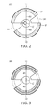
- Fig. 2
- shows a fluorescent wheel of the embodiment of
Fig. 1 ; - Fig. 3
- shows a modified example of the embodiment of
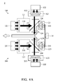
Fig. 1 ; - Fig. 4A
- shows a three-chip digital light processing optical device of an embodiment of the disclosure;
- Fig. 4B
- shows a fluorescent wheel of the embodiment of
Fig. 4A ; - Fig. 5A
- shows a digital light processing optical device of an embodiment of the disclosure utilizing a transmissive fluorescent wheel;
- Fig. 5B
- shows a fluorescent wheel of the embodiment of
Fig. 5A ; - Fig. 5C
- is a side view of the fluorescent wheel of the embodiment of
Fig. 5A ; - Fig. 6A
- shows a fluorescent wheel of an embodiment of the disclosure; and
- Fig. 6B
- shows another fluorescent wheel of an embodiment of the disclosure.
- The following description is of the best-contemplated mode of carrying out the disclosure. This description is made for the purpose of illustrating the general principles of the disclosure and should not be taken in a limiting sense. The scope of the disclosure is best determined by reference to the appended claims.
-
Fig. 1 shows anoptical device 1 of a first embodiment of the disclosure, including afluorescent wheel 10, a firstlight source engine 100 and a secondlight source engine 200. -
Fig. 2 shows afluorescent wheel 10 of an embodiment of the disclosure. Thefluorescent wheel 10 includes afluorescent powder area 15 coated with fluorescent powder. With reference toFigs. 1 and2 , the firstlight source engine 100 provides afirst light beam 110. - The
first light beam 110 forms afirst light spot 11 on thefluorescent powder area 15 of thefluorescent wheel 10. The secondlight source engine 200 provides a secondlight beam 210. - The second
light beam 210 forms a secondlight spot 12 on thefluorescent powder area 15 of thefluorescent wheel 10, and thefirst light spot 11 is separated from the secondlight spot 12. - In one embodiment, a first straight line S1 passes through the center C of the
fluorescent wheel 10 and thefirst light spot 11. A second straight line S2 passes through the center C of thefluorescent wheel 10 and the secondlight spot 12. An included angle θ between the first straight line S1 and the second straight line S2 is between 45 and 180 degrees. In this embodiment, the included angle θ between the first straight line S1 and the second straight line S2 is 180 degrees. In another embodiment, the included angle θ between the first straight line S1 and the second straight line S2 can be 45 degrees. - In the embodiment mentioned above, the first light spot is separated from the second light spot to decrease the power of single one light spot, and the heat accumulation is therefore decreased. In the conventional concept, considering the high rotation speed of the fluorescent wheel, the heat accumulation cannot be decreased even if the first light spot is separated from the second light spot. However, after experimentation, the applicant found that the heat accumulation can be markedly decreased by separating the first light spot from the second light spot. Particularly when the phase angle between the first light spot and the second light spot is between 45 and 180 degrees (180 degrees being preferred), the heat accumulation is decreased, thermal decay is prevented, and the inducing efficiency of the fluorescent element is maintained. In one embodiment, the power of the
first light spot 11 is 95W, and the power of the secondlight spot 12 is 95W. Compared to the conventional design utilizing a single light spot with 190W, the temperature of the fluorescent wheel of the embodiment of the disclosure is only 160°C the conventional design is 190°C, and the illumination of the embodiment of the disclosure can be increased 4% to 5%. - In the embodiment mentioned above, the distance between the first light spot and the center of the fluorescent wheel equals the distance between the second light spot and the center of the fluorescent wheel. However, the disclosure is not meant to restrict the disclosure. With reference to
Fig. 3 , in one embodiment, a first distance d1 is formed between thefirst light spot 11 and the center C of thefluorescent wheel 10. A second distance d2 is formed between the secondlight spot 12 and the center C of thefluorescent wheel 10. The first distance d1 differs from the second distance d2. In this embodiment, the heat accumulation is further decreased by the difference between the first distance d1 and the second distance d2. In this embodiment, the power of the first light source engine can be different from the power of the second light source engine to make the temperature of thefluorescent wheel 10 uniform. - With reference to
Fig. 2 , in one embodiment, thefluorescent wheel 10 comprises a firsttransparent portion 13 and a secondtransparent portion 14. When the firsttransparent portion 13 corresponds to the firstlight source engine 100, the secondtransparent portion 14 corresponds to the secondlight source engine 200. Thefirst light beam 110 passes through the firsttransparent portion 13, and the secondlight beam 210 passes through the secondtransparent portion 14. Certainly, thefluorescent wheel 10 rotates continuously. Therefore, when the secondtransparent portion 14 corresponds to the firstlight source engine 100, the firsttransparent portion 13 corresponds to the secondlight source engine 200. Thefirst light beam 110 passes through the secondtransparent portion 14, and the secondlight beam 210 passes through the firsttransparent portion 13. Additionally, the transparent portions can be empty notches or made of transparent material, such as transparent glass. - In one embodiment, the first light source engine is independent from the second light source engine.
Fig. 1 shows an embodiment of single-chip digital light processing optical device. The first light source engine comprises a firstlight source 120, a first lens unit (L1∼L10) and a firstdichroic mirror 130. In a first mode, thefirst light beam 110 travels from the firstlight source 120, and passes through a first lens group (L1, L2) of the first lens unit, the firstdichroic mirror 130, a second lens group (L3, L4) of the first lens unit, thefluorescent wheel 10, a third lens group (L5, L6, L7, L8, L9) of the first lens unit, and a fourth lens group (L10) of the first lens unit to be output (in one embodiment, a blue light is output, wherein thefirst light beam 110 passes through the firsttransparent portion 13 and the secondtransparent portion 14 of the rotating fluorescent wheel 10). In a second mode, thefirst light beam 110 travels from the firstlight source 120, passing through the first lens group (L1, L2) of the first lens unit, the firstdichroic mirror 130, the second lens group (L3, L4) of the first lens unit to thefluorescent wheel 10, then thelight spot 11 is located in thefluorescent powder area 15. The fluorescent powder in thefluorescent powder area 15 of thefluorescent wheel 10 is induced by thefirst light beam 110 and generates a first induced light 111 (in one embodiment, the first induced light is red light and green light). The first inducedlight 111 travels from thefluorescent wheel 10, passing through the second lens group (L4, L3) of the first lens unit, reflected by the firstdichroic mirror 130 and passing through the fourth lens group (L10) of the first lens unit to be output. The second light source engine comprises a secondlight source 220, a second lens unit (L21∼L30) and a seconddichroic mirror 230. In the first mode, the secondlight beam 210 travels from the secondlight source 220, passing through a fifth lens group (L21, L22) of the second lens unit, the seconddichroic mirror 230, a sixth lens group (L23, L24) of the second lens unit, thefluorescent wheel 10, a seventh lens group (L25, L26, L27, L28, L29) of the second lens unit, and an eighth lens group (L30) of the second lens unit to be output (in one embodiment, a blue light is output, wherein thefirst light beam 110 passes through the firsttransparent portion 13 and the secondtransparent portion 14 of the rotating fluorescent wheel 10). In the second mode, the secondlight beam 210 travels from the secondlight source 220, passing through the fifth lens group (L21, L22) of the second lens unit, the seconddichroic mirror 230, the sixth lens group (L23, L24) of the second lens unit to thefluorescent wheel 10, then thelight spot 12 is located in thefluorescent powder area 15. The fluorescent powder in thefluorescent powder area 15 of thefluorescent wheel 10 is induced by the secondlight beam 210 and generates a second induced light 211 (in one embodiment, the second induced light is red light and green light). The second induced light 211 travels from thefluorescent wheel 10, passing through sixth lens group (L24, L23) of the second lens unit, reflected by the seconddichroic mirror 230 and passing through the eighth lens group (L30) of the second lens unit to be output. - The embodiment above shows a single-chip digital light processing optical device. However, the embodiment is not meant to restrict the disclosure.
Fig. 4A shows a three-chip digital light processing optical device 2. In the embodiment ofFig. 4A , the elements with similar functions follow the labels of the embodiment ofFig. 1 . The firstlight source engine 100 comprises a firstsub light source 121, a secondsub light source 122, a first lens unit (L1∼L4) and a firstdichroic mirror 130. The first light beam 110 (in one embodiment, the first light beam is blue light) travels from the firstsub light source 121, passing the first lens group (L1) of the first lens unit, the firstdichroic mirror 130, and the third lens group (L3) of the first lens unit to thefluorescent wheel 10, the fluorescent powder in thefluorescent powder area 15 of thefluorescent wheel 10 is induced by thefirst light beam 110 to generate a first induced light 111 (in one embodiment, the first induced light is red light and green light). The first inducedlight 111 travels from thefluorescent wheel 10, passing through the third lens group (L3) of the first lens unit, and reflected by the firstdichroic mirror 130 to be output through the fourth lens group (L4) of the first lens unit. A thirdlight beam 113 travels from the secondlight source 122, passing the second lens group (L2) of the first lens unit and the firstdichroic mirror 130 to be output through the fourth lens group (L4) of the first lens unit (in one embodiment, the third light beam is blue light). The secondlight source engine 200 comprises a thirdsub light source 221, a fourthsub light source 222, a second lens unit (L21∼L24) and a seconddichroic mirror 230. The second light beam 210 (in one embodiment, the second light beam is blue light) travels from the thirdsub light source 221, passing the fifth lens group (L21) of the second lens unit, the seconddichroic mirror 230 and the seventh lens group (L23) to thefluorescent wheel 10. The fluorescent powder in thefluorescent powder area 15 of thefluorescent wheel 10 is induced by the secondlight beam 210 to generate a second induced light 211 (in one embodiment, the second induced light is red light and blue light), and the second induced light 211 travels from thefluorescent wheel 10, passing through the seventh lens group (L23) of the second lens unit, and reflected by the seconddichroic mirror 230 to be output through the eighth lens group (L24) of the second lens unit. Afourth light beam 213 travels from the fourthlight source 222, passing the sixth lens group (L22) of the second lens unit and the seconddichroic mirror 230 to be output through the eighth lens group (L24) of the second lens unit (in one embodiment, the fourth light beam is blue light). - With reference to
Fig. 4B , in the embodiment ofFig. 4A , thefluorescent wheel 10 has no transparent portion. - In one embodiment, a transmissive fluorescent wheel is utilizes. With reference to
Fig. 5A , in this embodiment, the firstlight source engine 100 of theoptical device 3 comprises a firstlight source 120, a first lens unit (L1∼L3) and afirst reflector 140. The first light beam 110 (in this embodiment, the first light beam is blue light) travels from the firstlight source 120, passing through the first lens group (L1) of the first lens unit and thefluorescent wheel 10, the second lens group (L2) of the first lens unit, thefirst reflector 140 and the third lens group (L3) of the first lens unit to be output. A plurality of gaps are formed within the fluorescent powder in thefluorescent powder area 15 of thefluorescent wheel 10. Therefore, a portion of the first light beam directly passing through thefluorescent wheel 10 via the gaps, and the fluorescent powder in thefluorescent powder area 15 of the fluorescent wheel is induced by the other portion of thefirst light beam 110 to generate a first induced light (in this embodiment, the first induced light is red light and green light). The first induced light passes through the fluorescent wheel 10 (the first induced light and the portion of the first light beam directly passing through the fluorescent wheel are presented by a first combination light 114). The first combination light 114 is reflected by thefirst reflector 140 to be output. The secondlight source engine 200 comprises a secondlight source 220, a second lens unit (L21∼L23) and asecond reflector 240. The second light beam 210 (in this embodiment, the second light beam is blue light) travels from the secondlight source 220, passing through the fourth lens group (L21) of the second lens unit, the fluorescent wheel, the fifth lens group (L22) of the second lens unit, thesecond reflector 240 and the six lens group (L23) of the second lens unit to be output. A plurality of gaps are formed within the fluorescent powder in thefluorescent powder area 15 of thefluorescent wheel 10. Therefore, a portion of the secondlight beam 210 directly passing through thefluorescent wheel 10 via the gaps, and the fluorescent powder in thefluorescent powder area 15 of the fluorescent wheel is induced by the other portion of the secondlight beam 210 to generate a second induced light (in this embodiment, the second induced light is red light and green light). The second induced light passes through the fluorescent wheel 10 (the second induced light and the portion of the second light beam directly passing through the fluorescent wheel are presented by a second combination light 214). The second combination light 214 is reflected by thesecond reflector 240 to be output. -
Figs. 5B and 5C show thefluorescent wheel 10 of the embodiment ofFig. 5A , wherein thefluorescent wheel 10 has no transparent portion. Thefluorescent wheel 10 comprises atransmissive substrate 17, aspectral coating layer 16 and a fluorescentagents coating layer 18. Thetransmissive substrate 17 is made of glass. Thespectral coating layer 16 allows a blue light to pass through and reflects a yellow light. -
Figs. 6A and 6B show another embodiment of the disclosure, wherein thefluorescent wheel 10 has a firsttransparent portion 13 and a secondtransparent portion 14. The fluorescent powder area of thefluorescent wheel 10 comprises a first section (green fluorescent powder) A1, a second section (yellow fluorescent powder) A2 and a third section (yellow fluorescent powder) A3. The color of the first section A1 differs from the color of the second section A2. The color of the third section A3 differs from the color of the first section A1. The first section A1, the second section A2 and the third section A3 are arranged along the circumference of the fluorescent wheel. In this embodiment, the color of the second section A2 is the same as the color of the third section A3, however, the disclosure is not meant to restrict the disclosure. A first distance is formed between thefirst light spot 11 and the center C of thefluorescent wheel 10. A second distance is formed between the secondlight spot 12 and the center C of thefluorescent wheel 10. The first distance can be the same as the second distance (Fig. 6A ). In another embodiment, the first distance can be different from the second distance (Fig. 6B ). The colors of the first section, the second section and the third section can be modified in other embodiments. - Use of ordinal terms such as "first", "second", "third", etc., in the claims to modify a claim element does not by itself connote any priority, precedence, or order of one claim element over another or the temporal order in which acts of a method are performed, but are used merely as labels to distinguish one claim element having a certain name from another element having the same name (but for use of the ordinal term).
- While the disclosure has been described by way of example and in terms of the preferred embodiments, it is to be understood that the disclosure is not limited to the disclosed embodiments. On the contrary, it is intended to cover various modifications and similar arrangements (as would be apparent to those skilled in the art). Therefore, the scope of the appended claims should be accorded the broadest interpretation so as to encompass all such modifications and similar arrangements.
Claims (12)
- An optical device, comprising:a fluorescent wheel, comprising a fluorescent powder area;a first light source engine, providing a first light beam, wherein the first light beam forms a first light spot on the fluorescent powder area of the fluorescent wheel; anda second light source engine, providing a second light beam, wherein the second light beam forms a second light spot on the fluorescent powder area of the fluorescent wheel, and the first light spot is separated from the second light spot.
- The optical device as claimed in claim 1, wherein an angle included between a first straight line that passes through a center of the fluorescent wheel and the first light spot and a second straight line that passes through the center of the fluorescent wheel and the second light spot is in the range between 45 degrees and 180 degrees.
- The optical device as claimed in claim 1 or 2, wherein a first distance is formed between the first light spot and a center of the fluorescent wheel, a second distance is formed between the second light spot and the center of the fluorescent wheel, and the first distance differs from the second distance.
- The optical device as claimed in any of the preceding claims, wherein the fluorescent wheel comprises a first transparent portion and a second transparent portion, and when the first transparent portion corresponds to the first light source engine, the second transparent portion corresponds to the second light source engine, and the first light beam passes through the first transparent portion, and the second light beam passes through the second transparent portion.
- The optical device as claimed in any of the preceding claims, wherein the first light source engine is independent from the second light source engine.
- The optical device as claimed in claim 4, wherein
the first light source engine comprises a first light source, a first lens unit and a first dichroic mirror, wherein
in a first mode, the first light beam travels from the first light source, passing through a first lens group of the first lens unit, the first dichroic mirror, a second lens group of the first lens unit, the first transparent portion or the second transparent portion of the fluorescent wheel, a third lens group of the first lens unit, and a fourth lens group of the first lens unit to be output, wherein
in a second mode, the first light beam travels from the first light source, passing through the first lens group of the first lens unit, the first dichroic mirror, and the second lens group of the first lens unit to the fluorescent wheel, and
fluorescent powder in the fluorescent powder area of the fluorescent wheel is induced by the first light beam and generates a first induced light, and the first induced light travels from the fluorescent wheel, passing through the second lens group of the first lens unit, reflected by the first dichroic mirror and passing through the fourth lens group of the first lens unit to be output. - The optical device as claimed in claim 6, wherein
the second light source engine comprises a second light source, a second lens unit and a second dichroic mirror, wherein
in the first mode, the second light beam travels from the second light source, passing through a fifth lens group of the second lens unit, the second dichroic mirror, a sixth lens group of the second lens unit, the first transparent portion or the second transparent portion of the fluorescent wheel, a seventh lens group of the second lens unit, and an eighth lens group of the second lens unit to be output, wherein
in the second mode, the second light beam travels from the second light source, passing through the fifth lens group of the second lens unit, the second dichroic mirror, and the sixth lens group of the second lens unit to the fluorescent wheel, and
the fluorescent powder in the fluorescent powder area of the fluorescent wheel is induced by the second light beam and generates a second induced light, and the second induced light travels from the fluorescent wheel, passing through sixth lens group of the second lens unit, reflected by the second dichroic mirror and passing through the eighth lens group of the second lens unit to be output. - The optical device as claimed in any of the preceding claims, wherein
the first light source engine comprises a first sub light source, a second sub light source, a first lens unit and a first dichroic mirror, wherein the first light beam travels from the first sub light source, passing a portion of the first lens unit, and the first dichroic mirror to the fluorescent wheel, fluorescent powder in the fluorescent powder area of the fluorescent wheel is induced by the first light beam to generate a first induced light, and the first induced light travels from the fluorescent wheel, passing through a portion of the first lens unit, and reflected by the first dichroic mirror to be output, and a third light beam travels from the second light source, passing a portion of the first lens unit and the first dichroic mirror to be output. - The optical device as claimed in claim 8, wherein the second light source engine comprises a third sub light source, a fourth sub light source, a second lens unit and a second dichroic mirror, wherein the second light beam travels from the third sub light source, passing a portion of the second lens unit, and the second dichroic mirror to the fluorescent wheel, the fluorescent powder in the fluorescent powder area of the fluorescent wheel is induced by the second light beam to generate a second induced light, and the second induced light travels from the fluorescent wheel, passing through a portion of the second lens unit, and reflected by the second dichroic mirror to be output, and a fourth light beam travels from the fourth sub light source, passing a portion of the second lens unit and the second dichroic mirror to be output.
- The optical device as claimed in claim 4, wherein the first light source engine comprises a first light source, a first lens unit and a first reflector, wherein the first light beam travels from the first light source, passing through a portion of the first lens unit and the fluorescent wheel, a portion of the first light beam directly passing through the fluorescent wheel, fluorescent powder in the fluorescent powder area of the fluorescent wheel is induced by the other portion of the first light beam to generate a first induced light, and the first induced light passes through the fluorescent wheel, and both the first induced light and the portion of the first light beam directly passing through the fluorescent wheel are reflected by the first reflector to be output.
- The optical device as claimed in claim 10, wherein the second light source engine comprises a second light source, a second lens unit and a second reflector, wherein the second light beam travels from the second light source, passing through a portion of the second lens unit and the fluorescent wheel, a portion of the second light beam directly passing through the fluorescent wheel, the fluorescent powder in the fluorescent powder area of the fluorescent wheel is induced by the other portion of the second light beam to generate a second induced light, and the second induced light passes through the fluorescent wheel, and both the second induced light and the portion of the second light beam directly passing through the fluorescent wheel are reflected by the second reflector to be output.
- The optical device as claimed in any of claims 1 to 11, wherein the fluorescent powder area of the fluorescent wheel comprises a first section, a second section and a third section, a color of the first section differs from a color of the second section, a color of the third section differs from the color of the first section, and the first section, the second section and the third section are arranged along a circumference of the fluorescent wheel.
Applications Claiming Priority (1)
| Application Number | Priority Date | Filing Date | Title |
|---|---|---|---|
| US201562136126P | 2015-03-20 | 2015-03-20 |
Publications (2)
| Publication Number | Publication Date |
|---|---|
| EP3070525A1 true EP3070525A1 (en) | 2016-09-21 |
| EP3070525B1 EP3070525B1 (en) | 2017-11-01 |
Family
ID=54834658
Family Applications (1)
| Application Number | Title | Priority Date | Filing Date |
|---|---|---|---|
| EP15197987.9A Active EP3070525B1 (en) | 2015-03-20 | 2015-12-04 | Optical device |
Country Status (5)
| Country | Link |
|---|---|
| US (1) | US10088130B2 (en) |
| EP (1) | EP3070525B1 (en) |
| JP (1) | JP6207649B2 (en) |
| CN (1) | CN105988274A (en) |
| TW (1) | TWI585505B (en) |
Families Citing this family (3)
| Publication number | Priority date | Publication date | Assignee | Title |
|---|---|---|---|---|
| CN106527026A (en) * | 2016-12-09 | 2017-03-22 | 上海晟智电子科技有限公司 | Laser projection light source realization apparatus and method |
| CN108267913B (en) * | 2016-12-30 | 2021-06-08 | 中强光电股份有限公司 | Light source module and projection device |
| CN113138525B (en) * | 2020-01-20 | 2024-03-22 | 苏州佳世达光电有限公司 | Projection device |
Citations (4)
| Publication number | Priority date | Publication date | Assignee | Title |
|---|---|---|---|---|
| US20120300178A1 (en) * | 2011-05-25 | 2012-11-29 | Panasonic Corporation | Lighting Device and Projection-Type Display Apparatus Including Lighting Device |
| US20130033682A1 (en) * | 2011-08-03 | 2013-02-07 | Hon Hai Precision Industry Co., Ltd. | Light source device and projector having same |
| CN202771146U (en) * | 2012-07-12 | 2013-03-06 | 芜湖雅图数字视频技术有限公司 | Dual-lamp lighting device and projector |
| WO2014174559A1 (en) * | 2013-04-22 | 2014-10-30 | 日立マクセル株式会社 | Light source apparatus and image display apparatus |
Family Cites Families (10)
| Publication number | Priority date | Publication date | Assignee | Title |
|---|---|---|---|---|
| TW200700883A (en) * | 2005-06-20 | 2007-01-01 | Benq Corp | Light source module of a projector and color wheel thereof |
| JP5617288B2 (en) * | 2010-03-18 | 2014-11-05 | セイコーエプソン株式会社 | Lighting device and projector |
| JP5767444B2 (en) * | 2010-06-16 | 2015-08-19 | ソニー株式会社 | Light source device and image projection device |
| JP5914878B2 (en) * | 2011-04-20 | 2016-05-11 | パナソニックIpマネジメント株式会社 | Light source device and projection display device |
| JP5987382B2 (en) * | 2011-07-22 | 2016-09-07 | 株式会社リコー | LIGHTING DEVICE, PROJECTION DEVICE, AND METHOD FOR CONTROLLING PROJECTION DEVICE |
| TWI443441B (en) * | 2012-02-09 | 2014-07-01 | Delta Electronics Inc | Light source system |
| TWI467242B (en) * | 2012-05-29 | 2015-01-01 | Delta Electronics Inc | Projection apparatus for providing multiple viewing angle images |
| TWI468842B (en) * | 2013-05-07 | 2015-01-11 | 台達電子工業股份有限公司 | Method for regulating the wavelength of light emitted from a projection device |
| US9664989B2 (en) | 2013-05-23 | 2017-05-30 | Texas Instruments Incorporated | Multi-spatial light modulator image display projector architectures using solid state light sources |
| TW201503515A (en) * | 2013-07-12 | 2015-01-16 | Delta Electronics Inc | Laser light source module for using in projection system |
-
2015
- 2015-07-03 TW TW104121612A patent/TWI585505B/en active
- 2015-07-03 CN CN201510385594.7A patent/CN105988274A/en active Pending
- 2015-11-24 US US14/950,920 patent/US10088130B2/en active Active
- 2015-12-04 EP EP15197987.9A patent/EP3070525B1/en active Active
-
2016
- 2016-03-18 JP JP2016054705A patent/JP6207649B2/en active Active
Patent Citations (4)
| Publication number | Priority date | Publication date | Assignee | Title |
|---|---|---|---|---|
| US20120300178A1 (en) * | 2011-05-25 | 2012-11-29 | Panasonic Corporation | Lighting Device and Projection-Type Display Apparatus Including Lighting Device |
| US20130033682A1 (en) * | 2011-08-03 | 2013-02-07 | Hon Hai Precision Industry Co., Ltd. | Light source device and projector having same |
| CN202771146U (en) * | 2012-07-12 | 2013-03-06 | 芜湖雅图数字视频技术有限公司 | Dual-lamp lighting device and projector |
| WO2014174559A1 (en) * | 2013-04-22 | 2014-10-30 | 日立マクセル株式会社 | Light source apparatus and image display apparatus |
Also Published As
| Publication number | Publication date |
|---|---|
| US20160273737A1 (en) | 2016-09-22 |
| TWI585505B (en) | 2017-06-01 |
| CN105988274A (en) | 2016-10-05 |
| EP3070525B1 (en) | 2017-11-01 |
| US10088130B2 (en) | 2018-10-02 |
| TW201635003A (en) | 2016-10-01 |
| JP6207649B2 (en) | 2017-10-04 |
| JP2016177286A (en) | 2016-10-06 |
Similar Documents
| Publication | Publication Date | Title |
|---|---|---|
| JP6968744B2 (en) | Wavelength conversion filter module and lighting system | |
| CN104749865B (en) | Wavelength conversion device and projector | |
| US10368043B2 (en) | Projector and illumination system thereof | |
| US11448950B2 (en) | Combination wheel for light conversion including both phosphor segments and color filters | |
| EP3422066B1 (en) | FLUORESCENT WHEEL | |
| US7506985B2 (en) | Projection light source having multiple light emitting diodes | |
| WO2013046483A1 (en) | Light source device | |
| CN104870887B (en) | Light source device | |
| US11022872B2 (en) | Projection system | |
| CN102445829A (en) | Light source unit, illumination device, and projection display apparatus | |
| US10268111B2 (en) | Phosphor wheel, light source device, and projector-type image display apparatus | |
| CN104204897A (en) | Lens having internal reflection layer | |
| US9869926B2 (en) | Wavelength conversion element, light source device, and projector | |
| TWM565813U (en) | Wavelength conversion wheel and projection device | |
| WO2014174559A1 (en) | Light source apparatus and image display apparatus | |
| US10088130B2 (en) | Optical device | |
| CN114488671A (en) | Projection device and lighting system | |
| US11172177B2 (en) | Projection system | |
| CN108292085B (en) | projector device | |
| EP3185317B1 (en) | Phosphor device and manufacturing method thereof | |
| CN211123606U (en) | Wavelength conversion device and projection device | |
| US20140204349A1 (en) | Illumination system and projection device comprising the same | |
| US20240272534A1 (en) | Fluorescent light-emitting module, projector, and phosphor wheel | |
| US20220252240A1 (en) | Light source module | |
| US20220170613A1 (en) | Optical element, vehicle headlight, light source device, and projection device |
Legal Events
| Date | Code | Title | Description |
|---|---|---|---|
| PUAI | Public reference made under article 153(3) epc to a published international application that has entered the european phase |
Free format text: ORIGINAL CODE: 0009012 |
|
| AK | Designated contracting states |
Kind code of ref document: A1 Designated state(s): AL AT BE BG CH CY CZ DE DK EE ES FI FR GB GR HR HU IE IS IT LI LT LU LV MC MK MT NL NO PL PT RO RS SE SI SK SM TR |
|
| AX | Request for extension of the european patent |
Extension state: BA ME |
|
| STAA | Information on the status of an ep patent application or granted ep patent |
Free format text: STATUS: REQUEST FOR EXAMINATION WAS MADE |
|
| 17P | Request for examination filed |
Effective date: 20170209 |
|
| RBV | Designated contracting states (corrected) |
Designated state(s): AL AT BE BG CH CY CZ DE DK EE ES FI FR GB GR HR HU IE IS IT LI LT LU LV MC MK MT NL NO PL PT RO RS SE SI SK SM TR |
|
| GRAP | Despatch of communication of intention to grant a patent |
Free format text: ORIGINAL CODE: EPIDOSNIGR1 |
|
| STAA | Information on the status of an ep patent application or granted ep patent |
Free format text: STATUS: GRANT OF PATENT IS INTENDED |
|
| RAP1 | Party data changed (applicant data changed or rights of an application transferred) |
Owner name: DELTA ELECTRONICS, INC. |
|
| INTG | Intention to grant announced |
Effective date: 20170530 |
|
| GRAS | Grant fee paid |
Free format text: ORIGINAL CODE: EPIDOSNIGR3 |
|
| GRAA | (expected) grant |
Free format text: ORIGINAL CODE: 0009210 |
|
| STAA | Information on the status of an ep patent application or granted ep patent |
Free format text: STATUS: THE PATENT HAS BEEN GRANTED |
|
| AK | Designated contracting states |
Kind code of ref document: B1 Designated state(s): AL AT BE BG CH CY CZ DE DK EE ES FI FR GB GR HR HU IE IS IT LI LT LU LV MC MK MT NL NO PL PT RO RS SE SI SK SM TR |
|
| REG | Reference to a national code |
Ref country code: GB Ref legal event code: FG4D |
|
| REG | Reference to a national code |
Ref country code: CH Ref legal event code: EP Ref country code: AT Ref legal event code: REF Ref document number: 942618 Country of ref document: AT Kind code of ref document: T Effective date: 20171115 |
|
| REG | Reference to a national code |
Ref country code: FR Ref legal event code: PLFP Year of fee payment: 3 |
|
| REG | Reference to a national code |
Ref country code: IE Ref legal event code: FG4D |
|
| REG | Reference to a national code |
Ref country code: DE Ref legal event code: R096 Ref document number: 602015005716 Country of ref document: DE |
|
| REG | Reference to a national code |
Ref country code: NL Ref legal event code: MP Effective date: 20171101 |
|
| REG | Reference to a national code |
Ref country code: LT Ref legal event code: MG4D |
|
| REG | Reference to a national code |
Ref country code: AT Ref legal event code: MK05 Ref document number: 942618 Country of ref document: AT Kind code of ref document: T Effective date: 20171101 |
|
| PG25 | Lapsed in a contracting state [announced via postgrant information from national office to epo] |
Ref country code: FI Free format text: LAPSE BECAUSE OF FAILURE TO SUBMIT A TRANSLATION OF THE DESCRIPTION OR TO PAY THE FEE WITHIN THE PRESCRIBED TIME-LIMIT Effective date: 20171101 Ref country code: SE Free format text: LAPSE BECAUSE OF FAILURE TO SUBMIT A TRANSLATION OF THE DESCRIPTION OR TO PAY THE FEE WITHIN THE PRESCRIBED TIME-LIMIT Effective date: 20171101 Ref country code: NL Free format text: LAPSE BECAUSE OF FAILURE TO SUBMIT A TRANSLATION OF THE DESCRIPTION OR TO PAY THE FEE WITHIN THE PRESCRIBED TIME-LIMIT Effective date: 20171101 Ref country code: ES Free format text: LAPSE BECAUSE OF FAILURE TO SUBMIT A TRANSLATION OF THE DESCRIPTION OR TO PAY THE FEE WITHIN THE PRESCRIBED TIME-LIMIT Effective date: 20171101 Ref country code: LT Free format text: LAPSE BECAUSE OF FAILURE TO SUBMIT A TRANSLATION OF THE DESCRIPTION OR TO PAY THE FEE WITHIN THE PRESCRIBED TIME-LIMIT Effective date: 20171101 Ref country code: NO Free format text: LAPSE BECAUSE OF FAILURE TO SUBMIT A TRANSLATION OF THE DESCRIPTION OR TO PAY THE FEE WITHIN THE PRESCRIBED TIME-LIMIT Effective date: 20180201 |
|
| PG25 | Lapsed in a contracting state [announced via postgrant information from national office to epo] |
Ref country code: LV Free format text: LAPSE BECAUSE OF FAILURE TO SUBMIT A TRANSLATION OF THE DESCRIPTION OR TO PAY THE FEE WITHIN THE PRESCRIBED TIME-LIMIT Effective date: 20171101 Ref country code: BG Free format text: LAPSE BECAUSE OF FAILURE TO SUBMIT A TRANSLATION OF THE DESCRIPTION OR TO PAY THE FEE WITHIN THE PRESCRIBED TIME-LIMIT Effective date: 20180201 Ref country code: HR Free format text: LAPSE BECAUSE OF FAILURE TO SUBMIT A TRANSLATION OF THE DESCRIPTION OR TO PAY THE FEE WITHIN THE PRESCRIBED TIME-LIMIT Effective date: 20171101 Ref country code: RS Free format text: LAPSE BECAUSE OF FAILURE TO SUBMIT A TRANSLATION OF THE DESCRIPTION OR TO PAY THE FEE WITHIN THE PRESCRIBED TIME-LIMIT Effective date: 20171101 Ref country code: AT Free format text: LAPSE BECAUSE OF FAILURE TO SUBMIT A TRANSLATION OF THE DESCRIPTION OR TO PAY THE FEE WITHIN THE PRESCRIBED TIME-LIMIT Effective date: 20171101 Ref country code: GR Free format text: LAPSE BECAUSE OF FAILURE TO SUBMIT A TRANSLATION OF THE DESCRIPTION OR TO PAY THE FEE WITHIN THE PRESCRIBED TIME-LIMIT Effective date: 20180202 Ref country code: IS Free format text: LAPSE BECAUSE OF FAILURE TO SUBMIT A TRANSLATION OF THE DESCRIPTION OR TO PAY THE FEE WITHIN THE PRESCRIBED TIME-LIMIT Effective date: 20180301 |
|
| PG25 | Lapsed in a contracting state [announced via postgrant information from national office to epo] |
Ref country code: CZ Free format text: LAPSE BECAUSE OF FAILURE TO SUBMIT A TRANSLATION OF THE DESCRIPTION OR TO PAY THE FEE WITHIN THE PRESCRIBED TIME-LIMIT Effective date: 20171101 Ref country code: DK Free format text: LAPSE BECAUSE OF FAILURE TO SUBMIT A TRANSLATION OF THE DESCRIPTION OR TO PAY THE FEE WITHIN THE PRESCRIBED TIME-LIMIT Effective date: 20171101 Ref country code: EE Free format text: LAPSE BECAUSE OF FAILURE TO SUBMIT A TRANSLATION OF THE DESCRIPTION OR TO PAY THE FEE WITHIN THE PRESCRIBED TIME-LIMIT Effective date: 20171101 Ref country code: CY Free format text: LAPSE BECAUSE OF FAILURE TO SUBMIT A TRANSLATION OF THE DESCRIPTION OR TO PAY THE FEE WITHIN THE PRESCRIBED TIME-LIMIT Effective date: 20171101 Ref country code: SK Free format text: LAPSE BECAUSE OF FAILURE TO SUBMIT A TRANSLATION OF THE DESCRIPTION OR TO PAY THE FEE WITHIN THE PRESCRIBED TIME-LIMIT Effective date: 20171101 |
|
| REG | Reference to a national code |
Ref country code: DE Ref legal event code: R097 Ref document number: 602015005716 Country of ref document: DE |
|
| PG25 | Lapsed in a contracting state [announced via postgrant information from national office to epo] |
Ref country code: RO Free format text: LAPSE BECAUSE OF FAILURE TO SUBMIT A TRANSLATION OF THE DESCRIPTION OR TO PAY THE FEE WITHIN THE PRESCRIBED TIME-LIMIT Effective date: 20171101 Ref country code: SM Free format text: LAPSE BECAUSE OF FAILURE TO SUBMIT A TRANSLATION OF THE DESCRIPTION OR TO PAY THE FEE WITHIN THE PRESCRIBED TIME-LIMIT Effective date: 20171101 Ref country code: IT Free format text: LAPSE BECAUSE OF FAILURE TO SUBMIT A TRANSLATION OF THE DESCRIPTION OR TO PAY THE FEE WITHIN THE PRESCRIBED TIME-LIMIT Effective date: 20171101 Ref country code: PL Free format text: LAPSE BECAUSE OF FAILURE TO SUBMIT A TRANSLATION OF THE DESCRIPTION OR TO PAY THE FEE WITHIN THE PRESCRIBED TIME-LIMIT Effective date: 20171101 |
|
| PLBE | No opposition filed within time limit |
Free format text: ORIGINAL CODE: 0009261 |
|
| STAA | Information on the status of an ep patent application or granted ep patent |
Free format text: STATUS: NO OPPOSITION FILED WITHIN TIME LIMIT |
|
| REG | Reference to a national code |
Ref country code: IE Ref legal event code: MM4A |
|
| PG25 | Lapsed in a contracting state [announced via postgrant information from national office to epo] |
Ref country code: LU Free format text: LAPSE BECAUSE OF NON-PAYMENT OF DUE FEES Effective date: 20171204 Ref country code: MT Free format text: LAPSE BECAUSE OF NON-PAYMENT OF DUE FEES Effective date: 20171204 |
|
| 26N | No opposition filed |
Effective date: 20180802 |
|
| REG | Reference to a national code |
Ref country code: FR Ref legal event code: PLFP Year of fee payment: 4 |
|
| PG25 | Lapsed in a contracting state [announced via postgrant information from national office to epo] |
Ref country code: IE Free format text: LAPSE BECAUSE OF NON-PAYMENT OF DUE FEES Effective date: 20171204 |
|
| PG25 | Lapsed in a contracting state [announced via postgrant information from national office to epo] |
Ref country code: SI Free format text: LAPSE BECAUSE OF FAILURE TO SUBMIT A TRANSLATION OF THE DESCRIPTION OR TO PAY THE FEE WITHIN THE PRESCRIBED TIME-LIMIT Effective date: 20171101 |
|
| PG25 | Lapsed in a contracting state [announced via postgrant information from national office to epo] |
Ref country code: MC Free format text: LAPSE BECAUSE OF FAILURE TO SUBMIT A TRANSLATION OF THE DESCRIPTION OR TO PAY THE FEE WITHIN THE PRESCRIBED TIME-LIMIT Effective date: 20171101 Ref country code: HU Free format text: LAPSE BECAUSE OF FAILURE TO SUBMIT A TRANSLATION OF THE DESCRIPTION OR TO PAY THE FEE WITHIN THE PRESCRIBED TIME-LIMIT; INVALID AB INITIO Effective date: 20151204 |
|
| REG | Reference to a national code |
Ref country code: CH Ref legal event code: PL |
|
| PG25 | Lapsed in a contracting state [announced via postgrant information from national office to epo] |
Ref country code: MK Free format text: LAPSE BECAUSE OF FAILURE TO SUBMIT A TRANSLATION OF THE DESCRIPTION OR TO PAY THE FEE WITHIN THE PRESCRIBED TIME-LIMIT Effective date: 20171101 |
|
| PG25 | Lapsed in a contracting state [announced via postgrant information from national office to epo] |
Ref country code: CH Free format text: LAPSE BECAUSE OF NON-PAYMENT OF DUE FEES Effective date: 20181231 Ref country code: LI Free format text: LAPSE BECAUSE OF NON-PAYMENT OF DUE FEES Effective date: 20181231 |
|
| PG25 | Lapsed in a contracting state [announced via postgrant information from national office to epo] |
Ref country code: TR Free format text: LAPSE BECAUSE OF FAILURE TO SUBMIT A TRANSLATION OF THE DESCRIPTION OR TO PAY THE FEE WITHIN THE PRESCRIBED TIME-LIMIT Effective date: 20171101 |
|
| PG25 | Lapsed in a contracting state [announced via postgrant information from national office to epo] |
Ref country code: PT Free format text: LAPSE BECAUSE OF FAILURE TO SUBMIT A TRANSLATION OF THE DESCRIPTION OR TO PAY THE FEE WITHIN THE PRESCRIBED TIME-LIMIT Effective date: 20171101 |
|
| PG25 | Lapsed in a contracting state [announced via postgrant information from national office to epo] |
Ref country code: AL Free format text: LAPSE BECAUSE OF FAILURE TO SUBMIT A TRANSLATION OF THE DESCRIPTION OR TO PAY THE FEE WITHIN THE PRESCRIBED TIME-LIMIT Effective date: 20171101 |
|
| PGFP | Annual fee paid to national office [announced via postgrant information from national office to epo] |
Ref country code: DE Payment date: 20251022 Year of fee payment: 11 |
|
| PGFP | Annual fee paid to national office [announced via postgrant information from national office to epo] |
Ref country code: GB Payment date: 20251016 Year of fee payment: 11 |
|
| PGFP | Annual fee paid to national office [announced via postgrant information from national office to epo] |
Ref country code: FR Payment date: 20251023 Year of fee payment: 11 |
|
| PGFP | Annual fee paid to national office [announced via postgrant information from national office to epo] |
Ref country code: BE Payment date: 20251117 Year of fee payment: 11 |