EP3070360A2 - Selectable one-way clutch - Google Patents
Selectable one-way clutch Download PDFInfo
- Publication number
- EP3070360A2 EP3070360A2 EP16159370.2A EP16159370A EP3070360A2 EP 3070360 A2 EP3070360 A2 EP 3070360A2 EP 16159370 A EP16159370 A EP 16159370A EP 3070360 A2 EP3070360 A2 EP 3070360A2
- Authority
- EP
- European Patent Office
- Prior art keywords
- plate
- claw
- outer shell
- holding
- state
- Prior art date
- Legal status (The legal status is an assumption and is not a legal conclusion. Google has not performed a legal analysis and makes no representation as to the accuracy of the status listed.)
- Granted
Links
- 210000000078 claw Anatomy 0.000 claims abstract description 58
- 230000005540 biological transmission Effects 0.000 description 8
- 238000006073 displacement reaction Methods 0.000 description 6
- 238000004519 manufacturing process Methods 0.000 description 3
- 238000006243 chemical reaction Methods 0.000 description 2
- 230000002040 relaxant effect Effects 0.000 description 2
- 239000000470 constituent Substances 0.000 description 1
Images


Classifications
-
- F—MECHANICAL ENGINEERING; LIGHTING; HEATING; WEAPONS; BLASTING
- F16—ENGINEERING ELEMENTS AND UNITS; GENERAL MEASURES FOR PRODUCING AND MAINTAINING EFFECTIVE FUNCTIONING OF MACHINES OR INSTALLATIONS; THERMAL INSULATION IN GENERAL
- F16D—COUPLINGS FOR TRANSMITTING ROTATION; CLUTCHES; BRAKES
- F16D41/00—Freewheels or freewheel clutches
- F16D41/12—Freewheels or freewheel clutches with hinged pawl co-operating with teeth, cogs, or the like
- F16D41/125—Freewheels or freewheel clutches with hinged pawl co-operating with teeth, cogs, or the like the pawl movement having an axial component
-
- F—MECHANICAL ENGINEERING; LIGHTING; HEATING; WEAPONS; BLASTING
- F16—ENGINEERING ELEMENTS AND UNITS; GENERAL MEASURES FOR PRODUCING AND MAINTAINING EFFECTIVE FUNCTIONING OF MACHINES OR INSTALLATIONS; THERMAL INSULATION IN GENERAL
- F16D—COUPLINGS FOR TRANSMITTING ROTATION; CLUTCHES; BRAKES
- F16D41/00—Freewheels or freewheel clutches
- F16D41/12—Freewheels or freewheel clutches with hinged pawl co-operating with teeth, cogs, or the like
- F16D41/16—Freewheels or freewheel clutches with hinged pawl co-operating with teeth, cogs, or the like the action being reversible
-
- B—PERFORMING OPERATIONS; TRANSPORTING
- B60—VEHICLES IN GENERAL
- B60W—CONJOINT CONTROL OF VEHICLE SUB-UNITS OF DIFFERENT TYPE OR DIFFERENT FUNCTION; CONTROL SYSTEMS SPECIALLY ADAPTED FOR HYBRID VEHICLES; ROAD VEHICLE DRIVE CONTROL SYSTEMS FOR PURPOSES NOT RELATED TO THE CONTROL OF A PARTICULAR SUB-UNIT
- B60W30/00—Purposes of road vehicle drive control systems not related to the control of a particular sub-unit, e.g. of systems using conjoint control of vehicle sub-units
-
- F—MECHANICAL ENGINEERING; LIGHTING; HEATING; WEAPONS; BLASTING
- F16—ENGINEERING ELEMENTS AND UNITS; GENERAL MEASURES FOR PRODUCING AND MAINTAINING EFFECTIVE FUNCTIONING OF MACHINES OR INSTALLATIONS; THERMAL INSULATION IN GENERAL
- F16D—COUPLINGS FOR TRANSMITTING ROTATION; CLUTCHES; BRAKES
- F16D41/00—Freewheels or freewheel clutches
- F16D41/12—Freewheels or freewheel clutches with hinged pawl co-operating with teeth, cogs, or the like
- F16D41/14—Freewheels or freewheel clutches with hinged pawl co-operating with teeth, cogs, or the like the effective stroke of the pawl being adjustable
Definitions
- the disclosure relates to a selectable one-way clutch.
- JP 2002-514292 A describes a selectable one-way clutch.
- a plate including a claw provided in a projectable manner and a plate including a recessed portion with which the claw meshes are provided on the same axis By changing a state of the claw by a selector plate provided between two plates, a lock mode in which torque transmission between the two plates is allowed only at the time of a rotation in one predetermined direction, or a release mode in which torque transmission between the two plates is blocked only at the time of a rotation in both directions is selectable.
- the disclosure provides a selectable one-way clutch that can reduce displacement between axial centers at the time of joining two plates.
- An example aspect of the disclosure provides a selectable one-way clutch includes a first plate, a second plate, a claw, a selector plate and an outer shell.
- the second plate is placed on the same axis as the first plate, the second plate having a recessed portion.
- the claw is provided in the first plate.
- the claw is configured to project from the first plate toward the second plate.
- the claw is configured to mesh with the recessed portion of the second plate in a state where the claw projects from the first plate only at the time when the second plate rotates in a predetermined rotation direction.
- the selector plate is placed between the first plate and the second plate.
- the selector plate is configured to change a state of the claw between a state where the claw is projectable from the first plate and a state where the claw is maintained to be accommodated on a first-plate side.
- the outer shell is configured to cover an outer periphery of the first plate.
- the first plate is mounted on a holding member such that the first plate is non-rotatable around the axis and moves in a direction of the axis.
- the outer shell is configured to be immovable relative to the holding member in a state where the outer shell is positioned in a radial direction on the basis of the axis.
- the outer periphery of the first plate is covered with the outer shell and an inner periphery of the outer shell that covers the outer periphery of the first plate having a tapered shape in which a diameter is gradually reduced toward a direction distanced from the second plate.
- the claw provided in the first plate meshes with the recessed portion formed in the second plate so that the first plate is joined to the second plate, a force to distance the first plate and the second plate from each other with their axial centers being displaced is applied thereto.
- the inner periphery of the outer shell positioned in the radial direction on the basis of the axis and immovable relative to the holding member on which the first plate is mounted and the outer periphery of the first plate covered with the outer shell are formed in a tapered shape in which a diameter is gradually reduced toward a direction distanced from the second plate.
- the selectable one-way clutch may further include a biasing member.
- the biasing member may be provided between the first plate and the outer shell.
- the biasing member may be configured to bias the first plate and the outer shell in directions where the first plate and the outer shell are distanced from each other. According to the above aspect, when the first plate is released from the second plate, the first plate can be easily returned to an initial position distanced from the outer shell by the biasing member. Further, at the time when the first plate is joined to the second plate, the first plate moves in a direction distanced from the second plate so as to make contact with the outer shell. At this time, an impact caused due to the contact can be relaxed by the biasing member.
- the inner periphery of the outer shell positioned in the radial direction on the basis of the axis and immovable relative to the holding member on which the first plate is mounted and the outer periphery of the first plate covered with the outer shell are formed in a tapered shape in which a diameter is gradually reduced toward a direction distanced from the second plate.
- the inner periphery of the outer shell makes contact with the outer periphery of the first plate, so that the displacement of the axial center of the first plate can be reduced.
- a selectable one-way clutch (hereinafter referred to as a clutch) 1A illustrated in FIGS. 1 to 3 is used by being incorporated into a hybrid transformer axle (not shown).
- the clutch 1A is provided between a fixed shaft 101 fixed to a case 100 and a rotating shaft 102 rotatable around the same axis Ax as the fixed shaft 101.
- the clutch 1A can select an operation mode between a lock mode and a release mode.
- the lock mode is a mode in which a state where torque transmission from the rotating shaft 102 to the fixed shaft 101 is allowed so as to fix the rotating shaft 102 in a case where a rotation direction of the rotating shaft 102 is R1 and a state where the transmission torque is blocked so as to release the rotating shaft 102 in a case where the rotation direction is R2 are switched.
- the release mode is a mode in which torque transmission from the rotating shaft 102 to the fixed shaft 101 is blocked in either case where the rotation direction of the rotating shaft 102 is R1 or R2, so as to maintain the rotating shaft 102 is released.
- the clutch 1A includes: a holding plate 2 splined to the fixed shaft 101 in a state where the holding plate 2 is non-rotatable around the axis Ax but movable in an axis-Ax direction; a rotating plate 3 provided integrally rotatably around the axis Ax with the rotating shaft 102; a selector plate 4 placed between the holding plate 2 and the rotating plate 3 and provided rotatably around the axis Ax; and an outer shell 5 that covers an outer periphery of the holding plate 2.
- the outer shell 5 is fixed to the fixed shaft 101 in a state where the outer shell 5 is positioned in a radial direction based on the axis Ax, so the outer shell 5 is immovable relative to the fixed shaft 101 and the case 100.
- the holding plate 2 is one example of a first plate.
- the rotating plate 3 is one example of a second plate.
- the fixed shaft 101 on which the holding plate 2 is mounted is one example of a holding member.
- a plurality of holding chambers 10 is formed such that the plurality of holding chambers 10 is opened on a side opposed to the rotating plate 3 and arranged in a circumferential direction.
- Each of the holding chambers 10 is provided with one claw 11 meshing with the rotating plate 3.
- a base end 11a of each claw 11 is attached to the holding plate 2 via a spindle P rotatably around an axis Ax1 extending in a radial direction of the holding plate 2, and is biased by a spring 12 in a projection direction toward a rotating-plate-3 side.
- each claw 11 can be operated in a state where the each claw 11 is moved backward toward a holding-plate-2 side and accommodated in the holding chamber 10 or in a state where the each claw 11 projects from the holding plate 2 toward the rotating plate 3. That is, each claw 11 is provided in the holding plate 2 in a projectable state.
- a plurality of recessed portions 15 is formed such that the plurality of recessed portions 15 is opened on a side opposed to the holding plate 2 and arranged in a circumferential direction.
- Each of the recessed portions 15 includes a wall portion 15a with which a tip end 11b of the claw 11 abuts at the time when the projecting claw 11 meshes therewith.
- the number of recessed portions 15 is larger than the number of claws 11, and phases of the recessed portion 15 and phases of the claws 11 are shifted from each other (see FIG. 2 ). Accordingly, some of the plurality of projecting claws 11 mesh with some of the plurality of recessed portions 15.
- a plurality of through holes 16 which is arranged in the circumferential direction and through which the claws 11 projecting can be partially passed is formed with the same phases as the claws 11.
- a rotation position of the selector plate 4 can be switched between a locked position in FIG. 2 at which the claw 11 passes through the through hole 16 so that the claw 11 can mesh with the recessed portion 15 of the rotating plate 3, and a released position in FIG. 3 at which the tip end 11b of the claw 11 abuts with the selector plate 4 so as to limit projection of the claw 11 and maintain the claw 11 to be accommodated on the holding-plate-2 side.
- the lock mode and the release mode are performed selectively.
- the switching of the rotation position of the selector plate 4 is performed by an actuator (not shown).
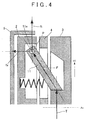
- a torque T is input into the claw 11 as illustrated in FIG. 4 .
- a force F is input into the spindle P placed in the base end 11a of the claw 11 due to the input of the torque T.
- the force F has a component force fx in the axis-Ax direction and a component force ft in a tangent direction of the holding plate 2.
- the holding plate 2 is splined to the fixed shaft 101 so as to be allowed to move in the axis-Ax direction. Accordingly, when the force F is input into the spindle P of the claw 11, the holding plate 2 and the rotating plate 3 are distanced from each other with their axial centers being displaced from each other.
- the clutch 1A is provided with the outer shell 5 for providing an alignment function to return the displaced axial center of the holding plate 2 to a normal place.
- the outer shell 5 is fixed to the fixed shaft 101, so as to cover the holding plate 2 except a facing side 2a that is opposed to the rotating plate 3.
- a predetermined clearance is secured between the outer shell 5 and the holding plate 2.
- An inner periphery 20 of the outer shell 5 is machined with accuracy, so that an inside diameter from the axis Ax to the inner periphery 20 is generally uniform around a whole circumference.
- the inner periphery 20 of the outer shell 5 and an outer periphery 21 of the holding plate 2 are formed in a tapered shape in which a diameter is gradually reduced toward a direction distanced from the rotating plate 3.
- the outer periphery 21 is covered with the inner periphery 20 of the outer shell 5.
- a taper angle ⁇ i of the inner periphery 20 and a taper angle ⁇ o of the outer periphery 21 are set to be equal to each other, but they may be different from each other.
- the inner periphery 20, the outer periphery 21, and a clearance C therebetween are set, so that, at the time when the holding plate 2 is moved in the axis-Ax direction, an opposite side 2b to the facing side 2a of the holding plate 2 does not make contact with an inner surface 5a of the outer shell 5.
- the inner surface 5a is opposed to the holding plate 2.
- a clutch 1B includes a return spring 30 as a biasing member provided between an inner surface 5a of an outer shell 5 and an opposite side 2b of a holding plate 2.
- the return spring 30 biases the holding plate 2 and the outer shell 5 in directions where they are distanced from each other. Note that, in FIGS. 6 and 7 , only one return spring 30 is illustrated. However, in consideration of a balance in a circumferential direction, a plurality of return springs 30 (e.g., six return springs 30) is provided at regular intervals in the circumferential direction of the holding plate 2.
- the holding plate 2 can be easily returned to an initial position (illustrated herein) distanced from the outer shell 5 by the return spring 30. Further, when the holding plate 2 moves in a direction distanced from the rotating plate 3 and makes contact with the outer shell 5 at the time when the holding plate 2 is joined to the rotating plate 3, an impact caused due to the contact can be relaxed by the return spring 30.
- each of the embodiments is just one application example of the clutch.
- the present invention can be carried out in an embodiment in which an outer shell is fixed, and a first plate and a second plate are rotatable relative to each other around the same axis.
- the present invention can be also carried out in an embodiment in which an outer shell and a first plate are integrally rotatable around the same axis and a second plate is rotatable relative to the first plate around the same axis.
- the outer shell 5 covers the holding plate 2 except the facing side 2a that is opposed to the rotating plate 3, but this is just an example.
- the outer shell may just cover the outer periphery of the first plate.
- the present invention can be carried out in an embodiment in which the outer periphery of the first plate is covered with a ring-shaped or tubular outer shell.
- the outer shell 5 is fixed to the fixed shaft 101, but an object to which the outer shell 5 is fixed may be the case 100 that stands still relative to the fixed shaft 101, for example.
- the outer shell may be in an immovable state relative to the holding member on which the first plate is mounted.
Landscapes
- Engineering & Computer Science (AREA)
- General Engineering & Computer Science (AREA)
- Mechanical Engineering (AREA)
- Automation & Control Theory (AREA)
- Transportation (AREA)
- Mechanical Operated Clutches (AREA)
Abstract
Description
- The disclosure relates to a selectable one-way clutch.
- Japanese Patent Application Publication No.
2002-514292 JP 2002-514292 A JP 2002-514292 A - Because of a structure of the selectable one-way clutch of
JP 2002-514292 A - The disclosure provides a selectable one-way clutch that can reduce displacement between axial centers at the time of joining two plates.
- An example aspect of the disclosure provides a selectable one-way clutch includes a first plate, a second plate, a claw, a selector plate and an outer shell. The second plate is placed on the same axis as the first plate, the second plate having a recessed portion. The claw is provided in the first plate. The claw is configured to project from the first plate toward the second plate. The claw is configured to mesh with the recessed portion of the second plate in a state where the claw projects from the first plate only at the time when the second plate rotates in a predetermined rotation direction. The selector plate is placed between the first plate and the second plate. The selector plate is configured to change a state of the claw between a state where the claw is projectable from the first plate and a state where the claw is maintained to be accommodated on a first-plate side. The outer shell is configured to cover an outer periphery of the first plate. The first plate is mounted on a holding member such that the first plate is non-rotatable around the axis and moves in a direction of the axis. The outer shell is configured to be immovable relative to the holding member in a state where the outer shell is positioned in a radial direction on the basis of the axis. The outer periphery of the first plate is covered with the outer shell and an inner periphery of the outer shell that covers the outer periphery of the first plate having a tapered shape in which a diameter is gradually reduced toward a direction distanced from the second plate.
- According to the above configuration, when the claw provided in the first plate meshes with the recessed portion formed in the second plate so that the first plate is joined to the second plate, a force to distance the first plate and the second plate from each other with their axial centers being displaced is applied thereto. The inner periphery of the outer shell positioned in the radial direction on the basis of the axis and immovable relative to the holding member on which the first plate is mounted and the outer periphery of the first plate covered with the outer shell are formed in a tapered shape in which a diameter is gradually reduced toward a direction distanced from the second plate. On this account, in a course where the first plate moves in a direction distanced from the second plate, the inner periphery of the outer shell makes contact with an outer periphery of the first plate, so that an alignment function to reduce the displacement of the axial center of the first plate by the outer shell works. Since such an alignment function works in the selectable one-way clutch, a tolerance at the time of manufacturing design of each part such as the first plate can be increased so as to enlarge an allowable range of the displacement of the axial center. Hereby, when the first plate is joined to the second plate, a conversion amount at the time when part of an impact energy caused due to meshing of the claw with the recessed portion of the second plate is converted into a kinetic energy can be increased. This can contribute to relaxing of an impact force at the time of the meshing of the claw.
- The selectable one-way clutch may further include a biasing member. The biasing member may be provided between the first plate and the outer shell. The biasing member may be configured to bias the first plate and the outer shell in directions where the first plate and the outer shell are distanced from each other. According to the above aspect, when the first plate is released from the second plate, the first plate can be easily returned to an initial position distanced from the outer shell by the biasing member. Further, at the time when the first plate is joined to the second plate, the first plate moves in a direction distanced from the second plate so as to make contact with the outer shell. At this time, an impact caused due to the contact can be relaxed by the biasing member.
- According to the selectable one-way clutch, the inner periphery of the outer shell positioned in the radial direction on the basis of the axis and immovable relative to the holding member on which the first plate is mounted and the outer periphery of the first plate covered with the outer shell are formed in a tapered shape in which a diameter is gradually reduced toward a direction distanced from the second plate. On this account, in a course where the first plate moves in a direction distanced from the second plate, the inner periphery of the outer shell makes contact with the outer periphery of the first plate, so that the displacement of the axial center of the first plate can be reduced.
- Features, advantages, and technical and industrial significance of exemplary embodiments will be described below with reference to the accompanying drawings, in which like numerals denote like elements, and wherein:
-
FIG. 1 is a view illustrating a selectable one-way clutch according to a first embodiment; -
FIG. 2 is a sectional view at the time of a lock mode, taken along a line II-II inFIG 1 ; -
FIG. 3 is a sectional view at the time of a release mode, taken along the line II-II inFIG 1 ; -
FIG. 4 is a view illustrating forces to occur at the time of joining of respective plates; -
FIG. 5 is a partial magnified view of a part V inFIG. 2 ; -
FIG. 6 is a sectional view illustrating a selectable one-way clutch according to a second embodiment; and -
FIG. 7 is a partial magnified view of a part VII inFIG. 6 . - (First Embodiment) A selectable one-way clutch (hereinafter referred to as a clutch) 1A illustrated in
FIGS. 1 to 3 is used by being incorporated into a hybrid transformer axle (not shown). Theclutch 1A is provided between afixed shaft 101 fixed to acase 100 and a rotatingshaft 102 rotatable around the same axis Ax as thefixed shaft 101. Theclutch 1A can select an operation mode between a lock mode and a release mode. The lock mode is a mode in which a state where torque transmission from the rotatingshaft 102 to the fixedshaft 101 is allowed so as to fix the rotatingshaft 102 in a case where a rotation direction of the rotatingshaft 102 is R1 and a state where the transmission torque is blocked so as to release the rotatingshaft 102 in a case where the rotation direction is R2 are switched. The release mode is a mode in which torque transmission from the rotatingshaft 102 to thefixed shaft 101 is blocked in either case where the rotation direction of the rotatingshaft 102 is R1 or R2, so as to maintain the rotatingshaft 102 is released. - The
clutch 1A includes: aholding plate 2 splined to thefixed shaft 101 in a state where theholding plate 2 is non-rotatable around the axis Ax but movable in an axis-Ax direction; arotating plate 3 provided integrally rotatably around the axis Ax with therotating shaft 102; aselector plate 4 placed between theholding plate 2 and therotating plate 3 and provided rotatably around the axis Ax; and anouter shell 5 that covers an outer periphery of theholding plate 2. Theouter shell 5 is fixed to thefixed shaft 101 in a state where theouter shell 5 is positioned in a radial direction based on the axis Ax, so theouter shell 5 is immovable relative to thefixed shaft 101 and thecase 100. Theholding plate 2 is one example of a first plate. Therotating plate 3 is one example of a second plate. Thefixed shaft 101 on which theholding plate 2 is mounted is one example of a holding member. - In the
holding plate 2, a plurality ofholding chambers 10 is formed such that the plurality ofholding chambers 10 is opened on a side opposed to therotating plate 3 and arranged in a circumferential direction. Each of theholding chambers 10 is provided with oneclaw 11 meshing with therotating plate 3. Abase end 11a of eachclaw 11 is attached to theholding plate 2 via a spindle P rotatably around an axis Ax1 extending in a radial direction of theholding plate 2, and is biased by aspring 12 in a projection direction toward a rotating-plate-3 side. Hereby, eachclaw 11 can be operated in a state where the eachclaw 11 is moved backward toward a holding-plate-2 side and accommodated in theholding chamber 10 or in a state where the eachclaw 11 projects from theholding plate 2 toward therotating plate 3. That is, eachclaw 11 is provided in theholding plate 2 in a projectable state. - In the
rotating plate 3, a plurality of recessedportions 15 is formed such that the plurality of recessedportions 15 is opened on a side opposed to theholding plate 2 and arranged in a circumferential direction. Each of therecessed portions 15 includes awall portion 15a with which atip end 11b of theclaw 11 abuts at the time when the projectingclaw 11 meshes therewith. Although not illustrated herein, the number of recessedportions 15 is larger than the number ofclaws 11, and phases of the recessedportion 15 and phases of theclaws 11 are shifted from each other (seeFIG. 2 ). Accordingly, some of the plurality of projectingclaws 11 mesh with some of the plurality of recessedportions 15. - In the
selector plate 4, a plurality of throughholes 16 which is arranged in the circumferential direction and through which theclaws 11 projecting can be partially passed is formed with the same phases as theclaws 11. A rotation position of theselector plate 4 can be switched between a locked position inFIG. 2 at which theclaw 11 passes through the throughhole 16 so that theclaw 11 can mesh with the recessedportion 15 of therotating plate 3, and a released position inFIG. 3 at which thetip end 11b of theclaw 11 abuts with theselector plate 4 so as to limit projection of theclaw 11 and maintain theclaw 11 to be accommodated on the holding-plate-2 side. Hereby, the lock mode and the release mode are performed selectively. The switching of the rotation position of theselector plate 4 is performed by an actuator (not shown). - As is apparent from
FIG. 2 , at the time when a rotation direction of therotating plate 3 is R1, thetip end 11b of theclaw 11 abuts with thewall portion 15a of the recessedportion 15. Accordingly, theclaw 11 meshes with the recessedportion 15 of therotating plate 3, so that the holdingplate 2 is joined to therotating plate 3, thereby allowing torque transmission therebetween and fixing therotating shaft 102. In the meantime, at the time when the rotation direction of therotating plate 3 is R2, since theclaw 11 is inclined toward a direction of R2, even if theclaw 11 interferes with the recessedportion 15 of therotating plate 3, theclaw 11 is just pushed back toward the holding-plate-2 side. On that account, theclaw 11 does not mesh with the recessedportion 15. Accordingly, in a case of the lock mode inFIG. 2 , at the time when the rotation direction of therotating plate 3 is R2, torque transmission between the holdingplate 2 and therotating plate 3 is blocked and therotating plate 3 is released. - In the meantime, in a case of the release mode in
FIG. 3 , theclaws 11 are maintained to be accommodated on the holding-plate-2 side by theselector plate 4, so that theclaws 11 do not reach the recessedportions 15 of therotating plate 3. Accordingly, even if the rotation direction of therotating plate 3 is either R1 or R2, torque transmission from therotating plate 3 to the holdingplate 2 is blocked, so that therotating plate 3 is released. - When the
claw 11 meshes with the recessedportion 15 in the lock mode so that the holdingplate 2 is joined to therotating plate 3, a torque T is input into theclaw 11 as illustrated inFIG. 4 . A force F is input into the spindle P placed in thebase end 11a of theclaw 11 due to the input of the torque T. The force F has a component force fx in the axis-Ax direction and a component force ft in a tangent direction of the holdingplate 2. As described above, the holdingplate 2 is splined to the fixedshaft 101 so as to be allowed to move in the axis-Ax direction. Accordingly, when the force F is input into the spindle P of theclaw 11, the holdingplate 2 and therotating plate 3 are distanced from each other with their axial centers being displaced from each other. - The clutch 1A is provided with the
outer shell 5 for providing an alignment function to return the displaced axial center of the holdingplate 2 to a normal place. As described above, theouter shell 5 is fixed to the fixedshaft 101, so as to cover the holdingplate 2 except a facingside 2a that is opposed to therotating plate 3. A predetermined clearance is secured between theouter shell 5 and the holdingplate 2. Aninner periphery 20 of theouter shell 5 is machined with accuracy, so that an inside diameter from the axis Ax to theinner periphery 20 is generally uniform around a whole circumference. - As illustrated in
FIG. 5 , theinner periphery 20 of theouter shell 5 and anouter periphery 21 of the holdingplate 2 are formed in a tapered shape in which a diameter is gradually reduced toward a direction distanced from therotating plate 3. Theouter periphery 21 is covered with theinner periphery 20 of theouter shell 5. A taper angle θi of theinner periphery 20 and a taper angle θo of theouter periphery 21 are set to be equal to each other, but they may be different from each other. Further, theinner periphery 20, theouter periphery 21, and a clearance C therebetween are set, so that, at the time when the holdingplate 2 is moved in the axis-Ax direction, anopposite side 2b to the facingside 2a of the holdingplate 2 does not make contact with aninner surface 5a of theouter shell 5. Theinner surface 5a is opposed to the holdingplate 2. - Hereby, when the
inner periphery 20 of theouter shell 5 makes contact with theouter periphery 21 of the holdingplate 2 in a course where the holdingplate 2 moves in a direction distanced from therotating plate 3, the alignment function to reduce the displacement of the axial enter of the holdingplate 2 by theouter shell 5 works. Accordingly, since such an alignment function works in the clutch 1A at the time when the holdingplate 2 is joined to therotating plate 3, a tolerance at the time of manufacturing design of each part such as the holdingplate 2 can be increased so as to enlarge an allowable range of the displacement of the axial center. Hereby, when the holdingplate 2 is joined to therotating plate 3, a conversion amount at the time when part of an impact energy caused due to meshing of theclaw 11 with the recessedportion 15 of therotating plate 3 is converted into a kinetic energy can be increased. This can contribute to relaxing of an impact force at the time of the meshing of theclaw 11. - (Second Embodiment) Next will be described a second embodiment of the present invention with reference to
FIGS. 6 and7 . In the following description, the same constituent as in the first embodiment has the same reference sign as in the first embodiment in the figures, and a description thereof is omitted. - As illustrated in
FIGS. 6 and7 , a clutch 1B includes areturn spring 30 as a biasing member provided between aninner surface 5a of anouter shell 5 and anopposite side 2b of a holdingplate 2. Thereturn spring 30 biases the holdingplate 2 and theouter shell 5 in directions where they are distanced from each other. Note that, inFIGS. 6 and7 , only onereturn spring 30 is illustrated. However, in consideration of a balance in a circumferential direction, a plurality of return springs 30 (e.g., six return springs 30) is provided at regular intervals in the circumferential direction of the holdingplate 2. - According to the clutch 1B, at the time when the holding
plate 2 is released from therotating plate 3, the holdingplate 2 can be easily returned to an initial position (illustrated herein) distanced from theouter shell 5 by thereturn spring 30. Further, when the holdingplate 2 moves in a direction distanced from therotating plate 3 and makes contact with theouter shell 5 at the time when the holdingplate 2 is joined to therotating plate 3, an impact caused due to the contact can be relaxed by thereturn spring 30. - The embodiments have been described with the use of the drawings, but the present invention is not limited to them, but can be performed with various embodiments within the gist of the present invention. The structures and shapes of the
clutches clutches - In each of the embodiments, the
outer shell 5 is fixed, the holdingplate 2, which is the first plate, is non-rotatable but movable in the axis-Ax direction, and therotating plate 3, which is the second plate, is rotatable around the axis Ax. However, each of the embodiments is just one application example of the clutch. For example, the present invention can be carried out in an embodiment in which an outer shell is fixed, and a first plate and a second plate are rotatable relative to each other around the same axis. The present invention can be also carried out in an embodiment in which an outer shell and a first plate are integrally rotatable around the same axis and a second plate is rotatable relative to the first plate around the same axis. In the latter one of these embodiments, there is no difference in rotational speed between the outer shell and the first plate. Accordingly, at the time of non-engagement in which the first plate is not joined to the second plate, it is advantageously possible to avoid the outer shell and the first plate from making contact with each other to cause friction. - In each of the embodiments, the
outer shell 5 covers the holdingplate 2 except the facingside 2a that is opposed to therotating plate 3, but this is just an example. As far as the outer shell is positioned in the radial direction on the basis of the axis, the outer shell may just cover the outer periphery of the first plate. For example, the present invention can be carried out in an embodiment in which the outer periphery of the first plate is covered with a ring-shaped or tubular outer shell. Further, in each of the above embodiments, theouter shell 5 is fixed to the fixedshaft 101, but an object to which theouter shell 5 is fixed may be thecase 100 that stands still relative to the fixedshaft 101, for example. In short, the outer shell may be in an immovable state relative to the holding member on which the first plate is mounted.
Claims (2)
- A selectable one-way clutch (1A; 1B) characterized by comprising:a first plate (2);a second plate (3) placed on the same axis (Ax) as the first plate (2), the second plate (3) having a recessed portion (15);a claw (11) provided in the first plate (2), the claw (11) being configured to project from the first plate (2) toward the second plate (3), the claw (11) being configured to mesh with the recessed portion (15) of the second plate (3) when in a state where the claw (11) projects from the first plate (2) only at the time when the second plate (3) rotates in a predetermined rotation direction (R1);a selector plate (4) placed between the first plate (2) and the second plate (3), the selector plate (4) being configured to change a state of the claw (11) between a state where the claw (11) is projectable from the first plate (2) and a state where the claw (11) is maintained to be accommodated on a first-plate side; andan outer shell (5) configured to cover an outer periphery (21) of the first plate (2),the first plate (2) being mounted on a holding member (101) such that the first plate (2) is non-rotatable around the axis and moves in a direction of the axis,the outer shell (5) being configured to be immovable relative to the holding member in a state where the outer shell (5) is positioned in a radial direction on the basis of the axis,the outer periphery (21) of the first plate (2) covered with the outer shell (5) and an inner periphery (20) of the outer shell (5) that covers the outer periphery (21) of the first plate (2) having a tapered shape in which a diameter is gradually reduced toward a direction distanced from the second plate (3).
- The selectable one-way clutch (1A; 1B) according to claim 1, further comprising
a biasing member (30) provided between the first plate (2) and the outer shell (5), the biasing member (30) being configured to bias the first plate (2) and the outer shell (5) in directions where the first plate (2) and the outer shell (5) are distanced from each other.
Applications Claiming Priority (1)
| Application Number | Priority Date | Filing Date | Title |
|---|---|---|---|
| JP2015045911A JP6083447B2 (en) | 2015-03-09 | 2015-03-09 | Selectable one-way clutch |
Publications (3)
| Publication Number | Publication Date |
|---|---|
| EP3070360A2 true EP3070360A2 (en) | 2016-09-21 |
| EP3070360A3 EP3070360A3 (en) | 2016-10-26 |
| EP3070360B1 EP3070360B1 (en) | 2019-12-18 |
Family
ID=55524201
Family Applications (1)
| Application Number | Title | Priority Date | Filing Date |
|---|---|---|---|
| EP16159370.2A Active EP3070360B1 (en) | 2015-03-09 | 2016-03-09 | Selectable one-way clutch |
Country Status (4)
| Country | Link |
|---|---|
| US (1) | US9657787B2 (en) |
| EP (1) | EP3070360B1 (en) |
| JP (1) | JP6083447B2 (en) |
| CN (1) | CN105952813B (en) |
Families Citing this family (4)
| Publication number | Priority date | Publication date | Assignee | Title |
|---|---|---|---|---|
| US9835206B2 (en) * | 2015-11-06 | 2017-12-05 | GM Global Technology Operations LLC | Selectable one-way clutch with torque independent release element |
| JP6665817B2 (en) * | 2017-03-08 | 2020-03-13 | トヨタ自動車株式会社 | Selectable one-way clutch |
| JP6839070B2 (en) * | 2017-12-18 | 2021-03-03 | 本田技研工業株式会社 | Two-way clutch state detection device, and transmissions and vehicles using this device |
| DE102018130783A1 (en) | 2018-12-04 | 2020-06-04 | Bayerische Motoren Werke Aktiengesellschaft | Freewheel for a motor vehicle drive train |
Citations (1)
| Publication number | Priority date | Publication date | Assignee | Title |
|---|---|---|---|---|
| JP2002514292A (en) | 1997-04-28 | 2002-05-14 | ミーンズ インダストリーズ インコーポレイテッド | Controllable overrunning fittings |
Family Cites Families (6)
| Publication number | Priority date | Publication date | Assignee | Title |
|---|---|---|---|---|
| JP2002081469A (en) * | 2000-09-07 | 2002-03-22 | Koyo Seiko Co Ltd | Clutch device |
| JP2008082477A (en) * | 2006-09-28 | 2008-04-10 | Mazda Motor Corp | Automatic transmission |
| US8602187B2 (en) * | 2009-03-13 | 2013-12-10 | Means Industries, Inc. | Overrunning one-way clutch or coupling assembly |
| US8506445B2 (en) * | 2010-01-27 | 2013-08-13 | GM Global Technology Operations LLC | Selectable torque transmitting device |
| US8449423B2 (en) * | 2010-11-10 | 2013-05-28 | GM Global Technology Operations LLC | Selectable one-way clutch with breakaway feature |
| US9249836B2 (en) * | 2013-08-15 | 2016-02-02 | Means Industries, Inc. | Coupling assembly having reduced undesirable noise and contact stress caused by a transition between operating modes of the assembly |
-
2015
- 2015-03-09 JP JP2015045911A patent/JP6083447B2/en not_active Expired - Fee Related
-
2016
- 2016-03-08 CN CN201610130277.5A patent/CN105952813B/en not_active Expired - Fee Related
- 2016-03-08 US US15/063,851 patent/US9657787B2/en not_active Expired - Fee Related
- 2016-03-09 EP EP16159370.2A patent/EP3070360B1/en active Active
Patent Citations (1)
| Publication number | Priority date | Publication date | Assignee | Title |
|---|---|---|---|---|
| JP2002514292A (en) | 1997-04-28 | 2002-05-14 | ミーンズ インダストリーズ インコーポレイテッド | Controllable overrunning fittings |
Also Published As
| Publication number | Publication date |
|---|---|
| EP3070360A3 (en) | 2016-10-26 |
| US9657787B2 (en) | 2017-05-23 |
| JP2016166632A (en) | 2016-09-15 |
| CN105952813B (en) | 2018-12-04 |
| EP3070360B1 (en) | 2019-12-18 |
| CN105952813A (en) | 2016-09-21 |
| JP6083447B2 (en) | 2017-02-22 |
| US20160265604A1 (en) | 2016-09-15 |
Similar Documents
| Publication | Publication Date | Title |
|---|---|---|
| CN102562863B (en) | Three mode selection mechanism for a selectable one way clutch assembly | |
| EP2839177B1 (en) | Coupling and control assembly | |
| EP2183499B1 (en) | Roller-type one-way clutch | |
| EP3070360B1 (en) | Selectable one-way clutch | |
| JP6661316B2 (en) | One-way clutch | |
| EP3078875A2 (en) | Selectable one-way clutch | |
| CN107614917A (en) | The selectable clutch of Electronic Control with gap arrangement | |
| JP6577441B2 (en) | Dog clutch | |
| US20160138662A1 (en) | Wedge friction clutch with onboard enable and disable function | |
| EP4194711A1 (en) | Power transmission device | |
| EP3100887B1 (en) | Installation structure of one-way clutch | |
| CN108571536B (en) | Wet Multi-Disc Clutch | |
| CN104100659B (en) | Clutch with pressure ring having bayonet connection | |
| KR20100118642A (en) | Double clutch | |
| JP6426026B2 (en) | Fluid coupling | |
| JP7416643B2 (en) | Multi-disc clutch device | |
| US8079454B2 (en) | Friction engagement apparatus | |
| KR20170090415A (en) | Fluid coupling | |
| EP3869050B1 (en) | An arrangement for a shifting brake device | |
| JP7845930B2 (en) | Clutch device | |
| KR102270679B1 (en) | One-Way Clutch and Torque Converter Using the Same | |
| JP4987337B2 (en) | Clutch unit | |
| JP7126850B2 (en) | Thrust washer for torque converter | |
| JP2024162350A (en) | Clutch device | |
| JP2017082822A (en) | Dog clutch |
Legal Events
| Date | Code | Title | Description |
|---|---|---|---|
| PUAI | Public reference made under article 153(3) epc to a published international application that has entered the european phase |
Free format text: ORIGINAL CODE: 0009012 |
|
| 17P | Request for examination filed |
Effective date: 20160309 |
|
| AK | Designated contracting states |
Kind code of ref document: A2 Designated state(s): AL AT BE BG CH CY CZ DE DK EE ES FI FR GB GR HR HU IE IS IT LI LT LU LV MC MK MT NL NO PL PT RO RS SE SI SK SM TR |
|
| AX | Request for extension of the european patent |
Extension state: BA ME |
|
| PUAL | Search report despatched |
Free format text: ORIGINAL CODE: 0009013 |
|
| AK | Designated contracting states |
Kind code of ref document: A3 Designated state(s): AL AT BE BG CH CY CZ DE DK EE ES FI FR GB GR HR HU IE IS IT LI LT LU LV MC MK MT NL NO PL PT RO RS SE SI SK SM TR |
|
| AX | Request for extension of the european patent |
Extension state: BA ME |
|
| RIC1 | Information provided on ipc code assigned before grant |
Ipc: F16D 41/12 20060101AFI20160922BHEP |
|
| GRAP | Despatch of communication of intention to grant a patent |
Free format text: ORIGINAL CODE: EPIDOSNIGR1 |
|
| STAA | Information on the status of an ep patent application or granted ep patent |
Free format text: STATUS: GRANT OF PATENT IS INTENDED |
|
| INTG | Intention to grant announced |
Effective date: 20190718 |
|
| GRAS | Grant fee paid |
Free format text: ORIGINAL CODE: EPIDOSNIGR3 |
|
| GRAA | (expected) grant |
Free format text: ORIGINAL CODE: 0009210 |
|
| STAA | Information on the status of an ep patent application or granted ep patent |
Free format text: STATUS: THE PATENT HAS BEEN GRANTED |
|
| AK | Designated contracting states |
Kind code of ref document: B1 Designated state(s): AL AT BE BG CH CY CZ DE DK EE ES FI FR GB GR HR HU IE IS IT LI LT LU LV MC MK MT NL NO PL PT RO RS SE SI SK SM TR |
|
| REG | Reference to a national code |
Ref country code: CH Ref legal event code: EP |
|
| REG | Reference to a national code |
Ref country code: IE Ref legal event code: FG4D |
|
| REG | Reference to a national code |
Ref country code: DE Ref legal event code: R096 Ref document number: 602016026228 Country of ref document: DE |
|
| REG | Reference to a national code |
Ref country code: AT Ref legal event code: REF Ref document number: 1214935 Country of ref document: AT Kind code of ref document: T Effective date: 20200115 |
|
| REG | Reference to a national code |
Ref country code: NL Ref legal event code: MP Effective date: 20191218 |
|
| PG25 | Lapsed in a contracting state [announced via postgrant information from national office to epo] |
Ref country code: NO Free format text: LAPSE BECAUSE OF FAILURE TO SUBMIT A TRANSLATION OF THE DESCRIPTION OR TO PAY THE FEE WITHIN THE PRESCRIBED TIME-LIMIT Effective date: 20200318 Ref country code: LV Free format text: LAPSE BECAUSE OF FAILURE TO SUBMIT A TRANSLATION OF THE DESCRIPTION OR TO PAY THE FEE WITHIN THE PRESCRIBED TIME-LIMIT Effective date: 20191218 Ref country code: SE Free format text: LAPSE BECAUSE OF FAILURE TO SUBMIT A TRANSLATION OF THE DESCRIPTION OR TO PAY THE FEE WITHIN THE PRESCRIBED TIME-LIMIT Effective date: 20191218 Ref country code: FI Free format text: LAPSE BECAUSE OF FAILURE TO SUBMIT A TRANSLATION OF THE DESCRIPTION OR TO PAY THE FEE WITHIN THE PRESCRIBED TIME-LIMIT Effective date: 20191218 Ref country code: BG Free format text: LAPSE BECAUSE OF FAILURE TO SUBMIT A TRANSLATION OF THE DESCRIPTION OR TO PAY THE FEE WITHIN THE PRESCRIBED TIME-LIMIT Effective date: 20200318 Ref country code: LT Free format text: LAPSE BECAUSE OF FAILURE TO SUBMIT A TRANSLATION OF THE DESCRIPTION OR TO PAY THE FEE WITHIN THE PRESCRIBED TIME-LIMIT Effective date: 20191218 Ref country code: GR Free format text: LAPSE BECAUSE OF FAILURE TO SUBMIT A TRANSLATION OF THE DESCRIPTION OR TO PAY THE FEE WITHIN THE PRESCRIBED TIME-LIMIT Effective date: 20200319 |
|
| REG | Reference to a national code |
Ref country code: LT Ref legal event code: MG4D |
|
| PG25 | Lapsed in a contracting state [announced via postgrant information from national office to epo] |
Ref country code: RS Free format text: LAPSE BECAUSE OF FAILURE TO SUBMIT A TRANSLATION OF THE DESCRIPTION OR TO PAY THE FEE WITHIN THE PRESCRIBED TIME-LIMIT Effective date: 20191218 Ref country code: HR Free format text: LAPSE BECAUSE OF FAILURE TO SUBMIT A TRANSLATION OF THE DESCRIPTION OR TO PAY THE FEE WITHIN THE PRESCRIBED TIME-LIMIT Effective date: 20191218 |
|
| PG25 | Lapsed in a contracting state [announced via postgrant information from national office to epo] |
Ref country code: AL Free format text: LAPSE BECAUSE OF FAILURE TO SUBMIT A TRANSLATION OF THE DESCRIPTION OR TO PAY THE FEE WITHIN THE PRESCRIBED TIME-LIMIT Effective date: 20191218 |
|
| PG25 | Lapsed in a contracting state [announced via postgrant information from national office to epo] |
Ref country code: EE Free format text: LAPSE BECAUSE OF FAILURE TO SUBMIT A TRANSLATION OF THE DESCRIPTION OR TO PAY THE FEE WITHIN THE PRESCRIBED TIME-LIMIT Effective date: 20191218 Ref country code: NL Free format text: LAPSE BECAUSE OF FAILURE TO SUBMIT A TRANSLATION OF THE DESCRIPTION OR TO PAY THE FEE WITHIN THE PRESCRIBED TIME-LIMIT Effective date: 20191218 Ref country code: PT Free format text: LAPSE BECAUSE OF FAILURE TO SUBMIT A TRANSLATION OF THE DESCRIPTION OR TO PAY THE FEE WITHIN THE PRESCRIBED TIME-LIMIT Effective date: 20200513 Ref country code: RO Free format text: LAPSE BECAUSE OF FAILURE TO SUBMIT A TRANSLATION OF THE DESCRIPTION OR TO PAY THE FEE WITHIN THE PRESCRIBED TIME-LIMIT Effective date: 20191218 Ref country code: CZ Free format text: LAPSE BECAUSE OF FAILURE TO SUBMIT A TRANSLATION OF THE DESCRIPTION OR TO PAY THE FEE WITHIN THE PRESCRIBED TIME-LIMIT Effective date: 20191218 |
|
| PG25 | Lapsed in a contracting state [announced via postgrant information from national office to epo] |
Ref country code: SM Free format text: LAPSE BECAUSE OF FAILURE TO SUBMIT A TRANSLATION OF THE DESCRIPTION OR TO PAY THE FEE WITHIN THE PRESCRIBED TIME-LIMIT Effective date: 20191218 Ref country code: IS Free format text: LAPSE BECAUSE OF FAILURE TO SUBMIT A TRANSLATION OF THE DESCRIPTION OR TO PAY THE FEE WITHIN THE PRESCRIBED TIME-LIMIT Effective date: 20200418 Ref country code: SK Free format text: LAPSE BECAUSE OF FAILURE TO SUBMIT A TRANSLATION OF THE DESCRIPTION OR TO PAY THE FEE WITHIN THE PRESCRIBED TIME-LIMIT Effective date: 20191218 |
|
| REG | Reference to a national code |
Ref country code: DE Ref legal event code: R097 Ref document number: 602016026228 Country of ref document: DE |
|
| REG | Reference to a national code |
Ref country code: AT Ref legal event code: MK05 Ref document number: 1214935 Country of ref document: AT Kind code of ref document: T Effective date: 20191218 |
|
| PLBE | No opposition filed within time limit |
Free format text: ORIGINAL CODE: 0009261 |
|
| STAA | Information on the status of an ep patent application or granted ep patent |
Free format text: STATUS: NO OPPOSITION FILED WITHIN TIME LIMIT |
|
| PG25 | Lapsed in a contracting state [announced via postgrant information from national office to epo] |
Ref country code: DK Free format text: LAPSE BECAUSE OF FAILURE TO SUBMIT A TRANSLATION OF THE DESCRIPTION OR TO PAY THE FEE WITHIN THE PRESCRIBED TIME-LIMIT Effective date: 20191218 Ref country code: ES Free format text: LAPSE BECAUSE OF FAILURE TO SUBMIT A TRANSLATION OF THE DESCRIPTION OR TO PAY THE FEE WITHIN THE PRESCRIBED TIME-LIMIT Effective date: 20191218 Ref country code: MC Free format text: LAPSE BECAUSE OF FAILURE TO SUBMIT A TRANSLATION OF THE DESCRIPTION OR TO PAY THE FEE WITHIN THE PRESCRIBED TIME-LIMIT Effective date: 20191218 |
|
| REG | Reference to a national code |
Ref country code: CH Ref legal event code: PL |
|
| 26N | No opposition filed |
Effective date: 20200921 |
|
| PG25 | Lapsed in a contracting state [announced via postgrant information from national office to epo] |
Ref country code: AT Free format text: LAPSE BECAUSE OF FAILURE TO SUBMIT A TRANSLATION OF THE DESCRIPTION OR TO PAY THE FEE WITHIN THE PRESCRIBED TIME-LIMIT Effective date: 20191218 Ref country code: SI Free format text: LAPSE BECAUSE OF FAILURE TO SUBMIT A TRANSLATION OF THE DESCRIPTION OR TO PAY THE FEE WITHIN THE PRESCRIBED TIME-LIMIT Effective date: 20191218 |
|
| REG | Reference to a national code |
Ref country code: BE Ref legal event code: MM Effective date: 20200331 |
|
| PG25 | Lapsed in a contracting state [announced via postgrant information from national office to epo] |
Ref country code: LU Free format text: LAPSE BECAUSE OF NON-PAYMENT OF DUE FEES Effective date: 20200309 |
|
| PG25 | Lapsed in a contracting state [announced via postgrant information from national office to epo] |
Ref country code: IT Free format text: LAPSE BECAUSE OF FAILURE TO SUBMIT A TRANSLATION OF THE DESCRIPTION OR TO PAY THE FEE WITHIN THE PRESCRIBED TIME-LIMIT Effective date: 20191218 Ref country code: CH Free format text: LAPSE BECAUSE OF NON-PAYMENT OF DUE FEES Effective date: 20200331 Ref country code: LI Free format text: LAPSE BECAUSE OF NON-PAYMENT OF DUE FEES Effective date: 20200331 Ref country code: IE Free format text: LAPSE BECAUSE OF NON-PAYMENT OF DUE FEES Effective date: 20200309 |
|
| PG25 | Lapsed in a contracting state [announced via postgrant information from national office to epo] |
Ref country code: BE Free format text: LAPSE BECAUSE OF NON-PAYMENT OF DUE FEES Effective date: 20200331 Ref country code: PL Free format text: LAPSE BECAUSE OF FAILURE TO SUBMIT A TRANSLATION OF THE DESCRIPTION OR TO PAY THE FEE WITHIN THE PRESCRIBED TIME-LIMIT Effective date: 20191218 |
|
| PGFP | Annual fee paid to national office [announced via postgrant information from national office to epo] |
Ref country code: GB Payment date: 20220127 Year of fee payment: 7 Ref country code: DE Payment date: 20220203 Year of fee payment: 7 |
|
| PG25 | Lapsed in a contracting state [announced via postgrant information from national office to epo] |
Ref country code: TR Free format text: LAPSE BECAUSE OF FAILURE TO SUBMIT A TRANSLATION OF THE DESCRIPTION OR TO PAY THE FEE WITHIN THE PRESCRIBED TIME-LIMIT Effective date: 20191218 Ref country code: MT Free format text: LAPSE BECAUSE OF FAILURE TO SUBMIT A TRANSLATION OF THE DESCRIPTION OR TO PAY THE FEE WITHIN THE PRESCRIBED TIME-LIMIT Effective date: 20191218 Ref country code: CY Free format text: LAPSE BECAUSE OF FAILURE TO SUBMIT A TRANSLATION OF THE DESCRIPTION OR TO PAY THE FEE WITHIN THE PRESCRIBED TIME-LIMIT Effective date: 20191218 |
|
| PGFP | Annual fee paid to national office [announced via postgrant information from national office to epo] |
Ref country code: FR Payment date: 20220209 Year of fee payment: 7 |
|
| PG25 | Lapsed in a contracting state [announced via postgrant information from national office to epo] |
Ref country code: MK Free format text: LAPSE BECAUSE OF FAILURE TO SUBMIT A TRANSLATION OF THE DESCRIPTION OR TO PAY THE FEE WITHIN THE PRESCRIBED TIME-LIMIT Effective date: 20191218 |
|
| P01 | Opt-out of the competence of the unified patent court (upc) registered |
Effective date: 20230427 |
|
| REG | Reference to a national code |
Ref country code: DE Ref legal event code: R119 Ref document number: 602016026228 Country of ref document: DE |
|
| GBPC | Gb: european patent ceased through non-payment of renewal fee |
Effective date: 20230309 |
|
| PG25 | Lapsed in a contracting state [announced via postgrant information from national office to epo] |
Ref country code: GB Free format text: LAPSE BECAUSE OF NON-PAYMENT OF DUE FEES Effective date: 20230309 |
|
| PG25 | Lapsed in a contracting state [announced via postgrant information from national office to epo] |
Ref country code: GB Free format text: LAPSE BECAUSE OF NON-PAYMENT OF DUE FEES Effective date: 20230309 Ref country code: FR Free format text: LAPSE BECAUSE OF NON-PAYMENT OF DUE FEES Effective date: 20230331 Ref country code: DE Free format text: LAPSE BECAUSE OF NON-PAYMENT OF DUE FEES Effective date: 20231003 |