EP3070160A1 - Method and device for processing a sample containing biological material target cells - Google Patents
Method and device for processing a sample containing biological material target cells Download PDFInfo
- Publication number
- EP3070160A1 EP3070160A1 EP16159906.3A EP16159906A EP3070160A1 EP 3070160 A1 EP3070160 A1 EP 3070160A1 EP 16159906 A EP16159906 A EP 16159906A EP 3070160 A1 EP3070160 A1 EP 3070160A1
- Authority
- EP
- European Patent Office
- Prior art keywords
- membrane
- target cells
- sample
- main surface
- processing
- Prior art date
- Legal status (The legal status is an assumption and is not a legal conclusion. Google has not performed a legal analysis and makes no representation as to the accuracy of the status listed.)
- Withdrawn
Links
Images

Classifications
-
- B—PERFORMING OPERATIONS; TRANSPORTING
- B01—PHYSICAL OR CHEMICAL PROCESSES OR APPARATUS IN GENERAL
- B01D—SEPARATION
- B01D63/00—Apparatus in general for separation processes using semi-permeable membranes
- B01D63/08—Flat membrane modules
- B01D63/087—Single membrane modules
-
- B—PERFORMING OPERATIONS; TRANSPORTING
- B01—PHYSICAL OR CHEMICAL PROCESSES OR APPARATUS IN GENERAL
- B01D—SEPARATION
- B01D65/00—Accessories or auxiliary operations, in general, for separation processes or apparatus using semi-permeable membranes
- B01D65/08—Prevention of membrane fouling or of concentration polarisation
-
- C—CHEMISTRY; METALLURGY
- C12—BIOCHEMISTRY; BEER; SPIRITS; WINE; VINEGAR; MICROBIOLOGY; ENZYMOLOGY; MUTATION OR GENETIC ENGINEERING
- C12M—APPARATUS FOR ENZYMOLOGY OR MICROBIOLOGY; APPARATUS FOR CULTURING MICROORGANISMS FOR PRODUCING BIOMASS, FOR GROWING CELLS OR FOR OBTAINING FERMENTATION OR METABOLIC PRODUCTS, i.e. BIOREACTORS OR FERMENTERS
- C12M23/00—Constructional details, e.g. recesses, hinges
- C12M23/02—Form or structure of the vessel
- C12M23/16—Microfluidic devices; Capillary tubes
-
- C—CHEMISTRY; METALLURGY
- C12—BIOCHEMISTRY; BEER; SPIRITS; WINE; VINEGAR; MICROBIOLOGY; ENZYMOLOGY; MUTATION OR GENETIC ENGINEERING
- C12M—APPARATUS FOR ENZYMOLOGY OR MICROBIOLOGY; APPARATUS FOR CULTURING MICROORGANISMS FOR PRODUCING BIOMASS, FOR GROWING CELLS OR FOR OBTAINING FERMENTATION OR METABOLIC PRODUCTS, i.e. BIOREACTORS OR FERMENTERS
- C12M33/00—Means for introduction, transport, positioning, extraction, harvesting, peeling or sampling of biological material in or from the apparatus
- C12M33/14—Means for introduction, transport, positioning, extraction, harvesting, peeling or sampling of biological material in or from the apparatus with filters, sieves or membranes
-
- C—CHEMISTRY; METALLURGY
- C12—BIOCHEMISTRY; BEER; SPIRITS; WINE; VINEGAR; MICROBIOLOGY; ENZYMOLOGY; MUTATION OR GENETIC ENGINEERING
- C12M—APPARATUS FOR ENZYMOLOGY OR MICROBIOLOGY; APPARATUS FOR CULTURING MICROORGANISMS FOR PRODUCING BIOMASS, FOR GROWING CELLS OR FOR OBTAINING FERMENTATION OR METABOLIC PRODUCTS, i.e. BIOREACTORS OR FERMENTERS
- C12M47/00—Means for after-treatment of the produced biomass or of the fermentation or metabolic products, e.g. storage of biomass
- C12M47/06—Hydrolysis; Cell lysis; Extraction of intracellular or cell wall material
-
- B—PERFORMING OPERATIONS; TRANSPORTING
- B01—PHYSICAL OR CHEMICAL PROCESSES OR APPARATUS IN GENERAL
- B01D—SEPARATION
- B01D2321/00—Details relating to membrane cleaning, regeneration, sterilization or to the prevention of fouling
- B01D2321/20—By influencing the flow
- B01D2321/2033—By influencing the flow dynamically
- B01D2321/2058—By influencing the flow dynamically by vibration of the membrane, e.g. with an actuator
Definitions
- the present invention relates to a device for processing a sample of biological material containing target cells, to a method for producing a device for processing a sample of biological material containing target cells, to a method for processing a sample of biological material containing target cells, to a corresponding control device and to a device to a corresponding computer program.
- microfluidic lab-on-a-chip systems can often consist of multi-layered structures with integrated microfluidic channels, cavities, valves, and filtering devices.
- the US 6,100,084 discloses a micro-sonicator for spore lysis.
- a lysis is performed by an integrated into a microfluidic system ultrasonic transducer, wherein a filtration is carried out in a separate part of the system and the filtrate is then transferred to a lysis chamber.
- a functional combination of filtration and lysis can be realized in a single microfluidic component.
- a single component may be provided and used as a combined microfluidic piezo-electromechanical filter and lysator for a lab-on-chip microfluidic system.
- both filtration and lysis can be carried out in a chamber and by means of a component, in this case costs, space requirements and complexity of a microfluidic interconnection can be reduced. It is also possible, for example, to increase a sensitivity or sensitivity of a microfluidic overall system, since the sample, in particular the target cells, does not have to be transferred between two chambers between filtration and lysis and thus no sample material remains on the line.
- microfluidic systems can be manufactured in large quantities with low tolerances using microsystem technology methods, so that reproducibility and a yield in the lysis of cells can be increased, which in turn can increase the sensitivity of the overall system.
- costs for an otherwise required external drive unit can be reduced, as can be dispensed with an external ultrasonic transducer and associated mechanics.
- one can mechanical stress on a microfluidic system can be reduced since, unlike using an external ultrasound transducer, where the ultrasound can propagate beyond the walls of the lysis chamber, local and targeted introduction of energy can be easily achieved.
- an ultrasonic energy can be coupled in a targeted manner only where it is actually needed.
- a mechanical load can be reduced and a robustness of the overall system can be increased.
- additional reagents can be dispensed with, which can save costs and reduce the complexity of microfluidic circuitry.
- the lysis can also be carried out, for example, at room temperature. This may allow for extraction of proteins that would be denatured on thermal lysis.
- the device can be a microfluidic system or a part of a microfluidic system, in particular a so-called chip laboratory system or chip laboratory, which can also be referred to as a lab-on-chip system.
- a microfluidic system may comprise the device.
- the piezoelectric material may comprise, for example, a piezoelectric ceramic material, in particular lead zirconate titanate (PZT), a composite of lead (Pb), oxygen (O) and titanium (Ti) or zirconium (Zr).
- PZT lead zirconate titanate
- the sample can be a liquid sample.
- the device may be configured to flush the sample to the membrane and additionally or alternatively through the membrane.
- Each pore of the membrane may have a dimension that is minimal 10% of the dimensions of a single target cell and a dimension of a companion cell and additionally or alternatively an accompanying particle of the sample.
- the membrane can be designed to be displaceable by the electrical signal into mechanical vibrations.
- the electrical signal may be an electrical alternating signal.
- the membrane may be coated on at least one first main surface with a first electrically conductive layer and on a second main surface with a second electrically conductive layer.
- Such an embodiment offers the advantage that an electric field can be applied substantially normal to a major surface of the membrane, whereby a mechanical deflection of the membrane normal to the surface can be limited. In this way, a load on attachment points of the membrane can be lowered and a robustness of the device can be increased. Also, direct contact between the sample and a surface of the membrane can be avoided, thus preventing the release of inhibitors of biochemical reactions.
- the device may comprise electrical conductors for electrically contacting the membrane.
- a first electrical conductor can be arranged on the side of a first main surface of the membrane
- a second electrical conductor can be arranged on the side of a second main surface of the membrane.
- the first main surface and the second main surface of the membrane may face away from each other.
- the device may comprise electrical conductors for electrically contacting the membrane.
- the electrical conductors can be arranged on the side of a first main surface of the membrane.
- the membrane may have a through contact between the first main surface and a second main surface of the membrane, wherein one of the electrical conductors may be connected to the via.
- the first main surface and the second main surface of the membrane may face away from each other.
- the one of the electrical conductors may be electrically conductively connected to the via.
- Such an embodiment offers the advantage that only on one side of the membrane electrical conductors need to be provided, wherein a structure of the device can be simplified.
- the device may comprise a carrier layer having a recess portion for receiving the membrane.
- the membrane may be arranged in the recess section of the carrier layer.
- the carrier layer may be formed of an elastic material.
- the recess portion may be formed by a recessed portion or a through hole.
- the carrier layer may function as an intermediate layer with protective function, sealing function and / or positioning function.
- the device may include a first substrate having a first cavity, a second substrate having a second cavity, and electrical conductors for electrically contacting the membrane.
- the substrates can be joined together.
- the membrane and the electrical conductors can be arranged between the substrates.
- the cavities can be separated from one another by means of the membrane.
- the substrates may be joined together.
- the substrates can be connected to each other by means of a joint connection.
- the substrates can be stacked and interconnected.
- the cavities can be partly separated from each other fluidically, wherein the membrane can be permeable to particles with a dimension up to a diameter of a pore of the membrane.
- At least one of the substrates may have a receiving portion for receiving the membrane.
- the membrane may be arranged in the receiving portion.
- a joint surface on the one substrate is attachable to the other substrate, having a stepped profile around a portion of the cavity, and additionally or alternatively a recess portion.
- Forming pores suitable for filtering the target cells from the sample in the membrane Forming pores suitable for filtering the target cells from the sample in the membrane.
- the method of processing may be advantageously carried out in connection with an embodiment of the aforementioned apparatus for processing become.
- an electrical AC voltage may be applied to the diaphragm as the electrical signal.
- control unit which is designed to execute, to control or to implement the steps of a variant of a method presented here in corresponding devices. Also by this embodiment of the invention in the form of a control device, the object underlying the invention can be achieved quickly and efficiently.
- a control device can be understood as meaning an electrical device which processes sensor signals and outputs control and / or data signals in dependence thereon.
- the control unit may have an interface, which may be formed in hardware and / or software.
- the interfaces can be part of a so-called system ASIC, for example, which contains various functions of the control unit.
- the interfaces are their own integrated circuits or at least partially consist of discrete components.
- the interfaces may be software modules that are present, for example, on a microcontroller in addition to other software modules.
- a computer program product or computer program with program code which can be stored on a machine-readable carrier or storage medium such as a semiconductor memory, a hard disk memory or an optical memory and for carrying out, implementing and / or controlling the steps of the method according to one of the embodiments described above is used, especially when the program product or program is executed on a computer or a controller.
- FIGS. 1 to 6 Before embodiments of the present invention with reference to the FIGS. 1 to 6 will first be a general introduction to so-called lab-on-a-chip systems or chip lab systems or chip labs or microfluidic systems delivered.
- microfluidic lab-on-a-chip systems often consist of multi-layered structures with integrated microfluidic channels, cavities, valves and filter devices. This makes it possible, for example, to integrate conventional diagnostic assays and run them automatically, which can result in time advantages and cost advantages.
- a patient sample such as Blood, urine or sputum
- detection of cells for example bacteria or circulating tumor cells
- central steps in the preparation of a patient sample includes isolation of the cells from the sample to remove interfering residual components and subsequent lysing of the cells, ie opening of a cell membrane to constituents therein, such as As DNA or proteins, to enable their unique identification.
- Mechanical size-exclusion filtration uses filter materials whose pore diameter is large enough to pass other components of the sample but small enough to retain the target cells.
- a centrifugation macroscopic and microfluidic view
- a different density of target cells is used to environment to separate by acceleration forces cells.
- hydrodynamic forces which occur in particular in microfluidic channels, can be used, in microfluidic terms, to isolate cells.
- microfluidic standing waves can be used to collect particles within shaft tails or wave nodes and guide them into different channels with the aid of a superimposed flow.
- lysis tears macroscopically and microfluidically considered, from a certain temperature, for example in the range of 100 degrees Celsius, the cell membrane.
- macroscopically and microfluidically considered substances can be used which decompose the cell membrane by means of a chemical reaction.
- ultrasonically lysed, microfluidically, and using an external ultrasound transducer the sample or fluid containing the intact target cells can be held in a cavity within a microfluidic system to which an ultrasound sonotrode is brought into contact from the outside. Ultrasonic energy is then introduced into the sample or liquid via a wall of the cavity using the sonotrode.
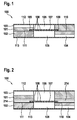
- Fig. 1 shows a schematic sectional view of a processing apparatus 100 or device for processing according to an embodiment of the present invention.
- the processing device 100 is designed to process a sample of biological material containing target cells.
- the sample is a liquid sample which has the target cells and, for example, companion cells and / or accompanying particles.
- the processing device 100 is, for example, part of a microfluidic system, in particular for use in medical diagnostics.
- the processing apparatus 100 is according to the in Fig. 1 illustrated embodiment of the present invention executed in the form of a layer stack.
- the processing apparatus 100 has according to the in Fig. 1 illustrated embodiment of the present invention, a first substrate 101 and a second substrate 102.
- a first microfluidic channel 103 is formed in the first substrate 101.
- the first microfluidic channel 103 is, for example, a supply channel for the sample.
- a second microfluidic channel 104 is formed in the second substrate 102.
- the second microfluidic channel 104 is for example a discharge channel for the sample.
- the first substrate 101 has a first opening 105 or a first cavity.
- the first aperture 105 is formed as a through hole in the first substrate 101.
- the first microfluidic channel 103 opens into the first opening 105.
- the second substrate 102 has a second opening 106 or a second cavity.
- the second opening 106 is formed as a through hole in the second substrate 102.
- the second microfluidic channel 104 opens into the second opening 106.
- the microfluidic channels 103 and 104 and the openings 105 and 106 are designed to guide the sample of biological material.
- the processing apparatus 100 has a membrane 107 having a plurality of pores 108.
- the plurality of pores 108 are configured to filter the target cells from the sample.
- the membrane 107 is formed as a filter membrane of a piezoelectric material.
- the membrane 107 or filter membrane is designed to be mechanically deformed by an applied or applied to the membrane 107 electrical signal.
- the membrane 107 is designed to be set in mechanical vibrations by the electrical signal. The mechanical deformation or the mechanical vibrations of the membrane 107 are suitable for effecting lysis of the target cells.
- the first substrate 101, the second substrate 102 and the membrane 107 are in this case according to the in Fig. 1 shown embodiment of the present invention stacked and interconnected.
- the membrane 107 is arranged between the first substrate 101 and in the second substrate 102.
- the first opening 105 of the first substrate 101 and the second opening 106 of the second substrate 102 are separated by the membrane 107.
- a portion of the diaphragm 107 is disposed between the first aperture 105 and the second aperture 106.
- a first main surface of the membrane 107 adjoins the first opening 105, wherein a second main surface of the membrane 107 adjoins the second opening 106.
- an edge portion of the diaphragm 107 is disposed between a body of the first substrate 101 and a body of the second substrate 102.
- a recess or a receiving portion 109 for receiving the membrane 107, in particular of the edge portion of the membrane 107 is formed in the first substrate 101.
- the edge portion of the diaphragm 107 is disposed in the receiving portion 109.
- the receiving section 109 is formed by a step in a main surface of the first substrate 101 facing the second substrate 102. In this case, the receiving portion 109, the first opening 105 formed around.
- the second substrate 102 may have a further receiving portion.
- the processing device 100 further comprises printed conductors 110 and 111 or electrical conductors.
- the conductor tracks 110 and 111 are electrically conductively connected to the membrane 107.
- the conductor tracks 110 and 111 are arranged between the first substrate 101 and the second substrate 102.
- the conductor tracks 110 and 111 are applied and / or arranged on the second substrate 102.
- the membrane 107 is electrically contacted on the side of the second opening 106 facing the main surface of the membrane 107 by the interconnects 110 and 111.
- the processing apparatus 100 illustrated embodiment of the present invention, a first cover layer 112 and a second cover layer 113 on.
- the first cover layer 112 is applied and / or arranged on a main surface of the first substrate 101 facing away from the second substrate 102.
- the second cover layer 113 is applied and / or arranged on a main surface of the second substrate 102 facing away from the first substrate 101.
- the first microfluidic channel 103 is covered by the first cover layer 112.
- the second microfluidic channel 104 is covered by the second cover layer 113.
- FIG. 1 shows Fig. 1 a cross-section through a processing device 100, which has the two substrates 101 and 102, each with a microfluidic channel 103 and 104 and in each case an opening 105 and 106.
- the filter membrane 107 with piezoelectric properties, which is penetrated by the pores 108, which allow filtration by size exclusion.
- the recess 109 is formed by way of example in the first substrate 101.
- the electrical contacting of the filter membrane 107 takes place via the two conductor tracks 110 and 111, which are applied by way of example to the second substrate 102.
- the microfluidic channels 103 and 104 are capped by the cover layers 112 and 113 to obtain a sealed system.
- suitable adhesives may be used to seal the filter membrane 107.
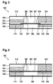
- Fig. 2 shows a schematic sectional view of a processing apparatus 100 according to an embodiment of the present invention.
- processing apparatus 100 corresponds to the processing device Fig. 1 except that the first substrate 101 is formed without a receiving portion and that the processing apparatus 100 in FIG Fig. 2 further comprises a carrier layer 214 in the form of an elastic membrane.
- the carrier layer 214 is disposed between the first substrate 101 and the second substrate 102.
- the carrier layer 214 is an elastic membrane which is inserted between the substrates 101 and 102 and has or has a passage opening in the region of the openings 105 and 106.
- a recess portion in at least one of the substrates 101 and 102 can be dispensed with, since an elasticity of the carrier layer 214 can be selected so that in a joined state of the processing apparatus 100, a height difference between the carrier layer 214 and the membrane 107 can be compensated.
- Fig. 3 shows a schematic sectional view of a processing apparatus 100 according to an embodiment of the present invention.
- processing apparatus 100 corresponds to the processing device Fig. 2 except that in Fig. 3 the membrane 107 is coated on a first main surface with a first electrically conductive layer 316 and on a second main surface with a second electrically conductive layer 317, and that the membrane 107 has a through-contact 318 between the first main surface and the second main surface of the membrane 107.
- the first electrically conductive layer 316 is applied to the membrane 107 on the side of the first opening 105 or of the first substrate 101.
- the second electrically conductive layer 317 is applied to the membrane 107 on the side of the second opening 106 or of the second substrate 102.
- the first electrically conductive layer 316 and the second electrically conductive layer 317 are connected to one another by means of the through contact 318.
- the through-contact 318 serves to be able to contact the upper layer via the conductor 110, but not an electrically conductive connection of the two layers.
- a first conductor 110 of the conductors 110 and 111 is electrically connected to the contact 318.
- the first electrically conductive layer 316 is contacted by the first interconnect 110 via the via 318, wherein the second electrically conductive layer 317 is contacted by a second interconnect 111 of the interconnects 110 and 111.
- the membrane 107 is thus coated on both sides with conductive material.
- the electrically conductive layers 316 and 317 are opened over the pores 108 and electrically contacted such that the conductor tracks 110 and 111 are only in contact with one of the two electrically conductive layers 316 and 317, respectively.
- the through-contact 318 in this case is a filled with conductive material breakthrough through the membrane 107 executed.
- Fig. 4 shows a schematic sectional view of a processing apparatus 100 according to an embodiment of the present invention.
- processing apparatus 100 corresponds to the processing device Fig. 3 except that in Fig. 4 the membrane 107 is designed without through-contact, in other words dispensed with the use of a filled with conductive material breakthrough within the membrane 107, and that the first conductor 110 is applied to the first substrate 101, thereby costs for the membrane 107 can be reduced become.
- the first conductive trace 110 is disposed on the side of a first major surface of the membrane 107.
- the first interconnect 110 is thus arranged to electrically contact the membrane 107 at a main surface of the membrane 107 facing the first aperture 105 and the first substrate 101, respectively.
- the second conductor 111 is arranged on the side of a second main surface of the membrane 107.
- the second interconnect 111 is thus arranged to electrically contact the membrane 107 at a main surface of the membrane 107 facing the second aperture 106 and the second substrate 102, respectively.
- the recessed portion of the support layer 214 is formed here as a through hole.
- FIG. 12 shows a flow chart of a method 500 for manufacturing according to an embodiment of the present invention.
- the method 500 for manufacturing is executable to produce a processing apparatus for processing a sample of biological material containing target cells.
- a processing apparatus is one of FIGS. 1 to 4 or a similar processing device can be produced.
- the method 500 includes a step 510 of forming a diaphragm of a piezoelectric material.
- the membrane formed in step 510 of the molding is designed to be mechanically deformable by an electrical signal in order to effect a lysis of the target cells.
- the method 500 includes a step 520 of forming pores in the formed membrane.
- the pores are formed in step 520 of formation so as to be suitable for filtering the target cells from the sample.
- the pores and possibly other structures within the membrane can be introduced micromechanically, in particular by wet-chemical etching or the like.
- printed conductors can also be applied, for example using screen printing, inkjet printing, molded interconnect devices (MID) technology, in particular by sputtering or vapor deposition.
- layers for forming a layer stack of the processing device can also be joined together, for example using adhesives, laser transmission welding or thermal bonding.
- FIG. 12 shows a flowchart of a method 600 for processing according to an embodiment of the present invention.
- the method 600 for processing is executable to process a sample of biological material containing target cells.
- the method 600 for machining using a machining apparatus such as the machining apparatus is one of FIGS. 1 to 4 executable.
- the method 600 is operable to perform a filtration and lysis of a sample of biological material containing target cells.
- the process 600 for processing includes a step 610 of filtering the target cells from the sample using the membrane having the pores.
- the sample in particular liquid sample, which contains the target cells and whose background is to be removed, are introduced into the processing device via the first microfluidic channel.
- the filtering step 610 may be pressure driven, e.g. B. by integrated in a microfluidic system pumps or external pumps.
- the target cells are retained on the membrane of the processing apparatus and a filter passage material of the sample is transported away via the second microfluidic channel of the processing apparatus.
- a step 620 of application subsequent to step 610 of the filtering, the processing 600 applies an electrical signal to the membrane formed from the piezoelectric material to mechanically deform the membrane so as to cause lysis of the target cells.
- a lysis buffer or liquid which may set a suitable lysing chemical environment, may be added to the target cells filtered out.
- an electrical voltage can be applied to the conductor tracks of the processing device. This results in a mechanical deformation of the membrane due to the piezoelectric effect, which makes it possible to lyse the target cells with the aid of resulting pressure waves or cavitation.
- the processing device 100 represents a layer structure consisting of two substrates 101 and 102, each having a channel 103 and 104 and a respective through-hole or aperture 105 and 106, and arranged between the substrate 101 and 102 piezoelectric layer or membrane 107 which makes electrical contact is.
- the piezoelectric membrane 107 is additionally penetrated by pores 108 whose diameter allows filtration of cells of the sample by size exclusion. In this way, first a sample pressure-driven flushed through the filter 107 represented by the membrane, whereupon the target cells are retained on the piezoelectric filter layer or membrane 107.
- the piezoelectric filter layer or membrane 107 can be mechanically moved or deformed in order to lyse the target cells by the thus caused pressure waves or the cavitation thus caused.
- a single component is provided or used with the membrane 107 in order to perform the functions of filtration and lysis in part-moderately combined.
- Material examples of parts of the processing apparatus 100 include for the substrates 101 and 102, for example, a polymeric material, e.g. As thermoplastic (eg., PC, PP, PE, PMMA, COP, COC) or thermoset, silicon or glass, for the cover layers 112 and 113, for example, silicon, glass, polymer films, in particular adhesive sheets, or the like, for the conductor tracks 110th and 111 and for the electrically conductive layers 316 and 317 and the contact 318, a conductive material, in particular a metal or metals, for. As copper, aluminum, titanium or the like, and for the membrane 107 finally piezoelectric materials, in particular PZT or the like.
- a polymeric material e.g. As thermoplastic (eg., PC, PP, PE, PMMA, COP, COC) or thermoset, silicon or glass, for the cover layers 112 and 113, for example, silicon, glass, polymer films, in particular adhesive sheets, or the like, for the conductor tracks 110th
- Exemplary dimensions for parts of the processing apparatus 100 include for a thickness of the substrates 101 and 102, for example 0.1 to 10 millimeters, for a thickness of the membrane 107, for example 50 micrometers to 1 millimeter, for example, an area of the membrane 107 may be 500 square microns to 100 square millimeters, for example, a diameter of the pores 108 may be 50 nanometers to 10 microns, and for a thickness of the carrier layer 214 may be 100 microns to 2 millimeters.
- Exemplary electrical parameters for driving the piezoelectric filter membrane 107 in step 620 of application in the method 600 for processing include an AC electrical voltage having a frequency of, for example, 1 kilohertz to 10 megahertz and a voltage of, for example, 100 volts to 5000 volts.
- an exemplary embodiment comprises a "and / or" link between a first feature and a second feature, then this is to be read so that the embodiment according to one embodiment, both the first feature and the second feature and according to another embodiment either only first feature or only the second feature.
Abstract
Die Erfindung betrifft eine Vorrichtung (100) zum Bearbeiten einer Zielzellen enthaltenden Probe biologischen Materials. Die Vorrichtung (100) weist eine Membran (107) mit Poren (108) auf. Hierbei sind die Poren (108) ausgebildet, um die Zielzellen aus der Probe zu filtern. Die Membran (107) ist aus einem piezoelektrischen Material ausgeformt. Dabei ist die Membran (107) durch ein elektrisches Signal mechanisch verformbar, um eine Lyse der Zielzellen zu bewirken.The invention relates to a device (100) for processing a sample of biological material containing target cells. The device (100) has a membrane (107) with pores (108). Here, the pores (108) are formed to filter the target cells from the sample. The membrane (107) is formed of a piezoelectric material. In this case, the membrane (107) is mechanically deformable by an electrical signal to cause lysis of the target cells.
Description
Die vorliegende Erfindung bezieht sich auf eine Vorrichtung zum Bearbeiten einer Zielzellen enthaltenden Probe biologischen Materials, auf ein Verfahren zum Herstellen einer Vorrichtung zum Bearbeiten einer Zielzellen enthaltenden Probe biologischen Materials, auf ein Verfahren zum Bearbeiten einer Zielzellen enthaltenden Probe biologischen Materials, auf ein entsprechendes Steuergerät sowie auf ein entsprechendes Computerprogramm.The present invention relates to a device for processing a sample of biological material containing target cells, to a method for producing a device for processing a sample of biological material containing target cells, to a method for processing a sample of biological material containing target cells, to a corresponding control device and to a device to a corresponding computer program.
Mikrofluidische Lab-on-a-Chip-Systeme können häufig beispielsweise aus Mehrschichtaufbauten mit integrierten mikrofluidischen Kanälen, Kavitäten, Ventilen und Filtereinrichtungen bestehen.For example, microfluidic lab-on-a-chip systems can often consist of multi-layered structures with integrated microfluidic channels, cavities, valves, and filtering devices.
Die
Vor diesem Hintergrund werden mit dem hier vorgestellten Ansatz eine Vorrichtung zum Bearbeiten einer Zielzellen enthaltenden Probe biologischen Materials, ein Verfahren zum Herstellen einer Vorrichtung zum Bearbeiten einer Zielzellen enthaltenden Probe biologischen Materials, ein Verfahren zum Bearbeiten einer Zielzellen enthaltenden Probe biologischen Materials, weiterhin ein Steuergerät, das eines dieser Verfahren verwendet, sowie schließlich ein entsprechendes Computerprogramm gemäß den Hauptansprüchen vorgestellt. Vorteilhafte Ausgestaltungen ergeben sich aus den jeweiligen Unteransprüchen und der nachfolgenden Beschreibung.Against this background, with the approach presented here, an apparatus for processing a sample of biological material containing target cells, a method for producing a device for processing a sample of biological material containing target cells, a method for Processing a sample of biological material containing target cells, furthermore a control unit which uses one of these methods, and finally a corresponding computer program according to the main claims. Advantageous embodiments emerge from the respective subclaims and the following description.
Gemäß Ausführungsformen der vorliegenden Erfindung kann insbesondere für mikrofluidische Chiplabor-Systeme bzw. Lab-on-Chip-Systeme zur medizinischen Diagnostik eine funktionale Vereinigung von Filtration und Lyse in einem einzigen mikrofluidischen Bauteil realisiert werden. Somit kann beispielsweise ein einziges Bauteil als kombinierter mikrofluidischer piezoelektromechanischer Filter und Lysator für ein mikrofluidisches Lab-on-Chip-System bereitgestellt und verwendet werden.According to embodiments of the present invention, in particular for microfluidic chip lab systems or lab-on-chip systems for medical diagnostics, a functional combination of filtration and lysis can be realized in a single microfluidic component. Thus, for example, a single component may be provided and used as a combined microfluidic piezo-electromechanical filter and lysator for a lab-on-chip microfluidic system.
Vorteilhafterweise können gemäß Ausführungsformen der vorliegenden Erfindung insbesondere dadurch, dass sowohl Filtration als auch Lyse in einer Kammer und mittels eines Bauteils durchgeführt werden können, hierbei Kosten, Platzbedarf und Komplexität einer mikrofluidischen Verschaltung reduziert werden. Auch kann beispielsweise eine Empfindlichkeit bzw. Sensitivität eines mikrofluidischen Gesamtsystems erhöht werden, da die Probe, insbesondere die Zielzellen, zwischen Filtration und Lyse nicht zwischen zwei Kammern transferiert werden muss und somit kein Probenmaterial auf der Strecke bleibt.Advantageously, according to embodiments of the present invention, in particular the fact that both filtration and lysis can be carried out in a chamber and by means of a component, in this case costs, space requirements and complexity of a microfluidic interconnection can be reduced. It is also possible, for example, to increase a sensitivity or sensitivity of a microfluidic overall system, since the sample, in particular the target cells, does not have to be transferred between two chambers between filtration and lysis and thus no sample material remains on the line.
Es kann gemäß Ausführungsformen der vorliegenden Erfindung ferner insbesondere eine Verwendung eines externen Ultraschallgebers vermieden werden, dessen Einkopplung von einem Kontakt des Ultraschallgebers zu einer Oberfläche des mikrofluidischen Systems abhängig wäre, d. h., es kann ein diesbezüglicher Aufwand für eine Justage entfallen. Da somit beispielsweise mikrofluidische Systeme mit mikrosystemtechnischen Methoden in großen Stückzahlen mit geringen Toleranzen hergestellt werden können, so können eine Reproduzierbarkeit und eine Ausbeute bei der Lyse von Zellen erhöht werden, wodurch wiederum eine Sensitivität des Gesamtsystems gesteigert werden kann. Zusätzlich können Kosten für eine ansonsten erforderliche externe Ansteuerungseinheit reduziert werden, da auf einen externen Ultraschallgeber und eine zugehörige Mechanik verzichtet werden kann. Zudem kann eine mechanische Belastung eines mikrofluidischen Systems gesenkt werden, da anders als bei einer Verwendung eines externen Ultraschallgebers, bei dem sich der Ultraschall über die Wände der Lysekammer hinaus ausbreiten kann, eine lokale und gezielte Einbringung von Energie einfach erreicht werden kann. Somit kann eine Ultraschallenergie auf gezielte Weise lediglich dort eingekoppelt werden, wo sie tatsächlich benötigt wird. Hierdurch kann eine mechanische Belastung reduziert und eine Robustheit des Gesamtsystems erhöht werden. Anders als bei enzymatischen Ansätzen zur Lyse kann auf zusätzliche Reagenzien verzichtet werden, wodurch Kosten gespart werden können und eine Komplexität einer mikrofluidischen Verschaltung reduziert werden kann. Im Gegensatz zu thermischen Ansätzen zur Lyse kann auf eine Ankopplung bzw. Einbringung eines Heizelements verzichtet werden, wobei die Lyse auch beispielsweise bei Raumtemperatur durchgeführt werden kann. Dies kann eine Extraktion von Proteinen ermöglichen, welche bei einer thermischen Lyse denaturiert werden würden.Furthermore, according to embodiments of the present invention, in particular a use of an external ultrasound transmitter can be avoided, the coupling of which would depend on a contact of the ultrasound transmitter with a surface of the microfluidic system, ie, a corresponding outlay for an adjustment can be dispensed with. Thus, for example, microfluidic systems can be manufactured in large quantities with low tolerances using microsystem technology methods, so that reproducibility and a yield in the lysis of cells can be increased, which in turn can increase the sensitivity of the overall system. In addition, costs for an otherwise required external drive unit can be reduced, as can be dispensed with an external ultrasonic transducer and associated mechanics. In addition, one can mechanical stress on a microfluidic system can be reduced since, unlike using an external ultrasound transducer, where the ultrasound can propagate beyond the walls of the lysis chamber, local and targeted introduction of energy can be easily achieved. Thus, an ultrasonic energy can be coupled in a targeted manner only where it is actually needed. As a result, a mechanical load can be reduced and a robustness of the overall system can be increased. Unlike enzymatic approaches to lysis, additional reagents can be dispensed with, which can save costs and reduce the complexity of microfluidic circuitry. In contrast to thermal approaches to lysis can be dispensed with a coupling or insertion of a heating element, the lysis can also be carried out, for example, at room temperature. This may allow for extraction of proteins that would be denatured on thermal lysis.
Es wird eine Vorrichtung zum Bearbeiten einer Zielzellen enthaltenden Probe biologischen Materials vorgestellt, wobei die Vorrichtung folgende Merkmale aufweist:
- eine Membran mit Poren, wobei die Poren ausgebildet sind, um die Zielzellen aus der Probe zu filtern, wobei die Membran aus einem piezoelektrischen Material ausgeformt ist, wobei die Membran durch ein elektrisches Signal mechanisch verformbar ist, um eine Lyse der Zielzellen zu bewirken.
- a membrane having pores, wherein the pores are configured to filter the target cells from the sample, the membrane being formed of a piezoelectric material, the membrane being mechanically deformable by an electrical signal to cause lysis of the target cells.
Bei der Vorrichtung kann es sich um ein mikrofluidisches System oder einen Teil eines mikrofluidischen Systems handeln, insbesondere um ein sogenanntes Chiplabor-System oder Chiplabor, das auch als Lab-on-Chip-System bezeichnet werden kann. Somit kann ein mikrofluidisches System die Vorrichtung aufweisen. Das piezoelektrische Material kann beispielsweise ein piezoelektrisches Keramikmaterial aufweisen, insbesondere Blei-Zirkonat-Titanat (PZT), ein Stoffverbund aus Blei (Pb), Sauerstoff (O) und Titan (Ti) oder Zirconium (Zr). Die Probe kann eine flüssige Probe sein. Die Vorrichtung kann ausgebildet sein, um die Probe an die Membran und zusätzlich oder alternativ durch die Membran zu spülen. Jede Pore der Membran kann eine Abmessung aufweisen, die minimal 10 % der Abmessungen einer einzelnen Zielzelle und einer Abmessung einer Begleitzelle und zusätzlich oder alternativ eines Begleitpartikels der Probe liegt. Die Membran kann ausgebildet sein, um durch das elektrische Signal in mechanische Schwingungen versetzbar zu sein. Bei dem elektrischen Signal kann es sich um ein elektrisches Wechselsignal handeln.The device can be a microfluidic system or a part of a microfluidic system, in particular a so-called chip laboratory system or chip laboratory, which can also be referred to as a lab-on-chip system. Thus, a microfluidic system may comprise the device. The piezoelectric material may comprise, for example, a piezoelectric ceramic material, in particular lead zirconate titanate (PZT), a composite of lead (Pb), oxygen (O) and titanium (Ti) or zirconium (Zr). The sample can be a liquid sample. The device may be configured to flush the sample to the membrane and additionally or alternatively through the membrane. Each pore of the membrane may have a dimension that is minimal 10% of the dimensions of a single target cell and a dimension of a companion cell and additionally or alternatively an accompanying particle of the sample. The membrane can be designed to be displaceable by the electrical signal into mechanical vibrations. The electrical signal may be an electrical alternating signal.
Gemäß einer Ausführungsform kann die Membran zumindest an einer ersten Hauptoberfläche mit einer ersten elektrisch leitfähigen Schicht und an einer zweiten Hauptoberfläche mit einer zweiten elektrisch leitfähigen Schicht beschichtet sein. Eine solche Ausführungsform bietet den Vorteil, dass ein elektrisches Feld im Wesentlichen normal zu einer Hauptoberfläche der Membran angelegt werden kann, wodurch eine mechanische Auslenkung der Membran normal zur Oberfläche begrenzt werden kann. Hierdurch kann eine Belastung an Befestigungspunkten der Membran gesenkt und eine Robustheit der Vorrichtung erhöht werden. Auch kann ein direkter Kontakt zwischen der Probe und einer Oberfläche der Membran vermieden werden und damit eine Freisetzung von Inhibitoren für biochemische Reaktionen verhindert werden.According to one embodiment, the membrane may be coated on at least one first main surface with a first electrically conductive layer and on a second main surface with a second electrically conductive layer. Such an embodiment offers the advantage that an electric field can be applied substantially normal to a major surface of the membrane, whereby a mechanical deflection of the membrane normal to the surface can be limited. In this way, a load on attachment points of the membrane can be lowered and a robustness of the device can be increased. Also, direct contact between the sample and a surface of the membrane can be avoided, thus preventing the release of inhibitors of biochemical reactions.
Auch kann die Vorrichtung elektrische Leiter zum elektrischen Kontaktieren der Membran aufweisen. Hierbei kann ein erster elektrischer Leiter auf Seiten einer ersten Hauptoberfläche der Membran angeordnet sein und kann ein zweiter elektrischer Leiter auf Seiten einer zweiten Hauptoberfläche der Membran angeordnet sein. Die erste Hauptoberfläche und die zweite Hauptoberfläche der Membran können voneinander abgewandt sein. Eine solche Ausführungsform bietet den Vorteil, dass eine Ankontaktierung der Membran zur mechanischen Verformung durch das elektrische Signal auf einfache und unaufwendige Weise realisiert werden können.Also, the device may comprise electrical conductors for electrically contacting the membrane. In this case, a first electrical conductor can be arranged on the side of a first main surface of the membrane, and a second electrical conductor can be arranged on the side of a second main surface of the membrane. The first main surface and the second main surface of the membrane may face away from each other. Such an embodiment offers the advantage that a contacting of the membrane for mechanical deformation by the electrical signal can be realized in a simple and inexpensive manner.
Alternativ kann die Vorrichtung elektrische Leiter zum elektrischen Kontaktieren der Membran aufweisen. Hierbei können die elektrischen Leiter auf Seiten einer ersten Hauptoberfläche der Membran angeordnet sein. Dabei kann die Membran einen Durchkontakt zwischen der ersten Hauptoberfläche und einer zweiten Hauptoberfläche der Membran aufweisen, wobei einer der elektrischen Leiter an dem Durchkontakt angeschlossen sein kann. Die erste Hauptoberfläche und die zweite Hauptoberfläche der Membran können voneinander abgewandt sein. Der eine der elektrischen Leiter kann elektrisch leitfähig mit dem Durchkontakt verbunden sein. Eine solche Ausführungsform bietet den Vorteil, dass lediglich auf einer Seite der Membran elektrische Leiter vorgesehen sein brauchen, wobei ein Aufbau der Vorrichtung vereinfacht werden kann.Alternatively, the device may comprise electrical conductors for electrically contacting the membrane. In this case, the electrical conductors can be arranged on the side of a first main surface of the membrane. In this case, the membrane may have a through contact between the first main surface and a second main surface of the membrane, wherein one of the electrical conductors may be connected to the via. The first main surface and the second main surface of the membrane may face away from each other. Of the one of the electrical conductors may be electrically conductively connected to the via. Such an embodiment offers the advantage that only on one side of the membrane electrical conductors need to be provided, wherein a structure of the device can be simplified.
Ferner kann die Vorrichtung eine Trägerschicht mit einem Aussparungsabschnitt zum Aufnehmen der Membran aufweisen. Hierbei kann die Membran in dem Aussparungsabschnitt der Trägerschicht angeordnet sein. Die Trägerschicht kann aus einem elastischen Material ausgeformt sein. Der Aussparungsabschnitt kann durch einen Vertiefungsabschnitt oder ein Durchgangsloch ausgeformt sein. Eine solche Ausführungsform bietet den Vorteil, dass die Membran vor mechanischer Belastung geschützt sowie sicher in Position gehalten unterbringbar ist. Ferner kann im Falle eines Schichtstapelaufbaus der Vorrichtung die Trägerschicht als eine Zwischenlage mit Schutzfunktion, Dichtfunktion und/oder Positionierfunktion fungieren.Further, the device may comprise a carrier layer having a recess portion for receiving the membrane. In this case, the membrane may be arranged in the recess section of the carrier layer. The carrier layer may be formed of an elastic material. The recess portion may be formed by a recessed portion or a through hole. Such an embodiment has the advantage that the membrane is protected against mechanical stress and securely held in position can be accommodated. Furthermore, in the case of a layered stack construction of the device, the carrier layer may function as an intermediate layer with protective function, sealing function and / or positioning function.
Gemäß einer Ausführungsform kann die Vorrichtung ein erstes Substrat mit einer ersten Kavität, ein zweites Substrat mit einer zweiten Kavität und elektrische Leiter zum elektrischen Kontaktieren der Membran aufweisen. Hierbei können die Substrate zusammengefügt sein. Dabei können die Membran und die elektrischen Leiter zwischen den Substraten angeordnet sein. Hierbei können mittels der Membran die Kavitäten voneinander abgetrennt sein. Somit können die Substrate aneinandergefügt sein. Anders ausgedrückt können die Substrate mittels einer Fügeverbindung miteinander verbunden sein. Dabei können die Substrate aufeinandergestapelt angeordnet und miteinander verbunden sein. Mittels der Membran können die Kavitäten teilweise fluidisch voneinander abgetrennt sein, wobei die Membran für Partikel mit einer Abmessung bis zu einem Durchmesser einer Pore der Membran permeabel sein kann. Eine solche Ausführungsform bietet den Vorteil, dass ein unaufwendiger und stabiler Schichtaufbau bzw. Schichtstapel bereitgestellt werden kann, in dem die Membran anordenbar oder angeordnet ist.In one embodiment, the device may include a first substrate having a first cavity, a second substrate having a second cavity, and electrical conductors for electrically contacting the membrane. In this case, the substrates can be joined together. In this case, the membrane and the electrical conductors can be arranged between the substrates. In this case, the cavities can be separated from one another by means of the membrane. Thus, the substrates may be joined together. In other words, the substrates can be connected to each other by means of a joint connection. In this case, the substrates can be stacked and interconnected. By means of the membrane, the cavities can be partly separated from each other fluidically, wherein the membrane can be permeable to particles with a dimension up to a diameter of a pore of the membrane. Such an embodiment offers the advantage that an inexpensive and stable layer structure or layer stack can be provided, in which the membrane can be arranged or arranged.
Dabei kann zumindest eines der Substrate einen Aufnahmeabschnitt zum Aufnehmen der Membran aufweisen. Hierbei kann die Membran in dem Aufnahmeabschnitt angeordnet sein. Insbesondere kann eine Fügefläche, an der ein Substrat mit dem anderen Substrat zusammenfügbar ist, um einen Bereich der Kavität herum ein gestuftes Profil und zusätzlich oder alternativ einen Vertiefungsabschnitt aufweisen. Eine solche Ausführungsform bietet den Vorteil, dass die Membran in Zwischenlage zwischen den Substraten optional auch ohne eine Trägerschicht sicher gehalten sein kann.In this case, at least one of the substrates may have a receiving portion for receiving the membrane. In this case, the membrane may be arranged in the receiving portion. In particular, a joint surface on the one substrate is attachable to the other substrate, having a stepped profile around a portion of the cavity, and additionally or alternatively a recess portion. Such an embodiment offers the advantage that the membrane in the intermediate position between the substrates can optionally be held securely even without a carrier layer.
Es wird auch ein Verfahren zum Herstellen einer Vorrichtung zum Bearbeiten einer Zielzellen enthaltenden Probe biologischen Materials vorgestellt, wobei das Verfahren folgende Schritte aufweist:There is also provided a method of manufacturing a device for processing a sample of biological material containing target cells, the method comprising the steps of:
Ausformen einer Membran aus einem piezoelektrischen Material, wobei die Membran durch ein elektrisches Signal mechanisch verformbar ist, um eine Lyse der Zielzellen zu bewirken; undForming a membrane from a piezoelectric material, wherein the membrane is mechanically deformable by an electrical signal to cause lysis of the target cells; and
Ausbilden von Poren, die zum Filtern der Zielzellen aus der Probe geeignet sind, in der Membran.Forming pores suitable for filtering the target cells from the sample in the membrane.
Durch Ausführen des Verfahrens zum Herstellen kann eine Ausführungsform der vorstehend genannten Vorrichtung zum Bearbeiten vorteilhaft hergestellt werden.By carrying out the method of manufacturing, an embodiment of the above-mentioned apparatus for working can be advantageously produced.
Es wird ferner ein Verfahren zum Bearbeiten einer Zielzellen enthaltenden Probe biologischen Materials, wobei das Verfahren in Verbindung mit einer Ausführungsform der vorstehend genannten Vorrichtung ausführbar ist, wobei das Verfahren folgende Schritte aufweist:There is further provided a method of processing a sample of biological material containing target cells, the method being practicable in conjunction with an embodiment of the aforementioned device, the method comprising the steps of:
Filtern der Zielzellen aus der Probe unter Verwendung der Membran mit den Poren; undFiltering the target cells from the sample using the membrane with the pores; and
Anlegen eines elektrischen Signals an die aus dem piezoelektrischen Material ausgeformte Membran, um die Membran mechanisch zu verformen, um eine Lyse der Zielzellen zu bewirken.Applying an electrical signal to the membrane formed from the piezoelectric material to mechanically deform the membrane to cause lysis of the target cells.
Das Verfahren zum Bearbeiten kann in Verbindung mit einer Ausführungsform der vorstehend genannten Vorrichtung zum Bearbeiten vorteilhaft ausgeführt werden. Im Schritt des Anlegens kann als das elektrische Signal eine elektrische Wechselspannung an die Membran angelegt werden.The method of processing may be advantageously carried out in connection with an embodiment of the aforementioned apparatus for processing become. In the step of applying, an electrical AC voltage may be applied to the diaphragm as the electrical signal.
Der hier vorgestellte Ansatz schafft ferner ein Steuergerät, das ausgebildet ist, um die Schritte einer Variante eines hier vorgestellten Verfahrens in entsprechenden Einrichtungen durchzuführen, anzusteuern bzw. umzusetzen. Auch durch diese Ausführungsvariante der Erfindung in Form eines Steuergeräts kann die der Erfindung zugrunde liegende Aufgabe schnell und effizient gelöst werden.The approach presented here also creates a control unit which is designed to execute, to control or to implement the steps of a variant of a method presented here in corresponding devices. Also by this embodiment of the invention in the form of a control device, the object underlying the invention can be achieved quickly and efficiently.
Unter einem Steuergerät kann vorliegend ein elektrisches Gerät verstanden werden, das Sensorsignale verarbeitet und in Abhängigkeit davon Steuer- und/oder Datensignale ausgibt. Das Steuergerät kann eine Schnittstelle aufweisen, die hard- und/oder softwaremäßig ausgebildet sein kann. Bei einer hardwaremäßigen Ausbildung können die Schnittstellen beispielsweise Teil eines sogenannten System-ASICs sein, der verschiedenste Funktionen des Steuergeräts beinhaltet. Es ist jedoch auch möglich, dass die Schnittstellen eigene, integrierte Schaltkreise sind oder zumindest teilweise aus diskreten Bauelementen bestehen. Bei einer softwaremäßigen Ausbildung können die Schnittstellen Softwaremodule sein, die beispielsweise auf einem Mikrocontroller neben anderen Softwaremodulen vorhanden sind.In the present case, a control device can be understood as meaning an electrical device which processes sensor signals and outputs control and / or data signals in dependence thereon. The control unit may have an interface, which may be formed in hardware and / or software. In the case of a hardware-based design, the interfaces can be part of a so-called system ASIC, for example, which contains various functions of the control unit. However, it is also possible that the interfaces are their own integrated circuits or at least partially consist of discrete components. In a software training, the interfaces may be software modules that are present, for example, on a microcontroller in addition to other software modules.
Von Vorteil ist auch ein Computerprogrammprodukt oder Computerprogramm mit Programmcode, der auf einem maschinenlesbaren Träger oder Speichermedium wie einem Halbleiterspeicher, einem Festplattenspeicher oder einem optischen Speicher gespeichert sein kann und zur Durchführung, Umsetzung und/oder Ansteuerung der Schritte des Verfahrens nach einer der vorstehend beschriebenen Ausführungsformen verwendet wird, insbesondere wenn das Programmprodukt oder Programm auf einem Computer oder einem Steuergerät ausgeführt wird.Also of advantage is a computer program product or computer program with program code which can be stored on a machine-readable carrier or storage medium such as a semiconductor memory, a hard disk memory or an optical memory and for carrying out, implementing and / or controlling the steps of the method according to one of the embodiments described above is used, especially when the program product or program is executed on a computer or a controller.
Der hier vorgestellte Ansatz wird nachstehend anhand der beigefügten Zeichnungen beispielhaft näher erläutert. Es zeigen:
-
Fig. 1 eine schematische Schnittdarstellung einer Vorrichtung zum Bearbeiten gemäß einem Ausführungsbeispiel der vorliegenden Erfindung; -
Fig. 2 eine schematische Schnittdarstellung einer Vorrichtung zum Bearbeiten gemäß einem weiteren Ausführungsbeispiel der vorliegenden Erfindung; -
Fig. 3 eine schematische Schnittdarstellung einer Vorrichtung zum Bearbeiten gemäß einem weiteren Ausführungsbeispiel der vorliegenden Erfindung; -
Fig. 4 eine schematische Schnittdarstellung einer Vorrichtung zum Bearbeiten gemäß einem weiteren Ausführungsbeispiel der vorliegenden Erfindung; -
Fig. 5 ein Ablaufdiagramm eines Verfahrens zum Herstellen gemäß einem Ausführungsbeispiel der vorliegenden Erfindung; und -
Fig. 6 ein Ablaufdiagramm eines Verfahrens zum Bearbeiten gemäß einem Ausführungsbeispiel der vorliegenden Erfindung.
-
Fig. 1 a schematic sectional view of an apparatus for processing according to an embodiment of the present invention; -
Fig. 2 a schematic sectional view of an apparatus for processing according to another embodiment of the present invention; -
Fig. 3 a schematic sectional view of an apparatus for processing according to another embodiment of the present invention; -
Fig. 4 a schematic sectional view of an apparatus for processing according to another embodiment of the present invention; -
Fig. 5 a flowchart of a method of manufacturing according to an embodiment of the present invention; and -
Fig. 6 a flowchart of a method for processing according to an embodiment of the present invention.
In der nachfolgenden Beschreibung günstiger Ausführungsbeispiele der vorliegenden Erfindung werden für die in den verschiedenen Figuren dargestellten und ähnlich wirkenden Elemente gleiche oder ähnliche Bezugszeichen verwendet, wobei auf eine wiederholte Beschreibung dieser Elemente verzichtet wird.In the following description of favorable embodiments of the present invention, the same or similar reference numerals are used for the elements shown in the various figures and similar acting, with a repeated description of these elements is omitted.
Bevor Ausführungsbeispiele der vorliegenden Erfindung unter Bezugnahme auf die
Mikrofluidische Lab-on-a-Chip-Systeme bestehen beispielsweise häufig aus Mehrschichtaufbauten mit integrierten mikrofluidischen Kanälen, Kavitäten, Ventilen und Filtereinrichtungen. Hierdurch wird es beispielsweise ermöglicht, konventionelle diagnostische Assays zu integrieren und automatisiert ablaufen zu lassen, wodurch sich Zeitvorteile und Kostenvorteile ergeben können. Zu zentralen Schritten bei einer Aufbereitung einer Patientenprobe, wie zum Beispiel Blut, Urin oder Sputum, zum Nachweis von Zellen, beispielsweise Bakterien oder zirkulierenden Tumorzellen, gehört eine Isolation der Zellen aus der Probe, um störende Restbestandteile zu entfernen, und ein anschließendes Lysieren der Zellen, d. h. ein Öffnen einer Zellmembran, um darin befindliche Bestandteile, wie z. B. DNA oder Proteine, freizusetzen, um deren eindeutige Identifizierung zu ermöglichen.For example, microfluidic lab-on-a-chip systems often consist of multi-layered structures with integrated microfluidic channels, cavities, valves and filter devices. This makes it possible, for example, to integrate conventional diagnostic assays and run them automatically, which can result in time advantages and cost advantages. At central steps in the preparation of a patient sample, such as Blood, urine or sputum, for detection of cells, for example bacteria or circulating tumor cells, includes isolation of the cells from the sample to remove interfering residual components and subsequent lysing of the cells, ie opening of a cell membrane to constituents therein, such as As DNA or proteins, to enable their unique identification.
Zur Isolation der Zellen sind verschiedene Prinzipien üblich. Bei einer mechanischen Filtrierung durch Größenausschluss werden Filtermaterialien eingesetzt, deren Porendurchmesser groß genug ist, um andere Bestandteile der Probe durchzuleiten, jedoch klein genug, um die Zielzellen zurückzuhalten. Bei einer Zentrifugation wird, makroskopisch und mikrofluidisch betrachtet, eine unterschiedliche Dichte von Zielzellen zur Umgebung ausgenutzt, um durch Beschleunigungskräfte Zellen zu separieren. Bei einer hydrodynamischen Trennung können, mikrofluidisch betrachtet, hydrodynamische Kräfte, welche insbesondere in mikrofluidischen Kanälen auftreten, genutzt werden, um Zellen zu isolieren. Bei einer Verwendung akustischer Filter können, mikrofluidisch betrachtet, stehende Wellen eingesetzt werden, um Partikel innerhalb von Wellenbäuchen oder Wellenknoten zu sammeln und mit Hilfe eines überlagerten Flusses in verschiedene Kanäle zu leiten.To isolate the cells, various principles are common. Mechanical size-exclusion filtration uses filter materials whose pore diameter is large enough to pass other components of the sample but small enough to retain the target cells. In a centrifugation, macroscopic and microfluidic view, a different density of target cells is used to environment to separate by acceleration forces cells. In a hydrodynamic separation, hydrodynamic forces, which occur in particular in microfluidic channels, can be used, in microfluidic terms, to isolate cells. When acoustic filters are used, microfluidic standing waves can be used to collect particles within shaft tails or wave nodes and guide them into different channels with the aid of a superimposed flow.
Für eine Lyse der Zellen sind verschiedene Prinzipien üblich. Bei einer thermischen Lyse zerreißt, makroskopisch und mikrofluidisch betrachtet, ab einer gewissen Temperatur, beispielsweise im Bereich von 100 Grad Celsius, die Zellmembran. Bei einer enzymatischen Lyse können makroskopisch und mikrofluidisch betrachtet Substanzen eingesetzt werden, welche die Zellmembran mit Hilfe einer chemischen Reaktion zersetzen. Bei einer Lyse mittels Ultraschall kann, mikrofluidisch betrachtet und unter Verwendung eines externen Ultraschallgebers, die Probe bzw. Flüssigkeit mit den intakten Zielzellen in einer Kavität innerhalb eines mikrofluidischen Systems vorgehalten werden, an welches von außen eine Ultraschallsonotrode in Kontakt gebracht wird. Über eine Wand der Kavität wird dann mit Hilfe der Sonotrode Ultraschallenergie in die Probe bzw. Flüssigkeit eingebracht. Damit einhergehende Druckwellen führen dazu bzw. der Effekt der Kavitation führt dazu, dass die Zielzellen lysiert werden. Bei einer Lyse mittels Ultraschall kann, mikrofluidisch betrachtet und unter Verwendung eines integrierten Ultraschallgebers, ein ähnliches Grundprinzip wie vorstehend zum Einsatz kommen, jedoch mit einem in das mikrofluidische System integrierten Ultraschallgeber, beispielsweise in Form einer Schicht aus Blei-Zirkonat-Titanat (PZT).Different principles are common for lysis of the cells. In a thermal lysis tears, macroscopically and microfluidically considered, from a certain temperature, for example in the range of 100 degrees Celsius, the cell membrane. In an enzymatic lysis, macroscopically and microfluidically considered substances can be used which decompose the cell membrane by means of a chemical reaction. When ultrasonically lysed, microfluidically, and using an external ultrasound transducer, the sample or fluid containing the intact target cells can be held in a cavity within a microfluidic system to which an ultrasound sonotrode is brought into contact from the outside. Ultrasonic energy is then introduced into the sample or liquid via a wall of the cavity using the sonotrode. Accompanying pressure waves lead to this or the effect of cavitation leads to the fact that the target cells are lysed. In a lysis by ultrasound, microfluidic considered and under Using a built-in ultrasonic transducer, a similar basic principle as used above, but with an integrated into the microfluidic system ultrasonic transducer, for example in the form of a layer of lead zirconate titanate (PZT).
Die Bearbeitungsvorrichtung 100 weist gemäß dem in
Auch weist die Bearbeitungsvorrichtung 100 eine Membran 107 mit einer Mehrzahl von Poren 108 auf. Aus Platzgründen ist in der Darstellung lediglich eine Teilmenge der Poren 108 mit Bezugszeichen versehen. Die Mehrzahl von Poren 108 ist ausgebildet, um die Zielzellen aus der Probe zu filtern. Die Membran 107 ist als eine Filtermembran aus einem piezoelektrischen Material ausgeformt. Dabei ist die Membran 107 bzw. Filtermembran ausgebildet, um durch ein an die Membran 107 angelegtes oder anlegbares elektrisches Signal mechanisch verformt zu werden. Insbesondere ist die Membran 107 ausgebildet, um durch das elektrische Signal in mechanische Schwingungen versetzt zu werden. Die mechanische Verformung ist bzw. die mechanischen Schwingungen der Membran 107 sind geeignet, um eine Lyse der Zielzellen zu bewirken.Also, the
Das erste Substrat 101, das zweite Substrat 102 und die Membran 107 sind hierbei gemäß dem in
Gemäß dem in
Gemäß einem anderen Ausführungsbeispiel kann zusätzlich oder alternativ das zweite Substrat 102 einen weiteren Aufnahmeabschnitt aufweisen.According to another embodiment, additionally or alternatively, the
Zum elektrischen Kontaktieren der Membran 107 weist die Bearbeitungsvorrichtung 100 ferner Leiterbahnen 110 und 111 bzw. elektrische Leiter auf. Die Leiterbahnen 110 und 111 sind elektrisch leitfähig mit der Membran 107 verbunden. Dabei sind die Leiterbahnen 110 und 111 zwischen dem ersten Substrat 101 und dem zweiten Substrat 102 angeordnet. Gemäß dem in
Zusätzlich weist die Bearbeitungsvorrichtung 100 gemäß dem in
Anders ausgedrückt zeigt
Anders ausgedrückt handelt es sich bei der Trägerschicht 214 um eine elastische Membran, welche zwischen den Substraten 101 und 102 eingefügt ist und im Bereich der Durchbrüche 105 und 106 eine Durchgangsöffnung aufweist bzw. geöffnet ist. Somit kann auf einen Aussparungsabschnitt in mindestens einem der Substrate 101 und 102 verzichtet werden, da eine Elastizität der Trägerschicht 214 so gewählt sein kann, dass in einem zusammengefügten Zustand der Bearbeitungsvorrichtung 100 eine Höhendifferenz zwischen der Trägerschicht 214 und der Membran 107 kompensiert werden kann. Hierdurch kann auch auf einen Einsatz von Klebstoffen im Randabschnitt der Membran 107 verzichtet werden.In other words, the
Die erste elektrisch leitfähige Schicht 316 ist auf Seiten des ersten Durchbruchs 105 bzw. des ersten Substrats 101 auf die Membran 107 aufgebracht. Die zweite elektrisch leitfähige Schicht 317 ist auf Seiten des zweiten Durchbruchs 106 bzw. des zweiten Substrats 102 auf die Membran 107 aufgebracht. Die erste elektrisch leitfähige Schicht 316 und die zweite elektrisch leitfähige Schicht 317 sind mittels des Durchkontakts 318 miteinander verbunden. Der Durchkontakt 318 dient dabei dazu, die obere Schicht über die Leiterbahn 110 kontaktieren zu können, jedoch nicht einer elektrisch leitfähigen Verbinnung der beiden Schichten .Dabei ist beispielhaft eine erste Leiterbahn 110 der Leiterbahnen 110 und 111 an dem Durchkontakt 318 elektrisch angeschlossen. Somit ist die erste elektrisch leitfähige Schicht 316 durch die erste Leiterbahn 110 über den Durchkontakt 318 kontaktiert, wobei die zweite elektrisch leitfähige Schicht 317 durch eine zweite Leiterbahn 111 der Leiterbahnen 110 und 111 kontaktiert ist.The first electrically
Die Membran 107 ist somit beidseitig mit leitfähigem Material beschichtet. Die elektrisch leitfähigen Schichten 316 und 317 sind dabei über den Poren 108 geöffnet und der Art elektrisch kontaktiert, dass die Leiterbahnen 110 und 111 lediglich jeweils zu einer der beiden elektrisch leitfähigen Schichten 316 und 317 in Kontakt sind. Der Durchkontakt 318 ist hierbei ein mit leitfähigem Material gefüllter Durchbruch durch die Membran 107 ausgeführt.The
Somit ist die erste Leiterbahn 110 auf Seiten einer ersten Hauptoberfläche der Membran 107 angeordnet. Die erste Leiterbahn 110 ist somit angeordnet, um die Membran 107 an einer dem ersten Durchbruch 105 bzw. dem ersten Substrat 101 zugewandten Hauptoberfläche der Membran 107 elektrisch zu kontaktieren.Thus, the first
Die zweite Leiterbahn 111 ist auf Seiten einer zweiten Hauptoberfläche der Membran 107 angeordnet. Die zweite Leiterbahn 111 ist somit angeordnet, um die Membran 107 an einer dem zweiten Durchbruch 106 bzw. dem zweiten Substrat 102 zugewandten Hauptoberfläche der Membran 107 elektrisch zu kontaktieren. Der Aussparungsabschnitt der Trägerschicht 214 ist hierbei als eine Durchgangsöffnung ausgeformt.The
Das Verfahren 500 weist einen Schritt 510 des Ausformens einer Membran aus einem piezoelektrischen Material auf. Dabei ist die im Schritt 510 des Ausformens ausgeformte Membran ausgebildet, um durch ein elektrisches Signal mechanisch verformbar zu sein, um eine Lyse der Zielzellen zu bewirken.The
Auch weist das Verfahren 500 einen Schritt 520 des Ausbildens von Poren in der ausgeformten Membran auf. Dabei werden die Poren im Schritt 520 des Ausbildens so ausgebildet, dass sie zum Filtern der Zielzellen aus der Probe geeignet sind. Die Poren und gegebenenfalls andere Strukturen innerhalb der Membran können mikromechanisch eingebracht werden, insbesondere durch nasschemisches Ätzen oder dergleichen.Also, the
Gemäß einem Ausführungsbeispiel können bei dem Verfahren 500 auch Leiterbahnen beispielsweise unter Verwendung von Siebdruck, Inkjet-Printing, Moulded Interconnect Devices Technologie (MID-Technologie), insbesondere durch Sputtern oder Aufdampfen, aufgebracht werden. Ferner können bei dem Verfahren 500 zudem Schichten zum Ausbilden eines Schichtstapels der Bearbeitungsvorrichtung beispielsweise unter Verwendung von Klebstoffen, Laserdurchstrahlschweißen oder thermischem Bonden miteinander gefügt werden.According to one exemplary embodiment, in the
Das Verfahren 600 zum Bearbeiten weist einen Schritt 610 des Filterns der Zielzellen aus der Probe unter Verwendung der Membran mit den Poren auf. Dazu kann bei dem Verfahren 600 zum Bearbeiten die Probe, insbesondere flüssige Probe, welche die Zielzellen enthält und deren Hintergrund entfernt werden soll, über den ersten mikrofluidischen Kanal in die Bearbeitungsvorrichtung eingebracht werden. Der Schritt 610 des Filterns kann beispielsweise druckgetrieben erfolgen, z. B. durch in ein mikrofluidisches System integrierte Pumpen oder externe Pumpen. Im Schritt 610 des Filterns werden die Zielzellen auf der Membran der Bearbeitungsvorrichtung zurückgehalten und wird ein Filterdurchgangsmaterial der Probe über den zweiten mikrofluidischen Kanal der Bearbeitungsvorrichtung abtransportiert.The
In einem bezüglich des Schrittes 610 des Filterns nachfolgend ausführbaren Schritt 620 des Anlegens wird bei dem Verfahren 600 zum Bearbeiten ein elektrisches Signal an die aus dem piezoelektrischen Material ausgeformte Membran angelegt, um die Membran mechanisch zu verformen, um so eine Lyse der Zielzellen zu bewirken. Für den Schritt 620 kann ein Lysepuffer bzw. eine Flüssigkeit, welche eine geeignete chemische Umgebung für die Lyse einstellen kann, zu den herausgefilterten Zielzellen zugegeben werden. Im Schritt 620 des Anlegens kann eine elektrische Spannung an die Leiterbahnen der Bearbeitungsvorrichtung angelegt werden. Hierdurch kommt es aufgrund des piezoelektrischen Effekts zu einer mechanischen Deformation der Membran, welche es ermöglicht, mit Hilfe entstehender Druckwellen bzw. Kavitation die Zielzellen zu lysieren.In a
Unter Bezugnahme auf die
Die Bearbeitungsvorrichtung 100 repräsentiert einen Schichtaufbau bestehend aus zwei Substraten 101 und 102 mit jeweils einem Kanal 103 und 104 und jeweils einem Durchloch bzw. Durchbruch 105 und 106, sowie einer zwischen den Substrat 101 und 102 angeordneten piezoelektrischen Schicht bzw. Membran 107, die elektrisch kontaktiert ist. Die piezoelektrische Membran 107 ist zusätzlich durchsetzt von Poren 108, deren Durchmesser eine Filtrierung von Zellen der Probe durch Größenausschluss ermöglicht. Auf diese Weise kann zunächst eine Probe druckgetrieben durch den durch die Membran 107 repräsentierten Filter gespült werden, woraufhin die Zielzellen auf der piezoelektrischen Filterschicht bzw. Membran 107 zurückgehalten werden. Nachfolgend kann durch Einbringung eines geeigneten elektrischen Signals die piezoelektrische Filterschicht bzw. Membran 107 mechanisch bewegt bzw. verformt werden, um die Zielzellen durch die so bewirkten Druckwellen bzw. die so bewirkte Kavitation zu lysieren. Hierbei wird mit der Membran 107 ein einzelnes Bauteil bereitgestellt oder verwendet, um die Funktionen der Filtrierung und Lyse teilemäßig kombiniert durchzuführen.The
Materialbeispiele für Teile der Bearbeitungsvorrichtung 100 umfassen für die Substrate 101 und 102 beispielsweise ein Polymermaterial, z. B. Thermoplast (z. B. PC, PP, PE, PMMA, COP, COC) oder Duroplast, Silizium oder Glas, für die Deckschichten 112 und 113 beispielsweise Silizium, Glas, Polymerfolien, insbesondere Klebefolien, oder dergleichen, für die Leiterbahnen 110 und 111 sowie für die elektrisch leitfähigen Schichten 316 und 317 sowie den Durchkontakt 318 ein leitfähiges Material, insbesondere ein Metall oder Metalle, z. B. Kupfer, Aluminium, Titan oder dergleichen, und für die Membran 107 schließlich piezoelektrische Materialien, insbesondere PZT oder dergleichen.Material examples of parts of the
Beispielhafte Abmessungen für Teile der Bearbeitungsvorrichtung 100 umfassen für eine Dicke der Substrate 101 und 102 beispielsweise 0,1 bis 10 Millimeter, für eine Dicke der Membran 107 beispielsweise 50 Mikrometer bis 1 Millimeter, für eine Fläche der Membran 107 beispielsweise 500 Quadratmikrometer bis 100 Quadratmillimeter, für einen Durchmesser der Poren 108 beispielsweise 50 Nanometer bis 10 Mikrometer und für eine Dicke der Trägerschicht 214 beispielsweise 100 Mikrometer bis 2 Millimeter.Exemplary dimensions for parts of the
Beispielhafte elektrische Parameter für ein Ansteuern der piezoelektrischen Filtermembran bzw. Membran 107 in dem Schritt 620 des Anlegens bei dem Verfahren 600 zum Bearbeiten umfassen eine elektrische Wechselspannung mit einer Frequenz von beispielsweise 1 Kilohertz bis 10 Megahertz und einer Spannung von beispielsweise 100 Volt bis 5000 Volt.Exemplary electrical parameters for driving the
Die beschriebenen und in den Figuren gezeigten Ausführungsbeispiele sind nur beispielhaft gewählt. Unterschiedliche Ausführungsbeispiele können vollständig oder in Bezug auf einzelne Merkmale miteinander kombiniert werden. Auch kann ein Ausführungsbeispiel durch Merkmale eines weiteren Ausführungsbeispiels ergänzt werden.The embodiments described and shown in the figures are chosen only by way of example. Different embodiments may be combined together or in relation to individual features. Also, an embodiment can be supplemented by features of another embodiment.
Ferner können die hier vorgestellten Verfahrensschritte wiederholt sowie in einer anderen als in der beschriebenen Reihenfolge ausgeführt werden.Furthermore, the method steps presented here can be repeated as well as executed in a sequence other than that described.
Umfasst ein Ausführungsbeispiel eine "und/oder"-Verknüpfung zwischen einem ersten Merkmal und einem zweiten Merkmal, so ist dies so zu lesen, dass das Ausführungsbeispiel gemäß einer Ausführungsform sowohl das erste Merkmal als auch das zweite Merkmal und gemäß einer weiteren Ausführungsform entweder nur das erste Merkmal oder nur das zweite Merkmal aufweist.If an exemplary embodiment comprises a "and / or" link between a first feature and a second feature, then this is to be read so that the embodiment according to one embodiment, both the first feature and the second feature and according to another embodiment either only first feature or only the second feature.
Claims (12)
Applications Claiming Priority (1)
| Application Number | Priority Date | Filing Date | Title |
|---|---|---|---|
| DE102015204793.8A DE102015204793A1 (en) | 2015-03-17 | 2015-03-17 | Apparatus and method for processing a sample of biological material containing target cells |
Publications (1)
| Publication Number | Publication Date |
|---|---|
| EP3070160A1 true EP3070160A1 (en) | 2016-09-21 |
Family
ID=55919575
Family Applications (1)
| Application Number | Title | Priority Date | Filing Date |
|---|---|---|---|
| EP16159906.3A Withdrawn EP3070160A1 (en) | 2015-03-17 | 2016-03-11 | Method and device for processing a sample containing biological material target cells |
Country Status (2)
| Country | Link |
|---|---|
| EP (1) | EP3070160A1 (en) |
| DE (1) | DE102015204793A1 (en) |
Cited By (2)
| Publication number | Priority date | Publication date | Assignee | Title |
|---|---|---|---|---|
| EP3801809A4 (en) * | 2018-05-30 | 2021-07-28 | The Regents of University of California | Microfluidic filter device and method for dissociation of tissue and cell aggregates and enrichment of single cells |
| EP3864172A4 (en) * | 2019-02-01 | 2021-11-10 | Hewlett-Packard Development Company, L.P. | Chemical lysis systems |
Citations (7)
| Publication number | Priority date | Publication date | Assignee | Title |
|---|---|---|---|---|
| WO1986007284A1 (en) * | 1985-06-12 | 1986-12-18 | Public Health Laboratory Service Board | Improvements in filters |
| US6100084A (en) | 1998-11-05 | 2000-08-08 | The Regents Of The University Of California | Micro-sonicator for spore lysis |
| DE102005023803A1 (en) * | 2005-05-19 | 2006-11-23 | Basf Ag | Process for the preparation of solid blends of polyvinylpyrrolidones and ethoxylated fatty acid derivatives |
| EP2447353A1 (en) * | 2010-10-29 | 2012-05-02 | Samsung Electronics Co., Ltd. | Cell lysis device and methods of lysing cells or viruses |
| US20140134418A1 (en) * | 2012-11-14 | 2014-05-15 | National Taiwan University | Forming a piezoelectric membrane |
| CN103981090A (en) * | 2014-05-09 | 2014-08-13 | 深圳先进技术研究院 | Gene introduction chip and gene introduction method |
| DE102013215570A1 (en) * | 2013-08-07 | 2015-02-12 | Robert Bosch Gmbh | A method and apparatus for processing a sample of biological material containing target cells and companion cells for extracting nucleic acids of the target cells |
Family Cites Families (5)
| Publication number | Priority date | Publication date | Assignee | Title |
|---|---|---|---|---|
| US6008040A (en) * | 1995-07-07 | 1999-12-28 | Synosys, Inc. | Procedures for efficient separation of cells, cellular materials and proteins |
| US6948843B2 (en) * | 1998-10-28 | 2005-09-27 | Covaris, Inc. | Method and apparatus for acoustically controlling liquid solutions in microfluidic devices |
| CZ297082B6 (en) * | 2002-06-03 | 2006-09-13 | Ing. Ilja Krejcí-Engineering | Three-dimensional components prepared by thick film technology and method of producing thereof |
| JP4874008B2 (en) * | 2005-07-01 | 2012-02-08 | 水ing株式会社 | Method and apparatus for detecting bacteria |
| JP5454345B2 (en) * | 2010-05-11 | 2014-03-26 | オムロン株式会社 | Acoustic sensor and manufacturing method thereof |
-
2015
- 2015-03-17 DE DE102015204793.8A patent/DE102015204793A1/en active Pending
-
2016
- 2016-03-11 EP EP16159906.3A patent/EP3070160A1/en not_active Withdrawn
Patent Citations (7)
| Publication number | Priority date | Publication date | Assignee | Title |
|---|---|---|---|---|
| WO1986007284A1 (en) * | 1985-06-12 | 1986-12-18 | Public Health Laboratory Service Board | Improvements in filters |
| US6100084A (en) | 1998-11-05 | 2000-08-08 | The Regents Of The University Of California | Micro-sonicator for spore lysis |
| DE102005023803A1 (en) * | 2005-05-19 | 2006-11-23 | Basf Ag | Process for the preparation of solid blends of polyvinylpyrrolidones and ethoxylated fatty acid derivatives |
| EP2447353A1 (en) * | 2010-10-29 | 2012-05-02 | Samsung Electronics Co., Ltd. | Cell lysis device and methods of lysing cells or viruses |
| US20140134418A1 (en) * | 2012-11-14 | 2014-05-15 | National Taiwan University | Forming a piezoelectric membrane |
| DE102013215570A1 (en) * | 2013-08-07 | 2015-02-12 | Robert Bosch Gmbh | A method and apparatus for processing a sample of biological material containing target cells and companion cells for extracting nucleic acids of the target cells |
| CN103981090A (en) * | 2014-05-09 | 2014-08-13 | 深圳先进技术研究院 | Gene introduction chip and gene introduction method |
Non-Patent Citations (2)
| Title |
|---|
| DATABASE WPI Week 201471, Derwent World Patents Index; AN 2014-T87733 * |
| NILSSON J ET AL: "Review of cell and particle trapping in microfluidic systems", ANALYTICA CHIMICA ACTA, ELSEVIER, AMSTERDAM, NL, vol. 649, no. 2, 7 September 2009 (2009-09-07), pages 141 - 157, XP026497473, ISSN: 0003-2670, [retrieved on 20090714], DOI: 10.1016/J.ACA.2009.07.017 * |
Cited By (2)
| Publication number | Priority date | Publication date | Assignee | Title |
|---|---|---|---|---|
| EP3801809A4 (en) * | 2018-05-30 | 2021-07-28 | The Regents of University of California | Microfluidic filter device and method for dissociation of tissue and cell aggregates and enrichment of single cells |
| EP3864172A4 (en) * | 2019-02-01 | 2021-11-10 | Hewlett-Packard Development Company, L.P. | Chemical lysis systems |
Also Published As
| Publication number | Publication date |
|---|---|
| DE102015204793A1 (en) | 2016-09-22 |
Similar Documents
| Publication | Publication Date | Title |
|---|---|---|
| EP2821138B1 (en) | Flow cell with integrated dry substance | |
| EP1654065B1 (en) | Flow cell consisting of layers and connection means | |
| DE102011078961A1 (en) | System for separating constituents such as blood plasma from blood sample, has filter layer arranged between substrates for separating the constituents of sample in one cavity and for discharging separated constituents to other cavity | |
| DE60223193T2 (en) | Production of integrated fluidic devices | |
| EP3049186B1 (en) | Analytical device for performing pcr, method for operating the device and method of making the device | |
| DE102010002990A1 (en) | Microfluidic system for analysis and diagnostic purposes and corresponding method for the production of a microfluidic system | |
| EP2532427B1 (en) | Cartridge, centrifuge and method | |
| EP2248588B1 (en) | Mountable and dismountable microfluid system and method for flooding the system | |
| EP3143119B1 (en) | Device and method to prepare a biological sample and system for analysis of a biological sample | |
| EP3070160A1 (en) | Method and device for processing a sample containing biological material target cells | |
| EP2931429A1 (en) | Method for connecting components of a microfluidic flow cell | |
| DE102010038445B4 (en) | Process for the production of a microfluidic system | |
| DE102012206042A1 (en) | Method and device for targeted process control in a microfluidic processor with integrated active elements | |
| DE102018112258B4 (en) | ACOUSTOFLUIDIC COMPONENTS AND PROCESSES FOR THEIR MANUFACTURE | |
| DE19851644B4 (en) | Method for joining microstructured workpieces made of plastic and use of the method for the production of components | |
| DE102004031424B4 (en) | Microchemical chip and process for its production | |
| WO2018192809A1 (en) | Apparatus and method for a microfluidic system for analyzing a sample | |
| DE102013222283B3 (en) | Apparatus and method for handling reagents | |
| EP3385367B1 (en) | Microfluidic system for cultivating or analysing living cells or biomolecules, and a method for its manufacture | |
| EP2894456A1 (en) | Microfluidic system and method for preparing and analysing a sample of biological material containing cells | |
| DE102020202767B3 (en) | Manufacture of a composite of polymer substrates and sealed microfluidic cartridge | |
| EP3094740B1 (en) | Analysis unit for performing a nested polymerase chain reaction, analysis device, method for operating an analysis unit of said type, and method for manufacturing an analysis unit of said type | |
| DE102007030648A1 (en) | Method for producing a composite of a plurality of bodies and composite bodies produced therewith | |
| DE19922075A1 (en) | Bonding two microstructured plastics workpieces together, comprises introducing a plastics-dissolving organic solvent into a groove between the workpieces | |
| DE102013002667B4 (en) | Microfluidic system with externally sealed cavities |
Legal Events
| Date | Code | Title | Description |
|---|---|---|---|
| PUAI | Public reference made under article 153(3) epc to a published international application that has entered the european phase |
Free format text: ORIGINAL CODE: 0009012 |
|
| AK | Designated contracting states |
Kind code of ref document: A1 Designated state(s): AL AT BE BG CH CY CZ DE DK EE ES FI FR GB GR HR HU IE IS IT LI LT LU LV MC MK MT NL NO PL PT RO RS SE SI SK SM TR |
|
| AX | Request for extension of the european patent |
Extension state: BA ME |
|
| 17P | Request for examination filed |
Effective date: 20170321 |
|
| RBV | Designated contracting states (corrected) |
Designated state(s): AL AT BE BG CH CY CZ DE DK EE ES FI FR GB GR HR HU IE IS IT LI LT LU LV MC MK MT NL NO PL PT RO RS SE SI SK SM TR |
|
| D17P | Request for examination filed (deleted) | ||
| STAA | Information on the status of an ep patent application or granted ep patent |
Free format text: STATUS: THE APPLICATION IS DEEMED TO BE WITHDRAWN |
|
| 18D | Application deemed to be withdrawn |
Effective date: 20170322 |