EP3070013B1 - Coding device for coding container packaging, method for coding a container packaging and labelling system with a coding device - Google Patents
Coding device for coding container packaging, method for coding a container packaging and labelling system with a coding device Download PDFInfo
- Publication number
- EP3070013B1 EP3070013B1 EP15159480.1A EP15159480A EP3070013B1 EP 3070013 B1 EP3070013 B1 EP 3070013B1 EP 15159480 A EP15159480 A EP 15159480A EP 3070013 B1 EP3070013 B1 EP 3070013B1
- Authority
- EP
- European Patent Office
- Prior art keywords
- coding
- conveyor belt
- unit
- coding device
- packing
- Prior art date
- Legal status (The legal status is an assumption and is not a legal conclusion. Google has not performed a legal analysis and makes no representation as to the accuracy of the status listed.)
- Active
Links
- 238000000034 method Methods 0.000 title claims description 22
- 238000002372 labelling Methods 0.000 title claims description 10
- 238000004806 packaging method and process Methods 0.000 title description 3
- 235000019504 cigarettes Nutrition 0.000 claims description 20
- 239000000463 material Substances 0.000 claims description 7
- 230000003287 optical effect Effects 0.000 claims description 4
- 230000001360 synchronised effect Effects 0.000 claims description 3
- 238000012856 packing Methods 0.000 claims 21
- 238000012544 monitoring process Methods 0.000 claims 4
- 229920000298 Cellophane Polymers 0.000 description 4
- 238000011161 development Methods 0.000 description 3
- 230000018109 developmental process Effects 0.000 description 3
- 239000011111 cardboard Substances 0.000 description 2
- 238000004519 manufacturing process Methods 0.000 description 2
- 229920003023 plastic Polymers 0.000 description 2
- 239000004033 plastic Substances 0.000 description 2
- -1 polypropylenes Polymers 0.000 description 2
- 230000000284 resting effect Effects 0.000 description 2
- 241000208125 Nicotiana Species 0.000 description 1
- 235000002637 Nicotiana tabacum Nutrition 0.000 description 1
- 239000004698 Polyethylene Substances 0.000 description 1
- 239000004743 Polypropylene Substances 0.000 description 1
- 230000001133 acceleration Effects 0.000 description 1
- 230000015572 biosynthetic process Effects 0.000 description 1
- 229920002301 cellulose acetate Polymers 0.000 description 1
- 239000011248 coating agent Substances 0.000 description 1
- 238000000576 coating method Methods 0.000 description 1
- 230000001934 delay Effects 0.000 description 1
- 230000001419 dependent effect Effects 0.000 description 1
- 238000005553 drilling Methods 0.000 description 1
- 230000007613 environmental effect Effects 0.000 description 1
- 239000000835 fiber Substances 0.000 description 1
- 238000010330 laser marking Methods 0.000 description 1
- 210000001331 nose Anatomy 0.000 description 1
- 239000011368 organic material Substances 0.000 description 1
- 239000000123 paper Substances 0.000 description 1
- 239000011087 paperboard Substances 0.000 description 1
- 239000002985 plastic film Substances 0.000 description 1
- 229920006255 plastic film Polymers 0.000 description 1
- 229920000728 polyester Polymers 0.000 description 1
- 229920000573 polyethylene Polymers 0.000 description 1
- 229920001155 polypropylene Polymers 0.000 description 1
- 229920000915 polyvinyl chloride Polymers 0.000 description 1
- 229910001220 stainless steel Inorganic materials 0.000 description 1
- 239000010935 stainless steel Substances 0.000 description 1
- 239000002699 waste material Substances 0.000 description 1
Images


Classifications
-
- B—PERFORMING OPERATIONS; TRANSPORTING
- B65—CONVEYING; PACKING; STORING; HANDLING THIN OR FILAMENTARY MATERIAL
- B65B—MACHINES, APPARATUS OR DEVICES FOR, OR METHODS OF, PACKAGING ARTICLES OR MATERIALS; UNPACKING
- B65B19/00—Packaging rod-shaped or tubular articles susceptible to damage by abrasion or pressure, e.g. cigarettes, cigars, macaroni, spaghetti, drinking straws or welding electrodes
- B65B19/02—Packaging cigarettes
-
- B—PERFORMING OPERATIONS; TRANSPORTING
- B65—CONVEYING; PACKING; STORING; HANDLING THIN OR FILAMENTARY MATERIAL
- B65B—MACHINES, APPARATUS OR DEVICES FOR, OR METHODS OF, PACKAGING ARTICLES OR MATERIALS; UNPACKING
- B65B57/00—Automatic control, checking, warning, or safety devices
- B65B57/02—Automatic control, checking, warning, or safety devices responsive to absence, presence, abnormal feed, or misplacement of binding or wrapping material, containers, or packages
- B65B57/04—Automatic control, checking, warning, or safety devices responsive to absence, presence, abnormal feed, or misplacement of binding or wrapping material, containers, or packages and operating to control, or to stop, the feed of such material, containers, or packages
-
- B—PERFORMING OPERATIONS; TRANSPORTING
- B65—CONVEYING; PACKING; STORING; HANDLING THIN OR FILAMENTARY MATERIAL
- B65B—MACHINES, APPARATUS OR DEVICES FOR, OR METHODS OF, PACKAGING ARTICLES OR MATERIALS; UNPACKING
- B65B61/00—Auxiliary devices, not otherwise provided for, for operating on sheets, blanks, webs, binding material, containers or packages
- B65B61/26—Auxiliary devices, not otherwise provided for, for operating on sheets, blanks, webs, binding material, containers or packages for marking or coding completed packages
Definitions
- the present invention relates to a coding device for coding bundle packs, in particular cigarette packs, a method for coding a bundle pack and a labeling system with a coding device.
- An encoder has a conveyor and a coding unit, wherein the conveyor has a cyclically driven conveyor belt for conveying the bundle packs.
- the coding unit encodes at least one bundle pack during a standstill of the conveyor belt.
- Such packs are common in the tobacco industry to pick the packaged in cartons easier.
- these bundle packs are also known as cigarette rods and usually consist of a plurality of, for example ten, cigarette packs which are combined in rows, for example two rows, to form a container. In order to fix the container, this is usually wrapped with at least one outer sheath.
- the outer envelope may be formed, for example, from paper, cardboard or a plastic film.
- the bundle pack 2 here consists of a total of ten Zigartettenpierechen 2a, which are arranged in two rows of five Zigartettenpierechen 2a. As in Fig. 1 To recognize the cigarette packets 2a are arranged so that they lie in the longitudinal direction with a side surface and in the transverse direction with one of the two largest surfaces. It is also conceivable, however, that the bundle pack 2 consists of more or fewer than ten packets of cigarettes 2a, which can also be arranged in a different formation.
- the individual packets of cigarettes 2a usually have an outer wrapper made of cellophane.
- the bundle packs 2 are usually fixed by an outer sheath of cellophane.
- this encoding fulfills several purposes.
- a machine-readable coding enables a simplified identification since, for example, batch number, manufacturer, date of manufacture and further information can be retrieved quickly and easily.
- this code can also be used to simultaneously apply a barcode for sale to end customers.
- Such a coding device is for example from the EP 2 352 676 A1 known.
- printed labels are affixed to the bundle packs.
- the packs of packs placed on a conveyor belt are cyclically fed to a coding unit which applies the label during the stoppage of the conveyor belt.
- the raw labels are wound up on a roll-like drum.
- the drum is unwound, the label printed and then glued to the bundle pack.
- the EP 2 352 676 A1 to arrange two such coding units in series.
- the redundant coding unit is intended to code the bundle packs in case of failure of the first coding unit, for example, when new raw labels are to be inserted.
- a coding device in which the coding of the bundle packs takes place via a laser.
- the preamble of claim 1 is known from US 2009/0314413 A1 known.
- the coding device is characterized in that the coding unit has at least one laser or at least one laser unit for applying the coding, in particular in the form of a laser inscription.
- the egg chains are therefore not printed and glued on, but the bundle pack or each of the packs forming the pack of cigarettes is coded directly, so that the use of consumables is largely reduced. Also results from the coding by means of laser and an advantageous processing time, since less than 500 msec are sufficient for this.
- the coding is also durable, tamper-proof, independent of weather conditions and can also be attached to the pack of cigarettes after production of the bundle pack. For example, moisture can not falsify the encoding or make it illegible. Also, for example, the origin of each packet of cigarettes can be reconstructed.
- the conveyor has at least one positioning means, which positions the pack to be encoded during the standstill of the conveyor belt in the region of the coding unit or in a position.
- This has the advantage that all bundles of packages to be coded are coded essentially in the same place.
- the bundle packs are provided with an at least partially transparent outer wrapper, wherein the transparent outer wrapper is permeable to the laser beam emitted by the laser, at least in the region of the laser inscription.
- the bundle pack has an inner covering of an organic material, for example paper or cardboard, which is then laser-marked.
- the inner wrapper is not mandatory, because the coding can be applied directly to every single Zigartettenpierechen.
- the transparent outer wrapper of each packet of cigarettes - if present - is also permeable to the laser beam emitted by the laser.
- the coding can thus be applied either to the bundle pack as such, or to the individual bundle pack forming Zigartettenpierechen. In the following, therefore, both ways are understood by coding a bundle pack.
- the transparent outer covering in addition to the cellophanes already mentioned, materials belonging to the group of polypropylenes, polyethylenes, polyesters, Polyvinyl chlorides, cellulose acetates or the polyactides may have been found to be suitable.
- a laser for example, a fiber laser of the F-9000 series Metronic can be used. Damage to the transparent outer casing of the bundle pack and / or the Zigartettenpierechen is not observed here.
- the positioning means has at least one roller, wherein the roller is arranged to the conveyor belt such that the bundle pack to be coded is arranged between the conveyor belt and the roller during the stoppage of the conveyor belt. It is particularly advantageous if the roller consists of a resilient or flexible material, for example of a sponge-like material.
- the positioning means has a vacuum device for sucking the bundle pack.
- the vacuum device comprises bores which come into contact with the bundle pack in the region of the coding unit.
- This vacuum device can be designed as a vacuum device with vacuum bores and holds the container device in the region of the coding unit.
- the conveyor belt may additionally have a surface with a high coefficient of friction or a high roughness.
- tolerances in the range of, for example, ⁇ 0.5 mm can be adhered to during coding.
- such high delays of up to 60 m / sec 2 can be achieved, so that overall the process time can be reduced.
- the conveyor belt has recordings for the bundle packs. These recordings may be formed, for example, as a carrier, studs, stop, recess or projection. In particular, it is expedient if the receptacles extend substantially vertically to or from the conveyor belt. This makes it possible to operate the conveyor belt at a relatively high maximum speed of up to 6 m / sec.
- the conveyor on two rails, which are each arranged on one side of the conveyor belt parallel to the conveyor belt. It is conceivable that the rails out Stainless steel are formed. These rails stabilize the bundle packs advantageously during conveyance through the conveyor belt.
- the conveyor has at least one guide rail which guides the bundles of packages to be conveyed in the conveying direction of the conveyor belt. It is also conceivable that a plurality, preferably two guide rails are provided, each extending on one side of the conveyor belt. Furthermore, it is also conceivable to provide a plurality of guide rails on one or both sides of the conveyor belt.
- the at least one guide rail is expediently made adjustable, so that the lateral distance to the conveyor belt is adjustable. Thus, it can be ensured that the bundle packs are conveyed reliably and uniformly, and the coding device can also be set to bundle packs with different dimensions.
- the coding device has a feed unit, wherein a bundle pack for conveyance through the conveyor belt can be raised into the conveying device by a punch of the feed unit extending substantially vertically to the conveyor belt. There, the bundle packs are then laterally displaced by the punch so that they are pushed onto the conveyor belt or in the conveyor.
- This has the advantage that the packaged packs are abandoned in largely identical positions on the conveyor belt or in the conveyor. Thus, tolerances of up to ⁇ 0.1 mm can be maintained.
- the feed unit gives up the bundle packs synchronously with the cyclical movement of the conveyor belt.
- a bundle pack is coded by the coding unit
- a further bundle pack to be coded is fed onto the conveyor belt or into the conveyor by the feed unit.
- the conveying device has at least one slide rail oriented substantially parallel to the conveyor belt in the region of the feed unit.
- the slide rail preferably has a length which corresponds at least to the length of a bundle pack. It is also advantageous if the slide rail is made of plastic or another suitable material with a low coefficient of friction. Thus, it can be ensured that the feed unit gives the bundle pack to be coded onto the conveyor belt, without the bundle pack being tilted or damaged.
- the height of the at least one slide rail is selected so that a bundle pack abandoned by the feed unit rests only on the at least one slide rail.
- the at least one slide rail has a height between 1 mm and 3 mm, preferably between 1.5 mm and 2.5 mm and particularly preferably of 2 mm. It can thus be ensured that a conveyance through the conveyor belt is ensured by the gap between the bundle pack resting on the at least one slide rail and the conveyor belt. In particular, it can be ensured that the recordings of the conveyor belt can be brought into contact with the bundle pack to be conveyed.
- the coding device has at least two sensors for detecting the position of a bundle pack in the feed unit and in the conveying device.
- it can be determined whether there has been a problem in the task of the bundle pack to be coded. For example, the process may be stopped so that it does not become clogged or damaged.
- the coding device has a control unit which is designed to check the coding of the bundle pack. If the control unit determines that the coding is faulty, the corresponding bundle can be removed directly or in a subsequent process step. The contents of the bundle can then be fed back to the process. On the one hand, the waste can be minimized. On the other hand, the overall product quality is increased.
- control unit has at least one optical sensor and / or one camera unit. This ensures fast and efficient control of the coded bundle packs.
- the bundle pack is pushed by the feed unit onto the conveyor belt or positioned so that the bundle pack can be transported through the conveyor belt. It is also advantageous if the coding is checked by the control unit.
- the coding device is in particular to be operated so that the conveyor belt is stopped in a cycle between 200 msec and 400 msec, preferably between 250 msec and 350 msec, and particularly preferably for 300 msec.
- the conveyor belt is moved at a maximum speed between 3 m / sec and 6 m / sec, preferably between 4 m / sec and 5 m / sec and particularly preferably at 4.5 m / sec.
- the conveyor belt is accelerated and / or decelerated between 30 m / sec 2 and 60 m / sec 2 , preferably between 40 m / sec 2 and 50 m / sec 2 and particularly preferably at 45 m / sec 2 .
- the invention also relates to a labeling system with a coding device according to the invention.
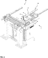
- FIGS. 2 to 9 1 shows a first exemplary embodiment of a (partially cut-out) coding device 1 for bundle packs 2, for example cigarette packs, which is integrated in a labeling system 20.
- the labeling system 20 is generally known and will not be described further here.
- the coding device 1 has a conveying device 3, an encoding unit 4 and a feed unit 12.
- the conveying direction of the bundle packs 2 by the labeling system 20 with a coding device 1 according to the invention is indicated in the figures by the gray background block arrows.
- the bundle packs 2 are transported lengthwise. It is also conceivable, however, for the bundle packs 2 to be conveyed widthwise or rotated accordingly during the conveyance.
- the coding device 1 is arranged on a frame which also carries the electronic components, such as a control unit or the power supply unit.
- the bundle packs 2 are conveyed by a conveyor belt to the coding device 1 and fed by further conveying devices for further processing after it has been coded.
- the bundle packs 2 are first fed by a conveyor belt of the feed unit 12.
- the bundle packs 2 are positioned so that they are aligned substantially parallel to a conveyor belt 5 of the conveyor 3.
- the feed unit has a punch 13, which gives the bundle packs 2 on the conveyor belt 5 and in the conveyor 3.
- the punch 13 is movable vertically to the conveyor belt 5 by being driven by an eccentric disk 14.
- the punch 13 is connected via a connecting rod 15 with the eccentric disc 14.
- the punch 13 is guided on two linear guides 16, so that the rotating movement of the eccentric disc 14 is translated into a linear-reciprocal movement of the punch 13.
- the eccentric 14 is driven by a (not shown) servo drive.
- the punch 13 displaces the bundle pack 2 laterally so that it is fed to the conveyor 3.
- the conveyor 3 has two slide rails 17 made of plastic with a low coefficient of friction, which are each arranged on one side of the conveyor belt 5.
- the slide rails 17 have a length, which is slightly larger than the length of a bundle pack 2.
- the bundle pack 2 lies completely on the slide rails 17.
- the slide rails have a height of about 2 mm, so that the abandoned from the feed unit 12 bundle pack 2 does not come into contact with the conveyor belt 5. Rather, the conveying plane of the conveyor belt 5 is at a slightly lower horizontal level.
- there are at least two sensors (not shown) which monitor the position of the bundle pack 2 in the feed unit 12 and in the conveying device 3. The achieved positioning accuracy or tolerance is ⁇ 0.1 mm.
- the conveyor belt 5 For conveying the bundle packs 2, the conveyor belt 5 has corresponding receptacles 9, which are formed in this embodiment as extending from the conveyor belt 5 noses or support and at the rear end of the respective bundle pack 2 seen in the conveying direction.
- the surface of the conveyor belt 5 is further provided with an anti-slip coating.
- the conveyor 3 on two rails 10 which extend over the entire length of the conveyor belt 5 laterally from this.
- the rails 10 are arranged so that the facing in the direction of the bundle pack 2 surfaces are slightly below the conveying plane of the conveyor belt 5. In this embodiment, the difference is 1 mm.
- the conveyor 3 has guide rails 11.
- the guide rails 11 are adjustable in their distance from the conveyor belt 5, so that the coding device 1 is adjustable to different widths packs 2.
- the conveyor belt 5 is driven in cycles, wherein the timing is synchronized with the movement of the punch 13. During a standstill of the conveyor belt 5 to be encoded bundle pack 2 is abandoned by the feed unit 12 and encoded by the encoding unit 4, as will be described in more detail below.
- the conveyor belt 5 can be driven at a maximum speed of up to 6.0 m / sec, wherein a speed of 4.5 m / sec has proven to be particularly advantageous.
- the maximum acceleration or deceleration of the conveyor belt 5 can be up to 60 m / sec 2 , wherein a value of 45 m / sec 2 has been found to be particularly suitable.
- a receptacle 9 of the conveyor belt 5 is brought into contact with the bundle pack 2 by the conveyor belt 5 starts.
- the bundle pack 2 is taken in the conveying direction and conveyed to the coding unit 4.
- the conveying device 3 has a positioning means 7 in the area of the coding unit 4.
- the positioning means 7 comprises in this embodiment a plurality of rollers 8 (here are in the Fig. 2 to 9 exemplified two rollers 8 shown), which are arranged above the conveyor belt 5.
- the rollers 8 are made of a flexible or compliant material and come into contact with the surface of the bundle pack 2, in particular in the Fig. 4 to 7 easy to recognize.
- the rollers 8 exert a force on the bundle pack 2, so that the bundle pack 2 between the conveyor belt 5 and the rollers 8 is easily clamped.
- a positioning accuracy of ⁇ 0.5 mm in the area of the coding unit 4 can be achieved.
- the coding unit 4 has two lasers 6 or laser units.
- the distance from a respective laser 6 to the bundle pack 2 to be coded is approximately 300 mm to 400 mm, preferably the distance is 190 mm to 370 mm. In this embodiment, the distance is 348 mm, which has been found to be particularly suitable.
- the laser 6 are separately adjustable at a distance to the bundle pack 2.
- the lasers 6 are laterally offset from one another by approximately 100 mm to 200 mm. As suitable, a distance of 150 mm has been found.
- the bundle packs 2 are then coded by the laser 6 during the stoppage of the conveyor belt 5 by the laser applying a laser inscription directly to the bundle pack 2 or to an outer wrapping of the bundle pack 2.
- a laser 6 has been found to be useful, which emits a laser beam having a wavelength between 1000 microns and 1100 microns, in particular with a wavelength of 1060 microns to 1070 microns.
- a wavelength of 1062 ⁇ m has proven to be particularly suitable.
- the packet of cigarettes 2a forming the bundle pack 2 are coded individually.
- the coding is applied to one of the narrow sides of the Zigarttenpierechen 2a, for example on the sides of the cigarette packet 2a, denoted by the reference numeral "2a" in Fig. 1 are provided.
- the bundle pack 2 to be encoded has a transparent outer covering (in particular made of cellophane), which is permeable to the laser beam at the corresponding points.
- the outer envelope of cigarette packets 2a provided that they have an outer envelope.
- the bundle packs 2 are conveyed to a control unit 18, which has an optical sensor or a camera unit 19.
- a control unit 18 which has an optical sensor or a camera unit 19.
- the bundle pack 2 is detected and the newly applied coding checked cigarettes pack.
- the conveying distance per cycle is about 410 mm.
- a standstill time of approximately 200 to 400 msec, in particular of 300 msec, has proved suitable.
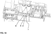
- a second embodiment of a coding device 1 according to the invention is shown. This embodiment differs from that in the Fig. 2 to 9 shown embodiment in that the positioning means 7 comprises a vacuum device 80.
- the positioning means 7 comprises a vacuum device 80.
- the vacuum device 80 is designed as a vacuum device and comprises a plurality of bores 81. These bores 81 are arranged in this embodiment in both rails 10 on both sides of the conveyor belt 5. When the conveyor belt 5 is brought to a standstill, a negative pressure is applied by the vacuum device 80 by means of bores 81, which prevents the bundle pack 2 to be coded from slipping in position relative to the conveyor belt 5 due to the inertia. In other words, the bundle pack 2 is sucked in to prevent further slippage. It is also conceivable that the positioner means 7 comprises both the Unterdurckvortechnik 80 and the rollers 8 shown in the first embodiment.
- the coding device 1 can also have more than one coding unit 4.
- These coding units 4 can also be arranged on both sides of the conveyor 3.
- positioning means 7 can also be used independently of the coding unit 4.
- the positioning means 7 is in principle quite generally intended to prevent slippage of bundle packs 2 relative to the conveyor belt 5.
Landscapes
- Engineering & Computer Science (AREA)
- Mechanical Engineering (AREA)
- Wrapping Of Specific Fragile Articles (AREA)
Description
Die vorliegende Erfindung betrifft eine Codiervorrichtung zum Codieren von Gebindepackungen, insbesondere von Zigarettengebindepackungen, ein Verfahren zum Codieren einer Gebindepackung sowie ein Etikettiersystem mit einer Codiervorrichtung. Eine Codiervorrichtung hat eine Fördereinrichtung und eine Codiereinheit, wobei die Fördereinrichtung ein taktweise angetriebenes Förderband zum Fördern der Gebindepackungen aufweist. Die Codiereinheit codiert wenigstens eine Gebindepackung während eines Stillstandes des Förderbandes.The present invention relates to a coding device for coding bundle packs, in particular cigarette packs, a method for coding a bundle pack and a labeling system with a coding device. An encoder has a conveyor and a coding unit, wherein the conveyor has a cyclically driven conveyor belt for conveying the bundle packs. The coding unit encodes at least one bundle pack during a standstill of the conveyor belt.
Derartige Gebindepackungen sind in der Tabakindustrie üblich, um die in Schachteln verpackten Zigaretten einfacher zu kommissionieren. Gemeinhin sind diese Gebindepackungen auch als Zigarettenstange bekannt und bestehen in der Regel aus einer Mehrzahl von, beispielsweise zehn, Zigarettenschachteln die in Reihen, beispielsweise zwei Reihen, zu einem Gebinde zusammengefasst werden. Um das Gebinde zu fixieren, wird dieses in der Regel mit wenigstens einer Außenumhüllung umhüllt. Die Außenumhüllung kann beispielsweise aus Papier, Pappe oder einer Kunststofffolie gebildet sein.Such packs are common in the tobacco industry to pick the packaged in cartons easier. Generally, these bundle packs are also known as cigarette rods and usually consist of a plurality of, for example ten, cigarette packs which are combined in rows, for example two rows, to form a container. In order to fix the container, this is usually wrapped with at least one outer sheath. The outer envelope may be formed, for example, from paper, cardboard or a plastic film.
Eine derartige Gebindepackung ist beispielhaft in
Die einzelnen Zigarettenpäckchen 2a haben in der Regel eine Außenumhüllung aus Cellophan. Auch die Gebindepackungen 2 werden in der Regel durch eine Außenumhüllung aus Cellophan fixiert.The individual packets of
Üblicherweise werden diese Gebindepackungen anschließend mit einer sogenannten Codierung versehen. Diese Codierung erfüllt mehrere Zwecke. Zum einen ermöglicht eine maschinenlesbare Codierung eine vereinfachte Identifikation, da so zum Beispiel Chargennummer, Hersteller, Herstelldatum und weitere Informationen schnell und einfach abrufbar sind. Zum anderen kann durch diese Codierung auch gleichzeitig ein Barcode für den Verkauf an Endkunden aufgetragen werden.Usually, these bundle packs are then provided with a so-called coding. This encoding fulfills several purposes. On the one hand, a machine-readable coding enables a simplified identification since, for example, batch number, manufacturer, date of manufacture and further information can be retrieved quickly and easily. On the other hand, this code can also be used to simultaneously apply a barcode for sale to end customers.
Eine solche Codiervorrichtung ist beispielsweise aus der
Obgleich die Codierung von Gebindepackungen mit einer aus der
Auch ist mit der aus der
Ferner ist aus der
Vor diesem Hintergrund ist es Aufgabe der vorliegenden Erfindung eine Codiervorrichtung sowie ein Verfahren zur Codierung von Gebindepackungen aufzuzeigen, bei welchem die Codierung dauerhaft ist, zigarettenpäckchenweise angebracht werden kann und die Rüst- sowie die Prozesszeit der Codiervorrichtung reduziert werden. Ferner ist es Aufgabe der vorliegenden Erfindung, die Codierqualität und -wiederholbarkeit zu verbessern.Against this background, it is an object of the present invention to provide a coding device and a method for coding packaging packages, in which the coding is permanent, cigarettes pack can be attached and the set-up and the process time of Coding be reduced. It is another object of the present invention to improve the coding quality and repeatability.
Die Lösung der Aufgabe gelingt mit einer Codiervorrichtung gemäß Anspruch 1, einem Etikettiersystem gemäß Anspruch 20 und einem Verfahren zur Codierung von Gebindepackungen gemäß Anspruch 14 Vorteilhafte Weiterbildungen sind in den abhängigen Ansprüchen beschrieben.The object is achieved with a coding device according to
Die erfindungsgemäße Codiervorrichtung zeichnet dadurch aus, dass die Codiereinheit wenigstens einen Laser bzw. wenigstens eine Lasereinheit zum Aufbringen der Codierung, insbesondere in Form einer Laserbeschriftung, aufweist. Die Eitketten werden also nicht bedruckt und aufgeklebt, sondern die Gebindepackung bzw. jeder einzelne der die Gebindepackung bildenden Zigartettenpäckchen wird direkt codiert, sodass der Einsatz von Verbrauchsmaterial weitgehend reduziert wird. Auch ergibt sich durch die Codierung mittels Laser auch eine vorteilhafte Bearbeitungszeit, da hierfür weniger als 500 msec ausreichend sind. Die Codierung ist auch dauerhaft, manipulationssicher, witterungsunabhängig und kann auch nach Herstellung der Gebindepackung zigarettenpäckchenweise angebracht werden. So kann beispielsweise Feuchtigkeit die Codierung nicht verfälschen oder unleserlich machen. Auch kann so beispielsweise die Herkunft eines jeden Zigarettenpäckchens nachvollzogen werden.The coding device according to the invention is characterized in that the coding unit has at least one laser or at least one laser unit for applying the coding, in particular in the form of a laser inscription. The egg chains are therefore not printed and glued on, but the bundle pack or each of the packs forming the pack of cigarettes is coded directly, so that the use of consumables is largely reduced. Also results from the coding by means of laser and an advantageous processing time, since less than 500 msec are sufficient for this. The coding is also durable, tamper-proof, independent of weather conditions and can also be attached to the pack of cigarettes after production of the bundle pack. For example, moisture can not falsify the encoding or make it illegible. Also, for example, the origin of each packet of cigarettes can be reconstructed.
Die Fördereinrichtung weist wenigstens ein Positioniermittel auf, welches die zu codierende Gebindepackung während des Stillstands des Förderbandes im Bereich der Codiereinheit positioniert bzw. in einer Position hält. Dies hat den Vorteil, dass alle zu codierenden Gebindepackungen im Wesentlichen an der gleichen Stelle codiert werden. Mithin kann eine hohe Codierqualität und - wiederholbarkeit erreicht werden.Hierbei ist es von Vorteil, wenn die Gebindepackungen mit einer zumindest teilweise transparenten Außenumhüllung versehen sind, wobei die transparente Außenumhüllung zumindest im Bereich der Laserbeschriftung für den vom Laser emittierten Laserstrahl durchlässig ist. Insbesondere ist es von Vorteil, wenn die Gebindepackung eine Innenumhüllung aus einem organischen Material, beispielsweise Papier oder Pappe aufweist, welche dann laserbeschriftet wird. Die Innenumhüllung ist hierbei aber nicht zwingend, da die Codierung auch auf jedes einzelne Zigartettenpäckchen direkt aufgebracht werden kann. Hierfür ist die transparente Außenumhüllung eines jeden Zigarettenpäckchens - sofern vorhanden - ebenfalls für den vom Laser emittierten Laserstrahl durchlässig. Je nach Bedarf kann die Codierung also entweder auf die Gebindepackung al solche aufgebracht werden, oder auf die einzelnen die Gebindepackung bildenden Zigartettenpäckchen. Im Folgenden werden daher unter einer Codierung einer Gebindepackung beide Möglichkeiten verstanden.The conveyor has at least one positioning means, which positions the pack to be encoded during the standstill of the conveyor belt in the region of the coding unit or in a position. This has the advantage that all bundles of packages to be coded are coded essentially in the same place. In this case, it is advantageous if the bundle packs are provided with an at least partially transparent outer wrapper, wherein the transparent outer wrapper is permeable to the laser beam emitted by the laser, at least in the region of the laser inscription. In particular, it is advantageous if the bundle pack has an inner covering of an organic material, for example paper or cardboard, which is then laser-marked. However, the inner wrapper is not mandatory, because the coding can be applied directly to every single Zigartettenpäckchen. For this purpose, the transparent outer wrapper of each packet of cigarettes - if present - is also permeable to the laser beam emitted by the laser. Depending on requirements, the coding can thus be applied either to the bundle pack as such, or to the individual bundle pack forming Zigartettenpäckchen. In the following, therefore, both ways are understood by coding a bundle pack.
Es hat sich gezeigt, dass sich für die transparente Außenumhüllung neben den bereits erwähnten Cellophanen insbesondere Materialien die zur Gruppe der Polypropylene, Polyethylene, Polyester, Polyvinylchloride, Zelluloseacetate oder den Polyactiden zählen als geeignet erwiesen haben. Als Laser kann beispielsweise ein Faser Laser der F-9000 Serie der Firma Metronic verwendet werden. Eine Beschädigung der transparenten Außenumhüllung der Gebindepackung und/ oder der Zigartettenpäckchen ist hierbei nicht zu beobachten.It has been shown that, in particular, for the transparent outer covering, in addition to the cellophanes already mentioned, materials belonging to the group of polypropylenes, polyethylenes, polyesters, Polyvinyl chlorides, cellulose acetates or the polyactides may have been found to be suitable. As a laser, for example, a fiber laser of the F-9000 series Metronic can be used. Damage to the transparent outer casing of the bundle pack and / or the Zigartettenpäckchen is not observed here.
Weiterbildend weist das Positioniermittel wenigstens eine Rolle auf, wobei die Rolle so zum Förderband angeordnet ist, dass die zu codierende Gebindepackung während des Stillstandes des Förderbandes zwischen dem Förderband und der Rolle angeordnet ist. Hierbei ist es insbesondere von Vorteil, wenn die Rolle aus einem nachgiebigen bzw. flexiblen Material besteht, beispielsweise aus einem schwammartigen Material.In a further development, the positioning means has at least one roller, wherein the roller is arranged to the conveyor belt such that the bundle pack to be coded is arranged between the conveyor belt and the roller during the stoppage of the conveyor belt. It is particularly advantageous if the roller consists of a resilient or flexible material, for example of a sponge-like material.
Es kann von Vorteil sein, wenn das Positioniermittel eine Unterdruckvorrichtung zum Ansaugen der Gebindepackung aufweist. Insbesondere ist es von Vorteil, wenn die Unterdruckvorrichtung Bohrungen umfasst, welche mit der Gebindepackung im Bereich der Codiereinheit in Kontakt kommen. Diese Unterdruckvorrichtung kann als Vakkumvorrichtung mit Vakuumbohrungen ausgebildet sein und hält die Gebindevorrichtung im Bereich der Codiereinheit.It may be advantageous if the positioning means has a vacuum device for sucking the bundle pack. In particular, it is advantageous if the vacuum device comprises bores which come into contact with the bundle pack in the region of the coding unit. This vacuum device can be designed as a vacuum device with vacuum bores and holds the container device in the region of the coding unit.
Wenn die zu codierende Gebindepackung auf dem Förderband transportiert wird und das Förderband abgebremst wird, kann es unter Umständen zu einem Verrutschen der Gebindepackung aufgrund der Massenträgheit kommen. Da die Rolle und/ oder die Unterdruckvorrichtung in dem Bereich angeordnet ist, in welchem die auf dem Förderband aufgegebene und zu codierende Gebindepackung abgebremst wird bzw. zum Stillstand kommt, hält diese die Gebindepackung in ihrer Position relativ zum Förderband. Mit anderen Worten wird so eine relative Positionsänderung zwischen Gebindepackung und Förderband verhindert. Um eine relative Positionsänderung noch wirksamer zu verhindern, kann das Förderband zusätzlich eine Oberfläche mit hohem Reibwert bzw. eine hohen Rauigkeit aufweisen. So können Toleranzen im Bereich von beispielsweise ± 0,5 mm beim Codieren eingehalten werden. Auch können so hohe Verzögerungen von bis zu 60 m/sec2 erzielt werden, sodass insgesamt die Prozesszeit reduziert werden kann.If the bundle pack to be coded is transported on the conveyor belt and the conveyor belt is braked, it may happen that the bundle slips due to the inertia. Since the roller and / or the vacuum device is arranged in the area in which the packaged on the conveyor belt to be encoded and decelerated or comes to a standstill, this holds the bundle pack in position relative to the conveyor belt. In other words, such a relative change in position between bundle pack and conveyor belt is prevented. In order to prevent a relative change in position more effective, the conveyor belt may additionally have a surface with a high coefficient of friction or a high roughness. Thus, tolerances in the range of, for example, ± 0.5 mm can be adhered to during coding. Also, such high delays of up to 60 m / sec 2 can be achieved, so that overall the process time can be reduced.
Zweckmäßigerweise weist das Förderband Aufnahmen für die Gebindepackungen auf. Diese Aufnahmen können beispielsweise als Träger, Stollen, Anschlag, Ausnehmung oder Vorsprung ausgebildet sein. Insbesondere ist es zweckmäßig, wenn sich die Aufnahmen im Wesentlichen vertikal zum bzw. vom Förderband erstrecken. Dies ermöglicht es, dass Förderband mit einer relativ hohen Maximalgeschwindigkeit von bis zu 6 m/sec zu betreiben.Appropriately, the conveyor belt has recordings for the bundle packs. These recordings may be formed, for example, as a carrier, studs, stop, recess or projection. In particular, it is expedient if the receptacles extend substantially vertically to or from the conveyor belt. This makes it possible to operate the conveyor belt at a relatively high maximum speed of up to 6 m / sec.
Weiterbildend weist die Fördereinrichtung zwei Laufschienen auf, die jeweils auf einer Seite des Förderbandes parallel zum Förderband angeordnet sind. Denkbar ist, dass die Laufschienen aus Edelstahl gebildet sind. Diese Laufschienen stabilisieren die Gebindepackungen in vorteilhafter Weise während der Förderung durch das Förderband.Further, the conveyor on two rails, which are each arranged on one side of the conveyor belt parallel to the conveyor belt. It is conceivable that the rails out Stainless steel are formed. These rails stabilize the bundle packs advantageously during conveyance through the conveyor belt.
Es ist von Vorteil, wenn die Fördereinrichtung wenigstens eine Führungsschiene aufweist, welche die zu fördernden Gebindepackungen in Förderrichtung des Förderbandes führt. Denkbar ist auch, dass eine Mehrzahl, vorzugsweise zwei Führungsschienen vorgesehen sind, die jeweils auf einer Seite des Förderbandes verlaufen. Ferner ist auch denkbar, mehrere Führungsschienen auf einer oder auf beiden Seiten des Förderbandes vorzusehen. Die wenigstens eine Führungsschiene ist zweckmäßigerweise einstellbar ausgeführt, sodass der laterale Abstand zum Förderband einstellbar ist. So kann gewährleistet werden, dass die Gebindepackungen zuverlässig und gleichförmig gefördert werden, und die Codiervorrichtung auch auf Gebindepackungen mit unterschiedlichen Abmessungen eingestellt werden kann.It is advantageous if the conveyor has at least one guide rail which guides the bundles of packages to be conveyed in the conveying direction of the conveyor belt. It is also conceivable that a plurality, preferably two guide rails are provided, each extending on one side of the conveyor belt. Furthermore, it is also conceivable to provide a plurality of guide rails on one or both sides of the conveyor belt. The at least one guide rail is expediently made adjustable, so that the lateral distance to the conveyor belt is adjustable. Thus, it can be ensured that the bundle packs are conveyed reliably and uniformly, and the coding device can also be set to bundle packs with different dimensions.
Zweckmäßigerweise weist die Codiervorrichtung eine Zuführeinheit auf, wobei eine Gebindepackung zur Förderung durch das Förderband durch einen im Wesentlichen vertikal zum Förderband verlaufenden Stempel der Zuführeinheit in die Fördereinrichtung aufgebbar ist. Dort werden die Gebindepackungen dann durch den Stempel lateral so verlagert, dass diese auf das Förderband bzw. in die Fördereinrichtung geschoben werden. Dies hat den Vorteil, dass die aufzugebenden Gebindepackungen in weitgehend gleichen Positionen auf das Förderband bzw. in die Fördereinrichtung aufgegeben werden. So können Toleranzen von bis zu ± 0,1 mm eingehalten werden.Expediently, the coding device has a feed unit, wherein a bundle pack for conveyance through the conveyor belt can be raised into the conveying device by a punch of the feed unit extending substantially vertically to the conveyor belt. There, the bundle packs are then laterally displaced by the punch so that they are pushed onto the conveyor belt or in the conveyor. This has the advantage that the packaged packs are abandoned in largely identical positions on the conveyor belt or in the conveyor. Thus, tolerances of up to ± 0.1 mm can be maintained.
Hierbei ist es insbesondere von Vorteil, wenn die Zuführeinheit die Gebindepackungen synchron mit der taktweisen Bewegung des Förderbandes aufgibt. Wenn das Förderband also im Stillstand ist, da beispielsweise eine Gebindepackung durch die Codiereinheit codiert wird, wird durch die Zuführeinheit eine weitere zu codierende Gebindepackung auf das Förderband bzw. in die Fördereinrichtung aufgegeben. Durch diesen Synchronbetrieb kann die Taktung erhöht und die gesamte Prozessdauer deutlich reduziert werden.It is particularly advantageous if the feed unit gives up the bundle packs synchronously with the cyclical movement of the conveyor belt. Thus, when the conveyor belt is at a standstill, since, for example, a bundle pack is coded by the coding unit, a further bundle pack to be coded is fed onto the conveyor belt or into the conveyor by the feed unit. Through this synchronous operation, the timing can be increased and the entire process time can be significantly reduced.
Weiterbildend weist die Fördereinrichtung im Bereich der Zuführeinheit wenigstens eine im Wesentlichen parallel zum Förderband ausgerichtete Gleitschiene auf. Die Gleitschiene hat vorzugsweise eine Länge, die wenigstes der Länge einer Gebindepackung entspricht. Es ist auch von Vorteil, wenn die Gleitschiene aus Kunststoff oder einem anderen geeigneten Material mit geringem Reibewert ist. So kann gewährleistet werden, dass die Zuführeinheit die zu codierende Gebindepackung auf das Förderband aufgibt, ohne dass die Gebindepackung verkantet oder beschädigt wird.In a further development, the conveying device has at least one slide rail oriented substantially parallel to the conveyor belt in the region of the feed unit. The slide rail preferably has a length which corresponds at least to the length of a bundle pack. It is also advantageous if the slide rail is made of plastic or another suitable material with a low coefficient of friction. Thus, it can be ensured that the feed unit gives the bundle pack to be coded onto the conveyor belt, without the bundle pack being tilted or damaged.
Hierbei ist es vorteilhaft, wenn die Höhe der wenigstens einen Gleitschiene so gewählt wird, dass eine von der Zuführeinheit aufgegebene Gebindepackung nur auf der wenigstens einen Gleitschiene aufliegt. Insbesondere ist es von Vorteil, wenn die wenigstens eine Gleitschiene eine Höhe zwischen 1 mm und 3 mm, vorzugsweise zwischen 1,5 mm und 2,5 mm und besonders bevorzugt von 2 mm aufweist. So kann gewährleistet werden, dass durch den Spalt zwischen der auf der wenigstens einen Gleitschiene aufliegenden Gebindepackung und dem Förderband eine Förderung durch das Förderband gewährleistet wird. Insbesondere kann so sichergestellt werden, dass die Aufnahmen des Förderbandes in Kontakt mit der zu fördernden Gebindepackung gebracht werden können.In this case, it is advantageous if the height of the at least one slide rail is selected so that a bundle pack abandoned by the feed unit rests only on the at least one slide rail. In particular, it is advantageous if the at least one slide rail has a height between 1 mm and 3 mm, preferably between 1.5 mm and 2.5 mm and particularly preferably of 2 mm. It can thus be ensured that a conveyance through the conveyor belt is ensured by the gap between the bundle pack resting on the at least one slide rail and the conveyor belt. In particular, it can be ensured that the recordings of the conveyor belt can be brought into contact with the bundle pack to be conveyed.
Zweckmäßigerweise weist die Codiervorrichtung wenigstens zwei Sensoren zur Erfassung der Position einer Gebindepackung in der Zuführeinheit und in der Fördereinrichtung auf. So kann festgestellt werden, ob es ein Problem bei der Aufgabe der zu codierenden Gebindepackung gegeben hat. So kann beispielsweise der Prozess angehalten werden, sodass es nicht zu einer Verstopfung oder Beschädigung kommt.Expediently, the coding device has at least two sensors for detecting the position of a bundle pack in the feed unit and in the conveying device. Thus, it can be determined whether there has been a problem in the task of the bundle pack to be coded. For example, the process may be stopped so that it does not become clogged or damaged.
Es ist von Vorteil, wenn die Codiervorrichtung eine Kontrolleinheit aufweist, die ausgelegt ist, um die Codierung der Gebindepackung zu überprüfen. Stellt die Kontrolleinheit fest, dass die Codierung fehlerhaft ist, kann die entsprechende Gebindepackung unmittelbar oder in einem nachfolgenden Prozessschritt ausgeschleust werden. Der Inhalt der Gebindepackung kann dann dem Prozess erneut zugeführt werden. Zum einen lässt sich somit der Ausschuss minimieren. Zum anderen wird die gesamte Produktqualität gesteigert.It is advantageous if the coding device has a control unit which is designed to check the coding of the bundle pack. If the control unit determines that the coding is faulty, the corresponding bundle can be removed directly or in a subsequent process step. The contents of the bundle can then be fed back to the process. On the one hand, the waste can be minimized. On the other hand, the overall product quality is increased.
Hierbei ist es von Vorteil, wenn die Kontrolleinheit wenigstens einen optischen Sensor und/ oder eine Kameraeinheit aufweist. Damit wird eine schnelle und effiziente Kontrolle der codierten Gebindepackungen gewährleistet.In this case, it is advantageous if the control unit has at least one optical sensor and / or one camera unit. This ensures fast and efficient control of the coded bundle packs.
Verfahrensseitig wird die Aufgabe durch ein Verfahren zur Codierung einer Gebindepackung mit einer erfindungsgemäßen Codiervorrichtung gelöst, welches die folgenden Schritte aufweist:
- Aufgeben einer zu codierenden Gebindepackung auf das Förderband der Fördereinrichtung;
- Fördern der zu codierenden Gebindepackung zur Codiereinheit;
- Anhalten des Förderbandes und Positionieren der zu codierenden Gebindepackung mit dem Positioniermittel im Bereich der Codiereinheit,
- Aufbringen der Codierung auf die Gebindepackung mit dem Laser, insbesondere in Form einer Laserbeschriftung.
- Placing a bundle pack to be coded on the conveyor belt of the conveyor;
- Conveying the bundle pack to be coded to the coding unit;
- Stopping the conveyor belt and positioning the bundle pack to be coded with the positioning means in the area of the coding unit,
- Applying the coding on the bundle pack with the laser, in particular in the form of a laser marking.
Zweckmäßigerweise wird die Gebindepackung von der Zuführeinheit auf das Förderband geschoben bzw. so positioniert, dass die Gebindepackung durch das Förderband transportiert werden kann. Es ist auch von Vorteil, wenn die Codierung durch die Kontrolleinheit überprüft wird.Conveniently, the bundle pack is pushed by the feed unit onto the conveyor belt or positioned so that the bundle pack can be transported through the conveyor belt. It is also advantageous if the coding is checked by the control unit.
Die Codiervorrichtung ist insbesondere so zu betreiben, dass das Förderband in einem Takt zwischen 200 msec und 400 msec, vorzugsweise zwischen 250 msec und 350 msec und besonderes bevorzugt für 300 msec angehalten wird.The coding device is in particular to be operated so that the conveyor belt is stopped in a cycle between 200 msec and 400 msec, preferably between 250 msec and 350 msec, and particularly preferably for 300 msec.
Auch ist es vorteilhaft, wenn das Förderband mit einer maximalen Geschwindigkeit zwischen 3 m/sec und 6 m/sec, vorzugsweise zwischen 4 m/sec und 5 m/sec und besonders bevorzugt mit 4,5 m/sec bewegt wird.It is also advantageous if the conveyor belt is moved at a maximum speed between 3 m / sec and 6 m / sec, preferably between 4 m / sec and 5 m / sec and particularly preferably at 4.5 m / sec.
Zweckmäßigerweise wird das Förderband zwischen 30 m/sec2 und 60 m/sec2, vorzugsweise zwischen 40 m/sec2 und 50 m/sec2 und besonders bevorzugt mit 45 m/sec2 beschleunigt und/ oder verzögert.Expediently, the conveyor belt is accelerated and / or decelerated between 30 m / sec 2 and 60 m / sec 2 , preferably between 40 m / sec 2 and 50 m / sec 2 and particularly preferably at 45 m / sec 2 .
Die vorstehenden Parameter haben sich einzeln oder in Kombination als vorteilhaft herausgestellt, um eine hohe Codierqualität bei möglichst geringer Prozesszeit zu erreichen.The above parameters have been found to be advantageous, individually or in combination, in order to achieve a high coding quality with the least possible processing time.
Ferner betrifft die Erfindung auch ein Etikettiersystem mit einer erfindungsgemäßen Codiervorrichtung.Furthermore, the invention also relates to a labeling system with a coding device according to the invention.
Nachfolgend wird die Erfindung anhand der in den Figuren gezeigten Ausführungsbeispiele näher erläutert. Hierbei zeigen schematisch
- Fig. 2
- eine erste perspektivische Ansicht einer Codiervorrichtung gemäß einem ersten Ausführungsbeispiel;
- Fig. 3
- eine zweite perspektivische Ansicht der in
Fig. 1 gezeigten Codiervorrichtung; - Fig. 4
- eine Draufsicht auf die in den
Fig. 2 undFig. 3 gezeigte Codiervorrichtung; - Fig.5
- eine erste perspektivische Detailansicht einer Codiereinheit und einer Zuführeinheit gemäß dem ersten Ausführungsbeispiel;
- Fig. 6
- eine zweite perspektivische Detailansicht einer Codiereinheit und einer Zuführeinheit gemäß dem ersten Ausführungsbeispiel;
- Fig.7
- eine dritte perspektivische Detailansicht einer Codiereinheit und einer Zuführeinheit mit freigeschnittenem Gehäuse gemäß dem ersten Ausführungsbeispiel;
- Fig. 8
- eine vierte perspektivische Detailansicht einer Codiereinheit und einer Zuführeinheit mit freigeschnittenem Gehäuse gemäß dem ersten Ausführungsbeispiel;
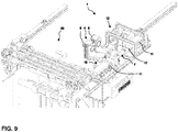
- Fig.9
- eine perspektivische Ansicht einer Codiervorrichtung mit freigeschnittenem Gehäuse gemäß dem ersten Ausführungsbeispiel; und
- Fig. 10
- eine perspektivische Detailansicht einer Codiereinheit und einer Zuführeinheit gemäß einem zweiten Ausführungsbeispiel.
- Fig. 2
- a first perspective view of a coding device according to a first embodiment;
- Fig. 3
- a second perspective view of the in
Fig. 1 shown coding device; - Fig. 4
- a plan view of the in the
Fig. 2 andFig. 3 shown coding device; - Figure 5
- a first perspective detail view of a coding unit and a feed unit according to the first embodiment;
- Fig. 6
- a second perspective detail view of a coding unit and a feed unit according to the first embodiment;
- Figure 7
- a third perspective detail view of a coding unit and a feed unit with cut-free housing according to the first embodiment;
- Fig. 8
- a fourth detailed perspective view of a coding unit and a feed unit with cut housing according to the first embodiment;
- Figure 9
- a perspective view of a coding device with cut housing according to the first embodiment; and
- Fig. 10
- a detailed perspective view of a coding unit and a feed unit according to a second embodiment.
In den
Wie in
Die Gebindepackungen 2 werden zunächst durch ein Förderband der Zuführeinheit 12 zugeführt. Hier sind die Gebindepackungen 2 so positioniert, dass diese im Wesentlichen parallel zu einem Förderband 5 der Fördereinrichtung 3 ausgerichtet sind. Die Zuführeinheit weist einen Stempel 13 auf, der die Gebindepackungen 2 auf das Förderband 5 bzw. in die Fördereinrichtung 3 aufgibt. Der Stempel 13 ist vertikal zum Förderband 5 beweglich, indem dieser über eine Exzenterscheibe 14 angetrieben wird. In diesem Ausführungsbeispiel ist der Stempel 13 über ein Pleuel 15 mit der Exzenterscheibe 14 verbunden. Der Stempel 13 wird an zwei Linearführungen 16 geführt, sodass die drehende Bewegung der Exzenterscheibe 14 in eine linear-reziproke Bewegung des Stempels 13 übersetzt wird. Die Exzenterscheibe 14 wird über einen (nicht dargestellten) Servoantrieb angetrieben.The bundle packs 2 are first fed by a conveyor belt of the
Der Stempel 13 verlagert die Gebindepackung 2 lateral, sodass diese der Fördereinrichtung 3 zugeführt wird. Um eine sichere Aufgabe der zu codierenden Gebindepackung 2 zu gewährleisten, weist die Fördereinrichtung 3 zwei Gleitschienen 17 aus Kunststoff mit geringem Reibwert auf, welche jeweils auf einer Seite des Förderbandes 5 angeordnet sind. Die Gleitschienen 17 haben eine Länge, die etwas größer ist als die Länge einer Gebindepackung 2. Dadurch liegt die Gebindepackung 2 vollständig auf den Gleitschienen 17 auf. Ferner haben die Gleitschienen eine Höhe von ca. 2 mm, sodass die von der Zuführeinheit 12 aufgegebene Gebindepackung 2 nicht mit dem Förderband 5 in Kontakt kommt. Vielmehr liegt die Förderebene des Förderbandes 5 auf einem leicht niedrigeren horizontalen Niveau. Um den Aufgabevorgang der zu codierenden Gebindepackung 2 zu überwachen sind wenigstens zwei (nicht dargestellte) Sensoren vorhanden, die die Position der Gebindepackung 2 in der Zuführeinheit 12 und in der Fördereinrichtung 3 überwachen. Die erzielte Positioniergenauigkeit bzw. Toleranz liegt hier bei ± 0,1 mm.The
Zur Beförderung der Gebindepackungen 2 weist das Förderband 5 entsprechende Aufnahmen 9 auf, die in diesem Ausführungsbeispiel als sich vom Förderband 5 erstreckende Nasen bzw. Träger ausgebildet sind und an dem in Förderrichtung gesehen hinteren Ende der jeweiligen Gebindepackung 2 anschlagen. Die Oberfläche des Förderbandes 5 ist ferner mit einer Anti-Rutsch-Beschichtung versehen. Des Weiteren weist die Fördereinrichtung 3 zwei Laufschienen 10 auf, die sich über die gesamte Länge des Förderbandes 5 jeweils seitlich von diesem erstrecken. Die Laufschienen 10 sind so angeordnet, dass die in Richtung der Gebindepackung 2 zeigenden Oberflächen leicht unterhalb der Förderebene des Förderbandes 5 liegen. In diesem Ausführungsbeispiel beträgt die Differenz 1 mm. So können die Gebindepackungen 2 während der Förderung stabilisiert werden. Um eine seitliche Führung der Gebindepackungen 2 zu gewährleisten, weist die Fördereinrichtung 3 Führungsschienen 11 auf. Die Führungsschienen 11 sind in ihrem Abstand zum Förderband 5 verstellbar, sodass die Codiervorrichtung 1 auf unterschiedlich breite Gebindepackungen 2 einstellbar ist.For conveying the bundle packs 2, the
Das Förderband 5 wird taktweise angetrieben, wobei die Taktung mit der Bewegung des Stempels 13 synchronisiert ist. Während eines Stillstands der Förderbands 5 wird eine zu codierende Gebindepackung 2 durch die Zuführeinheit 12 aufgegeben und durch die Codiereinheit 4 codiert, wie nachfolgend noch näher beschrieben wird. Das Förderband 5 kann mit einer Maximalgeschwindigkeit von bis zu 6,0 m/sec angetrieben werden, wobei sich eine Geschwindigkeit von 4,5 m/sec als besonders vorteilhaft herausgestellt hat. Die maximale Beschleunigung bzw. Verzögerung des Förderbandes 5 kann bis zu 60 m/sec2 betragen, wobei sich ein Wert von 45 m/sec2 als besonders geeignet ergeben hat.The
Um die auf den Gleitschienen 17 aufliegende Gebindepackung 2 mit dem Förderband 5 in Förderrichtung zu fördern, wird eine Aufnahme 9 des Förderbandes 5 in Kontakt mit der Gebindepackung 2 gebracht, indem das Förderband 5 anläuft. Somit wird die Gebindepackung 2 in Förderrichtung mitgenommen und zur Codiereinheit 4 gefördert.To promote the resting on the
Um die zu codierende Gebindepackung 2 für die Codierung durch die Codiereinheit 4 korrekt zu positionieren weist die Fördereinrichtung 3 ein Positioniermittel 7 im Bereich der Codiereinheit 4 auf. Das Positioniermittel 7 umfasst in diesem Ausführungsbeispiel eine Mehrzahl an Rollen 8 (hier sind in den
Zum Codieren der Gebindepackungen 2 weist die Codiereinheit 4 zwei Laser 6 bzw. Lasereinheiten auf. Der Abstand von einem jeweiligen Laser 6 zu der zu codierenden Gebindepackung 2 beträgt ungefähr 300 mm bis 400 mm, bevorzugt beträgt der Abstand 190 mm bis 370 mm. In diesem Ausführungsbeispiel beträgt der Abstand 348 mm, welcher sich als besonders geeignet herausgestellt hat. Die Laser 6 sind im Abstand zur Gebindepackung 2 separat einstellbar. Die Laser 6 sind seitlich zueinander um ca. 100 mm bis 200 mm versetzt angeordnet. Als geeignet hat sich ein Abstand von 150 mm herausgestellt.For coding the bundle packs 2, the
Die Gebindepackungen 2 werden dann durch die Laser 6 während des Stillstands des Förderbands 5 codiert, indem der Laser direkt auf die Gebindepackung 2 bzw. auf eine Außenumhüllung der Gebindepackung 2 eine Laserbeschriftung aufträgt. Insbesondere hat sich hierbei ein Laser 6 als brauchbar herausgestellt, der einen Laserstrahl mit einer Wellenlänge zwischen 1000 µm und 1100 µm, insbesondere mit einer Wellenlänge von 1060 µm bis 1070 µm emittiert. Als besonders geeignet hat sich eine Wellenlänge von 1062 µm ergeben.The bundle packs 2 are then coded by the
Durch die dargestellte Codiereinheit 4 können auch die die Gebindepackung 2 bildenden Zigarettenpäckchen 2a (vgl.
Nach dem Codiervorgang werden die Gebindepackungen 2 zu einer Kontrolleinheit 18 gefördert, die einen optischen Sensor bzw. eine Kameraeinheit 19 aufweist. Durch mehrere (in diesem Fall fünf) Trigger- Sensoren 21 wird die Gebindepackung 2 erfasst und die eben aufgetragene Codierung zigarettenpäckchenweise überprüft. Hierbei wird vorzugsweise immer die Codierung von jeweils zwei übereinander angeordneten Zigarettenpäckchen 2a überprüft. Wenn die Codierung fehlerhaft ist, wird die Gebindepackung 2 ausgeschleust. Dies kann beispielsweise unmittelbar im Anschluss an die Kontrolleinheit 18 durch geeignete Mittel realisiert werden. Alternativ kann die fehlerhaft codierte Gebindepackung auch in einem anderen Bereich des Etikettiersystems 20 oder in einem nachfolgenden Prozessabschnitt ausgeschleust werden.After the coding process, the bundle packs 2 are conveyed to a
Bei diesem Ausführungsbeispiel beträgt die Förderstrecke pro Takt ca. 410 mm. Für die Codierung hat sich eine Stillstandzeit von ungefähr 200 bis 400 msec, insbesondere von 300 msec, als geeignet erwiesen.In this embodiment, the conveying distance per cycle is about 410 mm. For the coding, a standstill time of approximately 200 to 400 msec, in particular of 300 msec, has proved suitable.
In
Die Unterdruckvorrichtung 80 ist als Vakuumvorrichtung ausgebildet und umfasst mehrere Bohrungen 81. Diese Bohrungen 81 sind in diesem Ausführungsbeispiel in beiden Laufschienen 10 auf beiden Seiten des Förderbandes 5 angeordnet. Wenn das Förderband 5 zum Stillstand gebracht wird, wird durch die Unterdruckvorrichtung 80 mittels de Bohrungen 81 ein Unterdruck angelegt, der verhindert, dass die zu codierende Gebindepackung 2 aufgrund der Massenträgheit in ihrer Position relativ zum Förderband 5 verrutscht. Mit anderen Worten wird die Gebindepackung 2 angesaugt, um ein Weiterrutschen zu verhindern. Denkbar ist auch, dass das Positionermittel 7 sowohl die Unterdurckvorrichtung 80 als auch die im ersten Ausführungsbeispiel gezeigten Rollen 8 umfasst.The
Selbstverständlich kann die erfindungsgemäße Codiervorrichtung 1 auch mehr als eine Codiereinheit 4 aufweisen. Diese Codiereinheiten 4 können auch beidseitig der Fördereinrichtung 3 angeordnet sein.Of course, the
Ferner kann das erfindungsgemäße Positioniermittel 7 auch unabhängig von der Codiereinheit 4 verwendet werden. Das Positioniermittel 7 eignet sich im Prinzip ganz allgemein dazu, ein Verrutschen von Gebindepackungen 2 relativ zum Förderband 5 zu verhindern.Furthermore, the positioning means 7 according to the invention can also be used independently of the
- 11
- Codiervorrichtungcoding
- 22
- Gebindepackungmultipack
- 2a2a
- Zigarettenpäckchenpacket of cigarettes
- 33
- FördereinrichtungConveyor
- 44
- Codiereinheitcoding
- 55
- Förderbandconveyor belt
- 66
- Laserlaser
- 77
- Positioniermittelpositioning
- 88th
- Rollerole
- 99
- Aufnahmeadmission
- 1010
- Laufschienerunner
- 1111
- Führungsschieneguide rail
- 1212
- Zuführeinheitfeed
- 1313
- Stempelstamp
- 1414
- Exzenterscheibeeccentric
- 1515
- Pleuelpleuel
- 1616
- Linearführunglinear guide
- 1717
- Gleitschieneslide
- 1818
- Kontrolleinheitcontrol unit
- 1919
- optischer Sensor/ Kameraeinheitoptical sensor / camera unit
- 2020
- Etikettiersystemlabeling system
- 2121
- Triggersensortrigger sensor
- 8080
- UnterdruckvorrichtungVacuum device
- 8181
- Bohrungdrilling
Claims (20)
- A coding device (1) for coding of packing units (2), in particular packing units of cigarettes, which has a conveying means (3) and a coding unit (4),
wherein the conveying means (3) comprises a conveyor belt (5) for transporting the packing units (2), and
wherein the coding unit (4) comprises at least one laser (6) for applying a coding in the form of a laser inscription, characterized in that
the conveyor belt (5) is driven in a cyclical manner, and the coding unit (4) performs coding of at least one packing unit (2) while the conveyor belt (5) is being stopped, wherein the conveying means (3) comprises at least one positioning means (7) which positions the packing unit (2) to be coded in the zone of the coding unit (4) during the stop of the conveyor belt (5). - The coding device (1) according to claim 1, characterized in that
the positioning means (7) comprises at least one roller (8) made in particular of a flexible material, wherein the roller (8), in relation to the conveyor belt (5), is arranged so that, during a stop of the conveyor belt (5), the packing unit (2) to be coded is disposed between the conveyor belt (5) and the roller (8). - The coding device (1) according to any of the preceding claims, characterized in that the positioning means (7) comprises a vacuum device (80) for holding by suction the packing unit (2) to be coded.
- The coding device (1) according to any of the preceding claims, characterized in that the conveyor belt (5) comprises reception means (9) for the packing units (2).
- The coding device (1) according to any of the preceding claims, characterized in that the conveying means (3) comprises two rails (10), wherein the rails (10) are arranged on either side of the conveyor belt (5), in parallel to the conveyor belt (5).
- The coding device (1) according to any of the preceding claims, characterized in that the conveying means (3) comprises at least one guiding rail (11), wherein the guiding rail (11) is guiding the packing units (2) to be transported in the conveying direction of the conveyor belt (5).
- The coding device (1) according to any of the preceding claims, characterized in that the coding device (1) comprises a feeder unit (12), wherein a packing unit, in order to be transported by the conveyor belt (5), can be placed onto the conveying means (3) by a piston (13) of the feeder unit (12), which piston is vertically movable in relation to the conveyor belt (5).
- The coding device (1) according to claim 7, characterized in that
the feeder unit (12) carries out placing of the packing units (2) synchronized with the time cycles of the movement of the conveyor belt (5). - The coding device (1) according to any of the preceding claims 7 or 8, characterized in that the conveying means (3), in the zone of the feeder unit (12), comprises at least one slide rail, which is oriented in parallel to the conveyor belt (5), wherein the length of the slide rail (17) preferably at least equals the length of a packing unit (2).
- The coding device (1) according to claim 9, characterized in that
the height of the at least one slide rail (17) is chosen so that a packing unit (2) after having been placed by the feeder unit (12) rests only on the at least one slide rail (17). - The coding device (1) according to any of the preceding claims 7 to 10, characterized in that
the coding device (1) comprises at least two sensors for detecting a position of a packing unit (2) in the feeder unit (12) and in the conveying unit (3). - The coding device (1) according to any of the preceding claims, characterized in that the coding device (1) comprises a monitoring unit (18), wherein the monitoring unit (18) is configured to inspect the coding of the packing units (2).
- The coding device (1) according to claim 12, characterized in that the monitoring unit (18) comprises at least one optical sensor (19) and/or a camera unit (19).
- A method for coding a packing unit (2) by means of a coding device (1) according to any of the preceding claims, comprising the steps of:placing a packing unit (2) to be coded onto the conveyor belt (5) of the conveying means (3), transporting the packing unit (2) to be coded to the coding unit (4),stopping the conveyor belt (5) and positioning the packing unit (2) to be coded by means of the positioning means (7) in the zone of the coding unit (4),applying the coding on the packing unit (2) in the form of a laser inscription.
- The method according to claim 14, wherein a packing unit (2) to be coded is pushed onto the conveyor belt (5) by the feeder unit (12).
- The method according to claim 14 or 15, wherein a coding after having been applied is inspected by the monitoring unit (18).
- The method according to any of the preceding claims 14 to 16, wherein the conveyor belt (5), in one time cycle, is being stopped between 200 msec and 400 msec, preferably between 250 msec and 350 msec, and particularly preferred for 300 msec.
- The method according to any of the preceding claims 14 to 17, wherein the conveyor belt (5) is being driven with a maximum velocity between 3 m/sec and 6 m/sec, preferably between 4 m/sec and 5 m/sec, and particularly preferred with 4.5 m/sec.
- The method according to any of the preceding claims 14 to 18, wherein the conveyor belt (5) is being accelerated and/or decelerated between 30 m/sec2 and 60 m/sec2, preferably between 40 m/sec2 and 50 m/sec2, and particularly preferred with 45 m/sec2.
- A labeling system (20) having a coding device (1) according to any of the claims 1 to 13.
Priority Applications (3)
| Application Number | Priority Date | Filing Date | Title |
|---|---|---|---|
| EP15159480.1A EP3070013B1 (en) | 2015-03-17 | 2015-03-17 | Coding device for coding container packaging, method for coding a container packaging and labelling system with a coding device |
| PL15159480T PL3070013T3 (en) | 2015-03-17 | 2015-03-17 | Coding device for coding container packaging, method for coding a container packaging and labelling system with a coding device |
| RS20170787A RS56160B1 (en) | 2015-03-17 | 2015-03-17 | Coding device for coding container packaging, method for coding a container packaging and labelling system with a coding device |
Applications Claiming Priority (1)
| Application Number | Priority Date | Filing Date | Title |
|---|---|---|---|
| EP15159480.1A EP3070013B1 (en) | 2015-03-17 | 2015-03-17 | Coding device for coding container packaging, method for coding a container packaging and labelling system with a coding device |
Publications (2)
| Publication Number | Publication Date |
|---|---|
| EP3070013A1 EP3070013A1 (en) | 2016-09-21 |
| EP3070013B1 true EP3070013B1 (en) | 2017-05-10 |
Family
ID=52686205
Family Applications (1)
| Application Number | Title | Priority Date | Filing Date |
|---|---|---|---|
| EP15159480.1A Active EP3070013B1 (en) | 2015-03-17 | 2015-03-17 | Coding device for coding container packaging, method for coding a container packaging and labelling system with a coding device |
Country Status (3)
| Country | Link |
|---|---|
| EP (1) | EP3070013B1 (en) |
| PL (1) | PL3070013T3 (en) |
| RS (1) | RS56160B1 (en) |
Families Citing this family (2)
| Publication number | Priority date | Publication date | Assignee | Title |
|---|---|---|---|---|
| EP3577030A1 (en) * | 2017-02-01 | 2019-12-11 | Hicof AG | Method and coding line for serializing a plurality of products |
| IT201800006359A1 (en) * | 2018-06-18 | 2019-12-18 | Packet laser printing unit |
Family Cites Families (5)
| Publication number | Priority date | Publication date | Assignee | Title |
|---|---|---|---|---|
| DE10004022A1 (en) * | 2000-01-31 | 2001-08-02 | Focke & Co | Method and device for applying codes to (cigarette) packs |
| US20010032138A1 (en) * | 2000-03-15 | 2001-10-18 | Janiak Martin J. | Real time tax indicia system |
| DE10221837B4 (en) * | 2002-05-16 | 2005-10-20 | Bat Cigarettenfab Gmbh | Apparatus and method for identifying cigarette packets |
| US20090314413A1 (en) * | 2007-12-07 | 2009-12-24 | R.E.D. Stamp, Inc. | Apparatus and method for applying tax stamps |
| DE102009004134A1 (en) | 2008-11-28 | 2010-06-02 | Focke & Co.(Gmbh & Co. Kg) | Method and device for producing bundle packs and bundle packs |
-
2015
- 2015-03-17 RS RS20170787A patent/RS56160B1/en unknown
- 2015-03-17 PL PL15159480T patent/PL3070013T3/en unknown
- 2015-03-17 EP EP15159480.1A patent/EP3070013B1/en active Active
Also Published As
| Publication number | Publication date |
|---|---|
| RS56160B1 (en) | 2017-11-30 |
| EP3070013A1 (en) | 2016-09-21 |
| PL3070013T3 (en) | 2017-12-29 |
Similar Documents
| Publication | Publication Date | Title |
|---|---|---|
| EP2352676B1 (en) | Method and device for producing bundle packages and bundle package | |
| DE19824797B4 (en) | Bag manufacturing apparatus and method for manufacturing foil bags | |
| DE1511886A1 (en) | Labeling machine, operating procedures and label strips intended for use in such a machine | |
| EP2567904B1 (en) | Device for selective removal of labels arranged on a backing strip | |
| DE102008011493A1 (en) | Method for disposal of spent embossing foil web and embossing device with continuously operating disposal device | |
| DD296641A5 (en) | ONLINE LAYERING DEVICE FOR LETTERING MACHINES | |
| DE69919936T2 (en) | A unit and method for manufacturing a group of articles in a packaging machine | |
| EP3081927A1 (en) | Device for packaging loose medicament portions and method for the operation thereof | |
| WO2022096456A1 (en) | Multipack for cigarette industry products, and method for producing same | |
| EP2763921B1 (en) | Apparatus and method for providing film sheets, application apparatus for populating articles with film sheets | |
| EP3070013B1 (en) | Coding device for coding container packaging, method for coding a container packaging and labelling system with a coding device | |
| EP1459988B1 (en) | Method and apparatus for providing codes on cigarette pack units | |
| DE19827412A1 (en) | Method and device for producing packages | |
| DE19941485A1 (en) | Packaging machine for producing packaging containing products includes exchangeable components dependent on format fitted on the packaging machine. | |
| DE3152881C2 (en) | Method and device for coding objects | |
| DE102007016426A1 (en) | Article e.g. bottle, labeling method, involves producing chads or punching wastes, and cutting and discharging chads or punching wastes in roller gap through and in form of individual separate cuts from roller gap, respectively | |
| EP0689997B1 (en) | Method for labelling and/or stamping articles transported by a conveyor | |
| WO2017178086A1 (en) | Device for packaging piece good combinations with an additional fitting device | |
| DE69510325T2 (en) | DEVICE FOR SEPARATING A SUBSTACK BY MEANS OF A SEPARATING ELEMENT AND DEVICE FOR GRAPPING A PROVIDING MARK | |
| EP0874756A1 (en) | Device and process for labelling goods | |
| EP1409351B1 (en) | Method for the application of self-adhesive labels | |
| DE102010005766B3 (en) | Device for automatically removing and storing of foil stamping stacks by punching machine, has separating gripper that is arranged above support rods for removing stamping stacks | |
| DE102015003052B4 (en) | Method and device for generating reference marks | |
| EP0076815B1 (en) | Device for unwinding of a transparent sheet from a roll | |
| DE102020133621A1 (en) | Procedure for labeling packaging |
Legal Events
| Date | Code | Title | Description |
|---|---|---|---|
| PUAI | Public reference made under article 153(3) epc to a published international application that has entered the european phase |
Free format text: ORIGINAL CODE: 0009012 |
|
| 17P | Request for examination filed |
Effective date: 20160310 |
|
| AK | Designated contracting states |
Kind code of ref document: A1 Designated state(s): AL AT BE BG CH CY CZ DE DK EE ES FI FR GB GR HR HU IE IS IT LI LT LU LV MC MK MT NL NO PL PT RO RS SE SI SK SM TR |
|
| AX | Request for extension of the european patent |
Extension state: BA ME |
|
| GRAP | Despatch of communication of intention to grant a patent |
Free format text: ORIGINAL CODE: EPIDOSNIGR1 |
|
| INTG | Intention to grant announced |
Effective date: 20161012 |
|
| GRAS | Grant fee paid |
Free format text: ORIGINAL CODE: EPIDOSNIGR3 |
|
| STAA | Information on the status of an ep patent application or granted ep patent |
Free format text: STATUS: GRANT OF PATENT IS INTENDED |
|
| GRAA | (expected) grant |
Free format text: ORIGINAL CODE: 0009210 |
|
| STAA | Information on the status of an ep patent application or granted ep patent |
Free format text: STATUS: THE PATENT HAS BEEN GRANTED |
|
| AK | Designated contracting states |
Kind code of ref document: B1 Designated state(s): AL AT BE BG CH CY CZ DE DK EE ES FI FR GB GR HR HU IE IS IT LI LT LU LV MC MK MT NL NO PL PT RO RS SE SI SK SM TR |
|
| REG | Reference to a national code |
Ref country code: GB Ref legal event code: FG4D Free format text: NOT ENGLISH |
|
| REG | Reference to a national code |
Ref country code: AT Ref legal event code: REF Ref document number: 892053 Country of ref document: AT Kind code of ref document: T Effective date: 20170515 Ref country code: CH Ref legal event code: EP |
|
| REG | Reference to a national code |
Ref country code: IE Ref legal event code: FG4D Free format text: LANGUAGE OF EP DOCUMENT: GERMAN |
|
| REG | Reference to a national code |
Ref country code: DE Ref legal event code: R096 Ref document number: 502015001005 Country of ref document: DE |
|
| REG | Reference to a national code |
Ref country code: RO Ref legal event code: EPE |
|
| REG | Reference to a national code |
Ref country code: CH Ref legal event code: NV Representative=s name: TROESCH SCHEIDEGGER WERNER AG, CH |
|
| REG | Reference to a national code |
Ref country code: NL Ref legal event code: MP Effective date: 20170510 |
|
| REG | Reference to a national code |
Ref country code: LT Ref legal event code: MG4D |
|
| PG25 | Lapsed in a contracting state [announced via postgrant information from national office to epo] |
Ref country code: LT Free format text: LAPSE BECAUSE OF FAILURE TO SUBMIT A TRANSLATION OF THE DESCRIPTION OR TO PAY THE FEE WITHIN THE PRESCRIBED TIME-LIMIT Effective date: 20170510 Ref country code: NO Free format text: LAPSE BECAUSE OF FAILURE TO SUBMIT A TRANSLATION OF THE DESCRIPTION OR TO PAY THE FEE WITHIN THE PRESCRIBED TIME-LIMIT Effective date: 20170810 Ref country code: FI Free format text: LAPSE BECAUSE OF FAILURE TO SUBMIT A TRANSLATION OF THE DESCRIPTION OR TO PAY THE FEE WITHIN THE PRESCRIBED TIME-LIMIT Effective date: 20170510 Ref country code: HR Free format text: LAPSE BECAUSE OF FAILURE TO SUBMIT A TRANSLATION OF THE DESCRIPTION OR TO PAY THE FEE WITHIN THE PRESCRIBED TIME-LIMIT Effective date: 20170510 Ref country code: ES Free format text: LAPSE BECAUSE OF FAILURE TO SUBMIT A TRANSLATION OF THE DESCRIPTION OR TO PAY THE FEE WITHIN THE PRESCRIBED TIME-LIMIT Effective date: 20170510 Ref country code: GR Free format text: LAPSE BECAUSE OF FAILURE TO SUBMIT A TRANSLATION OF THE DESCRIPTION OR TO PAY THE FEE WITHIN THE PRESCRIBED TIME-LIMIT Effective date: 20170811 |
|
| PG25 | Lapsed in a contracting state [announced via postgrant information from national office to epo] |
Ref country code: NL Free format text: LAPSE BECAUSE OF FAILURE TO SUBMIT A TRANSLATION OF THE DESCRIPTION OR TO PAY THE FEE WITHIN THE PRESCRIBED TIME-LIMIT Effective date: 20170510 Ref country code: IS Free format text: LAPSE BECAUSE OF FAILURE TO SUBMIT A TRANSLATION OF THE DESCRIPTION OR TO PAY THE FEE WITHIN THE PRESCRIBED TIME-LIMIT Effective date: 20170910 Ref country code: SE Free format text: LAPSE BECAUSE OF FAILURE TO SUBMIT A TRANSLATION OF THE DESCRIPTION OR TO PAY THE FEE WITHIN THE PRESCRIBED TIME-LIMIT Effective date: 20170510 Ref country code: BG Free format text: LAPSE BECAUSE OF FAILURE TO SUBMIT A TRANSLATION OF THE DESCRIPTION OR TO PAY THE FEE WITHIN THE PRESCRIBED TIME-LIMIT Effective date: 20170810 Ref country code: LV Free format text: LAPSE BECAUSE OF FAILURE TO SUBMIT A TRANSLATION OF THE DESCRIPTION OR TO PAY THE FEE WITHIN THE PRESCRIBED TIME-LIMIT Effective date: 20170510 |
|
| PG25 | Lapsed in a contracting state [announced via postgrant information from national office to epo] |
Ref country code: SK Free format text: LAPSE BECAUSE OF FAILURE TO SUBMIT A TRANSLATION OF THE DESCRIPTION OR TO PAY THE FEE WITHIN THE PRESCRIBED TIME-LIMIT Effective date: 20170510 Ref country code: CZ Free format text: LAPSE BECAUSE OF FAILURE TO SUBMIT A TRANSLATION OF THE DESCRIPTION OR TO PAY THE FEE WITHIN THE PRESCRIBED TIME-LIMIT Effective date: 20170510 Ref country code: DK Free format text: LAPSE BECAUSE OF FAILURE TO SUBMIT A TRANSLATION OF THE DESCRIPTION OR TO PAY THE FEE WITHIN THE PRESCRIBED TIME-LIMIT Effective date: 20170510 Ref country code: EE Free format text: LAPSE BECAUSE OF FAILURE TO SUBMIT A TRANSLATION OF THE DESCRIPTION OR TO PAY THE FEE WITHIN THE PRESCRIBED TIME-LIMIT Effective date: 20170510 |
|
| REG | Reference to a national code |
Ref country code: DE Ref legal event code: R026 Ref document number: 502015001005 Country of ref document: DE |
|
| PLBI | Opposition filed |
Free format text: ORIGINAL CODE: 0009260 |
|
| PLAX | Notice of opposition and request to file observation + time limit sent |
Free format text: ORIGINAL CODE: EPIDOSNOBS2 |
|
| PG25 | Lapsed in a contracting state [announced via postgrant information from national office to epo] |
Ref country code: IT Free format text: LAPSE BECAUSE OF FAILURE TO SUBMIT A TRANSLATION OF THE DESCRIPTION OR TO PAY THE FEE WITHIN THE PRESCRIBED TIME-LIMIT Effective date: 20170510 Ref country code: SM Free format text: LAPSE BECAUSE OF FAILURE TO SUBMIT A TRANSLATION OF THE DESCRIPTION OR TO PAY THE FEE WITHIN THE PRESCRIBED TIME-LIMIT Effective date: 20170510 |
|
| 26 | Opposition filed |
Opponent name: FOCKE & CO. (GMBH & CO. KG) Effective date: 20180208 |
|
| PLBB | Reply of patent proprietor to notice(s) of opposition received |
Free format text: ORIGINAL CODE: EPIDOSNOBS3 |
|
| PG25 | Lapsed in a contracting state [announced via postgrant information from national office to epo] |
Ref country code: MT Free format text: LAPSE BECAUSE OF FAILURE TO SUBMIT A TRANSLATION OF THE DESCRIPTION OR TO PAY THE FEE WITHIN THE PRESCRIBED TIME-LIMIT Effective date: 20170510 |
|
| REG | Reference to a national code |
Ref country code: CH Ref legal event code: PL |
|
| PG25 | Lapsed in a contracting state [announced via postgrant information from national office to epo] |
Ref country code: MC Free format text: LAPSE BECAUSE OF FAILURE TO SUBMIT A TRANSLATION OF THE DESCRIPTION OR TO PAY THE FEE WITHIN THE PRESCRIBED TIME-LIMIT Effective date: 20170510 |
|
| REG | Reference to a national code |
Ref country code: BE Ref legal event code: MM Effective date: 20180331 |
|
| REG | Reference to a national code |
Ref country code: IE Ref legal event code: MM4A |
|
| PG25 | Lapsed in a contracting state [announced via postgrant information from national office to epo] |
Ref country code: IE Free format text: LAPSE BECAUSE OF NON-PAYMENT OF DUE FEES Effective date: 20180317 |
|
| PG25 | Lapsed in a contracting state [announced via postgrant information from national office to epo] |
Ref country code: LI Free format text: LAPSE BECAUSE OF NON-PAYMENT OF DUE FEES Effective date: 20180331 Ref country code: CH Free format text: LAPSE BECAUSE OF NON-PAYMENT OF DUE FEES Effective date: 20180331 Ref country code: BE Free format text: LAPSE BECAUSE OF NON-PAYMENT OF DUE FEES Effective date: 20180331 |
|
| PG25 | Lapsed in a contracting state [announced via postgrant information from national office to epo] |
Ref country code: FR Free format text: LAPSE BECAUSE OF NON-PAYMENT OF DUE FEES Effective date: 20180331 |
|
| GBPC | Gb: european patent ceased through non-payment of renewal fee |
Effective date: 20190317 |
|
| PG25 | Lapsed in a contracting state [announced via postgrant information from national office to epo] |
Ref country code: GB Free format text: LAPSE BECAUSE OF NON-PAYMENT OF DUE FEES Effective date: 20190317 |
|
| PLCK | Communication despatched that opposition was rejected |
Free format text: ORIGINAL CODE: EPIDOSNREJ1 |
|
| APBM | Appeal reference recorded |
Free format text: ORIGINAL CODE: EPIDOSNREFNO |
|
| APBP | Date of receipt of notice of appeal recorded |
Free format text: ORIGINAL CODE: EPIDOSNNOA2O |
|
| APAH | Appeal reference modified |
Free format text: ORIGINAL CODE: EPIDOSCREFNO |
|
| PG25 | Lapsed in a contracting state [announced via postgrant information from national office to epo] |
Ref country code: PT Free format text: LAPSE BECAUSE OF FAILURE TO SUBMIT A TRANSLATION OF THE DESCRIPTION OR TO PAY THE FEE WITHIN THE PRESCRIBED TIME-LIMIT Effective date: 20170510 |
|
| PG25 | Lapsed in a contracting state [announced via postgrant information from national office to epo] |
Ref country code: MK Free format text: LAPSE BECAUSE OF NON-PAYMENT OF DUE FEES Effective date: 20170510 Ref country code: HU Free format text: LAPSE BECAUSE OF FAILURE TO SUBMIT A TRANSLATION OF THE DESCRIPTION OR TO PAY THE FEE WITHIN THE PRESCRIBED TIME-LIMIT; INVALID AB INITIO Effective date: 20150317 Ref country code: CY Free format text: LAPSE BECAUSE OF FAILURE TO SUBMIT A TRANSLATION OF THE DESCRIPTION OR TO PAY THE FEE WITHIN THE PRESCRIBED TIME-LIMIT Effective date: 20170510 |
|
| APBQ | Date of receipt of statement of grounds of appeal recorded |
Free format text: ORIGINAL CODE: EPIDOSNNOA3O |
|
| PG25 | Lapsed in a contracting state [announced via postgrant information from national office to epo] |
Ref country code: AL Free format text: LAPSE BECAUSE OF FAILURE TO SUBMIT A TRANSLATION OF THE DESCRIPTION OR TO PAY THE FEE WITHIN THE PRESCRIBED TIME-LIMIT Effective date: 20170510 |
|
| PG25 | Lapsed in a contracting state [announced via postgrant information from national office to epo] |
Ref country code: SI Free format text: LAPSE BECAUSE OF NON-PAYMENT OF DUE FEES Effective date: 20180317 |
|
| REG | Reference to a national code |
Ref country code: DE Ref legal event code: R100 Ref document number: 502015001005 Country of ref document: DE |
|
| APBU | Appeal procedure closed |
Free format text: ORIGINAL CODE: EPIDOSNNOA9O |
|
| PLBN | Opposition rejected |
Free format text: ORIGINAL CODE: 0009273 |
|
| STAA | Information on the status of an ep patent application or granted ep patent |
Free format text: STATUS: OPPOSITION REJECTED |
|
| 27O | Opposition rejected |
Effective date: 20210121 |
|
| REG | Reference to a national code |
Ref country code: AT Ref legal event code: MM01 Ref document number: 892053 Country of ref document: AT Kind code of ref document: T Effective date: 20200317 |
|
| PG25 | Lapsed in a contracting state [announced via postgrant information from national office to epo] |
Ref country code: AT Free format text: LAPSE BECAUSE OF NON-PAYMENT OF DUE FEES Effective date: 20200317 |
|
| P01 | Opt-out of the competence of the unified patent court (upc) registered |
Effective date: 20230523 |
|
| PGFP | Annual fee paid to national office [announced via postgrant information from national office to epo] |
Ref country code: LU Payment date: 20240321 Year of fee payment: 10 |
|
| PGFP | Annual fee paid to national office [announced via postgrant information from national office to epo] |
Ref country code: RO Payment date: 20240306 Year of fee payment: 10 Ref country code: DE Payment date: 20240327 Year of fee payment: 10 |
|
| PGFP | Annual fee paid to national office [announced via postgrant information from national office to epo] |
Ref country code: TR Payment date: 20240304 Year of fee payment: 10 Ref country code: RS Payment date: 20240314 Year of fee payment: 10 Ref country code: PL Payment date: 20240306 Year of fee payment: 10 |