EP3069984A2 - Motorcycle - Google Patents
Motorcycle Download PDFInfo
- Publication number
- EP3069984A2 EP3069984A2 EP16157672.3A EP16157672A EP3069984A2 EP 3069984 A2 EP3069984 A2 EP 3069984A2 EP 16157672 A EP16157672 A EP 16157672A EP 3069984 A2 EP3069984 A2 EP 3069984A2
- Authority
- EP
- European Patent Office
- Prior art keywords
- throttle body
- throttle
- section
- air cleaner
- motorcycle
- Prior art date
- Legal status (The legal status is an assumption and is not a legal conclusion. Google has not performed a legal analysis and makes no representation as to the accuracy of the status listed.)
- Granted
Links
Images

Classifications
-
- F—MECHANICAL ENGINEERING; LIGHTING; HEATING; WEAPONS; BLASTING
- F02—COMBUSTION ENGINES; HOT-GAS OR COMBUSTION-PRODUCT ENGINE PLANTS
- F02P—IGNITION, OTHER THAN COMPRESSION IGNITION, FOR INTERNAL-COMBUSTION ENGINES; TESTING OF IGNITION TIMING IN COMPRESSION-IGNITION ENGINES
- F02P5/00—Advancing or retarding ignition; Control therefor
- F02P5/02—Advancing or retarding ignition; Control therefor non-automatically; dependent on position of personal controls of engine, e.g. throttle position
-
- F—MECHANICAL ENGINEERING; LIGHTING; HEATING; WEAPONS; BLASTING
- F02—COMBUSTION ENGINES; HOT-GAS OR COMBUSTION-PRODUCT ENGINE PLANTS
- F02D—CONTROLLING COMBUSTION ENGINES
- F02D9/00—Controlling engines by throttling air or fuel-and-air induction conduits or exhaust conduits
- F02D9/08—Throttle valves specially adapted therefor; Arrangements of such valves in conduits
- F02D9/10—Throttle valves specially adapted therefor; Arrangements of such valves in conduits having pivotally-mounted flaps
-
- F—MECHANICAL ENGINEERING; LIGHTING; HEATING; WEAPONS; BLASTING
- F02—COMBUSTION ENGINES; HOT-GAS OR COMBUSTION-PRODUCT ENGINE PLANTS
- F02M—SUPPLYING COMBUSTION ENGINES IN GENERAL WITH COMBUSTIBLE MIXTURES OR CONSTITUENTS THEREOF
- F02M35/00—Combustion-air cleaners, air intakes, intake silencers, or induction systems specially adapted for, or arranged on, internal-combustion engines
- F02M35/02—Air cleaners
- F02M35/04—Air cleaners specially arranged with respect to engine, to intake system or specially adapted to vehicle; Mounting thereon ; Combinations with other devices
- F02M35/044—Special arrangements of cleaners in or with respect to the air intake system, e.g. in the intake plenum, in ducts or with respect to carburettors
-
- B—PERFORMING OPERATIONS; TRANSPORTING
- B62—LAND VEHICLES FOR TRAVELLING OTHERWISE THAN ON RAILS
- B62J—CYCLE SADDLES OR SEATS; AUXILIARY DEVICES OR ACCESSORIES SPECIALLY ADAPTED TO CYCLES AND NOT OTHERWISE PROVIDED FOR, e.g. ARTICLE CARRIERS OR CYCLE PROTECTORS
- B62J23/00—Other protectors specially adapted for cycles
-
- B—PERFORMING OPERATIONS; TRANSPORTING
- B62—LAND VEHICLES FOR TRAVELLING OTHERWISE THAN ON RAILS
- B62J—CYCLE SADDLES OR SEATS; AUXILIARY DEVICES OR ACCESSORIES SPECIALLY ADAPTED TO CYCLES AND NOT OTHERWISE PROVIDED FOR, e.g. ARTICLE CARRIERS OR CYCLE PROTECTORS
- B62J37/00—Arrangements of fuel supply lines, taps, or the like, on motor cycles or engine-assisted cycles
-
- B—PERFORMING OPERATIONS; TRANSPORTING
- B62—LAND VEHICLES FOR TRAVELLING OTHERWISE THAN ON RAILS
- B62M—RIDER PROPULSION OF WHEELED VEHICLES OR SLEDGES; POWERED PROPULSION OF SLEDGES OR SINGLE-TRACK CYCLES; TRANSMISSIONS SPECIALLY ADAPTED FOR SUCH VEHICLES
- B62M7/00—Motorcycles characterised by position of motor or engine
- B62M7/02—Motorcycles characterised by position of motor or engine with engine between front and rear wheels
-
- F—MECHANICAL ENGINEERING; LIGHTING; HEATING; WEAPONS; BLASTING
- F02—COMBUSTION ENGINES; HOT-GAS OR COMBUSTION-PRODUCT ENGINE PLANTS
- F02M—SUPPLYING COMBUSTION ENGINES IN GENERAL WITH COMBUSTIBLE MIXTURES OR CONSTITUENTS THEREOF
- F02M35/00—Combustion-air cleaners, air intakes, intake silencers, or induction systems specially adapted for, or arranged on, internal-combustion engines
- F02M35/02—Air cleaners
-
- F—MECHANICAL ENGINEERING; LIGHTING; HEATING; WEAPONS; BLASTING
- F02—COMBUSTION ENGINES; HOT-GAS OR COMBUSTION-PRODUCT ENGINE PLANTS
- F02M—SUPPLYING COMBUSTION ENGINES IN GENERAL WITH COMBUSTIBLE MIXTURES OR CONSTITUENTS THEREOF
- F02M35/00—Combustion-air cleaners, air intakes, intake silencers, or induction systems specially adapted for, or arranged on, internal-combustion engines
- F02M35/10—Air intakes; Induction systems
- F02M35/10242—Devices or means connected to or integrated into air intakes; Air intakes combined with other engine or vehicle parts
- F02M35/10255—Arrangements of valves; Multi-way valves
-
- F—MECHANICAL ENGINEERING; LIGHTING; HEATING; WEAPONS; BLASTING
- F02—COMBUSTION ENGINES; HOT-GAS OR COMBUSTION-PRODUCT ENGINE PLANTS
- F02M—SUPPLYING COMBUSTION ENGINES IN GENERAL WITH COMBUSTIBLE MIXTURES OR CONSTITUENTS THEREOF
- F02M35/00—Combustion-air cleaners, air intakes, intake silencers, or induction systems specially adapted for, or arranged on, internal-combustion engines
- F02M35/16—Combustion-air cleaners, air intakes, intake silencers, or induction systems specially adapted for, or arranged on, internal-combustion engines characterised by use in vehicles
- F02M35/162—Motorcycles; All-terrain vehicles, e.g. quads, snowmobiles; Small vehicles, e.g. forklifts
-
- F—MECHANICAL ENGINEERING; LIGHTING; HEATING; WEAPONS; BLASTING
- F02—COMBUSTION ENGINES; HOT-GAS OR COMBUSTION-PRODUCT ENGINE PLANTS
- F02M—SUPPLYING COMBUSTION ENGINES IN GENERAL WITH COMBUSTIBLE MIXTURES OR CONSTITUENTS THEREOF
- F02M37/00—Apparatus or systems for feeding liquid fuel from storage containers to carburettors or fuel-injection apparatus; Arrangements for purifying liquid fuel specially adapted for, or arranged on, internal-combustion engines
- F02M37/0047—Layout or arrangement of systems for feeding fuel
- F02M37/007—Layout or arrangement of systems for feeding fuel characterised by its use in vehicles, in stationary plants or in small engines, e.g. hand held tools
-
- F—MECHANICAL ENGINEERING; LIGHTING; HEATING; WEAPONS; BLASTING
- F02—COMBUSTION ENGINES; HOT-GAS OR COMBUSTION-PRODUCT ENGINE PLANTS
- F02M—SUPPLYING COMBUSTION ENGINES IN GENERAL WITH COMBUSTIBLE MIXTURES OR CONSTITUENTS THEREOF
- F02M37/00—Apparatus or systems for feeding liquid fuel from storage containers to carburettors or fuel-injection apparatus; Arrangements for purifying liquid fuel specially adapted for, or arranged on, internal-combustion engines
- F02M37/04—Feeding by means of driven pumps
Landscapes
- Engineering & Computer Science (AREA)
- Mechanical Engineering (AREA)
- Chemical & Material Sciences (AREA)
- Combustion & Propulsion (AREA)
- General Engineering & Computer Science (AREA)
- Transportation (AREA)
- Control Of Throttle Valves Provided In The Intake System Or In The Exhaust System (AREA)
Abstract
Description
- The present invention relates to a motorcycle and in particular to protection of a throttle body.
- Conventionally, as seen in
Patent Literature 1, for example, a motorcycle in which front, rear, left, and right sides of a throttle body (25) are covered with a protection cover (C) for a purpose of protecting the throttle body (25) from a flying object has been known. - [Patent Literature 1]
JP-A-2007-177682 - In the above-described conventional motorcycle, the protection cover (C) serves as a structure for covering the front, rear, left, and right sides of the throttle body (25) and is constructed as an independent component from the other components. Thus, the protection cover (C) contributes to an increase in a vehicle weight, and there is difficulty in attachability thereof.
- A problem solved by at least the preferred embodiments of the invention is to provide a motorcycle in which a protection cover of a throttle body is less likely to contribute to an increase in a vehicle weight and attachability thereof is also improved.
- A motorcycle of the invention includes:
- a throttle body that is provided with a throttle valve for controlling a flow rate of intake air into an internal combustion engine; and
- an air cleaner for supplying air to the throttle body, in which
- the throttle body is arranged at a rear of the air cleaner, an intake port of the internal combustion engine is arranged at a rear of the throttle body, and the air cleaner includes a throttle body protecting section for covering at least a lower surface of the throttle body.
- According to this motorcycle, the throttle body is arranged at the rear of the air cleaner, and the air cleaner includes the throttle body protecting section for covering at least the lower surface of the throttle body. Thus, a front side of the throttle body can be protected by the air cleaner, and a lower side thereof can be protected by the throttle body protecting section that is provided in the air cleaner.
- That is, according to this motorcycle, the throttle body can be protected by the air cleaner with the throttle body protecting section. Thus, differing from the conventional art, there is no need to prepare the protection cover as an independent component.
- Accordingly, the protection cover of the throttle body is less likely to contribute to an increase in a vehicle weight. In addition, because only the air cleaner has to be attached to a vehicle body, attachability of the protection cover is improved.
- In this motorcycle,
the throttle body protecting section can be configured to be in a U shape in a rear view that has: a bottom wall for covering the lower surface of the throttle body; and side walls that respectively extend upward from left and right of the bottom wall and cover left and right sides of the throttle body and that an upper side and a rear side thereof are opened. - With such a configuration, while the left and right sides of the throttle body can respectively be protected by the side walls of the throttle body protecting section, the upper side and the rear side of the throttle body protecting section are opened. Thus, after the throttle body is assembled to the vehicle, the air cleaner can also be assembled by using opened sections.
- In this motorcycle, it can be configured that
the throttle body includes a throttle drum for actuating the throttle valve in a side section,
the throttle drum is arranged to be projected to a side of the air cleaner in the rear view, and
the throttle body protecting section has a front wall for protecting a front section of the throttle drum. - With such a configuration, while a capacity of the air cleaner can easily be secured by projecting the throttle drum in the side section of the throttle body to the side of the air cleaner in the rear view, the throttle drum can be protected by the throttle body protecting section.
- In this motorcycle,
it can be configured that a connection section to an intake passage of the throttle body is provided in a rear surface of the air cleaner. - With such a configuration, the intake passage of the throttle body can directly be connected to the air cleaner. Thus, the intake of the air can be smoothed.
- In this motorcycle,
the throttle body protecting section can be configured to have, on an outer circumferential surface of the throttle body protecting section, a wire positioning section for positioning a high-voltage wire that leads to an ignition coil. - With such a configuration, the high-voltage wire, which leads to the ignition coil, can be prevented from contacting the other components.
- In this motorcycle,
the wire positioning section can be configured to be provided at a position that is in front of the ignition coil and is separated from the ignition coil. - With such a configuration, a state where the high-voltage wire is bent immediately after being drawn out of the ignition coil can be prevented. Thus, application of a load on the ignition coil can be restricted.
- In this motorcycle,
the wire positioning section can be configured to have a rib that is provided over an upper end and a lower end of the outer circumferential surface of the throttle body protecting section. - With such a configuration, the high-voltage wire can be positioned in a manner to stretch vertically and thus can further reliably be positioned.
-
- [
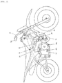
Fig. 1] Fig. 1 is a left side view of an embodiment of a motorcycle according to the invention. - [
Fig. 2] Fig. 2 is a right side view of the same. - [
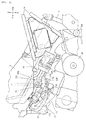
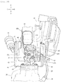
Fig. 3] Fig. 3 is a partially enlarged view ofFig. 1 . - [
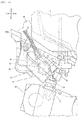
Fig. 4] Fig. 4 is a partially enlarged view ofFig. 3 . - [
Fig. 5] Fig. 5 is a cross-sectional view of a main section. - [
Fig. 6] Fig. 6 is a view that is seen from anarrow 5 direction inFig. 4 . - [
Fig. 7] Fig. 7 is a partially enlarged view ofFig. 2 . - [
Fig. 8] Fig. 8 is a view of an air cleaner that is seen from the front. - [
Fig. 9] Fig. 9 is a view of the air cleaner that is seen from the rear. - [
Fig. 10] Fig. 10 is a partially enlarged cross-sectional view that is taken along 10-10 inFig. 1 . - A description will hereinafter be made on an exemplary embodiment of a motorcycle according to the invention with reference to the drawings. It should be noted that the drawings are seen in a direction that the reference numerals are provided and that, in the following description, front/rear, left/right, and up/down follow directions seen from a driver and are indicated in the drawings upon necessary such that front, rear, left, right, up, and down of a vehicle are respectively indicated as Fr, Rr, L, R, U, and D. In each of the drawings, the same portions or equivalent portions are denoted by the same reference numerals.
- As depicted in
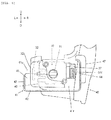
Fig. 1 ,Fig. 4 ,Fig. 5 , andFig. 10 , amotorcycle 1 of this embodiment includes: athrottle body 30 that is provided with athrottle valve 31 for controlling a flow rate of intake air into aninternal combustion engine 20; and anair cleaner 40 for supplying the air to thethrottle body 30. - As depicted in
Fig. 4 andFig. 5 , thethrottle body 30 is arranged at a rear of theair cleaner 40, and anintake port 21 of theinternal combustion engine 20 is arranged at a rear of thethrottle body 30. Theair cleaner 40 includes a throttlebody protecting section 41 for covering at least a lower surface of thethrottle body 30. - According to this motorcycle, the
throttle body 30 is arranged at the rear of theair cleaner 40, theintake port 21 of theinternal combustion engine 20 is arranged at the rear of thethrottle body 30, and theair cleaner 40 includes the throttlebody protecting section 41 for covering at least the lower surface of thethrottle body 30. Accordingly, a front side of thethrottle body 30 can be protected by the air cleaner 40 (depicted is a rear wall (40r) of the air cleaner), and a lower side thereof can be protected by the throttlebody protecting section 41 that is provided in theair cleaner 40. - That is, according to this motorcycle, the
throttle body 30 can be protected by theair cleaner 40 with the throttlebody protecting section 41. Thus, differing from the conventional art, there is no need to prepare the protection cover as an independent component. - Accordingly, the protection cover of the
throttle body 30 is less likely to contribute to an increase in a vehicle weight. In addition, because only theair cleaner 40 has to be attached to a vehicle body, attachability of the protection cover is improved. - As depicted in
Fig. 4 to Fig. 10 , the throttlebody protecting section 41 is in a U shape in a rear view that has: abottom wall 42 for covering the lower surface of thethrottle body 30; andside walls bottom wall 42 and cover the left and right sides of thethrottle body 30, and anupper side 41 u and arear side 41 r thereof are opened. - With such a configuration, while the left and right sides of the
throttle body 30 can respectively be protected by theside walls body protecting section 41, theupper side 41 u and therear side 41 r of the throttlebody protecting section 41 are opened. Thus, after thethrottle body 30 is assembled to the vehicle, theair cleaner 40 can also be assembled by using the above openedsections - As depicted in
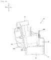
Fig. 6 ,Fig. 7 , andFig. 10 , theright side wall 44 of the throttlebody protecting section 41 covers substantially the entire right sides of athrottle opening sensor 37 and aconnector section 37c thereof that are provided on the right side of thethrottle body 30. - The
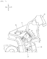
air cleaner 40 is attached to amain frame 10 of the vehicle body via abracket 40b (Fig. 4 ,Fig. 8 ,Fig. 9 ,Fig. 10 ). - As depicted in
Fig. 1 , ahead pipe 11 is provided at a tip of themain frame 10,front forks 5 are supported by thehead pipe 11 in a manner to be steerable by a handlebar 5h, and a front wheel WF is supported at tips of thefront forks 5. - A left and right pair of pivot frames 12 that extends downward is provided in a rear section of the
main frame 10, and aswing arm 13 is swingably supported at apivot 12p by thepivot frame 12. A rear wheel WR is supported at a rear end of theswing arm 13. The rear wheel WR is driven by theinternal combustion engine 20 that is supported by themain frame 10. - 2 and 5 respectively denote a fuel tank and a seat on which a rider is seated. The
seat 5 is supported by arear frame 14 that extends rearward from the rear section of themain frame 10. Abottom frame 15 is provided in front of a lower end of thepivot frame 12, and thebottom frame 15 is provided with astep 15s on which the rider places his/her foot. 16 and 15b (Fig. 2 ) respectively denote a change pedal and a brake pedal. - As depicted in
Fig. 4 andFig. 6 , thethrottle body 30 includes athrottle drum 32 for actuating thethrottle valve 31 in a side section (a left side section in the drawing). - The
throttle drum 32 is arranged to be projected to the side (to the left in the drawing) of theair cleaner 40 in the rear view (Fig. 6 ), and the throttlebody protecting section 41 has afront wall 45 for covering afront section 32f of thethrottle drum 32. - With such a configuration, while a capacity of the
air cleaner 40 can easily be secured by projecting thethrottle drum 32 in the side section of thethrottle body 30 to the side of theair cleaner 40 in the rear view, thethrottle drum 32 can be protected by the throttlebody protecting section 41. - As it is also apparent from
Fig. 4 andFig. 10 , the throttlebody protecting section 41 covers substantially the entire front and lower sides of thethrottle body 30. - In
Fig. 8 andFig. 9 , 40d denotes a dirty-side case for constituting a dirty side of theair cleaner air cleaner internal combustion engine 20 and through which blow-by gas from theinternal combustion engine 20 is returned. - In
Fig. 4 , 33 denotes a throttle wire for a turning operation of thethrottle drum 32, and the throttle wire is connected to athrottle grip 5g (Fig. 2 ) that is operated by the rider.
32c denotes a cover for covering thethrottle drum 32 and holding thethrottle wire 33. - As depicted in
Fig. 5 andFig. 9 , aconnection section 46 to anintake passage 34 of thethrottle body 30 is provided in the rear surface (rear wall) 40r of theair cleaner 40. - With such a configuration, the
intake passage 34 of thethrottle body 30 can directly be connected to theair cleaner 40. Thus, the intake of the air can be smoothed. - As depicted in
Fig. 5 , anexhaust passage 35 of thethrottle body 30 is provided on a downstream side of thethrottle valve 31, and theexhaust passage 35 is connected to theintake port 21 of theinternal combustion engine 20. - A
fuel injection device 36 is provided in theexhaust passage 35 of thethrottle body 30. - In
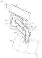
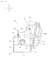
Fig. 3 , 50 denotes a fuel pump that supplies fuel in afuel tank 2 to thefuel injection device 36 via afuel filter 51 and apressure regulator 52.
50h denotes a fuel hose for connecting afuel cock 2c of thefuel tank 2 and thefuel pump fuel pump 50 and thefuel filter fuel filter 51 and thepressure regulator pressure regulator 52 and thefuel injection device 36.
50b denotes a breather hose for keeping the inside of thefuel pump 50 at the atmospheric pressure. One end thereof is connected to thefuel pump 50, and the other end thereof is opened to the inside of thefuel tank 2.
52r denotes a return hose for returning a surplus of the fuel to thefuel tank 2 when pressure of the fuel becomes specified pressure or higher in thepressure regulator 52. One end thereof is connected to thepressure regulator 52, and the other end thereof is opened to the inside of thefuel tank 2. - As depicted in
Fig. 6 ,Fig. 7 , andFig. 10 , on an outer circumferential surface of the throttlebody protecting section 41, the throttlebody protecting section 41 has, awire positioning section 47 for positioning a high-voltage wire 23 that leads to anignition coil 22.
With such a configuration, the high-voltage wire 23, which leads to theignition coil 22, can be prevented from contacting the other components.
24 denotes an ignition plug that is connected to theignition coil 22 by the high-voltage wire 23. - The
wire positioning section 47 is provided at a position that is in front of theignition coil 22 and is separated from theignition coil 22. - With such a configuration, a state where the high-
voltage wire 23 is bent immediately after being drawn out of theignition coil 22 can be prevented. Thus, application of a load on theignition coil 22 can be restricted. - The
wire positioning section 47 has arib 47r that is provided over anupper end 41 c and alower end 41 b of the outer circumferential surface of the throttlebody protecting section 41. - With such a configuration, the high-
voltage wire 23 can be positioned in a manner to stretch vertically and thus can further reliably be positioned. - The embodiment of the invention has been described so far. However, the invention is not limited to the above embodiment and can appropriately be modified within the scope of the gist of the invention.
-
- 20:
- internal combustion engine
- 21:
- intake port
- 22:
- ignition coil
- 23:
- high-voltage wire
- 30:
- throttle body
- 31:
- throttle valve
- 32:
- throttle drum
- 40:
- air cleaner
- 41:
- throttle body protecting section
- 42:
- bottom wall
- 43, 44:
- side wall
- 45:
- front wall
- 46:
- connection section
- 47:
- wire positioning section
- 47r:
- rib
Claims (7)
- A motorcycle comprising:a throttle body (30) that is provided with a throttle valve (31) for controlling a flow rate of intake air into an internal combustion engine (20); andan air cleaner (40) for supplying air to the throttle body (30), whereinthe throttle body (30) is arranged at a rear of the air cleaner (40), an intake port (21) of the internal combustion engine (20) is arranged at a rear of the throttle body (30), and the air cleaner (40) includes a throttle body protecting section (41) for covering at least a lower surface of the throttle body (30).
- A motorcycle according to claim 1, wherein
the throttle body protecting section (41) is in a U shape in a rear view that has: a bottom wall (42) for covering the lower surface of the throttle body (30); and side walls (43, 44) that respectively extend upward from left and right of the bottom wall (42) and cover left and right sides of the throttle body (30), and an upper side and a rear side thereof are opened. - A motorcycle according to claim 1 or 2, wherein
the throttle body (30) includes a throttle drum (32) for actuating the throttle valve (31) in a side section,
the throttle drum (32) is arranged to be projected to a side of the air cleaner (40) in the rear view, and
the throttle body protecting section (41) has a front wall (45) for protecting a front section (32f) of the throttle drum (32). - A motorcycle according to any one of claims 1 to 3, wherein
a connection section (46) to an intake passage (34) of the throttle body (30) is provided in a rear surface (40r) of the air cleaner (40). - A motorcycle according to any one of claims 1 to 4, wherein
the throttle body protecting section (41) has, on an outer circumferential surface of the throttle body protecting section (41), a wire positioning section (47) for positioning a high-voltage wire (23) that leads to an ignition coil (22). - A motorcycle according to claim 5, wherein
the wire positioning section (47) is provided at a position that is in front of the ignition coil (22) and is separated from the ignition coil (22). - A motorcycle according to claim 5 or 6, wherein
the wire positioning section (47) has a rib (47r) that is provided over an upper end and a lower end of the outer circumferential surface of the throttle body protecting section (41 ).
Applications Claiming Priority (1)
| Application Number | Priority Date | Filing Date | Title |
|---|---|---|---|
| JP2015057667A JP6096234B2 (en) | 2015-03-20 | 2015-03-20 | Motorcycle |
Publications (3)
| Publication Number | Publication Date |
|---|---|
| EP3069984A2 true EP3069984A2 (en) | 2016-09-21 |
| EP3069984A3 EP3069984A3 (en) | 2016-09-28 |
| EP3069984B1 EP3069984B1 (en) | 2019-02-13 |
Family
ID=55446676
Family Applications (1)
| Application Number | Title | Priority Date | Filing Date |
|---|---|---|---|
| EP16157672.3A Not-in-force EP3069984B1 (en) | 2015-03-20 | 2016-02-26 | Motorcycle |
Country Status (5)
| Country | Link |
|---|---|
| US (1) | US9845784B2 (en) |
| EP (1) | EP3069984B1 (en) |
| JP (1) | JP6096234B2 (en) |
| CN (1) | CN105986908A (en) |
| AU (1) | AU2016200436B2 (en) |
Families Citing this family (1)
| Publication number | Priority date | Publication date | Assignee | Title |
|---|---|---|---|---|
| JP6472482B2 (en) * | 2017-04-28 | 2019-02-20 | 本田技研工業株式会社 | Saddle riding |
Citations (1)
| Publication number | Priority date | Publication date | Assignee | Title |
|---|---|---|---|---|
| JP2007177682A (en) | 2005-12-27 | 2007-07-12 | Honda Motor Co Ltd | Internal combustion engine for vehicle provided with protection cover for throttle body |
Family Cites Families (10)
| Publication number | Priority date | Publication date | Assignee | Title |
|---|---|---|---|---|
| DE1135241B (en) * | 1954-04-17 | 1962-08-23 | Kreidler Dipl Ing Alfred | Arrangement of an intake line for carburettor engines |
| JP4021339B2 (en) * | 2003-02-12 | 2007-12-12 | 本田技研工業株式会社 | Fuel supply system for motorcycles |
| JP2005076602A (en) * | 2003-09-03 | 2005-03-24 | Honda Motor Co Ltd | Throttle body protecting device |
| US7104236B2 (en) * | 2003-09-30 | 2006-09-12 | Honda Motor Co., Ltd. | Intake air management apparatus for a vehicle, and motorcycle including same |
| JP2006037897A (en) * | 2004-07-29 | 2006-02-09 | Honda Motor Co Ltd | Intake device for vehicle engine |
| JP4785581B2 (en) * | 2006-03-22 | 2011-10-05 | 本田技研工業株式会社 | Electrical component support structure for motorcycles |
| JP5339603B2 (en) * | 2009-03-30 | 2013-11-13 | 本田技研工業株式会社 | Motorcycle |
| JP2011144724A (en) * | 2010-01-13 | 2011-07-28 | Honda Motor Co Ltd | Saddle-riding type vehicle |
| JP5913083B2 (en) * | 2012-12-26 | 2016-04-27 | 本田技研工業株式会社 | Vehicle intake passage structure |
| JP5925261B2 (en) * | 2014-08-27 | 2016-05-25 | 本田技研工業株式会社 | Vehicle intake system |
-
2015
- 2015-03-20 JP JP2015057667A patent/JP6096234B2/en active Active
-
2016
- 2016-01-27 AU AU2016200436A patent/AU2016200436B2/en not_active Ceased
- 2016-02-26 EP EP16157672.3A patent/EP3069984B1/en not_active Not-in-force
- 2016-03-14 US US15/068,895 patent/US9845784B2/en active Active
- 2016-03-17 CN CN201610152565.0A patent/CN105986908A/en active Pending
Patent Citations (1)
| Publication number | Priority date | Publication date | Assignee | Title |
|---|---|---|---|---|
| JP2007177682A (en) | 2005-12-27 | 2007-07-12 | Honda Motor Co Ltd | Internal combustion engine for vehicle provided with protection cover for throttle body |
Also Published As
| Publication number | Publication date |
|---|---|
| EP3069984B1 (en) | 2019-02-13 |
| JP6096234B2 (en) | 2017-03-15 |
| EP3069984A3 (en) | 2016-09-28 |
| AU2016200436B2 (en) | 2017-03-23 |
| US9845784B2 (en) | 2017-12-19 |
| CN105986908A (en) | 2016-10-05 |
| AU2016200436A1 (en) | 2016-10-06 |
| US20160273460A1 (en) | 2016-09-22 |
| JP2016176417A (en) | 2016-10-06 |
Similar Documents
| Publication | Publication Date | Title |
|---|---|---|
| EP2644489B1 (en) | Saddle-type vehicle | |
| US10131396B2 (en) | Saddled vehicle | |
| JP5775560B2 (en) | Saddle riding | |
| CN106470897B (en) | The air inlet pipe of two-wheeled motor vehicle | |
| US9470170B2 (en) | Fuel injection device for engine of motorcycle | |
| JP5546897B2 (en) | Intake air temperature sensor arrangement structure for motorcycles | |
| EP3069984B1 (en) | Motorcycle | |
| JP5507359B2 (en) | Evaporative fuel processing equipment for motorcycles | |
| CN101929391B (en) | Coupler configuration for throttle body | |
| US10550755B2 (en) | Saddle type vehicle having water cooled engine | |
| JP5924975B2 (en) | Saddle riding | |
| US10954833B2 (en) | Air cleaner | |
| CN1120292C (en) | Secondary air supply device of exhaust system of motorbike | |
| BR112021011048B1 (en) | REGULATOR VALVE ARRANGEMENT STRUCTURE | |
| JP6269081B2 (en) | Injector mounting structure | |
| AU2016200483B2 (en) | Fuel supply device of motorcycle | |
| JP5841871B2 (en) | Motorcycle exhaust system | |
| US9316177B2 (en) | Saddle-ride type vehicle | |
| BR102018072472B1 (en) | VEHICLE OF THE TYPE TO ASSEMBLE |
Legal Events
| Date | Code | Title | Description |
|---|---|---|---|
| PUAI | Public reference made under article 153(3) epc to a published international application that has entered the european phase |
Free format text: ORIGINAL CODE: 0009012 |
|
| PUAL | Search report despatched |
Free format text: ORIGINAL CODE: 0009013 |
|
| 17P | Request for examination filed |
Effective date: 20160226 |
|
| AK | Designated contracting states |
Kind code of ref document: A2 Designated state(s): AL AT BE BG CH CY CZ DE DK EE ES FI FR GB GR HR HU IE IS IT LI LT LU LV MC MK MT NL NO PL PT RO RS SE SI SK SM TR |
|
| AX | Request for extension of the european patent |
Extension state: BA ME |
|
| AK | Designated contracting states |
Kind code of ref document: A3 Designated state(s): AL AT BE BG CH CY CZ DE DK EE ES FI FR GB GR HR HU IE IS IT LI LT LU LV MC MK MT NL NO PL PT RO RS SE SI SK SM TR |
|
| AX | Request for extension of the european patent |
Extension state: BA ME |
|
| RIC1 | Information provided on ipc code assigned before grant |
Ipc: B62M 7/02 20060101AFI20160825BHEP Ipc: F02M 35/16 20060101ALI20160825BHEP Ipc: B62J 37/00 20060101ALI20160825BHEP Ipc: B62J 23/00 20060101ALN20160825BHEP |
|
| GRAP | Despatch of communication of intention to grant a patent |
Free format text: ORIGINAL CODE: EPIDOSNIGR1 |
|
| STAA | Information on the status of an ep patent application or granted ep patent |
Free format text: STATUS: GRANT OF PATENT IS INTENDED |
|
| RIC1 | Information provided on ipc code assigned before grant |
Ipc: B62M 7/02 20060101AFI20180110BHEP Ipc: F02M 35/16 20060101ALI20180110BHEP Ipc: B62J 23/00 20060101ALN20180110BHEP Ipc: B62J 37/00 20060101ALI20180110BHEP |
|
| RIC1 | Information provided on ipc code assigned before grant |
Ipc: B62J 23/00 20060101ALN20180112BHEP Ipc: B62J 37/00 20060101ALI20180112BHEP Ipc: F02M 35/16 20060101ALI20180112BHEP Ipc: B62M 7/02 20060101AFI20180112BHEP |
|
| INTG | Intention to grant announced |
Effective date: 20180201 |
|
| GRAS | Grant fee paid |
Free format text: ORIGINAL CODE: EPIDOSNIGR3 |
|
| GRAA | (expected) grant |
Free format text: ORIGINAL CODE: 0009210 |
|
| STAA | Information on the status of an ep patent application or granted ep patent |
Free format text: STATUS: THE PATENT HAS BEEN GRANTED |
|
| AK | Designated contracting states |
Kind code of ref document: B1 Designated state(s): AL AT BE BG CH CY CZ DE DK EE ES FI FR GB GR HR HU IE IS IT LI LT LU LV MC MK MT NL NO PL PT RO RS SE SI SK SM TR |
|
| REG | Reference to a national code |
Ref country code: GB Ref legal event code: FG4D |
|
| REG | Reference to a national code |
Ref country code: CH Ref legal event code: EP Ref country code: AT Ref legal event code: REF Ref document number: 1096033 Country of ref document: AT Kind code of ref document: T Effective date: 20190215 |
|
| REG | Reference to a national code |
Ref country code: IE Ref legal event code: FG4D |
|
| REG | Reference to a national code |
Ref country code: DE Ref legal event code: R096 Ref document number: 602016009864 Country of ref document: DE |
|
| PGFP | Annual fee paid to national office [announced via postgrant information from national office to epo] |
Ref country code: IT Payment date: 20190228 Year of fee payment: 4 |
|
| REG | Reference to a national code |
Ref country code: LT Ref legal event code: MG4D |
|
| REG | Reference to a national code |
Ref country code: NL Ref legal event code: MP Effective date: 20190213 |
|
| PG25 | Lapsed in a contracting state [announced via postgrant information from national office to epo] |
Ref country code: PT Free format text: LAPSE BECAUSE OF FAILURE TO SUBMIT A TRANSLATION OF THE DESCRIPTION OR TO PAY THE FEE WITHIN THE PRESCRIBED TIME-LIMIT Effective date: 20190613 Ref country code: SE Free format text: LAPSE BECAUSE OF FAILURE TO SUBMIT A TRANSLATION OF THE DESCRIPTION OR TO PAY THE FEE WITHIN THE PRESCRIBED TIME-LIMIT Effective date: 20190213 Ref country code: NO Free format text: LAPSE BECAUSE OF FAILURE TO SUBMIT A TRANSLATION OF THE DESCRIPTION OR TO PAY THE FEE WITHIN THE PRESCRIBED TIME-LIMIT Effective date: 20190513 Ref country code: FI Free format text: LAPSE BECAUSE OF FAILURE TO SUBMIT A TRANSLATION OF THE DESCRIPTION OR TO PAY THE FEE WITHIN THE PRESCRIBED TIME-LIMIT Effective date: 20190213 Ref country code: LT Free format text: LAPSE BECAUSE OF FAILURE TO SUBMIT A TRANSLATION OF THE DESCRIPTION OR TO PAY THE FEE WITHIN THE PRESCRIBED TIME-LIMIT Effective date: 20190213 Ref country code: NL Free format text: LAPSE BECAUSE OF FAILURE TO SUBMIT A TRANSLATION OF THE DESCRIPTION OR TO PAY THE FEE WITHIN THE PRESCRIBED TIME-LIMIT Effective date: 20190213 |
|
| PGFP | Annual fee paid to national office [announced via postgrant information from national office to epo] |
Ref country code: DE Payment date: 20190418 Year of fee payment: 4 |
|
| PG25 | Lapsed in a contracting state [announced via postgrant information from national office to epo] |
Ref country code: BG Free format text: LAPSE BECAUSE OF FAILURE TO SUBMIT A TRANSLATION OF THE DESCRIPTION OR TO PAY THE FEE WITHIN THE PRESCRIBED TIME-LIMIT Effective date: 20190513 Ref country code: RS Free format text: LAPSE BECAUSE OF FAILURE TO SUBMIT A TRANSLATION OF THE DESCRIPTION OR TO PAY THE FEE WITHIN THE PRESCRIBED TIME-LIMIT Effective date: 20190213 Ref country code: LV Free format text: LAPSE BECAUSE OF FAILURE TO SUBMIT A TRANSLATION OF THE DESCRIPTION OR TO PAY THE FEE WITHIN THE PRESCRIBED TIME-LIMIT Effective date: 20190213 Ref country code: IS Free format text: LAPSE BECAUSE OF FAILURE TO SUBMIT A TRANSLATION OF THE DESCRIPTION OR TO PAY THE FEE WITHIN THE PRESCRIBED TIME-LIMIT Effective date: 20190613 Ref country code: HR Free format text: LAPSE BECAUSE OF FAILURE TO SUBMIT A TRANSLATION OF THE DESCRIPTION OR TO PAY THE FEE WITHIN THE PRESCRIBED TIME-LIMIT Effective date: 20190213 Ref country code: GR Free format text: LAPSE BECAUSE OF FAILURE TO SUBMIT A TRANSLATION OF THE DESCRIPTION OR TO PAY THE FEE WITHIN THE PRESCRIBED TIME-LIMIT Effective date: 20190514 |
|
| PGFP | Annual fee paid to national office [announced via postgrant information from national office to epo] |
Ref country code: FR Payment date: 20190405 Year of fee payment: 4 |
|
| REG | Reference to a national code |
Ref country code: AT Ref legal event code: MK05 Ref document number: 1096033 Country of ref document: AT Kind code of ref document: T Effective date: 20190213 |
|
| REG | Reference to a national code |
Ref country code: CH Ref legal event code: PL |
|
| PG25 | Lapsed in a contracting state [announced via postgrant information from national office to epo] |
Ref country code: SK Free format text: LAPSE BECAUSE OF FAILURE TO SUBMIT A TRANSLATION OF THE DESCRIPTION OR TO PAY THE FEE WITHIN THE PRESCRIBED TIME-LIMIT Effective date: 20190213 Ref country code: RO Free format text: LAPSE BECAUSE OF FAILURE TO SUBMIT A TRANSLATION OF THE DESCRIPTION OR TO PAY THE FEE WITHIN THE PRESCRIBED TIME-LIMIT Effective date: 20190213 Ref country code: EE Free format text: LAPSE BECAUSE OF FAILURE TO SUBMIT A TRANSLATION OF THE DESCRIPTION OR TO PAY THE FEE WITHIN THE PRESCRIBED TIME-LIMIT Effective date: 20190213 Ref country code: DK Free format text: LAPSE BECAUSE OF FAILURE TO SUBMIT A TRANSLATION OF THE DESCRIPTION OR TO PAY THE FEE WITHIN THE PRESCRIBED TIME-LIMIT Effective date: 20190213 Ref country code: LU Free format text: LAPSE BECAUSE OF NON-PAYMENT OF DUE FEES Effective date: 20190226 Ref country code: AL Free format text: LAPSE BECAUSE OF FAILURE TO SUBMIT A TRANSLATION OF THE DESCRIPTION OR TO PAY THE FEE WITHIN THE PRESCRIBED TIME-LIMIT Effective date: 20190213 Ref country code: ES Free format text: LAPSE BECAUSE OF FAILURE TO SUBMIT A TRANSLATION OF THE DESCRIPTION OR TO PAY THE FEE WITHIN THE PRESCRIBED TIME-LIMIT Effective date: 20190213 Ref country code: CZ Free format text: LAPSE BECAUSE OF FAILURE TO SUBMIT A TRANSLATION OF THE DESCRIPTION OR TO PAY THE FEE WITHIN THE PRESCRIBED TIME-LIMIT Effective date: 20190213 |
|
| REG | Reference to a national code |
Ref country code: DE Ref legal event code: R097 Ref document number: 602016009864 Country of ref document: DE |
|
| REG | Reference to a national code |
Ref country code: BE Ref legal event code: MM Effective date: 20190228 |
|
| REG | Reference to a national code |
Ref country code: IE Ref legal event code: MM4A |
|
| PG25 | Lapsed in a contracting state [announced via postgrant information from national office to epo] |
Ref country code: SM Free format text: LAPSE BECAUSE OF FAILURE TO SUBMIT A TRANSLATION OF THE DESCRIPTION OR TO PAY THE FEE WITHIN THE PRESCRIBED TIME-LIMIT Effective date: 20190213 Ref country code: PL Free format text: LAPSE BECAUSE OF FAILURE TO SUBMIT A TRANSLATION OF THE DESCRIPTION OR TO PAY THE FEE WITHIN THE PRESCRIBED TIME-LIMIT Effective date: 20190213 |
|
| PLBE | No opposition filed within time limit |
Free format text: ORIGINAL CODE: 0009261 |
|
| STAA | Information on the status of an ep patent application or granted ep patent |
Free format text: STATUS: NO OPPOSITION FILED WITHIN TIME LIMIT |
|
| PG25 | Lapsed in a contracting state [announced via postgrant information from national office to epo] |
Ref country code: CH Free format text: LAPSE BECAUSE OF NON-PAYMENT OF DUE FEES Effective date: 20190228 Ref country code: AT Free format text: LAPSE BECAUSE OF FAILURE TO SUBMIT A TRANSLATION OF THE DESCRIPTION OR TO PAY THE FEE WITHIN THE PRESCRIBED TIME-LIMIT Effective date: 20190213 Ref country code: MC Free format text: LAPSE BECAUSE OF FAILURE TO SUBMIT A TRANSLATION OF THE DESCRIPTION OR TO PAY THE FEE WITHIN THE PRESCRIBED TIME-LIMIT Effective date: 20190213 Ref country code: LI Free format text: LAPSE BECAUSE OF NON-PAYMENT OF DUE FEES Effective date: 20190228 |
|
| 26N | No opposition filed |
Effective date: 20191114 |
|
| PG25 | Lapsed in a contracting state [announced via postgrant information from national office to epo] |
Ref country code: IE Free format text: LAPSE BECAUSE OF NON-PAYMENT OF DUE FEES Effective date: 20190226 |
|
| PG25 | Lapsed in a contracting state [announced via postgrant information from national office to epo] |
Ref country code: BE Free format text: LAPSE BECAUSE OF NON-PAYMENT OF DUE FEES Effective date: 20190228 Ref country code: SI Free format text: LAPSE BECAUSE OF FAILURE TO SUBMIT A TRANSLATION OF THE DESCRIPTION OR TO PAY THE FEE WITHIN THE PRESCRIBED TIME-LIMIT Effective date: 20190213 |
|
| PG25 | Lapsed in a contracting state [announced via postgrant information from national office to epo] |
Ref country code: TR Free format text: LAPSE BECAUSE OF FAILURE TO SUBMIT A TRANSLATION OF THE DESCRIPTION OR TO PAY THE FEE WITHIN THE PRESCRIBED TIME-LIMIT Effective date: 20190213 |
|
| PG25 | Lapsed in a contracting state [announced via postgrant information from national office to epo] |
Ref country code: MT Free format text: LAPSE BECAUSE OF NON-PAYMENT OF DUE FEES Effective date: 20190226 |
|
| REG | Reference to a national code |
Ref country code: DE Ref legal event code: R119 Ref document number: 602016009864 Country of ref document: DE |
|
| GBPC | Gb: european patent ceased through non-payment of renewal fee |
Effective date: 20200226 |
|
| PG25 | Lapsed in a contracting state [announced via postgrant information from national office to epo] |
Ref country code: DE Free format text: LAPSE BECAUSE OF NON-PAYMENT OF DUE FEES Effective date: 20200901 Ref country code: FR Free format text: LAPSE BECAUSE OF NON-PAYMENT OF DUE FEES Effective date: 20200229 Ref country code: GB Free format text: LAPSE BECAUSE OF NON-PAYMENT OF DUE FEES Effective date: 20200226 |
|
| PG25 | Lapsed in a contracting state [announced via postgrant information from national office to epo] |
Ref country code: CY Free format text: LAPSE BECAUSE OF FAILURE TO SUBMIT A TRANSLATION OF THE DESCRIPTION OR TO PAY THE FEE WITHIN THE PRESCRIBED TIME-LIMIT Effective date: 20190213 |
|
| PG25 | Lapsed in a contracting state [announced via postgrant information from national office to epo] |
Ref country code: HU Free format text: LAPSE BECAUSE OF FAILURE TO SUBMIT A TRANSLATION OF THE DESCRIPTION OR TO PAY THE FEE WITHIN THE PRESCRIBED TIME-LIMIT; INVALID AB INITIO Effective date: 20160226 |
|
| PG25 | Lapsed in a contracting state [announced via postgrant information from national office to epo] |
Ref country code: IT Free format text: LAPSE BECAUSE OF NON-PAYMENT OF DUE FEES Effective date: 20200226 |
|
| PG25 | Lapsed in a contracting state [announced via postgrant information from national office to epo] |
Ref country code: MK Free format text: LAPSE BECAUSE OF FAILURE TO SUBMIT A TRANSLATION OF THE DESCRIPTION OR TO PAY THE FEE WITHIN THE PRESCRIBED TIME-LIMIT Effective date: 20190213 |