EP3069980A1 - Radiator arrangement structure for saddle-ride type vehicles - Google Patents
Radiator arrangement structure for saddle-ride type vehicles Download PDFInfo
- Publication number
- EP3069980A1 EP3069980A1 EP16151682.8A EP16151682A EP3069980A1 EP 3069980 A1 EP3069980 A1 EP 3069980A1 EP 16151682 A EP16151682 A EP 16151682A EP 3069980 A1 EP3069980 A1 EP 3069980A1
- Authority
- EP
- European Patent Office
- Prior art keywords
- radiator
- saddle
- cooling fan
- ride type
- type vehicle
- Prior art date
- Legal status (The legal status is an assumption and is not a legal conclusion. Google has not performed a legal analysis and makes no representation as to the accuracy of the status listed.)
- Granted
Links
Images


Classifications
-
- F—MECHANICAL ENGINEERING; LIGHTING; HEATING; WEAPONS; BLASTING
- F01—MACHINES OR ENGINES IN GENERAL; ENGINE PLANTS IN GENERAL; STEAM ENGINES
- F01P—COOLING OF MACHINES OR ENGINES IN GENERAL; COOLING OF INTERNAL-COMBUSTION ENGINES
- F01P11/00—Component parts, details, or accessories not provided for in, or of interest apart from, groups F01P1/00 - F01P9/00
- F01P11/04—Arrangements of liquid pipes or hoses
-
- B—PERFORMING OPERATIONS; TRANSPORTING
- B62—LAND VEHICLES FOR TRAVELLING OTHERWISE THAN ON RAILS
- B62K—CYCLES; CYCLE FRAMES; CYCLE STEERING DEVICES; RIDER-OPERATED TERMINAL CONTROLS SPECIALLY ADAPTED FOR CYCLES; CYCLE AXLE SUSPENSIONS; CYCLE SIDE-CARS, FORECARS, OR THE LIKE
- B62K11/00—Motorcycles, engine-assisted cycles or motor scooters with one or two wheels
-
- B—PERFORMING OPERATIONS; TRANSPORTING
- B60—VEHICLES IN GENERAL
- B60K—ARRANGEMENT OR MOUNTING OF PROPULSION UNITS OR OF TRANSMISSIONS IN VEHICLES; ARRANGEMENT OR MOUNTING OF PLURAL DIVERSE PRIME-MOVERS IN VEHICLES; AUXILIARY DRIVES FOR VEHICLES; INSTRUMENTATION OR DASHBOARDS FOR VEHICLES; ARRANGEMENTS IN CONNECTION WITH COOLING, AIR INTAKE, GAS EXHAUST OR FUEL SUPPLY OF PROPULSION UNITS IN VEHICLES
- B60K11/00—Arrangement in connection with cooling of propulsion units
- B60K11/02—Arrangement in connection with cooling of propulsion units with liquid cooling
- B60K11/04—Arrangement or mounting of radiators, radiator shutters, or radiator blinds
-
- B—PERFORMING OPERATIONS; TRANSPORTING
- B62—LAND VEHICLES FOR TRAVELLING OTHERWISE THAN ON RAILS
- B62K—CYCLES; CYCLE FRAMES; CYCLE STEERING DEVICES; RIDER-OPERATED TERMINAL CONTROLS SPECIALLY ADAPTED FOR CYCLES; CYCLE AXLE SUSPENSIONS; CYCLE SIDE-CARS, FORECARS, OR THE LIKE
- B62K11/00—Motorcycles, engine-assisted cycles or motor scooters with one or two wheels
- B62K11/02—Frames
- B62K11/04—Frames characterised by the engine being between front and rear wheels
-
- B—PERFORMING OPERATIONS; TRANSPORTING
- B62—LAND VEHICLES FOR TRAVELLING OTHERWISE THAN ON RAILS
- B62M—RIDER PROPULSION OF WHEELED VEHICLES OR SLEDGES; POWERED PROPULSION OF SLEDGES OR SINGLE-TRACK CYCLES; TRANSMISSIONS SPECIALLY ADAPTED FOR SUCH VEHICLES
- B62M7/00—Motorcycles characterised by position of motor or engine
- B62M7/02—Motorcycles characterised by position of motor or engine with engine between front and rear wheels
-
- F—MECHANICAL ENGINEERING; LIGHTING; HEATING; WEAPONS; BLASTING
- F01—MACHINES OR ENGINES IN GENERAL; ENGINE PLANTS IN GENERAL; STEAM ENGINES
- F01P—COOLING OF MACHINES OR ENGINES IN GENERAL; COOLING OF INTERNAL-COMBUSTION ENGINES
- F01P1/00—Air cooling
- F01P1/06—Arrangements for cooling other engine or machine parts
-
- F—MECHANICAL ENGINEERING; LIGHTING; HEATING; WEAPONS; BLASTING
- F01—MACHINES OR ENGINES IN GENERAL; ENGINE PLANTS IN GENERAL; STEAM ENGINES
- F01P—COOLING OF MACHINES OR ENGINES IN GENERAL; COOLING OF INTERNAL-COMBUSTION ENGINES
- F01P3/00—Liquid cooling
- F01P3/20—Cooling circuits not specific to a single part of engine or machine
-
- F—MECHANICAL ENGINEERING; LIGHTING; HEATING; WEAPONS; BLASTING
- F01—MACHINES OR ENGINES IN GENERAL; ENGINE PLANTS IN GENERAL; STEAM ENGINES
- F01P—COOLING OF MACHINES OR ENGINES IN GENERAL; COOLING OF INTERNAL-COMBUSTION ENGINES
- F01P5/00—Pumping cooling-air or liquid coolants
- F01P5/02—Pumping cooling-air; Arrangements of cooling-air pumps, e.g. fans or blowers
Definitions
- the present invention relates to a radiator arrangement structure of a saddle-ride type vehicle.
- Some saddle-ride type vehicles have a radiator placed downward of the rider seat and upward of a rear fender, one of which is disclosed in, for example, JP-A No. 2009-001264 ( Fig. 1 , Fig. 2 ) listed later.
- the effective area of the radiator core is reduced because a cooling fan is located next to the rearward end of the radiator, and further the size of an exhaust duct is increased in order to protect the cooling fan from outside foreign substances such as flying substances thrown up by the rear wheel and/or the like.
- an object of the present invention is to provide a radiator arrangement structure of a saddle-ride type vehicle that enables a compact mounting space, a reduction in seat height and an enhancement in cooling performance.
- the present invention has been made in light of the above-descried related art, and provides a radiator arrangement structure of a saddle-ride type vehicle equipped with a water-cooled internal combustion engine.
- a radiator is placed to face a front portion of a rear fender and to incline rearward along the rear fender; and a cooling fan is placed forward of the radiator in a forward inclined position.
- a feature of the invention described in claim 2 is that, in the radiator arrangement structure for a saddle-ride type vehicle according to claim 1, in side view, the cooling fan and the radiator are housed in a V-shaped region defined by a main frame and the rear fender, in such a manner as to increase a distance between the cooling fan and the radiator toward their top ends.
- a feature of the invention described in claim 3 is that, in the radiator arrangement structure for a saddle-ride type vehicle according to claim 2, the radiator is placed directly underneath a rider seat.
- a feature of the invention described in claim 4 is that, in the radiator arrangement structure for a saddle-ride type vehicle according to claim 2 or 3, the cooling fan is placed directly underneath a rider seat and covered with a body cover.
- a feature of the invention described in claim 5 is that, in the radiator arrangement structure for a saddle-ride type vehicle according to claim 4, a fan shroud surrounding the cooling fan has a vent inclined forward.
- a feature of the invention described in claim 6 is that, in the radiator arrangement structure for a saddle-ride type vehicle according to any one of claims 3 to 4, a part of the radiator extends upward beyond seat rails in side view.
- the radiator is placed to incline rearward along the front portion of the rear fender, and the cooling fan is placed forward of the radiator to incline forward. Because of this, the cooling fan and the radiator are located to increase the space between them gradually toward their top ends.
- the size in the height direction of the radiator and the cooling fan is reduced to achieve compact layout. Further, placing the cooling fan in an inclined position relative to the radiator causes cooling air to readily hit the entire radiator core, leading to enhancement in cooling performance.
- the cooling fan is placed in front of the radiator, the cooling fan is located at a distance from the rear wheel in the forward direction. Therefore, as compared with the case of the cooling fan being arranged rearward of the radiator, the cooling fan can be located to prevent easy entry of foreign substances from outside.
- the rider seat is placed above the V-shaped region, so that room under the rider seat is adequate to house components arranged therein to be spaced gradually from each other toward their tops. Therefore, the cooling fan and the radiator can be arranged in a compact manner under the rider seat.
- the radiator is inclined rearward along the rear fender, the vertical installed height of the radiator can be reduced. This minimizes the projection of the radiator from the seat reals, enabling a reduction in height of the rider seat.
- the radiator is positioned to incline rearward to minimize the height of the rider seat, and additionally, the radiator core ranges between the seat rails to increase the cooling area of the radiator core.
- a radiator arrangement structure of a saddle-ride type vehicle according to one embodiment of the present invention is described with reference to Fig. 1 to Fig. 3 .
- the vehicle in the embodiment is a saddle-ride type vehicle, in particular, a motorcycle.
- arrow FR shows a forward direction of the vehicle
- arrow LH shows a leftward direction of the vehicle
- arrow RH shows a rightward diction of the vehicle
- arrow UP shows an upward direction of the vehicle.
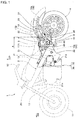
- Fig. 1 is a left side view of an essential part of a motorcycle having the radiator arrangement structure of the saddle-ride type vehicle according to one embodiment of the present invention.
- Fig. 1 illustrates a motorcycle ("saddle-ride type vehicle" in the present invention) 1, in which a body cover 10 is indicated simply by a two-dot chain line with some parts omitted, and also the front section of the vehicle, a power unit 3, and the like are simply indicated by two-dot chain lines, and only essential parts of the rear section of the vehicle are shown.
- a body cover 10 is indicated simply by a two-dot chain line with some parts omitted, and also the front section of the vehicle, a power unit 3, and the like are simply indicated by two-dot chain lines, and only essential parts of the rear section of the vehicle are shown.
- a body frame 2 of the motorcycle 1 includes a main frame 21 extending from an upper front point of the vehicle body toward a rearward and downward direction, and a front fork 13 with a lower end to which a front wheel 11 is journaled and an upper end to which a handlebar 12 is secured is steerably supported by a head pipe 20 that is attached to a front end of the main frame 21.
- the power unit 3 driving a rear wheel 14 is placed in a space under the main frame 21.
- the power unit 3 is mounted to the main frame 21 through a plurality of hanger members 21a.
- the power unit 3 includes a water-cooled internal combustion engine 30 and a transmission 35, and has an output shaft connected to the rear wheel 14 through a not-shown drive shaft mounted along the swing arm 15 to transfer the rotational power to the rear wheel 14.
- the main frames 21 are provided in a left-right pair and are spread apart in the left-right directions in plan view as extending rearward. Then, a fuel tank 16 is supported to be laid on between the left and right main frames 21. Also, left and right seat rails 23 are provided to extend upwardly toward the rear respectively from upper portions of the rear ends of the left and right main frames 21, and back stays 24 are provided respectively for connection between lower portions of the rear ends of the left and right main frames 21 and rearward portions of the left and right seat rails 23. A rider seat 17A and a pillion passenger seat 17B are mounted on the seat rails 23. Imaginary lines A in Fig. 1 indicate the range and length of the rider seat 17A in the vehicle-longitudinal direction.
- the members on either left or right side are connected to each other by connecting members as illustrated in Fig. 3 , and a reinforcing frame 25 is placed between a front portion of the seat rail 23 and the back stay 24.
- a rear cushion unit is placed between an upper portion of the rear end of the main frame 21 and the swing arm 15.
- a rear cover 10a of the body cover 10 is mounted downward of a rear portion of the rider seat 17A and pillion passenger seat 17B and above the rear wheel 14 so as to cover the rear portion of the seat rails 23 and the back stays 24.
- a side cover 10b of the body cover 10 is mounted downward of a front portion of the rider seat 17A so as to cover the front portion of the seat rail 23 and an area downward of the seat rail 23.
- a rear fender 18 is attached to the swing arm 15 to cover the upper surface of the rear wheel 14, so that the rear fender 18 vertically swings together with the rear wheel 14.
- the main frame 21 is oriented downward to the rear as indicated by imaginary line B in Fig. 2 , and, in a position rearward of this, a front portion of the rear fender 18 is oriented upward to the rear as indicated by imaginary line E in Fig. 2 .
- the main frame 21 and the rear fender 18 form a V shape as formed by imaginary lines B and E in side view.
- a radiator 4 and a cooling fan 6 for cooling the internal combustion engine 30 are mounted in the V-shaped space in side view.
- the radiator 4 is arranged to incline rearward along the rear fender 18 while facing the front portion of the rear fender 18 as indicated by imaginary line D in Fig. 2 .
- the radiator 4 is mounted to the body frame 2 with a radiator mounting stay 26 which is attached to the seat rails 23 and the reinforcing frames 25 (see Fig. 3 ).
- the cooling fan 6 in front of the radiator 4, the cooling fan 6 is arranged to incline forward as indicated by imaginary line C in Fig. 2 , and a fan shroud 60 surrounding the cooling fan 6 is mounted to the body frame 2 through a fan mounting stay 27 with a fan mounting bolt 60c (see Fig. 3 ).
- a cooling-air duct 61 is connected between the fan shroud 60 and the radiator 4, so that cooling air is delivered to the radiator 4 with reliability.
- the radiator 4 cooling the coolant in the internal combustion engine 30 includes an upper tank 41, a lower tank 42, and a rectangular radiator core 40 formed between the upper tank 41 and the lower tank 42.
- the radiator core 40 includes a plurality of flat coolant tubes, not shown, which connect between the upper tank 41 and the lower tank 42, and a plurality of corrugated fins, not shown, which connect between adjacent coolant tubes.
- a coolant returning port 44 in the lower tank 42 is connected through a radiator lower hose 46 to the internal combustion engine 30, while a coolant delivery port 43 in the upper tank 41 is connected through a radiator upper hose 45 to the internal combustion engine 30.
- reference sign 47 in Fig. 2 denotes a drain outlet.
- the cooling fan 6 is rotated by a not-shown motor supported at the center of the fan shroud 60, so that, while the air sucked and blown by the cooling fan 6 passes through the radiator 4 from the front side to the rear side, it comes into contact with the cooling fins for heat exchange.
- the radiator 4 is positioned to incline rearward along the front portion of the rear fender 18 as indicated by imaginary line D, while the cooling fan 6 is positioned in front of the radiator 4 to incline forward as indicated by imaginary line C.
- the cooling fan 6 and the radiator 4 are arranged such that the distance between them is increased toward their top ends.
- center line X of the cooling fan 6 indicated by a dot-dash line in Fig. 2 which inclines downward toward the front and diagonally intersects the surface of the radiator 4, the cooling fan 6 is arranged in a forward inclined position and also the cooling fan 6 is placed in an inclined position relative to the radiator 4.
- the cooling air hits the radiator core 40 in a slanting diction, so that the range of the radiator core 40 in which the cooling air hits at an effective speed extends in the vertical direction, causing the cooling air to readily hit the entire radiator core 40, leading to enhancement in cooling performance.
- the radiator core 40 of the radiator 4 is formed in a vertically elongated shape with dimensions in the vertical direction greater than dimensions in the lateral direction for a reduction in dimensions in the lateral direction of the radiator 4 in order to contribute to a reduced vehicle width.
- the cooling fan 6 is arranged forward of the radiator 4, the cooling fan 6 is located far away from the rear wheel 14 in the forward direction. Therefore, as compared with the case of the cooling fan 6 arranged rearward of the radiator 4, the cooling fan 6 can be located in a position to prevent easy entry of foreign substances, such as flying substances thrown up by the rear wheel 14 and/or the like, into the cooling fan 6 from outside.
- the cooling fan 6 and the radiator 4 are arranged within the V-shaped region 19 defined by the main frame 21 and the rear fender 18 as indicated by imaginary lines B and E such that the space between the cooling fan 6 and the radiator 4 is wider toward their top ends.
- the rider seat 17A is placed upward of the V-shaped region 19, so that room corresponding to the length in the longitudinal direction A in Fig. 1 under the rider seat 17A is adequate to house components arranged therein to be spaced gradually from each other toward their tops. Therefore, the cooling fan 6 and the radiator 4 can be designed to be arranged in a compact manner under the rider seat 17A.
- the radiator 4 is placed directly underneath the rider seat 17A within the range with the length in the longitudinal direction A in Fig. 1 .
- the radiator 4 is inclined rearward along the rear fender 18, a reduction in the vertical installed height of the radiator 4 is achieved. This minimizes the projection of the radiator 4 from the seat rail 23, enabling a reduction in height of the rider seat 17A.
- cooling fan 6 is placed directly underneath the rider seat 17A within the range corresponding to the length in the longitudinal direction A in Fig. 1 , but the cooling fan 6, together with the fan shroud 60 and the cooling-air duct 61, is covered with the side cover 10b of the body cover 10.
- the cooling fan 6 is placed in a space which is under the rider seat 17A and is easily covered with the body cover 10, the cooling fan 6 is not easily recognized visually from outside, contributing to the protected cooling fan 6 and the aesthetic appearance of the vehicle.
- a vent 60a of the fan shroud 60 surrounding the cooling fan 6 is sloped forward. Because of this, when the rider seat 17A is removed for maintenance and/or the like, foreign substances are made difficult to enter the vent 60a of the fan shroud 60 from the outside, and foreign substances can be easily removed from a bottom 60b of the fan shroud 60 (see Fig. 3 ).
- a part of the radiator 4 specifically, a part of the upper tank 41 in this case, protrudes upward from the seat rails 23 in side view.
- the radiator 4 is positioned to incline rearward to minimize the height of the rider seat as described earlier, and additionally, the radiator core 40 ranges between the seat rails 23 to increase the cooling area of the radiator core 40, enhancing the cooling performance of the radiator 4.
- the saddle-ride type vehicle in the present invention includes compact vehicles such as three-wheel buggy as well as the motorcycle in the embodiment.
- the water-cooled internal combustion engine is not limited by specific types and the number of cylinders.
Abstract
Description
- The present invention relates to a radiator arrangement structure of a saddle-ride type vehicle.
- Some saddle-ride type vehicles have a radiator placed downward of the rider seat and upward of a rear fender, one of which is disclosed in, for example,
JP-A No. 2009-001264 Fig. 1 ,Fig. 2 ) listed later. - However, in the saddle-ride type vehicle as disclosed in
JP-A No. 2009-001264 Fig. 1 ,Fig. 2 ), there is a technical problem that placing a radiator in a position perpendicular to a rear fender in side view requires a relatively large mounting space below the rider seat, in turn requiring a higher seat height. - There are also technical problems that the effective area of the radiator core is reduced because a cooling fan is located next to the rearward end of the radiator, and further the size of an exhaust duct is increased in order to protect the cooling fan from outside foreign substances such as flying substances thrown up by the rear wheel and/or the like.
- In light of the above-described related art, an object of the present invention is to provide a radiator arrangement structure of a saddle-ride type vehicle that enables a compact mounting space, a reduction in seat height and an enhancement in cooling performance.
- The present invention has been made in light of the above-descried related art, and provides a radiator arrangement structure of a saddle-ride type vehicle equipped with a water-cooled internal combustion engine. In the saddle-ride type vehicle, a radiator is placed to face a front portion of a rear fender and to incline rearward along the rear fender; and a cooling fan is placed forward of the radiator in a forward inclined position.
- A feature of the invention described in
claim 2 is that, in the radiator arrangement structure for a saddle-ride type vehicle according to claim 1, in side view, the cooling fan and the radiator are housed in a V-shaped region defined by a main frame and the rear fender, in such a manner as to increase a distance between the cooling fan and the radiator toward their top ends. - A feature of the invention described in
claim 3 is that, in the radiator arrangement structure for a saddle-ride type vehicle according toclaim 2, the radiator is placed directly underneath a rider seat. - A feature of the invention described in
claim 4 is that, in the radiator arrangement structure for a saddle-ride type vehicle according toclaim - A feature of the invention described in claim 5 is that, in the radiator arrangement structure for a saddle-ride type vehicle according to
claim 4, a fan shroud surrounding the cooling fan has a vent inclined forward. - A feature of the invention described in
claim 6 is that, in the radiator arrangement structure for a saddle-ride type vehicle according to any one ofclaims 3 to 4, a part of the radiator extends upward beyond seat rails in side view. - With the radiator arrangement structure for a saddle-ride type vehicle according to the invention described in claim 1, the radiator is placed to incline rearward along the front portion of the rear fender, and the cooling fan is placed forward of the radiator to incline forward. Because of this, the cooling fan and the radiator are located to increase the space between them gradually toward their top ends.
- As a result, the size in the height direction of the radiator and the cooling fan is reduced to achieve compact layout. Further, placing the cooling fan in an inclined position relative to the radiator causes cooling air to readily hit the entire radiator core, leading to enhancement in cooling performance.
- Further, because the cooling fan is placed in front of the radiator, the cooling fan is located at a distance from the rear wheel in the forward direction. Therefore, as compared with the case of the cooling fan being arranged rearward of the radiator, the cooling fan can be located to prevent easy entry of foreign substances from outside.
- According to the invention described in
claim 2, in addition to the advantageous effects of invention according to claim 1, the rider seat is placed above the V-shaped region, so that room under the rider seat is adequate to house components arranged therein to be spaced gradually from each other toward their tops. Therefore, the cooling fan and the radiator can be arranged in a compact manner under the rider seat. - According to the invention described in
claim 3, in addition to the advantageous effects of invention according toclaim 2, because the radiator is inclined rearward along the rear fender, the vertical installed height of the radiator can be reduced. This minimizes the projection of the radiator from the seat reals, enabling a reduction in height of the rider seat. - According to the invention described in
claim 4, in addition to the advantageous effects of invention according toclaim - According to the invention described in claim 5, in addition to the advantageous effects of invention according to
claim 4, when the rider seat is removed, because the vent of the fan shroud is sloped forward, foreign substances are made difficult to enter the vent of the fan shroud from the outside, and foreign substances can be easily removed from the bottom of the fan shroud. - According to the invention described in
claim 6, in addition to the advantageous effects of invention according to any one ofclaims 3 to 5, it is made possible that the radiator is positioned to incline rearward to minimize the height of the rider seat, and additionally, the radiator core ranges between the seat rails to increase the cooling area of the radiator core. -
Fig. 1 is a left side view of an essential part of a motorcycle having a radiator arrangement structure of a saddle-ride type vehicle according to one embodiment of the present invention. -
Fig. 2 is an enlarged view of a rear half of the motorcycle shown inFig. 1 . -
Fig. 3 is a perspective view of the rear half of the motorcycle shown inFig. 1 as viewed from the front on the upper left side. - A radiator arrangement structure of a saddle-ride type vehicle according to one embodiment of the present invention is described with reference to
Fig. 1 to Fig. 3 . - Directions such as front, rear, left, right, upper, down and the like described in the claims and the specification are used based on the orientation of a vehicle having the radiator arrangement structure of the saddle-ride type vehicle according to the embodiment. The vehicle in the embodiment is a saddle-ride type vehicle, in particular, a motorcycle.
- In the drawings, arrow FR shows a forward direction of the vehicle, arrow LH shows a leftward direction of the vehicle, arrow RH shows a rightward diction of the vehicle and arrow UP shows an upward direction of the vehicle.
-
Fig. 1 is a left side view of an essential part of a motorcycle having the radiator arrangement structure of the saddle-ride type vehicle according to one embodiment of the present invention. -
Fig. 1 illustrates a motorcycle ("saddle-ride type vehicle" in the present invention) 1, in which abody cover 10 is indicated simply by a two-dot chain line with some parts omitted, and also the front section of the vehicle, apower unit 3, and the like are simply indicated by two-dot chain lines, and only essential parts of the rear section of the vehicle are shown. - As illustrated in
Fig. 1 , abody frame 2 of the motorcycle 1 includes amain frame 21 extending from an upper front point of the vehicle body toward a rearward and downward direction, and afront fork 13 with a lower end to which afront wheel 11 is journaled and an upper end to which ahandlebar 12 is secured is steerably supported by ahead pipe 20 that is attached to a front end of themain frame 21. - The
power unit 3 driving arear wheel 14 is placed in a space under themain frame 21. Thepower unit 3 is mounted to themain frame 21 through a plurality ofhanger members 21a. - Further, a front end of a
swing arm 15, which pivotally supports therear wheel 14 at the rear end, is pivotally supported through apivot shaft 22 by a rear end of themain frame 21 in a vertically swingable manner. Thepower unit 3 includes a water-cooled internal combustion engine 30 and a transmission 35, and has an output shaft connected to therear wheel 14 through a not-shown drive shaft mounted along theswing arm 15 to transfer the rotational power to therear wheel 14. - The
main frames 21 are provided in a left-right pair and are spread apart in the left-right directions in plan view as extending rearward. Then, afuel tank 16 is supported to be laid on between the left and rightmain frames 21. Also, left andright seat rails 23 are provided to extend upwardly toward the rear respectively from upper portions of the rear ends of the left and rightmain frames 21, andback stays 24 are provided respectively for connection between lower portions of the rear ends of the left and rightmain frames 21 and rearward portions of the left andright seat rails 23. Arider seat 17A and apillion passenger seat 17B are mounted on theseat rails 23. Imaginary lines A inFig. 1 indicate the range and length of therider seat 17A in the vehicle-longitudinal direction. - The members on either left or right side are connected to each other by connecting members as illustrated in
Fig. 3 , and a reinforcingframe 25 is placed between a front portion of theseat rail 23 and the back stay 24. - A rear cushion unit, not shown, is placed between an upper portion of the rear end of the
main frame 21 and theswing arm 15. - A
rear cover 10a of thebody cover 10 is mounted downward of a rear portion of therider seat 17A andpillion passenger seat 17B and above therear wheel 14 so as to cover the rear portion of theseat rails 23 and the back stays 24. Aside cover 10b of thebody cover 10 is mounted downward of a front portion of therider seat 17A so as to cover the front portion of theseat rail 23 and an area downward of theseat rail 23. - On the other hand, a
rear fender 18 is attached to theswing arm 15 to cover the upper surface of therear wheel 14, so that therear fender 18 vertically swings together with therear wheel 14. - In the motorcycle 1 in the embodiment, the
main frame 21 is oriented downward to the rear as indicated by imaginary line B inFig. 2 , and, in a position rearward of this, a front portion of therear fender 18 is oriented upward to the rear as indicated by imaginary line E inFig. 2 . Thus, themain frame 21 and therear fender 18 form a V shape as formed by imaginary lines B and E in side view. - Then, a
radiator 4 and acooling fan 6 for cooling the internal combustion engine 30 are mounted in the V-shaped space in side view. - As illustrated in
Fig. 2 , theradiator 4 is arranged to incline rearward along therear fender 18 while facing the front portion of therear fender 18 as indicated by imaginary line D inFig. 2 . Theradiator 4 is mounted to thebody frame 2 with a radiator mounting stay 26 which is attached to theseat rails 23 and the reinforcing frames 25 (seeFig. 3 ). - Regarding the
cooling fan 6 as illustrated schematically by a chain line inFig. 2 , in front of theradiator 4, thecooling fan 6 is arranged to incline forward as indicated by imaginary line C inFig. 2 , and afan shroud 60 surrounding thecooling fan 6 is mounted to thebody frame 2 through a fan mounting stay 27 with afan mounting bolt 60c (seeFig. 3 ). - A cooling-
air duct 61 is connected between thefan shroud 60 and theradiator 4, so that cooling air is delivered to theradiator 4 with reliability. - The
radiator 4 cooling the coolant in the internal combustion engine 30 includes anupper tank 41, alower tank 42, and arectangular radiator core 40 formed between theupper tank 41 and thelower tank 42. Theradiator core 40 includes a plurality of flat coolant tubes, not shown, which connect between theupper tank 41 and thelower tank 42, and a plurality of corrugated fins, not shown, which connect between adjacent coolant tubes. Acoolant returning port 44 in thelower tank 42 is connected through a radiatorlower hose 46 to the internal combustion engine 30, while acoolant delivery port 43 in theupper tank 41 is connected through a radiatorupper hose 45 to the internal combustion engine 30. Incidentally,reference sign 47 inFig. 2 denotes a drain outlet. - The
cooling fan 6 is rotated by a not-shown motor supported at the center of thefan shroud 60, so that, while the air sucked and blown by thecooling fan 6 passes through theradiator 4 from the front side to the rear side, it comes into contact with the cooling fins for heat exchange. - As illustrated in
Fig. 2 , theradiator 4 is positioned to incline rearward along the front portion of therear fender 18 as indicated by imaginary line D, while thecooling fan 6 is positioned in front of theradiator 4 to incline forward as indicated by imaginary line C. Thus, thecooling fan 6 and theradiator 4 are arranged such that the distance between them is increased toward their top ends. - As a result, the size in the height direction of the
radiator 4 and thecooling fan 6 is reduced to achieve compact layout. - Further, as shown by center line X of the
cooling fan 6 indicated by a dot-dash line inFig. 2 which inclines downward toward the front and diagonally intersects the surface of theradiator 4, thecooling fan 6 is arranged in a forward inclined position and also thecooling fan 6 is placed in an inclined position relative to theradiator 4. As a result, the cooling air hits theradiator core 40 in a slanting diction, so that the range of theradiator core 40 in which the cooling air hits at an effective speed extends in the vertical direction, causing the cooling air to readily hit theentire radiator core 40, leading to enhancement in cooling performance. - Accordingly, the
radiator core 40 of theradiator 4 is formed in a vertically elongated shape with dimensions in the vertical direction greater than dimensions in the lateral direction for a reduction in dimensions in the lateral direction of theradiator 4 in order to contribute to a reduced vehicle width. - Further, because the cooling
fan 6 is arranged forward of theradiator 4, the coolingfan 6 is located far away from therear wheel 14 in the forward direction. Therefore, as compared with the case of the coolingfan 6 arranged rearward of theradiator 4, the coolingfan 6 can be located in a position to prevent easy entry of foreign substances, such as flying substances thrown up by therear wheel 14 and/or the like, into the coolingfan 6 from outside. - Further, in side view, the cooling
fan 6 and theradiator 4 are arranged within the V-shapedregion 19 defined by themain frame 21 and therear fender 18 as indicated by imaginary lines B and E such that the space between the coolingfan 6 and theradiator 4 is wider toward their top ends. Therider seat 17A is placed upward of the V-shapedregion 19, so that room corresponding to the length in the longitudinal direction A inFig. 1 under therider seat 17A is adequate to house components arranged therein to be spaced gradually from each other toward their tops. Therefore, the coolingfan 6 and theradiator 4 can be designed to be arranged in a compact manner under therider seat 17A. - In particular, in the embodiment, the
radiator 4 is placed directly underneath therider seat 17A within the range with the length in the longitudinal direction A inFig. 1 . In spite of this, because theradiator 4 is inclined rearward along therear fender 18, a reduction in the vertical installed height of theradiator 4 is achieved. This minimizes the projection of theradiator 4 from theseat rail 23, enabling a reduction in height of therider seat 17A. - Further, the cooling
fan 6 is placed directly underneath therider seat 17A within the range corresponding to the length in the longitudinal direction A inFig. 1 , but the coolingfan 6, together with thefan shroud 60 and the cooling-air duct 61, is covered with theside cover 10b of thebody cover 10. - Because the cooling
fan 6 is placed in a space which is under therider seat 17A and is easily covered with thebody cover 10, the coolingfan 6 is not easily recognized visually from outside, contributing to the protected coolingfan 6 and the aesthetic appearance of the vehicle. - Then, as shown by center line X of the cooling
fan 6 indicated with the dot-dash line inFig. 2 , avent 60a of thefan shroud 60 surrounding the coolingfan 6 is sloped forward. Because of this, when therider seat 17A is removed for maintenance and/or the like, foreign substances are made difficult to enter thevent 60a of thefan shroud 60 from the outside, and foreign substances can be easily removed from a bottom 60b of the fan shroud 60 (seeFig. 3 ). - Not that, also, forming openings in the bottom of the cooling-
air duct 61 connecting between thefan shroud 60 and theradiator 4 makes it possible to remove the entering foreign substances with ease. - As illustrated in
Fig. 2 andFig. 3 , in the embodiment, a part of theradiator 4, specifically, a part of theupper tank 41 in this case, protrudes upward from the seat rails 23 in side view. - Because of this, the
radiator 4 is positioned to incline rearward to minimize the height of the rider seat as described earlier, and additionally, theradiator core 40 ranges between the seat rails 23 to increase the cooling area of theradiator core 40, enhancing the cooling performance of theradiator 4. - Up to this point, the radiator arrangement structure of the saddle-ride type vehicle according to one embodiment of the present invention has been described, but it will be appreciated that the present invention is not limited to the embodiment, and encompasses embodiments carried out in various other forms within the scope of the spirit of the present invention.
- For example, the saddle-ride type vehicle in the present invention includes compact vehicles such as three-wheel buggy as well as the motorcycle in the embodiment. Further, the water-cooled internal combustion engine is not limited by specific types and the number of cylinders.
-
- 1 ... Motorcycle ("Saddle-ride-type vehicle" in the present invention)
- 2 ... Body frame
- 3 ... Power unit
- 4 ... Radiator
- 6 ... Cooling fan
- 10 ... Body cover
- 10a ... Rear cover
- 10b ... Side cover
- 14 ... Rear wheel
- 15 ... Swing arm
- 16 ... Fuel tank
- 17A ... Rider seat
- 17B ... Pillion passenger seat
- 18 ... Rear fender
- 19 ... Region
- 20 ... Head pipe
- 21 ... Main frame
- 23 ... Seat rail
- 24 ... Back stay
- 25 ... Reinforcing frame
- 26 ... Radiator mounting stay
- 27 ... Fan mounting stay
- 30 ... Internal combustion engine
- 35 ... Transmission
- 40 ... Radiator core
- 41 ... Upper tank
- 42 ... Lower tank
- 60 ... Fan shroud
- 60a ... Vent
- 60b ... Bottom
- 60c ... Fan mounting bolt
- 61 ... Cooling-air duct
- X ... Center line of cooling
fan 6
Claims (6)
- A radiator arrangement structure for a saddle-ride type vehicle, the saddle-ride type vehicle (1) being equipped with a water-cooled internal combustion engine (30),
wherein:a radiator (4) is placed to face a front portion of a rear fender (18) and to incline rearward along the rear fender (18); anda cooling fan (6) is placed forward of the radiator (4) in a forward inclined position. - The radiator arrangement structure for a saddle-ride type vehicle according to claim 1, wherein, in side view, the cooling fan (6) and the radiator (4) are housed in a V-shaped region (19) defined by a main frame (21) and the rear fender (18), in such a manner as to increase a distance between the cooling fan (6) and the radiator (4) toward their top ends.
- The radiator arrangement structure for a saddle-ride type vehicle according to claim 1 or 2, wherein the radiator (4) is placed directly underneath a rider seat (17A).
- The radiator arrangement structure for a saddle-ride type vehicle according to claim 2 or claim 3, wherein the cooling fan (6) is placed directly underneath a rider seat (17A) and covered with a body cover (10).
- The radiator arrangement structure for a saddle-ride type vehicle according to claim 4, wherein a fan shroud (60) surrounding the cooling fan (6) has a vent (60a) inclined forward.
- The radiator arrangement structure for a saddle-ride type vehicle according to any one of claims 3 to 5, wherein a part of the radiator (4) extends upward beyond seat rails (23) in side view.
Applications Claiming Priority (1)
| Application Number | Priority Date | Filing Date | Title |
|---|---|---|---|
| JP2015054530A JP6034430B2 (en) | 2015-03-18 | 2015-03-18 | Radiator arrangement structure for saddle riding type vehicle |
Publications (2)
| Publication Number | Publication Date |
|---|---|
| EP3069980A1 true EP3069980A1 (en) | 2016-09-21 |
| EP3069980B1 EP3069980B1 (en) | 2017-11-01 |
Family
ID=55310633
Family Applications (1)
| Application Number | Title | Priority Date | Filing Date |
|---|---|---|---|
| EP16151682.8A Not-in-force EP3069980B1 (en) | 2015-03-18 | 2016-01-18 | Radiator arrangement structure for saddle-ride type vehicles |
Country Status (3)
| Country | Link |
|---|---|
| US (1) | US9624819B2 (en) |
| EP (1) | EP3069980B1 (en) |
| JP (1) | JP6034430B2 (en) |
Families Citing this family (3)
| Publication number | Priority date | Publication date | Assignee | Title |
|---|---|---|---|---|
| JP6492940B2 (en) * | 2015-04-30 | 2019-04-03 | スズキ株式会社 | Saddle riding vehicle |
| JP6839296B2 (en) * | 2017-09-11 | 2021-03-10 | 本田技研工業株式会社 | Electric motorcycle |
| CN113165716A (en) * | 2018-12-27 | 2021-07-23 | 本田技研工业株式会社 | Saddle-ride type electric vehicle |
Citations (5)
| Publication number | Priority date | Publication date | Assignee | Title |
|---|---|---|---|---|
| JPH05201375A (en) * | 1992-01-27 | 1993-08-10 | Suzuki Motor Corp | Engine cooling device for motorcycle |
| JPH05330470A (en) * | 1992-05-29 | 1993-12-14 | Suzuki Motor Corp | Radiator arrangement structure of scooter type motorcycle |
| EP1564388A2 (en) * | 2004-02-17 | 2005-08-17 | HONDA MOTOR CO., Ltd. | Motorcycle with a rear-mounted radiator |
| JP2006096227A (en) * | 2004-09-30 | 2006-04-13 | Honda Motor Co Ltd | Radiator arrangement structure of motorcycle |
| US20080314671A1 (en) * | 2007-06-20 | 2008-12-25 | Buell Motorcycle Company | Radiator mounting for a motorcycle |
Family Cites Families (5)
| Publication number | Priority date | Publication date | Assignee | Title |
|---|---|---|---|---|
| JPS641190U (en) * | 1987-06-23 | 1989-01-06 | ||
| US6695088B2 (en) * | 2001-06-28 | 2004-02-24 | Honda Giken Kogyo Kabushiki Kaisha | Air management system for a motorcycle |
| JP2006096261A (en) * | 2004-09-30 | 2006-04-13 | Honda Motor Co Ltd | Radiator arrangement structure of motorcycle |
| JP4394551B2 (en) * | 2004-09-30 | 2010-01-06 | 本田技研工業株式会社 | Radiator arrangement structure of motorcycle |
| JP5055080B2 (en) * | 2007-10-03 | 2012-10-24 | ヤマハ発動機株式会社 | vehicle |
-
2015
- 2015-03-18 JP JP2015054530A patent/JP6034430B2/en active Active
-
2016
- 2016-01-18 EP EP16151682.8A patent/EP3069980B1/en not_active Not-in-force
- 2016-03-09 US US15/065,583 patent/US9624819B2/en not_active Expired - Fee Related
Patent Citations (6)
| Publication number | Priority date | Publication date | Assignee | Title |
|---|---|---|---|---|
| JPH05201375A (en) * | 1992-01-27 | 1993-08-10 | Suzuki Motor Corp | Engine cooling device for motorcycle |
| JPH05330470A (en) * | 1992-05-29 | 1993-12-14 | Suzuki Motor Corp | Radiator arrangement structure of scooter type motorcycle |
| EP1564388A2 (en) * | 2004-02-17 | 2005-08-17 | HONDA MOTOR CO., Ltd. | Motorcycle with a rear-mounted radiator |
| JP2006096227A (en) * | 2004-09-30 | 2006-04-13 | Honda Motor Co Ltd | Radiator arrangement structure of motorcycle |
| US20080314671A1 (en) * | 2007-06-20 | 2008-12-25 | Buell Motorcycle Company | Radiator mounting for a motorcycle |
| JP2009001264A (en) | 2007-06-20 | 2009-01-08 | Buell Motorcycle Co | Installation of radiator for motorcycle |
Also Published As
| Publication number | Publication date |
|---|---|
| JP2016172534A (en) | 2016-09-29 |
| EP3069980B1 (en) | 2017-11-01 |
| US20160273442A1 (en) | 2016-09-22 |
| JP6034430B2 (en) | 2016-11-30 |
| US9624819B2 (en) | 2017-04-18 |
Similar Documents
| Publication | Publication Date | Title |
|---|---|---|
| EP1733956B1 (en) | Cowling structure of motorcycle | |
| JP4586438B2 (en) | Front structure of rough terrain vehicle | |
| US9580142B2 (en) | Cooling structure for saddle-type vehicle | |
| JP5879064B2 (en) | Saddle riding vehicle | |
| US8857553B2 (en) | Radiator hose layout structure for saddle type vehicle | |
| US20080006458A1 (en) | Straddle-Type Vehicle | |
| US8776923B2 (en) | Air guide structure for saddle type vehicle | |
| EP2075179B1 (en) | Motorcycle | |
| EP3069980B1 (en) | Radiator arrangement structure for saddle-ride type vehicles | |
| JP6845766B2 (en) | Saddle-type vehicle and radiator wind guide | |
| US10960753B2 (en) | Saddle riding vehicle | |
| US10988201B2 (en) | Motorcycle | |
| US8863881B2 (en) | Fuel tank and radiator layout structure for saddle-type vehicle | |
| EP2159145A1 (en) | An assembly for a motorcycle comprising a radiator and a battery, and a motorcycle equipped with such an assembly | |
| JP4394551B2 (en) | Radiator arrangement structure of motorcycle | |
| JP5883775B2 (en) | Wind guide structure of saddle riding type vehicle | |
| JP3160464U (en) | Saddle riding vehicle | |
| EP2712795B1 (en) | Straddle-type vehicle | |
| JP4579127B2 (en) | Engine cooling structure for saddle riding type vehicles | |
| JP6448692B2 (en) | On-vehicle structure of air-cooled internal combustion engine | |
| EP2202138B1 (en) | Saddle-riding vehicle | |
| JP4394553B2 (en) | Radiator arrangement structure of motorcycle | |
| JP4394554B2 (en) | Radiator arrangement structure of motorcycle | |
| JP6147534B2 (en) | Saddle riding vehicle | |
| CN115140223A (en) | Radiator support structure for saddle-ride type vehicle |
Legal Events
| Date | Code | Title | Description |
|---|---|---|---|
| PUAI | Public reference made under article 153(3) epc to a published international application that has entered the european phase |
Free format text: ORIGINAL CODE: 0009012 |
|
| 17P | Request for examination filed |
Effective date: 20160118 |
|
| AK | Designated contracting states |
Kind code of ref document: A1 Designated state(s): AL AT BE BG CH CY CZ DE DK EE ES FI FR GB GR HR HU IE IS IT LI LT LU LV MC MK MT NL NO PL PT RO RS SE SI SK SM TR |
|
| AX | Request for extension of the european patent |
Extension state: BA ME |
|
| GRAP | Despatch of communication of intention to grant a patent |
Free format text: ORIGINAL CODE: EPIDOSNIGR1 |
|
| STAA | Information on the status of an ep patent application or granted ep patent |
Free format text: STATUS: GRANT OF PATENT IS INTENDED |
|
| RIC1 | Information provided on ipc code assigned before grant |
Ipc: B60K 11/04 20060101ALI20170425BHEP Ipc: B62K 11/00 20060101AFI20170425BHEP |
|
| INTG | Intention to grant announced |
Effective date: 20170518 |
|
| GRAS | Grant fee paid |
Free format text: ORIGINAL CODE: EPIDOSNIGR3 |
|
| GRAA | (expected) grant |
Free format text: ORIGINAL CODE: 0009210 |
|
| STAA | Information on the status of an ep patent application or granted ep patent |
Free format text: STATUS: THE PATENT HAS BEEN GRANTED |
|
| AK | Designated contracting states |
Kind code of ref document: B1 Designated state(s): AL AT BE BG CH CY CZ DE DK EE ES FI FR GB GR HR HU IE IS IT LI LT LU LV MC MK MT NL NO PL PT RO RS SE SI SK SM TR |
|
| REG | Reference to a national code |
Ref country code: GB Ref legal event code: FG4D |
|
| REG | Reference to a national code |
Ref country code: CH Ref legal event code: EP Ref country code: AT Ref legal event code: REF Ref document number: 941747 Country of ref document: AT Kind code of ref document: T Effective date: 20171115 |
|
| REG | Reference to a national code |
Ref country code: IE Ref legal event code: FG4D |
|
| REG | Reference to a national code |
Ref country code: DE Ref legal event code: R096 Ref document number: 602016000650 Country of ref document: DE |
|
| REG | Reference to a national code |
Ref country code: FR Ref legal event code: PLFP Year of fee payment: 3 |
|
| REG | Reference to a national code |
Ref country code: NL Ref legal event code: MP Effective date: 20171101 |
|
| REG | Reference to a national code |
Ref country code: LT Ref legal event code: MG4D |
|
| REG | Reference to a national code |
Ref country code: AT Ref legal event code: MK05 Ref document number: 941747 Country of ref document: AT Kind code of ref document: T Effective date: 20171101 |
|
| PG25 | Lapsed in a contracting state [announced via postgrant information from national office to epo] |
Ref country code: NO Free format text: LAPSE BECAUSE OF FAILURE TO SUBMIT A TRANSLATION OF THE DESCRIPTION OR TO PAY THE FEE WITHIN THE PRESCRIBED TIME-LIMIT Effective date: 20180201 Ref country code: SE Free format text: LAPSE BECAUSE OF FAILURE TO SUBMIT A TRANSLATION OF THE DESCRIPTION OR TO PAY THE FEE WITHIN THE PRESCRIBED TIME-LIMIT Effective date: 20171101 Ref country code: LT Free format text: LAPSE BECAUSE OF FAILURE TO SUBMIT A TRANSLATION OF THE DESCRIPTION OR TO PAY THE FEE WITHIN THE PRESCRIBED TIME-LIMIT Effective date: 20171101 Ref country code: ES Free format text: LAPSE BECAUSE OF FAILURE TO SUBMIT A TRANSLATION OF THE DESCRIPTION OR TO PAY THE FEE WITHIN THE PRESCRIBED TIME-LIMIT Effective date: 20171101 Ref country code: FI Free format text: LAPSE BECAUSE OF FAILURE TO SUBMIT A TRANSLATION OF THE DESCRIPTION OR TO PAY THE FEE WITHIN THE PRESCRIBED TIME-LIMIT Effective date: 20171101 Ref country code: NL Free format text: LAPSE BECAUSE OF FAILURE TO SUBMIT A TRANSLATION OF THE DESCRIPTION OR TO PAY THE FEE WITHIN THE PRESCRIBED TIME-LIMIT Effective date: 20171101 |
|
| PG25 | Lapsed in a contracting state [announced via postgrant information from national office to epo] |
Ref country code: RS Free format text: LAPSE BECAUSE OF FAILURE TO SUBMIT A TRANSLATION OF THE DESCRIPTION OR TO PAY THE FEE WITHIN THE PRESCRIBED TIME-LIMIT Effective date: 20171101 Ref country code: AT Free format text: LAPSE BECAUSE OF FAILURE TO SUBMIT A TRANSLATION OF THE DESCRIPTION OR TO PAY THE FEE WITHIN THE PRESCRIBED TIME-LIMIT Effective date: 20171101 Ref country code: GR Free format text: LAPSE BECAUSE OF FAILURE TO SUBMIT A TRANSLATION OF THE DESCRIPTION OR TO PAY THE FEE WITHIN THE PRESCRIBED TIME-LIMIT Effective date: 20180202 Ref country code: IS Free format text: LAPSE BECAUSE OF FAILURE TO SUBMIT A TRANSLATION OF THE DESCRIPTION OR TO PAY THE FEE WITHIN THE PRESCRIBED TIME-LIMIT Effective date: 20180301 Ref country code: BG Free format text: LAPSE BECAUSE OF FAILURE TO SUBMIT A TRANSLATION OF THE DESCRIPTION OR TO PAY THE FEE WITHIN THE PRESCRIBED TIME-LIMIT Effective date: 20180201 Ref country code: LV Free format text: LAPSE BECAUSE OF FAILURE TO SUBMIT A TRANSLATION OF THE DESCRIPTION OR TO PAY THE FEE WITHIN THE PRESCRIBED TIME-LIMIT Effective date: 20171101 Ref country code: HR Free format text: LAPSE BECAUSE OF FAILURE TO SUBMIT A TRANSLATION OF THE DESCRIPTION OR TO PAY THE FEE WITHIN THE PRESCRIBED TIME-LIMIT Effective date: 20171101 |
|
| PGFP | Annual fee paid to national office [announced via postgrant information from national office to epo] |
Ref country code: FR Payment date: 20180124 Year of fee payment: 3 |
|
| PG25 | Lapsed in a contracting state [announced via postgrant information from national office to epo] |
Ref country code: EE Free format text: LAPSE BECAUSE OF FAILURE TO SUBMIT A TRANSLATION OF THE DESCRIPTION OR TO PAY THE FEE WITHIN THE PRESCRIBED TIME-LIMIT Effective date: 20171101 Ref country code: CY Free format text: LAPSE BECAUSE OF FAILURE TO SUBMIT A TRANSLATION OF THE DESCRIPTION OR TO PAY THE FEE WITHIN THE PRESCRIBED TIME-LIMIT Effective date: 20171101 Ref country code: DK Free format text: LAPSE BECAUSE OF FAILURE TO SUBMIT A TRANSLATION OF THE DESCRIPTION OR TO PAY THE FEE WITHIN THE PRESCRIBED TIME-LIMIT Effective date: 20171101 Ref country code: SK Free format text: LAPSE BECAUSE OF FAILURE TO SUBMIT A TRANSLATION OF THE DESCRIPTION OR TO PAY THE FEE WITHIN THE PRESCRIBED TIME-LIMIT Effective date: 20171101 Ref country code: CZ Free format text: LAPSE BECAUSE OF FAILURE TO SUBMIT A TRANSLATION OF THE DESCRIPTION OR TO PAY THE FEE WITHIN THE PRESCRIBED TIME-LIMIT Effective date: 20171101 |
|
| REG | Reference to a national code |
Ref country code: DE Ref legal event code: R097 Ref document number: 602016000650 Country of ref document: DE |
|
| PG25 | Lapsed in a contracting state [announced via postgrant information from national office to epo] |
Ref country code: PL Free format text: LAPSE BECAUSE OF FAILURE TO SUBMIT A TRANSLATION OF THE DESCRIPTION OR TO PAY THE FEE WITHIN THE PRESCRIBED TIME-LIMIT Effective date: 20171101 Ref country code: SM Free format text: LAPSE BECAUSE OF FAILURE TO SUBMIT A TRANSLATION OF THE DESCRIPTION OR TO PAY THE FEE WITHIN THE PRESCRIBED TIME-LIMIT Effective date: 20171101 Ref country code: RO Free format text: LAPSE BECAUSE OF FAILURE TO SUBMIT A TRANSLATION OF THE DESCRIPTION OR TO PAY THE FEE WITHIN THE PRESCRIBED TIME-LIMIT Effective date: 20171101 |
|
| PLBE | No opposition filed within time limit |
Free format text: ORIGINAL CODE: 0009261 |
|
| STAA | Information on the status of an ep patent application or granted ep patent |
Free format text: STATUS: NO OPPOSITION FILED WITHIN TIME LIMIT |
|
| 26N | No opposition filed |
Effective date: 20180802 |
|
| PG25 | Lapsed in a contracting state [announced via postgrant information from national office to epo] |
Ref country code: LU Free format text: LAPSE BECAUSE OF NON-PAYMENT OF DUE FEES Effective date: 20180118 |
|
| REG | Reference to a national code |
Ref country code: IE Ref legal event code: MM4A |
|
| REG | Reference to a national code |
Ref country code: BE Ref legal event code: MM Effective date: 20180131 |
|
| PG25 | Lapsed in a contracting state [announced via postgrant information from national office to epo] |
Ref country code: SI Free format text: LAPSE BECAUSE OF FAILURE TO SUBMIT A TRANSLATION OF THE DESCRIPTION OR TO PAY THE FEE WITHIN THE PRESCRIBED TIME-LIMIT Effective date: 20171101 Ref country code: BE Free format text: LAPSE BECAUSE OF NON-PAYMENT OF DUE FEES Effective date: 20180131 |
|
| PG25 | Lapsed in a contracting state [announced via postgrant information from national office to epo] |
Ref country code: IE Free format text: LAPSE BECAUSE OF NON-PAYMENT OF DUE FEES Effective date: 20180118 |
|
| PGFP | Annual fee paid to national office [announced via postgrant information from national office to epo] |
Ref country code: IT Payment date: 20190131 Year of fee payment: 4 Ref country code: DE Payment date: 20190108 Year of fee payment: 4 |
|
| PG25 | Lapsed in a contracting state [announced via postgrant information from national office to epo] |
Ref country code: MC Free format text: LAPSE BECAUSE OF FAILURE TO SUBMIT A TRANSLATION OF THE DESCRIPTION OR TO PAY THE FEE WITHIN THE PRESCRIBED TIME-LIMIT Effective date: 20171101 |
|
| REG | Reference to a national code |
Ref country code: CH Ref legal event code: PL |
|
| PG25 | Lapsed in a contracting state [announced via postgrant information from national office to epo] |
Ref country code: FR Free format text: LAPSE BECAUSE OF NON-PAYMENT OF DUE FEES Effective date: 20190131 |
|
| PG25 | Lapsed in a contracting state [announced via postgrant information from national office to epo] |
Ref country code: LI Free format text: LAPSE BECAUSE OF NON-PAYMENT OF DUE FEES Effective date: 20190131 Ref country code: CH Free format text: LAPSE BECAUSE OF NON-PAYMENT OF DUE FEES Effective date: 20190131 |
|
| PG25 | Lapsed in a contracting state [announced via postgrant information from national office to epo] |
Ref country code: MT Free format text: LAPSE BECAUSE OF NON-PAYMENT OF DUE FEES Effective date: 20180118 |
|
| PG25 | Lapsed in a contracting state [announced via postgrant information from national office to epo] |
Ref country code: TR Free format text: LAPSE BECAUSE OF FAILURE TO SUBMIT A TRANSLATION OF THE DESCRIPTION OR TO PAY THE FEE WITHIN THE PRESCRIBED TIME-LIMIT Effective date: 20171101 |
|
| PG25 | Lapsed in a contracting state [announced via postgrant information from national office to epo] |
Ref country code: PT Free format text: LAPSE BECAUSE OF FAILURE TO SUBMIT A TRANSLATION OF THE DESCRIPTION OR TO PAY THE FEE WITHIN THE PRESCRIBED TIME-LIMIT Effective date: 20171101 |
|
| PG25 | Lapsed in a contracting state [announced via postgrant information from national office to epo] |
Ref country code: HU Free format text: LAPSE BECAUSE OF FAILURE TO SUBMIT A TRANSLATION OF THE DESCRIPTION OR TO PAY THE FEE WITHIN THE PRESCRIBED TIME-LIMIT; INVALID AB INITIO Effective date: 20160118 Ref country code: MK Free format text: LAPSE BECAUSE OF NON-PAYMENT OF DUE FEES Effective date: 20171101 |
|
| PG25 | Lapsed in a contracting state [announced via postgrant information from national office to epo] |
Ref country code: AL Free format text: LAPSE BECAUSE OF FAILURE TO SUBMIT A TRANSLATION OF THE DESCRIPTION OR TO PAY THE FEE WITHIN THE PRESCRIBED TIME-LIMIT Effective date: 20171101 |
|
| REG | Reference to a national code |
Ref country code: DE Ref legal event code: R119 Ref document number: 602016000650 Country of ref document: DE |
|
| GBPC | Gb: european patent ceased through non-payment of renewal fee |
Effective date: 20200118 |
|
| PG25 | Lapsed in a contracting state [announced via postgrant information from national office to epo] |
Ref country code: GB Free format text: LAPSE BECAUSE OF NON-PAYMENT OF DUE FEES Effective date: 20200118 Ref country code: DE Free format text: LAPSE BECAUSE OF NON-PAYMENT OF DUE FEES Effective date: 20200801 |
|
| PG25 | Lapsed in a contracting state [announced via postgrant information from national office to epo] |
Ref country code: IT Free format text: LAPSE BECAUSE OF NON-PAYMENT OF DUE FEES Effective date: 20200118 |