EP3069900A1 - Heavy duty tire - Google Patents
Heavy duty tire Download PDFInfo
- Publication number
- EP3069900A1 EP3069900A1 EP14867752.9A EP14867752A EP3069900A1 EP 3069900 A1 EP3069900 A1 EP 3069900A1 EP 14867752 A EP14867752 A EP 14867752A EP 3069900 A1 EP3069900 A1 EP 3069900A1
- Authority
- EP
- European Patent Office
- Prior art keywords
- shoulder
- center
- groove
- main groove
- tire
- Prior art date
- Legal status (The legal status is an assumption and is not a legal conclusion. Google has not performed a legal analysis and makes no representation as to the accuracy of the status listed.)
- Granted
Links
Images


Classifications
-
- B—PERFORMING OPERATIONS; TRANSPORTING
- B60—VEHICLES IN GENERAL
- B60C—VEHICLE TYRES; TYRE INFLATION; TYRE CHANGING; CONNECTING VALVES TO INFLATABLE ELASTIC BODIES IN GENERAL; DEVICES OR ARRANGEMENTS RELATED TO TYRES
- B60C11/00—Tyre tread bands; Tread patterns; Anti-skid inserts
- B60C11/03—Tread patterns
- B60C11/12—Tread patterns characterised by the use of narrow slits or incisions, e.g. sipes
- B60C11/1236—Tread patterns characterised by the use of narrow slits or incisions, e.g. sipes with special arrangements in the tread pattern
-
- B—PERFORMING OPERATIONS; TRANSPORTING
- B60—VEHICLES IN GENERAL
- B60C—VEHICLE TYRES; TYRE INFLATION; TYRE CHANGING; CONNECTING VALVES TO INFLATABLE ELASTIC BODIES IN GENERAL; DEVICES OR ARRANGEMENTS RELATED TO TYRES
- B60C11/00—Tyre tread bands; Tread patterns; Anti-skid inserts
- B60C11/03—Tread patterns
- B60C11/0306—Patterns comprising block rows or discontinuous ribs
-
- B—PERFORMING OPERATIONS; TRANSPORTING
- B60—VEHICLES IN GENERAL
- B60C—VEHICLE TYRES; TYRE INFLATION; TYRE CHANGING; CONNECTING VALVES TO INFLATABLE ELASTIC BODIES IN GENERAL; DEVICES OR ARRANGEMENTS RELATED TO TYRES
- B60C11/00—Tyre tread bands; Tread patterns; Anti-skid inserts
- B60C11/03—Tread patterns
- B60C11/0327—Tread patterns characterised by special properties of the tread pattern
- B60C11/033—Tread patterns characterised by special properties of the tread pattern by the void or net-to-gross ratios of the patterns
-
- B—PERFORMING OPERATIONS; TRANSPORTING
- B60—VEHICLES IN GENERAL
- B60C—VEHICLE TYRES; TYRE INFLATION; TYRE CHANGING; CONNECTING VALVES TO INFLATABLE ELASTIC BODIES IN GENERAL; DEVICES OR ARRANGEMENTS RELATED TO TYRES
- B60C11/00—Tyre tread bands; Tread patterns; Anti-skid inserts
- B60C11/03—Tread patterns
- B60C11/0327—Tread patterns characterised by special properties of the tread pattern
- B60C11/0332—Tread patterns characterised by special properties of the tread pattern by the footprint-ground contacting area of the tyre tread
-
- B—PERFORMING OPERATIONS; TRANSPORTING
- B60—VEHICLES IN GENERAL
- B60C—VEHICLE TYRES; TYRE INFLATION; TYRE CHANGING; CONNECTING VALVES TO INFLATABLE ELASTIC BODIES IN GENERAL; DEVICES OR ARRANGEMENTS RELATED TO TYRES
- B60C11/00—Tyre tread bands; Tread patterns; Anti-skid inserts
- B60C11/03—Tread patterns
- B60C11/13—Tread patterns characterised by the groove cross-section, e.g. for buttressing or preventing stone-trapping
- B60C11/1376—Three dimensional block surfaces departing from the enveloping tread contour
-
- B—PERFORMING OPERATIONS; TRANSPORTING
- B60—VEHICLES IN GENERAL
- B60C—VEHICLE TYRES; TYRE INFLATION; TYRE CHANGING; CONNECTING VALVES TO INFLATABLE ELASTIC BODIES IN GENERAL; DEVICES OR ARRANGEMENTS RELATED TO TYRES
- B60C11/00—Tyre tread bands; Tread patterns; Anti-skid inserts
- B60C11/03—Tread patterns
- B60C11/0327—Tread patterns characterised by special properties of the tread pattern
- B60C2011/0334—Stiffness
-
- B—PERFORMING OPERATIONS; TRANSPORTING
- B60—VEHICLES IN GENERAL
- B60C—VEHICLE TYRES; TYRE INFLATION; TYRE CHANGING; CONNECTING VALVES TO INFLATABLE ELASTIC BODIES IN GENERAL; DEVICES OR ARRANGEMENTS RELATED TO TYRES
- B60C11/00—Tyre tread bands; Tread patterns; Anti-skid inserts
- B60C11/03—Tread patterns
- B60C2011/0337—Tread patterns characterised by particular design features of the pattern
- B60C2011/0339—Grooves
- B60C2011/0341—Circumferential grooves
- B60C2011/0346—Circumferential grooves with zigzag shape
-
- B—PERFORMING OPERATIONS; TRANSPORTING
- B60—VEHICLES IN GENERAL
- B60C—VEHICLE TYRES; TYRE INFLATION; TYRE CHANGING; CONNECTING VALVES TO INFLATABLE ELASTIC BODIES IN GENERAL; DEVICES OR ARRANGEMENTS RELATED TO TYRES
- B60C11/00—Tyre tread bands; Tread patterns; Anti-skid inserts
- B60C11/03—Tread patterns
- B60C2011/0337—Tread patterns characterised by particular design features of the pattern
- B60C2011/0339—Grooves
- B60C2011/0341—Circumferential grooves
- B60C2011/0353—Circumferential grooves characterised by width
-
- B—PERFORMING OPERATIONS; TRANSPORTING
- B60—VEHICLES IN GENERAL
- B60C—VEHICLE TYRES; TYRE INFLATION; TYRE CHANGING; CONNECTING VALVES TO INFLATABLE ELASTIC BODIES IN GENERAL; DEVICES OR ARRANGEMENTS RELATED TO TYRES
- B60C11/00—Tyre tread bands; Tread patterns; Anti-skid inserts
- B60C11/03—Tread patterns
- B60C2011/0337—Tread patterns characterised by particular design features of the pattern
- B60C2011/0339—Grooves
- B60C2011/0358—Lateral grooves, i.e. having an angle of 45 to 90 degees to the equatorial plane
- B60C2011/0365—Lateral grooves, i.e. having an angle of 45 to 90 degees to the equatorial plane characterised by width
-
- B—PERFORMING OPERATIONS; TRANSPORTING
- B60—VEHICLES IN GENERAL
- B60C—VEHICLE TYRES; TYRE INFLATION; TYRE CHANGING; CONNECTING VALVES TO INFLATABLE ELASTIC BODIES IN GENERAL; DEVICES OR ARRANGEMENTS RELATED TO TYRES
- B60C11/00—Tyre tread bands; Tread patterns; Anti-skid inserts
- B60C11/03—Tread patterns
- B60C11/12—Tread patterns characterised by the use of narrow slits or incisions, e.g. sipes
- B60C11/1204—Tread patterns characterised by the use of narrow slits or incisions, e.g. sipes with special shape of the sipe
- B60C2011/1209—Tread patterns characterised by the use of narrow slits or incisions, e.g. sipes with special shape of the sipe straight at the tread surface
-
- B—PERFORMING OPERATIONS; TRANSPORTING
- B60—VEHICLES IN GENERAL
- B60C—VEHICLE TYRES; TYRE INFLATION; TYRE CHANGING; CONNECTING VALVES TO INFLATABLE ELASTIC BODIES IN GENERAL; DEVICES OR ARRANGEMENTS RELATED TO TYRES
- B60C2200/00—Tyres specially adapted for particular applications
- B60C2200/06—Tyres specially adapted for particular applications for heavy duty vehicles
-
- Y—GENERAL TAGGING OF NEW TECHNOLOGICAL DEVELOPMENTS; GENERAL TAGGING OF CROSS-SECTIONAL TECHNOLOGIES SPANNING OVER SEVERAL SECTIONS OF THE IPC; TECHNICAL SUBJECTS COVERED BY FORMER USPC CROSS-REFERENCE ART COLLECTIONS [XRACs] AND DIGESTS
- Y02—TECHNOLOGIES OR APPLICATIONS FOR MITIGATION OR ADAPTATION AGAINST CLIMATE CHANGE
- Y02T—CLIMATE CHANGE MITIGATION TECHNOLOGIES RELATED TO TRANSPORTATION
- Y02T10/00—Road transport of goods or passengers
- Y02T10/80—Technologies aiming to reduce greenhouse gasses emissions common to all road transportation technologies
- Y02T10/86—Optimisation of rolling resistance, e.g. weight reduction
Definitions
- the present invention relates to a heavy duty tire sati sfyi ng both of rolling resistance performance and wet performance at a high level.
- Patent Document 1 proposes a ti re is provided in a center land portion, a middle land portion and a shoulder land portion of a tread portion are provided with a number of lateral grooves, thereby increasing a groove volume and enhancing the wet performance.
- Patent Document 1 Japanese published unexamined application No. H11-034614
- the present invention has been therefore devi sed i n vi ew of the circumstances described above, and has amain purpose to provide a heavy duty tire satisfying both of the rolling resistance performance and the wet performance at a high level.
- the present invention relates to a heavy duty tire comprising, in a tread portion, a pair of center main grooves disposed on both outer sides of the tire equator and extending continuously in a zigzag shape in the tire circumferential direction, and a pair of the shoulder main grooves disposed on the axially outer sides of the center main groove and extending continuously linearly in the tire circumferential direction, and thereby dividing the tread portion into a center land portion between the pair of center main grooves, a pair of middle land portion each disposed between the center main groove and the shoulder main groove, and a pair of shoulder land portion each disposed axially outside of the respective shoulder main groove.
- a groove width Ws of each of the shoulder main grooves is larger than the groove width Wc of each of the center main grooves.
- Each of the middle land portions is provided wi th a plurality of mi ddl e inclined grooves extending at an angle wi th respect to the ti re axial direction and each communicating between an axially outer top portion of the center main groove and the shoulder main groove.
- Each of the shoulder land portions is provided with a plurality of shoulder inclined grooves extending at an angle wi th respect to the tire axial direction and each communicating between the shoulder main groove and the tread grounding end.
- a groove width of the shoulder inclined groove is larger than a groove width of the middle inclined groove.
- the center land portion comprises a first center inclined sipe extending at an angle with respect to the tire axial direction and communicating between axially inner top portions of the center main groove to each other, and a second center inclined sipe extending at the same direction as the first center inclined sipe and communicating between axially outer top portions of the center main groove to each other.
- the middle inclined groove on a first side of the tire equator is inclined in the opposite direction to the middle inclined groove of a second side of the tire equator.
- the shoulder inclined groove on the first side of the tire equator is inclined in the opposi te di recti on to the shoulder inclined groove of the second side of the tire equator.
- each angle of the first center inclined sipe and the second center inclined sipe with respect to the ti re axial di recti on is larger than angles of the middle inclined groove and the shoulder inclined groove with respect to the tire axial direction.
- a middle inclined sipe extending parallel to the middle inclined grooves is formed, and between the circumferentially adjacent shoulder inclined grooves, a shoulder inclined sipe extending parallel to the shoulder inclined grooves is formed.
- the middle inclined sipes is communicated between the center main groove and the shoulder main groove
- the middle land portion is provided on a first corner portion sandwiched between the middle inclined si pe and the center main groove wi th a first chamfered portion descending toward the center main groove
- the first center inclined sipe is formed to be continuous with the middle inclined sipe via the center main groove.
- a land ratio of the tread portion is not less than 80%.
- a ratio Ws/Wc between the groove width Ws of the shoulder main groove and the groove wi dth Wc of the center main groove is from 1.5 to 2.0.
- the center main groove has an angle of from 10 to 15 degrees with respect to the tire circumferential direction.
- a ratio Ls/Lc between a ground contact length Ls of a groove edge of the shoulder main groove of the shoulder land portion and a ground contact length Lc in the tire equator is from 0.9 to 1.0.
- the shoulder main groove is formed linearly in the tire circumferential direction, and the groove width Ws of the shoulder main groove is larger than the groove width Wc of the center main groove.
- This shoulder main groove enhances drainage performance of the tread portion, thereby improving the wet performance.
- the middle land portion and the shoulder land portion are provided with the middle inclined groove and the shoulder inclined groove inclined wi th respect to the ti re axial direction, the drainage from the mi ddl e land portion to the tread grounding end is promoted, and the wet performance is more improved.
- the adjacent sipe side walls attach firmly and support each other, thereby improving the rigidity of the tread portion. Accordingly, deformation of the center land portion having high ground pressure is suppressed, thereby improving rolling resistance performance.
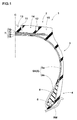
- FIG. 1 is a cross-sectional view on the tire meridian section including the tire axis at standard state of a heavy duty tire 1 of the present invention.
- the "standard state” means a sate of a tire filled with standard internal pressure with no-load is assembled on a standard rim (not shown).
- dimensions and the like of each part of the tire are values measured in the standard state.
- the "normal rim” is a rim determined for each tire by a standard including one on which the tire is based. For example, it is a standard rim in the case of JATMA, a "Design Rim” in the case of TRA, and a “Measuring Rim” in the case of ETRTO.
- the "normal internal pressure” means an air pressure determined for each tire by the standard. For example, it is the maximum air pressure in JATMA, the maximum value described in a table "TIRE LOAD LIMITS AT VARIOUS COLD INFLATION PRESSURES" in the case of TRA, and the "INFLATION PRESSURE" in the case of ETRTO.
- the heavy duty tire 1 of the present invention comprises a toroidal carcass 6 extending from a tread portion 2 through a sidewall portion 3 to a bead core 5 of a bead portion 4, and a belt layer 7 or the like disposed radially outward of the carcass 6 and inward of the tread portion 2.
- This embodiment shows a case that the heavy duty tire 1 is a tubeless tire mounted on a 15 degrees taper rim RM.
- the carcass 6 is composed of a carcass ply 6A having an array of carcass cord at an angle of from 80 to 90 degrees, for example, with respect to the tire equator C.
- the carcass ply 6A is provided on both ends of the ply main portion 6a between the bead cores 5 and 5 with a ply turnup portion 6b turned up from inside to outside in the tire axial direction around each of the bead cores 5.
- a bead apex rubber 8 having a triangular cross-section extending radially outward from the bead core 5.
- the belt layer 7 is disposed radially outside of the carcass 6 and inside the tread portion 2.
- the belt layer 7 is formed of a plurality of belt plies with the use of a steel belt cord.
- the belt layer 7 of the present embodiment has four layers: an innermost belt ply 7A, and belt plies 7B, 7C and 7D successively disposed outside of the belt ply 7A.
- a belt cord is arranged at an angle of about from 60 ⁇ 10 degrees, for example, with respect to the tire equator C.
- belt plies 7B, 7C and 7D belt cords are arranged at a small angle of about from 15 to 35 degrees with respect to the tire equator C.
- the belt layers 7 comprises at least one cross over point where the belt cords intersect each other between the plies, thereby increasing the belt rigidity and firmly reinforcing an approximately entire width of the tread portion 2.
- the bead core 5 has a flat oblong hexagonal in cross-section, and the radially inner surface is inclined at an angle of from 12 to 18 degrees with respect to the tire axial direction, therefore a fitting force with the rim RM is widely increased.
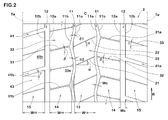
- FIG. 2 is a development view of the tread portion 2 of the heavy duty tire 1 of the present embodiment. As shown in FIG. 2 , the heavy duty tire 1 of the present embodiment is provided in the tread portion 2 with a directional pattern where a rotational direction R of the tire is specified.
- the tread portion 2 comprises a pair of center main grooves 11 disposed on both sides of the tire equator C and a pair of shoulder main grooves 12.
- the center main grooves 11 extend continuously in a zigzag shape in the ti re circumferential direction.
- the shoulder main grooves 12 extends continuously linearly in the tire circumferential direction on an axially outside of the center main groove 11 and on an axially inside of the tread ground contact edge Te.
- the tread ground contact edge Te means the axially outmost ground end of the tire under the normal state and the normal load at a camber angle of 0 degrees plane.
- the "normal load” is a load determined for each tire by the standard. For example, it is the maximum load ability in the case of JATMA, the maximum value described in a Table "TIRE LOAD LIMITS AT VARIOUS COLD INFLATION PRESSURES" in the case of TRA, and the "LOAD CAPACITY" in the case of ETRTO.
- the center main groove 11 having the zigzag shape secures an axial edge component of the center main groove 11 and improves the rolling resistance performance. Furthermore, in the heavy duty tire 1 the drainage performance of the tread portion 2 is enhanced by the linear shoulder main grooves 12, thereby improving the wet performance.
- Angles ⁇ 1 and ⁇ 2 of zigzags to the tire circumferential direction of the center main groove 11 are, for example, preferably not less than 10 degrees and preferably not more than 15 degrees, and more preferably not more than 12.5 degrees. If the angles ⁇ 1 and ⁇ 2 are less than 10 degrees, the tire axial edge component of the center main groove 11 runs out, and brake performance and traction performance on a wet road surface may be reduced. On the other hand, the angles ⁇ 1 and ⁇ 2 exceed 15 degrees, the drainage performance of the center main groove 11 may decrease.
- the center main groove 11 on a first side of the tire equator C is arranged in circumferentially shifting of zigzag phase with the center main groove 11 on a second side of the tire equator C.
- the center main groove 11 comprises a first groove edge 11a on a side of the tire equator C, i.e. on an axially inner side, and a second groove edge 11b on a side of the tread ground contact edge Te, i.e. on an axially outer side.
- the shoulder main groove 12 comprises a third groove edge 12a on the side of the tire equator C and a fourth groove edge 12b on the side of the tread ground contact edge Te.
- FIG. 3 is an enlarged view of a vicinity of tire equator C of the tread portion 2 including the pair of center main grooves 11.
- the first groove edge 11a of the center main groove 11 comprises an inner top portion 11c protruding axially most inward and an outer top portion 11d protruding axially most outward.
- the inner top portion 11c of the present embodiment is formed of a longitudinal edge 11e extending in the tire circumferential direction.
- the outer top portion 11d is formed of a longitudinal edge 11f extending in the tire circumferential direction. That is, the inner top portion 11c and the outer top portion 11d are formed of a region being continuous in the ti re circumferential direction of the first groove edges 11a.
- the longitudinal edge 11e and the longitudinal edge 11f may be omitted. In this case, a zigzag vertex of the first groove edge 11a is the inner top portion 11c or the outer top portion 11d.
- the second groove edge 11b of the center main groove 11 comprises an inner top portion 11g protruding axially most inward and an outer top portion 11h protruding axially most outward.
- the inner top portion 11g of the present embodiment is formed of a longitudinal edge 11i extending in the ti re circumferential direction. That is, the inner top portion 11g is formed of a region being continuous in the ti re ci rcumferenti al di rection of the second groove edges 11b.
- the longitudinal edge 11i may be omitted. In this case, a zigzag vertex protruding toward the tire equator C of the first groove edge 11b is the inner top portion 11g. Owi ng to the longitudinal edges 11e, 11f and 11i, water is easily discharged in the circumferential direction of the ti re, and the drainage performance of the tread portion 2 is increased.
- the groove width Ws of the shoulder main grooves 12 is preferably larger than the groove width Wc of the center main groove 11. If the groove wi dth Wc of the center main groove 11 is larger than the groove width Ws of the shoulder main grooves 12, the rigidity of the tread portion 2 i s insufficient i n the vi ci ni ty of the ti re equator C having a hi gh ground pressure; therefore rolling resistance performance is likely to be worse.
- a ratio Ws/Wc between the groove width Ws of the shoulder main grooves 12 and the groove width Wc of the center main groove 11 is, for example, preferably from 1.5 to 2.0. If the ratio Ws/Wc is less than 1.5, the drainage performance in a peripheral portion of the shoulder main groove 12 may be decreased. On the other hand, if the ratio Ws/Wc exceeds 2.0, the rigidity of the peripheral portion of the shoulder main groove 12 is decreased, and the deformation of the tread portion 2 is increased, therefore the rolling resistance performance may be deteriorated.
- a groove depth of the shoulder main groove 12 is equal to a groove depth of the center main groove 11, for example.
- the tread portion 2 is divided into a plurality of land regions by the pair of center main grooves 11 and the pair of shoulder main grooves 12. More specifically, the tread portion 2 is divided into regions: a center land portion 13, a pair of middle land portions 14, and a pair of shoulder land portion 15.
- the center land portion 13 is disposed between the center main groove 11 on the first side and the center main groove 11 on the second side of the tire equator C.
- the middle land portion 14 is disposed between the center main groove 11 and the shoulder main groove 12.
- the shoulder land portion 15 is disposed on an axial outside of the shoulder main groove 12. That is, on both sides of the center main groove 11, the center land portion 13 and the middle land portion 14 are provided. On both sides of the shoulder main groove 12, the middle land portion 14 and the shoulder land portion 15 are provided.
- a ratio W13 : W14 : W15 of an axial average width W13 of the center land portion 13, an axial average width W14 of the middle land portion 14, and an axial width W15 of the shoulder land portion 15 is preferably 1.00 : from 1.00 to 1.08 : from 1.03 to 1.13, for example. If a ratio W14/W13 is less than 1.00 and if a ratio W15/W13 is less than 1.08, the ground contact pressure of the center land portion 13 is excessively hi gh, and the re is a possibility that uneven wear is generated in the center land portion 13. On the other hand, the ratio W14/W13 exceeds 1.03 and if the ratio W15/W13 exceeds 1.13, the ground contact pressures of the middle land portion 14 and the shoulder land portion 15 are excessively high, therefore it is difficult to reduce in rolling resistance.
- the center land portion 13 comprises a plurality of fi rst center inclined si pes 21 and a plurality of second center inclined sipes 22.
- Each of the first center inclined sipes 21 and the second center inclined sipes 22 extends at an angle with respect to the tire axial direction, and communicates between the center main groove 11 on the first side of the tire equator C and the center main groove 11 on the second side of the tire equator C.
- the center land portion 13 does not comprise any lateral grooves nor inclined grooves communicating between the center main groove 11 on the first side of the tire equator C and the center main groove 11 on the second side of the tire equator C.
- This center land portion 13 has a high rigidity in the tire circumferential direction, which contributes to improvement in rolling resistance performance.
- Each of the fi rst center inclined si pes 21 communi cates between the inner top portion 11c of the first groove edge 11a on the first si de and the inner top portion 11c of the first groove edge 11a on the second side of the tire equator C.
- the center land portion 13, whi ch i s divi ded by the pair of the center main grooves 11 arranged in circumferentially shifting of zigzag phase and the first center inclined sipes 21, has a substantially hexagonal barrel-shape.
- the rigidity of near-field region of its outer top portion 11d is high, and the deformation of this region at the time of grounding is suppressed.
- the center land portion 13 is a block row in which a plurality of center blocks 23 divided by the first center inclined si pes 21 and the second center inclined sipes 22 are arranged.
- a ratio Le/Pc between a tire circumferential length Le of the longitudinal edge 11e and a distance Pc between the circumferentially adjacent first center inclined si pes 21 and 21 is preferably from 0.1 to 0.4, for example. If the ratio Le/Pc is less than 0.1, the rigidity of the inner top portion 11c of the center block 23 is locally lowered, and the inner top portion 11c tends to be a starting point of uneven wear. If the ratio Le/Pc exceeds 0.4, the overall rigidity of the center block 23 is lowered, and it is difficult to reduce the rolling resistance of the tire.
- a ratio Lf/Pc between a tire circumferential length Lf of the longitudinal edge 11f and a distance Pc between the circumferentially adjacent fi rst center inclined si pes 21 and 21 is also preferably from 0.1 to 0.4, for example.
- a ratio Wcs1/Pc between a wi dth Wcs1 of the fi rst center inclined si pe 21 and the di stance Pc between the fi rst center inclined sipes 21 and 21 adjacent in the tire circumferential direction is preferably not more than 0.02, more preferably not more than 0.01, for example. If the ratio Wcs1/Pc exceeds 0.02, an area where side walls of the adjacent center blocks 23 abut decreases; therefore, it is difficult to obtain an effect in rigidity improvement by supporting the adjacent center blocks 23, that is the side walls of the sipes, each other.
- a width Wcs2 of the second center inclined sipe 22 is equivalent to the width Wcs1 of the first center inclined sipe 21.
- the second center inclined sipe 22 is parallel to the first center inclined sipe 21. Owing to this second center inclined sipe 22, a rigidity distribution of the center block 23 is optimized, and the wet performance of the center land portion 13 is increased.
- the center main groove 11 on the first side of the tire equator C is arranged in shifting of zigzag phase wi th respect to the center main groove 11 on the second side of the ti re equator C in a circumferential di rection. Therefore, the fi rst center inclined si pe 21 and the second center inclined si pe 22 are inclined with respect to the tire axial direction, and the drainage performance of the center land portion 13 is increased.
- Each of depths of the first center inclined si pe 21 and the second center inclined sipe 22 is preferably from 50% to 80% of a depth of the center main groove 11, more preferably from 65% to 75%, for example. If the depth of the first center inclined sipe 21 and the like is less than 50% of the depth of the center main groove 11, the high rigidity by the block can be obtained, however, the area where the sidewalls of the adjacent blocks abut decreases; therefore, it is difficult to obtain the effect in rigidity improvement by supporting the adjacent blocks each other. Thus the rigidity of the entire center land portion 13 decreases and it is difficult to reduce the rolling resistance of the tire. On the other hand, if the depth of the fi rst center inclined si pe 21 and the like exceeds 80% of the depth of the center main groove 11, the rigidity by the block significantly decreases, and it is difficult to reduce the rolling resistance of the tire.
- a sharp vertex is formed of a chamfered portion 24.
- the chamfer 24 relieves stress concentration at the block vertex and suppresses damage such as chipping.
- a corner rounded portion may be formed.
- FIG. 4 is an enlarged view of the center main groove 11, the middle land portion 14 and the shoulder main groove 12.
- the middle land portion 14 comprises a plurality of middle inclined grooves 31 and a plurality of middle inclined sipes 32.
- Each of the middle inclined grooves 31 and the middle inclined sipes 32 extends at an angle in the tire axial direction and communicates the center main groove 11 and the shoulder main groove 12.
- the middle inclined groove 31 In the middle inclined groove 31, one end thereof communicates with the outside top portion 11h of the second groove edge 11b of the center main groove 11, and the other end thereof communicates with the third groove edge 12a of the shoulder main grooves 12, respectively.
- the middle land portion 14 is a block row in which a plurality of middle blocks 33 are arranged. Owing to the zigzag center main groove 11, the linear shoulder main groove 12 and the adjacent middle inclined grooves 31 and 31, the tread surface 33s of the middle block 33 of this embodiment has a substantially pentagon.
- each of the middle inclined grooves 31a on the fi rst side of the ti re equator C is inclined in the opposi te direction to the middle inclined groove 31b on the second side with respect to the tire axial direction.
- the tread portion 2 comprises a directional pattern having a specified rotational direction R. This directional pattern enhances the drainage performance of the tread portion 2 and improves the wet performance of the heavy duty tire 1.
- a ratio Li/Pm between a tire circumferential length Li of the longitudinal edge 11i and a distance Pm between the circumferentially adjacent middle inclined grooves 31 and 31 is preferably from 0.1 to 0.4, for example. If the above ratio Li/Pm is less than 0.1, the rigidity of the inner top portion 11g of the middle blocks 33 locally decreases, and the inner top portion 11g likely to be the starting point of the uneven wear. If the ratio Li/Pm exceeds 0.4, it reduces the overall rigidity of the middle block 33 and the reduction in rolling resistance of the tire is difficult.
- Each of the middle inclined sipes 32 communicates between the inner top portion 11g of the second groove edge 11b of the center main groove 11 and the thi rd groove edge 12a of the shoulder main grooves 12.
- the middle inclined sipe 32 is arranged parallel to the middle inclined groove 31 and divides the tread surface 33s of the middle block 33 into two. Owing to this middle inclined sipe 32, the rigidity distribution of the middle block 33 is optimized, and the wet performance of the middle land portion 14 is improved. Furthermore, the middle inclined sipe 32 closes at the time of grounding, and the adjacent sipe side walls attach fi rmly and support each other, thereby increasing the rigidity of the middle land portion 14. Accordingly, the deformation of the middle land portion 14 is suppressed, and the rolling resistance performance is improved.
- the first center inclined sipe 21 is formed so as to communicate wi th the middle inclined si pe 32 through the center main groove 11.
- the above-mentioned expression that the first center inclined sipe 21 communicates with the middle inclined sipe 32 through the center main groove 11 means that an extended line of the first center inclined sipe 21 and an extended line of the mi ddl e inclined si pe 32 intersect one another in the center main groove 11. This arrangement of the first center inclined sipe 21 and the middle inclined sipe 32 improves the wet performance.
- a ratio Wms/Pm between a width Wms of the middle inclined sipe 32 and a distance Pm between the circumferentially adjacent middle inclined grooves 31 and 31 is preferably not more than 0.02, more preferably not more than 0.01, for example. If the ratio Wms/Pm exceeds 0.02, since the area where the adjacent si pe si de walls abut each other decreases, it is difficult to obtain the effect in increase of the rigidity of supporting the middle blocks 33 each other.
- the depth of the middle inclined groove 31 is preferably from 10% to 30% of the depth of the center main groove 11, for example. If the depth of the middle inclined groove 31 is less than 10% of the depth of the center main groove 11, there is a possibility that the drainage performance of the middle land portion 14 is reduced. On the other hand, if the depth of the mi ddl e inclined groove 31 exceeds 30% of the depth of the center main groove 11, the rigidity of the middle land portion 14 is decreased, and the rolling resistance performance may be deteriorated.
- the middle land portion 14 is provided on both ends of the middle inclined sipe 32 with a pair of first chamfered portions 36 and a pair of second chamfered portions 37.
- Each of fi rst chamfered portions 36 is disposed on a first corner portion 36c sandwiched between the middle inclined sipe 32 and the center main groove 11.
- the first chamfered portion 36 is lowered from the tread surface 33s of the middle block 33 toward a groove bottom of the center main groove 11.
- each of the second chamfered portions 37 is disposed in a second corner portion 37c sandwiched between the middle inclined sipes 32 and the shoulder main groove 12.
- the second chamfered portion 37 is lowered from the tread surface 33s of the middle block 33 to the groove bottom of the shoulder main grooves 12.
- the fi rst chamfered portion 36 and the second chamfered portion 37 alleviates the stress concentration at the apex of the first corner portion 36c and the second corner portion 37c, and the damage such as chipping is suppressed.
- corner rounding portions may be formed.
- the middle land portion 14 is provided on both ends of the middle inclined groove 31 with a third chamfered portion 38 and a fourth chamfered portion 39.
- the third chamfered portion 38 is disposed on an acute-angled third corner portion 38c sandwiched between the middle inclined groove 31 and the center main groove 11.
- the third chamfered portion 38 is lowered from the tread surface 33s of the middle block 33 toward the groove bottom of the center main groove 11.
- the fourth chamfered portion 39 is disposed on an acute-angled fourth corner portion 39c sandwiched between the middle inclined grooves 31 and the shoulder main groove 12.
- the fourth chamfered portion 39 is lowered from the tread surface 33s of the middle block 33 toward the groove bottom of the shoulder main groove 12.
- third chamfered portion 38 and fourth chamfered portion 39 alleviate the stress concentration at the vertices of the third corner portion 38c and the fourth corner portion 39c and suppress the damage such as chipping.
- corner rounding portions may be formed.
- Each angle ⁇ of the middle inclined groove 31 and the middle inclined sipe 32 with respect to the tire axial direction is preferably from 5 to 20 degrees, for example. If the angle ⁇ is less than 5 degrees, there is a possibility that the drainage performance of the middle land portion 14 is decreased. On the other hand, if the angle ⁇ exceeds 20 degrees, there is a possibility that the rigidity of the middle land portion 14 is decreased and that the rolling resistance is increased.
- the angle of the middle inclined groove 31 with respect to the tire axial direction and the angle of the middle inclined sipe 32 with respect to the tire axial direction may be different one another if within the above-mentioned ranges.
- the number of each the middle inclined grooves 31 and the middle inclined sipe 32 provided in a single middle land portion 14 is preferably from 35 to 45, more preferably from 38 to 42, for example. If the number is less than 35, there is a possibility that the drainage performance of the middle land portion 14 is decreased. On the other hand, if the above-mentioned number exceeds 45, the rigidity of the middle land portion 14 is decreased and the reduction in rolling resistance of the tire is difficult.
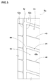
- FIG. 5 is an enlarged view of the shoulder main groove 12 and the shoulder land portion 15.
- the shoulder land portion 15 comprises a plurality of shoulder inclined grooves 41 and a plurality of shoulder inclined sipes 42.
- Each of the shoulder inclined grooves 41 and the shoulder inclined si pes 42 extends at an angle in the ti re axial direction and communicates with the shoulder main groove 12 and the tread ground end Te.
- the shoulder land portion 15 is a block row in which a plurality of shoulder blocks 43 are arranged. Owing to the linear shoulder main grooves 12 and the adjacent shoulder inclined grooves 41, a tread surface 43s of the shoulder block 43 of the present embodiment has a substantially parallelogram.
- a depth of the shoulder inclined groove 41 is preferably from 10% to 30% of the depth of the shoulder main groove 12, for example. If the depth of the shoulder inclined groove 41 is less than 10% of the depth of the shoulder main groove 12, there is a possibility that the drainage performance of the shoulder land portion 15 decreases. On the other hand, if the depth of the shoulder inclined groove 41 exceeds 30% of the depth of the shoulder main groove 12, the ri gi di ty of the shoulder land portion 15 is decreased, and the rolling resistance performance may be decreased.
- each of the shoulder inclined grooves 41a on the first side of the tire equator C is inclined in the same direction with respect to the tire axial direction as the adjacent middle inclined groove 31a across the shoulder main groove 12.
- the shoulder inclined groove 41b on the second side of the tire equator C is also inclined in the same direction with respect to the tire axial direction as the adjacent middle inclined groove 31b across the shoulder main groove 12.
- the shoulder inclined groove 41a on the first side is inclined in the opposite direction with respect to the axial direction to the shoulder inclined groove 41b on the second si de.
- the tread portion 2 comprises the directional pattern has the specified rotational direction R. This directional pattern enhances the drainage performance of the tread portion 2 and improves the wet performance of the heavy duty tire 1.
- the shoulder inclined sipe 42 As shown in FIG. 5 , in the shoulder inclined sipe 42, one end thereof communicates with the fourth groove edge 12b of the shoulder main groove 12, and the other end thereof communicates with the tread ground contact edge Te.
- the shoulder inclined sipe 42 is provided parallel to the shoulder inclined groove 41, thereby dividing the tread surface 43s of the shoulder block 43 in two. Owing to this shoulder inclined sipe 42, the rigidity distribution of the shoulder blocks 43 is optimized, and the wet performance of the shoulder land portion 15 is increased. Furthermore, the shoulder inclined sipe 42 closes at the time of grounding, and the adjacent sipe side walls attach firmly and support each other, thereby improving the rigidity of the shoulder land portion 15. Accordingly, the deformation of the shoulder land portion 15 is suppressed, and the rolling resistance performance is improved.
- a depth of the shoulder inclined sipe 42 is preferably from 50% to 80% of the depth of the center main groove 11, for example. If the depth of the shoulder inclined sipe 42 is less than 50% of the depth of the center main groove 11, the high rigidity by the block can be obtained. However, the area where the side walls of the adjacent sipes abut decreases, it is therefore difficult to obtain the effect in rigidity improvement of supporting the blocks each other. Therefore, the rigidity of the entire shoulder land portion 15 is decreased, and it is difficult to reduce the rolling resistance of the tire. On the other hand, if the depth of the shoulder inclined sipe 42 exceeds 80% of the depth of the center main groove 11, the rigidity by the block significantly decreases, and it is difficult to reduce the rolling resistance of the tire.
- a sharp vertex comprises a chamfered portion 44.
- the chamfered portion44 alleviates the stress concentration at the block vertices and suppresses the damage such as chipping. Instead of the chamfered portion 44, a corner rounded portion may be formed.
- the number of each of the shoulder inclined grooves 41 and the shoulder inclined sipes 42 provided in a single shoulder land portion 15 is the same as the number of each of the middle inclined grooves 31 and the middle inclined sipes 32 provided in a single middle land portion 14.
- each angle ⁇ of the first center inclined sipe 21 and the second center inclined sipe 22 with respect to the tire axial direction is preferably larger than each angle ⁇ of the shoulder inclined groove 41 and the shoulder inclined sipe 42 with respect to the tire axial direction. Owing to these first center inclined sipe 21 and second center inclined sipe 22, the rigidity of the center land portion 13 in the tire circumferential direction is secured, and the reduction of rolling resistance performance is suppressed.
- the angle ⁇ is preferably larger than the angle ⁇ of each of the middle inclined groove 31 and the middle inclined sipe 32 with respect to the tire axial direction. Owing to these shoulder inclined groove 41 and shoulder inclined si pe 42, the drainage performance of the shoulder land portion 15 is increased, and the wet performance is improved.
- a land ratio of the tread portion 2 comprising the above-described pattern is preferably not less than 80%, for example. If the land ratio is less than 80%, due to lack of rubber volume of the tread portion 2, the rigidity of the tread portion 2 decreases, and the rolling resistance performance is deteriorated.
- FIG. 6 shows a grounding shape of the heavy duty tire 1.
- a ratio Ls/Lc between a ground contact length Ls of the fourth groove edge 12b of the shoulder main groove 12 of the shoulder land portion 15 and a ground contact length Lc of the center land portion 13 in the tire equator C is preferably from 0.9 to 1.0, for example. If the ratio Ls/Lc is less than 0.9, the ground contact pressure of the shoulder land portion 15 is lowered, and uneven wear referred to as shoulder wear occurs. If the ratio Ls/Lc exceeds 1.0, the local slippage occurs in the middle land portion 14 or the like at the time of grounding, and there is a possibility that uneven wear occurs.
- the shoulder main groove 12 is formed linearly in the tire circumferential direction, and the groove width Ws of the shoulder main groove 12 is larger than the groove width Wc of the center main groove 11.
- the drainage performance of the tread portion 2 is enhanced thereby improving the wet performance.
- the middle inclined groove 31 and the shoulder inclined groove 41, whi ch are inclined wi th respect to the ti re axial direction, are disposed in the middle land portion 14 and the shoulder land portion 15, the drainage from the middle land portion 14 to the tread ground contact edge Te is promoted, thereby improving the wet performance more.
- the first center inclined sipe 21 and the second center inclined sipe 22 provided in the center land portion 13 are closed at the time of grounding, therefore the adjacent sipe side walls attach firmly and support each other, thereby increasing the rigidity of the tread portion 2. Accordingly, the deformation of the center land portion 13 having high ground pressure is suppressed, and the rolling resistance performance is improved.
- the heavy duty tire of the present invention has been described in detail, but the present invention is implemented by changi ng the vari ous aspects wi thout bei ng limited to the speci fi c embodiments described above.
- Heavy duty ti res each having a size of 315/80R22.5 and comprising a tread pattern shown in FIG. 2 were formed based on the specifications shown in Table 1.
- Each of the tires was mounted on a rim of 22.5 x 9.00 and tested in rolling resistance performance and wet braking performance.
- Each of groove depths of the center main groove and the shoulder main groove of the test tire was 16.3 mm. Test methods are as follows.
- each of the test tires was tested in the rolling resistance under the conditions of an internal pressure of 850 kPa, a load of 33.34 kN and a speed of 80 km/h.
- the result is an index obtained by Example 1 as 100. Higher the numerical value, the smaller the rolling resistance, thereby excelling in fuel economy performance.
- Example 1 Under the conditions of an inner pressure of 595 kPa, a load of 27.63 kN and a speed of 50 km/h, a braking force was applied to a shaft of each of the test tires, and a peak value of a friction coefficient was measured. The result is an index to the value of Example 1 as 100. Higher the numerical value, the better the wet braking performance.
- test tires were mounted on the all wheels of a track (2-D vehicle) of the maximum load of 10 ton.
- the vehicle ran 10000 km in a state of constant load, respective block rows of a center land portion, a middle land portions and a shoulder land portion were observed with naked eyes in presence of uneven wear.
- the result is an index to the val ue of Example 1 as 100. Higher the numerical val ue, the better the uneven wear resistance.
Landscapes
- Engineering & Computer Science (AREA)
- Mechanical Engineering (AREA)
- Tires In General (AREA)
Abstract
Description
- The present invention relates to a heavy duty tire sati sfyi ng both of rolling resistance performance and wet performance at a high level.
- In the heavy duty tire which is used like a truck and a bus, the high wet performance is requi red. For example, the following
Patent Document 1 proposes a ti re is provided in a center land portion, a middle land portion and a shoulder land portion of a tread portion are provided with a number of lateral grooves, thereby increasing a groove volume and enhancing the wet performance. - Patent Document 1: Japanese published unexamined application No.
H11-034614 - However, in the heavy duty tire disclosed in the above-mentioned
Patent Document 1, with the increase of the groove volume, the rigidity of the tread portion decreases, and the rolling resistance and abrasion resistance performance are deteriorated. For increasing the wear resistance performance, a method to increase the rubber volume of the tread portion is valid, but the increase in the rubber volume leads to further deterioration of the rolling resistance performance. - The present invention has been therefore devi sed i n vi ew of the circumstances described above, and has amain purpose to provide a heavy duty tire satisfying both of the rolling resistance performance and the wet performance at a high level.
- The present invention relates to a heavy duty tire comprising, in a tread portion, a pair of center main grooves disposed on both outer sides of the tire equator and extending continuously in a zigzag shape in the tire circumferential direction, and a pair of the shoulder main grooves disposed on the axially outer sides of the center main groove and extending continuously linearly in the tire circumferential direction, and thereby dividing the tread portion into a center land portion between the pair of center main grooves, a pair of middle land portion each disposed between the center main groove and the shoulder main groove, and a pair of shoulder land portion each disposed axially outside of the respective shoulder main groove. A groove width Ws of each of the shoulder main grooves is larger than the groove width Wc of each of the center main grooves. Each of the middle land portions is provided wi th a plurality of mi ddl e inclined grooves extending at an angle wi th respect to the ti re axial direction and each communicating between an axially outer top portion of the center main groove and the shoulder main groove. Each of the shoulder land portions is provided with a plurality of shoulder inclined grooves extending at an angle wi th respect to the tire axial direction and each communicating between the shoulder main groove and the tread grounding end. A groove width of the shoulder inclined groove is larger than a groove width of the middle inclined groove. The center land portion comprises a first center inclined sipe extending at an angle with respect to the tire axial direction and communicating between axially inner top portions of the center main groove to each other, and a second center inclined sipe extending at the same direction as the first center inclined sipe and communicating between axially outer top portions of the center main groove to each other.
- In the heavy duty ti re accordi ng to the present invention, the middle inclined groove on a first side of the tire equator is inclined in the opposite direction to the middle inclined groove of a second side of the tire equator.
- In the heavy duty ti re accordi ng to the present invention, the shoulder inclined groove on the first side of the tire equator is inclined in the opposi te di recti on to the shoulder inclined groove of the second side of the tire equator.
- In the heavy duty ti re accordi ng to the present invention, each angle of the first center inclined sipe and the second center inclined sipe with respect to the ti re axial di recti on is larger than angles of the middle inclined groove and the shoulder inclined groove with respect to the tire axial direction.
- In the heavy duty ti re accordi ng to the present i nventi on, between the circumferentially adjacent middle inclined grooves, a middle inclined sipe extending parallel to the middle inclined grooves is formed, and between the circumferentially adjacent shoulder inclined grooves, a shoulder inclined sipe extending parallel to the shoulder inclined grooves is formed.
- In the heavy-duty tire according to the present invention, the middle inclined sipes is communicated between the center main groove and the shoulder main groove, the middle land portion is provided on a first corner portion sandwiched between the middle inclined si pe and the center main groove wi th a first chamfered portion descending toward the center main groove, and is provided on a second corner portion sandwiched between the middle inclined sipe and the shoulder main groove with a second chamfered portion descending toward the shoulder main groove.
- In the heavy duty tire accordi ng to the present invention, the first center inclined sipe is formed to be continuous with the middle inclined sipe via the center main groove.
- In the heavy duty ti re accordi ng to the present invention, a land ratio of the tread portion is not less than 80%.
- In the heavy duty ti re accordi ng to the present invention, a ratio Ws/Wc between the groove width Ws of the shoulder main groove and the groove wi dth Wc of the center main groove is from 1.5 to 2.0.
- In the heavy duty ti re accordi ng to the present invention, the center main groove has an angle of from 10 to 15 degrees with respect to the tire circumferential direction.
- In the heavy-duty tire according to the present invention, a ratio Ls/Lc between a ground contact length Ls of a groove edge of the shoulder main groove of the shoulder land portion and a ground contact length Lc in the tire equator is from 0.9 to 1.0.
- In the heavy duty tire of the present invention, the shoulder main groove is formed linearly in the tire circumferential direction, and the groove width Ws of the shoulder main groove is larger than the groove width Wc of the center main groove. This shoulder main groove enhances drainage performance of the tread portion, thereby improving the wet performance. Further, since the middle land portion and the shoulder land portion are provided with the middle inclined groove and the shoulder inclined groove inclined wi th respect to the ti re axial direction, the drainage from the mi ddl e land portion to the tread grounding end is promoted, and the wet performance is more improved.
- On the other hand, since the fi rst center inclined si pe and the second center inclined si pe provided in the center land portion are closed at a time of grounding, the adjacent sipe side walls attach firmly and support each other, thereby improving the rigidity of the tread portion. Accordingly, deformation of the center land portion having high ground pressure is suppressed, thereby improving rolling resistance performance.
-
-
FIG. 1 is a cross-sectional view showing an embodiment of a heavy duty tire of the present invention. -
FIG. 2 is a development view of a tread portion shown inFIG. 1 . -
FIG. 3 is an enlarged development view of a crown land portion shown inFIG. 2 . -
FIG. 4 is an enlarged development view of a middle land portion shown inFIG. 2 . -
FIG. 5 is an enlarged development view of a shoulder land portion shown inFIG. 2 . -
FIG. 6 is a drawing showing a ground contacting shape of the heavy duty tire ofFIG. 1 . - Hereinafter, an embodiment of the present invention will be described with reference to the accompanying drawings.
-
FIG. 1 is a cross-sectional view on the tire meridian section including the tire axis at standard state of aheavy duty tire 1 of the present invention. Here, the "standard state" means a sate of a tire filled with standard internal pressure with no-load is assembled on a standard rim (not shown). Hereinafter, if not specifically mentioned, dimensions and the like of each part of the tire are values measured in the standard state. - The "normal rim" is a rim determined for each tire by a standard including one on which the tire is based. For example, it is a standard rim in the case of JATMA, a "Design Rim" in the case of TRA, and a "Measuring Rim" in the case of ETRTO.
- The "normal internal pressure" means an air pressure determined for each tire by the standard. For example, it is the maximum air pressure in JATMA, the maximum value described in a table "TIRE LOAD LIMITS AT VARIOUS COLD INFLATION PRESSURES" in the case of TRA, and the "INFLATION PRESSURE" in the case of ETRTO.
- As shown in
FIG. 1 , theheavy duty tire 1 of the present invention comprises atoroidal carcass 6 extending from atread portion 2 through asidewall portion 3 to abead core 5 of abead portion 4, and abelt layer 7 or the like disposed radially outward of thecarcass 6 and inward of thetread portion 2. This embodiment shows a case that theheavy duty tire 1 is a tubeless tire mounted on a 15 degrees taper rim RM. - The
carcass 6 is composed of acarcass ply 6A having an array of carcass cord at an angle of from 80 to 90 degrees, for example, with respect to the tire equator C. Thecarcass ply 6A is provided on both ends of the plymain portion 6a between thebead cores ply turnup portion 6b turned up from inside to outside in the tire axial direction around each of thebead cores 5. Between the plymain portion 6a and theply turnup portion 6b, there is abead apex rubber 8 having a triangular cross-section extending radially outward from thebead core 5. - The
belt layer 7 is disposed radially outside of thecarcass 6 and inside thetread portion 2. Thebelt layer 7 is formed of a plurality of belt plies with the use of a steel belt cord. Thebelt layer 7 of the present embodiment has four layers: aninnermost belt ply 7A, and belt plies 7B, 7C and 7D successively disposed outside of thebelt ply 7A. In theinner belt ply 7A, a belt cord is arranged at an angle of about from 60 ± 10 degrees, for example, with respect to the tire equator C. In the belt plies 7B, 7C and 7D, belt cords are arranged at a small angle of about from 15 to 35 degrees with respect to the tire equator C. The belt layers 7 comprises at least one cross over point where the belt cords intersect each other between the plies, thereby increasing the belt rigidity and firmly reinforcing an approximately entire width of thetread portion 2. - The
bead core 5 has a flat oblong hexagonal in cross-section, and the radially inner surface is inclined at an angle of from 12 to 18 degrees with respect to the tire axial direction, therefore a fitting force with the rim RM is widely increased. -
FIG. 2 is a development view of thetread portion 2 of theheavy duty tire 1 of the present embodiment. As shown inFIG. 2 , theheavy duty tire 1 of the present embodiment is provided in thetread portion 2 with a directional pattern where a rotational direction R of the tire is specified. - The
tread portion 2 comprises a pair of centermain grooves 11 disposed on both sides of the tire equator C and a pair of shouldermain grooves 12. The centermain grooves 11 extend continuously in a zigzag shape in the ti re circumferential direction. The shouldermain grooves 12 extends continuously linearly in the tire circumferential direction on an axially outside of the centermain groove 11 and on an axially inside of the tread ground contact edge Te. - The tread ground contact edge Te means the axially outmost ground end of the tire under the normal state and the normal load at a camber angle of 0 degrees plane. The "normal load" is a load determined for each tire by the standard. For example, it is the maximum load ability in the case of JATMA, the maximum value described in a Table "TIRE LOAD LIMITS AT VARIOUS COLD INFLATION PRESSURES" in the case of TRA, and the "LOAD CAPACITY" in the case of ETRTO.
- In the
heavy duty tire 1 of the present embodiment, the centermain groove 11 having the zigzag shape secures an axial edge component of the centermain groove 11 and improves the rolling resistance performance. Furthermore, in theheavy duty tire 1 the drainage performance of thetread portion 2 is enhanced by the linear shouldermain grooves 12, thereby improving the wet performance. - Angles θ1 and θ2 of zigzags to the tire circumferential direction of the center
main groove 11 are, for example, preferably not less than 10 degrees and preferably not more than 15 degrees, and more preferably not more than 12.5 degrees. If the angles θ1 and θ2 are less than 10 degrees, the tire axial edge component of the centermain groove 11 runs out, and brake performance and traction performance on a wet road surface may be reduced. On the other hand, the angles θ1 and θ2 exceed 15 degrees, the drainage performance of the centermain groove 11 may decrease. - The center
main groove 11 on a first side of the tire equator C is arranged in circumferentially shifting of zigzag phase with the centermain groove 11 on a second side of the tire equator C. - The center
main groove 11 comprises afirst groove edge 11a on a side of the tire equator C, i.e. on an axially inner side, and asecond groove edge 11b on a side of the tread ground contact edge Te, i.e. on an axially outer side. The shouldermain groove 12 comprises athird groove edge 12a on the side of the tire equator C and afourth groove edge 12b on the side of the tread ground contact edge Te. -
FIG. 3 is an enlarged view of a vicinity of tire equator C of thetread portion 2 including the pair of centermain grooves 11. Thefirst groove edge 11a of the centermain groove 11 comprises an innertop portion 11c protruding axially most inward and an outertop portion 11d protruding axially most outward. The innertop portion 11c of the present embodiment is formed of alongitudinal edge 11e extending in the tire circumferential direction. The outertop portion 11d is formed of alongitudinal edge 11f extending in the tire circumferential direction. That is, the innertop portion 11c and the outertop portion 11d are formed of a region being continuous in the ti re circumferential direction of thefirst groove edges 11a. Thelongitudinal edge 11e and thelongitudinal edge 11f may be omitted. In this case, a zigzag vertex of thefirst groove edge 11a is the innertop portion 11c or the outertop portion 11d. - The
second groove edge 11b of the centermain groove 11 comprises an innertop portion 11g protruding axially most inward and an outertop portion 11h protruding axially most outward. The innertop portion 11g of the present embodiment is formed of alongitudinal edge 11i extending in the ti re circumferential direction. That is, the innertop portion 11g is formed of a region being continuous in the ti re ci rcumferenti al di rection of the second groove edges 11b. Thelongitudinal edge 11i may be omitted. In this case, a zigzag vertex protruding toward the tire equator C of thefirst groove edge 11b is the innertop portion 11g. Owi ng to thelongitudinal edges tread portion 2 is increased. - As shown in
FIG. 2 , the groove width Ws of the shouldermain grooves 12 is preferably larger than the groove width Wc of the centermain groove 11. If the groove wi dth Wc of the centermain groove 11 is larger than the groove width Ws of the shouldermain grooves 12, the rigidity of thetread portion 2 i s insufficient i n the vi ci ni ty of the ti re equator C having a hi gh ground pressure; therefore rolling resistance performance is likely to be worse. - A ratio Ws/Wc between the groove width Ws of the shoulder
main grooves 12 and the groove width Wc of the centermain groove 11 is, for example, preferably from 1.5 to 2.0. If the ratio Ws/Wc is less than 1.5, the drainage performance in a peripheral portion of the shouldermain groove 12 may be decreased. On the other hand, if the ratio Ws/Wc exceeds 2.0, the rigidity of the peripheral portion of the shouldermain groove 12 is decreased, and the deformation of thetread portion 2 is increased, therefore the rolling resistance performance may be deteriorated. A groove depth of the shouldermain groove 12 is equal to a groove depth of the centermain groove 11, for example. - The
tread portion 2 is divided into a plurality of land regions by the pair of centermain grooves 11 and the pair of shouldermain grooves 12. More specifically, thetread portion 2 is divided into regions: acenter land portion 13, a pair ofmiddle land portions 14, and a pair ofshoulder land portion 15. Thecenter land portion 13 is disposed between the centermain groove 11 on the first side and the centermain groove 11 on the second side of the tire equator C. Themiddle land portion 14 is disposed between the centermain groove 11 and the shouldermain groove 12. Theshoulder land portion 15 is disposed on an axial outside of the shouldermain groove 12. That is, on both sides of the centermain groove 11, thecenter land portion 13 and themiddle land portion 14 are provided. On both sides of the shouldermain groove 12, themiddle land portion 14 and theshoulder land portion 15 are provided. - A ratio W13 : W14 : W15 of an axial average width W13 of the
center land portion 13, an axial average width W14 of themiddle land portion 14, and an axial width W15 of theshoulder land portion 15 is preferably 1.00 : from 1.00 to 1.08 : from 1.03 to 1.13, for example. If a ratio W14/W13 is less than 1.00 and if a ratio W15/W13 is less than 1.08, the ground contact pressure of thecenter land portion 13 is excessively hi gh, and the re is a possibility that uneven wear is generated in thecenter land portion 13. On the other hand, the ratio W14/W13 exceeds 1.03 and if the ratio W15/W13 exceeds 1.13, the ground contact pressures of themiddle land portion 14 and theshoulder land portion 15 are excessively high, therefore it is difficult to reduce in rolling resistance. - As shown in
FIG. 3 , thecenter land portion 13 comprises a plurality of fi rst center inclined si pes 21 and a plurality of second center inclinedsipes 22. Each of the first center inclinedsipes 21 and the second center inclinedsipes 22 extends at an angle with respect to the tire axial direction, and communicates between the centermain groove 11 on the first side of the tire equator C and the centermain groove 11 on the second side of the tire equator C. In this embodiment, thecenter land portion 13 does not comprise any lateral grooves nor inclined grooves communicating between the centermain groove 11 on the first side of the tire equator C and the centermain groove 11 on the second side of the tire equator C. Thiscenter land portion 13 has a high rigidity in the tire circumferential direction, which contributes to improvement in rolling resistance performance. - Each of the fi rst center inclined si pes 21 communi cates between the inner
top portion 11c of thefirst groove edge 11a on the first si de and the innertop portion 11c of thefirst groove edge 11a on the second side of the tire equator C. Thecenter land portion 13, whi ch i s divi ded by the pair of the centermain grooves 11 arranged in circumferentially shifting of zigzag phase and the first center inclinedsipes 21, has a substantially hexagonal barrel-shape. In thecenter land portion 13 divided to have such a substantially hexagonal barrel-shape, the rigidity of near-field region of its outertop portion 11d is high, and the deformation of this region at the time of grounding is suppressed. - Each of the second center inclined si pes 22 communi cates between the outer
top portion 11d of thefirst groove edge 11a on the fi rst side and the outertop portion 11d of the first groove edge 11a on the second side of the ti re equator C. Thecenter land portion 13 is a block row in which a plurality of center blocks 23 divided by the first center inclined si pes 21 and the second center inclinedsipes 22 are arranged. - A ratio Le/Pc between a tire circumferential length Le of the
longitudinal edge 11e and a distance Pc between the circumferentially adjacent first center inclined si pes 21 and 21 is preferably from 0.1 to 0.4, for example. If the ratio Le/Pc is less than 0.1, the rigidity of the innertop portion 11c of thecenter block 23 is locally lowered, and the innertop portion 11c tends to be a starting point of uneven wear. If the ratio Le/Pc exceeds 0.4, the overall rigidity of thecenter block 23 is lowered, and it is difficult to reduce the rolling resistance of the tire. - in the same way, a ratio Lf/Pc between a tire circumferential length Lf of the
longitudinal edge 11f and a distance Pc between the circumferentially adjacent fi rst center inclined si pes 21 and 21 is also preferably from 0.1 to 0.4, for example. - A ratio Wcs1/Pc between a wi dth Wcs1 of the fi rst center inclined
si pe 21 and the di stance Pc between the fi rst center inclinedsipes - A width Wcs2 of the second center inclined
sipe 22 is equivalent to the width Wcs1 of the first center inclinedsipe 21. The second center inclinedsipe 22 is parallel to the first center inclinedsipe 21. Owing to this second center inclinedsipe 22, a rigidity distribution of thecenter block 23 is optimized, and the wet performance of thecenter land portion 13 is increased. - In the present embodiment, the center
main groove 11 on the first side of the tire equator C is arranged in shifting of zigzag phase wi th respect to the centermain groove 11 on the second side of the ti re equator C in a circumferential di rection. Therefore, the fi rst center inclinedsi pe 21 and the second center inclinedsi pe 22 are inclined with respect to the tire axial direction, and the drainage performance of thecenter land portion 13 is increased. - Each of depths of the first center inclined
si pe 21 and the second center inclinedsipe 22 is preferably from 50% to 80% of a depth of the centermain groove 11, more preferably from 65% to 75%, for example. If the depth of the first center inclinedsipe 21 and the like is less than 50% of the depth of the centermain groove 11, the high rigidity by the block can be obtained, however, the area where the sidewalls of the adjacent blocks abut decreases; therefore, it is difficult to obtain the effect in rigidity improvement by supporting the adjacent blocks each other. Thus the rigidity of the entirecenter land portion 13 decreases and it is difficult to reduce the rolling resistance of the tire. On the other hand, if the depth of the fi rst center inclinedsi pe 21 and the like exceeds 80% of the depth of the centermain groove 11, the rigidity by the block significantly decreases, and it is difficult to reduce the rolling resistance of the tire. - Of the block vertices where the center
main grooves 11 and the first center inclined si pes 21 intersect, a sharp vertex is formed of a chamferedportion 24. Thechamfer 24 relieves stress concentration at the block vertex and suppresses damage such as chipping. Instead of the chamferedportion 24, a corner rounded portion may be formed. -
FIG. 4 is an enlarged view of the centermain groove 11, themiddle land portion 14 and the shouldermain groove 12. Themiddle land portion 14 comprises a plurality of middleinclined grooves 31 and a plurality of middleinclined sipes 32. Each of the middleinclined grooves 31 and the middleinclined sipes 32 extends at an angle in the tire axial direction and communicates the centermain groove 11 and the shouldermain groove 12. - In the middle
inclined groove 31, one end thereof communicates with the outsidetop portion 11h of thesecond groove edge 11b of the centermain groove 11, and the other end thereof communicates with thethird groove edge 12a of the shouldermain grooves 12, respectively. Accordingly, themiddle land portion 14 is a block row in which a plurality ofmiddle blocks 33 are arranged. Owing to the zigzag centermain groove 11, the linear shouldermain groove 12 and the adjacent middle inclinedgrooves tread surface 33s of themiddle block 33 of this embodiment has a substantially pentagon. - As shown in
FIG. 2 , each of the middleinclined grooves 31a on the fi rst side of the ti re equator C is inclined in the opposi te direction to the middleinclined groove 31b on the second side with respect to the tire axial direction. Thereby, thetread portion 2 comprises a directional pattern having a specified rotational direction R. This directional pattern enhances the drainage performance of thetread portion 2 and improves the wet performance of theheavy duty tire 1. - As shown in
FIG. 4 , a ratio Li/Pm between a tire circumferential length Li of thelongitudinal edge 11i and a distance Pm between the circumferentially adjacent middle inclinedgrooves top portion 11g of the middle blocks 33 locally decreases, and the innertop portion 11g likely to be the starting point of the uneven wear. If the ratio Li/Pm exceeds 0.4, it reduces the overall rigidity of themiddle block 33 and the reduction in rolling resistance of the tire is difficult. - Each of the middle
inclined sipes 32 communicates between the innertop portion 11g of thesecond groove edge 11b of the centermain groove 11 and the third groove edge 12a of the shouldermain grooves 12. The middle inclinedsipe 32 is arranged parallel to the middleinclined groove 31 and divides thetread surface 33s of themiddle block 33 into two. Owing to this middle inclinedsipe 32, the rigidity distribution of themiddle block 33 is optimized, and the wet performance of themiddle land portion 14 is improved. Furthermore, the middle inclinedsipe 32 closes at the time of grounding, and the adjacent sipe side walls attach fi rmly and support each other, thereby increasing the rigidity of themiddle land portion 14. Accordingly, the deformation of themiddle land portion 14 is suppressed, and the rolling resistance performance is improved. - As shown in
FIG. 2 , the first center inclinedsipe 21 is formed so as to communicate wi th the middleinclined si pe 32 through the centermain groove 11. Here, the above-mentioned expression that the first center inclinedsipe 21 communicates with the middle inclinedsipe 32 through the centermain groove 11 means that an extended line of the first center inclinedsipe 21 and an extended line of the mi ddl e inclinedsi pe 32 intersect one another in the centermain groove 11. This arrangement of the first center inclinedsipe 21 and the middle inclinedsipe 32 improves the wet performance. - As shown in
FIG. 4 , a ratio Wms/Pm between a width Wms of the middle inclinedsipe 32 and a distance Pm between the circumferentially adjacent middle inclinedgrooves - The depth of the middle
inclined groove 31 is preferably from 10% to 30% of the depth of the centermain groove 11, for example. If the depth of the middleinclined groove 31 is less than 10% of the depth of the centermain groove 11, there is a possibility that the drainage performance of themiddle land portion 14 is reduced. On the other hand, if the depth of the mi ddl einclined groove 31 exceeds 30% of the depth of the centermain groove 11, the rigidity of themiddle land portion 14 is decreased, and the rolling resistance performance may be deteriorated. - The
middle land portion 14 is provided on both ends of the middle inclinedsipe 32 with a pair of firstchamfered portions 36 and a pair of secondchamfered portions 37. Each of fi rst chamferedportions 36 is disposed on afirst corner portion 36c sandwiched between the middleinclined sipe 32 and the centermain groove 11. The first chamferedportion 36 is lowered from thetread surface 33s of themiddle block 33 toward a groove bottom of the centermain groove 11. Similarly, each of the secondchamfered portions 37 is disposed in asecond corner portion 37c sandwiched between the middleinclined sipes 32 and the shouldermain groove 12. The second chamferedportion 37 is lowered from thetread surface 33s of themiddle block 33 to the groove bottom of the shouldermain grooves 12. The fi rst chamferedportion 36 and the second chamferedportion 37 alleviates the stress concentration at the apex of thefirst corner portion 36c and thesecond corner portion 37c, and the damage such as chipping is suppressed. Instead of the chamferedportions - The
middle land portion 14 is provided on both ends of the middleinclined groove 31 with a thirdchamfered portion 38 and a fourth chamferedportion 39. The thirdchamfered portion 38 is disposed on an acute-angledthird corner portion 38c sandwiched between the middleinclined groove 31 and the centermain groove 11. The thirdchamfered portion 38 is lowered from thetread surface 33s of themiddle block 33 toward the groove bottom of the centermain groove 11. Similarly, the fourth chamferedportion 39 is disposed on an acute-angledfourth corner portion 39c sandwiched between the middleinclined grooves 31 and the shouldermain groove 12. The fourth chamferedportion 39 is lowered from thetread surface 33s of themiddle block 33 toward the groove bottom of the shouldermain groove 12. These thirdchamfered portion 38 and fourth chamferedportion 39 alleviate the stress concentration at the vertices of thethird corner portion 38c and thefourth corner portion 39c and suppress the damage such as chipping. Instead of the chamferedportions - Each angle β of the middle
inclined groove 31 and the middle inclinedsipe 32 with respect to the tire axial direction is preferably from 5 to 20 degrees, for example. If the angle β is less than 5 degrees, there is a possibility that the drainage performance of themiddle land portion 14 is decreased. On the other hand, if the angle β exceeds 20 degrees, there is a possibility that the rigidity of themiddle land portion 14 is decreased and that the rolling resistance is increased. The angle of the middleinclined groove 31 with respect to the tire axial direction and the angle of the middle inclinedsipe 32 with respect to the tire axial direction may be different one another if within the above-mentioned ranges. - The number of each the middle inclined
grooves 31 and the middle inclinedsipe 32 provided in a singlemiddle land portion 14 is preferably from 35 to 45, more preferably from 38 to 42, for example. If the number is less than 35, there is a possibility that the drainage performance of themiddle land portion 14 is decreased. On the other hand, if the above-mentioned number exceeds 45, the rigidity of themiddle land portion 14 is decreased and the reduction in rolling resistance of the tire is difficult. -
FIG. 5 is an enlarged view of the shouldermain groove 12 and theshoulder land portion 15. Theshoulder land portion 15 comprises a plurality of shoulderinclined grooves 41 and a plurality of shoulder inclinedsipes 42. Each of the shoulder inclinedgrooves 41 and the shoulder inclined si pes 42 extends at an angle in the ti re axial direction and communicates with the shouldermain groove 12 and the tread ground end Te. - In the shoulder inclined
groove 41, one end thereof communicates with anfourth groove edge 12b of the shouldermain grooves 12, and the other end thereof communicates with the tread ground contact edge Te, respectively. Accordingly, theshoulder land portion 15 is a block row in which a plurality ofshoulder blocks 43 are arranged. Owing to the linear shouldermain grooves 12 and the adjacent shoulder inclinedgrooves 41, atread surface 43s of theshoulder block 43 of the present embodiment has a substantially parallelogram. - A depth of the shoulder inclined
groove 41 is preferably from 10% to 30% of the depth of the shouldermain groove 12, for example. If the depth of the shoulder inclinedgroove 41 is less than 10% of the depth of the shouldermain groove 12, there is a possibility that the drainage performance of theshoulder land portion 15 decreases. On the other hand, if the depth of the shoulder inclinedgroove 41 exceeds 30% of the depth of the shouldermain groove 12, the ri gi di ty of theshoulder land portion 15 is decreased, and the rolling resistance performance may be decreased. - As shown in
FIG. 2 , each of the shoulder inclinedgrooves 41a on the first side of the tire equator C is inclined in the same direction with respect to the tire axial direction as the adjacent middle inclinedgroove 31a across the shouldermain groove 12. The shoulder inclinedgroove 41b on the second side of the tire equator C is also inclined in the same direction with respect to the tire axial direction as the adjacent middleinclined groove 31b across the shouldermain groove 12. In other words, the shoulder inclinedgroove 41a on the first side is inclined in the opposite direction with respect to the axial direction to the shoulderinclined groove 41b on the second si de. In combination wi th the above-mentioned mi ddl einclined grooves groove tread portion 2 comprises the directional pattern has the specified rotational direction R. This directional pattern enhances the drainage performance of thetread portion 2 and improves the wet performance of theheavy duty tire 1. - As shown in
FIG. 5 , in the shoulder inclinedsipe 42, one end thereof communicates with thefourth groove edge 12b of the shouldermain groove 12, and the other end thereof communicates with the tread ground contact edge Te. The shoulder inclinedsipe 42 is provided parallel to the shoulder inclinedgroove 41, thereby dividing thetread surface 43s of theshoulder block 43 in two. Owing to this shoulder inclinedsipe 42, the rigidity distribution of the shoulder blocks 43 is optimized, and the wet performance of theshoulder land portion 15 is increased. Furthermore, the shoulder inclinedsipe 42 closes at the time of grounding, and the adjacent sipe side walls attach firmly and support each other, thereby improving the rigidity of theshoulder land portion 15. Accordingly, the deformation of theshoulder land portion 15 is suppressed, and the rolling resistance performance is improved. - A depth of the shoulder inclined
sipe 42 is preferably from 50% to 80% of the depth of the centermain groove 11, for example. If the depth of the shoulder inclinedsipe 42 is less than 50% of the depth of the centermain groove 11, the high rigidity by the block can be obtained. However, the area where the side walls of the adjacent sipes abut decreases, it is therefore difficult to obtain the effect in rigidity improvement of supporting the blocks each other. Therefore, the rigidity of the entireshoulder land portion 15 is decreased, and it is difficult to reduce the rolling resistance of the tire. On the other hand, if the depth of the shoulder inclinedsipe 42 exceeds 80% of the depth of the centermain groove 11, the rigidity by the block significantly decreases, and it is difficult to reduce the rolling resistance of the tire. - Of the block vertices where the shoulder
main grooves 12 and the shoulder inclinedgrooves 41 intersect, a sharp vertex comprises a chamferedportion 44. The chamfered portion44 alleviates the stress concentration at the block vertices and suppresses the damage such as chipping. Instead of the chamferedportion 44, a corner rounded portion may be formed. - In this embodiment, the number of each of the shoulder inclined
grooves 41 and the shoulder inclinedsipes 42 provided in a singleshoulder land portion 15 is the same as the number of each of the middleinclined grooves 31 and the middleinclined sipes 32 provided in a singlemiddle land portion 14. These shoulder inclinedgrooves 41 and the shoulder inclinedsipes 42 reduce the rolling resistance without deteriorating the drainage performance of theshoulder land portion 15. - As shown in
FIG. 2 , each angle α of the first center inclinedsipe 21 and the second center inclinedsipe 22 with respect to the tire axial direction is preferably larger than each angle γ of the shoulder inclinedgroove 41 and the shoulder inclinedsipe 42 with respect to the tire axial direction. Owing to these first center inclinedsipe 21 and second center inclinedsipe 22, the rigidity of thecenter land portion 13 in the tire circumferential direction is secured, and the reduction of rolling resistance performance is suppressed. In addition, the angle γ is preferably larger than the angle β of each of the middleinclined groove 31 and the middle inclinedsipe 32 with respect to the tire axial direction. Owing to these shoulder inclinedgroove 41 and shoulder inclinedsi pe 42, the drainage performance of theshoulder land portion 15 is increased, and the wet performance is improved. - A land ratio of the
tread portion 2 comprising the above-described pattern is preferably not less than 80%, for example. If the land ratio is less than 80%, due to lack of rubber volume of thetread portion 2, the rigidity of thetread portion 2 decreases, and the rolling resistance performance is deteriorated. -
FIG. 6 shows a grounding shape of theheavy duty tire 1. A ratio Ls/Lc between a ground contact length Ls of thefourth groove edge 12b of the shouldermain groove 12 of theshoulder land portion 15 and a ground contact length Lc of thecenter land portion 13 in the tire equator C is preferably from 0.9 to 1.0, for example. If the ratio Ls/Lc is less than 0.9, the ground contact pressure of theshoulder land portion 15 is lowered, and uneven wear referred to as shoulder wear occurs. If the ratio Ls/Lc exceeds 1.0, the local slippage occurs in themiddle land portion 14 or the like at the time of grounding, and there is a possibility that uneven wear occurs. - According to the
heavy duty tire 1 of the present embodiment having the above-described configurations, the shouldermain groove 12 is formed linearly in the tire circumferential direction, and the groove width Ws of the shouldermain groove 12 is larger than the groove width Wc of the centermain groove 11. By this shouldermain groove 12, the drainage performance of thetread portion 2 is enhanced thereby improving the wet performance. Further, since the middleinclined groove 31 and the shoulder inclinedgroove 41, whi ch are inclined wi th respect to the ti re axial direction, are disposed in themiddle land portion 14 and theshoulder land portion 15, the drainage from themiddle land portion 14 to the tread ground contact edge Te is promoted, thereby improving the wet performance more. - On the other hand, the first center inclined
sipe 21 and the second center inclinedsipe 22 provided in thecenter land portion 13 are closed at the time of grounding, therefore the adjacent sipe side walls attach firmly and support each other, thereby increasing the rigidity of thetread portion 2. Accordingly, the deformation of thecenter land portion 13 having high ground pressure is suppressed, and the rolling resistance performance is improved. - Above, the heavy duty tire of the present invention has been described in detail, but the present invention is implemented by changi ng the vari ous aspects wi thout bei ng limited to the speci fi c embodiments described above.
- Heavy duty ti res each having a size of 315/80R22.5 and comprising a tread pattern shown in
FIG. 2 were formed based on the specifications shown in Table 1. Each of the tires was mounted on a rim of 22.5 x 9.00 and tested in rolling resistance performance and wet braking performance. Each of groove depths of the center main groove and the shoulder main groove of the test tire was 16.3 mm. Test methods are as follows. - Using a rolling resistance testing machine, each of the test tires was tested in the rolling resistance under the conditions of an internal pressure of 850 kPa, a load of 33.34 kN and a speed of 80 km/h. The result is an index obtained by Example 1 as 100. Higher the numerical value, the smaller the rolling resistance, thereby excelling in fuel economy performance.
- Under the conditions of an inner pressure of 595 kPa, a load of 27.63 kN and a speed of 50 km/h, a braking force was applied to a shaft of each of the test tires, and a peak value of a friction coefficient was measured. The result is an index to the value of Example 1 as 100. Higher the numerical value, the better the wet braking performance.
- The test tires were mounted on the all wheels of a track (2-D vehicle) of the maximum load of 10 ton. The vehicle ran 10000 km in a state of constant load, respective block rows of a center land portion, a middle land portions and a shoulder land portion were observed with naked eyes in presence of uneven wear. The result is an index to the val ue of Example 1 as 100. Higher the numerical val ue, the better the uneven wear resistance.


- As is evident from Table 1, compared with Comparative Examples, it was confirmed that the heavy duty tires of Examples enhanced the wet performance and the uneven wear resistance while the rolling resistance performance was significantly improved.
-
- 1
- Heavy duty tire
- 2
- Tread portion
- 11
- Center main groove
- 11c
- Inner top portion
- 11d
- Outer top portion
- 11g
- Inner top portion
- 11h
- Outer top portion
- 12
- Shoulder main groove
- 13
- Center land portion
- 14
- Middle land portion
- 15
- Shoulder land portion
- 21
- First center inclined sipe
- 22
- Second center inclined sipe
- 31
- Middle inclined groove
- 32
- Middle inclined sipe
- 36
- First chamfered portion
- 36c
- First corner portion
- 37
- Second chamfered portion
- 37c
- Second corner portion
- 41
- Shoulder inclined groove
- 42
- Shoulder inclined sipe
Claims (11)
- A heavy duty ti re comprising, in a tread portion, a pair of center main grooves disposed on both outer sides of the tire equator and extending continuously in a zigzag shape in the ti re circumferential direction, and a pair of the shoulder main grooves disposed on the axially outer sides of the center main groove and extending continuously linearly in the tire circumferential direction, and thereby dividing the tread portion into a center land portion between the pair of center main grooves, a pair of middle land portion each disposed between the center main groove and the shoulder main groove, and a pair of shoulder land portion each disposed axially outside of the respective shoulder main groove;
wherein a groove width Ws of each of the shoulder main grooves is larger than the groove width Wc of each of the center main grooves,
each of the middle land po rti ons is provided wi th a plurality of middle inclined grooves extending at an angle with respect to the tire axial direction and each communicating between an axially outer top portion of the center main groove and the shoulder main groove,
each of the shoulder land portions is provided with a plurality of shoulder inclined grooves extending at an angle with respect to the tire axial direction and each communicating between the shoulder main groove and the tread grounding end,
a groove width of the shoulder inclined groove is larger than a groove width of the middle inclined groove, and
the center land portion comprises a first center inclined sipe extending at an angle with respect to the tire axial direction and communicating between axially inner top portions of the center main groove to each other, and a second center inclined sipe extending at the same direction as the first center inclined sipe and communicating between axially outer top portions of the center main groove to each other. - The heavy duty tire according to claim 1, wherein the middle inclined groove on a first side of the tire equator is inclined in the opposite di recti on to the middle inclined groove of a second side of the tire equator.
- The heavy duty ti re according to claim 1 or 2, wherein the shoulder inclined groove on the first side of the tire equator is inclined in the opposite di recti on to the shoulder inclined groove of the second side of the tire equator.
- The heavy duty tire according to any one of claims 1 to 3, wherein each angle of the first center inclined sipe and the second center inclined sipe with respect to the ti re axial direction is larger than angles of the middle inclined groove and the shoulder inclined groove with respect to the tire axial direction.
- The heavy duty ti re according to any one of claims 1 to 4, wherein between the circumferentially adjacent middle inclined grooves, a middle inclined sipe extending parallel to the middle inclined grooves is formed, and
between the circumferentially adjacent shoulder inclined grooves, a shoulder inclined sipe extending parallel to the shoulder inclined grooves is formed. - The heavy duty tire according to claim 5, wherein
the middle inclined sipes is communicated between the center main groove and the shoulder main groove,
the middle land portion is provided on a first corner portion sandwiched between the mi ddl e inclined si pe and the center main groove with a first chamfered portion descending toward the center main groove, and is provided on a second corner portion sandwiched between the middle inclined sipe and the shoulder main groove with a second chamfered portion descending toward the shoulder main groove. - The heavy duty tire according to any one of claims 1 to 5, wherein the first center inclined sipe is formed to be continuous with the middle inclined sipe via the center main groove.
- The heavy duty tire according to any one of claims 1 to 7, wherein a land ratio of the tread portion is not less than 80%.
- The heavy duty tire according to any one of claims 1 to 8, wherein a ratio Ws/Wc between the groove width Ws of the shoulder main groove and the groove wi dth Wc of the center main groove is from 1.5 to 2.0.
- The heavy duty ti re according to any one of claims 1 to 9, wherein the center main groove has an angle of from 10 to 15 degrees with respect to the tire circumferential direction.
- The heavy duty ti re according to any one of claims 1 to 10, wherein a ratio Ls/Lc between a ground contact length Ls of a groove edge of the shoulder main groove of the shoulder land portion and a ground contact length Lc in the tire equator is from 0.9 to 1.0.
Applications Claiming Priority (2)
| Application Number | Priority Date | Filing Date | Title |
|---|---|---|---|
| JP2013253518A JP5886816B2 (en) | 2013-12-06 | 2013-12-06 | Heavy duty tire |
| PCT/JP2014/079235 WO2015083474A1 (en) | 2013-12-06 | 2014-11-04 | Heavy duty tire |
Publications (3)
| Publication Number | Publication Date |
|---|---|
| EP3069900A1 true EP3069900A1 (en) | 2016-09-21 |
| EP3069900A4 EP3069900A4 (en) | 2017-08-16 |
| EP3069900B1 EP3069900B1 (en) | 2019-07-24 |
Family
ID=53273247
Family Applications (1)
| Application Number | Title | Priority Date | Filing Date |
|---|---|---|---|
| EP14867752.9A Not-in-force EP3069900B1 (en) | 2013-12-06 | 2014-11-04 | Heavy duty tire |
Country Status (5)
| Country | Link |
|---|---|
| US (1) | US10252579B2 (en) |
| EP (1) | EP3069900B1 (en) |
| JP (1) | JP5886816B2 (en) |
| CN (1) | CN105745092B (en) |
| WO (1) | WO2015083474A1 (en) |
Cited By (1)
| Publication number | Priority date | Publication date | Assignee | Title |
|---|---|---|---|---|
| EP4253091A1 (en) * | 2022-03-29 | 2023-10-04 | Sumitomo Rubber Industries, Ltd. | Tire |
Families Citing this family (31)
| Publication number | Priority date | Publication date | Assignee | Title |
|---|---|---|---|---|
| US10471778B2 (en) * | 2013-05-13 | 2019-11-12 | Sumitomo Rubber Industries, Ltd. | Pneumatic tire |
| JP6591149B2 (en) * | 2014-08-29 | 2019-10-16 | 株式会社ブリヂストン | Pneumatic tire |
| JP6814638B2 (en) * | 2015-02-04 | 2021-01-20 | 株式会社ブリヂストン | Pneumatic tires |
| JP6206517B2 (en) * | 2016-02-10 | 2017-10-04 | 横浜ゴム株式会社 | Pneumatic tire |
| JP6358395B2 (en) * | 2016-02-15 | 2018-07-18 | 横浜ゴム株式会社 | Pneumatic tire |
| JP6819580B2 (en) * | 2016-02-15 | 2021-01-27 | 横浜ゴム株式会社 | Pneumatic tires |
| DE112017000849T5 (en) | 2016-02-15 | 2018-10-25 | The Yokohama Rubber Co., Ltd. | tire |
| DE112017000852T5 (en) * | 2016-02-15 | 2018-10-25 | The Yokohama Rubber Co., Ltd. | tire |
| JP6662076B2 (en) * | 2016-02-15 | 2020-03-11 | 横浜ゴム株式会社 | Pneumatic tire |
| WO2017159712A1 (en) * | 2016-03-15 | 2017-09-21 | 横浜ゴム株式会社 | Pneumatic tire |
| JP6790495B2 (en) * | 2016-06-24 | 2020-11-25 | 住友ゴム工業株式会社 | tire |
| WO2018044292A1 (en) * | 2016-08-31 | 2018-03-08 | Compagnie Generale Des Establissements Michelin | Heavy truck tire tread and heavy truck tire |
| CN109641490B (en) | 2016-09-09 | 2021-09-10 | 横滨橡胶株式会社 | Pneumatic tire |
| CN109689402B (en) * | 2016-09-09 | 2021-02-19 | 横滨橡胶株式会社 | Pneumatic tire |
| WO2018101938A1 (en) * | 2016-11-30 | 2018-06-07 | Compagnie Generale Des Etablissements Michelin | Lateral discontinuities having thicknesses increasing from shoulder to center of tire tread |
| JP6822195B2 (en) | 2017-02-15 | 2021-01-27 | 横浜ゴム株式会社 | Pneumatic tires |
| JP6828492B2 (en) * | 2017-02-15 | 2021-02-10 | 横浜ゴム株式会社 | Pneumatic tires |
| JP6828496B2 (en) * | 2017-02-17 | 2021-02-10 | 横浜ゴム株式会社 | Pneumatic tires |
| JP6828495B2 (en) * | 2017-02-17 | 2021-02-10 | 横浜ゴム株式会社 | Pneumatic tires |
| JP6977274B2 (en) * | 2017-02-23 | 2021-12-08 | 横浜ゴム株式会社 | Pneumatic tires |
| CN107031304A (en) * | 2017-04-27 | 2017-08-11 | 杭州朝阳橡胶有限公司 | A kind of snowfield tugboat tire for being applied to wide base truck |
| JP7007925B2 (en) * | 2018-01-22 | 2022-01-25 | Toyo Tire株式会社 | Pneumatic tires |
| JP7457501B2 (en) * | 2018-12-27 | 2024-03-28 | Toyo Tire株式会社 | pneumatic tires |
| JP7081552B2 (en) * | 2019-03-28 | 2022-06-07 | 横浜ゴム株式会社 | Pneumatic tires |
| JP7360020B2 (en) * | 2019-08-15 | 2023-10-12 | 横浜ゴム株式会社 | pneumatic tires |
| JP7460401B2 (en) * | 2020-03-09 | 2024-04-02 | 株式会社ブリヂストン | tire |
| JP7587114B2 (en) | 2020-09-30 | 2024-11-20 | 横浜ゴム株式会社 | tire |
| JP7510056B2 (en) | 2020-09-30 | 2024-07-03 | 横浜ゴム株式会社 | tire |
| JP7725819B2 (en) * | 2020-12-17 | 2025-08-20 | 住友ゴム工業株式会社 | tire |
| JP7662935B2 (en) | 2021-02-18 | 2025-04-16 | 横浜ゴム株式会社 | tire |
| JP7776323B2 (en) * | 2021-12-10 | 2025-11-26 | 株式会社ブリヂストン | Pneumatic radial tires for passenger cars |
Family Cites Families (21)
| Publication number | Priority date | Publication date | Assignee | Title |
|---|---|---|---|---|
| US4299264A (en) * | 1979-04-12 | 1981-11-10 | Dunlop Limited | Tires |
| GB2178380B (en) | 1985-06-21 | 1989-07-12 | Bridgestone Corp | Pneumatic tire |
| JPS62103205A (en) * | 1985-07-19 | 1987-05-13 | Bridgestone Corp | Heavy load pneumatic tyre |
| JPH06143941A (en) | 1992-11-05 | 1994-05-24 | Yokohama Rubber Co Ltd:The | Pneumatic tire |
| EP0733497B1 (en) * | 1992-11-13 | 1999-06-16 | Sumitomo Rubber Industries Ltd. | Pneumatic tyre |
| EP0688686B1 (en) * | 1994-06-21 | 1998-07-22 | Bridgestone Corporation | Pneumatic tires |
| JPH08216623A (en) * | 1995-02-13 | 1996-08-27 | Bridgestone Corp | Pneumatic tire for running on snow and ice |
| JP3797757B2 (en) | 1997-07-23 | 2006-07-19 | 株式会社ブリヂストン | Pneumatic tire |
| JP4518639B2 (en) * | 2000-07-14 | 2010-08-04 | 株式会社ブリヂストン | Pneumatic tire |
| WO2002043972A1 (en) * | 2000-11-28 | 2002-06-06 | Cooper Tire & Rubber Company | Serrated groove sides in a tire |
| JP4742759B2 (en) * | 2005-09-06 | 2011-08-10 | 横浜ゴム株式会社 | Pneumatic tire |
| JP4888170B2 (en) * | 2007-03-15 | 2012-02-29 | 横浜ゴム株式会社 | Pneumatic tire |
| JP2009173211A (en) * | 2008-01-25 | 2009-08-06 | Bridgestone Corp | Pneumatic radial tire |
| JP4677027B2 (en) | 2008-12-24 | 2011-04-27 | 住友ゴム工業株式会社 | Pneumatic tire and spike tire |
| JP5393404B2 (en) * | 2009-11-05 | 2014-01-22 | 株式会社ブリヂストン | tire |
| JP5227355B2 (en) * | 2010-03-19 | 2013-07-03 | 住友ゴム工業株式会社 | Heavy duty tire |
| JP5693069B2 (en) * | 2010-07-16 | 2015-04-01 | 株式会社ブリヂストン | Heavy duty pneumatic tire |
| JP5149955B2 (en) * | 2010-11-26 | 2013-02-20 | 住友ゴム工業株式会社 | Heavy duty tire |
| JP5771398B2 (en) * | 2011-01-11 | 2015-08-26 | 株式会社ブリヂストン | Pneumatic tire |
| JP5476410B2 (en) * | 2012-03-15 | 2014-04-23 | 住友ゴム工業株式会社 | Pneumatic tire |
| JP6591149B2 (en) * | 2014-08-29 | 2019-10-16 | 株式会社ブリヂストン | Pneumatic tire |
-
2013
- 2013-12-06 JP JP2013253518A patent/JP5886816B2/en not_active Expired - Fee Related
-
2014
- 2014-11-04 CN CN201480063605.3A patent/CN105745092B/en not_active Expired - Fee Related
- 2014-11-04 EP EP14867752.9A patent/EP3069900B1/en not_active Not-in-force
- 2014-11-04 US US15/038,522 patent/US10252579B2/en active Active
- 2014-11-04 WO PCT/JP2014/079235 patent/WO2015083474A1/en not_active Ceased
Cited By (1)
| Publication number | Priority date | Publication date | Assignee | Title |
|---|---|---|---|---|
| EP4253091A1 (en) * | 2022-03-29 | 2023-10-04 | Sumitomo Rubber Industries, Ltd. | Tire |
Also Published As
| Publication number | Publication date |
|---|---|
| CN105745092B (en) | 2018-07-17 |
| JP2015110394A (en) | 2015-06-18 |
| WO2015083474A1 (en) | 2015-06-11 |
| JP5886816B2 (en) | 2016-03-16 |
| EP3069900B1 (en) | 2019-07-24 |
| US20160297254A1 (en) | 2016-10-13 |
| US10252579B2 (en) | 2019-04-09 |
| CN105745092A (en) | 2016-07-06 |
| EP3069900A4 (en) | 2017-08-16 |
Similar Documents
| Publication | Publication Date | Title |
|---|---|---|
| EP3069900B1 (en) | Heavy duty tire | |
| EP3715149B1 (en) | Heavy-duty tire | |
| JP5886798B2 (en) | Heavy duty tire | |
| EP3205516B1 (en) | Pneumatic tire | |
| US10173476B2 (en) | Pneumatic tire | |
| JP5852627B2 (en) | Heavy duty tire | |
| EP3421265B1 (en) | Tire | |
| EP4265441A1 (en) | Pneumatic tire | |
| EP3192673A1 (en) | Pneumatic tire | |
| JP5923057B2 (en) | Heavy duty tire | |
| JP5886800B2 (en) | Heavy duty tire | |
| EP4265442A1 (en) | Pneumatic tire | |
| JP6013759B2 (en) | Pneumatic tire | |
| JP7725819B2 (en) | tire | |
| JP6190235B2 (en) | Heavy duty tire | |
| JP6043265B2 (en) | Pneumatic tire |
Legal Events
| Date | Code | Title | Description |
|---|---|---|---|
| PUAI | Public reference made under article 153(3) epc to a published international application that has entered the european phase |
Free format text: ORIGINAL CODE: 0009012 |
|
| 17P | Request for examination filed |
Effective date: 20160614 |
|
| AK | Designated contracting states |
Kind code of ref document: A1 Designated state(s): AL AT BE BG CH CY CZ DE DK EE ES FI FR GB GR HR HU IE IS IT LI LT LU LV MC MK MT NL NO PL PT RO RS SE SI SK SM TR |
|
| AX | Request for extension of the european patent |
Extension state: BA ME |
|
| DAX | Request for extension of the european patent (deleted) | ||
| A4 | Supplementary search report drawn up and despatched |
Effective date: 20170713 |
|
| RIC1 | Information provided on ipc code assigned before grant |
Ipc: B60C 11/12 20060101ALI20170707BHEP Ipc: B60C 11/03 20060101AFI20170707BHEP Ipc: B60C 11/13 20060101ALI20170707BHEP |
|
| GRAP | Despatch of communication of intention to grant a patent |
Free format text: ORIGINAL CODE: EPIDOSNIGR1 |
|
| STAA | Information on the status of an ep patent application or granted ep patent |
Free format text: STATUS: GRANT OF PATENT IS INTENDED |
|
| INTG | Intention to grant announced |
Effective date: 20190204 |
|
| GRAS | Grant fee paid |
Free format text: ORIGINAL CODE: EPIDOSNIGR3 |
|
| GRAA | (expected) grant |
Free format text: ORIGINAL CODE: 0009210 |
|
| STAA | Information on the status of an ep patent application or granted ep patent |
Free format text: STATUS: THE PATENT HAS BEEN GRANTED |
|
| AK | Designated contracting states |
Kind code of ref document: B1 Designated state(s): AL AT BE BG CH CY CZ DE DK EE ES FI FR GB GR HR HU IE IS IT LI LT LU LV MC MK MT NL NO PL PT RO RS SE SI SK SM TR |
|
| REG | Reference to a national code |
Ref country code: GB Ref legal event code: FG4D |
|
| REG | Reference to a national code |
Ref country code: CH Ref legal event code: EP |
|
| REG | Reference to a national code |
Ref country code: DE Ref legal event code: R096 Ref document number: 602014050646 Country of ref document: DE |
|
| REG | Reference to a national code |
Ref country code: AT Ref legal event code: REF Ref document number: 1157732 Country of ref document: AT Kind code of ref document: T Effective date: 20190815 |
|
| REG | Reference to a national code |
Ref country code: IE Ref legal event code: FG4D |
|
| REG | Reference to a national code |
Ref country code: NL Ref legal event code: MP Effective date: 20190724 |
|
| REG | Reference to a national code |
Ref country code: LT Ref legal event code: MG4D |
|
| REG | Reference to a national code |
Ref country code: AT Ref legal event code: MK05 Ref document number: 1157732 Country of ref document: AT Kind code of ref document: T Effective date: 20190724 |
|
| PG25 | Lapsed in a contracting state [announced via postgrant information from national office to epo] |
Ref country code: NO Free format text: LAPSE BECAUSE OF FAILURE TO SUBMIT A TRANSLATION OF THE DESCRIPTION OR TO PAY THE FEE WITHIN THE PRESCRIBED TIME-LIMIT Effective date: 20191024 Ref country code: BG Free format text: LAPSE BECAUSE OF FAILURE TO SUBMIT A TRANSLATION OF THE DESCRIPTION OR TO PAY THE FEE WITHIN THE PRESCRIBED TIME-LIMIT Effective date: 20191024 Ref country code: AT Free format text: LAPSE BECAUSE OF FAILURE TO SUBMIT A TRANSLATION OF THE DESCRIPTION OR TO PAY THE FEE WITHIN THE PRESCRIBED TIME-LIMIT Effective date: 20190724 Ref country code: LT Free format text: LAPSE BECAUSE OF FAILURE TO SUBMIT A TRANSLATION OF THE DESCRIPTION OR TO PAY THE FEE WITHIN THE PRESCRIBED TIME-LIMIT Effective date: 20190724 Ref country code: FI Free format text: LAPSE BECAUSE OF FAILURE TO SUBMIT A TRANSLATION OF THE DESCRIPTION OR TO PAY THE FEE WITHIN THE PRESCRIBED TIME-LIMIT Effective date: 20190724 Ref country code: PT Free format text: LAPSE BECAUSE OF FAILURE TO SUBMIT A TRANSLATION OF THE DESCRIPTION OR TO PAY THE FEE WITHIN THE PRESCRIBED TIME-LIMIT Effective date: 20191125 Ref country code: NL Free format text: LAPSE BECAUSE OF FAILURE TO SUBMIT A TRANSLATION OF THE DESCRIPTION OR TO PAY THE FEE WITHIN THE PRESCRIBED TIME-LIMIT Effective date: 20190724 Ref country code: SE Free format text: LAPSE BECAUSE OF FAILURE TO SUBMIT A TRANSLATION OF THE DESCRIPTION OR TO PAY THE FEE WITHIN THE PRESCRIBED TIME-LIMIT Effective date: 20190724 Ref country code: HR Free format text: LAPSE BECAUSE OF FAILURE TO SUBMIT A TRANSLATION OF THE DESCRIPTION OR TO PAY THE FEE WITHIN THE PRESCRIBED TIME-LIMIT Effective date: 20190724 |
|
| PG25 | Lapsed in a contracting state [announced via postgrant information from national office to epo] |
Ref country code: AL Free format text: LAPSE BECAUSE OF FAILURE TO SUBMIT A TRANSLATION OF THE DESCRIPTION OR TO PAY THE FEE WITHIN THE PRESCRIBED TIME-LIMIT Effective date: 20190724 Ref country code: GR Free format text: LAPSE BECAUSE OF FAILURE TO SUBMIT A TRANSLATION OF THE DESCRIPTION OR TO PAY THE FEE WITHIN THE PRESCRIBED TIME-LIMIT Effective date: 20191025 Ref country code: LV Free format text: LAPSE BECAUSE OF FAILURE TO SUBMIT A TRANSLATION OF THE DESCRIPTION OR TO PAY THE FEE WITHIN THE PRESCRIBED TIME-LIMIT Effective date: 20190724 Ref country code: RS Free format text: LAPSE BECAUSE OF FAILURE TO SUBMIT A TRANSLATION OF THE DESCRIPTION OR TO PAY THE FEE WITHIN THE PRESCRIBED TIME-LIMIT Effective date: 20190724 Ref country code: IS Free format text: LAPSE BECAUSE OF FAILURE TO SUBMIT A TRANSLATION OF THE DESCRIPTION OR TO PAY THE FEE WITHIN THE PRESCRIBED TIME-LIMIT Effective date: 20191124 Ref country code: ES Free format text: LAPSE BECAUSE OF FAILURE TO SUBMIT A TRANSLATION OF THE DESCRIPTION OR TO PAY THE FEE WITHIN THE PRESCRIBED TIME-LIMIT Effective date: 20190724 |
|
| PG25 | Lapsed in a contracting state [announced via postgrant information from national office to epo] |
Ref country code: TR Free format text: LAPSE BECAUSE OF FAILURE TO SUBMIT A TRANSLATION OF THE DESCRIPTION OR TO PAY THE FEE WITHIN THE PRESCRIBED TIME-LIMIT Effective date: 20190724 |
|
| PG25 | Lapsed in a contracting state [announced via postgrant information from national office to epo] |
Ref country code: IT Free format text: LAPSE BECAUSE OF FAILURE TO SUBMIT A TRANSLATION OF THE DESCRIPTION OR TO PAY THE FEE WITHIN THE PRESCRIBED TIME-LIMIT Effective date: 20190724 Ref country code: DK Free format text: LAPSE BECAUSE OF FAILURE TO SUBMIT A TRANSLATION OF THE DESCRIPTION OR TO PAY THE FEE WITHIN THE PRESCRIBED TIME-LIMIT Effective date: 20190724 Ref country code: EE Free format text: LAPSE BECAUSE OF FAILURE TO SUBMIT A TRANSLATION OF THE DESCRIPTION OR TO PAY THE FEE WITHIN THE PRESCRIBED TIME-LIMIT Effective date: 20190724 Ref country code: PL Free format text: LAPSE BECAUSE OF FAILURE TO SUBMIT A TRANSLATION OF THE DESCRIPTION OR TO PAY THE FEE WITHIN THE PRESCRIBED TIME-LIMIT Effective date: 20190724 Ref country code: RO Free format text: LAPSE BECAUSE OF FAILURE TO SUBMIT A TRANSLATION OF THE DESCRIPTION OR TO PAY THE FEE WITHIN THE PRESCRIBED TIME-LIMIT Effective date: 20190724 |
|
| PG25 | Lapsed in a contracting state [announced via postgrant information from national office to epo] |
Ref country code: CZ Free format text: LAPSE BECAUSE OF FAILURE TO SUBMIT A TRANSLATION OF THE DESCRIPTION OR TO PAY THE FEE WITHIN THE PRESCRIBED TIME-LIMIT Effective date: 20190724 Ref country code: SM Free format text: LAPSE BECAUSE OF FAILURE TO SUBMIT A TRANSLATION OF THE DESCRIPTION OR TO PAY THE FEE WITHIN THE PRESCRIBED TIME-LIMIT Effective date: 20190724 Ref country code: SK Free format text: LAPSE BECAUSE OF FAILURE TO SUBMIT A TRANSLATION OF THE DESCRIPTION OR TO PAY THE FEE WITHIN THE PRESCRIBED TIME-LIMIT Effective date: 20190724 Ref country code: IS Free format text: LAPSE BECAUSE OF FAILURE TO SUBMIT A TRANSLATION OF THE DESCRIPTION OR TO PAY THE FEE WITHIN THE PRESCRIBED TIME-LIMIT Effective date: 20200224 |
|
| REG | Reference to a national code |
Ref country code: DE Ref legal event code: R097 Ref document number: 602014050646 Country of ref document: DE |
|
| REG | Reference to a national code |
Ref country code: CH Ref legal event code: PL |
|
| PLBE | No opposition filed within time limit |
Free format text: ORIGINAL CODE: 0009261 |
|
| STAA | Information on the status of an ep patent application or granted ep patent |
Free format text: STATUS: NO OPPOSITION FILED WITHIN TIME LIMIT |
|
| PG2D | Information on lapse in contracting state deleted |
Ref country code: IS |
|
| PG25 | Lapsed in a contracting state [announced via postgrant information from national office to epo] |
Ref country code: LI Free format text: LAPSE BECAUSE OF NON-PAYMENT OF DUE FEES Effective date: 20191130 Ref country code: CH Free format text: LAPSE BECAUSE OF NON-PAYMENT OF DUE FEES Effective date: 20191130 Ref country code: LU Free format text: LAPSE BECAUSE OF NON-PAYMENT OF DUE FEES Effective date: 20191104 Ref country code: MC Free format text: LAPSE BECAUSE OF FAILURE TO SUBMIT A TRANSLATION OF THE DESCRIPTION OR TO PAY THE FEE WITHIN THE PRESCRIBED TIME-LIMIT Effective date: 20190724 |
|
| 26N | No opposition filed |
Effective date: 20200603 |
|
| REG | Reference to a national code |
Ref country code: BE Ref legal event code: MM Effective date: 20191130 |
|
| PG25 | Lapsed in a contracting state [announced via postgrant information from national office to epo] |
Ref country code: SI Free format text: LAPSE BECAUSE OF FAILURE TO SUBMIT A TRANSLATION OF THE DESCRIPTION OR TO PAY THE FEE WITHIN THE PRESCRIBED TIME-LIMIT Effective date: 20190724 |
|
| GBPC | Gb: european patent ceased through non-payment of renewal fee |
Effective date: 20191104 |
|
| PG25 | Lapsed in a contracting state [announced via postgrant information from national office to epo] |
Ref country code: GB Free format text: LAPSE BECAUSE OF NON-PAYMENT OF DUE FEES Effective date: 20191104 Ref country code: IE Free format text: LAPSE BECAUSE OF NON-PAYMENT OF DUE FEES Effective date: 20191104 |
|
| PG25 | Lapsed in a contracting state [announced via postgrant information from national office to epo] |
Ref country code: BE Free format text: LAPSE BECAUSE OF NON-PAYMENT OF DUE FEES Effective date: 20191130 |
|
| PG25 | Lapsed in a contracting state [announced via postgrant information from national office to epo] |
Ref country code: CY Free format text: LAPSE BECAUSE OF FAILURE TO SUBMIT A TRANSLATION OF THE DESCRIPTION OR TO PAY THE FEE WITHIN THE PRESCRIBED TIME-LIMIT Effective date: 20190724 |
|
| PG25 | Lapsed in a contracting state [announced via postgrant information from national office to epo] |
Ref country code: MT Free format text: LAPSE BECAUSE OF FAILURE TO SUBMIT A TRANSLATION OF THE DESCRIPTION OR TO PAY THE FEE WITHIN THE PRESCRIBED TIME-LIMIT Effective date: 20190724 Ref country code: HU Free format text: LAPSE BECAUSE OF FAILURE TO SUBMIT A TRANSLATION OF THE DESCRIPTION OR TO PAY THE FEE WITHIN THE PRESCRIBED TIME-LIMIT; INVALID AB INITIO Effective date: 20141104 |
|
| PG25 | Lapsed in a contracting state [announced via postgrant information from national office to epo] |
Ref country code: MK Free format text: LAPSE BECAUSE OF FAILURE TO SUBMIT A TRANSLATION OF THE DESCRIPTION OR TO PAY THE FEE WITHIN THE PRESCRIBED TIME-LIMIT Effective date: 20190724 |
|
| P01 | Opt-out of the competence of the unified patent court (upc) registered |
Effective date: 20230510 |
|
| PGFP | Annual fee paid to national office [announced via postgrant information from national office to epo] |
Ref country code: FR Payment date: 20230929 Year of fee payment: 10 |
|
| PGFP | Annual fee paid to national office [announced via postgrant information from national office to epo] |
Ref country code: DE Payment date: 20230929 Year of fee payment: 10 |
|
| REG | Reference to a national code |
Ref country code: DE Ref legal event code: R119 Ref document number: 602014050646 Country of ref document: DE |
|
| PG25 | Lapsed in a contracting state [announced via postgrant information from national office to epo] |
Ref country code: DE Free format text: LAPSE BECAUSE OF NON-PAYMENT OF DUE FEES Effective date: 20250603 |
|
| PG25 | Lapsed in a contracting state [announced via postgrant information from national office to epo] |
Ref country code: FR Free format text: LAPSE BECAUSE OF NON-PAYMENT OF DUE FEES Effective date: 20241130 |