EP3069747B1 - Patientenschnittstelle, dichtungsbildende struktur und verfahren zur herstellung davon - Google Patents
Patientenschnittstelle, dichtungsbildende struktur und verfahren zur herstellung davon Download PDFInfo
- Publication number
- EP3069747B1 EP3069747B1 EP15159272.2A EP15159272A EP3069747B1 EP 3069747 B1 EP3069747 B1 EP 3069747B1 EP 15159272 A EP15159272 A EP 15159272A EP 3069747 B1 EP3069747 B1 EP 3069747B1
- Authority
- EP
- European Patent Office
- Prior art keywords
- section
- forming structure
- patient
- patient interface
- seal forming
- Prior art date
- Legal status (The legal status is an assumption and is not a legal conclusion. Google has not performed a legal analysis and makes no representation as to the accuracy of the status listed.)
- Active
Links
- 238000004519 manufacturing process Methods 0.000 title claims description 18
- 239000000463 material Substances 0.000 claims description 86
- 238000007789 sealing Methods 0.000 claims description 36
- 230000029058 respiratory gaseous exchange Effects 0.000 claims description 33
- 238000000034 method Methods 0.000 claims description 26
- 230000007958 sleep Effects 0.000 claims description 19
- 238000011282 treatment Methods 0.000 claims description 18
- 238000000465 moulding Methods 0.000 claims description 17
- 230000007704 transition Effects 0.000 claims description 14
- 239000000853 adhesive Substances 0.000 claims description 9
- 230000001070 adhesive effect Effects 0.000 claims description 9
- 238000012384 transportation and delivery Methods 0.000 claims description 8
- 239000012528 membrane Substances 0.000 claims description 7
- 229920001296 polysiloxane Polymers 0.000 claims description 5
- 239000000126 substance Substances 0.000 claims description 4
- 239000013013 elastic material Substances 0.000 claims description 3
- 229920002725 thermoplastic elastomer Polymers 0.000 claims description 2
- 230000001419 dependent effect Effects 0.000 claims 2
- 239000006261 foam material Substances 0.000 claims 2
- 238000005516 engineering process Methods 0.000 description 85
- 239000003570 air Substances 0.000 description 49
- 230000000241 respiratory effect Effects 0.000 description 24
- 210000000088 lip Anatomy 0.000 description 23
- 210000001331 nose Anatomy 0.000 description 23
- 238000002560 therapeutic procedure Methods 0.000 description 21
- 210000000845 cartilage Anatomy 0.000 description 16
- 239000007789 gas Substances 0.000 description 16
- 210000004373 mandible Anatomy 0.000 description 13
- NOQGZXFMHARMLW-UHFFFAOYSA-N Daminozide Chemical compound CN(C)NC(=O)CCC(O)=O NOQGZXFMHARMLW-UHFFFAOYSA-N 0.000 description 12
- 230000003434 inspiratory effect Effects 0.000 description 12
- 230000003019 stabilising effect Effects 0.000 description 12
- 210000002050 maxilla Anatomy 0.000 description 11
- 210000000988 bone and bone Anatomy 0.000 description 10
- 210000004072 lung Anatomy 0.000 description 10
- 210000000214 mouth Anatomy 0.000 description 10
- 210000003928 nasal cavity Anatomy 0.000 description 10
- 230000008569 process Effects 0.000 description 10
- 208000023504 respiratory system disease Diseases 0.000 description 10
- 238000009423 ventilation Methods 0.000 description 10
- 208000037265 diseases, disorders, signs and symptoms Diseases 0.000 description 9
- 230000009467 reduction Effects 0.000 description 9
- 206010008501 Cheyne-Stokes respiration Diseases 0.000 description 8
- 208000035475 disorder Diseases 0.000 description 8
- 210000003205 muscle Anatomy 0.000 description 8
- 229920002379 silicone rubber Polymers 0.000 description 8
- CURLTUGMZLYLDI-UHFFFAOYSA-N Carbon dioxide Chemical compound O=C=O CURLTUGMZLYLDI-UHFFFAOYSA-N 0.000 description 7
- 206010021079 Hypopnoea Diseases 0.000 description 7
- 210000003128 head Anatomy 0.000 description 7
- 229910052710 silicon Inorganic materials 0.000 description 7
- 239000010703 silicon Substances 0.000 description 7
- 210000003491 skin Anatomy 0.000 description 7
- 239000000758 substrate Substances 0.000 description 7
- 210000003484 anatomy Anatomy 0.000 description 6
- 208000008784 apnea Diseases 0.000 description 6
- 238000011513 continuous positive airway pressure therapy Methods 0.000 description 6
- 230000001965 increasing effect Effects 0.000 description 6
- 210000000537 nasal bone Anatomy 0.000 description 6
- 210000003800 pharynx Anatomy 0.000 description 6
- 210000002345 respiratory system Anatomy 0.000 description 6
- 210000003625 skull Anatomy 0.000 description 6
- 210000004872 soft tissue Anatomy 0.000 description 6
- 210000003437 trachea Anatomy 0.000 description 6
- 241000083547 Columella Species 0.000 description 5
- 239000004944 Liquid Silicone Rubber Substances 0.000 description 5
- 208000004756 Respiratory Insufficiency Diseases 0.000 description 5
- 206010067775 Upper airway obstruction Diseases 0.000 description 5
- QVGXLLKOCUKJST-UHFFFAOYSA-N atomic oxygen Chemical compound [O] QVGXLLKOCUKJST-UHFFFAOYSA-N 0.000 description 5
- 230000008901 benefit Effects 0.000 description 5
- 210000003123 bronchiole Anatomy 0.000 description 5
- 238000003745 diagnosis Methods 0.000 description 5
- 210000001061 forehead Anatomy 0.000 description 5
- 210000000867 larynx Anatomy 0.000 description 5
- 208000018360 neuromuscular disease Diseases 0.000 description 5
- 208000001797 obstructive sleep apnea Diseases 0.000 description 5
- 229910052760 oxygen Inorganic materials 0.000 description 5
- 239000001301 oxygen Substances 0.000 description 5
- 201000004193 respiratory failure Diseases 0.000 description 5
- 238000007493 shaping process Methods 0.000 description 5
- 208000006545 Chronic Obstructive Pulmonary Disease Diseases 0.000 description 4
- 208000000059 Dyspnea Diseases 0.000 description 4
- 206010013975 Dyspnoeas Diseases 0.000 description 4
- 208000030984 MIRAGE syndrome Diseases 0.000 description 4
- 238000005452 bending Methods 0.000 description 4
- 210000000621 bronchi Anatomy 0.000 description 4
- 229910002092 carbon dioxide Inorganic materials 0.000 description 4
- 238000013461 design Methods 0.000 description 4
- 239000004744 fabric Substances 0.000 description 4
- 239000006260 foam Substances 0.000 description 4
- 210000002454 frontal bone Anatomy 0.000 description 4
- 238000010438 heat treatment Methods 0.000 description 4
- 210000002184 nasal cartilage Anatomy 0.000 description 4
- 230000002265 prevention Effects 0.000 description 4
- TVLSRXXIMLFWEO-UHFFFAOYSA-N prochloraz Chemical compound C1=CN=CN1C(=O)N(CCC)CCOC1=C(Cl)C=C(Cl)C=C1Cl TVLSRXXIMLFWEO-UHFFFAOYSA-N 0.000 description 4
- 230000005855 radiation Effects 0.000 description 4
- 239000003351 stiffener Substances 0.000 description 4
- 208000024891 symptom Diseases 0.000 description 4
- 210000002105 tongue Anatomy 0.000 description 4
- XLYOFNOQVPJJNP-UHFFFAOYSA-N water Substances O XLYOFNOQVPJJNP-UHFFFAOYSA-N 0.000 description 4
- 206010003497 Asphyxia Diseases 0.000 description 3
- 206010019233 Headaches Diseases 0.000 description 3
- 208000002193 Pain Diseases 0.000 description 3
- 239000001569 carbon dioxide Substances 0.000 description 3
- 239000002131 composite material Substances 0.000 description 3
- 238000001816 cooling Methods 0.000 description 3
- 230000006735 deficit Effects 0.000 description 3
- 230000000694 effects Effects 0.000 description 3
- 230000006870 function Effects 0.000 description 3
- 231100000869 headache Toxicity 0.000 description 3
- 208000000122 hyperventilation Diseases 0.000 description 3
- 210000003026 hypopharynx Anatomy 0.000 description 3
- 238000007373 indentation Methods 0.000 description 3
- 210000000492 nasalseptum Anatomy 0.000 description 3
- 210000001989 nasopharynx Anatomy 0.000 description 3
- -1 polybutylene terephthalate Polymers 0.000 description 3
- 229920000515 polycarbonate Polymers 0.000 description 3
- 239000004417 polycarbonate Substances 0.000 description 3
- 230000000750 progressive effect Effects 0.000 description 3
- 230000003252 repetitive effect Effects 0.000 description 3
- 238000002644 respiratory therapy Methods 0.000 description 3
- 210000001584 soft palate Anatomy 0.000 description 3
- 238000003856 thermoforming Methods 0.000 description 3
- 210000000115 thoracic cavity Anatomy 0.000 description 3
- 230000003519 ventilatory effect Effects 0.000 description 3
- 210000001260 vocal cord Anatomy 0.000 description 3
- 206010011985 Decubitus ulcer Diseases 0.000 description 2
- 208000007590 Disorders of Excessive Somnolence Diseases 0.000 description 2
- 206010013801 Duchenne Muscular Dystrophy Diseases 0.000 description 2
- 239000004952 Polyamide Substances 0.000 description 2
- 208000004210 Pressure Ulcer Diseases 0.000 description 2
- 206010041349 Somnolence Diseases 0.000 description 2
- 230000006978 adaptation Effects 0.000 description 2
- 206010002026 amyotrophic lateral sclerosis Diseases 0.000 description 2
- 230000037007 arousal Effects 0.000 description 2
- IISBACLAFKSPIT-UHFFFAOYSA-N bisphenol A Chemical compound C=1C=C(O)C=CC=1C(C)(C)C1=CC=C(O)C=C1 IISBACLAFKSPIT-UHFFFAOYSA-N 0.000 description 2
- 239000008280 blood Substances 0.000 description 2
- 210000004369 blood Anatomy 0.000 description 2
- 230000008859 change Effects 0.000 description 2
- 210000000038 chest Anatomy 0.000 description 2
- 230000001684 chronic effect Effects 0.000 description 2
- 238000004140 cleaning Methods 0.000 description 2
- 230000006835 compression Effects 0.000 description 2
- 238000007906 compression Methods 0.000 description 2
- 238000001514 detection method Methods 0.000 description 2
- 229920001971 elastomer Polymers 0.000 description 2
- 230000001815 facial effect Effects 0.000 description 2
- 210000002532 foramen magnum Anatomy 0.000 description 2
- 210000002216 heart Anatomy 0.000 description 2
- 230000017525 heat dissipation Effects 0.000 description 2
- 210000001847 jaw Anatomy 0.000 description 2
- 230000003340 mental effect Effects 0.000 description 2
- 210000000103 occipital bone Anatomy 0.000 description 2
- 210000003300 oropharynx Anatomy 0.000 description 2
- 238000006213 oxygenation reaction Methods 0.000 description 2
- 210000003455 parietal bone Anatomy 0.000 description 2
- 230000007170 pathology Effects 0.000 description 2
- 230000035515 penetration Effects 0.000 description 2
- 229920002647 polyamide Polymers 0.000 description 2
- 229920001707 polybutylene terephthalate Polymers 0.000 description 2
- 208000037821 progressive disease Diseases 0.000 description 2
- 230000037380 skin damage Effects 0.000 description 2
- 210000003582 temporal bone Anatomy 0.000 description 2
- 210000001738 temporomandibular joint Anatomy 0.000 description 2
- 210000000779 thoracic wall Anatomy 0.000 description 2
- 210000001944 turbinate Anatomy 0.000 description 2
- ORILYTVJVMAKLC-UHFFFAOYSA-N Adamantane Natural products C1C(C2)CC3CC1CC2C3 ORILYTVJVMAKLC-UHFFFAOYSA-N 0.000 description 1
- 206010006458 Bronchitis chronic Diseases 0.000 description 1
- BVKZGUZCCUSVTD-UHFFFAOYSA-L Carbonate Chemical compound [O-]C([O-])=O BVKZGUZCCUSVTD-UHFFFAOYSA-L 0.000 description 1
- 208000024172 Cardiovascular disease Diseases 0.000 description 1
- 208000003417 Central Sleep Apnea Diseases 0.000 description 1
- 206010011224 Cough Diseases 0.000 description 1
- 208000019505 Deglutition disease Diseases 0.000 description 1
- 206010014561 Emphysema Diseases 0.000 description 1
- 241000282412 Homo Species 0.000 description 1
- 206010020591 Hypercapnia Diseases 0.000 description 1
- 206010021133 Hypoventilation Diseases 0.000 description 1
- 206010021143 Hypoxia Diseases 0.000 description 1
- 206010023506 Kyphoscoliosis Diseases 0.000 description 1
- 206010024971 Lower respiratory tract infections Diseases 0.000 description 1
- 241000121185 Monodon monoceros Species 0.000 description 1
- 206010027940 Mood altered Diseases 0.000 description 1
- 208000001705 Mouth breathing Diseases 0.000 description 1
- 241000208125 Nicotiana Species 0.000 description 1
- 235000002637 Nicotiana tabacum Nutrition 0.000 description 1
- 208000008589 Obesity Diseases 0.000 description 1
- 206010073310 Occupational exposures Diseases 0.000 description 1
- 206010030124 Oedema peripheral Diseases 0.000 description 1
- 206010031123 Orthopnoea Diseases 0.000 description 1
- 206010033307 Overweight Diseases 0.000 description 1
- 206010062519 Poor quality sleep Diseases 0.000 description 1
- 206010036790 Productive cough Diseases 0.000 description 1
- 206010070833 Respiratory muscle weakness Diseases 0.000 description 1
- 241001016288 Sesamoides Species 0.000 description 1
- 208000032140 Sleepiness Diseases 0.000 description 1
- 206010041235 Snoring Diseases 0.000 description 1
- 241000287181 Sturnus vulgaris Species 0.000 description 1
- 241000746998 Tragus Species 0.000 description 1
- 229920004482 WACKER® Polymers 0.000 description 1
- 210000000683 abdominal cavity Anatomy 0.000 description 1
- 230000009471 action Effects 0.000 description 1
- 210000000577 adipose tissue Anatomy 0.000 description 1
- 238000003915 air pollution Methods 0.000 description 1
- 239000012080 ambient air Substances 0.000 description 1
- 229940124326 anaesthetic agent Drugs 0.000 description 1
- 230000003444 anaesthetic effect Effects 0.000 description 1
- 230000004596 appetite loss Effects 0.000 description 1
- 230000004888 barrier function Effects 0.000 description 1
- 230000006399 behavior Effects 0.000 description 1
- 230000009286 beneficial effect Effects 0.000 description 1
- 230000015572 biosynthetic process Effects 0.000 description 1
- 229940106691 bisphenol a Drugs 0.000 description 1
- 230000006931 brain damage Effects 0.000 description 1
- 231100000874 brain damage Toxicity 0.000 description 1
- 208000029028 brain injury Diseases 0.000 description 1
- 206010006451 bronchitis Diseases 0.000 description 1
- 210000005252 bulbus oculi Anatomy 0.000 description 1
- 208000007451 chronic bronchitis Diseases 0.000 description 1
- 208000013116 chronic cough Diseases 0.000 description 1
- 230000000295 complement effect Effects 0.000 description 1
- 230000008878 coupling Effects 0.000 description 1
- 238000010168 coupling process Methods 0.000 description 1
- 238000005859 coupling reaction Methods 0.000 description 1
- 238000013523 data management Methods 0.000 description 1
- 230000003247 decreasing effect Effects 0.000 description 1
- 230000007547 defect Effects 0.000 description 1
- 230000000994 depressogenic effect Effects 0.000 description 1
- 201000010099 disease Diseases 0.000 description 1
- 238000006073 displacement reaction Methods 0.000 description 1
- 238000002224 dissection Methods 0.000 description 1
- 239000000806 elastomer Substances 0.000 description 1
- 230000002708 enhancing effect Effects 0.000 description 1
- 210000002615 epidermis Anatomy 0.000 description 1
- 210000002409 epiglottis Anatomy 0.000 description 1
- 210000003414 extremity Anatomy 0.000 description 1
- 210000001508 eye Anatomy 0.000 description 1
- 206010016256 fatigue Diseases 0.000 description 1
- 239000012530 fluid Substances 0.000 description 1
- 230000002068 genetic effect Effects 0.000 description 1
- 210000001983 hard palate Anatomy 0.000 description 1
- 201000000615 hard palate cancer Diseases 0.000 description 1
- 230000007954 hypoxia Effects 0.000 description 1
- 238000007654 immersion Methods 0.000 description 1
- 238000003780 insertion Methods 0.000 description 1
- 230000037431 insertion Effects 0.000 description 1
- 210000002414 leg Anatomy 0.000 description 1
- 239000007788 liquid Substances 0.000 description 1
- 230000007774 longterm Effects 0.000 description 1
- 235000021266 loss of appetite Nutrition 0.000 description 1
- 208000019017 loss of appetite Diseases 0.000 description 1
- 210000001699 lower leg Anatomy 0.000 description 1
- 208000023463 mandibuloacral dysplasia Diseases 0.000 description 1
- 238000005259 measurement Methods 0.000 description 1
- 238000002844 melting Methods 0.000 description 1
- 230000008018 melting Effects 0.000 description 1
- 238000000120 microwave digestion Methods 0.000 description 1
- 239000000203 mixture Substances 0.000 description 1
- 238000012986 modification Methods 0.000 description 1
- 230000004048 modification Effects 0.000 description 1
- 230000007510 mood change Effects 0.000 description 1
- 208000001022 morbid obesity Diseases 0.000 description 1
- 230000003387 muscular Effects 0.000 description 1
- 201000006938 muscular dystrophy Diseases 0.000 description 1
- 230000003274 myotonic effect Effects 0.000 description 1
- 210000005036 nerve Anatomy 0.000 description 1
- 235000020824 obesity Nutrition 0.000 description 1
- 230000000414 obstructive effect Effects 0.000 description 1
- 231100000675 occupational exposure Toxicity 0.000 description 1
- 210000000056 organ Anatomy 0.000 description 1
- 208000012144 orthopnea Diseases 0.000 description 1
- 210000003254 palate Anatomy 0.000 description 1
- 230000001936 parietal effect Effects 0.000 description 1
- 229920000642 polymer Polymers 0.000 description 1
- 238000004382 potting Methods 0.000 description 1
- 238000003825 pressing Methods 0.000 description 1
- 239000012858 resilient material Substances 0.000 description 1
- 210000003019 respiratory muscle Anatomy 0.000 description 1
- 230000036412 respiratory physiology Effects 0.000 description 1
- 230000004044 response Effects 0.000 description 1
- 230000001020 rhythmical effect Effects 0.000 description 1
- 210000000614 rib Anatomy 0.000 description 1
- 239000005060 rubber Substances 0.000 description 1
- 206010039722 scoliosis Diseases 0.000 description 1
- 230000035945 sensitivity Effects 0.000 description 1
- 229920000260 silastic Polymers 0.000 description 1
- 239000004945 silicone rubber Substances 0.000 description 1
- 201000002859 sleep apnea Diseases 0.000 description 1
- 230000003860 sleep quality Effects 0.000 description 1
- 230000037321 sleepiness Effects 0.000 description 1
- 230000000391 smoking effect Effects 0.000 description 1
- 239000007779 soft material Substances 0.000 description 1
- 230000002269 spontaneous effect Effects 0.000 description 1
- 208000024794 sputum Diseases 0.000 description 1
- 210000003802 sputum Anatomy 0.000 description 1
- 230000000087 stabilizing effect Effects 0.000 description 1
- 230000000153 supplemental effect Effects 0.000 description 1
- 230000002459 sustained effect Effects 0.000 description 1
- 230000009747 swallowing Effects 0.000 description 1
- 210000004243 sweat Anatomy 0.000 description 1
- 230000009182 swimming Effects 0.000 description 1
- 230000002889 sympathetic effect Effects 0.000 description 1
- 208000011580 syndromic disease Diseases 0.000 description 1
- 229920003051 synthetic elastomer Polymers 0.000 description 1
- 239000005061 synthetic rubber Substances 0.000 description 1
- 230000002123 temporal effect Effects 0.000 description 1
- 238000010998 test method Methods 0.000 description 1
- 238000012360 testing method Methods 0.000 description 1
- 239000012815 thermoplastic material Substances 0.000 description 1
- 210000001519 tissue Anatomy 0.000 description 1
- 238000012546 transfer Methods 0.000 description 1
- 229920006352 transparent thermoplastic Polymers 0.000 description 1
- 230000002747 voluntary effect Effects 0.000 description 1
- 238000005406 washing Methods 0.000 description 1
- 238000004018 waxing Methods 0.000 description 1
Images


Classifications
-
- A—HUMAN NECESSITIES
- A61—MEDICAL OR VETERINARY SCIENCE; HYGIENE
- A61M—DEVICES FOR INTRODUCING MEDIA INTO, OR ONTO, THE BODY; DEVICES FOR TRANSDUCING BODY MEDIA OR FOR TAKING MEDIA FROM THE BODY; DEVICES FOR PRODUCING OR ENDING SLEEP OR STUPOR
- A61M16/00—Devices for influencing the respiratory system of patients by gas treatment, e.g. mouth-to-mouth respiration; Tracheal tubes
- A61M16/06—Respiratory or anaesthetic masks
- A61M16/0605—Means for improving the adaptation of the mask to the patient
- A61M16/0616—Means for improving the adaptation of the mask to the patient with face sealing means comprising a flap or membrane projecting inwards, such that sealing increases with increasing inhalation gas pressure
-
- A—HUMAN NECESSITIES
- A61—MEDICAL OR VETERINARY SCIENCE; HYGIENE
- A61M—DEVICES FOR INTRODUCING MEDIA INTO, OR ONTO, THE BODY; DEVICES FOR TRANSDUCING BODY MEDIA OR FOR TAKING MEDIA FROM THE BODY; DEVICES FOR PRODUCING OR ENDING SLEEP OR STUPOR
- A61M16/00—Devices for influencing the respiratory system of patients by gas treatment, e.g. mouth-to-mouth respiration; Tracheal tubes
- A61M16/06—Respiratory or anaesthetic masks
-
- A—HUMAN NECESSITIES
- A61—MEDICAL OR VETERINARY SCIENCE; HYGIENE
- A61M—DEVICES FOR INTRODUCING MEDIA INTO, OR ONTO, THE BODY; DEVICES FOR TRANSDUCING BODY MEDIA OR FOR TAKING MEDIA FROM THE BODY; DEVICES FOR PRODUCING OR ENDING SLEEP OR STUPOR
- A61M16/00—Devices for influencing the respiratory system of patients by gas treatment, e.g. mouth-to-mouth respiration; Tracheal tubes
- A61M16/0057—Pumps therefor
-
- B—PERFORMING OPERATIONS; TRANSPORTING
- B29—WORKING OF PLASTICS; WORKING OF SUBSTANCES IN A PLASTIC STATE IN GENERAL
- B29C—SHAPING OR JOINING OF PLASTICS; SHAPING OF MATERIAL IN A PLASTIC STATE, NOT OTHERWISE PROVIDED FOR; AFTER-TREATMENT OF THE SHAPED PRODUCTS, e.g. REPAIRING
- B29C65/00—Joining or sealing of preformed parts, e.g. welding of plastics materials; Apparatus therefor
- B29C65/70—Joining or sealing of preformed parts, e.g. welding of plastics materials; Apparatus therefor by moulding
-
- B—PERFORMING OPERATIONS; TRANSPORTING
- B29—WORKING OF PLASTICS; WORKING OF SUBSTANCES IN A PLASTIC STATE IN GENERAL
- B29C—SHAPING OR JOINING OF PLASTICS; SHAPING OF MATERIAL IN A PLASTIC STATE, NOT OTHERWISE PROVIDED FOR; AFTER-TREATMENT OF THE SHAPED PRODUCTS, e.g. REPAIRING
- B29C65/00—Joining or sealing of preformed parts, e.g. welding of plastics materials; Apparatus therefor
- B29C65/72—Joining or sealing of preformed parts, e.g. welding of plastics materials; Apparatus therefor by combined operations or combined techniques, e.g. welding and stitching
-
- A—HUMAN NECESSITIES
- A61—MEDICAL OR VETERINARY SCIENCE; HYGIENE
- A61M—DEVICES FOR INTRODUCING MEDIA INTO, OR ONTO, THE BODY; DEVICES FOR TRANSDUCING BODY MEDIA OR FOR TAKING MEDIA FROM THE BODY; DEVICES FOR PRODUCING OR ENDING SLEEP OR STUPOR
- A61M16/00—Devices for influencing the respiratory system of patients by gas treatment, e.g. mouth-to-mouth respiration; Tracheal tubes
- A61M16/06—Respiratory or anaesthetic masks
- A61M2016/0661—Respiratory or anaesthetic masks with customised shape
-
- A—HUMAN NECESSITIES
- A61—MEDICAL OR VETERINARY SCIENCE; HYGIENE
- A61M—DEVICES FOR INTRODUCING MEDIA INTO, OR ONTO, THE BODY; DEVICES FOR TRANSDUCING BODY MEDIA OR FOR TAKING MEDIA FROM THE BODY; DEVICES FOR PRODUCING OR ENDING SLEEP OR STUPOR
- A61M2205/00—General characteristics of the apparatus
- A61M2205/02—General characteristics of the apparatus characterised by a particular materials
- A61M2205/0216—Materials providing elastic properties, e.g. for facilitating deformation and avoid breaking
-
- A—HUMAN NECESSITIES
- A61—MEDICAL OR VETERINARY SCIENCE; HYGIENE
- A61M—DEVICES FOR INTRODUCING MEDIA INTO, OR ONTO, THE BODY; DEVICES FOR TRANSDUCING BODY MEDIA OR FOR TAKING MEDIA FROM THE BODY; DEVICES FOR PRODUCING OR ENDING SLEEP OR STUPOR
- A61M2207/00—Methods of manufacture, assembly or production
-
- B—PERFORMING OPERATIONS; TRANSPORTING
- B29—WORKING OF PLASTICS; WORKING OF SUBSTANCES IN A PLASTIC STATE IN GENERAL
- B29K—INDEXING SCHEME ASSOCIATED WITH SUBCLASSES B29B, B29C OR B29D, RELATING TO MOULDING MATERIALS OR TO MATERIALS FOR MOULDS, REINFORCEMENTS, FILLERS OR PREFORMED PARTS, e.g. INSERTS
- B29K2083/00—Use of polymers having silicon, with or without sulfur, nitrogen, oxygen, or carbon only, in the main chain, as moulding material
-
- B—PERFORMING OPERATIONS; TRANSPORTING
- B29—WORKING OF PLASTICS; WORKING OF SUBSTANCES IN A PLASTIC STATE IN GENERAL
- B29K—INDEXING SCHEME ASSOCIATED WITH SUBCLASSES B29B, B29C OR B29D, RELATING TO MOULDING MATERIALS OR TO MATERIALS FOR MOULDS, REINFORCEMENTS, FILLERS OR PREFORMED PARTS, e.g. INSERTS
- B29K2667/00—Use of polyesters or derivatives thereof for preformed parts, e.g. for inserts
-
- B—PERFORMING OPERATIONS; TRANSPORTING
- B29—WORKING OF PLASTICS; WORKING OF SUBSTANCES IN A PLASTIC STATE IN GENERAL
- B29L—INDEXING SCHEME ASSOCIATED WITH SUBCLASS B29C, RELATING TO PARTICULAR ARTICLES
- B29L2031/00—Other particular articles
- B29L2031/753—Medical equipment; Accessories therefor
Definitions
- the present technology relates to one or more of the detection, diagnosis, treatment, prevention and amelioration of respiratory-related disorders.
- the present technology also relates to medical devices or apparatus, and their use.
- the present technology is directed to a patient interface and a seal forming structure for such a patient interface, as well as manufacturing methods of the same.
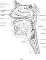
- the respiratory system of the body facilitates gas exchange.
- the nose and mouth form the entrance to the airways of a patient.
- the airways include a series of branching tubes, which become narrower, shorter and more numerous as they penetrate deeper into the lung.
- the prime function of the lung is gas exchange, allowing oxygen to move from the air into the venous blood and carbon dioxide to move out.
- the trachea divides into right and left main bronchi, which further divide eventually into terminal bronchioles.
- the bronchi make up the conducting airways, and do not take part in gas exchange. Further divisions of the airways lead to the respiratory bronchioles, and eventually to the alveoli.
- the alveolated region of the lung is where the gas exchange takes place, and is referred to as the respiratory zone. See " Respiratory Physiology", by John B. West, Lippincott Williams & Wilkins, 9th edition published 2011 .
- a range of respiratory disorders exist. Certain disorders may be characterised by particular events, e.g. apneas, hypopneas, and hyperpneas.
- Obstructive Sleep Apnea a form of Sleep Disordered Breathing (SDB), is characterized by events including occlusion or obstruction of the upper air passage during sleep. It results from a combination of an abnormally small upper airway and the normal loss of muscle tone in the region of the tongue, soft palate and posterior oropharyngeal wall during sleep.
- the condition causes the affected patient to stop breathing for periods typically of 30 to 120 seconds in duration, sometimes 200 to 300 times per night. It often causes excessive daytime somnolence, and it may cause cardiovascular disease and brain damage.
- the syndrome is a common disorder, particularly in middle aged overweight males, although a person affected may have no awareness of the problem. See US Patent No. 4,944,310 (Sullivan ).
- CSR Cheyne-Stokes Respiration
- CSR cycles rhythmic alternating periods of waxing and waning ventilation known as CSR cycles.
- CSR is characterised by repetitive de-oxygenation and re-oxygenation of the arterial blood. It is possible that CSR is harmful because of the repetitive hypoxia. In some patients CSR is associated with repetitive arousal from sleep, which causes severe sleep disruption, increased sympathetic activity, and increased afterload. See US Patent No. 6,532,959 (Berthon-Jones ).
- Obesity Hyperventilation Syndrome is defined as the combination of severe obesity and awake chronic hypercapnia, in the absence of other known causes for hypoventilation. Symptoms include dyspnea, morning headache and excessive daytime sleepiness.
- COPD Chronic Obstructive Pulmonary Disease
- COPD encompasses any of a group of lower airway diseases that have certain characteristics in common. These include increased resistance to air movement, extended expiratory phase of respiration, and loss of the normal elasticity of the lung. Examples of COPD are emphysema and chronic bronchitis. COPD is caused by chronic tobacco smoking (primary risk factor), occupational exposures, air pollution and genetic factors. Symptoms include: dyspnea on exertion, chronic cough and sputum production.
- Neuromuscular Disease is a broad term that encompasses many diseases and ailments that impair the functioning of the muscles either directly via intrinsic muscle pathology, or indirectly via nerve pathology.
- Some NMD patients are characterised by progressive muscular impairment leading to loss of ambulation, being wheelchair-bound, swallowing difficulties, respiratory muscle weakness and, eventually, death from respiratory failure.
- Neuromuscular disorders can be divided into rapidly progressive and slowly progressive: (i) Rapidly progressive disorders: Characterised by muscle impairment that worsens over months and results in death within a few years (e.g.
- ALS Amyotrophic lateral sclerosis
- DMD Duchenne muscular dystrophy
- Variable or slowly progressive disorders Characterised by muscle impairment that worsens over years and only mildly reduces life expectancy (e.g. Limb girdle, Facioscapulohumeral and Myotonic muscular dystrophy).
- Symptoms of respiratory failure in NMD include: increasing generalised weakness, dysphagia, dyspnea on exertion and at rest, fatigue, sleepiness, morning headache, and difficulties with concentration and mood changes.
- Chest wall disorders are a group of thoracic deformities that result in inefficient coupling between the respiratory muscles and the thoracic cage.
- the disorders are usually characterised by a restrictive defect and share the potential of long term hypercapnic respiratory failure.
- Scoliosis and/or kyphoscoliosis may cause severe respiratory failure.
- Symptoms of respiratory failure include: dyspnea on exertion, peripheral oedema, orthopnea, repeated chest infections, morning headaches, fatigue, poor sleep quality and loss of appetite.
- a range of therapies have been used to treat or ameliorate such conditions. Furthermore, otherwise healthy individuals may take advantage of such therapies to prevent respiratory disorders from arising. However, these have a number of shortcomings.
- Continuous Positive Airway Pressure (CPAP) therapy has been used to treat Obstructive Sleep Apnea (OSA).
- OSA Obstructive Sleep Apnea
- CPAP Continuous Positive Airway Pressure
- Treatment of OSA by CPAP therapy may be voluntary, and hence patients may elect not to comply with therapy if they find devices used to provide such therapy one or more of: uncomfortable, difficult to use, expensive and aesthetically unappealing.
- Non-invasive ventilation provides ventilatory support to a patient through the upper airways to assist the patient in taking a full breath and/or maintain adequate oxygen levels in the body by doing some or all of the work of breathing.
- the ventilatory support is provided via a patient interface.
- NIV has been used to treat CSR, OHS, COPD, MD and Chest Wall disorders. In some forms, the comfort and effectiveness of these therapies may be improved.
- IV Invasive ventilation
- These therapies may be provided by a treatment system or device.
- Systems and devices may also be used to diagnose a condition without treating it.
- a treatment system may comprise a Respiratory Pressure Therapy Device (RPT device), an air circuit, a humidifier, a patient interface, and data management.
- RPT device Respiratory Pressure Therapy Device
- Another form of treatment system is a mandibular repositioning device.
- a patient interface may be used to interface respiratory equipment to its wearer, for example by providing a flow of air to an entrance to the airways.
- the flow of air may be provided via a mask to the nose and/or mouth, a tube to the mouth or a tracheostomy tube to the trachea of a patient.
- the patient interface may form a seal, e.g., with a region of the patient's face, to facilitate the delivery of gas at a pressure at sufficient variance with ambient pressure to effect therapy, e.g., at a positive pressure of about 10 cmH 2 O relative to ambient pressure.
- the patient interface may not include a seal sufficient to facilitate delivery to the airways of a supply of gas at a positive pressure of about 10 cmH 2 O.
- the design of a patient interface presents a number of challenges.
- the face has a complex three-dimensional shape.
- the size and shape of noses varies considerably between individuals. Since the head includes bone, cartilage and soft tissue, different regions of the face respond differently to mechanical forces.
- the jaw or mandible may move relative to other bones of the skull. The whole head may move during the course of a period of respiratory therapy.
- masks designed solely for aviators, masks designed as part of personal protection equipment (e.g. filter masks), SCUBA masks, or for the administration of anaesthetics may be tolerable for their original application, but nevertheless such masks may be undesirably uncomfortable to be worn for extended periods of time, e.g., several hours. This discomfort may lead to a reduction in patient compliance with therapy. This is even more so if the mask is to be worn during sleep.
- CPAP therapy is highly effective to treat certain respiratory disorders, provided patients comply with therapy. If a mask is uncomfortable, or difficult to use a patient may not comply with therapy. Since it is often recommended that a patient regularly wash their mask, if a mask is difficult to clean (e.g., difficult to assemble or disassemble), patients may not clean their mask and this may impact on patient compliance.
- a mask for other applications may not be suitable for use in treating sleep disordered breathing
- a mask designed for use in treating sleep disordered breathing may be suitable for other applications.
- patient interfaces for delivery of CPAP during sleep form a distinct field.
- Patient interfaces may include a seal-forming portion. Since it is in direct contact with the patient's face, the shape and configuration of the seal-forming portion can have a direct impact the effectiveness and comfort of the patient interface.
- a patient interface may be partly characterised according to the design intent of where the seal-forming portion is to engage with the face in use.
- a seal-forming portion may comprise two sub-portions to engage with respective left and right nares.
- a seal-forming portion may comprise a single element that surrounds both nares in use. Such single element may be designed to for example overlay an upper lip region and a nasal bridge region of a face.
- a seal-forming portion may comprise an element that surrounds a mouth region in use, e.g. by forming a seal on a lower lip region of a face.
- a seal-forming portion may comprise a single element that surrounds both nares and a mouth region in use.
- These different types of patient interfaces may be known by a variety of names by their manufacturer including nasal masks, full-face masks, nasal pillows, nasal puffs and oro-nasal masks.
- a seal-forming portion that may be effective in one region of a patient's face may be inappropriate in another region, e.g. because of the different shape, structure, variability and sensitivity regions of the patient's face.
- a seal on swimming goggles that overlays a patient's forehead may not be appropriate to use on a patient's nose.
- Certain seal-forming portions may be designed for mass manufacture such that one design fit and be comfortable and effective for a wide range of different face shapes and sizes. To the extent to which there is a mismatch between the shape of the patient's face, and the seal-forming portion of the mass-manufactured patient interface, one or both must adapt in order for a seal to form.
- seal-forming portion extends around the periphery of the patient interface, and is intended to seal against the patient's face when force is applied to the patient interface with the seal-forming portion in confronting engagement with the patient's face.
- the seal-forming portion may include an air or fluid filled cushion, or a moulded or formed surface of a resilient seal element made of an elastomer such as a rubber.
- seal-forming portion incorporates a flap seal of thin material positioned about the periphery of the mask so as to provide a self-sealing action against the face of the patient when positive pressure is applied within the mask.
- flap seal of thin material positioned about the periphery of the mask so as to provide a self-sealing action against the face of the patient when positive pressure is applied within the mask.
- additional force may be required to achieve a seal, or the mask may leak.
- shape of the seal-forming portion does not match that of the patient, it may crease or buckle in use, giving rise to leaks.
- seal-forming portion may comprise a friction-fit element, e.g. for insertion into a naris, however some patients find these uncomfortable.
- seal-forming portion may use adhesive to achieve a seal. Some patients may find it inconvenient to constantly apply and remove an adhesive to their face.
- nasal pillow is found in the Adam Circuit manufactured by Puritan Bennett.
- Another nasal pillow, or nasal puff is the subject of US Patent 4,782,832 (Trimble et al .), assigned to Puritan-Bennett Corporation.
- ResMed Limited has manufactured the following products that incorporate nasal pillows: SWIFT TM nasal pillows mask, SWIFT TM II nasal pillows mask, SWIFT TM LT nasal pillows mask, SWIFT TM FX nasal pillows mask and MIRAGE LIBERTY TM full-face mask.
- a seal-forming portion of a patient interface used for positive air pressure therapy is subject to the corresponding force of the air pressure to disrupt a seal.
- a variety of techniques have been used to position the seal-forming portion, and to maintain it in sealing relation with the appropriate portion of the face.
- Another technique is the use of one or more straps and/or stabilising harnesses. Many such harnesses suffer from being one or more of ill-fitting, bulky, uncomfortable and awkward to use.
- Some forms of patient interface systems may include a vent to allow the washout of exhaled carbon dioxide.
- the vent may allow a flow of gas from an interior space of the patient interface, e.g., the plenum chamber, to an exterior of the patient interface, e.g., to ambient.
- the vent may comprise an orifice and gas may flow through the orifice in use of the mask. Many such vents are noisy. Others may become blocked in use and thus provide insufficient washout.
- Some vents may be disruptive of the sleep of a bed-partner 1100 of the patient 1000, e.g. through noise or focussed airflow.
- ResMed Limited has developed a number of improved mask vent technologies. See International Patent Application Publication No. WO 1998/034,665 ; International Patent Application Publication No. WO 2000/078,381 ; US Patent No. 6.581.594 ; US Patent Application Publication No. US 2009/0050156 ; US Patent Application Publication No. 2009/0044808 .
- a mandibular repositioning device (MRD) or mandibular advancement device (MAD) is one of the treatment options for sleep apnea and snoring. It is an adjustable oral appliance available from a dentist or other supplier that holds the lower jaw (mandible) in a forward position during sleep.
- the MRD is a removable device that a patient inserts into their mouth prior to going to sleep and removes following sleep. Thus, the MRD is not designed to be worn all of the time.
- the MRD may be custom made or produced in a standard form and includes a bite impression portion designed to allow fitting to a patient's teeth. This mechanical protrusion of the lower jaw expands the space behind the tongue, puts tension on the pharyngeal walls to reduce collapse of the airway and diminishes palate vibration.
- a mandibular advancement device may comprise an upper splint that is intended to engage with or fit over teeth on the upper jaw or maxilla and a lower splint that is intended to engage with or fit over teeth on the lower jaw or mandible.
- the upper and lower splints are connected together laterally via a pair of connecting rods.
- the pair of connecting rods is fixed symmetrically on the upper splint and on the lower splint.
- the length of the connecting rods is selected such that when the MRD is placed in a patient's mouth the mandible is held in an advanced position.
- the length of the connecting rods may be adjusted to change the level of protrusion of the mandible.
- a dentist may determine a level of protrusion for the mandible that will determine the length of the connecting rods.
- MRDs are structured to push the mandible forward relative to the maxilla while other MADs, such as the ResMed Narval CC TM MRD are designed to retain the mandible in a forward position.
- This device also reduces or minimises dental and temporo-mandibular joint (TMJ) side effects. Thus, it is configured to minimises or prevent any movement of one or more of the teeth.
- a substantially air tight seal should be provided by the seal forming structure.
- patient comfort is also desirable.
- it is not desirable to firmly press the seal forming structure against the patient's face as this may result in pressure marks, pressure sores and pain of the patient; in particular, as the respective devices are typically worn for several hours, e.g. the complete duration of the night's sleep.
- this may also result in the patient not being compliant with the therapy. That is. it is generally a desire to provide a seal forming structure, which, at the same time, firmly seals an interior of the patient interface from an exterior of the patient interface and, is also comfortable for the patient to wear.
- WO 2007/104042 A2 relates to a seal that contacts a portion of a patient to provide a comfortable interface between an external device, such as a respiratory mask, and the patient, wherein the seal includes an elastic casing filled with a soft gel substance having a cone penetration of from about 5 to 200 penetrations.
- WO 2009/062265 A1 relates to a cushion assembly for use with a respiratory mask including a bladder filled with the combination of a gel having a first indentation hardness and a gel having a second indentation hardness.
- WO2014125066 describes a medical support comprising a sheet of heat moldable thermoplastic material and a removable device.
- a user formable element for a patient interface.
- Such patient interface is preferably adapted and suitable for treatment of disordered breathing sleep using air pressure and for delivering air, particularly pressurized air, to a patient's airway.
- the user formable element may be a seal forming structure.
- the user formable element comprises, in particular, a section of a thermo-formable material. That is a material having a relatively low softening or transition temperature, such as polycaprolactane (PCL).
- PCL polycaprolactane
- Such an element can then be fitted by a user to the individual physiological facial characteristics to fit the patient interface or at least the user formable element to the individual patient. This may provide more comfortable seating and/or improved sealing of the interface on a patient's face, particularly during therapy of sleep disordered breathing using air pressure.
- the shaping of the formable material is intended to occur following known procedures for such materials, such as heating in warm water, by infrared radiation, microwave radiation or other means of heating available in the user's household.
- thermo-formable material has properties enabling it to soften when exposed to increased temperatures, such as 40°C-100°C, and to solidify again as the temperature drops below a certain threshold.
- the transition temperature of the material may be sufficiently low so that sustained contact with the patient's face during the forming stage is advantageously possible without, e.g., causing pain or skin damage due to the material's temperature.
- the user may heat either only the user formable element, such as the seal forming structure, and/or the entire mask system, then apply the heated section to his or her face so that it adapts to the physical characteristics. Finally, the user formable element is cooled again so that it retains the new, customized shape which now effectively corresponds to the patient's physiognomy.
- the material is not necessarily actively cooled, e.g. by commonly known measures, such as by immersion in a liquid or a gas of lower temperature, or by exposure to a cooling air flow or the like.
- the temperature drop below the transition temperature threshold may also occur due to passive cooling, i.e. passive heat dissipation due to the material cooling off by itself due to heat dissipation into ambient.
- the material of user formable element may not suffice as a material for the seal forming structure, due to, for example, its handling issues, lack of softness, lack of elasticity, etc.
- it is therefore intended to combine the user formable element with other materials, such a polycarbonate, polyamide, polybutylene terephthalate, and others.
- other known soft and elastic materials such as silicone, thermoplastic elastomers, foams, and others, may also be used to produce the seal forming structure.
- the present technology may therefore improve the fit and functioning of existing respiratory masks and add the benefit of providing the user with means for adaptation to his individual physiognomy.
- the advantages of the present technology include an improved mask fit and seal, improved comfort through individualized fit, reduction of pressure points and pressure sores. Furthermore, with the manufacturing methods disclosed herein, the devices may also be produced in an efficient manner.
- the present technology is generally directed towards providing medical devices used in the diagnosis, amelioration, treatment, or prevention of respiratory disorders having one or more of improved comfort, cost, efficacy, ease of use and manufacturability.
- a first aspect of the present technology relates to apparatus used in the diagnosis, amelioration, treatment or prevention of a respiratory disorder.
- Another aspect of the present technology relates to methods used in the diagnosis, amelioration, treatment or prevention of a respiratory disorder.
- An aspect of certain forms of the present technology is to provide methods and/or apparatus that improve the compliance of patients with respiratory therapy.
- An aspect of one form of the present technology is a method of manufacturing apparatus.
- An aspect of one form of the present technology is a portable RPT device that may be carried by a person, e.g., around the home of the person.
- An aspect of one form of the present technology is a patient interface that may be washed in a home of a patient, e.g., in soapy water, without requiring specialised cleaning equipment.
- An aspect of one form of the present technology is a humidifier tank that may be washed in a home of a patient, e.g., in soapy water, without requiring specialised cleaning equipment.
- portions of the aspects may form sub-aspects of the present technology.
- various ones of the sub-aspects and/or aspects may be combined in various manners and also constitute additional aspects or sub-aspects of the present technology.
- the first section includes a thermoformable material and this embodiment is discussed in greater detail below, it is to be understood that the present technology is not limited to such materials. Instead, other user-formable materials may also be used - instead of applying heat to the user-formable material, it may also be possible that other measures are applied thereto to bring the material in a transition state (i.e. a state where the user may deform it). Non-limiting examples of bringing the material to the transition state include the application of pressure, force, humidity, voltage or current.
- thermoformable material there are different amounts (i.e. areas) of thermoformable material in different cross sections along the perimeter. Such amounts may vary in thickness, width, or cross-sectional geometry.
- the present technology comprises a method for treating a respiratory disorder comprising the step of applying positive pressure to the entrance of the airways of a patient 1000.
- a supply of air at positive pressure is provided to the nasal passages of the patient via one or both nares.
- mouth breathing is limited, restricted or prevented.
- the present technology comprises an apparatus or device for treating a respiratory disorder.
- the apparatus or device may comprise an RPT device 4000 for supplying pressurised air to the patient 1000 via an air circuit 4170 to a patient interface 3000.
- a non-invasive patient interface 3000 in accordance with one aspect of the present technology comprises the following functional aspects: a seal-forming structure 3100, a plenum chamber 3200, a positioning and stabilising structure 3300 and one form of connection port 3600 for connection to air circuit 4170.
- a functional aspect may be provided by one or more physical components.
- one physical component may provide one or more functional aspects.
- the seal-forming structure 3100 is arranged to surround an entrance to the airways of the patient so as to facilitate the supply of air at positive pressure to the airways.
- a seal-forming structure 3100 provides a seal-forming surface, and may additionally provide a cushioning function.
- a seal-forming structure 3100 in accordance with the present technology may be constructed from a soft, flexible, resilient material such as silicone.
- the seal-forming structure 3100 comprises a sealing flange 3110 and a support flange 3120.
- the sealing flange 3110 comprises a relatively thin member with a thickness of less than about 1mm. for example about 0.25mm to about 0.45mm. that extends around the perimeter 3210 of the plenum chamber 3200.
- Support flange 3120 may be relatively thicker than the sealing flange 3110.
- the support flange 3120 is disposed between the sealing flange 3110 and the marginal edge 3220 of the plenum chamber 3200, and extends at least part of the way around the perimeter 3210.
- the support flange 3120 is or includes a spring-like element and functions to support the sealing flange 3110 from buckling in use. In use the sealing flange 3110 can readily respond to system pressure in the plenum chamber 3200 acting on its underside to urge it into tight sealing engagement with the face.
- the seal-forming portion of the non-invasive patient interface 3000 comprises a pair of nasal puffs, or nasal pillows, each nasal puff or nasal pillow being constructed and arranged to form a seal with a respective naris of the nose of a patient.
- Nasal pillows in accordance with an aspect of the present technology include: a frusto-cone, at least a portion of which forms a seal on an underside of the patient's nose, a stalk, a flexible region on the underside of the frusto-cone and connecting the frusto-cone to the stalk.
- the structure to which the nasal pillow of the present technology is connected includes a flexible region adjacent the base of the stalk.
- the flexible regions can act in concert to facilitate a universal joint structure that is accommodating of relative movement both displacement and angular of the frusto-cone and the structure to which the nasal pillow is connected.
- the frusto-cone may be axially displaced towards the structure to which the stalk is connected.
- the non-invasive patient interface 3000 comprises a seal-forming portion that forms a seal in use on an upper lip region (that is, the lip superior ) of the patient's face.
- the non-invasive patient interface 3000 comprises a seal-forming portion that forms a seal in use on a chin-region of the patient's face.
- the plenum chamber 3200 has a perimeter 3210 that is shaped to be complementary to the surface contour of the face of an average person in the region where a seal will form in use. In use, a marginal edge 3220 of the plenum chamber 3200 is positioned in close proximity to an adjacent surface of the face. Actual contact with the face is provided by the seal-forming structure 3100.
- the seal-forming structure 3100 may extend in use about the entire perimeter 3210 of the plenum chamber 3200.
- the seal-forming portion 3100 of the patient interface 3000 of the present technology may be held in sealing position in use by the positioning and stabilising structure 3300.
- a positioning and stabilising structure 3300 is provided that is configured in a manner consistent with being worn by a patient while sleeping.
- the positioning and stabilising structure 3300 has a low profile, or cross-sectional thickness, to reduce the perceived or actual bulk of the apparatus.
- the positioning and stabilising structure 3300 comprises at least one strap having a rectangular cross-section.
- the positioning and stabilising structure 3300 comprises at least one flat strap.
- a positioning and stabilising structure 3300 comprises a strap constructed from a laminate of a fabric patient-contacting layer, a foam inner layer and a fabric outer layer.
- the foam is porous to allow moisture, (e.g., sweat), to pass through the strap.
- the fabric outer layer comprises loop material to engage with a hook material portion.
- a positioning and stabilising structure 3300 comprises a strap that is extensible, e.g. resiliently extensible.
- the strap may be configured in use to be in tension, and to direct a force to draw a cushion into sealing contact with a portion of a patient's face.
- the strap may be configured as a tie.
- a positioning and stabilising structure 3300 comprises a strap that is bendable and e.g. non-rigid.
- An advantage of this aspect is that the strap is more comfortable for a patient to lie upon while the patient is sleeping.
- the patient interface 3000 includes a vent 3400 constructed and arranged to allow for the washout of exhaled carbon dioxide.
- vent 3400 in accordance with the present technology comprises a plurality of holes, for example, about 20 to about 80 holes, or about 40 to about 60 holes, or about 45 to about 55 holes.
- the vent 3400 may be located in the plenum chamber 3200.
- the vent 3400 is located in a decoupling structure 3500, e.g., a swivel 3510.
- the patient interface 3000 includes at least one decoupling structure 3500, for example, a swivel 3510 or a ball and socket 3520.
- Connection port 3600 allows for connection to the air circuit 4170.
- the patient interface 3000 includes a forehead support 3700.
- the patient interface 3000 includes an anti-asphyxia valve 3800.
- a patient interface 3000 includes one or more ports that allow access to the volume within the plenum chamber 3200. In one form this allows a clinician to supply supplemental oxygen. In one form, this allows for the direct measurement of a property of gases within the plenum chamber 3200, such as the pressure.
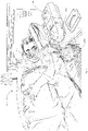
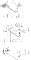
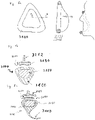
- FIG. 5a shows one aspect in accordance with the present technology.
- a seal forming structure 3100 of a patient interface 3000 is provided.
- This seal forming structure 3100 may be a user formable pad preferably consisting of or comprising a thermo-formable material.
- heat e.g., heat (depicted as wavy lines) may be applied to seal forming structure 3100, such that this seal forming structure 3100 softens.
- the present specification is in particular and preferably directed to a thermo-formable structure.
- the present technology may also be employed be means of other user formable structures.
- the seal forming structure 3100 may then, in this softened state, be applied to a patient's face (see right depiction in Figure 5a ) and assume the approximate shape of the patient's face. When the seal forming structure 3100 cools down again, it will remain in this shape. Thereby, an individual or customized shape and thus fit of the seal forming structure on this particular user's face is achieved.
- the seal forming structure 3100 may have a thermo-formable section 3150 (see, e.g., Figure 4a and 4b ).
- This section may be made of a material having a specific transition temperature. Below this transition temperature, which may also be referred to as a melting temperature or as a softening point, the material maintains its shape. Above this transition temperature, the material may be deformed. Typically, this transition temperature is above the temperature a patient interface 3000 typically assumes in use. That is, this transition temperature may be, e.g., in the range of 40°C-100°C.
- a user may heat the seal forming structure 3100 (either on its own or with the remainder of the patient interface 3000) above the transition temperature, e.g., by means of warm water, infrared radiation, microwave radiation or other means of heating available in the user's household and then deform the seal forming structure 3100. preferably by applying it to or pressing it on his or her face.
- the seal forming structure 3100 then cools down again below the transition temperature, it will maintain the respective shape.
- the seal forming structure may better fit to the patient's physiognomy of the face.
- a better sealing may be achieved and a more comfortable fit of the patient interface 3000 to the user.
- a patient interface 3000 typically comprises a shell 3250. If the patient interface 3000 is realized as a mask, this shell 3250 may also be referred to as a chassis or as a mask chassis.
- the shell 3250 may be formed from a relatively rigid material, such as polycarbonate. However, other materials, such as polyamide, polybutylene terephthalate and/or others may also be used for this embodiment and the other embodiments of the present technology.
- the patient interface 3000 also comprises a connection port 3600 for connection to a breathing gas line.
- connection port 3600 may either be adapted for direct connection of a breathing gas line or for indirect connection to such a breathing gas line, e.g., by means of a swivel elbow.
- the patient interface 3000 may also comprise a vent 3400 including a plurality of apertures for washing out a exhaled air.
- the embodiment depicted in Figures 4a and 4b also comprises a seal forming structure 3100, such as a pad.
- This seal forming structure 3100 includes the thermo-formable section 3150.
- the seal forming structure 3100 also comprises a second portion 3160 of another material.
- this section of another material completely surrounds or encloses the thermo-formable section 3150, which may therefore also be referred to, in this embodiment, as a thermo-formable core section.
- the second section 3160 is adapted to come into contact with a patient's face during use of the patient interface 3100.
- the second section 3160 is therefore preferably formed of a skin-friendly and/or seal enhancing material, such as, for example, silicon.
- the patient interface also comprises a carrier portion 3252 or cushion structure. One end of the carrier portion 3252 may be T-shaped. The carrier portion 3252 may be formed integrally with shell 3250.
- carrier portion 3252 may also be formed from another material than shell 3250.
- carrier portion 3252 may also be formed of a material being more resilient then shell 3252 to allow, e.g., for bending of the carrier portion 3252.
- carrier portion 3252 may have a T-shaped end section - also see Figures 5b and 5c being sections along line A-A of Figure 5a .
- Such an end section may include a platform region 3254 (preferably the T-beam of the T-shape cross sectional structure), which may be generally flat.
- the seal forming structure 3100 may be applied to this platform region 3254, e.g., by means of an adhesive such as an adhesive strip 3190.
- seal forming structure 3100 may also have a substantially flat end section to allow for easy connection to platform region 3254 by means of adhesive 3190.
- Figures 5b and 5c depict the cross-section of different embodiments.
- the main difference of the two embodiments depicted in Figures 5b and 5c resides in the fact that the seal forming structure 3100 of the embodiment in Figure 5c includes a sealing flange 3110.
- This sealing flange 3110 may also be referred to as a sealing membrane or as a sealing lip.
- This sealing flange 3110 is a structure comprising, in a cross sectional view as depicted in Figure 5c , an elongation which is substantially larger than its thickness.
- the sealing flange 3110 may also be referred to as being a thin section.
- the sealing flange 3110 may allow for a particularly safe and comfortable seal between the patient interface and the user's face.
- the sealing flange 3110 is formed integrally with the second section 3160. That is, in other words, the sealing flange 3110 is formed as a part of this second section 3160.
- thermo-formable section 3150 may be completely enclosed by, surrounded by or embedded within the second section 3160.
- second material of section 3160 of seal forming structure 3100 may be exposed to the outside.
- a patient using this patient interface may only come into contact with second section 3160, but not with the thermo-formable section 3150.
- This may be beneficial, as the patient, when handling seal forming structure 3100, would only come into contact with the section 3160, which may be generally formed of skin-friendly material.
- This may broaden the choice of thermo-formable materials to be used for thermo-formable section 3150.
- it may also give the patient a more comfortable feel of the seal forming structure 3100, as the patient only comes into contact with materials, which are already known to him. In particular, this may also improve patient compliance.
- seal forming structure 3100 e.g., a user formable pad
- a carrier portion 3252 that is a carrier system, preferably by means of adhesive.
- the shaping of the seal forming structure 3100 will transfer to the carrier system by deforming the respective component.
- the seal forming structure 3100 may be substantially flat and shaped suitable to correspond to the carrier portion 3252. This may also include the additional advantages of the respective seal forming structure 3100 being replaceable and enabling an upgrade of existing patient interfaces.
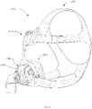
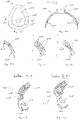
- Figure 6a again depicts the general outline of a patient interface 3000 including a shell or chassis 3250 and a seal forming structure 3100. Again, a connection portion 3600 for connection of a tube or an elbow is included.
- Figure 6b depicts a cross-sectional view along line A-A of Figure 6a . It should be noted that Figures 6a and 6b (as well as Figures 6c to 6e ) depict a patient interface 3000 (or parts/details thereof) during the manufacturing process, that is before the patient interface is ready for use by a patient.
- the seal forming structure 3100 is not yet completely formed in these Figures 6a to 6e .
- the patient interface 3000 to be formed includes the shell 3250 and the thermo-formable section 3250 of seal forming structure 3100.
- the shell 3250 and the thermo-formable section 3150 may be connected to each other in a variety of ways, as depicted in Figures 6c to 6e .
- the respective section of the shell 3250 may also be referred to as a substrate, onto which the thermo-formable section 3150 is applied.
- a molded mechanical interlock 3258 for connection of the shell or substrate 3250 and the thermo-formable section 3150. This may be achieved by provision of a grid like structure comprising holes between structural sections 3258.
- the tool sections may also be connected to each other by means of a mechanical interlock 3260, such as a snap fit, as depicted in Figure 6e .
- a mechanical interlock 3260 such as a snap fit
- thermo-formable section 3150 may have a generally elongated shape. That is, in a cross sectional view, one dimension of the thermo-formable section may be substantially larger than another dimension. In this regard, the thermo-formable section 3150 may be thin. In other words, the thermo-formable section 3150 may also be referred to as a fin 3150.
- Fig. 6a shows a frontal view of a mask chassis with a thermoformable fin around the entire circumference
- Fig. 6b a cross section of same
- Figs 6c to 6e illustrate different details of means of connection between chassis and thermoformable fin
- Fig 6f shows a chassis and thermoformable fin (which may use any of the principles, e.g. as shown in and discussed with regard to Figs. 6c to 6e ) overmoulded in silicone to form a mask cushion.
- Fig 6g shows a detail of a cross sections of the thermoformable fin deformed after the adaption process.
- Figures 6a-6e depict the patient interface 3000 in an intermediate state of the production process.
- a second material is applied to the patient interface 3000 to form the second section 3160 of seal forming structure 3100, here not simply a pad but a cushion-structure.
- a pad includes reference to a cushion and vice-versa.
- typically a material suitable for skin contact, that is skin-friendly material may be used for the material of the second section 3160.
- silicon may be used.
- this second section 3160 of seal forming structure 3100 may be applied to the other parts by means of over molding. That is, the two component part depicted in Figures 6a-6e may be inserted into a tool for over molding and may be over molded, e.g., with silicon, to form the seal forming structure 3100, such as the pad or cushion. Thus, a three component (3K) patient interface would be formed with a thermo-formable element.
- thermo-formable section that is, in this embodiment, the thermo-formable fin
- the thermo-formable section may also be (pre-)shaped to match a patient's generalized physiognomy quite closely, thereby limiting the amount of shaping required to achieve the adaptation to individual features.
- Fig. 6f shows a preferred structure before heating and customization while Fig. 6g shows the same preferred structure after thermoforming.
- Figures 6f and 6g show two cross sectional views along, e.g., lines A-A and B-B (which are basically identical cross sections but simply refer to different points in time, i.e. one before A-A and one after thermoforming B-B) of Figure 6a , however, only after over-molding with a second material. While Fig. 6a shows the structure before thermoforming, Fig. 6b shows the structure after shaping by a patient has taken place. As will be apparent, the part of the thermo-formable section 3150 in Figure 6g has been deformed vis-à-vis the former state of the thermo-formable section 3150 as seen in Figure 6f .
- thermo-formable section 3150 in Figure 6f has a thin, fin-like shape
- the part of the thermo-formable section 3150 in Figure 6g has been compressed to adopt a more bulky cross-sectional shape. That is, in other words, the amount of forming required may not be uniform around the perimeter of the patient interface. Instead, there may be areas with more deformation and/or deflection and other areas with less deformation and/or deflection.
- Figures 6f and 6g also depict the seal forming structure 3100 to comprise both a sealing flange 3110 and a support flange 3120. These may be formed integrally with the second section 3160. In other words, these sections may also be referred to be part of the second section 3100, that is, in other words, the second section 3160 comprises the sealing flange 3110 and the support flange 3120.
- sealing flange e.g.
- membrane 3110 and undercushion 3120 in this embodiment is only exemplary - that is, the skilled person may also not include these features in the present embodiment or may, alternatively, include the features of a sealing flange 3110 and a support flange 3120 in the other embodiments, such as the embodiment depicted in Figure 4a to 5b .
- thermo-formable material 3150 may be completely surrounded by other material. That is, all the surface sections of the thermo-formable section 3150 not being in contact with substrate 3250 are in contact with second section 3160 of seal forming structure 3100. In other words, no portion of the thermo-formable section 3150 is exposed to ambient, such that the user will not come into contact with thermo-formable section 3150, such that the user only comes to contact with material he is used tom, which may improve, e.g., user compliance. In other words, as depicted and discussed, part of the thermo-formable material may not be covered or surrounded by second material or section 3160 of seal forming structure 3100 but in contact with and covered by substrate 3250.
- Figures 7a to 7c depict yet another embodiment of the present technology.
- Figures 7a and 7b depict the patient interface 3100 before the final step of over molding
- Figure 7c depicts the patient interface 3000 after over-molding has taken place.
- the patient interface 3000 to be formed includes a shell or chassis 3250 with a connection port 3600 (also see the sectional view of Figure 7b ).
- the patient interface 3000 again comprises a thermo-formable section 3150.
- the thermo-formable section 3150 includes a perimeter section 3152 and a plurality of leg members or web portions 3154 connecting the perimeter section 3152 to the mask shell 3250.
- web portions 3154 there are provided three web portions 3154, however, the skilled person will understand that also a different number of web portions 3154, such as 2, 4, 5 or more web portions may be provided.
- the web portions 3154 are preferably also made of the thermo-formable material, but may also be made of another material.
- Figure 7c again depicts a cross sectional view along line A-A of Figure 7a after over molding has taken place.
- this embodiment comprises a seal forming structure 3100 including a thermo-formable section 3150 and a second section 3160.
- the second section 3160 may include a sealing flange 3110 and may include a support flange 3120.
- the patient interface may be formed in such a way that no section of the thermo-formable section 3150 is exposed to ambient, but the thermo-formable section 3150 is completely enclosed by the shell 3250 (at the connection points) and by the second section 3160 of the seal forming structure 3100.
- thermo-formable section is not connected or bonded to the shell 3250 (or substrate) around the entire perimeter, but only in selected locations, e.g., at the web portions 3154. This may improve the forming range of the user formable seal forming structure 3100.
- thermo-formable section 3150 which may also be fin-shaped, may protrude further away from the shell 3250, thereby adding additional degrees of freedom to the shaping.
- the perimeter section 3150 may be in the shape of a fin, however, it may also take another shape and be referred to as a frame or stiffener portion 3152.
- thermo-formable section 3150 in the lower half of this cross sectional view, there is no direct connection between the thermo-formable section 3150 and the shell or substrate 3250. Instead, the gap G of Figure 7b is filled with the material of the second section 3160, such as silicon, during the over molding process, resulting in a larger extension of the second section 3160 contributing to a larger adjustment range.
- the material of the second section 3160 such as silicon
- Figures 8a and 8b show another embodiment of the present technology, Figure 8b being an enlarged view of a detail of Figure 8a .
- the patient interface 3000 of this embodiment includes a shell or chassis 3250 with a connection port 3600.
- the patient interface 3000 also includes a seal forming structure 3100, which may include a sealing flange 3110 and which may also include a support flange 3120. as discussed above (although these structures do not necessarily need to be provided).
- the seal forming structure 3100 includes a pocket or groove 3130 adapted for receiving a thermo-formable section 3150.
- the shell 3250 and the seal forming structure 3100 define together a plenum chamber 3200.
- seal forming structure 3100 and shell 3250 limit, together with a patient's face, a certain space, that is the plenum chamber 3200.
- This section may also be referred to as the interior of the patient interface.
- the groove or pocket 3130 is only accessibly from the patient interface's outside 3270.
- the pocket or groove 3130 is provided on the outside 3250 of the patient interface 3000.
- the groove 3130 may be provided with at least one undercut 3132 and preferably a plurality of undercuts 3132, that is. e.g., two undercuts 3132, forming a mechanical interlock feature to prevent the thermo-formable section 3135 from coming loose during forming.
- a chemical bond can be formed between the thermo-formable section 3150 and the groove 3130.
- the shell or chassis 3250 and the section 3160 of the seal forming structure 3100 are molded in a two component molding process in such a way that the seal forming structure 3100 includes the groove or pocket 3130 into which thermo-formable material is introduced at a second stage after the molding, e.g., by means of potting and/or dosing processes.
- the section 3160 of the sealing structure may be silicon and the thermo-formable material may be polycaprolactane (PCL).
- thermo-formable section 3130 allows for an alternative manufacturing process, which is particularly easy and allows a simple introduction of the thermo-formable section 3130.
- Figure 9a depicts a manufacturing tool, such as a molding tool with two sections A and B.
- One of the two sections A and B is a movable section, while the other section is a fixed section of the tool.
- section B may be a fixed tool section
- section A may be a movable tool section.
- this tool there is placed an insert for a shell 3250 of the patient interface 3000 having a connection portion 3600.
- an insert for the seal forming structure 3100 in this tool.
- an insert of thermo-formable material 3150 is also placed in this tool. Near and around the insert for the thermo-formable section 3150, there is provided a gap of cavity 3174.
- the insert for the seal forming structure 3100 may include a pocket or cavity 3130 into which the insert of thermo-formable material 3150 is placed.
- thermo-formable material 3150 may be cast, pointed or dosed or molded into the groove 3130 or assembled as a separate component thereof.
- the resulting two-component-structure may be inserted into the tool A-B, together with the insert for the shell or chassis 3250. All these components may then be over molded in another step to complete the assembly. That is, a further material, such as silicon, is introduced to fill the cavity 3174 to connect the components with each other.
- a resulting patient interface 3000 is depicted in cross section in Figure 9b .
- this patient interface includes a shell or chassis 3250 with a connection port 3600, as well as a seal forming structure 3100, which may (or may not) comprise at least one of a sealing flange 3110 and a support flange 3120.
- the seal forming structure 3100 comprises a thermo-formable section 3150 and a second section 3160 of another material. Again, this second section may include the sealing flange 3110 and the support flange 3120.
- the seal forming structure 3100 of this embodiment also includes a third section 3164 connecting the seal forming structure 3100 to the shell 3250.
- the structure 3160 is depicted to be a structure separate from the connecting structure 3164 of seal forming structure 3100, these sections may be made of the same material, such as silicon. However, alternatively, these sections may also be made from different materials.
- This embodiment may allow for still another manufacturing process and a simple molding process, as well as simplicity of tooling.
- Air In certain forms of the present technology, air may be taken to mean atmospheric air, and in other forms of the present technology air may be taken to mean some other combination of breathable gases, e.g. atmospheric air enriched with oxygen.
- ambient In certain forms of the present technology, the term ambient will be taken to mean (i) external of the treatment system or patient, and (ii) immediately surrounding the treatment system or patient.
- ambient humidity with respect to a humidifier may be the humidity of air immediately surrounding the humidifier, e.g. the humidity in the room where a patient is sleeping. Such ambient humidity may be different to the humidity outside the room where a patient is sleeping.
- ambient pressure may be the pressure immediately surrounding or external to the body.
- ambient noise may be considered to be the background noise level in the room where a patient is located, other than for example, noise generated by an RPT device or emanating from a mask or patient interface.
- Ambient noise may be generated by sources outside the room.
- CPAP therapy will be taken to mean the application of a supply of air to an entrance to the airways at a pressure that is continuously positive with respect to atmosphere.
- the pressure may be approximately constant through a respiratory cycle of a patient.
- the pressure at the entrance to the airways will be slightly higher during exhalation, and slightly lower during inhalation.
- the pressure will vary between different respiratory cycles of the patient, for example, being increased in response to detection of indications of partial upper airway obstruction, and decreased in the absence of indications of partial upper airway obstruction.
- Patient A person, whether or not they are suffering from a respiratory disease.
- APAP therapy in which the treatment pressure is automatically adjustable, e.g. from breath to breath, between minimum and maximum limits, depending on the presence or absence of indications of SDB events.
- an apnea is said to have occurred when flow falls below a predetermined threshold for a duration, e.g. 10 seconds.
- An obstructive apnea will be said to have occurred when, despite patient effort, some obstruction of the airway does not allow air to flow.
- a central apnea will be said to have occurred when an apnea is detected that is due to a reduction in breathing effort, or the absence of breathing effort, despite the airway being patent.
- a mixed apnea occurs when a reduction or absence of breathing effort coincides with an obstructed airway.
- Breathing rate The rate of spontaneous respiration of a patient, usually measured in breaths per minute.
- Duty cycle The ratio of inhalation time, Ti to total breath time, Ttot.
- Breathing effort will be said to be the work done by a spontaneously breathing person attempting to breathe.
- Expiratory portion of a breathing cycle The period from the start of expiratory flow to the start of inspiratory flow.
- Flow limitation will be taken to be the state of affairs in a patient's respiration where an increase in effort by the patient does not give rise to a corresponding increase in flow. Where flow limitation occurs during an inspiratory portion of the breathing cycle it may be described as inspiratory flow limitation. Where flow limitation occurs during an expiratory portion of the breathing cycle it may be described as expiratory flow limitation.
- hypopnea will be taken to be a reduction in flow, but not a cessation of flow.
- a hypopnea may be said to have occurred when there is a reduction in flow below a threshold rate for a duration.
- a central hypopnea will be said to have occurred when a hypopnea is detected that is due to a reduction in breathing effort.
- hypopneas either of the following may be regarded as being hypopneas:
- Hyperpnea An increase in flow to a level higher than normal flow rate.
- Inspiratory portion of a breathing cycle The period from the start of inspiratory flow to the start of expiratory flow will be taken to be the inspiratory portion of a breathing cycle.
- Patency airway
- Airway patency may be quantified, for example with a value of one (1) being patent, and a value of zero (0). being closed (obstructed).
- PEEP Positive End-Expiratory Pressure
- Peak flow rate (Qpeak) The maximum value of flow rate during the inspiratory portion of the respiratory flow waveform.
- Respiratory flow rate, airflow rate, patient airflow rate, respiratory airflow rate (Qr) may be understood to refer to the RPT device's estimate of respiratory airflow rate, as opposed to "true respiratory flow” or “true respiratory airflow”, which is the actual respiratory flow rate experienced by the patient, usually expressed in litres per minute.
- Vt Tidal volume
- Ttot Total Time
- Typical recent ventilation The value of ventilation around which recent values over some predetermined timescale tend to cluster, that is, a measure of the central tendency of the recent values of ventilation.
- Upper airway obstruction includes both partial and total upper airway obstruction. This may be associated with a state of flow limitation, in which the level of flow increases only slightly or may even decrease as the pressure difference across the upper airway increases (Starling resistor behaviour).
- Ventilation A measure of the total amount of gas being exchanged by the patient's respiratory system. Measures of ventilation may include one or both of inspiratory and expiratory flow, per unit time. When expressed as a volume per minute, this quantity is often referred to as "minute ventilation”. Minute ventilation is sometimes given simply as a volume, understood to be the volume per minute.
- Ala the external outer wall or "wing" of each nostril (plural: alar)
- Alare The most lateral point on the nasal ala.
- Alar curvature (or alar crest) point The most posterior point in the curved base line of each ala, found in the crease formed by the union of the ala with the cheek.
- Auricle The whole external visible part of the ear.
- (nose) Bony framework The bony framework of the nose comprises the nasal bones, the frontal process of the maxillae and the nasal part of the frontal bone.
- (nose) Cartilaginous framework The cartilaginous framework of the nose comprises the septal, lateral, major and minor cartilages.
- Columella the strip of skin that separates the nares and which runs from the pronasale to the upper lip.
- Columella angle The angle between the line drawn through the midpoint of the nostril aperture and a line drawn perpendicular to the Frankfurt horizontal while intersecting subnasale.
- Frankfort horizontal plane A line extending from the most inferior point of the orbital margin to the left tragion.
- the tragion is the deepest point in the notch superior to the tragus of the auricle.
- Glabella Located on the soft tissue, the most prominent point in the midsagittal plane of the forehead.
- Lateral nasal cartilage A generally triangular plate of cartilage. Its superior margin is attached to the nasal bone and frontal process of the maxilla, and its inferior margin is connected to the greater alar cartilage.
- Lip, lower (labrale inferius) Lip, upper (labrale superius) : Greater alar cartilage: A plate of cartilage lying below the lateral nasal cartilage. It is curved around the anterior part of the naris. Its posterior end is connected to the frontal process of the maxilla by a tough fibrous membrane containing three or four minor cartilages of the ala.
- Nares Nostrils
- Nostrils Approximately ellipsoidal apertures forming the entrance to the nasal cavity.
- the singular form of nares is naris (nostril). The nares are separated by the nasal septum.
- Naso-labial sulcus or Naso-labial fold The skin fold or groove that runs from each side of the nose to the corners of the mouth, separating the cheeks from the upper lip.
- Naso-labial angle The angle between the columella and the upper lip, while intersecting subnasale.
- Otobasion inferior The lowest point of attachment of the auricle to the skin of the face.
- Otobasion superior The highest point of attachment of the auricle to the skin of the face.
- Pronasale the most protruded point or tip of the nose, which can be identified in lateral view of the rest of the portion of the head.
- Philtrum the midline groove that runs from lower border of the nasal septum to the top of the lip in the upper lip region.
- Pogonion Located on the soft tissue, the most anterior midpoint of the chin.
- nasal Ridge The nasal ridge is the midline prominence of the nose, extending from the Sellion to the Pronasale.
- Sagittal plane A vertical plane that passes from anterior (front) to posterior (rear) dividing the body into right and left halves.
- Septal cartilage (nasal): The nasal septal cartilage forms part of the septum and divides the front part of the nasal cavity.
- Subalare The point at the lower margin of the alar base, where the alar base joins with the skin of the superior (upper) lip.
- Subnasal point Located on the soft tissue, the point at which the columella merges with the upper lip in the midsagittal plane.
- Frontal bone The frontal bone includes a large vertical portion, the squama frontalis, corresponding to the region known as the forehead.
- Mandible forms the lower jaw.
- the mental protuberance is the bony protuberance of the jaw that forms the chin.
- Maxilla The maxilla forms the upper jaw and is located above the mandible and below the orbits. The frontal process of the maxilla projects upwards by the side of the nose, and forms part of its lateral boundary.
- Nasal bones The nasal bones are two small oblong bones, varying in size and form in different individuals; they are placed side by side at the middle and upper part of the face, and form, by their junction, the "bridge" of the nose.
- Nasion The intersection of the frontal bone and the two nasal bones, a depressed area directly between the eyes and superior to the bridge of the nose.
- Occipital bone The occipital bone is situated at the back and lower part of the cranium. It includes an oval aperture, the foramen magnum, through which the cranial cavity communicates with the vertebral canal.
- the curved plate behind the foramen magnum is the squama occipitalis.
- Orbit The bony cavity in the skull to contain the eyeball.
- the parietal bones are the bones that, when joined together, form the roof and sides of the cranium.
- Temporal bones The temporal bones are situated on the bases and sides of the skull, and support that part of the face known as the temple.
- Zygomatic bones The face includes two zygomatic bones, located in the upper and lateral parts of the face and forming the prominence of the cheek.
- Diaphragm A sheet of muscle that extends across the bottom of the rib cage. The diaphragm separates the thoracic cavity, containing the heart, lungs and ribs, from the abdominal cavity. As the diaphragm contracts the volume of the thoracic cavity increases and air is drawn into the lungs.
- Larynx The larynx, or voice box houses the vocal folds and connects the inferior part of the pharynx (hypopharynx) with the trachea.
- Lungs The organs of respiration in humans.
- the conducting zone of the lungs contains the trachea, the bronchi, the bronchioles, and the terminal bronchioles.
- the respiratory zone contains the respiratory bronchioles, the alveolar ducts, and the alveoli.
- Nasal cavity The nasal cavity (or nasal fossa) is a large air filled space above and behind the nose in the middle of the face.
- the nasal cavity is divided in two by a vertical fin called the nasal septum.
- On the sides of the nasal cavity are three horizontal outgrowths called nasal conchae (singular "concha") or turbinates.
- nasal conchae singular "concha”
- turbinates To the front of the nasal cavity is the nose, while the back blends, via the choanae, into the nasopharynx.
- Pharynx The part of the throat situated immediately inferior to (below) the nasal cavity, and superior to the oesophagus and larynx.
- the pharynx is conventionally divided into three sections: the nasopharynx (epipharynx) (the nasal part of the pharynx), the oropharynx (mesopharynx) (the oral part of the pharynx), and the laryngopharynx (hypopharynx).
- Silicone or Silicone Elastomer A synthetic rubber.
- a reference to silicone may be a reference to liquid silicone rubber (LSR) or a compression moulded silicone rubber (CMSR).
- LSR liquid silicone rubber
- CMSR compression moulded silicone rubber
- SILASTIC included in the range of products sold under this trademark
- CMSR compression moulded silicone rubber
- Another manufacturer of LSR is Wacker.
- an exemplary form of LSR has a Shore A (or Type A) indentation hardness in the range of about 35 to about 45 as measured using ASTM D2240.
- Polycarbonate a typically transparent thermoplastic polymer of Bisphenol-A Carbonate.
- Anti-asphyxia valve The component or sub-assembly of a mask system that, by opening to atmosphere in a failsafe manner, reduces the risk of excessive CO 2 rebreathing by a patient.
- Elbow A conduit that directs an axis of flow of air to change direction through an angle.
- the angle may be approximately 90 degrees. In another form, the angle may be less than 90 degrees.
- the conduit may have an approximately circular cross-section. In another form the conduit may have an oval or a rectangular cross-section.
- Frame will be taken to mean a mask structure that bears the load of tension between two or more points of connection with a headgear.
- a mask frame may be a non-airtight load bearing structure in the mask. However, some forms of mask frame may also be air-tight.
- Headgear will be taken to mean a form of positioning and stabilizing structure designed for use on a head.
- the headgear comprises a collection of one or more struts, ties and stiffeners configured to locate and retain a patient interface in position on a patient's face for delivery of respiratory therapy.
- Some ties are formed of a soft, flexible, elastic material such as a laminated composite of foam and fabric.
- Membrane will be taken to mean a typically thin element that has, preferably, substantially no resistance to bending, but has resistance to being stretched.
- Plenum chamber a mask plenum chamber will be taken to mean a portion of a patient interface having walls enclosing a volume of space, the volume having air therein pressurised above atmospheric pressure in use.
- a shell may form part of the walls of a mask plenum chamber.
- the noun form (“a seal”) will be taken to mean a structure or barrier that intentionally resists the flow of air through the interface of two surfaces.
- the verb form (“to seal”) will be taken to mean to resist a flow of air.
- a shell will be taken to mean a curved, relatively thin structure having bending, tensile and compressive stiffness.
- a curved structural wall of a mask may be a shell.
- a shell may be faceted.
- a shell may be airtight.
- a shell may not be airtight.
- a stiffener will be taken to mean a structural component designed to increase the bending resistance of another component in at least one direction.
- a strut will be taken to be a structural component designed to increase the compression resistance of another component in at least one direction.
- Swivel (noun) A subassembly of components configured to rotate about a common axis, preferably independently, preferably under low torque.
- the swivel may be constructed to rotate through an angle of at least 360 degrees.
- the swivel may be constructed to rotate through an angle less than 360 degrees.
- the sub-assembly of components preferably comprises a matched pair of cylindrical conduits. There may be little or no leak flow of air from the swivel in use.
- Tie A tie will be taken to be a structural component designed to resist tension.
- Vent (noun) the structure that allows an intentional flow of air from an interior of the mask, or conduit to ambient air, e.g. to allow washout of exhaled gases.
- Curvature (of a surface) A region of a surface having a saddle shape, which curves up in one direction and curves down in a different direction, will be said to have a negative curvature. A region of a surface having a dome shape, which curves the same way in two principal directions, will be said to have a positive curvature. A flat surface will be taken to have zero curvature.
- Floppy A quality of a material, structure or composite that is one or more of:
- the quality of being floppy may have an associated direction, hence a particular material, structure or composite may be floppy in a first direction, but stiff or rigid in a second direction, for example a second direction that is orthogonal to the first direction.
- Resilient Able to deform substantially elastically, and to release substantially all of the energy upon unloading, within a relatively short period of time such as 1 second.
- Rigid Not readily deforming to finger pressure, and/or the tensions or loads typically encountered when setting up and maintaining a patient interface in sealing relationship with an entrance to a patient's airways.
- Semi-rigid means being sufficiently rigid to not substantially distort under the effects of mechanical forces typically applied during respiratory pressure therapy.
- any and all components herein described are understood to be capable of being manufactured and, as such, may be manufactured together or separately.
Claims (15)
- Dichtungsbildende Struktur (3100) für eine Patientenschnittstelle (3000) zur Behandlung einer schlafbezogenen Atmungsstörung unter Verwendung von Luftdruck durch Zuführen von Luft zu den Atemwegen eines Patienten,wobei die dichtungsbildende Struktur (3100) einen ersten Abschnitt (3150) aus einem thermoformbaren Material und einen zweiten Abschnitt (3160) aus einem anderen Material umfasst;wobei der erste Abschnitt (3150) wenigstens teilweise in dem zweiten Abschnitt (3160) eingeschlossen ist;wobei das Material des zweiten Abschnitts ein Schaumstoffmaterial ist und der zweite Abschnitt (3160) eine Dichtungsmembran zum Abdichten am Gesicht des Patienten umfasst; undwobei das thermoformbare Material eine Übergangstemperatur im Bereich von 40°C bis 100°C hat.
- Dichtungsbildende Struktur (3100) nach Anspruch 1, wobei der erste Abschnitt (3150) vollständig in dem zweiten Abschnitt (3160) eingeschlossen ist.
- Dichtungsbildende Struktur (3100) nach einem der vorherigen Ansprüche, wobei der zweite Abschnitt (3160) einen ebenen Randabschnitt für eine Verbindung mit einer Plattformregion (3254) umfasst.
- Dichtungsbildende Struktur (3100) nach einem der vorherigen Ansprüche, wobei der zweite Abschnitt (3160) die Dichtungsmembran (3110) und einen Stützflansch (3120) umfasst.
- Dichtungsbildende Struktur (3100) nach einem der vorherigen Ansprüche, wobei das thermoformbare Material Polycaprolactan (PCL) ist und wobei das Material des zweiten Abschnitts (3160) ein elastisches Material, wie z.B. Silikon, ein thermoplastisches Elastomer und/oder ein Schaumstoffmaterial ist.
- Dichtungsbildende Struktur (3100) nach einem der vorherigen Ansprüche, wobei der zweite Abschnitt (3160) eine Nut (3130) zur Aufnahme des ersten Abschnitts (3150) aus thermoformbarem Material aufweist.
- Dichtungsbildende Struktur (3100) nach Anspruch 6, wobei die Nut (3130) so angeordnet ist, dass sich die Nut (3130) beim Verwenden der Patientenschnittstelle (3000) zur Außenseite der Patientenschnittstelle (3000) hin öffnet.
- Patientenschnittstelle (3000), die eine dichtungsbildende Struktur (3100) nach einem der vorherigen Ansprüche umfasst, wobei die Patientenschnittstelle (3000) ferner eine Schale (3250) umfasst.
- Patientenschnittstelle (3000) nach Anspruch 8, wobei die Patientenschnittstelle (3000) ferner ein Trägerteil (3252) umfasst, das eine Plattformregion (3254) umfasst, wobei die dichtungsbildende Struktur (3100) an der Plattformregion (3254) befestigt ist, z.B. mit einem Klebstoff (3190).
- Patientenschnittstelle (3000) nach Anspruch 8, wenn nicht abhängig von Anspruch 2, wobei der erste Abschnitt (3150) in einer Querschnittsansicht ein länglicher Abschnitt ist, wobei ein Längsende des ersten Abschnitts (3150) mit der Schale (3250) verbunden ist und die Bereiche des ersten Abschnitts (3150), die nicht mit der Schale (3250) in Kontakt sind, von dem zweiten Abschnitt (3260) eingeschlossen sind, wobei das Längsende des ersten Abschnitts (3150) mit der Schale (3250) durch eine Schnittstelle (3256) für eine chemische Bindung, eine geformte mechanische Verriegelung (3258) oder eine mechanische Verriegelung in Form einer Schnappverbindung (3260) verbunden ist.
- Patientenschnittstelle (3000) nach Anspruch 8, wenn nicht abhängig von Anspruch 2, wobei der erste Abschnitt (3150) einen Umfangsabschnitt (3152) und mehrere Stegteile (3154) umfasst, die den Umfangsabschnitt (3152) mit der Schale (3250) verbinden.
- Patientenschnittstelle (3000) nach Anspruch 8, wobei der zweite Abschnitt (3160) verschiedene Unterabschnitte (3162, 3164) umfasst, wobei ein erster Unterabschnitt (3162) eine Nut (3130) beinhaltet und wobei der erste Abschnitt (3150) in der Nut (3130) mittels eines zweiten Unterabschnitts (3164) angeordnet ist, der auch die dichtungsbildende Struktur (3100) mit der Schale (3250) verbindet.
- Verfahren zur Herstellung einer Patientenschnittstelle (3000) zur Behandlung einer schlafbezogenen Atmungsstörung unter Verwendung von Luftdruck durch Zuführen von Luft zu den Atemwegen eines Patienten, wobei das Verfahren die folgenden Schritte umfasst:Verbinden eines Abschnitts (3150) aus thermoformbarem Material mit einem Schaleneinsatz (3250), vorzugsweise mit den in Anspruch 8 genannten Mitteln;Überformen zumindest des Abschnitts (3150) aus thermoformbarem Material mit einem Formmaterial (3164) und dadurch Bilden einer dichtungsbildenden Struktur (3100), wobei das thermoformbare Material eine Übergangstemperatur im Bereich von 40°C bis 100°C hat.
- Verfahren nach Anspruch 13, das ferner die folgenden Schritte umfasst:Bereitstellen des Schaleneinsatzes (3250), eines Einsatzes für einen ersten Unterabschnitt (3162) einer dichtungsbildenden Struktur (3160), wobei der erste Unterabschnitt (3162) eine Nut (3130) beinhaltet, und des Abschnitts (3150) aus thermoformbarem Material;Anordnen der bereitgestellten Strukturen in einem Werkzeug, so dass der Abschnitt (3150) aus thermoformbarem Material innerhalb der Nut (3130) angeordnet wird;Überformen der Strukturen mit dem Formmaterial (3164), so dass das Formmaterial (3164) den Schaleneinsatz (3250), den ersten Unterabschnitt (3162) und den Abschnitt (3150) aus thermoformbarem Material verbindet.
- Verfahren nach Anspruch 13, das ferner die folgenden Schritte umfasst:Bereitstellen des Schaleneinsatzes (3250) und eines Einsatzes für einen Abschnitt (3160) einer dichtungsbildenden Struktur (3100), wobei der Einsatz für einen Abschnitt (3160) der dichtungsbildenden Struktur (3100) eine Nut (3130) beinhaltet;Aneinanderformen der Einsätze mit dem Formmaterial;Anordnen des Abschnitts (3150) aus thermoformbarem Material in der Nut (3130).
Priority Applications (4)
| Application Number | Priority Date | Filing Date | Title |
|---|---|---|---|
| EP22184421.0A EP4147737A1 (de) | 2015-03-16 | 2015-03-16 | Patientenschnittstelle und behandlungssystem |
| EP15159272.2A EP3069747B1 (de) | 2015-03-16 | 2015-03-16 | Patientenschnittstelle, dichtungsbildende struktur und verfahren zur herstellung davon |
| US15/063,709 US11278691B2 (en) | 2015-03-16 | 2016-03-08 | Patient interface, seal forming structure and method of manufacturing of the same |
| US17/668,559 US20220226594A1 (en) | 2015-03-16 | 2022-02-10 | Patient interface, seal forming structure and method of manufacturing of the same |
Applications Claiming Priority (1)
| Application Number | Priority Date | Filing Date | Title |
|---|---|---|---|
| EP15159272.2A EP3069747B1 (de) | 2015-03-16 | 2015-03-16 | Patientenschnittstelle, dichtungsbildende struktur und verfahren zur herstellung davon |
Related Child Applications (1)
| Application Number | Title | Priority Date | Filing Date |
|---|---|---|---|
| EP22184421.0A Division EP4147737A1 (de) | 2015-03-16 | 2015-03-16 | Patientenschnittstelle und behandlungssystem |
Publications (2)
| Publication Number | Publication Date |
|---|---|
| EP3069747A1 EP3069747A1 (de) | 2016-09-21 |
| EP3069747B1 true EP3069747B1 (de) | 2022-07-13 |
Family
ID=52686178
Family Applications (2)
| Application Number | Title | Priority Date | Filing Date |
|---|---|---|---|
| EP15159272.2A Active EP3069747B1 (de) | 2015-03-16 | 2015-03-16 | Patientenschnittstelle, dichtungsbildende struktur und verfahren zur herstellung davon |
| EP22184421.0A Pending EP4147737A1 (de) | 2015-03-16 | 2015-03-16 | Patientenschnittstelle und behandlungssystem |
Family Applications After (1)
| Application Number | Title | Priority Date | Filing Date |
|---|---|---|---|
| EP22184421.0A Pending EP4147737A1 (de) | 2015-03-16 | 2015-03-16 | Patientenschnittstelle und behandlungssystem |
Country Status (2)
| Country | Link |
|---|---|
| US (2) | US11278691B2 (de) |
| EP (2) | EP3069747B1 (de) |
Families Citing this family (2)
| Publication number | Priority date | Publication date | Assignee | Title |
|---|---|---|---|---|
| CN110352079B (zh) | 2016-12-30 | 2022-05-13 | 菲舍尔和佩克尔保健有限公司 | 热成型面罩 |
| US20230310782A1 (en) * | 2020-09-18 | 2023-10-05 | Medlands Consulting Limited | A face shield, patient interface and related methods and uses thereof |
Citations (1)
| Publication number | Priority date | Publication date | Assignee | Title |
|---|---|---|---|---|
| WO2010125074A1 (en) * | 2009-04-27 | 2010-11-04 | Tomtec N.V. | Wearable medical support for delivery of fluids to the nose |
Family Cites Families (23)
| Publication number | Priority date | Publication date | Assignee | Title |
|---|---|---|---|---|
| WO1982003548A1 (en) | 1981-04-24 | 1982-10-28 | Sullivan Colin Edward | Device for treating snoring sickness |
| US4782832A (en) | 1987-07-30 | 1988-11-08 | Puritan-Bennett Corporation | Nasal puff with adjustable sealing means |
| US6397847B1 (en) * | 1995-09-08 | 2002-06-04 | Respironics, Inc. | Customizable seal, mask with customizable seal and method of using such a seal |
| AUPO126596A0 (en) | 1996-07-26 | 1996-08-22 | Resmed Limited | A nasal mask and mask cushion therefor |
| AUPO504597A0 (en) | 1997-02-10 | 1997-03-06 | Resmed Limited | A mask and a vent assembly therefor |
| AUPP366398A0 (en) | 1998-05-22 | 1998-06-18 | Resmed Limited | Ventilatory assistance for treatment of cardiac failure and cheyne-stokes breathing |
| AUPQ102999A0 (en) | 1999-06-18 | 1999-07-08 | Resmed Limited | A connector for a respiratory mask and a respiratory mask |
| US6581594B1 (en) | 2000-05-15 | 2003-06-24 | Resmed Limited | Respiratory mask having gas washout vent and gas washout vent for respiratory mask |
| EP1521613B1 (de) * | 2002-07-12 | 2017-09-06 | Fisher & Paykel Healthcare Limited | Gerät zur unterstützung der atmung |
| WO2004073778A1 (en) | 2003-02-21 | 2004-09-02 | Resmed Limited | Nasal assembly |
| NZ765601A (en) | 2003-12-31 | 2022-01-28 | ResMed Pty Ltd | Compact oronasal patient interface |
| DE202006021251U1 (de) | 2005-01-12 | 2014-03-24 | Resmed Limited | Polster für Patientenschnittstelle |
| EP3695869B1 (de) | 2005-06-06 | 2024-03-13 | ResMed Pty Ltd | Maskensystem |
| US9320865B2 (en) * | 2006-03-09 | 2016-04-26 | Ric Investments, Llc | Super-soft gel seal and mask using same |
| US20080053450A1 (en) * | 2006-08-31 | 2008-03-06 | Nellcor Puritan Bennett Incorporated | Patient interface assembly for a breathing assistance system |
| NZ615330A (en) | 2006-12-15 | 2015-03-27 | Resmed Ltd | Delivery of respiratory therapy |
| EP3326676A1 (de) | 2007-07-30 | 2018-05-30 | Resmed Limited | Patientenschnittstelle |
| EP2420281B1 (de) | 2007-08-24 | 2020-12-09 | ResMed Pty Ltd | Maskenluftdurchlass |
| EP2219719B1 (de) * | 2007-11-15 | 2017-12-27 | ResMed Limited | Polsterkonstruktion |
| US8291906B2 (en) | 2008-06-04 | 2012-10-23 | Resmed Limited | Patient interface systems |
| FR2944211B1 (fr) * | 2009-04-09 | 2015-05-22 | Georges Boussignac | Dispositif d'assistance respiratoire |
| JP5823378B2 (ja) | 2009-05-29 | 2015-11-25 | レスメド・リミテッドResMedLimited | 鼻マスクシステム |
| WO2014125066A1 (en) * | 2013-02-14 | 2014-08-21 | Tomtec Nv | Medical support for delivery of a treatment to the nose |
-
2015
- 2015-03-16 EP EP15159272.2A patent/EP3069747B1/de active Active
- 2015-03-16 EP EP22184421.0A patent/EP4147737A1/de active Pending
-
2016
- 2016-03-08 US US15/063,709 patent/US11278691B2/en active Active
-
2022
- 2022-02-10 US US17/668,559 patent/US20220226594A1/en active Pending
Patent Citations (1)
| Publication number | Priority date | Publication date | Assignee | Title |
|---|---|---|---|---|
| WO2010125074A1 (en) * | 2009-04-27 | 2010-11-04 | Tomtec N.V. | Wearable medical support for delivery of fluids to the nose |
Also Published As
| Publication number | Publication date |
|---|---|
| US20160271350A1 (en) | 2016-09-22 |
| US11278691B2 (en) | 2022-03-22 |
| US20220226594A1 (en) | 2022-07-21 |
| EP4147737A1 (de) | 2023-03-15 |
| EP3069747A1 (de) | 2016-09-21 |
Similar Documents
| Publication | Publication Date | Title |
|---|---|---|
| US11666721B2 (en) | Oro-nasal patient interface | |
| US20230233787A1 (en) | Patient interface | |
| US20200353198A1 (en) | Elbow assembly | |
| US20210346630A1 (en) | Patient interface with volume reducing member | |
| EP3193992B1 (de) | Gasauswaschentlüftung für patientenschnittstelle | |
| EP4043057A1 (de) | Patientenschnittstelle mit einer dichtungsbildenden struktur mit unterschiedlicher dicke | |
| US20220226594A1 (en) | Patient interface, seal forming structure and method of manufacturing of the same | |
| US20220323705A1 (en) | Modular headgear | |
| US20220401680A1 (en) | Conduit headgear | |
| US20230149649A1 (en) | Single flow and pressure activated aav | |
| NZ740771B2 (en) | Patient interface |
Legal Events
| Date | Code | Title | Description |
|---|---|---|---|
| PUAI | Public reference made under article 153(3) epc to a published international application that has entered the european phase |
Free format text: ORIGINAL CODE: 0009012 |
|
| 17P | Request for examination filed |
Effective date: 20150416 |
|
| AK | Designated contracting states |
Kind code of ref document: A1 Designated state(s): AL AT BE BG CH CY CZ DE DK EE ES FI FR GB GR HR HU IE IS IT LI LT LU LV MC MK MT NL NO PL PT RO RS SE SI SK SM TR |
|
| AX | Request for extension of the european patent |
Extension state: BA ME |
|
| STAA | Information on the status of an ep patent application or granted ep patent |
Free format text: STATUS: EXAMINATION IS IN PROGRESS |
|
| 17Q | First examination report despatched |
Effective date: 20181119 |
|
| RAP1 | Party data changed (applicant data changed or rights of an application transferred) |
Owner name: RESMED PTY LTD |
|
| STAA | Information on the status of an ep patent application or granted ep patent |
Free format text: STATUS: EXAMINATION IS IN PROGRESS |
|
| STAA | Information on the status of an ep patent application or granted ep patent |
Free format text: STATUS: EXAMINATION IS IN PROGRESS |
|
| GRAP | Despatch of communication of intention to grant a patent |
Free format text: ORIGINAL CODE: EPIDOSNIGR1 |
|
| STAA | Information on the status of an ep patent application or granted ep patent |
Free format text: STATUS: GRANT OF PATENT IS INTENDED |
|
| INTG | Intention to grant announced |
Effective date: 20220125 |
|
| GRAS | Grant fee paid |
Free format text: ORIGINAL CODE: EPIDOSNIGR3 |
|
| GRAA | (expected) grant |
Free format text: ORIGINAL CODE: 0009210 |
|
| STAA | Information on the status of an ep patent application or granted ep patent |
Free format text: STATUS: THE PATENT HAS BEEN GRANTED |
|
| AK | Designated contracting states |
Kind code of ref document: B1 Designated state(s): AL AT BE BG CH CY CZ DE DK EE ES FI FR GB GR HR HU IE IS IT LI LT LU LV MC MK MT NL NO PL PT RO RS SE SI SK SM TR |
|
| REG | Reference to a national code |
Ref country code: GB Ref legal event code: FG4D |
|
| REG | Reference to a national code |
Ref country code: CH Ref legal event code: EP |
|
| REG | Reference to a national code |
Ref country code: DE Ref legal event code: R096 Ref document number: 602015079836 Country of ref document: DE |
|
| REG | Reference to a national code |
Ref country code: IE Ref legal event code: FG4D |
|
| REG | Reference to a national code |
Ref country code: AT Ref legal event code: REF Ref document number: 1503943 Country of ref document: AT Kind code of ref document: T Effective date: 20220815 |
|
| REG | Reference to a national code |
Ref country code: LT Ref legal event code: MG9D |
|
| REG | Reference to a national code |
Ref country code: NL Ref legal event code: MP Effective date: 20220713 |
|
| PG25 | Lapsed in a contracting state [announced via postgrant information from national office to epo] |
Ref country code: SE Free format text: LAPSE BECAUSE OF FAILURE TO SUBMIT A TRANSLATION OF THE DESCRIPTION OR TO PAY THE FEE WITHIN THE PRESCRIBED TIME-LIMIT Effective date: 20220713 Ref country code: RS Free format text: LAPSE BECAUSE OF FAILURE TO SUBMIT A TRANSLATION OF THE DESCRIPTION OR TO PAY THE FEE WITHIN THE PRESCRIBED TIME-LIMIT Effective date: 20220713 Ref country code: PT Free format text: LAPSE BECAUSE OF FAILURE TO SUBMIT A TRANSLATION OF THE DESCRIPTION OR TO PAY THE FEE WITHIN THE PRESCRIBED TIME-LIMIT Effective date: 20221114 Ref country code: NO Free format text: LAPSE BECAUSE OF FAILURE TO SUBMIT A TRANSLATION OF THE DESCRIPTION OR TO PAY THE FEE WITHIN THE PRESCRIBED TIME-LIMIT Effective date: 20221013 Ref country code: NL Free format text: LAPSE BECAUSE OF FAILURE TO SUBMIT A TRANSLATION OF THE DESCRIPTION OR TO PAY THE FEE WITHIN THE PRESCRIBED TIME-LIMIT Effective date: 20220713 Ref country code: LV Free format text: LAPSE BECAUSE OF FAILURE TO SUBMIT A TRANSLATION OF THE DESCRIPTION OR TO PAY THE FEE WITHIN THE PRESCRIBED TIME-LIMIT Effective date: 20220713 Ref country code: LT Free format text: LAPSE BECAUSE OF FAILURE TO SUBMIT A TRANSLATION OF THE DESCRIPTION OR TO PAY THE FEE WITHIN THE PRESCRIBED TIME-LIMIT Effective date: 20220713 Ref country code: FI Free format text: LAPSE BECAUSE OF FAILURE TO SUBMIT A TRANSLATION OF THE DESCRIPTION OR TO PAY THE FEE WITHIN THE PRESCRIBED TIME-LIMIT Effective date: 20220713 Ref country code: ES Free format text: LAPSE BECAUSE OF FAILURE TO SUBMIT A TRANSLATION OF THE DESCRIPTION OR TO PAY THE FEE WITHIN THE PRESCRIBED TIME-LIMIT Effective date: 20220713 |
|
| REG | Reference to a national code |
Ref country code: AT Ref legal event code: MK05 Ref document number: 1503943 Country of ref document: AT Kind code of ref document: T Effective date: 20220713 |
|
| PG25 | Lapsed in a contracting state [announced via postgrant information from national office to epo] |
Ref country code: PL Free format text: LAPSE BECAUSE OF FAILURE TO SUBMIT A TRANSLATION OF THE DESCRIPTION OR TO PAY THE FEE WITHIN THE PRESCRIBED TIME-LIMIT Effective date: 20220713 Ref country code: IS Free format text: LAPSE BECAUSE OF FAILURE TO SUBMIT A TRANSLATION OF THE DESCRIPTION OR TO PAY THE FEE WITHIN THE PRESCRIBED TIME-LIMIT Effective date: 20221113 Ref country code: HR Free format text: LAPSE BECAUSE OF FAILURE TO SUBMIT A TRANSLATION OF THE DESCRIPTION OR TO PAY THE FEE WITHIN THE PRESCRIBED TIME-LIMIT Effective date: 20220713 Ref country code: GR Free format text: LAPSE BECAUSE OF FAILURE TO SUBMIT A TRANSLATION OF THE DESCRIPTION OR TO PAY THE FEE WITHIN THE PRESCRIBED TIME-LIMIT Effective date: 20221014 |
|
| REG | Reference to a national code |
Ref country code: DE Ref legal event code: R097 Ref document number: 602015079836 Country of ref document: DE |
|
| PG25 | Lapsed in a contracting state [announced via postgrant information from national office to epo] |
Ref country code: SM Free format text: LAPSE BECAUSE OF FAILURE TO SUBMIT A TRANSLATION OF THE DESCRIPTION OR TO PAY THE FEE WITHIN THE PRESCRIBED TIME-LIMIT Effective date: 20220713 Ref country code: RO Free format text: LAPSE BECAUSE OF FAILURE TO SUBMIT A TRANSLATION OF THE DESCRIPTION OR TO PAY THE FEE WITHIN THE PRESCRIBED TIME-LIMIT Effective date: 20220713 Ref country code: DK Free format text: LAPSE BECAUSE OF FAILURE TO SUBMIT A TRANSLATION OF THE DESCRIPTION OR TO PAY THE FEE WITHIN THE PRESCRIBED TIME-LIMIT Effective date: 20220713 Ref country code: CZ Free format text: LAPSE BECAUSE OF FAILURE TO SUBMIT A TRANSLATION OF THE DESCRIPTION OR TO PAY THE FEE WITHIN THE PRESCRIBED TIME-LIMIT Effective date: 20220713 Ref country code: AT Free format text: LAPSE BECAUSE OF FAILURE TO SUBMIT A TRANSLATION OF THE DESCRIPTION OR TO PAY THE FEE WITHIN THE PRESCRIBED TIME-LIMIT Effective date: 20220713 |
|
| PGFP | Annual fee paid to national office [announced via postgrant information from national office to epo] |
Ref country code: FR Payment date: 20230222 Year of fee payment: 9 |
|
| PLBE | No opposition filed within time limit |
Free format text: ORIGINAL CODE: 0009261 |
|
| STAA | Information on the status of an ep patent application or granted ep patent |
Free format text: STATUS: NO OPPOSITION FILED WITHIN TIME LIMIT |
|
| PG25 | Lapsed in a contracting state [announced via postgrant information from national office to epo] |
Ref country code: SK Free format text: LAPSE BECAUSE OF FAILURE TO SUBMIT A TRANSLATION OF THE DESCRIPTION OR TO PAY THE FEE WITHIN THE PRESCRIBED TIME-LIMIT Effective date: 20220713 Ref country code: EE Free format text: LAPSE BECAUSE OF FAILURE TO SUBMIT A TRANSLATION OF THE DESCRIPTION OR TO PAY THE FEE WITHIN THE PRESCRIBED TIME-LIMIT Effective date: 20220713 |
|
| PGFP | Annual fee paid to national office [announced via postgrant information from national office to epo] |
Ref country code: DE Payment date: 20230221 Year of fee payment: 9 |
|
| 26N | No opposition filed |
Effective date: 20230414 |
|
| PG25 | Lapsed in a contracting state [announced via postgrant information from national office to epo] |
Ref country code: AL Free format text: LAPSE BECAUSE OF FAILURE TO SUBMIT A TRANSLATION OF THE DESCRIPTION OR TO PAY THE FEE WITHIN THE PRESCRIBED TIME-LIMIT Effective date: 20220713 |
|
| PG25 | Lapsed in a contracting state [announced via postgrant information from national office to epo] |
Ref country code: SI Free format text: LAPSE BECAUSE OF FAILURE TO SUBMIT A TRANSLATION OF THE DESCRIPTION OR TO PAY THE FEE WITHIN THE PRESCRIBED TIME-LIMIT Effective date: 20220713 |
|
| PG25 | Lapsed in a contracting state [announced via postgrant information from national office to epo] |
Ref country code: MC Free format text: LAPSE BECAUSE OF FAILURE TO SUBMIT A TRANSLATION OF THE DESCRIPTION OR TO PAY THE FEE WITHIN THE PRESCRIBED TIME-LIMIT Effective date: 20220713 |
|
| REG | Reference to a national code |
Ref country code: CH Ref legal event code: PL |
|
| GBPC | Gb: european patent ceased through non-payment of renewal fee |
Effective date: 20230316 |
|
| REG | Reference to a national code |
Ref country code: BE Ref legal event code: MM Effective date: 20230331 |
|
| PG25 | Lapsed in a contracting state [announced via postgrant information from national office to epo] |
Ref country code: LU Free format text: LAPSE BECAUSE OF NON-PAYMENT OF DUE FEES Effective date: 20230316 |
|
| REG | Reference to a national code |
Ref country code: IE Ref legal event code: MM4A |
|
| PG25 | Lapsed in a contracting state [announced via postgrant information from national office to epo] |
Ref country code: GB Free format text: LAPSE BECAUSE OF NON-PAYMENT OF DUE FEES Effective date: 20230316 |
|
| PG25 | Lapsed in a contracting state [announced via postgrant information from national office to epo] |
Ref country code: LI Free format text: LAPSE BECAUSE OF NON-PAYMENT OF DUE FEES Effective date: 20230331 Ref country code: IT Free format text: LAPSE BECAUSE OF FAILURE TO SUBMIT A TRANSLATION OF THE DESCRIPTION OR TO PAY THE FEE WITHIN THE PRESCRIBED TIME-LIMIT Effective date: 20220713 Ref country code: IE Free format text: LAPSE BECAUSE OF NON-PAYMENT OF DUE FEES Effective date: 20230316 Ref country code: GB Free format text: LAPSE BECAUSE OF NON-PAYMENT OF DUE FEES Effective date: 20230316 Ref country code: CH Free format text: LAPSE BECAUSE OF NON-PAYMENT OF DUE FEES Effective date: 20230331 |
|
| PG25 | Lapsed in a contracting state [announced via postgrant information from national office to epo] |
Ref country code: BE Free format text: LAPSE BECAUSE OF NON-PAYMENT OF DUE FEES Effective date: 20230331 |