EP3069431B1 - Steuerung für eine ununterbrochene stromversorgung - Google Patents
Steuerung für eine ununterbrochene stromversorgung Download PDFInfo
- Publication number
- EP3069431B1 EP3069431B1 EP13897382.1A EP13897382A EP3069431B1 EP 3069431 B1 EP3069431 B1 EP 3069431B1 EP 13897382 A EP13897382 A EP 13897382A EP 3069431 B1 EP3069431 B1 EP 3069431B1
- Authority
- EP
- European Patent Office
- Prior art keywords
- power
- load
- output
- power source
- voltage
- Prior art date
- Legal status (The legal status is an assumption and is not a legal conclusion. Google has not performed a legal analysis and makes no representation as to the accuracy of the status listed.)
- Active
Links
- 238000000034 method Methods 0.000 claims description 24
- 238000006243 chemical reaction Methods 0.000 claims description 12
- 230000008859 change Effects 0.000 claims description 10
- 238000001514 detection method Methods 0.000 claims description 4
- 230000004044 response Effects 0.000 claims description 4
- 230000003044 adaptive effect Effects 0.000 description 21
- 230000033228 biological regulation Effects 0.000 description 19
- 238000010586 diagram Methods 0.000 description 10
- 230000007423 decrease Effects 0.000 description 8
- 230000008569 process Effects 0.000 description 6
- 230000009467 reduction Effects 0.000 description 6
- 238000002955 isolation Methods 0.000 description 5
- 230000001276 controlling effect Effects 0.000 description 3
- 230000001105 regulatory effect Effects 0.000 description 2
- 238000010276 construction Methods 0.000 description 1
- 230000003247 decreasing effect Effects 0.000 description 1
- 239000000446 fuel Substances 0.000 description 1
- 230000006872 improvement Effects 0.000 description 1
- 230000002452 interceptive effect Effects 0.000 description 1
Images


Classifications
-
- H—ELECTRICITY
- H02—GENERATION; CONVERSION OR DISTRIBUTION OF ELECTRIC POWER
- H02J—CIRCUIT ARRANGEMENTS OR SYSTEMS FOR SUPPLYING OR DISTRIBUTING ELECTRIC POWER; SYSTEMS FOR STORING ELECTRIC ENERGY
- H02J9/00—Circuit arrangements for emergency or stand-by power supply, e.g. for emergency lighting
- H02J9/04—Circuit arrangements for emergency or stand-by power supply, e.g. for emergency lighting in which the distribution system is disconnected from the normal source and connected to a standby source
- H02J9/06—Circuit arrangements for emergency or stand-by power supply, e.g. for emergency lighting in which the distribution system is disconnected from the normal source and connected to a standby source with automatic change-over, e.g. UPS systems
- H02J9/062—Circuit arrangements for emergency or stand-by power supply, e.g. for emergency lighting in which the distribution system is disconnected from the normal source and connected to a standby source with automatic change-over, e.g. UPS systems for AC powered loads
-
- H—ELECTRICITY
- H02—GENERATION; CONVERSION OR DISTRIBUTION OF ELECTRIC POWER
- H02J—CIRCUIT ARRANGEMENTS OR SYSTEMS FOR SUPPLYING OR DISTRIBUTING ELECTRIC POWER; SYSTEMS FOR STORING ELECTRIC ENERGY
- H02J9/00—Circuit arrangements for emergency or stand-by power supply, e.g. for emergency lighting
- H02J9/04—Circuit arrangements for emergency or stand-by power supply, e.g. for emergency lighting in which the distribution system is disconnected from the normal source and connected to a standby source
- H02J9/06—Circuit arrangements for emergency or stand-by power supply, e.g. for emergency lighting in which the distribution system is disconnected from the normal source and connected to a standby source with automatic change-over, e.g. UPS systems
- H02J9/061—Circuit arrangements for emergency or stand-by power supply, e.g. for emergency lighting in which the distribution system is disconnected from the normal source and connected to a standby source with automatic change-over, e.g. UPS systems for DC powered loads
-
- H—ELECTRICITY
- H02—GENERATION; CONVERSION OR DISTRIBUTION OF ELECTRIC POWER
- H02M—APPARATUS FOR CONVERSION BETWEEN AC AND AC, BETWEEN AC AND DC, OR BETWEEN DC AND DC, AND FOR USE WITH MAINS OR SIMILAR POWER SUPPLY SYSTEMS; CONVERSION OF DC OR AC INPUT POWER INTO SURGE OUTPUT POWER; CONTROL OR REGULATION THEREOF
- H02M1/00—Details of apparatus for conversion
- H02M1/42—Circuits or arrangements for compensating for or adjusting power factor in converters or inverters
-
- H—ELECTRICITY
- H02—GENERATION; CONVERSION OR DISTRIBUTION OF ELECTRIC POWER
- H02M—APPARATUS FOR CONVERSION BETWEEN AC AND AC, BETWEEN AC AND DC, OR BETWEEN DC AND DC, AND FOR USE WITH MAINS OR SIMILAR POWER SUPPLY SYSTEMS; CONVERSION OF DC OR AC INPUT POWER INTO SURGE OUTPUT POWER; CONTROL OR REGULATION THEREOF
- H02M3/00—Conversion of dc power input into dc power output
- H02M3/02—Conversion of dc power input into dc power output without intermediate conversion into ac
- H02M3/04—Conversion of dc power input into dc power output without intermediate conversion into ac by static converters
-
- H—ELECTRICITY
- H02—GENERATION; CONVERSION OR DISTRIBUTION OF ELECTRIC POWER
- H02M—APPARATUS FOR CONVERSION BETWEEN AC AND AC, BETWEEN AC AND DC, OR BETWEEN DC AND DC, AND FOR USE WITH MAINS OR SIMILAR POWER SUPPLY SYSTEMS; CONVERSION OF DC OR AC INPUT POWER INTO SURGE OUTPUT POWER; CONTROL OR REGULATION THEREOF
- H02M7/00—Conversion of ac power input into dc power output; Conversion of dc power input into ac power output
- H02M7/42—Conversion of dc power input into ac power output without possibility of reversal
- H02M7/44—Conversion of dc power input into ac power output without possibility of reversal by static converters
Definitions
- At least one embodiment of the present invention relates generally to control of an uninterruptible power supply.
- Uninterruptible power supplies are used to provide reliable power to many different types of electronic equipment. Uninterruptible power supplies regulate power provided to a load, and can provide backup power to a load in the event of a loss of primary power, such as during black out or brown out conditions. In addition to providing power to loads, some power is used in the operation of a UPS, reducing the overall efficiency of the UPS.
- JP 2010 124557 A (HITACHI LTD) 3 June 2010 (2010-06-03), JP 08 154347 A (NIPPON BATTERY LTD) 11 June 1996 (1996-06-11), JP 2011 135708 A (HITACHI LTD) 7 July 2011 (2011-07-07)
- At least one aspect of the invention is directed to an uninterruptible power supply according to claim 1.
- the uninterruptible power supply includes a first input configured to receive input power from a first power source, a second input configured to receive input power from a second power source, an output configured to provide output power to a load derived from power from at least one of the first power source and the second power source, a power conversion circuit coupled with the first input, the second input and the output; and a controller coupled with the power conversion circuit.
- the controller is configured in a first mode of operation to control the power conversion circuit to provide an output voltage of the output power at substantially a first voltage level, and in a second mode of operation to control the power conversion circuit to provide an output voltage of the output power at substantially a second voltage level, with the second voltage level being less than the first voltage level.
- the controller may be configured, in the second mode of operation, to provide power at the output derived from the second power source,
- the controller may be configured in the first mode of operation to provide power at the output derived solely from the first power source.
- the controller may be configured to generate a profile of the load, and to set the second voltage level based on the profile.
- the controller may be configured to generate the profile of the load by outputting a nominal voltage to the load, changing the nominal voltage by a known amount, and detecting a change in current drawn by the load.
- the second power source may be a battery, and the uninterruptible power supply may include the battery.
- the controller may be further configured to detect that a capacity of the load has changed by a threshold amount, and in response to the detection, generate an updated profile of the changed load.
- the controller may be further configured to modify the second voltage based on the updated profile.
- a method for controlling an uninterruptible power supply having a first input configured to receive input power from a first power source, a second input configured to receive input power from a second power source, an output configured to provide output power to a load derived from power from at least one of the first power source and the second power source.
- the method includes in a first mode of operation, controlling the uninterruptible power supply to provide an output voltage of the output power at substantially a first voltage level, and in a second mode of operation, controlling the uninterruptible power supply to provide an output voltage at substantially a second voltage level, with the second voltage level being less than the first voltage level.
- the method may further include providing power at the output derived from the second power source in the second mode of operation.
- the method may also include providing power at the output derived solely from the first power source in the first mode of operation, and generating a profile of the load, and setting the second voltage level based on the profile.
- Generating a profile may include outputting a nominal voltage to the load, changing the nominal voltage by a known amount, and detecting a change in current drawn by the load.
- the second power source may be a battery, and the method may further include providing power to the load solely from the battery in the second mode of operation.
- the method may further include detecting that a capacity of the load has changed by a threshold amount, and in response to the detection, generating an updated profile of the changed load, and modifying the second voltage based on the updated profile.
- the UPS may further include means for detecting a profile of the load and for adjusting the reduced power level based on the profile.
- the second power source may be a battery
- the UPS may include the battery.
- the UPS may further include means for detecting a change in a characteristic of the load and updating the profile based on the change.
- An uninterruptible power supply can include an inverter with an adaptive inverter regulator, which can adjust an output voltage of the inverter to a load to extend runtime of a battery.
- the adjusting of the output can be based on a selection of a setting of the adaptive inverter regulator and a profile of the load.
- RMS root mean square
- FIG 1 is a functional block diagram 100 depicting an uninterruptible power supply (UPS) 100.
- the uninterruptible power supply 100 includes power conversion circuitry such as a circuit breaker/filter 105, a rectifier 110, a control switch 115, a controller 120, a backup power source 125, an inverter 130, a transformer such as an isolation transformer 135, and a bypass switch 140.
- the uninterruptible power supply 100 also includes at least one input 145 and output 150.
- the input 145 couples an AC power source 155 (e.g., grid power) with the uninterruptible power supply 100
- the output 150 couples the uninterruptable power supply 100 with a load.
- AC power source 155 e.g., grid power
- the UPS 100 of FIG. 1 may be referred to as a double conversion UPS. Aspects described herein are not limited for use with double conversion UPS's, but may be used with other UPS topologies as well.
- the circuit breaker/filter 105 receives power from the AC power source 155 via the input 145, filters the input power, and provides filtered power to the rectifier 110.
- the rectifier 110 rectifies the filtered power, and provides rectified power to the control switch 115.
- the UPS 100 can also include a power factor correction circuit, which can include the rectifier 110 and/or the circuit breaker/filter 105.
- the control switch 115 receives the rectified power from the rectifier 110, and receives DC power from the backup power source 125, such as a battery or fuel cell. Under the control of the controller 120, the control switch 115 provides power from the rectifier 110 to the inverter 130.
- the controller 120 changes the state of the control switch 115 to couple the rectifier 110 with the inverter 130 when the controller 120 determines that the output power of the rectifier 110 is within a tolerance range. In some embodiments, the controller 120 determines that the output power of the rectifier 110 is outside a tolerance range, for example, during a black out or brown out condition. In this example, the controller 120 operates control of the switch 115 to provide DC power from the backup power source 125 to the inverter 130 directly or via intervening components such as the rectifier 110.
- the uninterruptible power supply 100 provides power at the output 150 for a load via the backup power source 125 during failure of the AC power source 155.
- the inverter 130 receives DC power output from the rectifier 110 or the backup power source 125, converts the DC power to AC power, and regulates the AC power.
- the uninterruptible power supply 100 includes the isolation transformer 135, the inverter 130 provides regulated AC power to the isolation transformer 135.
- the isolation transformer 135 increases or decreases the voltage of the AC power output from the inverter 130, and provides isolation between the uninterruptible power supply 100 and a load.
- the bypass switch 140 couples the AC power source 155 or the input 145 with the output 150, bypassing at least some components of the uninterruptible power supply 100, (e.g., the rectifier 110) to provide power to the output 150 in a bypass mode of operation.
- the controller 120 controls the bypass switch 140 to operate in the bypass mode when the power quality from the AC power source 155 is within a tolerance range, or when there is a failure of the rectifier 110 or other component of the uninterruptible power supply 100.
- the controller 120 operates the UPS 100 in various modes, depending on the quality of the input power.
- the UPS 100 runs in bypass mode if the quality of the input power is above a first threshold and runs off of the backup power source if the quality of the input power is below a second threshold. It is desirable to operate in bypass mode when possible, as it is the most energy efficient. However, if the quality of the power is too low, the load may be at risk of damage. Further, low quality power or a drop in quality of power may indicate that a grid failure may be more likely to occur, in which case running from the backup power source before the grid fails can prevent damage or power interruption to the load.
- the controller 120 includes at least one processor or other logic device. In some embodiments, the controller 120 includes a digital signal processor (DSP). The controller 120 may also include at least one field programmable gate array (FPGA) and an application specific integrated circuit (ASIC), or other hardware, software, firmware, or combinations thereof. In various embodiments, one or more controllers may be part of the UPS 100, or external to but operatively coupled with the UPS 100.
- DSP digital signal processor
- FPGA field programmable gate array
- ASIC application specific integrated circuit
- one or more controllers may be part of the UPS 100, or external to but operatively coupled with the UPS 100.
- the UPS 100 includes adaptive inverter regulation, which can be implemented by the controller 120.
- the adaptive inverter regulation can have multiple settings to which the user can set a selection of the setting to vary how aggressively the inverter is regulated. For example, the selections of the setting can be one of "off,” “low,” “medium,” and “high.” More or fewer selection settings can be provided. The higher selection can allow for the controller 120 to adjust the inverter 130 to a greater extent in order to potentially extend the runtime of the backup power source 125 for a longer duration.
- the controller 120 can extend the runtime of the backup power source 125 by lowering the output voltage of the UPS 100 within parameters that are acceptable to a load coupled to the output 150. The acceptable parameters can be determined by profiling the load, as described further below.
- FIG. 2A is a functional block diagram of an example mode of operation of a UPS 200, which is similar to UPS 100, and similar components are identified with the same reference numbers.
- FIG. 2A shows the UPS 200 running in an overload mode of operation, with no adaptive inverter regulation, such as when the setting selection of the adaptive inverter regulation is set to "off.”
- the UPS 200 provides power to a load 165, which can include multiple load components. The power is received both from the AC power source 155, as well as the backup power source 125.
- the UPS 200 receives 110% of a load capacity of the UPS 200 from the AC power source 155 via the rectifier 110.
- the UPS 200 also receives 6% of the load capacity of the UPS 200 from the backup power source 125 via a DC/DC converter 160.
- the UPS 200 provides both sources of power, totaling 116% to the inverter 130.
- the adaptive inverter regulation is turned off, and the UPS 200 provides all 116% of the received power to the load 165.
- the backup power source is a battery, depending on battery capacity and the power draw of the load, the battery will drain requiring the UPS to enter a bypass operation, or to shut off, if AC power becomes unavailable.
- FIG. 2B is a functional block diagram of another example mode of operation of the UPS 200.
- FIG. 2B shows the UPS 200 running in the overload mode of operation as shown in FIG. 2A , but with the adaptive inverter regulation turned on.
- the adaptive inverter regulation is set to "high.”
- “low” can correspond to a 2% reduction of output voltage
- “medium” can correspond to a 4% reduction of output voltage
- “high” can correspond to a 6% reduction of output voltage.
- Other percentages can be used, along with more or fewer setting selections.
- the adaptive inverter regulation is set to "high,” the inverter 130 can be adjusted to output a voltage that is 6% less than that of FIG. 2A .
- the UPS 200 can receive 110% of the load capacity from the AC power source 155, and is able to power the load without using power from the backup power source 125.
- the UPS can continue to power the load without draining a battery used as the backup power source.
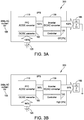
- FIG. 3A is a functional block diagram of another example mode of operation of the UPS 200.
- FIG. 3A shows the UPS 200 running in a backup power source mode of operation, receiving no power from the AC power source 155. Rather, the UPS 200 receives 100% of the power for the load from the backup power source 125.
- the UPS 200 receives DC power from the backup power source 125 at the DC/DC converter 160.
- the DC/DC converter 160 converts the power and provides the power to the inverter 130.
- the UPS 200 is running with the adaptive inverter regulation turned off, the inverter 130 converts the DC power to AC power and provides a full 100% voltage to the load 165.
- the backup power source 125 As the backup power source 125 provides power to the load 165 and depletes, the backup power source will have a specific runtime before the backup power source 125 runs out of power.
- the specific runtime will depend on the amount of power initially stored in the backup power source 125, as well as the amount of power drawn by the load 165.
- FIG. 3B is a functional block diagram of another example mode of operation of the UPS 200.
- FIG. 3B shows the UPS 200 running in the backup power source mode of operation as in FIG. 3A , but with the adaptive inverter regulation set to "high.”
- a "high" setting results in a 6% decrease in output voltage.
- such a decrease in output voltage does not compromise safe operation of the load 165.
- such a decrease can result in a corresponding decrease in current drawn by the load 165.
- the 6% decrease in output voltage can result in a 6% decrease in current drawn by the load 165, so that the runtime of the backup power source 125 can increase by 12% or more.
- the UPS 200 can generate a profile of the load 165 to determine the increase in runtime of the backup power source 125 that would correspond to each of the settings of the adaptive inverter regulation.
- the UPS 200 can generate the load profile by outputting a nominal voltage to the load 165.
- the UPS 100 can then change the voltage output to the load 165 by a known amount, and then measure the change in current produced by such a change in voltage.
- the load profile can provide information related to whether the load 165 is active or passive or a mix of both.
- the load profile can also be used to calculate the battery runtime based on the adjustments made to the inverter 130 and the output voltage.
- the profile of the load 165 can also be used to configure each of the selection settings.
- the UPS 200 can determine a maximum safe reduction of RMS input voltage to the load 165 and change the percentage adjustment of each of the selection settings based on the maximum safe reduction.
- the UPS 200 can set the "high" setting to be half the maximum safe reduction and scale the other settings accordingly. For instance, if the load 165 can safely receive an RMS voltage of 10% less, the UPS 200 can set the "high” setting for the adaptive inverter regulation to be 5%, and correspondingly, the "medium” setting to be 3% and the "low” setting to be 1.5%.
- Other appropriate algorithms can be used to set the selection settings, such as having a minimum percentage for the "low” setting or other such factors.
- the percentages of the settings can be configured by the user, either by manually entering the settings in the UPS or from a remote computer over a network interface of the UPS 200.
- the profile of the load 165 can be affected by an output current limit set on the UPS 200.
- the load 165 includes active load components, reducing the output voltage of the UPS 200 can result in an increase in current drawn by the load 165.
- the UPS 200 can generate a load profile that takes the output current limit into consideration and/or configure the percentages of the selection settings of the adaptive inverter regulation to maximize runtime of the backup power source 125 without exceeding the UPS output current limit.
- the load profile can be used to determine that the increase in runtime of the backup power source 125 is below a threshold. For example, if the load 165 includes primarily active load components, the increase in runtime of the backup power source 125 by decreasing the output voltage can be minimal.
- a threshold such as 1%, can be used to compare the expected runtime increase. If the expected runtime increase does not meet the threshold, in some embodiments, the UPS 100 can suspend the adaptive inverter regulation.
- the backup power source 125 can be replaced with a smaller backup power source, such as a smaller battery. For example, if a threshold amount of runtime is desired for the load 165 from the backup power source 125, if the expected runtime is extended enough based on the load profile, a smaller battery can be used that still meets the threshold amount of runtime, allowing the UPS 200 to utilize less space and/or cost less.
- FIG. 4 is a flow chart of an example process 400 of the UPS 200.
- the process starts.
- the UPS 100 determines whether the adaptive inverter regulation is active.
- the adaptive inverter regulation can be inactive for various reasons, such as the selection setting set to "off," or from expected runtime increases not meeting a threshold, as described earlier. If the adaptive inverter regulation is inactive, the process 400 can exit at act 420. If the adaptive inverter regulation is active, the UPS 200 determines whether the UPS 200 is running in battery operation at act 406.
- the battery operation can include any mode of operation of the UPS 200 where power is drawn from the backup power source 125, whether power is also being received from the AC power source 155 or not.
- the process 400 exits at act 420. If the UPS 200 is running in battery operation, the UPS 100 determines whether a load profile has been performed at act 408. If the load profile has not been performed, the UPS 200 generates a load profile at act 410.
- the load profile can be generated as described above to determine expected battery runtime increases as well as to determine percentage decreases in output voltage for each of the selection settings.
- the UPS 100 can determine whether the load 165 coupled to the UPS 200 has changed by more than a threshold amount. For example, if the threshold amount is 10%, the UPS 200 can determine whether a capacity of the load 165 has changed by 10% or more. If the load 165 has changed by more than the threshold amount, the UPS 200 can reset the load profile and profile the load again.
- a threshold amount is 10%
- the UPS 200 can determine whether a capacity of the load 165 has changed by 10% or more. If the load 165 has changed by more than the threshold amount, the UPS 200 can reset the load profile and profile the load again.
- the UPS 200 receives the selection of the adaptive inverter regulation setting at act 416. Based on the selection of the setting and the profile of the load, the UPS 200 adjusts the output RMS voltage of the inverter 130 at act 418, as described above. At act 420, the process 400 exits.
- UPS's in accordance with embodiments may operate as single phase or multiple phase devices and at a variety of voltage levels.
Claims (13)
- Eine unterbrechungsfreie Stromversorgung (100), die Folgendes beinhaltet:einen ersten Eingang, der konfiguriert ist, um von einer ersten Leistungsquelle Eingangsleistung zu erhalten;einen zweiten Eingang, der konfiguriert ist, um von einer zweiten Leistungsquelle Eingangsleistung zu erhalten;einen Ausgang, der konfiguriert ist, um einer Last Ausgangsleistung bereitzustellen, die von Leistung von mindestens einer von der ersten Leistungsquelle und der zweiten Leistungsquelle stammt;eine Stromrichtschaltung, die mit dem ersten Eingang, dem zweiten Eingang und dem Ausgang gekoppelt ist; undeine Steuerung (120), die mit der Stromrichtschaltung gekoppelt ist, wobei die Steuerung für Folgendes konfiguriert ist:in einem ersten Betriebsmodus, Steuern der Stromrichtschaltung zum Bereitstellen einer Ausgangsspannung der Ausgangsleistung mit im Wesentlichen einem ersten Spannungsniveau;Erzeugen eines Profils der Last;in einem zweiten Betriebsmodus, Steuern der Stromrichtschaltung zum Bereitstellen einer Ausgangsspannung der Ausgangsleistung mit im Wesentlichen einem zweiten Spannungsniveau, wobei das zweite Spannungsniveau niedriger als das erste Spannungsniveau ist und auf dem Profil der Last basiert;Detektieren, dass sich eine Kapazität der Last um einen Schwellenwert geändert hat; undals Reaktion auf die Detektion, Erzeugen eines aktualisierten Profils der geänderten Last.
- Unterbrechungsfreie Stromversorgung gemäß Anspruch 1, wobei die Steuerung (120) konfiguriert ist, um in dem zweiten Betriebsmodus an dem Ausgang Leistung bereitzustellen, die von der zweiten Leistungsquelle stammt.
- Unterbrechungsfreie Stromversorgung gemäß Anspruch 2, wobei die Steuerung (120) konfiguriert ist, um in dem ersten Betriebsmodus an dem Ausgang Leistung bereitzustellen, die ausschließlich von der ersten Leistungsquelle stammt.
- Unterbrechungsfreie Stromversorgung gemäß Anspruch 1, wobei die Steuerung (120) konfiguriert ist, um das Profil der Last durch Folgendes zu erzeugen:Ausgeben einer Nennspannung an die Last;Ändern der Nennspannung um einen bekannten Betrag; undDetektieren einer Änderung des von der Last aufgenommenen Stroms.
- Unterbrechungsfreie Stromversorgung gemäß Anspruch 1, wobei die zweite Leistungsquelle eine Batterie ist und wobei die unterbrechungsfreie Stromversorgung die Batterie umfasst.
- Unterbrechungsfreie Stromversorgung gemäß Anspruch 1, wobei die Steuerung (120) ferner konfiguriert ist, um die zweite Spannung auf der Basis des aktualisierten Profils zu modifizieren.
- Ein Verfahren zum Steuern einer unterbrechungsfreien Stromversorgung (100) mit einem ersten Eingang, der konfiguriert ist, um von einer ersten Leistungsquelle Eingangsleistung zu erhalten, einem zweiten Eingang, der konfiguriert ist, um von einer zweiten Leistungsquelle Eingangsleistung zu erhalten, einem Ausgang, der konfiguriert ist, um einer Last Ausgangsleistung bereitzustellen, die von Leistung von mindestens einer von der ersten Leistungsquelle und der zweiten Leistungsquelle stammt, wobei das Verfahren Folgendes beinhaltet:in einem ersten Betriebsmodus, Steuern der unterbrechungsfreien Stromversorgung zum Bereitstellen einer Ausgangsspannung der Ausgangsleistung mit im Wesentlichen einem ersten Spannungsniveau;Erzeugen eines Profils der Last;in einem zweiten Betriebsmodus, Steuern der unterbrechungsfreien Stromversorgung zum Bereitstellen einer Ausgangsspannung mit im Wesentlichen einem zweiten Spannungsniveau, wobei das zweite Spannungsniveau niedriger als das erste Spannungsniveau ist;Festsetzen des zweiten Spannungsniveaus auf der Basis des erzeugten Profils;Detektieren, dass sich eine Kapazität der Last um einen Schwellenwert geändert hat; undals Reaktion auf die Detektion, Erzeugen eines aktualisierten Profils der geänderten Last.
- Verfahren gemäß Anspruch 7, das ferner in dem zweiten Betriebsmodus das Bereitstellen von Leistung an dem Ausgang beinhaltet, die von der zweiten Leistungsquelle stammt.
- Verfahren gemäß Anspruch 7, wobei das Erzeugen eines Profils Folgendes umfasst:Ausgeben einer Nennspannung an die Last;Ändern der Nennspannung um einen bekannten Betrag; undDetektieren einer Änderung des von der Last aufgenommenen Stroms.
- Verfahren gemäß Anspruch 7, wobei die zweite Leistungsquelle eine Batterie ist und wobei das Verfahren ferner in dem zweiten Betriebsmodus das ausschließliche Bereitstellen von Leistung von der Batterie für die Last umfasst.
- Verfahren gemäß Anspruch 9, das ferner das Modifizieren der zweiten Spannung auf der Basis des aktualisierten Profils beinhaltet.
- Unterbrechungsfreie Stromversorgung (100) gemäß Anspruch 1, wobei der Ausgang konfiguriert ist, um der Last Wechselstromausgangsleistung bereitzustellen.
- Verfahren gemäß Anspruch 7, wobei das Steuern der unterbrechungsfreien Stromversorgung (100) zum Bereitstellen der Ausgangsspannung mit dem ersten und zweiten Spannungsniveau ferner das Bereitstellen von Wechselstromausgangsspannungen mit dem ersten und zweiten Spannungsniveau involviert.
Applications Claiming Priority (1)
| Application Number | Priority Date | Filing Date | Title |
|---|---|---|---|
| PCT/US2013/070039 WO2015072999A1 (en) | 2013-11-14 | 2013-11-14 | Uninterruptible power supply control |
Publications (3)
| Publication Number | Publication Date |
|---|---|
| EP3069431A1 EP3069431A1 (de) | 2016-09-21 |
| EP3069431A4 EP3069431A4 (de) | 2017-08-02 |
| EP3069431B1 true EP3069431B1 (de) | 2019-07-17 |
Family
ID=53057782
Family Applications (1)
| Application Number | Title | Priority Date | Filing Date |
|---|---|---|---|
| EP13897382.1A Active EP3069431B1 (de) | 2013-11-14 | 2013-11-14 | Steuerung für eine ununterbrochene stromversorgung |
Country Status (5)
| Country | Link |
|---|---|
| US (1) | US9882423B2 (de) |
| EP (1) | EP3069431B1 (de) |
| CN (1) | CN105723588B (de) |
| DK (1) | DK3069431T3 (de) |
| WO (1) | WO2015072999A1 (de) |
Families Citing this family (10)
| Publication number | Priority date | Publication date | Assignee | Title |
|---|---|---|---|---|
| JP6418239B2 (ja) * | 2014-06-03 | 2018-11-07 | 株式会社村田製作所 | 電力供給装置および電力供給方法 |
| DE102015104654B3 (de) * | 2014-10-20 | 2016-02-04 | Fujitsu Technology Solutions Intellectual Property Gmbh | Energieversorgungsanordnung und deren Verwendung |
| US9769948B2 (en) * | 2014-12-10 | 2017-09-19 | Eaton Corporation | Modular uninterruptible power supply apparatus and methods of operating same |
| US20160202749A1 (en) * | 2015-01-13 | 2016-07-14 | Netlist, Inc. | System and method for determining charge of a secondary power supply for a memory system |
| US20190067986A1 (en) * | 2017-08-25 | 2019-02-28 | Saudi Arabian Oil Company | Distributed Energy Storage Systems |
| US11258295B2 (en) | 2019-06-10 | 2022-02-22 | C&C Power, Inc. | Maintenance bypass assembly for uninterruptable power supply |
| US11223228B2 (en) * | 2019-06-20 | 2022-01-11 | Schneider Electric It Corporation | Artificially intelligent uninterruptible power supply |
| US11349335B2 (en) * | 2019-11-25 | 2022-05-31 | Cyber Power Systems, Inc. | Power supplying device |
| DE102020101438A1 (de) * | 2020-01-22 | 2021-07-22 | Connaught Electronics Ltd. | Elektronische Recheneinrichtung für ein Kraftfahrzeug mit einer Schaltung, die über eine Steuereinrichtung außerhalb der Recheneinrichtung mit einer Spannung versorgt wird, Anordnung sowie Verfahren |
| US11888340B2 (en) | 2020-12-04 | 2024-01-30 | Schneider Electric It Corporation | Method to enhance the life of a lithium battery |
Family Cites Families (30)
| Publication number | Priority date | Publication date | Assignee | Title |
|---|---|---|---|---|
| US5315533A (en) * | 1991-05-17 | 1994-05-24 | Best Power Technology, Inc. | Back-up uninterruptible power system |
| JPH08154347A (ja) | 1994-11-25 | 1996-06-11 | Japan Storage Battery Co Ltd | 交流無停電電源装置 |
| US5612580A (en) | 1995-10-10 | 1997-03-18 | Northrop Grumman Corporation | Uninterruptible power system |
| US5982652A (en) | 1998-07-14 | 1999-11-09 | American Power Conversion | Method and apparatus for providing uninterruptible power using a power controller and a redundant power controller |
| US6191500B1 (en) * | 1998-11-06 | 2001-02-20 | Kling Lindquist Partnership, Inc. | System and method for providing an uninterruptible power supply to a critical load |
| US6268665B1 (en) * | 1999-05-10 | 2001-07-31 | Mutipower, Inc. | Testing battery power source of uninterruptible power supply |
| US6630752B2 (en) * | 2001-09-12 | 2003-10-07 | Qualmag, Inc. | Uninterruptible transfer switch |
| US7259477B2 (en) | 2003-08-15 | 2007-08-21 | American Power Conversion Corporation | Uninterruptible power supply |
| US6906435B1 (en) * | 2003-12-02 | 2005-06-14 | Handsun Electronic Enterprise Co., Ltd. | Uninterruptible power system with two current conversion units |
| US7446433B2 (en) | 2004-01-23 | 2008-11-04 | American Power Conversion Corporation | Methods and apparatus for providing uninterruptible power |
| US7432615B2 (en) * | 2004-01-29 | 2008-10-07 | American Power Conversion Corporation | Uninterruptable power supply system and method |
| US7050312B2 (en) | 2004-03-09 | 2006-05-23 | Eaton Power Quality Corporation | Multi-mode uninterruptible power supplies and methods of operation thereof |
| US7737580B2 (en) * | 2004-08-31 | 2010-06-15 | American Power Conversion Corporation | Method and apparatus for providing uninterruptible power |
| US7456518B2 (en) * | 2004-08-31 | 2008-11-25 | American Power Conversion Corporation | Method and apparatus for providing uninterruptible power |
| US20060072283A1 (en) * | 2004-09-27 | 2006-04-06 | Thompson James G | Uninterruptible power supply with integral applications processor |
| US7705489B2 (en) * | 2006-09-08 | 2010-04-27 | American Power Conversion Corporation | Method and apparatus for providing uninterruptible power |
| US8212401B2 (en) * | 2007-08-03 | 2012-07-03 | Stratascale, Inc. | Redundant isolation and bypass of critical power equipment |
| NO20083371A (no) * | 2008-08-01 | 2009-10-05 | Therm Tech As | Batterilader og strømforsyning som benytter alternativ energi. |
| GB0818174D0 (en) * | 2008-10-03 | 2008-11-12 | Leaneco Aps | Emergency power supply apparatus |
| JP5171567B2 (ja) * | 2008-11-18 | 2013-03-27 | 株式会社日立製作所 | 無停電電源装置 |
| US20100280676A1 (en) * | 2009-04-30 | 2010-11-04 | Pabon Gus Charles | Multi-functional Bi-directional Communication and Bias Power Architecture for Power Supply Control |
| US9148083B2 (en) | 2009-06-11 | 2015-09-29 | Eaton Corporation | System and method of dynamic regulation of real power to a load |
| US8232760B2 (en) * | 2009-06-11 | 2012-07-31 | Easton Corporation | System and method of dynamic regulation of real power to a load |
| US8203236B2 (en) * | 2009-11-18 | 2012-06-19 | GM Global Technology Operations LLC | Dual voltage-source inverter system and method |
| JP2011135708A (ja) | 2009-12-25 | 2011-07-07 | Hitachi Ltd | 電源システム |
| US8374012B2 (en) * | 2010-06-10 | 2013-02-12 | Carefusion 303, Inc. | Phase-controlled uninterruptible power supply |
| US8803361B2 (en) * | 2011-01-19 | 2014-08-12 | Schneider Electric It Corporation | Apparatus and method for providing uninterruptible power |
| US9362781B2 (en) * | 2012-09-14 | 2016-06-07 | Chloride Srl | Uninterruptible power supply system with fast transfer for undervoltage source line failures |
| US20140197689A1 (en) * | 2013-01-14 | 2014-07-17 | Zippy Technology Corp. | Power supply providing longer lifespan of battery modules |
| US9634512B1 (en) * | 2013-12-03 | 2017-04-25 | Google Inc. | Battery backup with bi-directional converter |
-
2013
- 2013-11-14 EP EP13897382.1A patent/EP3069431B1/de active Active
- 2013-11-14 WO PCT/US2013/070039 patent/WO2015072999A1/en active Application Filing
- 2013-11-14 US US15/035,644 patent/US9882423B2/en active Active
- 2013-11-14 CN CN201380080926.XA patent/CN105723588B/zh active Active
- 2013-11-14 DK DK13897382.1T patent/DK3069431T3/da active
Non-Patent Citations (1)
| Title |
|---|
| None * |
Also Published As
| Publication number | Publication date |
|---|---|
| WO2015072999A1 (en) | 2015-05-21 |
| DK3069431T3 (da) | 2019-10-07 |
| CN105723588A (zh) | 2016-06-29 |
| US20160276870A1 (en) | 2016-09-22 |
| EP3069431A1 (de) | 2016-09-21 |
| EP3069431A4 (de) | 2017-08-02 |
| CN105723588B (zh) | 2019-04-23 |
| US9882423B2 (en) | 2018-01-30 |
Similar Documents
| Publication | Publication Date | Title |
|---|---|---|
| EP3069431B1 (de) | Steuerung für eine ununterbrochene stromversorgung | |
| CN107888087B (zh) | 包括逻辑电路的电源 | |
| EP2174400B1 (de) | Einstellbares batterieaufladegerät für usv | |
| US9929592B2 (en) | UPS sensitivity of power status parameter adjustment setting method | |
| US10033189B2 (en) | Operation control apparatus for solar power system | |
| US10148123B2 (en) | Uninterruptible power supply control | |
| CN110999012B (zh) | 具有改进的节能模式的多模式不间断电源系统 | |
| US20140167504A1 (en) | Parallel boost voltage power supply with local energy storage | |
| KR20160018266A (ko) | 전력 변환 시스템 및 그의 제어 방법 | |
| US9941738B2 (en) | Dynamic DC link voltage control | |
| JP2015050913A (ja) | 電源制御システム | |
| CN106464002B (zh) | 不间断电源系统及其操作方法 | |
| US11258297B2 (en) | Inverter control strategy for a transient heavy load | |
| JP2018170931A (ja) | 電力変換装置、電力変換システム | |
| JP6289123B2 (ja) | 発電システム | |
| JP2006067673A (ja) | 電源装置 | |
| WO2018179712A1 (ja) | 電力変換装置、電力変換システム | |
| US10923750B2 (en) | DC voltage brownout protection for parallel-connected fuel-cell power plants in islanded mode | |
| AU2008284151B2 (en) | Adjustable battery charger for UPS |
Legal Events
| Date | Code | Title | Description |
|---|---|---|---|
| PUAI | Public reference made under article 153(3) epc to a published international application that has entered the european phase |
Free format text: ORIGINAL CODE: 0009012 |
|
| 17P | Request for examination filed |
Effective date: 20160512 |
|
| AK | Designated contracting states |
Kind code of ref document: A1 Designated state(s): AL AT BE BG CH CY CZ DE DK EE ES FI FR GB GR HR HU IE IS IT LI LT LU LV MC MK MT NL NO PL PT RO RS SE SI SK SM TR |
|
| AX | Request for extension of the european patent |
Extension state: BA ME |
|
| DAX | Request for extension of the european patent (deleted) | ||
| A4 | Supplementary search report drawn up and despatched |
Effective date: 20170703 |
|
| RIC1 | Information provided on ipc code assigned before grant |
Ipc: H02J 9/06 20060101AFI20170627BHEP |
|
| REG | Reference to a national code |
Ref country code: DE Ref legal event code: R079 Ref document number: 602013058059 Country of ref document: DE Free format text: PREVIOUS MAIN CLASS: H02J0009000000 Ipc: H02J0009060000 |
|
| GRAP | Despatch of communication of intention to grant a patent |
Free format text: ORIGINAL CODE: EPIDOSNIGR1 |
|
| STAA | Information on the status of an ep patent application or granted ep patent |
Free format text: STATUS: GRANT OF PATENT IS INTENDED |
|
| RIC1 | Information provided on ipc code assigned before grant |
Ipc: H02J 9/06 20060101AFI20190114BHEP |
|
| INTG | Intention to grant announced |
Effective date: 20190205 |
|
| GRAS | Grant fee paid |
Free format text: ORIGINAL CODE: EPIDOSNIGR3 |
|
| GRAA | (expected) grant |
Free format text: ORIGINAL CODE: 0009210 |
|
| STAA | Information on the status of an ep patent application or granted ep patent |
Free format text: STATUS: THE PATENT HAS BEEN GRANTED |
|
| AK | Designated contracting states |
Kind code of ref document: B1 Designated state(s): AL AT BE BG CH CY CZ DE DK EE ES FI FR GB GR HR HU IE IS IT LI LT LU LV MC MK MT NL NO PL PT RO RS SE SI SK SM TR |
|
| REG | Reference to a national code |
Ref country code: GB Ref legal event code: FG4D |
|
| REG | Reference to a national code |
Ref country code: CH Ref legal event code: EP |
|
| REG | Reference to a national code |
Ref country code: DE Ref legal event code: R096 Ref document number: 602013058059 Country of ref document: DE |
|
| REG | Reference to a national code |
Ref country code: IE Ref legal event code: FG4D |
|
| REG | Reference to a national code |
Ref country code: AT Ref legal event code: REF Ref document number: 1156712 Country of ref document: AT Kind code of ref document: T Effective date: 20190815 |
|
| REG | Reference to a national code |
Ref country code: DK Ref legal event code: T3 Effective date: 20191003 |
|
| REG | Reference to a national code |
Ref country code: NL Ref legal event code: MP Effective date: 20190717 |
|
| REG | Reference to a national code |
Ref country code: LT Ref legal event code: MG4D |
|
| REG | Reference to a national code |
Ref country code: AT Ref legal event code: MK05 Ref document number: 1156712 Country of ref document: AT Kind code of ref document: T Effective date: 20190717 |
|
| PG25 | Lapsed in a contracting state [announced via postgrant information from national office to epo] |
Ref country code: FI Free format text: LAPSE BECAUSE OF FAILURE TO SUBMIT A TRANSLATION OF THE DESCRIPTION OR TO PAY THE FEE WITHIN THE PRESCRIBED TIME-LIMIT Effective date: 20190717 Ref country code: NL Free format text: LAPSE BECAUSE OF FAILURE TO SUBMIT A TRANSLATION OF THE DESCRIPTION OR TO PAY THE FEE WITHIN THE PRESCRIBED TIME-LIMIT Effective date: 20190717 Ref country code: PT Free format text: LAPSE BECAUSE OF FAILURE TO SUBMIT A TRANSLATION OF THE DESCRIPTION OR TO PAY THE FEE WITHIN THE PRESCRIBED TIME-LIMIT Effective date: 20191118 Ref country code: HR Free format text: LAPSE BECAUSE OF FAILURE TO SUBMIT A TRANSLATION OF THE DESCRIPTION OR TO PAY THE FEE WITHIN THE PRESCRIBED TIME-LIMIT Effective date: 20190717 Ref country code: LT Free format text: LAPSE BECAUSE OF FAILURE TO SUBMIT A TRANSLATION OF THE DESCRIPTION OR TO PAY THE FEE WITHIN THE PRESCRIBED TIME-LIMIT Effective date: 20190717 Ref country code: BG Free format text: LAPSE BECAUSE OF FAILURE TO SUBMIT A TRANSLATION OF THE DESCRIPTION OR TO PAY THE FEE WITHIN THE PRESCRIBED TIME-LIMIT Effective date: 20191017 Ref country code: SE Free format text: LAPSE BECAUSE OF FAILURE TO SUBMIT A TRANSLATION OF THE DESCRIPTION OR TO PAY THE FEE WITHIN THE PRESCRIBED TIME-LIMIT Effective date: 20190717 Ref country code: AT Free format text: LAPSE BECAUSE OF FAILURE TO SUBMIT A TRANSLATION OF THE DESCRIPTION OR TO PAY THE FEE WITHIN THE PRESCRIBED TIME-LIMIT Effective date: 20190717 Ref country code: NO Free format text: LAPSE BECAUSE OF FAILURE TO SUBMIT A TRANSLATION OF THE DESCRIPTION OR TO PAY THE FEE WITHIN THE PRESCRIBED TIME-LIMIT Effective date: 20191017 |
|
| PG25 | Lapsed in a contracting state [announced via postgrant information from national office to epo] |
Ref country code: IS Free format text: LAPSE BECAUSE OF FAILURE TO SUBMIT A TRANSLATION OF THE DESCRIPTION OR TO PAY THE FEE WITHIN THE PRESCRIBED TIME-LIMIT Effective date: 20191117 Ref country code: AL Free format text: LAPSE BECAUSE OF FAILURE TO SUBMIT A TRANSLATION OF THE DESCRIPTION OR TO PAY THE FEE WITHIN THE PRESCRIBED TIME-LIMIT Effective date: 20190717 Ref country code: ES Free format text: LAPSE BECAUSE OF FAILURE TO SUBMIT A TRANSLATION OF THE DESCRIPTION OR TO PAY THE FEE WITHIN THE PRESCRIBED TIME-LIMIT Effective date: 20190717 Ref country code: GR Free format text: LAPSE BECAUSE OF FAILURE TO SUBMIT A TRANSLATION OF THE DESCRIPTION OR TO PAY THE FEE WITHIN THE PRESCRIBED TIME-LIMIT Effective date: 20191018 Ref country code: LV Free format text: LAPSE BECAUSE OF FAILURE TO SUBMIT A TRANSLATION OF THE DESCRIPTION OR TO PAY THE FEE WITHIN THE PRESCRIBED TIME-LIMIT Effective date: 20190717 Ref country code: RS Free format text: LAPSE BECAUSE OF FAILURE TO SUBMIT A TRANSLATION OF THE DESCRIPTION OR TO PAY THE FEE WITHIN THE PRESCRIBED TIME-LIMIT Effective date: 20190717 |
|
| PG25 | Lapsed in a contracting state [announced via postgrant information from national office to epo] |
Ref country code: TR Free format text: LAPSE BECAUSE OF FAILURE TO SUBMIT A TRANSLATION OF THE DESCRIPTION OR TO PAY THE FEE WITHIN THE PRESCRIBED TIME-LIMIT Effective date: 20190717 |
|
| PG25 | Lapsed in a contracting state [announced via postgrant information from national office to epo] |
Ref country code: PL Free format text: LAPSE BECAUSE OF FAILURE TO SUBMIT A TRANSLATION OF THE DESCRIPTION OR TO PAY THE FEE WITHIN THE PRESCRIBED TIME-LIMIT Effective date: 20190717 Ref country code: EE Free format text: LAPSE BECAUSE OF FAILURE TO SUBMIT A TRANSLATION OF THE DESCRIPTION OR TO PAY THE FEE WITHIN THE PRESCRIBED TIME-LIMIT Effective date: 20190717 Ref country code: RO Free format text: LAPSE BECAUSE OF FAILURE TO SUBMIT A TRANSLATION OF THE DESCRIPTION OR TO PAY THE FEE WITHIN THE PRESCRIBED TIME-LIMIT Effective date: 20190717 Ref country code: IT Free format text: LAPSE BECAUSE OF FAILURE TO SUBMIT A TRANSLATION OF THE DESCRIPTION OR TO PAY THE FEE WITHIN THE PRESCRIBED TIME-LIMIT Effective date: 20190717 |
|
| PG25 | Lapsed in a contracting state [announced via postgrant information from national office to epo] |
Ref country code: IS Free format text: LAPSE BECAUSE OF FAILURE TO SUBMIT A TRANSLATION OF THE DESCRIPTION OR TO PAY THE FEE WITHIN THE PRESCRIBED TIME-LIMIT Effective date: 20200224 Ref country code: SM Free format text: LAPSE BECAUSE OF FAILURE TO SUBMIT A TRANSLATION OF THE DESCRIPTION OR TO PAY THE FEE WITHIN THE PRESCRIBED TIME-LIMIT Effective date: 20190717 Ref country code: SK Free format text: LAPSE BECAUSE OF FAILURE TO SUBMIT A TRANSLATION OF THE DESCRIPTION OR TO PAY THE FEE WITHIN THE PRESCRIBED TIME-LIMIT Effective date: 20190717 Ref country code: CZ Free format text: LAPSE BECAUSE OF FAILURE TO SUBMIT A TRANSLATION OF THE DESCRIPTION OR TO PAY THE FEE WITHIN THE PRESCRIBED TIME-LIMIT Effective date: 20190717 |
|
| REG | Reference to a national code |
Ref country code: DE Ref legal event code: R097 Ref document number: 602013058059 Country of ref document: DE |
|
| REG | Reference to a national code |
Ref country code: CH Ref legal event code: PL |
|
| PLBE | No opposition filed within time limit |
Free format text: ORIGINAL CODE: 0009261 |
|
| STAA | Information on the status of an ep patent application or granted ep patent |
Free format text: STATUS: NO OPPOSITION FILED WITHIN TIME LIMIT |
|
| PG2D | Information on lapse in contracting state deleted |
Ref country code: IS |
|
| PG25 | Lapsed in a contracting state [announced via postgrant information from national office to epo] |
Ref country code: MC Free format text: LAPSE BECAUSE OF FAILURE TO SUBMIT A TRANSLATION OF THE DESCRIPTION OR TO PAY THE FEE WITHIN THE PRESCRIBED TIME-LIMIT Effective date: 20190717 Ref country code: CH Free format text: LAPSE BECAUSE OF NON-PAYMENT OF DUE FEES Effective date: 20191130 Ref country code: LI Free format text: LAPSE BECAUSE OF NON-PAYMENT OF DUE FEES Effective date: 20191130 Ref country code: LU Free format text: LAPSE BECAUSE OF NON-PAYMENT OF DUE FEES Effective date: 20191114 |
|
| 26N | No opposition filed |
Effective date: 20200603 |
|
| REG | Reference to a national code |
Ref country code: BE Ref legal event code: MM Effective date: 20191130 |
|
| PG25 | Lapsed in a contracting state [announced via postgrant information from national office to epo] |
Ref country code: SI Free format text: LAPSE BECAUSE OF FAILURE TO SUBMIT A TRANSLATION OF THE DESCRIPTION OR TO PAY THE FEE WITHIN THE PRESCRIBED TIME-LIMIT Effective date: 20190717 |
|
| PG25 | Lapsed in a contracting state [announced via postgrant information from national office to epo] |
Ref country code: IE Free format text: LAPSE BECAUSE OF NON-PAYMENT OF DUE FEES Effective date: 20191114 |
|
| PG25 | Lapsed in a contracting state [announced via postgrant information from national office to epo] |
Ref country code: BE Free format text: LAPSE BECAUSE OF NON-PAYMENT OF DUE FEES Effective date: 20191130 |
|
| PG25 | Lapsed in a contracting state [announced via postgrant information from national office to epo] |
Ref country code: CY Free format text: LAPSE BECAUSE OF FAILURE TO SUBMIT A TRANSLATION OF THE DESCRIPTION OR TO PAY THE FEE WITHIN THE PRESCRIBED TIME-LIMIT Effective date: 20190717 |
|
| PG25 | Lapsed in a contracting state [announced via postgrant information from national office to epo] |
Ref country code: MT Free format text: LAPSE BECAUSE OF FAILURE TO SUBMIT A TRANSLATION OF THE DESCRIPTION OR TO PAY THE FEE WITHIN THE PRESCRIBED TIME-LIMIT Effective date: 20190717 Ref country code: HU Free format text: LAPSE BECAUSE OF FAILURE TO SUBMIT A TRANSLATION OF THE DESCRIPTION OR TO PAY THE FEE WITHIN THE PRESCRIBED TIME-LIMIT; INVALID AB INITIO Effective date: 20131114 |
|
| PG25 | Lapsed in a contracting state [announced via postgrant information from national office to epo] |
Ref country code: MK Free format text: LAPSE BECAUSE OF FAILURE TO SUBMIT A TRANSLATION OF THE DESCRIPTION OR TO PAY THE FEE WITHIN THE PRESCRIBED TIME-LIMIT Effective date: 20190717 |
|
| PGFP | Annual fee paid to national office [announced via postgrant information from national office to epo] |
Ref country code: GB Payment date: 20231121 Year of fee payment: 11 |
|
| PGFP | Annual fee paid to national office [announced via postgrant information from national office to epo] |
Ref country code: FR Payment date: 20231123 Year of fee payment: 11 Ref country code: DK Payment date: 20231123 Year of fee payment: 11 Ref country code: DE Payment date: 20231127 Year of fee payment: 11 |