EP3068941B1 - Heat pump washing apparatus - Google Patents
Heat pump washing apparatus Download PDFInfo
- Publication number
- EP3068941B1 EP3068941B1 EP13789800.3A EP13789800A EP3068941B1 EP 3068941 B1 EP3068941 B1 EP 3068941B1 EP 13789800 A EP13789800 A EP 13789800A EP 3068941 B1 EP3068941 B1 EP 3068941B1
- Authority
- EP
- European Patent Office
- Prior art keywords
- heat exchanger
- refrigerant
- heat
- tank
- module
- Prior art date
- Legal status (The legal status is an assumption and is not a legal conclusion. Google has not performed a legal analysis and makes no representation as to the accuracy of the status listed.)
- Active
Links
Images


Classifications
-
- D—TEXTILES; PAPER
- D06—TREATMENT OF TEXTILES OR THE LIKE; LAUNDERING; FLEXIBLE MATERIALS NOT OTHERWISE PROVIDED FOR
- D06F—LAUNDERING, DRYING, IRONING, PRESSING OR FOLDING TEXTILE ARTICLES
- D06F39/00—Details of washing machines not specific to a single type of machines covered by groups D06F9/00 - D06F27/00
- D06F39/04—Heating arrangements
-
- D—TEXTILES; PAPER
- D06—TREATMENT OF TEXTILES OR THE LIKE; LAUNDERING; FLEXIBLE MATERIALS NOT OTHERWISE PROVIDED FOR
- D06F—LAUNDERING, DRYING, IRONING, PRESSING OR FOLDING TEXTILE ARTICLES
- D06F39/00—Details of washing machines not specific to a single type of machines covered by groups D06F9/00 - D06F27/00
- D06F39/30—Arrangements for energy recovery
-
- D—TEXTILES; PAPER
- D06—TREATMENT OF TEXTILES OR THE LIKE; LAUNDERING; FLEXIBLE MATERIALS NOT OTHERWISE PROVIDED FOR
- D06F—LAUNDERING, DRYING, IRONING, PRESSING OR FOLDING TEXTILE ARTICLES
- D06F58/00—Domestic laundry dryers
- D06F58/20—General details of domestic laundry dryers
- D06F58/206—Heat pump arrangements
-
- D—TEXTILES; PAPER
- D06—TREATMENT OF TEXTILES OR THE LIKE; LAUNDERING; FLEXIBLE MATERIALS NOT OTHERWISE PROVIDED FOR
- D06F—LAUNDERING, DRYING, IRONING, PRESSING OR FOLDING TEXTILE ARTICLES
- D06F58/00—Domestic laundry dryers
- D06F58/20—General details of domestic laundry dryers
- D06F58/24—Condensing arrangements
-
- F—MECHANICAL ENGINEERING; LIGHTING; HEATING; WEAPONS; BLASTING
- F28—HEAT EXCHANGE IN GENERAL
- F28D—HEAT-EXCHANGE APPARATUS, NOT PROVIDED FOR IN ANOTHER SUBCLASS, IN WHICH THE HEAT-EXCHANGE MEDIA DO NOT COME INTO DIRECT CONTACT
- F28D1/00—Heat-exchange apparatus having stationary conduit assemblies for one heat-exchange medium only, the media being in contact with different sides of the conduit wall, in which the other heat-exchange medium is a large body of fluid, e.g. domestic or motor car radiators
- F28D1/02—Heat-exchange apparatus having stationary conduit assemblies for one heat-exchange medium only, the media being in contact with different sides of the conduit wall, in which the other heat-exchange medium is a large body of fluid, e.g. domestic or motor car radiators with heat-exchange conduits immersed in the body of fluid
- F28D1/04—Heat-exchange apparatus having stationary conduit assemblies for one heat-exchange medium only, the media being in contact with different sides of the conduit wall, in which the other heat-exchange medium is a large body of fluid, e.g. domestic or motor car radiators with heat-exchange conduits immersed in the body of fluid with tubular conduits
- F28D1/053—Heat-exchange apparatus having stationary conduit assemblies for one heat-exchange medium only, the media being in contact with different sides of the conduit wall, in which the other heat-exchange medium is a large body of fluid, e.g. domestic or motor car radiators with heat-exchange conduits immersed in the body of fluid with tubular conduits the conduits being straight
- F28D1/0535—Heat-exchange apparatus having stationary conduit assemblies for one heat-exchange medium only, the media being in contact with different sides of the conduit wall, in which the other heat-exchange medium is a large body of fluid, e.g. domestic or motor car radiators with heat-exchange conduits immersed in the body of fluid with tubular conduits the conduits being straight the conduits having a non-circular cross-section
- F28D1/05366—Assemblies of conduits connected to common headers, e.g. core type radiators
- F28D1/05391—Assemblies of conduits connected to common headers, e.g. core type radiators with multiple rows of conduits or with multi-channel conduits combined with a particular flow pattern, e.g. multi-row multi-stage radiators
-
- D—TEXTILES; PAPER
- D06—TREATMENT OF TEXTILES OR THE LIKE; LAUNDERING; FLEXIBLE MATERIALS NOT OTHERWISE PROVIDED FOR
- D06F—LAUNDERING, DRYING, IRONING, PRESSING OR FOLDING TEXTILE ARTICLES
- D06F25/00—Washing machines with receptacles, e.g. perforated, having a rotary movement, e.g. oscillatory movement, the receptacle serving both for washing and for centrifugally separating water from the laundry and having further drying means, e.g. using hot air
-
- D—TEXTILES; PAPER
- D06—TREATMENT OF TEXTILES OR THE LIKE; LAUNDERING; FLEXIBLE MATERIALS NOT OTHERWISE PROVIDED FOR
- D06F—LAUNDERING, DRYING, IRONING, PRESSING OR FOLDING TEXTILE ARTICLES
- D06F39/00—Details of washing machines not specific to a single type of machines covered by groups D06F9/00 - D06F27/00
- D06F39/12—Casings; Tubs
-
- Y—GENERAL TAGGING OF NEW TECHNOLOGICAL DEVELOPMENTS; GENERAL TAGGING OF CROSS-SECTIONAL TECHNOLOGIES SPANNING OVER SEVERAL SECTIONS OF THE IPC; TECHNICAL SUBJECTS COVERED BY FORMER USPC CROSS-REFERENCE ART COLLECTIONS [XRACs] AND DIGESTS
- Y02—TECHNOLOGIES OR APPLICATIONS FOR MITIGATION OR ADAPTATION AGAINST CLIMATE CHANGE
- Y02B—CLIMATE CHANGE MITIGATION TECHNOLOGIES RELATED TO BUILDINGS, e.g. HOUSING, HOUSE APPLIANCES OR RELATED END-USER APPLICATIONS
- Y02B30/00—Energy efficient heating, ventilation or air conditioning [HVAC]
- Y02B30/52—Heat recovery pumps, i.e. heat pump based systems or units able to transfer the thermal energy from one area of the premises or part of the facilities to a different one, improving the overall efficiency
-
- Y—GENERAL TAGGING OF NEW TECHNOLOGICAL DEVELOPMENTS; GENERAL TAGGING OF CROSS-SECTIONAL TECHNOLOGIES SPANNING OVER SEVERAL SECTIONS OF THE IPC; TECHNICAL SUBJECTS COVERED BY FORMER USPC CROSS-REFERENCE ART COLLECTIONS [XRACs] AND DIGESTS
- Y02—TECHNOLOGIES OR APPLICATIONS FOR MITIGATION OR ADAPTATION AGAINST CLIMATE CHANGE
- Y02B—CLIMATE CHANGE MITIGATION TECHNOLOGIES RELATED TO BUILDINGS, e.g. HOUSING, HOUSE APPLIANCES OR RELATED END-USER APPLICATIONS
- Y02B40/00—Technologies aiming at improving the efficiency of home appliances, e.g. induction cooking or efficient technologies for refrigerators, freezers or dish washers
Definitions
- the present invention relates to a washing apparatus for washing goods as, for example, a dish washing machine or a laundry washing machine.
- the washing machine can be a washing machine or a washing-drying machine (i.e. a washing machine which can both wash and dry the goods).
- the present invention relates to a washing apparatus including a heat pump.
- EP 2 096 203 discloses a household washing machine comprising a tub, a heater and a container.
- the container contains waste water (i.e. used process water) of a previous process phase (e.g. washing or rinsing phase).
- the household washing machine also comprises a heat pump system comprising an evaporator thermally coupled to the container, a condenser, a compressor and an expansion valve.
- a heat pump medium (which is also called "refrigerant" in the following description) is pumped from the compressor to the condenser, where liquefaction takes place accompanied by release of heat. The released heat is used to warm process water contained in the tub.
- the medium passes via the expansion valve to the evaporator where the medium evaporates whilst absorbing heat from the waste water contained in the container. From the evaporator the medium runs back to the compressor. At the end of each process phase, the waste water is drained away from the tub into a waste water line via the container wherein the cooled waste water is replaced.
- EP 2 206 824 discloses a household appliance comprising a tub, a thermal storage tank filled with a liquid and a heat pump system for extracting heat from the liquid contained in the tank and supplying the heat to the tub.
- the liquid is cooled down and iced by the cooling heat rejected by the evaporator of the heat pump while the condenser warms up the washing water.
- the cooling power rejected by the evaporator of the heat pump can be stored in a tank containing a liquid. Said liquid (for example water) is cooled down and then frozen.
- the tank of EP 2 206 824 is a closed tank whose content is not changed within the framework of the normal process carried out by the household appliance. It is also stated that a heat exchanger can be provided between a waste water line and the tank in order to transfer heat from the waste water into the liquid tank.
- the closed tank is used in order to avoid contamination of the tank with deposits from waste water from the tub.
- the cooled/iced liquid needs to be regenerated, that is warmed up again towards the starting temperature, in order to be used again for a next, optionally immediately subsequent, process cycle.
- the heat exchanger used in the tank of EP 2 206 824 is of the coil tube type, which are relatively bulky, so that the tank is also bulky. Therefore, the above drawbacks under point ii) are not satisfactorily solved.
- US2011/239696 discloses an evaporator with a cool storage function which includes a plurality of flat refrigerant flow tubes disposed in parallel such that their width direction coincides with an air flow direction and they are spaced from one another. Air-passing clearances are formed between adjacent refrigerant flow tubes. Cool storage material containers filled with a cool storage material are disposed in some of all the air-passing clearances, and each cool storage material container is brazed to the refrigerant flow tubes located on opposite sides thereof.
- Corrugated fins are disposed in the remaining air-passing clearances, and each fin is brazed to the refrigerant flow tubes located on opposite sides thereof.
- Each cool storage material container includes a plurality of convex portions projecting outward from opposite side surfaces thereof, and projecting ends of the convex portions are joined to the corresponding refrigerant flow tubes. This evaporator with a cool storage function can suppress a drop in cooling performance.
- US5048602 shows a heat exchanger which includes a core and a pair of headers, the core including flat tubes and corrugated fins sandwiched between the tubes, the headers having holes in which the end portions of the tubes are inserted, wherein each tube comprises a stop means for ensuring that an adequate length of the tubes become inserted in the headers.
- the heat exchanger comprises an upper collecting pipe, a lower collecting pipe and a plurality of flat pipes arranged between the two collecting pipes, wherein a flow control plate is fixed in the lower collecting pipe and divides the lower collecting pipe into a first cavity and a second cavity; a refrigerant pipe joint is arranged on the wall surface of the first cavity; and the second cavity is communicated with the flat pipes.
- the heat exchanger is characterized in that at least three communicating holes are arranged on the flow control plate and communicate the first cavity with the second cavity; and at least a distance between a communicating hole and the adjacent communicating hole is different from the distances between other adjacent communicating holes.
- the heat exchanger has the following beneficial effects: the uniformity of flow in the parallel flow heat exchanger can be improved under the condition of different refrigerant flow rates, thus improving the heat exchange efficiency; such air-conditioners with refrigerants flowing variably as inverter air-conditioners can have higher energy efficiency; and meanwhile, the heat exchanger is more convenient to install and is stable, and the flow resistance is slightly increased under the condition of realizing better uniform flow.
- a heat exchanger of the heat pump comprises at least one heat exchanger module including a plurality of heat exchange layers being stacked one above the other in a predetermined direction and each heat exchange layer includes a plurality of channels.
- This module is used either to heat or to cool down liquid, preferably water, contained preferably, but not necessarily, in a storage tank.
- the use of the above-mentioned heat exchanger module including a plurality of heat exchange layers having a plurality of channels enables, among others, to improve the efficiency of the cooled/iced liquid regeneration with respect to the solution described by EP 2 206 824 , as well as to improve the reliability of the washing machine and to lengthen its lifetime.
- modules can be used to warm up water in a tank to be used in washing cycles.
- such a solution of a heat pump having the heat exchanger module including a plurality of stacked layers comprises, due to the specific design, a very wide heat exchange surface in a relatively small volume, thus compact heat exchangers can be realized. In this way, occupying the same volume, either a heat pump more efficient than in the prior art can be realized, or a smaller heat pump can be obtained, leaving more free volume inside the washing apparatus for additional components.
- a compact heat exchanger can be housed in compact tank, in the embodiments in which a tank is present.
- the present invention relates to a washing apparatus comprising:
- the washing apparatus comprises:
- the washing apparatus includes a worktop, said worktop including a hollow cavity forming said thermal storage tank.
- the above-mentioned heat exchanger module including a plurality of heat exchange layers having a plurality of channels is advantageously very compact, so as to improve the design and construction of the washing apparatus of the present invention.
- a high ratio between the heat transfer capacity and the heat exchanger volume is achieved: a reduction of the overall dimensions of the heat exchanger is therefore possible, and thus the volume occupied by it within a casing of the washing apparatus can be also reduced.
- the amount of space occupied by the heat exchanger(s) in a basement of the washing apparatus can be much reduced without affecting the amount of exchanged heat, on the contrary the latter quantity is kept substantially constant.
- a significant reduction on the amount of refrigerant needed and of the pressure drop on the refrigerant circuit is obtained.
- the washing apparatus of the invention may include a heat exchanger having the same dimensions as the one of the prior art, but with an increased cooling and/or heating capacity, due to the above mentioned reasons, and therefore improving the energy consumption.
- the heat exchanger module(s) used as first and/or second heat exchanger ensures a proper heat exchange between the refrigerant and the fluid, fluid which is either the washing water or the auxiliary fluid, and limits the space of the assembly consisting of the evaporator and /or the condenser.
- first and/or the second heat exchanger may include more than one heat exchanger module.
- both the first and the second heat exchangers might include the heat exchanger module having a plurality of heat exchanger layers stacked one above the others, or only the first heat exchanger can include such a module, or only the second.
- one of the first or the second heat exchanger may include the heat exchanger module and the other of said first or second heat exchanger may include a "standard" heat exchanger, such as for example a tube in tube heat exchanger.
- the washing apparatus of the invention may include, alternatively or in combination, any of the following characteristics.
- each of said heat exchange layers defines a first and second heat exchange surfaces between a first and a second longitudinally opposite ends and wherein said module includes one layer and an adjacent layer in said predetermined direction, and an empty gap free of any structural element is interposed between said first surface of said layer and said second surface of said adjacent layer.
- the claimed heat exchanger module provides an empty gap free of any further structural element between one layer and an adjacent layer in said predetermined direction, and thus the heat exchanger module lacks fins, or any further structural element, interposed between at least one couple of adjacent layers thereof.
- the layers include each a first and a second surface in which heat transfer takes place.
- the first surface of one layer faces, unless the layer is the first or the last layer in the module, the second surface of an adjacent layer.
- "Adjacent" means the subsequent layer along the stacking direction. The fact that a free gap is present between two adjacent layers means that no structural element is connected to or it is present between the first and the second surfaces of the adjacent layers.
- the longitudinal ends of the layers can be on the other hand connected either to the header(s), such as the inlet and/or outlet header of the module, or to the adjacent layer(s) of the module.
- said heat exchanger module of the evaporator is used as refrigerant-to-water heat exchanger module, i.e. it is used for the heat exchange between the refrigerant and the liquid (for example washing water) contained in the thermal storage tank.
- the liquid in the thermal storage tank is preferably frozen during the heat exchange, while the refrigerant is absorbing heat.
- the heat exchanger module is housed, at least partially, inside the thermal storage tank.
- fins are not present between heat exchange layers of the heat exchanger module.
- heat exchanger modules provided with fins are not preferred to be used in this embodiment in the present invention, because damages or breakings could occur at the contact points between the layers and the fins due to icing of the liquid contained in the thermal storage tank during heat pump functioning.
- a heat exchanger layers having a plurality of fins properly spaced between the layers can be envisaged as well. Fins having a wide enough pitch, for example, could also prevent damage during freezing.
- the washing apparatus comprises
- the condenser includes the heat exchanger module having a plurality of stacked heat exchanger layers. This condenser is used to warm up water in a washing water tank to be used in the washing cycles.
- the heat exchanger module is housed, at least partially, inside the washing water tank.
- fins are not present between heat exchange layers of the heat exchanger module.
- the absence of fins or any further structural element in the heat exchanger module prevents that the first heat exchanger (i.e. the condenser) is clogged with lint or dirt which is inevitably present in the washing water which from the washing water tank flows to the chamber and possibly also vice-versa.
- the first heat exchanger i.e. the condenser
- said channels of each heat exchange layer are arranged one parallel to the others.
- said heat exchange layers of said module are arranged one parallel to the others.
- said heat exchange layers of said module are spaced apart by a same predetermined first distance.
- said predetermined first distance is lower than 20 mm, more preferably lower than 5 mm.
- a short distance between heat exchange layers allows having, in the volume occupied by the module, the insertion of many heat exchange layers and thus the achievement of a relatively wide heat exchange surface.
- said second heat exchanger is thermally coupled to said thermal storage tank, more preferably said heat exchanger module of said second heat exchanger is at least partially arranged in said thermal storage tank.
- said first heat exchanger is thermally coupled to said washing water tank, more preferably said heat exchanger module of said first heat exchanger is at least partially arranged in said washing water tank.
- the presence of the heat exchanger module of the first and/or the second heat exchanger within the tank, either the washing water tank and/or the thermal storage tank, allows obtaining the most efficient heat exchange between refrigerant and fluid present in the tank, due to the direct contact between the heat exchange layers and the fluid (water or other liquid) with which heat exchange takes place.
- the heat exchange layers are located within tank (either thermal storage or washing water tank), and the headers can be located outside the tank itself.
- the heat exchanger module is not located, not even partially, inside the tank (either thermal storage or washing water tank), but it is located adjacent or in contact to one of the tank's walls, so as thermal coupling between the heat exchanger module and the tank is present.
- both said first and said second heat exchangers include at least one of said heat exchanger module.
- the heat pump includes the first and the second heat exchangers both including a heat exchanger module (or more than one) having a plurality of stacked heat exchange layers.
- said second heat exchanger is adapted to heat said refrigerant and to cool a process air blown in an auxiliary circuit, said auxiliary circuit including a fan to move said process air.
- the evaporator thus, including the heat exchanger module, might in this preferred embodiment be a refrigerant-to-air heat exchanger, cooling the refrigerant thanks to process air blown by a fan present in the auxiliary circuit.
- the auxiliary circuit could be either a recirculating circuit for the air, or a duct or passage within the casing of the washing apparatus.
- the inlet and the outlet of such a circuit are for examples apertures in the casing.
- the washing apparatus includes
- both first and second heat exchangers are refrigerant-to-liquid heat exchangers including the heat exchanger module. The efficiency of the heat pump is thus increased.
- the washing apparatus further comprises a water outlet circuit for discharging waste water from the chamber.
- the thermal storage tank is fluidly connected to water mains by means of a conduit configured so as to supply tap water from the water mains to the thermal storage tank bypassing said chamber.
- said auxiliary fluid includes tap water.
- the liquid present therein preferably freezes at least partially.
- the frozen liquid needs to be regenerated so that, in the next operation of the washing apparatus, the refrigerant can be warmed up again efficiently absorbing heat from the liquid.
- tap water is introduced inside the tank itself. The introduction of tap water can take places at any moment in time during the washing/rinsing/spinning cycles, being independent from the latter (e.g. the water used for regeneration does not come from the chamber), allowing a great flexibility in the washing apparatus' operations.
- the fluid present in the thermal storage tank is water, preferably tap water that comes into the thermal storage tank via a conduit, which bypasses the chamber.
- a conduit which bypasses the chamber.
- a water outlet to discharge the tap water from the thermal storage tank is present.
- the thermal storage tank is fluidly connected to the chamber by means of a discharge conduit configured so as to supply drain water from the chamber to the tank.
- said auxiliary fluid includes drain water.
- the drain water from the chamber is used.
- the advantage of this configuration is that the drain water, i.e. the water which has been used in the washing cycle(s) to wash the items present in the chamber, is relatively warm and can defrost the liquid in the thermal storage tank rather quickly.
- the regeneration of the liquid in the thermal storage tank in this embodiment can take place only when the washing cycle(s) has ended.
- said thermal storage tank is a closed tank, without auxiliary fluid inlet and/or outlet.
- the thermal storage tank contains a fixed amount of auxiliary fluid which does not change with time, the thermal storage tank being filled during the apparatus fabrication, without additional refilling necessary.
- No auxiliary fluid inlet or auxiliary fluid outlet are present, however a refrigerant inlet and a refrigerant outlet has to be present in case the second heat exchanger is located at least partially inside the thermal storage tank itself.
- a “sealed” or “closed” tank in the present context refers to a tank that does not have fluid inlet or outlet, where with “fluid” the fluid being in contact with the tank's walls is meant.
- refrigerant inlet and/or outlet feeding the heat exchanger can be present, the refrigerant not being in contact with the tank's walls.
- the washing apparatus includes a water circuit fluidly connecting said washing water tank and said chamber, said water circuit being a recirculation circuit to recirculate the water from the chamber to the tank and vice-versa.
- the water heated in the washing water tank by the first heat exchanger is moved to the washing chamber, for example as soon as a certain pre-set temperature of the washing water heated by the first heat exchanger is reached, to be used in the washing cycles.
- the water from the chamber preferably returns to the tank to be heated up again.
- the water circuit is not a recirculation circuit.
- the water is heated up in the washing water tank and introduced in the chamber when a given temperature is reached.
- the tank is afterwards filled up again with tap water.
- the channels have a hydraulic diameter smaller or equal than 5 mm.
- the module of the invention may include many channels, therefore the refrigerant flow is divided in a plurality of smaller refrigerant streams, one per channel. In this way the pressure drop of the refrigerant within the channels is reduced compared to the refrigerant pressure drop in bigger channels.
- the shape of the cross section of the channels is not relevant for the present invention, and it can be squared, rectangular, circular (in this case the hydraulic diameter coincide with the diameter of the circle), elliptic, and so on.
- the cross section of the plurality of channels does not have to be the same for all channels in the plurality, but it can be different and the various channels can have a combination of the possible above listed cross sections.
- the cross section may vary both in hydraulic diameter and/or in shape along the extension of the channel.
- said heat exchange layer includes a plurality of channels one parallel to the others.
- the channels are rectilinear, their longitudinal extension (and longitudinal direction) corresponds to their longitudinal axis.
- their longitudinal extension (and longitudinal direction) corresponds to the line joining the point from which they depart from the inlet/outlet header and the first point having the maximum distance from the inlet/outlet header longitudinal axis.
- the channels may include rectilinear portions and/or bumps or other turbulence-inducing elements that may enhance the heat transfer between the refrigerant and the air process stream. Additionally, channels may include smooth or corrugated inner and/or outer surfaces and may comprise bends or curves.
- said hollow cavity of said worktop also forms said washing water tank.
- the worktop is thus preferably substantially integral with the tank, either the thermal storage or the washing water tank, or both, which is realized as a hollow portion of the worktop. More preferably, it includes also the heat exchanger housed at least partially in the tank.
- the worktop includes in this way in addition to the top cover of the casing of the washing apparatus, also a portion of the heat pump.
- the heat pump washing apparatus may include preferably a washing machine to wash clothes, or a dish washer.
- the washing machine can mean either a washing machine only or a washing-drying machine.
- Washing apparatus 1 comprises a chamber 10 for treating goods, such as clothes, and advantageously further comprises a water inlet circuit 70 adapted to supply water, that can be optionally mixed with washing products, into the chamber 10.
- the chamber 10 can be a tub which contains a drum rotatably mounted and optionally perforated (not shown).
- the water inlet circuit 70 preferably comprises a detergent dispenser 72 and water inlet pipes 74.
- the water inlet pipes 74 fluidly connect water mains 40 to the chamber 10, preferably via the detergent dispenser 72, while the latter 72 is adapted to be filled with products, for example detergents, softener, bleaching, sparkling/rinse aid substances, etc.
- the detergent dispenser 72 can comprise one or more compartments (not shown) for one or more products from which a certain amount of these products, depending on the washing program, is delivered into the chamber 10.
- the washing apparatus 1 also comprises a water outlet circuit 50 for discharging waste water (i.e. used water optionally mixed with washing products) from the chamber 10 after process cycles (e.g., washing, rinsing cycles).
- waste water i.e. used water optionally mixed with washing products
- the water outlet circuit 50 can comprise a draining pump 51 and outlet draining pipes 52, for example apt to be connected to the sewage system (not shown).
- the water outlet circuit 50 is advantageously fluidly connected to the bottom of the chamber 10.
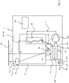
- washing apparatus 1 comprises a heat pump system 20 adapted to heat water to be used in the chamber 10.
- heat pump system has to absorb heat from an auxiliary fluid.
- washing apparatus 1 may include a tank 30' apt to contain the auxiliary fluid from which heat is absorbed, as detailed below and as shown in figure 1a . Heat is absorbed from the auxiliary fluid present in the thermal storage tank, and the fluid can at least partially freeze.
- the auxiliary fluid is not contained in the thermal storage tank 30', but flows in an auxiliary circuit 100.
- the washing apparatus 1 may include a washing water tank 30 (see figure 1a ) apt to be filled with washing water which is - as soon as a given temperature is reached - introduced into the chamber 10 to be used for the washing cycles. Water in the washing water tank 30 is heated up by the heat pump.
- the heat pump system 20 comprises a refrigerant circuit 21, which is a closed recirculating circuit, in which a refrigerant can flow, and which comprises: a first heat exchanger 22 acting as a condenser for cooling the refrigerant and to heat water to be used in the process chamber 10, a second heat exchanger 24 acting as an evaporator for heating the refrigerant and to cool the auxiliary fluid, a compressor 26 arranged in the circuit between the first heat exchanger and the second heat exchanger, and a pressure lowering device 28 arranged between the second heat exchanger and the first heat exchanger.
- a refrigerant circuit 21 which is a closed recirculating circuit, in which a refrigerant can flow
- a first heat exchanger 22 acting as a condenser for cooling the refrigerant and to heat water to be used in the process chamber 10
- a second heat exchanger 24 acting as an evaporator for heating the refrigerant and to cool the auxiliary fluid
- a compressor 26 arranged in the circuit
- the auxiliary fluid cooled by the second heat exchanger could be a fluid flowing in the auxiliary circuit 100.
- the auxiliary circuit 100 preferably is a closed recirculating circuit and preferably the auxiliary fluid is water.
- Auxiliary circuit 100 further preferably includes a pump 101 to force fluid circulation in the circuit.
- the auxiliary circuit 100 is a circuit in which air flows and the auxiliary fluid is process air blown by fan 101.
- the auxiliary circuit 100 can be open having an inlet and an outlet (not depicted in the appended drawings) realized in a casing of the washing apparatus 1.
- the refrigerant is circulated within the circuit 21 by the compressor 26.
- Compressor 26 can be for example a variable speed compressor.
- the pressure lowering device 28 is preferably a controllable valve that operates under the control of a control unit to adapt the flow resistance for the refrigerant in dependency of operating states of the heat pump system 20.
- the pressure lowering device 28 may include a capillary tube, a throttle valve with fixed or variable cross section, etc. (all not shown).
- the refrigerant is pumped from the compressor 26 to the condenser 22, where liquefaction of the refrigerant takes place transferring heat from the refrigerant to the water to be used in the chamber 10.
- This water to be used in the chamber 10 either flows in a water circuit 80, 90 or is contained in a washing water tank 30, as detailed below.
- the condenser 22 is part of a water circuit, better detailed below, so that the water for washing items present in the chamber is warmed up due to the heat exchange with the refrigerant.
- the refrigerant passes via the pressure lowering device 28 to the evaporator 24 where the refrigerant evaporates thus heat is transferred from the auxiliary fluid to the refrigerant. From the evaporator 24, the refrigerant runs back to the compressor 26.
- heat exchange takes place between the refrigerant in the refrigerant circuit 21 and the auxiliary fluid in the auxiliary circuit 100 or in tank 30'.
- auxiliary fluid is a liquid flowing in auxiliary circuit 100
- the auxiliary fluid partially freezes during heat exchange with the refrigerant, which absorbs heat.
- the auxiliary fluid present in the thermal storage tank 30' freezes, at least partially, when heat exchange takes place.
- the flow of refrigerant and the flow of auxiliary fluid are in opposite directions.
- the water to be used in the chamber 10 is preferably made to flow through the condenser 22 so that it exchanges energy with the refrigerant by forced convention.
- the water can be continuously recirculated by a pump through the condenser 22 and back to the chamber 10 until the desired temperature is reached or tap water can be heated directly, by flowing through the condenser 22, before entering into the chamber 10.
- FIG 4 shows an example of the washing machine 1 of figure 1a including a washing water tank 30.
- This embodiment is substantially analogue to the example of figure 1 and thus only the differences will be detailed.
- Washing water tank 30 is located along the refrigerant circuit 21.
- condenser 22 is positioned at least partially within the washing water tank 30, to heat up the water contained in the latter. More preferably, condenser 22 is completely contained in washing water tank 30.
- the condenser 22 is described more in detail below.
- the water to be used in the chamber 10 is preferably made to flow through the washing water tank 30 where condenser 22 is located so that it exchanges heat with the refrigerant by forced convention.
- the water can be continuously recirculated by a pump in a washing circuit 80 through the washing water tank 30 with condenser 22 and back to the chamber 10 until the desired temperature is reached or tap water can be heated directly, by flowing through the condenser 22, before entering into the chamber 10.
- the tank 30 "stores" the heated up water.
- the auxiliary fluid from which heat is absorbed in order to heat up the washing water in washing water tank 30 can be a liquid or air that circulates in the auxiliary circuit 100.
- Washing water circuit 80 in the example of fig. 4 is a recirculating circuit.
- the washing machine 1 comprises a different water circuit 90.
- the water circuit 90 comprises a pump 92 and pipes 94 adapted to directly drain tap water from the water mains 40 bypassing the chamber 10, to conduct the tap water through the washing water tank 30 (not shown in figure 3 ) where the condenser 22 is located and then into the chamber 10, without recirculation.
- the tank 30, heat exchanger 22, and the flow rate of the water should be suitably sized.
- FIG. 1a a different example of the washing machine 1 of fig. 1a is depicted, where a thermal storage tank 30' is included.
- This example is an embodiment of the invention.
- the evaporator 24 of heat pump 20 is housed within the tank 30'.
- the apparatus 1 and heat pump system 20 includes the same characteristics as described in the above embodiment with reference to fig. 1 , 1a and 4 . In the following only the differences between the examples of figs. 1 , 1a and 4 and the embodiments of figs. 2 and 3 will be detailed.
- the chamber 10 is fed with warm water which is heated by condenser 22, and which is flowing into water circuit 80, 90 as described with reference to figs. 1 , 1a and 4 .
- washing water tank 30 might or might not be present and, in the first case, the condenser 22 can be located - at least partially - within the washing water tank 30. Therefore, an embodiment of the present invention includes both the thermal storage tank 30' and the washing water tank 30.
- the washing water tank 30 is used as described in the examples of figs. 1a and 4 .
- only thermal storage tank 30' can be included, without the presence of washing water tank 30.
- the heat produced in the condenser 22 is extracted from the auxiliary fluid by the evaporator 24.
- the evaporator 24 is housed, at least partially, in the thermal storage tank 30' and the auxiliary fluid is the liquid contained in the thermal storage tank 30'.
- the fluid within the tank 30' freezes, at least in part, it needs to be regenerated in order to be used for subsequent washing operations, where heat needs again to be extracted from the liquid present in the thermal storage tank 30'.
- Different regeneration schemes are possible, so that the fluid frozen in the tank 30' can melt in a relatively quick manner.
- Tank 30' is - in a preferred embodiment of the invention - sealed, i.e. there is no input or output for the auxiliary fluid contained therein.
- tank 30' is filled in the factory during the apparatus' production and the auxiliary fluid is not refilled or replaced during the remaining apparatus' useful life.
- This embodiment is shown in fig. 2 .
- the thermal storage tank 30' may include a fluid input 102' which is directly fluidly connected to a water source, such as public water mains 40 in order to be able to directly receive tap water from it.
- the input 102' and the water mains 40 are suitably connected to each other through a tap water conduit 41, which is adapted to supply tap water from the water mains 40 to the tank 30'.
- the tap water conduit 41 bypasses the chamber 10.
- tank 30' includes - in addition to the fluid input 102' to receive the tap water - also preferably a fluid output 103' fluidly connected to the water outlet circuit 50 in order to drain away liquid from the tank 30' via the water outlet circuit 50.
- the output 103' and the water outlet circuit 50 are suitably connected through pipes 34.
- the regeneration takes place due to the drain water contained in the chamber 10 and a conduit connects tank 30' to the chamber 10.
- the drain water used to wash items into chamber 10 is additionally used for the regeneration of the frozen liquid. Its relatively high temperature speeds up the regenerative process.
- the auxiliary fluid contained in the tank 30' advantageously is water.
- the tank 30' containing the evaporator 24 is advantageously positioned on a bottom region of the washing machine 1. However, it can be positioned in any location of the washing apparatus.
- the amount of liquid contained in the thermal storage tank 30' and washing water tank 30, as well as their volume depends on the amount of water that must be heated up during a process cycle of the washing machine 1, the temperature required for the water, the dimensions of heat exchangers 22, 24 possibly housed in the tank 30, 30' and the percentage of frozen liquid in the tank 30'.
- the shape of the tank 30, 30' can be of any type; advantageously it has a box-like shape.
- tank 30, 30' is closed, i.e. it defines a finite inner volume. This means that the tank 30, 30' is surrounded by walls in all directions; however apertures for piping are envisaged.
- Thermal storage tank 30' may include the input and the output 102', 103' for the auxiliary fluid or it can be sealed, e.g. there is no exchange of auxiliary fluid to the outside of the tank 30'. It is to be understood that, in case the evaporator 24 is housed in tank 30', thermal storage tank 30' has to include an input and an output for the flow of refrigerant into the evaporator 22.
- Washing water tank 30 is always including an input and an output for the auxiliary fluid, in this case water, in order to draw and bring water from/to chamber 10, so it cannot be sealed.
- auxiliary fluid in this case water
- suitable input and output piping 30a, 30b for the refrigerant protrude in order to connect the evaporator 24 to the remaining refrigerant circuit 21 outside tank 30'.
- analogue piping for the refrigerant protruding from the washing water tank 30 can be present as well.
- the thermal storage tank 30' can be thermally coupled to the water outlet circuit 50 in order to transfer heat from waste water flowing through the pipes 52 into the liquid contained in the thermal storage tank 30'.
- thermal coupling can be achieved by placing the draining pipes 52 in contact with the tank 30'.
- the tank 30' can be thermally coupled to electronic components and heated elements inside the machine (not shown, as for example compressor, motor, inside air).
- the thermal energy released by these components can be transferred to the liquid in the tank 30' for example by natural convection, forced convection or conduction.
- the washing apparatus 1 suitably comprises a control unit 60 configured to control operation of the washing apparatus 1.
- the first and/or the second heat exchanger 22, 24 includes one or more heat exchanger modules 102.
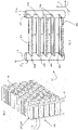
- the structure of a single module 102 will be now described, which may belong to the first and/or second heat exchanger.
- the heat exchanger module 102 includes an inlet header 105 and an outlet header 106.
- Inlet and outlet headers 105, 106 have preferably the structure of a pipe.
- the headers 105, 106 have a longitudinal extension along an axis, which corresponds to the main direction of flow of the refrigerant within the headers.
- the refrigerant is flowing into the module 102 via the inlet header 105 and exiting the same via the outlet header 106.
- a plurality of channels, each indicated with 107, is fluidly connecting the inlet to the outlet header and vice-versa, so that the refrigerant can enter and exit the module. In the plurality of channels 107, the refrigerant flows and heat exchange takes place between the refrigerant and either the washing water to be used in the chamber 10 or the auxiliary fluid.
- the channels 107 due to their configuration, allow a better heat exchange between the refrigerant and the auxiliary fluid or washing water.
- Channel 107 defines a longitudinal direction X along which it extends, which correspond to the longitudinal extension of the heat exchange layer 108.
- each heat exchange layer includes a plurality of channels 107 which are preferably adjacent and parallel to each other. More preferably, each heat exchanger module 102 includes a plurality of heat exchange layers 108, more preferably all layers 108 are stacked one above the other(s) in a stacking direction Z and even more preferably parallel to each other, substantially forming a plurality of parallel rows.
- Each heat exchange layer 108 has a width W (visible in figure 9b ) which depends on the number of channels 107 which are located one adjacent to the other.
- Each heat exchange layer 108 defines a first and a second surface 109a, 109b which extends along a longitudinal direction X and have the width W above described.
- Each couple of adjacent stacked heat exchange layers 108 of a module includes facing surfaces, e.g. the first surface of a layer of the couples faces the second surface of the adjacent layer of the couple.
- the distance between the two layers is preferably identical for all couples of adjacent layers along the stacking direction in a module 102. Preferably such distance is lower than 20 mm, even more preferably lower than 5 mm.
- a free space or gap g is preferably present between each couple of adjacent heat exchange layers.
- the first and the second surfaces 109a, 109b which are facing each other are free from any structural element. No element is not located nor interposed between them.
- the layers 108 are connected to other structural elements, such as the headers, only via their longitudinal opposite ends 108b, 108c.
- a plurality of fins 150 can be located between each couple of adjacent heat exchange layers.
- the width W of the layer 108 defines a direction Y which, together with the longitudinal direction X of channels 107, defines in turn a heat exchange layer plane (X,Y).
- the heat exchange layer plane (X, Y) can be perpendicular to the stacking direction Z or form an angle with the same.
- each heat exchange layer 108 can also be not planar, but for example curved, e.g., having a concavity pointing either up or down along the stacking direction.
- a section of a header 105, 106 is represented.
- the header 105, 106 includes a cylindrical envelope 117 in which a plurality of holes 117a are realized.
- Each hole 117a indicates one of the ends of the channels 107 forming the heat exchange layer 108.
- different configurations are possible.
- the cross section of the headers 105, 106 is circular, as shown in the appended drawings, or oblong.
- the cross section of the header refers to the cross section of the header along a plane perpendicular to the stacking direction Z.
- the oblong cross section is such that its smallest diameter, i.e., the smallest cord passing through the geometrical center of the cross section, is smaller than the width W of the layer 108.
- the refrigerant entering the module 102 via the inlet header 105 can come from the outlet header 106 of another module 102, from the compressor 26 or from the pressure lowering device 28. Additionally, the refrigerant exiting the outlet header 106 may be directed towards the inlet header 105 of another module 102, towards the pressure lowering device 28 or towards the compressor 26.
- the flow of the refrigerant R will be indicated with a dotted line having a pointing arrow in the direction of the flow.
- Each heat exchange layer 108 includes two opposite ends 108b, 108c.
- one end 108b is connected to the inlet header 105 and the opposite end 108c is connected to the outlet header 106.
- an additional intermediate header can be present, as detailed below.
- the ends 108b, 108c of the layer can be connected to the ends of adjacent layer(s) and only the lowermost and/or topmost layers are connected to either the inner or the outlet header.
- the inlet and outlet headers 105,106 are parallel one to the other and extends along the stacking direction Z, and the channels 107 connecting the two headers 105, 106 are substantially straight along the longitudinal direction X.
- Channels 107 form heat exchange layers 108, each of which includes an upper and a lower surfaces 109a, 109b within which the channels 107 are realized.
- a plurality of heat exchange layers 108 connects the inlet 105 to the outlet header 106, all heat exchange layers having a first end 108b and a second end 108c longitudinally opposite to each other, the first end being connected to the inlet header and the second end being connected to the outer header.
- Heat exchange layers are stacked one above the other(s) along the stacking direction Z and each of them forms a plane (X, Y) defined by the longitudinal extension X of the channels 107 and the width W.
- the module 102 is mounted so that the heat exchange layers 108 form planes between which the fluid (either the washing water or the auxiliary fluid) with which heat exchange takes place is present.
- a plurality of apertures 117a is realized; from each aperture 117a a channel 107 departs.
- the so-formed rows of apertures 117a are parallel one to the other and perpendicular to the longitudinal extension Z of the header 105, 106.
- the refrigerant R enters the inlet header 105 of module 102 via an inlet aperture 5in along a flow direction parallel to the longitudinal extension Z of header 105 and branches off into the various channels 107 via apertures 117a.
- the heat exchange layers 108 are "parallel" to each other according to the refrigerant flow direction, which means that in all layers the refrigerant flows in the same direction.
- the flow of the refrigerant is substantially parallel to the flow direction of the refrigerant in the other channels and has the same direction.
- the refrigerant then exits the module 102 via an outlet aperture 6out of outlet header 106.
- the inlet and the outlet headers 105, 106 are stacked in the stacking direction Z one above the other.
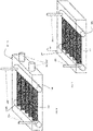
- the inlet and the outlet header 105, 106 are formed by the same pipe or tube, which includes a transverse separator 217 dividing the tube in two separated portions.
- the module 102 of this embodiment thus includes three parallel vertical headers connected by heat exchange layers 108, but two of the headers, the inlet and the outlet headers 105, 106, are realized as a single tube divided in two.
- the third header 105a is an intermediate return header for the refrigerant flow.
- the heat exchange layers 108 are parallel one to the other defining layers' plane (X, Y). Each layer 108 includes two opposite longitudinal ends 108b, 108c, one end being connected to either the inlet or the outlet header 105, 106 and the other end being connected to the intermediate return header 105a. The flow of refrigerant entering the inlet header 105 is therefore prevented by separator 217 to go from the inlet to the outlet header.
- the heat exchange layers 108 are thus divided in two groups: the first group G1 connects the inlet header 105 to the intermediate return header 105a and the second group G2 connects the intermediate header 5a to the outlet header 106.
- the refrigerant R flow which enters the inlet header 105 is distributed via apertures 117a into the first group G1 of heat exchange layers 108 and the refrigerant flows within the parallel channels in the first group G1 towards the intermediate return header 105a. Therefore, the layers 108 within the first group G1 are parallel with respect to the refrigerant flow.
- the refrigerant streams exit the heat exchange layers 108 forming the first group G1 and enter the intermediate return header 105a, where they merge. From the intermediate header 105a, the refrigerant flow then enters the heat exchange layers 108 forming the second group G2, reaching the outlet header 106.
- the heat exchange layers within the second group G2 are parallel to each other with respect to the refrigerant flow.
- the layers of the two groups G1, G2 are in series with respect to the refrigerant flow. Indeed, the refrigerant flows in parallel in all heat exchange layers belonging to the same group, while the refrigerant has to flow through the heat exchange layers of first and the second group in a given order - the layers of the two groups being thus in series.
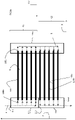
- the module 102 includes only two headers 105, 106, the inlet and the outlet header.
- the module 102 includes only two headers 105, 106, the inlet and the outlet header.
- not all layers are connected to both inlet and outlet headers 105, 106, on the contrary only the first and the last layers are connected to the inlet and the outlet layer, respectively.
- All other layers 108 have their ends 108b, 108c connected to their adjacent layers, e.g. one end to their lower and one end to their upper layer.
- the various layers 108 are substantially formed by a single plurality of cannels bending on themselves several times in order to form the stacked layers.
- Channels layers 108 are parallel to each other.
- the single plurality of channels 107 defines a first rectilinear portion 108e defining the first channels layer connected to the inlet header 105 via one of its ends 108b, it then includes a U-shaped bend 108f and it extends for a second rectilinear portion 108g parallel to the first rectilinear portion 8e defining the second channels layer, and so on, till the last rectilinear portion 108z forming the last layer, which is connected by one of its ends 108c to the outlet header 106.
- a single row of apertures 117a is formed in each header 105, 106 and the flow of refrigerant in the various layers 108 can be considered in series with respect to the refrigerant flow.
- the flows of refrigerant within the various channels 107 forming the channels layers are parallel to each other.
- the module 102 is shown contained inside tank 30, 30'. Although the module 102 is shown completely contained in tank 30, 30', in can also be housed in the latter only partly, for example headers 105, 106 can protrude from the same. Alternatively, the module 102 can be thermally coupled to the tank 30, 30' without being housed in the same, for example tank 30, 30' can be positioned on one (or more) of the external surfaces of the tank's walls.
- FIG. 7 shows thermal storage tank 30' of embodiment depicted in figure 2 .
- the tank 30' is a closed tank, without inlet or outlet for the auxiliary fluid. From tank 30', only an inlet and an outlet 30a, 30b for the refrigerant depart.
- FIG 8 shows either thermal storage tank 30' of the embodiment of figure 3 , or washing water tank 30 of example of figure 4 .
- tank 30, 30' includes an inlet and an outlet 102', 103' for the water and it is thus connected to the water circuit.
- the water circuit is water circuit 80, 90 that connects the washing water tank 30 to the chamber 10 so that the water heated up by condenser 22 in thermal coupling to washing water tank 30 can be introduced into chamber 10.
- Thermal storage tank 30' can be connected either to the mains or to the chamber 10 as far as the inlet 102' is concerned, while the outlet 103' preferably is connected to the discharge outlet circuit 50.
- tank 30' The connection of tank 30' with the mains improves the regeneration of the liquid in the tank 30'.
- either the first or the second heat exchanger 22, 24 includes one or more module 102.
- the condenser 22 could be a standard "tube-in-tube" exchanger, while the evaporator 24 could include module 102 and the auxiliary fluid flowing in the circuit 100 could be air.
- the thermal storage tank 30' or the washing water tank 30, and a heat exchanger 24, 22 is located at least partially into the tank, then the heat exchanger located inside the tank comprises at least one module 102.
- condenser 22 housed in washing water tank 30 includes at least one module 102.
- evaporator 24 housed in thermal storage tank 30' includes at least one module 102.
- both first and second heat exchangers 22, 24 include at least one module 102.
- both first and second heat exchangers 22, 24 include module 102 and both are located, at least partially, inside a respective tank.
- control unit 60 is advantageously configured to switch the heat pump 20 on when water has to be heated into the chamber 10 in order to perform a process cycle (e.g. washing, rinsing, and similar) of the predetermined washing program.
- a process cycle e.g. washing, rinsing, and similar
- the control unit 60 is also advantageously configured to switch the heat pump 20 off when the water in the chamber 10 coming from washing water tank 30 reaches a desired process temperature or when the liquid in the thermal storage tank 30' reaches a predetermined condition (for example, when it is in large part iced).
- tank 30, 30' including module 102 are part of a ready-to-mount element of the washing apparatus 1 called worktop.
- Ready-to-mount element means that the worktop and the tank form an integral element.
- the worktop is a structural part of the apparatus 1 and can be mounted on a casing of the latter simplifying the apparatus' assembly.
- the worktop includes an hollow element in which a heat exchanger 22, 24 can be housed.
- the worktop contains at least part of the heat pump 20. More preferably it contains the first and/or the second heat exchanger 22, 24 and at least part of the refrigerant fluid 21.
- the tank 30, 30' and/or one of the heat exchanger 22, 24 are located on the top of the washing apparatus 1.
Landscapes
- Engineering & Computer Science (AREA)
- Textile Engineering (AREA)
- Physics & Mathematics (AREA)
- Thermal Sciences (AREA)
- Mechanical Engineering (AREA)
- General Engineering & Computer Science (AREA)
- Detail Structures Of Washing Machines And Dryers (AREA)
Priority Applications (1)
| Application Number | Priority Date | Filing Date | Title |
|---|---|---|---|
| PL13789800.3T PL3068941T3 (pl) | 2013-11-13 | 2013-11-13 | Aparat myjący z pompą ciepła |
Applications Claiming Priority (1)
| Application Number | Priority Date | Filing Date | Title |
|---|---|---|---|
| PCT/EP2013/073718 WO2015070900A1 (en) | 2013-11-13 | 2013-11-13 | Heat pump washing apparatus |
Publications (2)
| Publication Number | Publication Date |
|---|---|
| EP3068941A1 EP3068941A1 (en) | 2016-09-21 |
| EP3068941B1 true EP3068941B1 (en) | 2022-04-06 |
Family
ID=49582753
Family Applications (1)
| Application Number | Title | Priority Date | Filing Date |
|---|---|---|---|
| EP13789800.3A Active EP3068941B1 (en) | 2013-11-13 | 2013-11-13 | Heat pump washing apparatus |
Country Status (3)
| Country | Link |
|---|---|
| EP (1) | EP3068941B1 (pl) |
| PL (1) | PL3068941T3 (pl) |
| WO (1) | WO2015070900A1 (pl) |
Families Citing this family (2)
| Publication number | Priority date | Publication date | Assignee | Title |
|---|---|---|---|---|
| ES2672334B1 (es) * | 2016-12-13 | 2019-03-21 | Bsh Electrodomesticos Espana Sa | Máquina lavavajillas doméstica con disposición de bomba de calor |
| CN111603122B (zh) * | 2019-02-25 | 2023-09-01 | 佛山市顺德区美的洗涤电器制造有限公司 | 洗涤电器 |
Citations (3)
| Publication number | Priority date | Publication date | Assignee | Title |
|---|---|---|---|---|
| GB2344643A (en) * | 1998-12-07 | 2000-06-14 | Serck Heat Transfer Limited | Heat exchanger core connection |
| EP2206824A2 (de) * | 2010-02-16 | 2010-07-14 | V-Zug AG | Haushaltgerät mit Bottich, Wärmepumpe und Tank |
| WO2012132924A1 (ja) * | 2011-03-25 | 2012-10-04 | ダイキン工業株式会社 | 熱交換器 |
Family Cites Families (5)
| Publication number | Priority date | Publication date | Assignee | Title |
|---|---|---|---|---|
| US5048602A (en) * | 1989-05-22 | 1991-09-17 | Showa Aluminum Kabushiki Kaisha | Heat exchangers |
| JP5256960B2 (ja) * | 2008-09-22 | 2013-08-07 | パナソニック株式会社 | 物品洗浄乾燥装置 |
| JP5525726B2 (ja) * | 2008-12-26 | 2014-06-18 | 株式会社ケーヒン・サーマル・テクノロジー | 蓄冷機能付きエバポレータ |
| SI2096203T1 (sl) * | 2009-05-28 | 2012-05-31 | V Zug Ag | Gospodinjski pralni stroj s toplotno črpalko |
| CN102230693B (zh) * | 2011-06-28 | 2013-07-31 | 广东美的电器股份有限公司 | 一种换热效率高的平行流换热器 |
-
2013
- 2013-11-13 WO PCT/EP2013/073718 patent/WO2015070900A1/en not_active Ceased
- 2013-11-13 PL PL13789800.3T patent/PL3068941T3/pl unknown
- 2013-11-13 EP EP13789800.3A patent/EP3068941B1/en active Active
Patent Citations (3)
| Publication number | Priority date | Publication date | Assignee | Title |
|---|---|---|---|---|
| GB2344643A (en) * | 1998-12-07 | 2000-06-14 | Serck Heat Transfer Limited | Heat exchanger core connection |
| EP2206824A2 (de) * | 2010-02-16 | 2010-07-14 | V-Zug AG | Haushaltgerät mit Bottich, Wärmepumpe und Tank |
| WO2012132924A1 (ja) * | 2011-03-25 | 2012-10-04 | ダイキン工業株式会社 | 熱交換器 |
Also Published As
| Publication number | Publication date |
|---|---|
| WO2015070900A1 (en) | 2015-05-21 |
| PL3068941T3 (pl) | 2022-08-16 |
| EP3068941A1 (en) | 2016-09-21 |
Similar Documents
| Publication | Publication Date | Title |
|---|---|---|
| EP2978360B1 (en) | Heat pump washing apparatus | |
| EP2959051B1 (en) | Washing machine | |
| EP2749682B1 (en) | Washing-dryer machine | |
| EP2728052B1 (en) | Washing machine | |
| EP3192913B1 (en) | Washer-dryer with a cooling water circuit | |
| CN107110516B (zh) | 空调热泵系统与蒸发式冷却系统 | |
| EP2992131B1 (en) | Heat pump washing apparatus | |
| EP2746454A1 (en) | Washer-dryer machine | |
| EP3068941B1 (en) | Heat pump washing apparatus | |
| CN203096464U (zh) | 干衣机 | |
| EP2992132B1 (en) | Washing machine with heat pump | |
| CN217659729U (zh) | 洗涤设备 | |
| CN102995369A (zh) | 干衣机 | |
| CN215227352U (zh) | 洗涤电器 | |
| CN220520917U (zh) | 衣物处理装置 | |
| CN220376967U (zh) | 衣物处理装置 | |
| KR20110084889A (ko) | 세척 기구 | |
| AU2013405470A1 (en) | Heat pump laundry dryer | |
| CN217659704U (zh) | 洗涤设备 | |
| JP2017099611A (ja) | 衣類乾燥機 | |
| WO2024109449A1 (zh) | 衣物处理装置 | |
| CN117652968A (zh) | 洗碗机、洗碗机的控制方法及装置、可读存储介质 | |
| JPH09203573A (ja) | 製氷器 | |
| CN220520918U (zh) | 衣物处理装置 | |
| CN203247438U (zh) | 干衣机 |
Legal Events
| Date | Code | Title | Description |
|---|---|---|---|
| PUAI | Public reference made under article 153(3) epc to a published international application that has entered the european phase |
Free format text: ORIGINAL CODE: 0009012 |
|
| 17P | Request for examination filed |
Effective date: 20160613 |
|
| AK | Designated contracting states |
Kind code of ref document: A1 Designated state(s): AL AT BE BG CH CY CZ DE DK EE ES FI FR GB GR HR HU IE IS IT LI LT LU LV MC MK MT NL NO PL PT RO RS SE SI SK SM TR |
|
| AX | Request for extension of the european patent |
Extension state: BA ME |
|
| DAX | Request for extension of the european patent (deleted) | ||
| STAA | Information on the status of an ep patent application or granted ep patent |
Free format text: STATUS: EXAMINATION IS IN PROGRESS |
|
| 17Q | First examination report despatched |
Effective date: 20200226 |
|
| REG | Reference to a national code |
Ref country code: DE Ref legal event code: R079 Ref document number: 602013081333 Country of ref document: DE Free format text: PREVIOUS MAIN CLASS: D06F0058200000 Ipc: D06F0039000000 |
|
| GRAP | Despatch of communication of intention to grant a patent |
Free format text: ORIGINAL CODE: EPIDOSNIGR1 |
|
| STAA | Information on the status of an ep patent application or granted ep patent |
Free format text: STATUS: GRANT OF PATENT IS INTENDED |
|
| RIC1 | Information provided on ipc code assigned before grant |
Ipc: F28D 1/053 20060101ALI20211012BHEP Ipc: D06F 39/12 20060101ALI20211012BHEP Ipc: D06F 39/00 20200101AFI20211012BHEP |
|
| INTG | Intention to grant announced |
Effective date: 20211111 |
|
| GRAS | Grant fee paid |
Free format text: ORIGINAL CODE: EPIDOSNIGR3 |
|
| GRAA | (expected) grant |
Free format text: ORIGINAL CODE: 0009210 |
|
| STAA | Information on the status of an ep patent application or granted ep patent |
Free format text: STATUS: THE PATENT HAS BEEN GRANTED |
|
| AK | Designated contracting states |
Kind code of ref document: B1 Designated state(s): AL AT BE BG CH CY CZ DE DK EE ES FI FR GB GR HR HU IE IS IT LI LT LU LV MC MK MT NL NO PL PT RO RS SE SI SK SM TR |
|
| REG | Reference to a national code |
Ref country code: GB Ref legal event code: FG4D |
|
| REG | Reference to a national code |
Ref country code: CH Ref legal event code: EP |
|
| REG | Reference to a national code |
Ref country code: AT Ref legal event code: REF Ref document number: 1481433 Country of ref document: AT Kind code of ref document: T Effective date: 20220415 |
|
| REG | Reference to a national code |
Ref country code: DE Ref legal event code: R096 Ref document number: 602013081333 Country of ref document: DE |
|
| REG | Reference to a national code |
Ref country code: IE Ref legal event code: FG4D |
|
| REG | Reference to a national code |
Ref country code: LT Ref legal event code: MG9D |
|
| REG | Reference to a national code |
Ref country code: NL Ref legal event code: MP Effective date: 20220406 |
|
| REG | Reference to a national code |
Ref country code: AT Ref legal event code: MK05 Ref document number: 1481433 Country of ref document: AT Kind code of ref document: T Effective date: 20220406 |
|
| PG25 | Lapsed in a contracting state [announced via postgrant information from national office to epo] |
Ref country code: NL Free format text: LAPSE BECAUSE OF FAILURE TO SUBMIT A TRANSLATION OF THE DESCRIPTION OR TO PAY THE FEE WITHIN THE PRESCRIBED TIME-LIMIT Effective date: 20220406 |
|
| PG25 | Lapsed in a contracting state [announced via postgrant information from national office to epo] |
Ref country code: SE Free format text: LAPSE BECAUSE OF FAILURE TO SUBMIT A TRANSLATION OF THE DESCRIPTION OR TO PAY THE FEE WITHIN THE PRESCRIBED TIME-LIMIT Effective date: 20220406 Ref country code: PT Free format text: LAPSE BECAUSE OF FAILURE TO SUBMIT A TRANSLATION OF THE DESCRIPTION OR TO PAY THE FEE WITHIN THE PRESCRIBED TIME-LIMIT Effective date: 20220808 Ref country code: NO Free format text: LAPSE BECAUSE OF FAILURE TO SUBMIT A TRANSLATION OF THE DESCRIPTION OR TO PAY THE FEE WITHIN THE PRESCRIBED TIME-LIMIT Effective date: 20220706 Ref country code: LT Free format text: LAPSE BECAUSE OF FAILURE TO SUBMIT A TRANSLATION OF THE DESCRIPTION OR TO PAY THE FEE WITHIN THE PRESCRIBED TIME-LIMIT Effective date: 20220406 Ref country code: HR Free format text: LAPSE BECAUSE OF FAILURE TO SUBMIT A TRANSLATION OF THE DESCRIPTION OR TO PAY THE FEE WITHIN THE PRESCRIBED TIME-LIMIT Effective date: 20220406 Ref country code: GR Free format text: LAPSE BECAUSE OF FAILURE TO SUBMIT A TRANSLATION OF THE DESCRIPTION OR TO PAY THE FEE WITHIN THE PRESCRIBED TIME-LIMIT Effective date: 20220707 Ref country code: FI Free format text: LAPSE BECAUSE OF FAILURE TO SUBMIT A TRANSLATION OF THE DESCRIPTION OR TO PAY THE FEE WITHIN THE PRESCRIBED TIME-LIMIT Effective date: 20220406 Ref country code: ES Free format text: LAPSE BECAUSE OF FAILURE TO SUBMIT A TRANSLATION OF THE DESCRIPTION OR TO PAY THE FEE WITHIN THE PRESCRIBED TIME-LIMIT Effective date: 20220406 Ref country code: BG Free format text: LAPSE BECAUSE OF FAILURE TO SUBMIT A TRANSLATION OF THE DESCRIPTION OR TO PAY THE FEE WITHIN THE PRESCRIBED TIME-LIMIT Effective date: 20220706 Ref country code: AT Free format text: LAPSE BECAUSE OF FAILURE TO SUBMIT A TRANSLATION OF THE DESCRIPTION OR TO PAY THE FEE WITHIN THE PRESCRIBED TIME-LIMIT Effective date: 20220406 |
|
| PG25 | Lapsed in a contracting state [announced via postgrant information from national office to epo] |
Ref country code: RS Free format text: LAPSE BECAUSE OF FAILURE TO SUBMIT A TRANSLATION OF THE DESCRIPTION OR TO PAY THE FEE WITHIN THE PRESCRIBED TIME-LIMIT Effective date: 20220406 Ref country code: LV Free format text: LAPSE BECAUSE OF FAILURE TO SUBMIT A TRANSLATION OF THE DESCRIPTION OR TO PAY THE FEE WITHIN THE PRESCRIBED TIME-LIMIT Effective date: 20220406 Ref country code: IS Free format text: LAPSE BECAUSE OF FAILURE TO SUBMIT A TRANSLATION OF THE DESCRIPTION OR TO PAY THE FEE WITHIN THE PRESCRIBED TIME-LIMIT Effective date: 20220806 |
|
| REG | Reference to a national code |
Ref country code: DE Ref legal event code: R097 Ref document number: 602013081333 Country of ref document: DE |
|
| PG25 | Lapsed in a contracting state [announced via postgrant information from national office to epo] |
Ref country code: SM Free format text: LAPSE BECAUSE OF FAILURE TO SUBMIT A TRANSLATION OF THE DESCRIPTION OR TO PAY THE FEE WITHIN THE PRESCRIBED TIME-LIMIT Effective date: 20220406 Ref country code: SK Free format text: LAPSE BECAUSE OF FAILURE TO SUBMIT A TRANSLATION OF THE DESCRIPTION OR TO PAY THE FEE WITHIN THE PRESCRIBED TIME-LIMIT Effective date: 20220406 Ref country code: RO Free format text: LAPSE BECAUSE OF FAILURE TO SUBMIT A TRANSLATION OF THE DESCRIPTION OR TO PAY THE FEE WITHIN THE PRESCRIBED TIME-LIMIT Effective date: 20220406 Ref country code: EE Free format text: LAPSE BECAUSE OF FAILURE TO SUBMIT A TRANSLATION OF THE DESCRIPTION OR TO PAY THE FEE WITHIN THE PRESCRIBED TIME-LIMIT Effective date: 20220406 Ref country code: DK Free format text: LAPSE BECAUSE OF FAILURE TO SUBMIT A TRANSLATION OF THE DESCRIPTION OR TO PAY THE FEE WITHIN THE PRESCRIBED TIME-LIMIT Effective date: 20220406 Ref country code: CZ Free format text: LAPSE BECAUSE OF FAILURE TO SUBMIT A TRANSLATION OF THE DESCRIPTION OR TO PAY THE FEE WITHIN THE PRESCRIBED TIME-LIMIT Effective date: 20220406 |
|
| PGFP | Annual fee paid to national office [announced via postgrant information from national office to epo] |
Ref country code: FR Payment date: 20221129 Year of fee payment: 10 |
|
| PLBE | No opposition filed within time limit |
Free format text: ORIGINAL CODE: 0009261 |
|
| STAA | Information on the status of an ep patent application or granted ep patent |
Free format text: STATUS: NO OPPOSITION FILED WITHIN TIME LIMIT |
|
| 26N | No opposition filed |
Effective date: 20230110 |
|
| PG25 | Lapsed in a contracting state [announced via postgrant information from national office to epo] |
Ref country code: AL Free format text: LAPSE BECAUSE OF FAILURE TO SUBMIT A TRANSLATION OF THE DESCRIPTION OR TO PAY THE FEE WITHIN THE PRESCRIBED TIME-LIMIT Effective date: 20220406 |
|
| PG25 | Lapsed in a contracting state [announced via postgrant information from national office to epo] |
Ref country code: SI Free format text: LAPSE BECAUSE OF FAILURE TO SUBMIT A TRANSLATION OF THE DESCRIPTION OR TO PAY THE FEE WITHIN THE PRESCRIBED TIME-LIMIT Effective date: 20220406 |
|
| PG25 | Lapsed in a contracting state [announced via postgrant information from national office to epo] |
Ref country code: MC Free format text: LAPSE BECAUSE OF FAILURE TO SUBMIT A TRANSLATION OF THE DESCRIPTION OR TO PAY THE FEE WITHIN THE PRESCRIBED TIME-LIMIT Effective date: 20220406 |
|
| REG | Reference to a national code |
Ref country code: CH Ref legal event code: PL |
|
| REG | Reference to a national code |
Ref country code: BE Ref legal event code: MM Effective date: 20221130 |
|
| PG25 | Lapsed in a contracting state [announced via postgrant information from national office to epo] |
Ref country code: LI Free format text: LAPSE BECAUSE OF NON-PAYMENT OF DUE FEES Effective date: 20221130 Ref country code: CH Free format text: LAPSE BECAUSE OF NON-PAYMENT OF DUE FEES Effective date: 20221130 |
|
| P01 | Opt-out of the competence of the unified patent court (upc) registered |
Effective date: 20230625 |
|
| PG25 | Lapsed in a contracting state [announced via postgrant information from national office to epo] |
Ref country code: LU Free format text: LAPSE BECAUSE OF NON-PAYMENT OF DUE FEES Effective date: 20221113 |
|
| PG25 | Lapsed in a contracting state [announced via postgrant information from national office to epo] |
Ref country code: IE Free format text: LAPSE BECAUSE OF NON-PAYMENT OF DUE FEES Effective date: 20221113 |
|
| PG25 | Lapsed in a contracting state [announced via postgrant information from national office to epo] |
Ref country code: BE Free format text: LAPSE BECAUSE OF NON-PAYMENT OF DUE FEES Effective date: 20221130 |
|
| PG25 | Lapsed in a contracting state [announced via postgrant information from national office to epo] |
Ref country code: HU Free format text: LAPSE BECAUSE OF FAILURE TO SUBMIT A TRANSLATION OF THE DESCRIPTION OR TO PAY THE FEE WITHIN THE PRESCRIBED TIME-LIMIT; INVALID AB INITIO Effective date: 20131113 |
|
| PG25 | Lapsed in a contracting state [announced via postgrant information from national office to epo] |
Ref country code: CY Free format text: LAPSE BECAUSE OF FAILURE TO SUBMIT A TRANSLATION OF THE DESCRIPTION OR TO PAY THE FEE WITHIN THE PRESCRIBED TIME-LIMIT Effective date: 20220406 |
|
| PG25 | Lapsed in a contracting state [announced via postgrant information from national office to epo] |
Ref country code: MK Free format text: LAPSE BECAUSE OF FAILURE TO SUBMIT A TRANSLATION OF THE DESCRIPTION OR TO PAY THE FEE WITHIN THE PRESCRIBED TIME-LIMIT Effective date: 20220406 |
|
| PG25 | Lapsed in a contracting state [announced via postgrant information from national office to epo] |
Ref country code: TR Free format text: LAPSE BECAUSE OF FAILURE TO SUBMIT A TRANSLATION OF THE DESCRIPTION OR TO PAY THE FEE WITHIN THE PRESCRIBED TIME-LIMIT Effective date: 20220406 |
|
| PG25 | Lapsed in a contracting state [announced via postgrant information from national office to epo] |
Ref country code: MT Free format text: LAPSE BECAUSE OF FAILURE TO SUBMIT A TRANSLATION OF THE DESCRIPTION OR TO PAY THE FEE WITHIN THE PRESCRIBED TIME-LIMIT Effective date: 20220406 |
|
| PG25 | Lapsed in a contracting state [announced via postgrant information from national office to epo] |
Ref country code: FR Free format text: LAPSE BECAUSE OF NON-PAYMENT OF DUE FEES Effective date: 20231130 |
|
| PG25 | Lapsed in a contracting state [announced via postgrant information from national office to epo] |
Ref country code: FR Free format text: LAPSE BECAUSE OF NON-PAYMENT OF DUE FEES Effective date: 20231130 |
|
| PG25 | Lapsed in a contracting state [announced via postgrant information from national office to epo] |
Ref country code: BG Free format text: LAPSE BECAUSE OF FAILURE TO SUBMIT A TRANSLATION OF THE DESCRIPTION OR TO PAY THE FEE WITHIN THE PRESCRIBED TIME-LIMIT Effective date: 20220406 |
|
| PG25 | Lapsed in a contracting state [announced via postgrant information from national office to epo] |
Ref country code: BG Free format text: LAPSE BECAUSE OF FAILURE TO SUBMIT A TRANSLATION OF THE DESCRIPTION OR TO PAY THE FEE WITHIN THE PRESCRIBED TIME-LIMIT Effective date: 20220406 |
|
| PGFP | Annual fee paid to national office [announced via postgrant information from national office to epo] |
Ref country code: DE Payment date: 20251126 Year of fee payment: 13 |
|
| PGFP | Annual fee paid to national office [announced via postgrant information from national office to epo] |
Ref country code: GB Payment date: 20251125 Year of fee payment: 13 |
|
| PGFP | Annual fee paid to national office [announced via postgrant information from national office to epo] |
Ref country code: IT Payment date: 20251121 Year of fee payment: 13 |
|
| PGFP | Annual fee paid to national office [announced via postgrant information from national office to epo] |
Ref country code: PL Payment date: 20251103 Year of fee payment: 13 |