EP3068550B1 - Fluid application device having a modular non-contact nozzle for applying fluid to an article - Google Patents
Fluid application device having a modular non-contact nozzle for applying fluid to an article Download PDFInfo
- Publication number
- EP3068550B1 EP3068550B1 EP14805453.9A EP14805453A EP3068550B1 EP 3068550 B1 EP3068550 B1 EP 3068550B1 EP 14805453 A EP14805453 A EP 14805453A EP 3068550 B1 EP3068550 B1 EP 3068550B1
- Authority
- EP
- European Patent Office
- Prior art keywords
- fluid
- strand
- orifice
- application device
- nozzle assembly
- Prior art date
- Legal status (The legal status is an assumption and is not a legal conclusion. Google has not performed a legal analysis and makes no representation as to the accuracy of the status listed.)
- Active
Links
- 239000012530 fluid Substances 0.000 title claims description 170
- 239000000853 adhesive Substances 0.000 claims description 24
- 230000001070 adhesive effect Effects 0.000 claims description 24
- 239000000463 material Substances 0.000 claims description 19
- 238000000034 method Methods 0.000 claims description 14
- 238000007599 discharging Methods 0.000 claims description 4
- 230000004044 response Effects 0.000 claims description 2
- 239000003292 glue Substances 0.000 description 13
- 239000000835 fiber Substances 0.000 description 10
- 239000000047 product Substances 0.000 description 8
- 239000000758 substrate Substances 0.000 description 6
- 230000003068 static effect Effects 0.000 description 3
- 206010021639 Incontinence Diseases 0.000 description 2
- 230000009286 beneficial effect Effects 0.000 description 2
- 239000011248 coating agent Substances 0.000 description 2
- 238000000576 coating method Methods 0.000 description 2
- 238000010586 diagram Methods 0.000 description 2
- 239000013013 elastic material Substances 0.000 description 2
- 238000004519 manufacturing process Methods 0.000 description 2
- 239000004745 nonwoven fabric Substances 0.000 description 2
- 230000008569 process Effects 0.000 description 2
- RNFJDJUURJAICM-UHFFFAOYSA-N 2,2,4,4,6,6-hexaphenoxy-1,3,5-triaza-2$l^{5},4$l^{5},6$l^{5}-triphosphacyclohexa-1,3,5-triene Chemical compound N=1P(OC=2C=CC=CC=2)(OC=2C=CC=CC=2)=NP(OC=2C=CC=CC=2)(OC=2C=CC=CC=2)=NP=1(OC=1C=CC=CC=1)OC1=CC=CC=C1 RNFJDJUURJAICM-UHFFFAOYSA-N 0.000 description 1
- 239000004831 Hot glue Substances 0.000 description 1
- 229920002334 Spandex Polymers 0.000 description 1
- 230000001580 bacterial effect Effects 0.000 description 1
- 230000004888 barrier function Effects 0.000 description 1
- 239000007795 chemical reaction product Substances 0.000 description 1
- 238000004140 cleaning Methods 0.000 description 1
- 230000003247 decreasing effect Effects 0.000 description 1
- 230000000694 effects Effects 0.000 description 1
- 239000004744 fabric Substances 0.000 description 1
- 238000001914 filtration Methods 0.000 description 1
- 239000003063 flame retardant Substances 0.000 description 1
- 230000036541 health Effects 0.000 description 1
- 230000036512 infertility Effects 0.000 description 1
- 230000001788 irregular Effects 0.000 description 1
- 239000007788 liquid Substances 0.000 description 1
- 230000014759 maintenance of location Effects 0.000 description 1
- 239000004759 spandex Substances 0.000 description 1
- 238000001228 spectrum Methods 0.000 description 1
Images


Classifications
-
- B—PERFORMING OPERATIONS; TRANSPORTING
- B05—SPRAYING OR ATOMISING IN GENERAL; APPLYING FLUENT MATERIALS TO SURFACES, IN GENERAL
- B05C—APPARATUS FOR APPLYING FLUENT MATERIALS TO SURFACES, IN GENERAL
- B05C5/00—Apparatus in which liquid or other fluent material is projected, poured or allowed to flow on to the surface of the work
- B05C5/02—Apparatus in which liquid or other fluent material is projected, poured or allowed to flow on to the surface of the work the liquid or other fluent material being discharged through an outlet orifice by pressure, e.g. from an outlet device in contact or almost in contact, with the work
- B05C5/0245—Apparatus in which liquid or other fluent material is projected, poured or allowed to flow on to the surface of the work the liquid or other fluent material being discharged through an outlet orifice by pressure, e.g. from an outlet device in contact or almost in contact, with the work for applying liquid or other fluent material to a moving work of indefinite length, e.g. to a moving web
-
- B—PERFORMING OPERATIONS; TRANSPORTING
- B05—SPRAYING OR ATOMISING IN GENERAL; APPLYING FLUENT MATERIALS TO SURFACES, IN GENERAL
- B05C—APPARATUS FOR APPLYING FLUENT MATERIALS TO SURFACES, IN GENERAL
- B05C5/00—Apparatus in which liquid or other fluent material is projected, poured or allowed to flow on to the surface of the work
- B05C5/02—Apparatus in which liquid or other fluent material is projected, poured or allowed to flow on to the surface of the work the liquid or other fluent material being discharged through an outlet orifice by pressure, e.g. from an outlet device in contact or almost in contact, with the work
- B05C5/0241—Apparatus in which liquid or other fluent material is projected, poured or allowed to flow on to the surface of the work the liquid or other fluent material being discharged through an outlet orifice by pressure, e.g. from an outlet device in contact or almost in contact, with the work for applying liquid or other fluent material to elongated work, e.g. wires, cables, tubes
-
- A—HUMAN NECESSITIES
- A61—MEDICAL OR VETERINARY SCIENCE; HYGIENE
- A61F—FILTERS IMPLANTABLE INTO BLOOD VESSELS; PROSTHESES; DEVICES PROVIDING PATENCY TO, OR PREVENTING COLLAPSING OF, TUBULAR STRUCTURES OF THE BODY, e.g. STENTS; ORTHOPAEDIC, NURSING OR CONTRACEPTIVE DEVICES; FOMENTATION; TREATMENT OR PROTECTION OF EYES OR EARS; BANDAGES, DRESSINGS OR ABSORBENT PADS; FIRST-AID KITS
- A61F13/00—Bandages or dressings; Absorbent pads
- A61F13/15—Absorbent pads, e.g. sanitary towels, swabs or tampons for external or internal application to the body; Supporting or fastening means therefor; Tampon applicators
- A61F13/15577—Apparatus or processes for manufacturing
- A61F13/15585—Apparatus or processes for manufacturing of babies' napkins, e.g. diapers
- A61F13/15593—Apparatus or processes for manufacturing of babies' napkins, e.g. diapers having elastic ribbons fixed thereto; Devices for applying the ribbons
- A61F13/15609—Apparatus or processes for manufacturing of babies' napkins, e.g. diapers having elastic ribbons fixed thereto; Devices for applying the ribbons the ribbons being applied in an irregular path
-
- B—PERFORMING OPERATIONS; TRANSPORTING
- B05—SPRAYING OR ATOMISING IN GENERAL; APPLYING FLUENT MATERIALS TO SURFACES, IN GENERAL
- B05B—SPRAYING APPARATUS; ATOMISING APPARATUS; NOZZLES
- B05B1/00—Nozzles, spray heads or other outlets, with or without auxiliary devices such as valves, heating means
- B05B1/005—Nozzles or other outlets specially adapted for discharging one or more gases
-
- B—PERFORMING OPERATIONS; TRANSPORTING
- B05—SPRAYING OR ATOMISING IN GENERAL; APPLYING FLUENT MATERIALS TO SURFACES, IN GENERAL
- B05C—APPARATUS FOR APPLYING FLUENT MATERIALS TO SURFACES, IN GENERAL
- B05C5/00—Apparatus in which liquid or other fluent material is projected, poured or allowed to flow on to the surface of the work
- B05C5/02—Apparatus in which liquid or other fluent material is projected, poured or allowed to flow on to the surface of the work the liquid or other fluent material being discharged through an outlet orifice by pressure, e.g. from an outlet device in contact or almost in contact, with the work
- B05C5/027—Coating heads with several outlets, e.g. aligned transversally to the moving direction of a web to be coated
-
- B—PERFORMING OPERATIONS; TRANSPORTING
- B05—SPRAYING OR ATOMISING IN GENERAL; APPLYING FLUENT MATERIALS TO SURFACES, IN GENERAL
- B05D—PROCESSES FOR APPLYING FLUENT MATERIALS TO SURFACES, IN GENERAL
- B05D1/00—Processes for applying liquids or other fluent materials
- B05D1/02—Processes for applying liquids or other fluent materials performed by spraying
-
- B—PERFORMING OPERATIONS; TRANSPORTING
- B65—CONVEYING; PACKING; STORING; HANDLING THIN OR FILAMENTARY MATERIAL
- B65H—HANDLING THIN OR FILAMENTARY MATERIAL, e.g. SHEETS, WEBS, CABLES
- B65H57/00—Guides for filamentary materials; Supports therefor
-
- B—PERFORMING OPERATIONS; TRANSPORTING
- B65—CONVEYING; PACKING; STORING; HANDLING THIN OR FILAMENTARY MATERIAL
- B65H—HANDLING THIN OR FILAMENTARY MATERIAL, e.g. SHEETS, WEBS, CABLES
- B65H57/00—Guides for filamentary materials; Supports therefor
- B65H57/04—Guiding surfaces within slots or grooves
-
- B—PERFORMING OPERATIONS; TRANSPORTING
- B65—CONVEYING; PACKING; STORING; HANDLING THIN OR FILAMENTARY MATERIAL
- B65H—HANDLING THIN OR FILAMENTARY MATERIAL, e.g. SHEETS, WEBS, CABLES
- B65H57/00—Guides for filamentary materials; Supports therefor
- B65H57/16—Guides for filamentary materials; Supports therefor formed to maintain a plurality of filaments in spaced relation
-
- B—PERFORMING OPERATIONS; TRANSPORTING
- B05—SPRAYING OR ATOMISING IN GENERAL; APPLYING FLUENT MATERIALS TO SURFACES, IN GENERAL
- B05C—APPARATUS FOR APPLYING FLUENT MATERIALS TO SURFACES, IN GENERAL
- B05C13/00—Means for manipulating or holding work, e.g. for separate articles
-
- B—PERFORMING OPERATIONS; TRANSPORTING
- B65—CONVEYING; PACKING; STORING; HANDLING THIN OR FILAMENTARY MATERIAL
- B65H—HANDLING THIN OR FILAMENTARY MATERIAL, e.g. SHEETS, WEBS, CABLES
- B65H2701/00—Handled material; Storage means
- B65H2701/30—Handled filamentary material
- B65H2701/31—Textiles threads or artificial strands of filaments
Definitions
- the following description relates to a fluid application device having a modular nozzle for applying a fluid to a moving article as defined in the preamble of claim 1, and to a method of applying a fluid with such a fluid application device.
- a fluid application device as defined in the preamble of claim 1 is known from US 2004/164180 A1 .
- US 2002/136833 A1 shows a guide system for supporting and guiding a strand in alignment with a dispensing outlet of a dispenser.
- US2009000545 shows another fluid application device with a guide system for supporting and guiding a strand.
- Nonwoven fabrics are engineering fabrics that provide specific functions such as absorbency, liquid repellence, resilience, stretch, softness, strength, flame retardant protection, easy cleaning, cushioning, filtering, use as a bacterial barrier and sterility.
- nonwoven materials can provide a spectrum of products with diverse properties and can be used alone or as components of hygiene apparel, home furnishings, health care, engineering, industrial and consumer goods.
- a plurality of elasticated strands may be positioned on and bonded to the nonwoven materials to, for example, allow for flexibility fitting around an object or a person.
- the strands may be bonded to the nonwoven fabric with an adhesive in the form of a glue fiber.
- the strands are fed past a nozzle on an adhesive application device.
- the nozzle may include a plurality of outlets through which the glue fiber may be discharged.
- a second fluid, such as air, may be discharged through separate outlets to control the application of the glue fiber such that the glue fiber is vacillated across the respective strands as the strands pass by the nozzle.
- the outlets for discharging air may be positioned on opposite sides of the outlet for discharging the glue fiber, such that there are two air discharge outlets for each glue discharge outlet.
- the strands are spaced approximately 5 -8 millimeters (mm) from respective discharge outlets of the nozzle. That is, the glue fiber is discharged over a gap of approximately 5-8 mm to be applied to the strands.
- a fluid application device having a modular nozzle that may apply a fluid, such as an adhesive, in a non-contacting manner, to a moving article at higher speeds while decreasing overspray.
- a fluid application device as defined in claim 1.
- FIG. 1 is a perspective view of a fluid application device 10 according to an embodiment of the present invention.
- the fluid application device 10 is used to apply a fluid on an article.
- the fluid application device 10 applies a first fluid F1 (see FIG. 2 ) on an article.
- the first fluid F1 may be, for example, an adhesive, and the article may be, for example, an elastic or non-elastic strand 12 of material. That is, in one embodiment, the fluid application device 10 is part of a strand coating system.
- the adhesive may be applied to the strand 12 so that the strand 12 may be adhered to a substrate 14, such as a nonwoven material.
- the strand 12 in one embodiment, may be made from an elastic material and may be in either a stretched condition or a relaxed condition as the first fluid F1 is applied.
- the strand 12 of material may be, for example, spandex, rubber or other similar elastic material.
- the fluid application device 10 includes an applicator head 16.
- the applicator head 16 may include a first fluid supply unit 18, a second fluid supply unit 20 and a nozzle assembly 22.
- the first fluid supply unit 18 is configured to receive the first fluid F1 from a first fluid F1 source (not shown) and the second fluid supply unit 20 is configured to receive a second fluid F2 (shown in FIG. 2 ) from a second fluid source (not shown).
- the nozzle assembly 22 is fluidly coupled to, i.e., is in fluid communication with, the first fluid supply unit 18.
- the nozzle assembly 22 may also be fluidly coupled to, i.e., may be in fluid communication with, the second fluid supply unit 20. Accordingly, the nozzle assembly 22 may receive the first fluid F1 from the first fluid F1 supply unit 18 and the second fluid F2 from the second fluid supply unit 20.
- the applicator head 16 may also include an adapter 24 secured to at least one of the first fluid supply unit 18 and second fluid supply unit 20.
- the adapter 24 is positioned adjacent to the nozzle assembly 22 and is fluidly coupled to, i.e., is in fluid communication with, the nozzle assembly 22.
- the adapter 24 is fluidly coupled to one of or both of the first fluid supply unit 18 and second fluid supply unit 20, such that the nozzle assembly 22 may receive the first fluid F1 and the second fluid F2 via the adapter 24. That is, the adapter 24 is in fluid communication with at least one of the first fluid supply unit 18 and the second fluid supply unit 20 and also the nozzle assembly 22.
- the adapter 24 is configured to have the nozzle assembly 22 secured thereto such that the nozzle assembly 22 may be properly positioned and oriented relative to the applicator head 16 for application of the first fluid F1 onto the strands 12. It is understood that the present disclosure is not limited to this configuration and that the nozzle assembly 22 may be secured to the applicator head 16, adapter 24 or other adjacent component of the applicator head 16.
- the applicator head 16 may also include a flow control module 26.
- the flow control module 26 may include a valve or series of valves to regulate a flow of the first fluid F1 and second fluid F2 from the first fluid supply unit 18 and second fluid supply unit 20, respectively, to the nozzle assembly 22.
- the adapter 24 and flow control module 26 are implemented as the same unit. This unit provides an adhesive path between one of or both of the first and second fluid supply units 18, 20 and the nozzle assembly 22.
- This unit, i.e., the combined adapter 24 and flow control module 26 may also include valving to start and stop the flow of adhesive.
- FIG. 2 is a front view of the nozzle assembly 22 according to an embodiment of the present invention.
- the nozzle assembly 22 includes at least one orifice 28.
- the first fluid F1 is discharged through the orifice 28 to be applied on the strand 12.
- the width of the orifice 28 may vary to accommodate different sizes of strands 12. It is understood that the width of the orifice 28 may refer to a diameter in embodiments where the orifice 28 is circular in shape, or the width measured across a center point of a non-circular shape, such as square or rectangular, in other embodiments.
- the first fluid F1 may be an adhesive, such as a hot melt adhesive.
- the adhesive may be discharged from the orifice 28 as a filament or fiber to be applied on the strand 12.
- the first fluid is discharged over a gap G1 between the orifice 28 and the strand 12.
- the gap G1 may be 0-3 mm, and preferably, 1-2 mm, or in another embodiment, 0-2 mm.
- the first fluid F1 may be discharged from the orifice 28 as a substantially continuous filament or fiber, but may be intermittently discontinuous so long as the first fluid F1 is sufficiently applied to the strand 12 to allow the strand 12 to satisfactorily bond to the substrate 14.
- the applicator head 16 may be heated to either melt the first fluid F1 or maintain the first fluid F1 in a melted condition.
- the first fluid supply unit 18, the second fluid supply unit 20, and/or the nozzle assembly 22 may be heated, and thus, may also radiate heat outwardly.
- the applicator head 16 may also include a heater.
- the nozzle assembly 22 also includes at least one outlet 29 configured to discharge the second fluid F2.
- the second fluid F2 may be, for example, air, and is used to control the application of, or otherwise act on the first fluid to vary a discharge path of the first fluid during application onto the strand 12.
- the second fluid may oscillate the first fluid as it is applied. Accordingly, the first fluid is applied on the strand 12 in a desired pattern.
- each orifice 28 There may be anywhere from one to six air outlets 29 associated with each orifice 28 used to control or alter the discharge of the first fluid F1 from the orifice 28.
- more than one outlet 29 is associated with each orifice 28.
- the outlets 29 and orifices 28 may be positioned along a common plane or line. Alternatively, the outlets may be positioned along a separate line or plane than the orifices 28.
- the second fluid F2 is discharged from the outlets 29 adjacent to each orifice 28 to cause the first fluid F1 to oscillate and be applied to the strand 12 in the desired pattern.
- the first fluid F1 may be applied to the strand 12 in a substantially sinusoidal pattern.
- the present disclosure is not limited to this configuration, and the first fluid F1 may be applied in other patterns.
- the first fluid may be vacillated or oscillated by the second fluid such that the first fluid is applied in, for example, repeated, non-repeated, irregular and/or asymmetrical pattern or patterns.
- the second fluid F2 may be alternately discharged from outlets 29 adjacent to an orifice 28. That is, discharge of the second fluid F2 may be controlled to be started and stopped in an alternating, or partially overlapping manner between the outlets 29, or may be continuously supplied from the outlets 29.
- the first fluid F1 may be continuously or intermittently discharged from the orifice 28.
- a continuous stream of the first fluid F1 may be broken apart by the second fluid F2 such that the first fluid F1 is applied on the strands intermittently.
- FIG. 3 is a perspective view of the fluid application device 10 according to an embodiment of the present invention.
- the fluid application device 10 further includes a strand engagement device 30.
- the strand engagement device 30 may be formed integrally with the applicator head 16.
- the strand engagement device 30 may be secured to the applicator head 16 or other component of the fluid application device 10 with a suitable fastener, including, but not limited to, bolts, screws, rivets, adhesives, welds and the like.
- the strand engagement device 30 is configured to engage the strands 12 and move the strands 12 toward or away from the applicator head 16 and nozzle assembly 22 based on a line condition (active or static) of the fluid application device 10, as discussed further below.
- the nozzle assembly 22 includes a guide plate 32 to assist in positioning of the strands 12 relative to the orifices 28 and outlets of the nozzle assembly 22.
- the guide plate 32 includes at least one guide slot 34 through which the strand 12 is fed.
- the guide slot 34 may be formed in a substantially inverted v-shape, with an open end 36 of guide slot 34 corresponding to a wide portion of the inverted v-shape, and a closed end 38 of the guide slot correspond to a narrow portion of the inverted v-shape.
- the closed end 38 acts as a limit or stop for the strand 12 to position the strand 12 at the desired position relative the orifice 28 and outlets for application of the first fluid F1.
- the closed end 38 acts as a stop to position the strand 12 a predetermined distance, or gap G1, from the orifice 28.
- the strand 12 may either contact the closed end 38 or be positioned in close proximity to the closed end 38.
- the predetermined distance, or gap G1, between the strand 12 and orifice 28 is a distance or gap where overspray may be reduced or minimized.
- the at least one guide slot 34 may be positioned before the orifices 28 of the nozzle assembly 22.
- the at least one guide slot 34 may include three guide slots 34. However, it is understood that the number of guide slots 34 may vary, and is not limited to the example above.
- Each guide slot 34 is associated with a corresponding orifice 28 of the nozzle assembly 22. That is, each guide slot 34 is substantially aligned with a corresponding orifice 28 of the nozzle assembly.
- the closed end 38 of respective guide slots 34 may be aligned with respective orifices 28 in the direction of travel of the strands 12.
- Each guide slot 34 is configured to receive a separate strand 12, although it envisioned that more than one strand 12 may be received in each guide slot 34.
- the nozzle assembly 22 includes a body portion 22a and the guide plate 32 is formed separately from the body portion 22a.
- the guide plate 32 may be formed by a first flange 40 secured to the adapter 24 and a second flange 42 depending from the first flange 40.
- the at least one guide slot 34 may be formed in the second flange 42.
- the guide plate 32 may be secured to the adapter 24 using known fastening techniques, and may be removed, independently of the body portion 22a, for replacement and/or servicing.
- the guide plate 32 may be formed integrally with the body portion 22a of the nozzle assembly 22.
- the guide plate 32 may include a flange that depends from the body portion 22a in which the guide slots 34 are formed.
- the guide plate 32 may be removably secured to the nozzle assembly 22. That is, in one embodiment, the guide plate 32 may be formed integrally with the nozzle assembly 22 by being selectively releasably secured to the body portion 22a of the nozzle assembly 22. For example, the guide plate 32 may be directly secured to the body portion 22a using a known suitable fastener or fasteners. Accordingly, the guide plate 32 may be removed from the nozzle assembly 22, independent of the body portion 22a for replacement or service.
- the strand engagement device 30 includes an engagement arm 44 configured to support and/or guide the strand or strands 12.
- the engagement arm 44 is adjustable to move the strands 12 within respective guide slots 34 to accurately position the strands 12 relative to the respective orifices 28 and outlets.
- FIG. 3 shows the engagement arm 44 in a first position.
- FIG. 4 is a perspective view of the fluid application device 10 with the engagement arm 44 in a second position. That is, the engagement arm 44 is adjustable between a first position, as shown in FIG. 3 , and a second position, as shown in FIG. 4 .
- the first position corresponds to a position where the engagement arm 44 is spaced a first distance from the applicator head 16. The first distance is sufficient to prevent or limit damage, such as burn through, to the strands 12 caused from heat radiating from the applicator head 16 and/or nozzle assembly 22.
- the engagement arm 44 in the first position may space the strands 12 approximately 3-5 mm from a heat source of the applicator head 16. Moving the engagement arm 44 to, and maintaining the engagement arm 44 in, the first position may be beneficial when the fluid application device 10 is in a static line condition, where the strand are not being fed past the nozzle assembly 22.
- the second position corresponds to a position where the engagement arm 44 is spaced a second distance, less than the first distance, from the applicator head 16, such that the strands 12 are moved closer to the applicator head 16 and the respective orifices 28.
- the second position of the engagement arm 44 positions the strands approximately 1-3 mm from the orifices 28 of the respective nozzle assembly 22, and more preferably, 1-2 mm. That is, the second position of the engagement arm 44 generally corresponds to the gap G1 over which the first fluid F1 is to be applied on the strand 12. Moving the engagement arm 44 to, and maintaining the engagement arm in, the second position may be beneficial when the fluid application device 10 is in an active line condition, so that the first fluid F1 may be efficiently applied on the strands 12.
- the engagement arm 44 is adjusted by an actuating assembly 48.
- the actuating assembly 48 is apneumatically controlled piston 50 and cylinder 52.
- the piston 50 is movable with in a cylinder 52 in response to air or another gas being introduced into the cylinder 52.
- the piston 50 is connected directly or indirectly to the engagement arm 44 such that movement of the piston 50 in and out of the cylinder 52 causes the engagement arm 44 to move toward or away from the applicator head 16.
- the nozzle assembly 22 may be formed as a modular unit. That is, the nozzle assembly 22 may be selectively removed from and secured to the fluid application device 10. For example, the nozzle assembly 22 may be selectively removed from and secured to the applicator head 16, and more specifically, in some embodiments, the adapter 24. Accordingly, the nozzle assembly 22 may be replaced in the event a newer or different nozzle assembly is desired or required.
- the nozzle assembly 22 is selectively removable from and securable to the fluid application device 10 by way of at least one securing element 74 ( FIG. 4 ).
- the nozzle assembly 22 includes at least one securing opening 76 extending therethrough, each securing opening 76 configured to receive a respective securing element 74.
- the nozzle assembly 22 may include two securing openings 76, each configured to receive a respective securing element 74. It is understood that the number of securing openings 76 is not limited to the example above, however. Individual securing openings 76 may be formed as an opening or slot extending through the nozzle assembly 22. The opening or slot may be closed about its periphery or include an open side along an edge of the nozzle assembly 22. The securing elements 74 extend through the securing openings 76 and are received in corresponding bores (not shown) in the fluid application device 10 to secure the nozzle assembly 22 to the applicator head 16. This allows for a modular design of the fluid application device 10 and nozzle assembly 22, such that the nozzle assembly 22 may be replaced without alternations to, or replacement of additional parts on, the fluid application device 10.
- the at least one strand 12 may be fed past the nozzle assembly 22, and in particular, past the orifice 28. As described above, the at least one strand 12 extends across the engagement arm 44 of the strand engagement device 30. Movement of the engagement arm 44 by the actuating assembly 48 moves the at least one strand 12 within a corresponding guide slot 34 toward the orifice 28 to a position approximately 0-2 mm from the orifice 28, for application of the adhesive to the strand 12. The actuating assembly 48 may also control the engagement arm 44 to move away from the orifice 28, for example, during a static line condition of the fluid application device 10.
- the adhesive may be received in the orifice 28 via the first conduit (not shown) in the nozzle assembly 18.
- the second fluid F2, or air may be received in the outlets 29 positioned adjacent to the orifice 28 via a second conduit (not shown).
- the adhesive is discharged through the orifice 28 for application to the strand of material 12 and the air may be discharged from the outlets 29 to cause the adhesive to oscillate during application, so as to be applied across the strand 12 as the strand is fed by the orifice 28.
- the adhesive may be discharged from the orifice 28 as a filament for application on the strand 12.
- the strands 12 may be fed by the fluid application device 10 at a higher speed than in traditional non-contact nozzle applications.
- the strands 12 may be fed past the nozzle assembly 22 at speeds ranging from 4001000 mpm.
- the line speed may be 400-800 mpm, and more particularly, around 700 mpm. This may correspond to a production rate of 1000-1500 products per minute, for example.
- the higher line speed in the examples above is a result, in part, of the closer proximity of the strands 12 to the orifices 28.
- the line speed may be increased while still maintaining adequate adhesive application on the strands. That is, by positioning the strands 12 closer to the orifices 28, overspray may be reduced, thereby allowing more efficient application of the first fluid onto the strands 12, which, in turn, allows for the strands 12 to fed through at a higher line speed. Proper positioning of the strands 12 is assisted by the strand engagement device 30 and the closed ends 38 of the guide slots 34. In addition, the width of the orifices 28 may be increased compared to traditional non-contact configurations to more efficiently apply the first fluid.
- the second fluid F2 is discharged through the outlets to control application of the first fluid F1, or adhesive, on the strands 12.
- the second fluid F2 may oscillate the first fluid F1 so that the first fluid F1 is applied on the strands 12 in a substantially sinusoidal pattern.
- Other patterns may be applied as well by varying the discharge of the second fluid F2.
- the sinusoidal pattern the first fluid F1 is applied over a wider range of the strand 12.
- this pattern allows for the strand 12 to be adhered to the substrate 14 at discrete points or segments along the length of the strand, rather than along the entire length of the strand. Accordingly, strand may stretch or relax between the adhered points or segments independently of the substrate 14.
- FIG. 5 is a diagram showing a method of applying a first fluid F1, such as an adhesive, to a moving article, such as a strand of material.
- the method is shown generally at S200 and is performed at the nozzle assembly 18 described above.
- the method includes positioning the article or strand 12 at the closed end 38 of the guide slot so that the article or strand is spaced a predetermined distance or gap G1 from the orifice 28.
- the strand 12 may be positioned, for example, at a distance of 1-3mm, and more preferably, 1-2 mm from the orifice 28.
- the article or strand 12 is fed through the guide slot and the past the orifice 28 at a predetermined speed.
- the strand 24 isfed by the orifice at speeds up to approximately 1000 mpm.
- the article or strand 12 is fed by the orifice 28 at approximately 700 mpm.
- the first fluid F1 is applied to the article or strand 12 from the orifice 28.
- the first fluid F1 may be an adhesive, discharged from the orifice 28 as an adhesive filament.
- the adhesive is applied to the strand 12 in a non-contacting manner.
- the second fluid F2 is discharged from at least one outlet 29 adjacent to the orifice 28 to oscillate the first fluid F1, so that the first fluid F1 may be applied all around the strand 12 in a desired pattern.
- the first fluid F1 may be oscillated by the second fluid F2 to be applied to the strand in a substantially sinusoidal pattern.
- the first fluid F1 may be applied to the strand or strands 12 with the strand or strands 12 in either of a stretched condition or relaxed condition, depending on a desired application of the substrate, i.e., the nonwoven material or article, to which the strand 12 is to be bonded.
- the nozzle assembly 22 is formed as a non-contact nozzle assembly.
- the first fluid F1 is discharged from an orifice 28 over a gap to be received on the strand 12. That is, in a non-contact nozzle, the nozzle, and in particular, an orifice discharging a first fluid F1, is spaced from the strand 12 during the fluid application process.
- the second fluid F2 is discharged from at least one outlet adjacent to respective orifices 28 of the nozzle assembly 22.
- the second fluid F2 is used to control the application of the first fluid F1 on the strand 12, for example, by oscillating the first fluid F1 as it is applied. Accordingly, the first fluid F1 may be applied on the strand 12 in a desired pattern.
- by controlling application of the first fluid F1 with the second fluid F2 provides a stitching effect and fluid movement around the strand to provide creep resistance and consistent band retention.
- the number of strands 12, orifices 28, outlets 29, and guide slots 34 may vary.
- the fluid application may be able to accommodate anywhere from 1 to 10 strands, but is not limited thereto.
- the guide plate 32 may include anywhere from 1 to 10 guide slots.
- a corresponding number of orifices may be provided on the nozzle assembly 22, such that at least one orifice 28 corresponds to, and is generally aligned with, each guide slot 34.
- At least one outlet 29 is provided for each orifice 28 as described above.
- a strand 12 is received in each guide slot 34.
- the strands 12, coated with the first fluid F1 may be applied and adhered to the substrate 14, i.e., the nonwoven material.
- the nonwoven material may be used in, for example, manufacture of disposable hygiene products, including but not limited to, baby diapers and pull-on products, adult diapers and incontinence products, feminine hygienic products, medical/hospital pads, light incontinence products, wipes or other nonwoven or film laminated articles used in a hygienic end product using elasticated strands of material.
Description
- The following description relates to a fluid application device having a modular nozzle for applying a fluid to a moving article as defined in the preamble of claim 1, and to a method of applying a fluid with such a fluid application device.
- A fluid application device as defined in the preamble of claim 1 is known from
US 2004/164180 A1 .US 2002/136833 A1 shows a guide system for supporting and guiding a strand in alignment with a dispensing outlet of a dispenser.US2009000545 shows another fluid application device with a guide system for supporting and guiding a strand. - Nonwoven fabrics are engineering fabrics that provide specific functions such as absorbency, liquid repellence, resilience, stretch, softness, strength, flame retardant protection, easy cleaning, cushioning, filtering, use as a bacterial barrier and sterility. In combination with other materials, nonwoven materials can provide a spectrum of products with diverse properties and can be used alone or as components of hygiene apparel, home furnishings, health care, engineering, industrial and consumer goods.
- A plurality of elasticated strands may be positioned on and bonded to the nonwoven materials to, for example, allow for flexibility fitting around an object or a person. The strands may be bonded to the nonwoven fabric with an adhesive in the form of a glue fiber. In one configuration, the strands are fed past a nozzle on an adhesive application device. The nozzle may include a plurality of outlets through which the glue fiber may be discharged. A second fluid, such as air, may be discharged through separate outlets to control the application of the glue fiber such that the glue fiber is vacillated across the respective strands as the strands pass by the nozzle. In particular, the outlets for discharging air may be positioned on opposite sides of the outlet for discharging the glue fiber, such that there are two air discharge outlets for each glue discharge outlet. In this configuration the strands are spaced approximately 5 -8 millimeters (mm) from respective discharge outlets of the nozzle. That is, the glue fiber is discharged over a gap of approximately 5-8 mm to be applied to the strands.
- However, as a result of the distance between the discharge outlets and the strands, it is difficult to ensure the discharged glue fiber is adequately received on the strands. In addition, it may be difficult to ensure that the strands are positioned at a location where adhesive may be most efficiently applied thereto. Thus, a portion of the discharged glue fiber may be discharged past the strands rather than applied to the strands. This condition is commonly referred to as overspray. Overspray results in inefficient application of glue to the strands such that a portion of the discharged glue goes unused. In turn, increased material costs may result. In addition, glue application patterns may not be accurately controlled, causing increased creep in the final products. Further, to achieve an acceptable glue coating on the strands, the speed at which the strands are fed past the nozzle should not exceed 400 meters per minute (mpm).
- Accordingly, it is desirable to provide a fluid application device having a modular nozzle that may apply a fluid, such as an adhesive, in a non-contacting manner, to a moving article at higher speeds while decreasing overspray.
- According to one aspect, there is provided a fluid application device as defined in claim 1.
- According to another aspect, there is provided a method of applying a fluid as defined in claim 9.
- Other objects, features, and advantages of the disclosure will be apparent from the following description, taken in conjunction with the accompanying sheets of drawings, wherein like numerals refer to like parts, elements, components, steps, and processes.
-
-
FIG. 1 is a perspective view of a fluid application device having a non-contact nozzle assembly according to an embodiment of the present invention; -
FIG. 2 is a front view of a non-contact nozzle assembly of a fluid application device according to an embodiment of the present invention; -
FIG. 3 is a perspective view of a fluid application device having a non-contact nozzle assembly according to an embodiment of the present invention; -
FIG. 4 is a perspective view of a fluid application device having a non-contact nozzle assembly according to an embodiment of the present invention; and -
FIG. 5 is a diagram illustrating a method of applying a fluid to an article. - While the present disclosure is susceptible of embodiment in various forms, there is shown in the drawings and will hereinafter be described one or more embodiments with the understanding that the present disclosure is to be considered illustrative only and is not intended to limit the disclosure to any specific embodiment described or illustrated.
-
FIG. 1 is a perspective view of afluid application device 10 according to an embodiment of the present invention. Thefluid application device 10 is used to apply a fluid on an article. Thefluid application device 10 applies a first fluid F1 (seeFIG. 2 ) on an article. The first fluid F1 may be a viscous fluid that is a liquefied material heated or non-heated between 10 and 50,000 centipoise (1000 cP = 1 Pa.s). The first fluid F1 may be, for example, an adhesive, and the article may be, for example, an elastic ornon-elastic strand 12 of material. That is, in one embodiment, thefluid application device 10 is part of a strand coating system. The adhesive may be applied to thestrand 12 so that thestrand 12 may be adhered to asubstrate 14, such as a nonwoven material. Thestrand 12, in one embodiment, may be made from an elastic material and may be in either a stretched condition or a relaxed condition as the first fluid F1 is applied. Thestrand 12 of material may be, for example, spandex, rubber or other similar elastic material. - According to one embodiment of the present invention, the
fluid application device 10 includes anapplicator head 16. Theapplicator head 16 may include a firstfluid supply unit 18, a secondfluid supply unit 20 and anozzle assembly 22. The firstfluid supply unit 18 is configured to receive the first fluid F1 from a first fluid F1 source (not shown) and the secondfluid supply unit 20 is configured to receive a second fluid F2 (shown inFIG. 2 ) from a second fluid source (not shown). Thenozzle assembly 22 is fluidly coupled to, i.e., is in fluid communication with, the firstfluid supply unit 18. Thenozzle assembly 22 may also be fluidly coupled to, i.e., may be in fluid communication with, the secondfluid supply unit 20. Accordingly, thenozzle assembly 22 may receive the first fluid F1 from the first fluidF1 supply unit 18 and the second fluid F2 from the secondfluid supply unit 20. - In some embodiments, the
applicator head 16 may also include anadapter 24 secured to at least one of the firstfluid supply unit 18 and secondfluid supply unit 20. Theadapter 24 is positioned adjacent to thenozzle assembly 22 and is fluidly coupled to, i.e., is in fluid communication with, thenozzle assembly 22. In addition, theadapter 24 is fluidly coupled to one of or both of the firstfluid supply unit 18 and secondfluid supply unit 20, such that thenozzle assembly 22 may receive the first fluid F1 and the second fluid F2 via theadapter 24. That is, theadapter 24 is in fluid communication with at least one of the firstfluid supply unit 18 and the secondfluid supply unit 20 and also thenozzle assembly 22. Theadapter 24 is configured to have thenozzle assembly 22 secured thereto such that thenozzle assembly 22 may be properly positioned and oriented relative to theapplicator head 16 for application of the first fluid F1 onto thestrands 12. It is understood that the present disclosure is not limited to this configuration and that thenozzle assembly 22 may be secured to theapplicator head 16,adapter 24 or other adjacent component of theapplicator head 16. - The
applicator head 16 may also include aflow control module 26. Theflow control module 26 may include a valve or series of valves to regulate a flow of the first fluid F1 and second fluid F2 from the firstfluid supply unit 18 and secondfluid supply unit 20, respectively, to thenozzle assembly 22. In some embodiments, theadapter 24 andflow control module 26 are implemented as the same unit. This unit provides an adhesive path between one of or both of the first and secondfluid supply units nozzle assembly 22. This unit, i.e., the combinedadapter 24 andflow control module 26 may also include valving to start and stop the flow of adhesive. -
FIG. 2 is a front view of thenozzle assembly 22 according to an embodiment of the present invention. Referring toFIG. 2 , thenozzle assembly 22 includes at least oneorifice 28. The first fluid F1 is discharged through theorifice 28 to be applied on thestrand 12. Theorifice 28 may be approximately 0.016 in. - 0.02 inches (1 inch = 2,54 cm) wide, but is not limited thereto. For example, the width of theorifice 28 may vary to accommodate different sizes ofstrands 12. It is understood that the width of theorifice 28 may refer to a diameter in embodiments where theorifice 28 is circular in shape, or the width measured across a center point of a non-circular shape, such as square or rectangular, in other embodiments. There is at least oneorifice 28 associated with eachstrand 12 of material. In some embodiments, there is oneorifice 28 associated with eachstrand 12. That is, eachorifice 28 discharges the first fluid to arespective strand 12. - As noted above, the first fluid F1 may be an adhesive, such as a hot melt adhesive. The adhesive may be discharged from the
orifice 28 as a filament or fiber to be applied on thestrand 12. The first fluid is discharged over a gap G1 between theorifice 28 and thestrand 12. In one embodiment, the gap G1 may be 0-3 mm, and preferably, 1-2 mm, or in another embodiment, 0-2 mm. The first fluid F1 may be discharged from theorifice 28 as a substantially continuous filament or fiber, but may be intermittently discontinuous so long as the first fluid F1 is sufficiently applied to thestrand 12 to allow thestrand 12 to satisfactorily bond to thesubstrate 14. Theapplicator head 16 may be heated to either melt the first fluid F1 or maintain the first fluid F1 in a melted condition. For example, the firstfluid supply unit 18, the secondfluid supply unit 20, and/or thenozzle assembly 22 may be heated, and thus, may also radiate heat outwardly. Theapplicator head 16 may also include a heater. - The
nozzle assembly 22 also includes at least oneoutlet 29 configured to discharge the second fluid F2. The second fluid F2 may be, for example, air, and is used to control the application of, or otherwise act on the first fluid to vary a discharge path of the first fluid during application onto thestrand 12. For example, the second fluid may oscillate the first fluid as it is applied. Accordingly, the first fluid is applied on thestrand 12 in a desired pattern. - There may be anywhere from one to six
air outlets 29 associated with eachorifice 28 used to control or alter the discharge of the first fluid F1 from theorifice 28. Preferably, more than oneoutlet 29 is associated with eachorifice 28. Theoutlets 29 andorifices 28 may be positioned along a common plane or line. Alternatively, the outlets may be positioned along a separate line or plane than theorifices 28. In one embodiment, there are at least twooutlets 29 configured to discharge the second fluid F2 adjacent to eachorifice 28 that discharges the first fluid F1. The second fluid F2 is discharged from theoutlets 29 adjacent to eachorifice 28 to cause the first fluid F1 to oscillate and be applied to thestrand 12 in the desired pattern. For example, the first fluid F1 may be applied to thestrand 12 in a substantially sinusoidal pattern. However, the present disclosure is not limited to this configuration, and the first fluid F1 may be applied in other patterns. For example, the first fluid may be vacillated or oscillated by the second fluid such that the first fluid is applied in, for example, repeated, non-repeated, irregular and/or asymmetrical pattern or patterns. In some examples, the second fluid F2 may be alternately discharged fromoutlets 29 adjacent to anorifice 28. That is, discharge of the second fluid F2 may be controlled to be started and stopped in an alternating, or partially overlapping manner between theoutlets 29, or may be continuously supplied from theoutlets 29. As noted above, the first fluid F1 may be continuously or intermittently discharged from theorifice 28. When the first fluid F1 is applied to thestrand 12 with assistance or under control of the second fluid F2, a continuous stream of the first fluid F1 may be broken apart by the second fluid F2 such that the first fluid F1 is applied on the strands intermittently. -
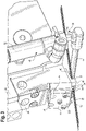
FIG. 3 is a perspective view of thefluid application device 10 according to an embodiment of the present invention. Referring toFIGS. 1 and3 , thefluid application device 10 further includes astrand engagement device 30. Thestrand engagement device 30 may be formed integrally with theapplicator head 16. Alternatively, thestrand engagement device 30 may be secured to theapplicator head 16 or other component of thefluid application device 10 with a suitable fastener, including, but not limited to, bolts, screws, rivets, adhesives, welds and the like. Thestrand engagement device 30 is configured to engage thestrands 12 and move thestrands 12 toward or away from theapplicator head 16 andnozzle assembly 22 based on a line condition (active or static) of thefluid application device 10, as discussed further below. - Referring still to
FIGS. 1 and3 , thenozzle assembly 22 includes aguide plate 32 to assist in positioning of thestrands 12 relative to theorifices 28 and outlets of thenozzle assembly 22. Theguide plate 32 includes at least oneguide slot 34 through which thestrand 12 is fed. Theguide slot 34 may be formed in a substantially inverted v-shape, with anopen end 36 ofguide slot 34 corresponding to a wide portion of the inverted v-shape, and aclosed end 38 of the guide slot correspond to a narrow portion of the inverted v-shape. Theclosed end 38 acts as a limit or stop for thestrand 12 to position thestrand 12 at the desired position relative theorifice 28 and outlets for application of the first fluid F1. That is, theclosed end 38 acts as a stop to position the strand 12 a predetermined distance, or gap G1, from theorifice 28. Thestrand 12 may either contact theclosed end 38 or be positioned in close proximity to theclosed end 38. The predetermined distance, or gap G1, between thestrand 12 andorifice 28 is a distance or gap where overspray may be reduced or minimized. In a direction of travel of thestrands 12, the at least oneguide slot 34 may be positioned before theorifices 28 of thenozzle assembly 22. - According to one embodiment of the present invention, the at least one
guide slot 34 may include threeguide slots 34. However, it is understood that the number ofguide slots 34 may vary, and is not limited to the example above. Eachguide slot 34 is associated with acorresponding orifice 28 of thenozzle assembly 22. That is, eachguide slot 34 is substantially aligned with acorresponding orifice 28 of the nozzle assembly. For example, theclosed end 38 ofrespective guide slots 34 may be aligned withrespective orifices 28 in the direction of travel of thestrands 12. Eachguide slot 34 is configured to receive aseparate strand 12, although it envisioned that more than onestrand 12 may be received in eachguide slot 34. - In one embodiment, the
nozzle assembly 22 includes abody portion 22a and theguide plate 32 is formed separately from thebody portion 22a. Theguide plate 32 may be formed by afirst flange 40 secured to theadapter 24 and asecond flange 42 depending from thefirst flange 40. The at least oneguide slot 34 may be formed in thesecond flange 42. Theguide plate 32 may be secured to theadapter 24 using known fastening techniques, and may be removed, independently of thebody portion 22a, for replacement and/or servicing. Alternatively, theguide plate 32 may be formed integrally with thebody portion 22a of thenozzle assembly 22. For example, theguide plate 32 may include a flange that depends from thebody portion 22a in which theguide slots 34 are formed. In another embodiment, theguide plate 32 may be removably secured to thenozzle assembly 22. That is, in one embodiment, theguide plate 32 may be formed integrally with thenozzle assembly 22 by being selectively releasably secured to thebody portion 22a of thenozzle assembly 22. For example, theguide plate 32 may be directly secured to thebody portion 22a using a known suitable fastener or fasteners. Accordingly, theguide plate 32 may be removed from thenozzle assembly 22, independent of thebody portion 22a for replacement or service. - With further reference to
FIG. 3 , thestrand engagement device 30 includes anengagement arm 44 configured to support and/or guide the strand orstrands 12. Theengagement arm 44 is adjustable to move thestrands 12 withinrespective guide slots 34 to accurately position thestrands 12 relative to therespective orifices 28 and outlets. -
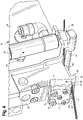
FIG. 3 shows theengagement arm 44 in a first position.FIG. 4 is a perspective view of thefluid application device 10 with theengagement arm 44 in a second position. That is, theengagement arm 44 is adjustable between a first position, as shown inFIG. 3 , and a second position, as shown inFIG. 4 . The first position corresponds to a position where theengagement arm 44 is spaced a first distance from theapplicator head 16. The first distance is sufficient to prevent or limit damage, such as burn through, to thestrands 12 caused from heat radiating from theapplicator head 16 and/ornozzle assembly 22. For example, theengagement arm 44, in the first position may space thestrands 12 approximately 3-5 mm from a heat source of theapplicator head 16. Moving theengagement arm 44 to, and maintaining theengagement arm 44 in, the first position may be beneficial when thefluid application device 10 is in a static line condition, where the strand are not being fed past thenozzle assembly 22. - The second position corresponds to a position where the
engagement arm 44 is spaced a second distance, less than the first distance, from theapplicator head 16, such that thestrands 12 are moved closer to theapplicator head 16 and therespective orifices 28. In one example, the second position of theengagement arm 44 positions the strands approximately 1-3 mm from theorifices 28 of therespective nozzle assembly 22, and more preferably, 1-2 mm. That is, the second position of theengagement arm 44 generally corresponds to the gap G1 over which the first fluid F1 is to be applied on thestrand 12. Moving theengagement arm 44 to, and maintaining the engagement arm in, the second position may be beneficial when thefluid application device 10 is in an active line condition, so that the first fluid F1 may be efficiently applied on thestrands 12. - Referring still to
FIGS. 3 and4 , theengagement arm 44 is adjusted by an actuatingassembly 48. The actuatingassembly 48 is apneumatically controlledpiston 50 andcylinder 52. Thepiston 50 is movable with in acylinder 52 in response to air or another gas being introduced into thecylinder 52. Thepiston 50 is connected directly or indirectly to theengagement arm 44 such that movement of thepiston 50 in and out of thecylinder 52 causes theengagement arm 44 to move toward or away from theapplicator head 16. - Referring still to
FIGS. 3 and4 , thenozzle assembly 22 may be formed as a modular unit. That is, thenozzle assembly 22 may be selectively removed from and secured to thefluid application device 10. For example, thenozzle assembly 22 may be selectively removed from and secured to theapplicator head 16, and more specifically, in some embodiments, theadapter 24. Accordingly, thenozzle assembly 22 may be replaced in the event a newer or different nozzle assembly is desired or required. Thenozzle assembly 22 is selectively removable from and securable to thefluid application device 10 by way of at least one securing element 74 (FIG. 4 ). In an exemplary embodiment, thenozzle assembly 22 includes at least one securingopening 76 extending therethrough, each securingopening 76 configured to receive arespective securing element 74. - With further reference to
FIGS. 3 and4 , in one embodiment, thenozzle assembly 22 may include two securingopenings 76, each configured to receive arespective securing element 74. It is understood that the number of securingopenings 76 is not limited to the example above, however. Individual securingopenings 76 may be formed as an opening or slot extending through thenozzle assembly 22. The opening or slot may be closed about its periphery or include an open side along an edge of thenozzle assembly 22. The securingelements 74 extend through the securingopenings 76 and are received in corresponding bores (not shown) in thefluid application device 10 to secure thenozzle assembly 22 to theapplicator head 16. This allows for a modular design of thefluid application device 10 andnozzle assembly 22, such that thenozzle assembly 22 may be replaced without alternations to, or replacement of additional parts on, thefluid application device 10. - In use, the at least one
strand 12 may be fed past thenozzle assembly 22, and in particular, past theorifice 28. As described above, the at least onestrand 12 extends across theengagement arm 44 of thestrand engagement device 30. Movement of theengagement arm 44 by the actuatingassembly 48 moves the at least onestrand 12 within acorresponding guide slot 34 toward theorifice 28 to a position approximately 0-2 mm from theorifice 28, for application of the adhesive to thestrand 12. The actuatingassembly 48 may also control theengagement arm 44 to move away from theorifice 28, for example, during a static line condition of thefluid application device 10. - The adhesive may be received in the
orifice 28 via the first conduit (not shown) in thenozzle assembly 18. The second fluid F2, or air, may be received in theoutlets 29 positioned adjacent to theorifice 28 via a second conduit (not shown). The adhesive is discharged through theorifice 28 for application to the strand ofmaterial 12 and the air may be discharged from theoutlets 29 to cause the adhesive to oscillate during application, so as to be applied across thestrand 12 as the strand is fed by theorifice 28. The adhesive may be discharged from theorifice 28 as a filament for application on thestrand 12. - In the examples described above, the
strands 12 may be fed by thefluid application device 10 at a higher speed than in traditional non-contact nozzle applications. For example, thestrands 12 may be fed past thenozzle assembly 22 at speeds ranging from 4001000 mpm. In one example, the line speed may be 400-800 mpm, and more particularly, around 700 mpm. This may correspond to a production rate of 1000-1500 products per minute, for example. Compared to traditional non-contact nozzle assembly, the higher line speed in the examples above is a result, in part, of the closer proximity of thestrands 12 to theorifices 28. That is, by positioning the strands in close proximity, preferably 0-2 mm fromrespective orifices 28, the line speed may be increased while still maintaining adequate adhesive application on the strands. That is, by positioning thestrands 12 closer to theorifices 28, overspray may be reduced, thereby allowing more efficient application of the first fluid onto thestrands 12, which, in turn, allows for thestrands 12 to fed through at a higher line speed. Proper positioning of thestrands 12 is assisted by thestrand engagement device 30 and the closed ends 38 of theguide slots 34. In addition, the width of theorifices 28 may be increased compared to traditional non-contact configurations to more efficiently apply the first fluid. - As described above, the second fluid F2 is discharged through the outlets to control application of the first fluid F1, or adhesive, on the
strands 12. For example, the second fluid F2 may oscillate the first fluid F1 so that the first fluid F1 is applied on thestrands 12 in a substantially sinusoidal pattern. Other patterns may be applied as well by varying the discharge of the second fluid F2. With the sinusoidal pattern, the first fluid F1 is applied over a wider range of thestrand 12. In addition, this pattern allows for thestrand 12 to be adhered to thesubstrate 14 at discrete points or segments along the length of the strand, rather than along the entire length of the strand. Accordingly, strand may stretch or relax between the adhered points or segments independently of thesubstrate 14. -
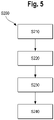
FIG. 5 is a diagram showing a method of applying a first fluid F1, such as an adhesive, to a moving article, such as a strand of material. The method is shown generally at S200 and is performed at thenozzle assembly 18 described above. In one embodiment, as shown at S210, the method includes positioning the article orstrand 12 at theclosed end 38 of the guide slot so that the article or strand is spaced a predetermined distance or gap G1 from theorifice 28. Thestrand 12 may be positioned, for example, at a distance of 1-3mm, and more preferably, 1-2 mm from theorifice 28. At S220, the article orstrand 12 is fed through the guide slot and the past theorifice 28 at a predetermined speed. Thestrand 24 isfed by the orifice at speeds up to approximately 1000 mpm. In one embodiment, the article orstrand 12 is fed by theorifice 28 at approximately 700 mpm. At S230, the first fluid F1 is applied to the article or strand 12 from theorifice 28. The first fluid F1 may be an adhesive, discharged from theorifice 28 as an adhesive filament. The adhesive is applied to thestrand 12 in a non-contacting manner. At S240, the second fluid F2 is discharged from at least oneoutlet 29 adjacent to theorifice 28 to oscillate the first fluid F1, so that the first fluid F1 may be applied all around thestrand 12 in a desired pattern. For example, the first fluid F1 may be oscillated by the second fluid F2 to be applied to the strand in a substantially sinusoidal pattern. The first fluid F1 may be applied to the strand orstrands 12 with the strand orstrands 12 in either of a stretched condition or relaxed condition, depending on a desired application of the substrate, i.e., the nonwoven material or article, to which thestrand 12 is to be bonded. - In the embodiments above, the
nozzle assembly 22 is formed as a non-contact nozzle assembly. In a non-contact nozzle assembly, the first fluid F1 is discharged from anorifice 28 over a gap to be received on thestrand 12. That is, in a non-contact nozzle, the nozzle, and in particular, an orifice discharging a first fluid F1, is spaced from thestrand 12 during the fluid application process. In addition, in the non-contact nozzle, the second fluid F2 is discharged from at least one outlet adjacent torespective orifices 28 of thenozzle assembly 22. The second fluid F2 is used to control the application of the first fluid F1 on thestrand 12, for example, by oscillating the first fluid F1 as it is applied. Accordingly, the first fluid F1 may be applied on thestrand 12 in a desired pattern. In addition, by controlling application of the first fluid F1 with the second fluid F2 provides a stitching effect and fluid movement around the strand to provide creep resistance and consistent band retention. - Further, in the examples above, it is understood that the number of
strands 12,orifices 28,outlets 29, and guideslots 34 may vary. For example, the fluid application may be able to accommodate anywhere from 1 to 10 strands, but is not limited thereto. For example, theguide plate 32 may include anywhere from 1 to 10 guide slots. A corresponding number of orifices may be provided on thenozzle assembly 22, such that at least oneorifice 28 corresponds to, and is generally aligned with, eachguide slot 34. At least oneoutlet 29 is provided for eachorifice 28 as described above. Astrand 12 is received in eachguide slot 34. - The
strands 12, coated with the first fluid F1, may be applied and adhered to thesubstrate 14, i.e., the nonwoven material. The nonwoven material may be used in, for example, manufacture of disposable hygiene products, including but not limited to, baby diapers and pull-on products, adult diapers and incontinence products, feminine hygienic products, medical/hospital pads, light incontinence products, wipes or other nonwoven or film laminated articles used in a hygienic end product using elasticated strands of material.
Claims (12)
- A fluid application device (10), comprising:- an applicator head (16); and- a nozzle assembly (22) fluidly coupled to the applicator head (16), the nozzle assembly (22) comprising:- a guide slot (34) configured to receive a strand (12) of material, the guide slot (34) having an open end (36) and a closed end (38);- an orifice (28) configured to discharge a first fluid (F1) onto the strand (12), wherein the guide slot (34) is spaced from the orifice (28); and- at least one outlet (29) adjacent to the orifice (28), the at least one outlet (29) configured to discharge a second fluid (F2) to act on the first fluid (F1) discharged from the orifice (28);wherein the closed end (38) of the guide slot (34) defines a stop configured to space the strand (12) a predetermined distance from the orifice (28) such that the first fluid (F1) is discharged from the orifice (28) over the predetermined distance onto the strand (12), andfurther comprising a strand engagement device (30), the strand engagement device (30) comprising an engagement arm (44) configured to engage the strand (12) of material and adjust a position of the strand (12) of material in the guide slot (34) and relative to the orifice (28),wherein the engagement arm (44) is adjustable by an actuating assembly (48) between a first position in which it is spaced a first distance from the applicator head (16), and a second position in which it is spaced a second distance from the applicator head (16),characterized bythe actuating assembly (48) being a pneumatically controlled piston (50) and cylinder (52), wherein the piston (50) is movable within the cylinder (52) in response to air or another gas being introduced into the cylinder (52), said piston (50) being connected directly or indirectly to the engagement arm (44) such that movement of the piston (50) in and out of the cylinder (52) causes the engagement arm (44) to move toward or away from the applicator head (16).
- The fluid application device (10) of claim 1,
further comprising more than one guide slot (34) and more than one orifice (28). - The fluid application device (10) of claim 1,
further comprising three guide slots (34) and three orifices (28). - The fluid application device (10) of one of the preceding claims,
wherein the nozzle assembly (22) further comprises at least one securing opening (76) configured to receive a respective securing element (74) to selectively and releasably secure the nozzle assembly (22) to the applicator head (16). - The fluid application device (10) of claim 4,
wherein the at least one securing opening (76) includes two securing openings (76). - The fluid application device (10) of one of the preceding claims,
wherein the applicator head (16) further comprises an adapter (24) and the nozzle assembly (22) is secured to the adapter (24). - The fluid application device (10) of one of the preceding claims,
wherein the nozzle assembly (22) further comprises a guide plate (32), and the guide slot (34) is formed on the guide plate (32). - The fluid application device (10) of one of the preceding claims,
wherein the first fluid (F1) is an adhesive and the second fluid (F2) is air. - A method of applying a fluid with a fluid application device (10) as defined in claim 1 to a strand (12) of material, the fluid application device (10) comprising a nozzle assembly (22) comprising a guide slot (34) configured to receive the strand (12) passing therethrough, the guide slot (34) having an open end (36) and a closed end (38), an orifice (28) spaced from the closed end (38) and configured to discharge a first fluid (F1) therefrom, and at least one outlet adjacent to the orifice (28) configured to discharge a second fluid (F2) to control application of the first fluid (F1) onto the strand (12), the method comprising:- positioning the strand (12) at the closed end (38) of the guide slot (34) so that the strand (12) is spaced a predetermined distance from the orifice (28);- feeding the strand (12) through the guide slot (34) at a predetermined speed;- applying the first fluid (F1) onto the strand (12) from the orifice (28) over the predetermined distance; and- discharging the second fluid (F2) from the at least one outlet (29) to control application of the first fluid (F1) onto the strand (12).
- The method of claim 9,
wherein the first fluid (F1) is and adhesive and the second fluid (F2) is air. - The method of claim 9 or 10,
wherein the predetermined distance is 0-2 mm. - The method of one of claims 9 to 11,
wherein the predetermined speed is up to 1000m/min.
Applications Claiming Priority (3)
| Application Number | Priority Date | Filing Date | Title |
|---|---|---|---|
| US201361904317P | 2013-11-14 | 2013-11-14 | |
| US14/525,498 US9908137B2 (en) | 2013-11-14 | 2014-10-28 | Fluid application device having a modular non-contact nozzle for applying fluid to an article |
| PCT/US2014/065250 WO2015073552A1 (en) | 2013-11-14 | 2014-11-12 | Fluid application device having a modular non-contact nozzle for applying fluid to an article |
Publications (2)
| Publication Number | Publication Date |
|---|---|
| EP3068550A1 EP3068550A1 (en) | 2016-09-21 |
| EP3068550B1 true EP3068550B1 (en) | 2022-09-21 |
Family
ID=53044018
Family Applications (1)
| Application Number | Title | Priority Date | Filing Date |
|---|---|---|---|
| EP14805453.9A Active EP3068550B1 (en) | 2013-11-14 | 2014-11-12 | Fluid application device having a modular non-contact nozzle for applying fluid to an article |
Country Status (7)
| Country | Link |
|---|---|
| US (1) | US9908137B2 (en) |
| EP (1) | EP3068550B1 (en) |
| JP (1) | JP6633521B2 (en) |
| CN (1) | CN105916596B (en) |
| CA (1) | CA2924215C (en) |
| ES (1) | ES2932604T3 (en) |
| WO (1) | WO2015073552A1 (en) |
Families Citing this family (1)
| Publication number | Priority date | Publication date | Assignee | Title |
|---|---|---|---|---|
| WO2020097354A2 (en) * | 2018-11-09 | 2020-05-14 | Illinois Tool Works Inc. | Modular fluid application device for varying fluid coat weight |
Citations (2)
| Publication number | Priority date | Publication date | Assignee | Title |
|---|---|---|---|---|
| US6077375A (en) * | 1998-04-15 | 2000-06-20 | Illinois Tool Works Inc. | Elastic strand coating process |
| US20090000545A1 (en) * | 2007-06-29 | 2009-01-01 | Illinois Tool Works Inc. | Strand positioning guide having reversely oriented V-shaped slots for use in connection with strand coating applicators |
Family Cites Families (17)
| Publication number | Priority date | Publication date | Assignee | Title |
|---|---|---|---|---|
| US3529571A (en) | 1968-10-08 | 1970-09-22 | Westinghouse Electric Corp | Wire marking machine |
| US3997128A (en) | 1974-12-18 | 1976-12-14 | The Furukawa Electric Co., Ltd. | Wire take up apparatus |
| US5289767A (en) | 1992-08-21 | 1994-03-01 | Videojet Systems International, Inc. | Method and apparatus for guiding an elongated generally cylindrical member past a non-contact printing station |
| US5389151A (en) | 1993-03-15 | 1995-02-14 | Nordson Corporation | Interchangeable contact/non-contact dispensing system |
| US6001178A (en) | 1997-05-13 | 1999-12-14 | Nordson Corporation | Method and apparatus for applying uniform layers of adhesive to contoured surfaces of a substrate |
| US6368409B1 (en) | 1997-11-25 | 2002-04-09 | Nordson Corporation | Electrostatic dispensing apparatus and method |
| WO1999054057A1 (en) | 1998-04-17 | 1999-10-28 | Nordson Corporation | Method and apparatus for applying a controlled pattern of fibrous material to a moving substrate |
| US6361634B1 (en) * | 2000-04-05 | 2002-03-26 | Kimberly-Clark Worldwide, Inc. | Multiple stage coating of elastic strands with adhesive |
| US6520237B1 (en) | 2000-07-24 | 2003-02-18 | Illinois Tool Works Inc | Variable spacing strand coating system and method |
| US6619566B2 (en) | 2001-03-22 | 2003-09-16 | Nordson Corporation | Universal dispensing system for air assisted extrusion of liquid filaments |
| US6582518B2 (en) | 2001-03-23 | 2003-06-24 | Nordson Corporation | Guide system for positioning an elongated strand in a liquid dispensing environment |
| US7578882B2 (en) * | 2003-01-22 | 2009-08-25 | Nordson Corporation | Module, nozzle and method for dispensing controlled patterns of liquid material |
| US7462240B2 (en) | 2003-01-24 | 2008-12-09 | Nordson Corporation | Module, nozzle and method for dispensing controlled patterns of liquid material |
| US7067009B2 (en) | 2004-06-09 | 2006-06-27 | Illinois Tool Works Inc. | Strand guide implements or mechanisms for use in connection with material dispensing and coating nozzles |
| EP2109510B1 (en) | 2006-09-25 | 2014-02-12 | SMS Siemag AG | Method and apparatus for winding up metal strips onto a winding mandrel |
| EP2142309B1 (en) | 2007-04-03 | 2014-10-22 | Nordson Corporation | Protective member and nozzle assembly configured to resist wear |
| MX352005B (en) | 2011-04-11 | 2017-11-07 | Nordson Corp | System, nozzle, and method for coating elastic strands. |
-
2014
- 2014-10-28 US US14/525,498 patent/US9908137B2/en active Active
- 2014-11-12 WO PCT/US2014/065250 patent/WO2015073552A1/en active Application Filing
- 2014-11-12 ES ES14805453T patent/ES2932604T3/en active Active
- 2014-11-12 CA CA2924215A patent/CA2924215C/en active Active
- 2014-11-12 CN CN201480059064.7A patent/CN105916596B/en active Active
- 2014-11-12 JP JP2016530886A patent/JP6633521B2/en active Active
- 2014-11-12 EP EP14805453.9A patent/EP3068550B1/en active Active
Patent Citations (2)
| Publication number | Priority date | Publication date | Assignee | Title |
|---|---|---|---|---|
| US6077375A (en) * | 1998-04-15 | 2000-06-20 | Illinois Tool Works Inc. | Elastic strand coating process |
| US20090000545A1 (en) * | 2007-06-29 | 2009-01-01 | Illinois Tool Works Inc. | Strand positioning guide having reversely oriented V-shaped slots for use in connection with strand coating applicators |
Also Published As
| Publication number | Publication date |
|---|---|
| ES2932604T3 (en) | 2023-01-23 |
| JP2016538432A (en) | 2016-12-08 |
| EP3068550A1 (en) | 2016-09-21 |
| CN105916596B (en) | 2019-11-19 |
| US20150132481A1 (en) | 2015-05-14 |
| CN105916596A (en) | 2016-08-31 |
| WO2015073552A1 (en) | 2015-05-21 |
| JP6633521B2 (en) | 2020-01-22 |
| CA2924215C (en) | 2018-10-16 |
| CA2924215A1 (en) | 2015-05-21 |
| US9908137B2 (en) | 2018-03-06 |
Similar Documents
| Publication | Publication Date | Title |
|---|---|---|
| US10213804B2 (en) | Fluid application device having a modular contact nozzle with a fluidic oscillator | |
| EP2679313B1 (en) | Method and apparatus for applying adhesive on an elastic strand in a personal disposable hygiene product | |
| EP3068549B1 (en) | Fluid application device having a modular nozzle assembly for applying fluid to an article | |
| EP3068550B1 (en) | Fluid application device having a modular non-contact nozzle for applying fluid to an article | |
| EP3179972A1 (en) | Method for applying adhesive on an elastic strand in assembly of a personal disposable hygiene product | |
| US10737287B2 (en) | Fluid application device having a modular contact nozzle with a fluidic oscillator | |
| US9932704B2 (en) | Fluid application device, strand engagement device and method of controlling the same | |
| US10421095B2 (en) | Modular fluid application device compatible with different nozzle configurations |
Legal Events
| Date | Code | Title | Description |
|---|---|---|---|
| PUAI | Public reference made under article 153(3) epc to a published international application that has entered the european phase |
Free format text: ORIGINAL CODE: 0009012 |
|
| 17P | Request for examination filed |
Effective date: 20160324 |
|
| AK | Designated contracting states |
Kind code of ref document: A1 Designated state(s): AL AT BE BG CH CY CZ DE DK EE ES FI FR GB GR HR HU IE IS IT LI LT LU LV MC MK MT NL NO PL PT RO RS SE SI SK SM TR |
|
| AX | Request for extension of the european patent |
Extension state: BA ME |
|
| DAX | Request for extension of the european patent (deleted) | ||
| STAA | Information on the status of an ep patent application or granted ep patent |
Free format text: STATUS: EXAMINATION IS IN PROGRESS |
|
| 17Q | First examination report despatched |
Effective date: 20181207 |
|
| STAA | Information on the status of an ep patent application or granted ep patent |
Free format text: STATUS: EXAMINATION IS IN PROGRESS |
|
| STAA | Information on the status of an ep patent application or granted ep patent |
Free format text: STATUS: EXAMINATION IS IN PROGRESS |
|
| GRAP | Despatch of communication of intention to grant a patent |
Free format text: ORIGINAL CODE: EPIDOSNIGR1 |
|
| STAA | Information on the status of an ep patent application or granted ep patent |
Free format text: STATUS: GRANT OF PATENT IS INTENDED |
|
| INTG | Intention to grant announced |
Effective date: 20220413 |
|
| GRAS | Grant fee paid |
Free format text: ORIGINAL CODE: EPIDOSNIGR3 |
|
| GRAA | (expected) grant |
Free format text: ORIGINAL CODE: 0009210 |
|
| STAA | Information on the status of an ep patent application or granted ep patent |
Free format text: STATUS: THE PATENT HAS BEEN GRANTED |
|
| AK | Designated contracting states |
Kind code of ref document: B1 Designated state(s): AL AT BE BG CH CY CZ DE DK EE ES FI FR GB GR HR HU IE IS IT LI LT LU LV MC MK MT NL NO PL PT RO RS SE SI SK SM TR |
|
| REG | Reference to a national code |
Ref country code: GB Ref legal event code: FG4D |
|
| REG | Reference to a national code |
Ref country code: CH Ref legal event code: EP |
|
| REG | Reference to a national code |
Ref country code: IE Ref legal event code: FG4D |
|
| REG | Reference to a national code |
Ref country code: DE Ref legal event code: R096 Ref document number: 602014085006 Country of ref document: DE |
|
| REG | Reference to a national code |
Ref country code: AT Ref legal event code: REF Ref document number: 1519707 Country of ref document: AT Kind code of ref document: T Effective date: 20221015 |
|
| REG | Reference to a national code |
Ref country code: LT Ref legal event code: MG9D |
|
| REG | Reference to a national code |
Ref country code: ES Ref legal event code: FG2A Ref document number: 2932604 Country of ref document: ES Kind code of ref document: T3 Effective date: 20230123 |
|
| REG | Reference to a national code |
Ref country code: NL Ref legal event code: MP Effective date: 20220921 |
|
| PG25 | Lapsed in a contracting state [announced via postgrant information from national office to epo] |
Ref country code: SE Free format text: LAPSE BECAUSE OF FAILURE TO SUBMIT A TRANSLATION OF THE DESCRIPTION OR TO PAY THE FEE WITHIN THE PRESCRIBED TIME-LIMIT Effective date: 20220921 Ref country code: RS Free format text: LAPSE BECAUSE OF FAILURE TO SUBMIT A TRANSLATION OF THE DESCRIPTION OR TO PAY THE FEE WITHIN THE PRESCRIBED TIME-LIMIT Effective date: 20220921 Ref country code: NO Free format text: LAPSE BECAUSE OF FAILURE TO SUBMIT A TRANSLATION OF THE DESCRIPTION OR TO PAY THE FEE WITHIN THE PRESCRIBED TIME-LIMIT Effective date: 20221221 Ref country code: LV Free format text: LAPSE BECAUSE OF FAILURE TO SUBMIT A TRANSLATION OF THE DESCRIPTION OR TO PAY THE FEE WITHIN THE PRESCRIBED TIME-LIMIT Effective date: 20220921 Ref country code: LT Free format text: LAPSE BECAUSE OF FAILURE TO SUBMIT A TRANSLATION OF THE DESCRIPTION OR TO PAY THE FEE WITHIN THE PRESCRIBED TIME-LIMIT Effective date: 20220921 Ref country code: FI Free format text: LAPSE BECAUSE OF FAILURE TO SUBMIT A TRANSLATION OF THE DESCRIPTION OR TO PAY THE FEE WITHIN THE PRESCRIBED TIME-LIMIT Effective date: 20220921 |
|
| REG | Reference to a national code |
Ref country code: AT Ref legal event code: MK05 Ref document number: 1519707 Country of ref document: AT Kind code of ref document: T Effective date: 20220921 |
|
| PG25 | Lapsed in a contracting state [announced via postgrant information from national office to epo] |
Ref country code: HR Free format text: LAPSE BECAUSE OF FAILURE TO SUBMIT A TRANSLATION OF THE DESCRIPTION OR TO PAY THE FEE WITHIN THE PRESCRIBED TIME-LIMIT Effective date: 20220921 Ref country code: GR Free format text: LAPSE BECAUSE OF FAILURE TO SUBMIT A TRANSLATION OF THE DESCRIPTION OR TO PAY THE FEE WITHIN THE PRESCRIBED TIME-LIMIT Effective date: 20221222 |
|
| PG25 | Lapsed in a contracting state [announced via postgrant information from national office to epo] |
Ref country code: SM Free format text: LAPSE BECAUSE OF FAILURE TO SUBMIT A TRANSLATION OF THE DESCRIPTION OR TO PAY THE FEE WITHIN THE PRESCRIBED TIME-LIMIT Effective date: 20220921 Ref country code: RO Free format text: LAPSE BECAUSE OF FAILURE TO SUBMIT A TRANSLATION OF THE DESCRIPTION OR TO PAY THE FEE WITHIN THE PRESCRIBED TIME-LIMIT Effective date: 20220921 Ref country code: PT Free format text: LAPSE BECAUSE OF FAILURE TO SUBMIT A TRANSLATION OF THE DESCRIPTION OR TO PAY THE FEE WITHIN THE PRESCRIBED TIME-LIMIT Effective date: 20230123 Ref country code: CZ Free format text: LAPSE BECAUSE OF FAILURE TO SUBMIT A TRANSLATION OF THE DESCRIPTION OR TO PAY THE FEE WITHIN THE PRESCRIBED TIME-LIMIT Effective date: 20220921 Ref country code: AT Free format text: LAPSE BECAUSE OF FAILURE TO SUBMIT A TRANSLATION OF THE DESCRIPTION OR TO PAY THE FEE WITHIN THE PRESCRIBED TIME-LIMIT Effective date: 20220921 |
|
| PG25 | Lapsed in a contracting state [announced via postgrant information from national office to epo] |
Ref country code: SK Free format text: LAPSE BECAUSE OF FAILURE TO SUBMIT A TRANSLATION OF THE DESCRIPTION OR TO PAY THE FEE WITHIN THE PRESCRIBED TIME-LIMIT Effective date: 20220921 Ref country code: PL Free format text: LAPSE BECAUSE OF FAILURE TO SUBMIT A TRANSLATION OF THE DESCRIPTION OR TO PAY THE FEE WITHIN THE PRESCRIBED TIME-LIMIT Effective date: 20220921 Ref country code: IS Free format text: LAPSE BECAUSE OF FAILURE TO SUBMIT A TRANSLATION OF THE DESCRIPTION OR TO PAY THE FEE WITHIN THE PRESCRIBED TIME-LIMIT Effective date: 20230121 Ref country code: EE Free format text: LAPSE BECAUSE OF FAILURE TO SUBMIT A TRANSLATION OF THE DESCRIPTION OR TO PAY THE FEE WITHIN THE PRESCRIBED TIME-LIMIT Effective date: 20220921 |
|
| REG | Reference to a national code |
Ref country code: DE Ref legal event code: R097 Ref document number: 602014085006 Country of ref document: DE |
|
| PG25 | Lapsed in a contracting state [announced via postgrant information from national office to epo] |
Ref country code: NL Free format text: LAPSE BECAUSE OF FAILURE TO SUBMIT A TRANSLATION OF THE DESCRIPTION OR TO PAY THE FEE WITHIN THE PRESCRIBED TIME-LIMIT Effective date: 20220921 Ref country code: MC Free format text: LAPSE BECAUSE OF FAILURE TO SUBMIT A TRANSLATION OF THE DESCRIPTION OR TO PAY THE FEE WITHIN THE PRESCRIBED TIME-LIMIT Effective date: 20220921 Ref country code: AL Free format text: LAPSE BECAUSE OF FAILURE TO SUBMIT A TRANSLATION OF THE DESCRIPTION OR TO PAY THE FEE WITHIN THE PRESCRIBED TIME-LIMIT Effective date: 20220921 |
|
| REG | Reference to a national code |
Ref country code: CH Ref legal event code: PL |
|
| P01 | Opt-out of the competence of the unified patent court (upc) registered |
Effective date: 20230606 |
|
| REG | Reference to a national code |
Ref country code: BE Ref legal event code: MM Effective date: 20221130 |
|
| PLBE | No opposition filed within time limit |
Free format text: ORIGINAL CODE: 0009261 |
|
| STAA | Information on the status of an ep patent application or granted ep patent |
Free format text: STATUS: NO OPPOSITION FILED WITHIN TIME LIMIT |
|
| PG25 | Lapsed in a contracting state [announced via postgrant information from national office to epo] |
Ref country code: LI Free format text: LAPSE BECAUSE OF NON-PAYMENT OF DUE FEES Effective date: 20221130 Ref country code: DK Free format text: LAPSE BECAUSE OF FAILURE TO SUBMIT A TRANSLATION OF THE DESCRIPTION OR TO PAY THE FEE WITHIN THE PRESCRIBED TIME-LIMIT Effective date: 20220921 Ref country code: CH Free format text: LAPSE BECAUSE OF NON-PAYMENT OF DUE FEES Effective date: 20221130 |
|
| 26N | No opposition filed |
Effective date: 20230622 |
|
| PG25 | Lapsed in a contracting state [announced via postgrant information from national office to epo] |
Ref country code: SI Free format text: LAPSE BECAUSE OF FAILURE TO SUBMIT A TRANSLATION OF THE DESCRIPTION OR TO PAY THE FEE WITHIN THE PRESCRIBED TIME-LIMIT Effective date: 20220921 Ref country code: LU Free format text: LAPSE BECAUSE OF NON-PAYMENT OF DUE FEES Effective date: 20221112 |
|
| PG25 | Lapsed in a contracting state [announced via postgrant information from national office to epo] |
Ref country code: IE Free format text: LAPSE BECAUSE OF NON-PAYMENT OF DUE FEES Effective date: 20221112 |
|
| PG25 | Lapsed in a contracting state [announced via postgrant information from national office to epo] |
Ref country code: FR Free format text: LAPSE BECAUSE OF NON-PAYMENT OF DUE FEES Effective date: 20221121 Ref country code: BE Free format text: LAPSE BECAUSE OF NON-PAYMENT OF DUE FEES Effective date: 20221130 |
|
| PGFP | Annual fee paid to national office [announced via postgrant information from national office to epo] |
Ref country code: GB Payment date: 20231127 Year of fee payment: 10 |
|
| PGFP | Annual fee paid to national office [announced via postgrant information from national office to epo] |
Ref country code: ES Payment date: 20231201 Year of fee payment: 10 |
|
| PGFP | Annual fee paid to national office [announced via postgrant information from national office to epo] |
Ref country code: IT Payment date: 20231122 Year of fee payment: 10 Ref country code: DE Payment date: 20231129 Year of fee payment: 10 |
|
| PG25 | Lapsed in a contracting state [announced via postgrant information from national office to epo] |
Ref country code: HU Free format text: LAPSE BECAUSE OF FAILURE TO SUBMIT A TRANSLATION OF THE DESCRIPTION OR TO PAY THE FEE WITHIN THE PRESCRIBED TIME-LIMIT; INVALID AB INITIO Effective date: 20141112 |