EP3067966A1 - Battery disconnect unit - Google Patents
Battery disconnect unit Download PDFInfo
- Publication number
- EP3067966A1 EP3067966A1 EP15187952.5A EP15187952A EP3067966A1 EP 3067966 A1 EP3067966 A1 EP 3067966A1 EP 15187952 A EP15187952 A EP 15187952A EP 3067966 A1 EP3067966 A1 EP 3067966A1
- Authority
- EP
- European Patent Office
- Prior art keywords
- middle cover
- lower case
- bdu
- relay terminal
- bar
- Prior art date
- Legal status (The legal status is an assumption and is not a legal conclusion. Google has not performed a legal analysis and makes no representation as to the accuracy of the status listed.)
- Granted
Links
Images


Classifications
-
- B—PERFORMING OPERATIONS; TRANSPORTING
- B60—VEHICLES IN GENERAL
- B60R—VEHICLES, VEHICLE FITTINGS, OR VEHICLE PARTS, NOT OTHERWISE PROVIDED FOR
- B60R16/00—Electric or fluid circuits specially adapted for vehicles and not otherwise provided for; Arrangement of elements of electric or fluid circuits specially adapted for vehicles and not otherwise provided for
- B60R16/02—Electric or fluid circuits specially adapted for vehicles and not otherwise provided for; Arrangement of elements of electric or fluid circuits specially adapted for vehicles and not otherwise provided for electric constitutive elements
- B60R16/03—Electric or fluid circuits specially adapted for vehicles and not otherwise provided for; Arrangement of elements of electric or fluid circuits specially adapted for vehicles and not otherwise provided for electric constitutive elements for supply of electrical power to vehicle subsystems or for
-
- H—ELECTRICITY
- H02—GENERATION; CONVERSION OR DISTRIBUTION OF ELECTRIC POWER
- H02J—ELECTRIC POWER NETWORKS; CIRCUIT ARRANGEMENTS OR SYSTEMS FOR SUPPLYING OR DISTRIBUTING ELECTRIC POWER; SYSTEMS FOR STORING ELECTRIC ENERGY
- H02J7/00—Circuit arrangements for charging or discharging batteries or for supplying loads from batteries
- H02J7/60—Circuit arrangements for charging or discharging batteries or for supplying loads from batteries including safety or protection arrangements
- H02J7/663—Circuit arrangements for charging or discharging batteries or for supplying loads from batteries including safety or protection arrangements using battery or load disconnect circuits
-
- B—PERFORMING OPERATIONS; TRANSPORTING
- B60—VEHICLES IN GENERAL
- B60L—PROPULSION OF ELECTRICALLY-PROPELLED VEHICLES; SUPPLYING ELECTRIC POWER FOR AUXILIARY EQUIPMENT OF ELECTRICALLY-PROPELLED VEHICLES; ELECTRODYNAMIC BRAKE SYSTEMS FOR VEHICLES IN GENERAL; MAGNETIC SUSPENSION OR LEVITATION FOR VEHICLES; MONITORING OPERATING VARIABLES OF ELECTRICALLY-PROPELLED VEHICLES; ELECTRIC SAFETY DEVICES FOR ELECTRICALLY-PROPELLED VEHICLES
- B60L3/00—Electric devices on electrically-propelled vehicles for safety purposes; Monitoring operating variables, e.g. speed, deceleration or energy consumption
- B60L3/0023—Detecting, eliminating, remedying or compensating for drive train abnormalities, e.g. failures within the drive train
- B60L3/0046—Detecting, eliminating, remedying or compensating for drive train abnormalities, e.g. failures within the drive train relating to electric energy storage systems, e.g. batteries or capacitors
-
- B—PERFORMING OPERATIONS; TRANSPORTING
- B60—VEHICLES IN GENERAL
- B60L—PROPULSION OF ELECTRICALLY-PROPELLED VEHICLES; SUPPLYING ELECTRIC POWER FOR AUXILIARY EQUIPMENT OF ELECTRICALLY-PROPELLED VEHICLES; ELECTRODYNAMIC BRAKE SYSTEMS FOR VEHICLES IN GENERAL; MAGNETIC SUSPENSION OR LEVITATION FOR VEHICLES; MONITORING OPERATING VARIABLES OF ELECTRICALLY-PROPELLED VEHICLES; ELECTRIC SAFETY DEVICES FOR ELECTRICALLY-PROPELLED VEHICLES
- B60L3/00—Electric devices on electrically-propelled vehicles for safety purposes; Monitoring operating variables, e.g. speed, deceleration or energy consumption
- B60L3/0092—Electric devices on electrically-propelled vehicles for safety purposes; Monitoring operating variables, e.g. speed, deceleration or energy consumption with use of redundant elements for safety purposes
-
- B—PERFORMING OPERATIONS; TRANSPORTING
- B60—VEHICLES IN GENERAL
- B60L—PROPULSION OF ELECTRICALLY-PROPELLED VEHICLES; SUPPLYING ELECTRIC POWER FOR AUXILIARY EQUIPMENT OF ELECTRICALLY-PROPELLED VEHICLES; ELECTRODYNAMIC BRAKE SYSTEMS FOR VEHICLES IN GENERAL; MAGNETIC SUSPENSION OR LEVITATION FOR VEHICLES; MONITORING OPERATING VARIABLES OF ELECTRICALLY-PROPELLED VEHICLES; ELECTRIC SAFETY DEVICES FOR ELECTRICALLY-PROPELLED VEHICLES
- B60L3/00—Electric devices on electrically-propelled vehicles for safety purposes; Monitoring operating variables, e.g. speed, deceleration or energy consumption
- B60L3/04—Cutting off the power supply under fault conditions
-
- H—ELECTRICITY
- H01—ELECTRIC ELEMENTS
- H01M—PROCESSES OR MEANS, e.g. BATTERIES, FOR THE DIRECT CONVERSION OF CHEMICAL ENERGY INTO ELECTRICAL ENERGY
- H01M50/00—Constructional details or processes of manufacture of the non-active parts of electrochemical cells other than fuel cells, e.g. hybrid cells
- H01M50/50—Current conducting connections for cells or batteries
- H01M50/572—Means for preventing undesired use or discharge
- H01M50/574—Devices or arrangements for the interruption of current
-
- H—ELECTRICITY
- H02—GENERATION; CONVERSION OR DISTRIBUTION OF ELECTRIC POWER
- H02J—ELECTRIC POWER NETWORKS; CIRCUIT ARRANGEMENTS OR SYSTEMS FOR SUPPLYING OR DISTRIBUTING ELECTRIC POWER; SYSTEMS FOR STORING ELECTRIC ENERGY
- H02J7/00—Circuit arrangements for charging or discharging batteries or for supplying loads from batteries
- H02J7/70—Circuit arrangements for charging or discharging batteries or for supplying loads from batteries characterised by the mechanical construction
- H02J7/751—Circuit arrangements for charging or discharging batteries or for supplying loads from batteries characterised by the mechanical construction concerning the insertion or the connection of the batteries
-
- B—PERFORMING OPERATIONS; TRANSPORTING
- B60—VEHICLES IN GENERAL
- B60Y—INDEXING SCHEME RELATING TO ASPECTS CROSS-CUTTING VEHICLE TECHNOLOGY
- B60Y2200/00—Type of vehicle
- B60Y2200/90—Vehicles comprising electric prime movers
- B60Y2200/91—Electric vehicles
-
- B—PERFORMING OPERATIONS; TRANSPORTING
- B60—VEHICLES IN GENERAL
- B60Y—INDEXING SCHEME RELATING TO ASPECTS CROSS-CUTTING VEHICLE TECHNOLOGY
- B60Y2200/00—Type of vehicle
- B60Y2200/90—Vehicles comprising electric prime movers
- B60Y2200/92—Hybrid vehicles
-
- H—ELECTRICITY
- H01—ELECTRIC ELEMENTS
- H01H—ELECTRIC SWITCHES; RELAYS; SELECTORS; EMERGENCY PROTECTIVE DEVICES
- H01H1/00—Contacts
- H01H1/58—Electric connections to or between contacts; Terminals
- H01H2001/5877—Electric connections to or between contacts; Terminals with provisions for direct mounting on a battery pole
-
- H—ELECTRICITY
- H01—ELECTRIC ELEMENTS
- H01M—PROCESSES OR MEANS, e.g. BATTERIES, FOR THE DIRECT CONVERSION OF CHEMICAL ENERGY INTO ELECTRICAL ENERGY
- H01M2200/00—Safety devices for primary or secondary batteries
-
- H—ELECTRICITY
- H01—ELECTRIC ELEMENTS
- H01M—PROCESSES OR MEANS, e.g. BATTERIES, FOR THE DIRECT CONVERSION OF CHEMICAL ENERGY INTO ELECTRICAL ENERGY
- H01M2220/00—Batteries for particular applications
- H01M2220/20—Batteries in motive systems, e.g. vehicle, ship, plane
-
- Y—GENERAL TAGGING OF NEW TECHNOLOGICAL DEVELOPMENTS; GENERAL TAGGING OF CROSS-SECTIONAL TECHNOLOGIES SPANNING OVER SEVERAL SECTIONS OF THE IPC; TECHNICAL SUBJECTS COVERED BY FORMER USPC CROSS-REFERENCE ART COLLECTIONS [XRACs] AND DIGESTS
- Y02—TECHNOLOGIES OR APPLICATIONS FOR MITIGATION OR ADAPTATION AGAINST CLIMATE CHANGE
- Y02E—REDUCTION OF GREENHOUSE GAS [GHG] EMISSIONS, RELATED TO ENERGY GENERATION, TRANSMISSION OR DISTRIBUTION
- Y02E60/00—Enabling technologies; Technologies with a potential or indirect contribution to GHG emissions mitigation
- Y02E60/10—Energy storage using batteries
-
- Y—GENERAL TAGGING OF NEW TECHNOLOGICAL DEVELOPMENTS; GENERAL TAGGING OF CROSS-SECTIONAL TECHNOLOGIES SPANNING OVER SEVERAL SECTIONS OF THE IPC; TECHNICAL SUBJECTS COVERED BY FORMER USPC CROSS-REFERENCE ART COLLECTIONS [XRACs] AND DIGESTS
- Y02—TECHNOLOGIES OR APPLICATIONS FOR MITIGATION OR ADAPTATION AGAINST CLIMATE CHANGE
- Y02T—CLIMATE CHANGE MITIGATION TECHNOLOGIES RELATED TO TRANSPORTATION
- Y02T10/00—Road transport of goods or passengers
- Y02T10/60—Other road transportation technologies with climate change mitigation effect
- Y02T10/70—Energy storage systems for electromobility, e.g. batteries
-
- Y—GENERAL TAGGING OF NEW TECHNOLOGICAL DEVELOPMENTS; GENERAL TAGGING OF CROSS-SECTIONAL TECHNOLOGIES SPANNING OVER SEVERAL SECTIONS OF THE IPC; TECHNICAL SUBJECTS COVERED BY FORMER USPC CROSS-REFERENCE ART COLLECTIONS [XRACs] AND DIGESTS
- Y02—TECHNOLOGIES OR APPLICATIONS FOR MITIGATION OR ADAPTATION AGAINST CLIMATE CHANGE
- Y02T—CLIMATE CHANGE MITIGATION TECHNOLOGIES RELATED TO TRANSPORTATION
- Y02T90/00—Enabling technologies or technologies with a potential or indirect contribution to GHG emissions mitigation
- Y02T90/40—Application of hydrogen technology to transportation, e.g. using fuel cells
Definitions
- the present disclosure relates to a battery disconnect unit (BDU), and particularly, to a BDU that is good in assemblability and couplability because a middle cover accommodated in a lower case stably supports a relay terminal and a guide bar and a hood structure are applied to the middle cover.
- BDU battery disconnect unit
- a BDU is equipped in electric vehicles and hybrid vehicles that produce energy by using a battery.
- the BDU is a module that is disposed between the battery and an inverter and includes a relay, a resister, and/or the like.
- the BDU stably supplies or breaks battery power to a power system of a vehicle, and when a fault current occurs, the BDU protects the power system of the vehicle.
- the related art relevant to BDUs may refer to a battery disconnect unit for electric vehicle disclosed in Korean Patent Registration No. 10-1185735 (family Nos. CN102340158A , EP02418750A3 , JP05174208B2 , and US08760002B2 ).
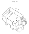
- FIG. 1 illustrates an internal perspective view of a related art BDU.
- a mounting part 3 is provided in a lower case 1, and a relay terminal 2 is fitted into the mounting part 3.
- a bus bar 4 is connected to one end of the relay terminal 2, and an electric component such as a relay (not shown) and/or the like is connected to the other end of the relay terminal 2.
- an aspect of the detailed description is to provide a BDU in which a relay terminal is stably fixed, the relay terminal is not damaged in maintenance and repair, and assemblability and couplability are good.
- a battery disconnect unit which is disposed between a battery and an inverter to stably supply or break power of the battery to a power system of a vehicle, includes: a lower case provided in a box shape with a top opened, a relay terminal hole into which a relay terminal is fitted being disposed on a bottom of the lower case; and a middle cover accommodated into and coupled to the lower case to press the relay terminal, an electric component being mounted on a top of the middle cover, wherein a first fixing hook capable of being fastened to the lower case is provided in the middle cover.
- the BDU may further include a guide bar vertically provided under the middle cover, the guide bar being a reference point in assembly.
- the BDU may further include a bar hole provided in the lower case, the guide bar being coupled to the bar hole.
- the BDU may further include a bus bar fixing bar provided in the middle cover to restrict vertical movement of the bus bar.
- the BDU may further include a side leg part provided to protrude in the middle cover, a fixing hole for fixing a signal bus bar being provided in the side leg part.
- the BDU may further include a second fixing hook provided at one end of the side leg part.
- the relay terminal hole into which the relay terminal is inserted is provided in the lower case, the relay terminal maintains a stable position without being laterally shaken.
- the relay terminal is not shaken upward and downward or detached.
- the fixing hook is provided in the middle cover and the middle cover is coupled to the lower case in a fitting-coupling method, assembly is easy, and a coupling force is good.
- the bus bar fixing bar which presses the bus bar to restrict vertical movement is provided in the middle cover, the bus bar is stably supported.
- the side leg part where the fixing hole for fixing the signal bus bar is provided is provided to protrude on one side of the middle cover, and the second fixing hook is provided at one end of the side leg part, whereby the signal bus bar is stably supported.
- FIG. 2 is a perspective view of a BDU according to an exemplary embodiment of the present invention.
- FIG. 3 is an exploded perspective view when a middle cover is detached from the BDU of FIG. 2 .
- FIG. 4 is a perspective view of the middle cover illustrated in FIG. 2 .
- FIG. 5 is a perspective view when a lower case is not provided in the BDU of FIG. 2 .
- FIG. 6 is a perspective view taken along a center line of FIG. 2 in a lengthwise direction.
- the BDU may be disposed between a battery and an inverter and may stably supply or break power of the battery to a power system of a vehicle.
- the BDU may include: a lower case 10 that is provided in a box shape with a top opened, a relay terminal hole 16 into which a relay terminal 15 is fitted being disposed on a bottom of the lower case 10; and a middle cover 20 that is accommodated into and coupled to the lower case 10 to press the relay terminal, an electric component being mounted on a top of the middle cover 20.
- a first fixing hook 22 capable of being fastened to the lower case 10 may be provided in the middle cover 20.
- the lower case 10 may be provided in a box shape with the top opened.
- a plurality of the relay terminal holes 16 may be provided in the bottom of the lower case 10.
- the relay terminal 15 may be fitted into the relay terminal hole 16.
- the relay terminal 15 may be a terminal that connects a bus bar 17 to an electric component (not shown) such as a relay, a resistor, a sensor, and/or the like. As the relay terminal 15 is fitted into the relay terminal hole 16 and fixed to the lower case 10, the relay terminal 15 maintains a stable position without being laterally shaken.
- the bus bar 17 which is connected to the relay terminal 15 at one end of the bus bar 17 may be disposed under the lower case 10 to avoid interference therebetween.
- the bus bar 17 may act as a connection path between a plurality of electric components or between a power source and a load.
- a bar hole 11 which a guide bar 21 of the middle cover 20 is inserted into and coupled to may be provided in the lower case 10.
- the bar hole 11 may be approximately disposed at a center portion of the middle cover 20.
- the guide bar 21 may be inserted into the bar hole 11, and thus, when the middle cover 20 is coupled to the lower case 10, the bar hole 11 may be used as an assembly reference point, thereby enhancing assemblability.
- a circular pipe supporter 12 may be provided near the bar hole 11.
- the circular pipe supporter 12 may be provided for stably supporting the guide bar 21.
- the circular pipe supporter 12 may be provided to have a certain height from a floor of the lower case 10.
- a hook hole 13 which the first fixing hook 22 of the middle cover 20 is inserted into and coupled to may be provided in plurality in the lower case 10.
- the first fixing hook 22 of the middle cover 20 may be fitted into the hook hole 13.
- a square pipe supporter 14 may be provided near the hook hole 13.
- the square pipe supporter 14 may be provided for stably supporting the first fixing hook 22.
- the middle cover 20 may be provided in a form capable of covering the inside of the lower case 10. Also, the middle cover 20 may be provided to have a size capable of being accommodated in the lower case 10. The middle cover 20 may be inserted into and coupled to the lower case 10 to press an upper end of the relay terminal 15. Since the middle cover 20 downward presses the relay terminal 15, the relay terminal 15 maintains a stable position without being upward and downward shaken. Therefore, even when an electric component such as a relay and/or the like is detached from the BDU, the relay terminal 15 stably maintains a coupling state without being shaken or detached, and thus, management and maintenance of components are easy.
- the guide bar 21 may be provided to protrude under the middle cover 20.
- the guide bar 21 may protrude in a cylindrical shape at a lower center portion of the middle cover 20.
- the guide bar 21 may be coupled to the bar hole 11 and thus may be used as a reference of an assembly position. Accordingly, assembly is easy.
- the first fixing hook 22 may be provided in plurality in the middle cover 20.
- the first fixing hook 22 may be provided as a fastening means that couples the middle cover 20 to the lower case 10. Since the first fixing hook 22 is provided, the middle cover 20 may be simply coupled to the lower case 10 in a fitting method, and thus, assembly is easy, thereby enhancing productivity.
- the plurality of first fixing hooks 22 may be symmetrically provided near the guide bar 21. Therefore, coupling stability is enhanced. That is, a pair of first fixing hooks 22 may be symmetrically provided near the guide bar 21, and thus, when the middle cover 20 is coupled to the lower case 10, a force may be applied in a direction where a hook opens outward to both sides. Accordingly, the middle cover 20 can endure a bidirectional external force, and thus, components cannot be easily detached from the BDU.
- a bus bar fixing bar 23, which presses the bus bar 17 mounted on the lower case 10 to restrict shaking or up, down, left, and right movements, may be provided in plurality in the middle cover 20.
- the bus bar 17 installed in the lower case 10 may be stably fixed by the bus bar fixing bar 23, and thus, a problem such as a contact failure and/or the like cannot occur when a current flows.
- a side leg part 24 may be provided to protrude in the middle cover 20.
- a fixing hole 25 for fixing a signal bus bar 18 may be provided in the side leg part 24.
- the fixing hole 25 may be provided in the side leg part 24 for fixing the signal bus bar 18 which deviates from the lower case 10 to one side.
- the signal bus bar 18 may be fitted into the fixing hole 25 and thus may be supported by the side leg part 24.
- a second fixing hook 26 may be provided in the side leg part 24.
- the second fixing hook 26 may be fixed and coupled to a portion of the lower case 10 and may stably support the signal bus bar 18.
- An electric component hole 27, into which an electric component such as a relay and/or the like is inserted to be connected to the relay terminal 15, may be provided in plurality in the top of the middle cover 20.
- An electric component, such as a relay, a resistor, a sensor, and/or the like, may be located on the middle cover 20 and may be connected to the relay terminal 15 through the electric component hole 27.
- an electric component is not illustrated in each of the drawings.
- the relay terminal hole into which the relay terminal is inserted is provided in the lower case, the relay terminal maintains a stable position without being laterally shaken.
- the relay terminal is not shaken upward and downward or detached.
- the fixing hook is provided in the middle cover and the middle cover is coupled to the lower case in a fitting-coupling method, assembly is easy, and a coupling force is good.
- the bus bar fixing bar which presses the bus bar to restrict vertical movement is provided in the middle cover, the bus bar is stably supported.
- the side leg part where the fixing hole for fixing the signal bus bar is provided is provided to protrude on one side of the middle cover, and the second fixing hook is provided at one end of the side leg part, whereby the signal bus bar is stably supported.
Landscapes
- Engineering & Computer Science (AREA)
- Power Engineering (AREA)
- Mechanical Engineering (AREA)
- Transportation (AREA)
- Sustainable Energy (AREA)
- Life Sciences & Earth Sciences (AREA)
- Sustainable Development (AREA)
- Chemical & Material Sciences (AREA)
- Electrochemistry (AREA)
- General Chemical & Material Sciences (AREA)
- Chemical Kinetics & Catalysis (AREA)
- Battery Mounting, Suspending (AREA)
- Connector Housings Or Holding Contact Members (AREA)
- Electric Propulsion And Braking For Vehicles (AREA)
- Connection Or Junction Boxes (AREA)
- Connecting Device With Holders (AREA)
- Combustion & Propulsion (AREA)
Abstract
Description
- The present disclosure relates to a battery disconnect unit (BDU), and particularly, to a BDU that is good in assemblability and couplability because a middle cover accommodated in a lower case stably supports a relay terminal and a guide bar and a hood structure are applied to the middle cover.
- Generally, a BDU is equipped in electric vehicles and hybrid vehicles that produce energy by using a battery. The BDU is a module that is disposed between the battery and an inverter and includes a relay, a resister, and/or the like. The BDU stably supplies or breaks battery power to a power system of a vehicle, and when a fault current occurs, the BDU protects the power system of the vehicle.
- The related art relevant to BDUs may refer to a battery disconnect unit for electric vehicle disclosed in Korean Patent Registration No.
10-1185735 CN102340158A ,EP02418750A3 JP05174208B2 US08760002B2 ). -
FIG. 1 illustrates an internal perspective view of a related art BDU. - A
mounting part 3 is provided in alower case 1, and arelay terminal 2 is fitted into themounting part 3. Abus bar 4 is connected to one end of therelay terminal 2, and an electric component such as a relay (not shown) and/or the like is connected to the other end of therelay terminal 2. - However, in the related art BDU, an element for fixing the
relay terminal 2 is not provided. For this reason, as therelay terminal 2 is shaken, a connection between therelay terminal 2 and the electric component becomes unstable. Also, when the electric component connected to therelay terminal 2 is detached from therelay terminal 2, it is unable to fix therelay terminal 2, and for this reason, maintenance is difficult. In addition, it is difficult to fix thebus bar 4 connected to therelay terminal 2. - Therefore, an aspect of the detailed description is to provide a BDU in which a relay terminal is stably fixed, the relay terminal is not damaged in maintenance and repair, and assemblability and couplability are good.
- To achieve these and other advantages and in accordance with the purpose of this specification, as embodied and broadly described herein, a battery disconnect unit (BDU), which is disposed between a battery and an inverter to stably supply or break power of the battery to a power system of a vehicle, includes: a lower case provided in a box shape with a top opened, a relay terminal hole into which a relay terminal is fitted being disposed on a bottom of the lower case; and a middle cover accommodated into and coupled to the lower case to press the relay terminal, an electric component being mounted on a top of the middle cover, wherein a first fixing hook capable of being fastened to the lower case is provided in the middle cover.
- Here, the BDU may further include a guide bar vertically provided under the middle cover, the guide bar being a reference point in assembly.
- Moreover, the BDU may further include a bar hole provided in the lower case, the guide bar being coupled to the bar hole.
- Moreover, the BDU may further include a bus bar fixing bar provided in the middle cover to restrict vertical movement of the bus bar.
- Moreover, the BDU may further include a side leg part provided to protrude in the middle cover, a fixing hole for fixing a signal bus bar being provided in the side leg part.
- Moreover, the BDU may further include a second fixing hook provided at one end of the side leg part.
- In the BDU according to an exemplary embodiment of the present invention, since the relay terminal hole into which the relay terminal is inserted is provided in the lower case, the relay terminal maintains a stable position without being laterally shaken.
- Moreover, since the middle cover coupled to the inside of the lower case downward presses the relay terminal, the relay terminal is not shaken upward and downward or detached.
- Moreover, since the guide bar which becomes a reference point in assembly is vertically provided under the middle cover, assembly is easy.
- Moreover, since the fixing hook is provided in the middle cover and the middle cover is coupled to the lower case in a fitting-coupling method, assembly is easy, and a coupling force is good.
- Moreover, since the bus bar fixing bar which presses the bus bar to restrict vertical movement is provided in the middle cover, the bus bar is stably supported.
- Moreover, the side leg part where the fixing hole for fixing the signal bus bar is provided is provided to protrude on one side of the middle cover, and the second fixing hook is provided at one end of the side leg part, whereby the signal bus bar is stably supported.
- Further scope of applicability of the present application will become more apparent from the detailed description given hereinafter. However, it should be understood that the detailed description and specific examples, while indicating preferred embodiments of the disclosure, are given by way of illustration only, since various changes and modifications within the spirit and scope of the disclosure will become apparent to those skilled in the art from the detailed description.
- The accompanying drawings, which are included to provide a further understanding of the disclosure and are incorporated in and constitute a part of this specification, illustrate exemplary embodiments and together with the description serve to explain the principles of the disclosure.
- In the drawings:
-
FIG. 1 illustrates an internal perspective view of a related art BDU; -
FIG. 2 is a perspective view of a BDU according to an exemplary embodiment of the present invention, and an electric component such as a relay and/or the like mounted on a middle cover is not illustrated; -
FIG. 3 is an exploded perspective view when a middle cover is detached from the BDU ofFIG. 2 ; -
FIG. 4 is a perspective view of the middle cover illustrated inFIG. 2 ; -
FIG. 5 is a perspective view when a lower case is not provided in the BDU ofFIG. 2 ; and -
FIG. 6 is a perspective view taken along a center line ofFIG. 2 in a lengthwise direction. - Description will now be given in detail of the exemplary embodiments, with reference to the accompanying drawings. For the sake of brief description with reference to the drawings, the same or equivalent components will be provided with the same reference numbers, and description thereof will not be repeated.
- Hereinafter, preferred embodiments of the present invention will be described in detail with reference to the accompanying drawings. However, the embodiments are provided only to disclose the invention in a manner sufficiently clear and complete for the invention to be easily carried out by a person having ordinary skill in the art to which the invention pertains, but do not mean to limit technical ideas and categories of the present invention.
-
FIG. 2 is a perspective view of a BDU according to an exemplary embodiment of the present invention.FIG. 3 is an exploded perspective view when a middle cover is detached from the BDU ofFIG. 2 .FIG. 4 is a perspective view of the middle cover illustrated inFIG. 2 .FIG. 5 is a perspective view when a lower case is not provided in the BDU ofFIG. 2 .FIG. 6 is a perspective view taken along a center line ofFIG. 2 in a lengthwise direction. A BDU according to exemplary embodiments of the present invention will be described in detail with reference to the accompanying drawings. - The BDU according to an exemplary embodiment of the present invention may be disposed between a battery and an inverter and may stably supply or break power of the battery to a power system of a vehicle. The BDU may include: a
lower case 10 that is provided in a box shape with a top opened, arelay terminal hole 16 into which arelay terminal 15 is fitted being disposed on a bottom of thelower case 10; and amiddle cover 20 that is accommodated into and coupled to thelower case 10 to press the relay terminal, an electric component being mounted on a top of themiddle cover 20. Afirst fixing hook 22 capable of being fastened to thelower case 10 may be provided in themiddle cover 20. - The
lower case 10 may be provided in a box shape with the top opened. A plurality of therelay terminal holes 16 may be provided in the bottom of thelower case 10. Therelay terminal 15 may be fitted into therelay terminal hole 16. Therelay terminal 15 may be a terminal that connects abus bar 17 to an electric component (not shown) such as a relay, a resistor, a sensor, and/or the like. As therelay terminal 15 is fitted into therelay terminal hole 16 and fixed to thelower case 10, therelay terminal 15 maintains a stable position without being laterally shaken. - The
bus bar 17 which is connected to therelay terminal 15 at one end of thebus bar 17 may be disposed under thelower case 10 to avoid interference therebetween. Thebus bar 17 may act as a connection path between a plurality of electric components or between a power source and a load. - A
bar hole 11 which aguide bar 21 of themiddle cover 20 is inserted into and coupled to may be provided in thelower case 10. Thebar hole 11 may be approximately disposed at a center portion of themiddle cover 20. Theguide bar 21 may be inserted into thebar hole 11, and thus, when themiddle cover 20 is coupled to thelower case 10, thebar hole 11 may be used as an assembly reference point, thereby enhancing assemblability. - A
circular pipe supporter 12 may be provided near thebar hole 11. Thecircular pipe supporter 12 may be provided for stably supporting theguide bar 21. Thecircular pipe supporter 12 may be provided to have a certain height from a floor of thelower case 10. - A
hook hole 13 which thefirst fixing hook 22 of themiddle cover 20 is inserted into and coupled to may be provided in plurality in thelower case 10. Thefirst fixing hook 22 of themiddle cover 20 may be fitted into thehook hole 13. - A
square pipe supporter 14 may be provided near thehook hole 13. Thesquare pipe supporter 14 may be provided for stably supporting thefirst fixing hook 22. - The
middle cover 20 may be provided in a form capable of covering the inside of thelower case 10. Also, themiddle cover 20 may be provided to have a size capable of being accommodated in thelower case 10. Themiddle cover 20 may be inserted into and coupled to thelower case 10 to press an upper end of therelay terminal 15. Since themiddle cover 20 downward presses therelay terminal 15, therelay terminal 15 maintains a stable position without being upward and downward shaken. Therefore, even when an electric component such as a relay and/or the like is detached from the BDU, therelay terminal 15 stably maintains a coupling state without being shaken or detached, and thus, management and maintenance of components are easy. - The
guide bar 21 may be provided to protrude under themiddle cover 20. Theguide bar 21 may protrude in a cylindrical shape at a lower center portion of themiddle cover 20. When themiddle cover 20 is coupled to thelower case 10, theguide bar 21 may be coupled to thebar hole 11 and thus may be used as a reference of an assembly position. Accordingly, assembly is easy. - The
first fixing hook 22 may be provided in plurality in themiddle cover 20. Thefirst fixing hook 22 may be provided as a fastening means that couples themiddle cover 20 to thelower case 10. Since thefirst fixing hook 22 is provided, themiddle cover 20 may be simply coupled to thelower case 10 in a fitting method, and thus, assembly is easy, thereby enhancing productivity. - The plurality of first fixing hooks 22 may be symmetrically provided near the
guide bar 21. Therefore, coupling stability is enhanced. That is, a pair of first fixing hooks 22 may be symmetrically provided near theguide bar 21, and thus, when themiddle cover 20 is coupled to thelower case 10, a force may be applied in a direction where a hook opens outward to both sides. Accordingly, themiddle cover 20 can endure a bidirectional external force, and thus, components cannot be easily detached from the BDU. - A bus
bar fixing bar 23, which presses thebus bar 17 mounted on thelower case 10 to restrict shaking or up, down, left, and right movements, may be provided in plurality in themiddle cover 20. Thebus bar 17 installed in thelower case 10 may be stably fixed by the busbar fixing bar 23, and thus, a problem such as a contact failure and/or the like cannot occur when a current flows. - A
side leg part 24 may be provided to protrude in themiddle cover 20. A fixinghole 25 for fixing asignal bus bar 18 may be provided in theside leg part 24. The fixinghole 25 may be provided in theside leg part 24 for fixing thesignal bus bar 18 which deviates from thelower case 10 to one side. Thesignal bus bar 18 may be fitted into the fixinghole 25 and thus may be supported by theside leg part 24. - A
second fixing hook 26 may be provided in theside leg part 24. Thesecond fixing hook 26 may be fixed and coupled to a portion of thelower case 10 and may stably support thesignal bus bar 18. - An
electric component hole 27, into which an electric component such as a relay and/or the like is inserted to be connected to therelay terminal 15, may be provided in plurality in the top of themiddle cover 20. An electric component, such as a relay, a resistor, a sensor, and/or the like, may be located on themiddle cover 20 and may be connected to therelay terminal 15 through theelectric component hole 27. In order to easily understand coupling between a case and a cover, an electric component is not illustrated in each of the drawings. - In the BDU according to an exemplary embodiment of the present invention, since the relay terminal hole into which the relay terminal is inserted is provided in the lower case, the relay terminal maintains a stable position without being laterally shaken.
- Moreover, since the middle cover coupled to the inside of the lower case downward presses the relay terminal, the relay terminal is not shaken upward and downward or detached.
- Moreover, since the guide bar which becomes a reference point in assembly is vertically provided under the middle cover, assembly is easy.
- Moreover, since the fixing hook is provided in the middle cover and the middle cover is coupled to the lower case in a fitting-coupling method, assembly is easy, and a coupling force is good.
- Moreover, since the bus bar fixing bar which presses the bus bar to restrict vertical movement is provided in the middle cover, the bus bar is stably supported.
- Moreover, the side leg part where the fixing hole for fixing the signal bus bar is provided is provided to protrude on one side of the middle cover, and the second fixing hook is provided at one end of the side leg part, whereby the signal bus bar is stably supported.
- The foregoing embodiments and advantages are merely exemplary and are not to be considered as limiting the present disclosure. The present teachings can be readily applied to other types of apparatuses. This description is intended to be illustrative, and not to limit the scope of the claims. Many alternatives, modifications, and variations will be apparent to those skilled in the art. The features, structures, methods, and other characteristics of the exemplary embodiments described herein may be combined in various ways to obtain additional and/or alternative exemplary embodiments.
- As the present features may be embodied in several forms without departing from the characteristics thereof, it should also be understood that the above-described embodiments are not limited by any of the details of the foregoing description, unless otherwise specified, but rather should be considered broadly within its scope as defined in the appended claims, and therefore all changes and modifications that fall within the metes and bounds of the claims, or equivalents of such metes and bounds are therefore intended to be embraced by the appended claims.
Claims (6)
- A battery disconnect unit (BDU) which is disposed between a battery and an inverter to stably supply or break power of the battery to a power system of a vehicle, the BDU comprising:a lower case (10) provided in a box shape with a top opened, a relay terminal hole (16) into which a relay terminal (15) is fitted being disposed on a bottom of the lower case; anda middle cover (20) accommodated into and coupled to the lower case (10) to press the relay terminal (15), an electric component being mounted on a top of the middle cover,wherein a first fixing hook (22) capable of being fastened to the lower case (10) is provided in the middle cover (20).
- The BDU of claim 1, further comprising a guide bar (21) vertically provided under the middle cover (20), the guide bar being a reference point in assembly.
- The BDU of claim 2, further comprising a bar hole (11) provided in the lower case (10), the guide bar (21) being coupled to the bar hole.
- The BDU of claim 1, further comprising a bus bar fixing bar (23) provided in the middle cover (20) to restrict vertical movement of the bus bar (17).
- The BDU of claim 1, further comprising a side leg part (24) provided to protrude in the middle cover (20), a fixing hole (25) for fixing a signal bus bar (18) being provided in the side leg part (24).
- The BDU of claim 5, further comprising a second fixing hook (26) provided at one end of the side leg part (24).
Applications Claiming Priority (1)
| Application Number | Priority Date | Filing Date | Title |
|---|---|---|---|
| KR1020150033876A KR102006187B1 (en) | 2015-03-11 | 2015-03-11 | Battery Disconnect Unit Cover |
Publications (2)
| Publication Number | Publication Date |
|---|---|
| EP3067966A1 true EP3067966A1 (en) | 2016-09-14 |
| EP3067966B1 EP3067966B1 (en) | 2018-01-31 |
Family
ID=54256587
Family Applications (1)
| Application Number | Title | Priority Date | Filing Date |
|---|---|---|---|
| EP15187952.5A Active EP3067966B1 (en) | 2015-03-11 | 2015-10-01 | Battery disconnect unit |
Country Status (6)
| Country | Link |
|---|---|
| US (1) | US9878681B2 (en) |
| EP (1) | EP3067966B1 (en) |
| JP (1) | JP6301893B2 (en) |
| KR (1) | KR102006187B1 (en) |
| CN (1) | CN105978050B (en) |
| ES (1) | ES2666145T3 (en) |
Cited By (1)
| Publication number | Priority date | Publication date | Assignee | Title |
|---|---|---|---|---|
| CN117936942A (en) * | 2023-12-29 | 2024-04-26 | 浙江吉利控股集团有限公司 | Battery pack and vehicle |
Families Citing this family (11)
| Publication number | Priority date | Publication date | Assignee | Title |
|---|---|---|---|---|
| KR102260830B1 (en) * | 2016-11-08 | 2021-06-03 | 삼성에스디아이 주식회사 | Rechargeable battery pack |
| KR101957962B1 (en) * | 2018-07-26 | 2019-03-14 | 이브이퓨처 주식회사 | Bracket for mounting inverter |
| JP7091945B2 (en) * | 2018-08-28 | 2022-06-28 | 住友電装株式会社 | Power relay device |
| CN109941110B (en) * | 2019-03-28 | 2023-09-15 | 武汉嘉晨汽车技术有限公司 | Battery pack circuit breaking unit protective cover with protective safety function |
| KR102122875B1 (en) * | 2019-10-24 | 2020-06-15 | 강토이앤씨(주) | Cable protect system of undergraund distribution line |
| JP7352833B2 (en) * | 2020-01-30 | 2023-09-29 | 株式会社オートネットワーク技術研究所 | circuit construct |
| CN113922007A (en) * | 2021-09-17 | 2022-01-11 | 东风时代(武汉)电池系统有限公司 | Split double layer BDU |
| DE102022211434A1 (en) | 2022-10-28 | 2024-05-08 | Robert Bosch Gesellschaft mit beschränkter Haftung | Switching unit |
| CN115579594B (en) * | 2022-12-07 | 2023-03-31 | 惠州亿纬锂能股份有限公司 | BDU box, BDU unit and PACK box |
| KR102872074B1 (en) * | 2023-09-13 | 2025-10-15 | 엘에스이모빌리티솔루션 주식회사 | Power device fixing apparatus |
| CN118156089B (en) * | 2024-05-11 | 2024-08-06 | 武汉嘉晨电子技术股份有限公司 | Battery pack circuit breaking unit and battery pack |
Citations (4)
| Publication number | Priority date | Publication date | Assignee | Title |
|---|---|---|---|---|
| WO1999058373A1 (en) * | 1998-05-12 | 1999-11-18 | Lear Automotive Dearborn, Inc. | Electric junction box for an automotive vehicle |
| US20020031924A1 (en) * | 1998-06-22 | 2002-03-14 | Davis Ruel Emmett | Modular terminal fuse block |
| CN102340158A (en) | 2010-07-16 | 2012-02-01 | Ls产电株式会社 | Structure of battery disconnection unit for electric vehicle |
| US20140041928A1 (en) * | 2012-08-10 | 2014-02-13 | Yazaki Corporation | Electrical junction box |
Family Cites Families (14)
| Publication number | Priority date | Publication date | Assignee | Title |
|---|---|---|---|---|
| US3991356A (en) * | 1975-03-17 | 1976-11-09 | Joseph Spiteri | Battery charger |
| JP3038110B2 (en) * | 1994-02-10 | 2000-05-08 | 矢崎総業株式会社 | Bus bar and electric wire connection device and bus bar and electric wire connection method |
| US5928020A (en) * | 1998-01-27 | 1999-07-27 | Mattel, Inc. | Power connector system for a ride-on vehicle |
| US6227913B1 (en) * | 1998-06-22 | 2001-05-08 | Cooper Technologies Company | Fuse bus member and connector assembly |
| US6095670A (en) * | 1998-07-30 | 2000-08-01 | Hubbell Incorporated | Circular mounting plate adapter for attaching an exit sign to a junction box |
| US6132070A (en) * | 1998-07-30 | 2000-10-17 | Hubbell Incorporated | Self-aligning canopy structure for connection to a mounting plate adapter utilized for attaching an exit sign to a junction box |
| US6068519A (en) * | 1999-10-07 | 2000-05-30 | Hon Hai Precision Ind. Co., Ltd. | Battery connector |
| JP4029589B2 (en) * | 2001-08-22 | 2008-01-09 | 住友電装株式会社 | Electrical junction box and method of forming the electrical junction box |
| JP2003123734A (en) * | 2001-10-16 | 2003-04-25 | Auto Network Gijutsu Kenkyusho:Kk | Connection structure between battery terminal and bus bar |
| TWM360436U (en) * | 2009-01-12 | 2009-07-01 | Speed Tech Corp | Structure of low profile multi-directional key |
| JP5723179B2 (en) * | 2011-03-04 | 2015-05-27 | 矢崎総業株式会社 | Power circuit breaker |
| KR101713371B1 (en) * | 2011-05-10 | 2017-03-07 | 닛산 지도우샤 가부시키가이샤 | Power shut-off unit |
| US8934264B2 (en) * | 2012-05-09 | 2015-01-13 | Robert Bosch Gmbh | Inverted base battery disconnect unit |
| KR20140060633A (en) * | 2012-11-12 | 2014-05-21 | 주식회사 엘지화학 | Battery module having bus bar assembly and battery pack comprising the same |
-
2015
- 2015-03-11 KR KR1020150033876A patent/KR102006187B1/en active Active
- 2015-09-25 US US14/866,583 patent/US9878681B2/en active Active
- 2015-10-01 ES ES15187952.5T patent/ES2666145T3/en active Active
- 2015-10-01 EP EP15187952.5A patent/EP3067966B1/en active Active
- 2015-10-22 JP JP2015207765A patent/JP6301893B2/en not_active Expired - Fee Related
- 2015-11-25 CN CN201510831639.9A patent/CN105978050B/en active Active
Patent Citations (8)
| Publication number | Priority date | Publication date | Assignee | Title |
|---|---|---|---|---|
| WO1999058373A1 (en) * | 1998-05-12 | 1999-11-18 | Lear Automotive Dearborn, Inc. | Electric junction box for an automotive vehicle |
| US20020031924A1 (en) * | 1998-06-22 | 2002-03-14 | Davis Ruel Emmett | Modular terminal fuse block |
| CN102340158A (en) | 2010-07-16 | 2012-02-01 | Ls产电株式会社 | Structure of battery disconnection unit for electric vehicle |
| EP2418750A2 (en) | 2010-07-16 | 2012-02-15 | LSIS Co., Ltd. | Structure of battery disconnection unit for electric vehicle |
| KR101185735B1 (en) | 2010-07-16 | 2012-09-26 | 엘에스산전 주식회사 | Battery disconnect unit for electric vehicle |
| JP5174208B2 (en) | 2010-07-16 | 2013-04-03 | エルエス産電株式会社 | Battery disconnect unit for electric vehicles |
| US8760002B2 (en) | 2010-07-16 | 2014-06-24 | Lsis Co., Ltd. | Structure of battery disconnection unit for electric vehicle |
| US20140041928A1 (en) * | 2012-08-10 | 2014-02-13 | Yazaki Corporation | Electrical junction box |
Cited By (1)
| Publication number | Priority date | Publication date | Assignee | Title |
|---|---|---|---|---|
| CN117936942A (en) * | 2023-12-29 | 2024-04-26 | 浙江吉利控股集团有限公司 | Battery pack and vehicle |
Also Published As
| Publication number | Publication date |
|---|---|
| JP6301893B2 (en) | 2018-03-28 |
| EP3067966B1 (en) | 2018-01-31 |
| CN105978050A (en) | 2016-09-28 |
| US20160264080A1 (en) | 2016-09-15 |
| JP2016171059A (en) | 2016-09-23 |
| KR102006187B1 (en) | 2019-08-01 |
| CN105978050B (en) | 2019-07-26 |
| US9878681B2 (en) | 2018-01-30 |
| ES2666145T3 (en) | 2018-05-03 |
| KR20160109460A (en) | 2016-09-21 |
Similar Documents
| Publication | Publication Date | Title |
|---|---|---|
| US9878681B2 (en) | Battery disconnect unit | |
| JP6202338B2 (en) | Wiring module, wiring module intermediate, and wiring module manufacturing method | |
| JP2014012524A (en) | Battery mounting structure of electric vehicle | |
| JP6440124B2 (en) | Bracket for electrical junction box and electrical junction box with bracket using the same | |
| CN106898905A (en) | A kind of electrical box of stabilization terminal position degree | |
| JP4224005B2 (en) | Electrical junction box ground structure | |
| JP2012065404A (en) | Electric connection box | |
| EP2709222B1 (en) | Power shut-off unit | |
| US8345399B2 (en) | Electrical protection assembly and system | |
| KR200480383Y1 (en) | Connect structure between relay and busbar for electric vehicle | |
| US20150083872A1 (en) | Seat mounting structure | |
| JP7018912B2 (en) | Electrical junction box | |
| CN205303799U (en) | Stabilize electric box of terminal position degree | |
| CN102774260B (en) | Motorcycle storage battery mounting frame | |
| JP2018090179A (en) | Attachment structure for attaching battery and electric connection box directly coupled to battery to vehicle | |
| US20060258185A1 (en) | Electric distribution box | |
| JP2016219373A (en) | Battery module | |
| CN218896724U (en) | Battery pack and vehicle | |
| KR102029380B1 (en) | Junction block | |
| CN222896664U (en) | Fuse box assembly and vehicle | |
| CN217936183U (en) | Electric appliance box | |
| JP2005168218A (en) | Electrical junction box | |
| JP6560889B2 (en) | Electrical connection structure between negative battery post and body contact | |
| CN214505628U (en) | Battery system and battery module fixing mechanism | |
| JP6386721B2 (en) | Electrical junction box |
Legal Events
| Date | Code | Title | Description |
|---|---|---|---|
| PUAI | Public reference made under article 153(3) epc to a published international application that has entered the european phase |
Free format text: ORIGINAL CODE: 0009012 |
|
| AK | Designated contracting states |
Kind code of ref document: A1 Designated state(s): AL AT BE BG CH CY CZ DE DK EE ES FI FR GB GR HR HU IE IS IT LI LT LU LV MC MK MT NL NO PL PT RO RS SE SI SK SM TR |
|
| AX | Request for extension of the european patent |
Extension state: BA ME |
|
| STAA | Information on the status of an ep patent application or granted ep patent |
Free format text: STATUS: REQUEST FOR EXAMINATION WAS MADE |
|
| 17P | Request for examination filed |
Effective date: 20170313 |
|
| RBV | Designated contracting states (corrected) |
Designated state(s): AL AT BE BG CH CY CZ DE DK EE ES FI FR GB GR HR HU IE IS IT LI LT LU LV MC MK MT NL NO PL PT RO RS SE SI SK SM TR |
|
| GRAP | Despatch of communication of intention to grant a patent |
Free format text: ORIGINAL CODE: EPIDOSNIGR1 |
|
| RIC1 | Information provided on ipc code assigned before grant |
Ipc: H01M 2/34 20060101AFI20170629BHEP Ipc: B60R 16/03 20060101ALI20170629BHEP |
|
| STAA | Information on the status of an ep patent application or granted ep patent |
Free format text: STATUS: GRANT OF PATENT IS INTENDED |
|
| INTG | Intention to grant announced |
Effective date: 20170803 |
|
| GRAS | Grant fee paid |
Free format text: ORIGINAL CODE: EPIDOSNIGR3 |
|
| GRAA | (expected) grant |
Free format text: ORIGINAL CODE: 0009210 |
|
| STAA | Information on the status of an ep patent application or granted ep patent |
Free format text: STATUS: THE PATENT HAS BEEN GRANTED |
|
| AK | Designated contracting states |
Kind code of ref document: B1 Designated state(s): AL AT BE BG CH CY CZ DE DK EE ES FI FR GB GR HR HU IE IS IT LI LT LU LV MC MK MT NL NO PL PT RO RS SE SI SK SM TR |
|
| REG | Reference to a national code |
Ref country code: GB Ref legal event code: FG4D Ref country code: CH Ref legal event code: EP |
|
| REG | Reference to a national code |
Ref country code: AT Ref legal event code: REF Ref document number: 968121 Country of ref document: AT Kind code of ref document: T Effective date: 20180215 |
|
| REG | Reference to a national code |
Ref country code: IE Ref legal event code: FG4D |
|
| REG | Reference to a national code |
Ref country code: DE Ref legal event code: R096 Ref document number: 602015007731 Country of ref document: DE |
|
| REG | Reference to a national code |
Ref country code: ES Ref legal event code: FG2A Ref document number: 2666145 Country of ref document: ES Kind code of ref document: T3 Effective date: 20180503 |
|
| REG | Reference to a national code |
Ref country code: NL Ref legal event code: MP Effective date: 20180131 |
|
| REG | Reference to a national code |
Ref country code: LT Ref legal event code: MG4D |
|
| REG | Reference to a national code |
Ref country code: AT Ref legal event code: MK05 Ref document number: 968121 Country of ref document: AT Kind code of ref document: T Effective date: 20180131 |
|
| PG25 | Lapsed in a contracting state [announced via postgrant information from national office to epo] |
Ref country code: NL Free format text: LAPSE BECAUSE OF FAILURE TO SUBMIT A TRANSLATION OF THE DESCRIPTION OR TO PAY THE FEE WITHIN THE PRESCRIBED TIME-LIMIT Effective date: 20180131 Ref country code: HR Free format text: LAPSE BECAUSE OF FAILURE TO SUBMIT A TRANSLATION OF THE DESCRIPTION OR TO PAY THE FEE WITHIN THE PRESCRIBED TIME-LIMIT Effective date: 20180131 Ref country code: NO Free format text: LAPSE BECAUSE OF FAILURE TO SUBMIT A TRANSLATION OF THE DESCRIPTION OR TO PAY THE FEE WITHIN THE PRESCRIBED TIME-LIMIT Effective date: 20180430 Ref country code: LT Free format text: LAPSE BECAUSE OF FAILURE TO SUBMIT A TRANSLATION OF THE DESCRIPTION OR TO PAY THE FEE WITHIN THE PRESCRIBED TIME-LIMIT Effective date: 20180131 Ref country code: FI Free format text: LAPSE BECAUSE OF FAILURE TO SUBMIT A TRANSLATION OF THE DESCRIPTION OR TO PAY THE FEE WITHIN THE PRESCRIBED TIME-LIMIT Effective date: 20180131 |
|
| PG25 | Lapsed in a contracting state [announced via postgrant information from national office to epo] |
Ref country code: LV Free format text: LAPSE BECAUSE OF FAILURE TO SUBMIT A TRANSLATION OF THE DESCRIPTION OR TO PAY THE FEE WITHIN THE PRESCRIBED TIME-LIMIT Effective date: 20180131 Ref country code: SE Free format text: LAPSE BECAUSE OF FAILURE TO SUBMIT A TRANSLATION OF THE DESCRIPTION OR TO PAY THE FEE WITHIN THE PRESCRIBED TIME-LIMIT Effective date: 20180131 Ref country code: AT Free format text: LAPSE BECAUSE OF FAILURE TO SUBMIT A TRANSLATION OF THE DESCRIPTION OR TO PAY THE FEE WITHIN THE PRESCRIBED TIME-LIMIT Effective date: 20180131 Ref country code: GR Free format text: LAPSE BECAUSE OF FAILURE TO SUBMIT A TRANSLATION OF THE DESCRIPTION OR TO PAY THE FEE WITHIN THE PRESCRIBED TIME-LIMIT Effective date: 20180501 Ref country code: PL Free format text: LAPSE BECAUSE OF FAILURE TO SUBMIT A TRANSLATION OF THE DESCRIPTION OR TO PAY THE FEE WITHIN THE PRESCRIBED TIME-LIMIT Effective date: 20180131 Ref country code: IS Free format text: LAPSE BECAUSE OF FAILURE TO SUBMIT A TRANSLATION OF THE DESCRIPTION OR TO PAY THE FEE WITHIN THE PRESCRIBED TIME-LIMIT Effective date: 20180531 Ref country code: BG Free format text: LAPSE BECAUSE OF FAILURE TO SUBMIT A TRANSLATION OF THE DESCRIPTION OR TO PAY THE FEE WITHIN THE PRESCRIBED TIME-LIMIT Effective date: 20180430 Ref country code: RS Free format text: LAPSE BECAUSE OF FAILURE TO SUBMIT A TRANSLATION OF THE DESCRIPTION OR TO PAY THE FEE WITHIN THE PRESCRIBED TIME-LIMIT Effective date: 20180131 |
|
| REG | Reference to a national code |
Ref country code: FR Ref legal event code: PLFP Year of fee payment: 4 |
|
| PG25 | Lapsed in a contracting state [announced via postgrant information from national office to epo] |
Ref country code: AL Free format text: LAPSE BECAUSE OF FAILURE TO SUBMIT A TRANSLATION OF THE DESCRIPTION OR TO PAY THE FEE WITHIN THE PRESCRIBED TIME-LIMIT Effective date: 20180131 Ref country code: EE Free format text: LAPSE BECAUSE OF FAILURE TO SUBMIT A TRANSLATION OF THE DESCRIPTION OR TO PAY THE FEE WITHIN THE PRESCRIBED TIME-LIMIT Effective date: 20180131 Ref country code: RO Free format text: LAPSE BECAUSE OF FAILURE TO SUBMIT A TRANSLATION OF THE DESCRIPTION OR TO PAY THE FEE WITHIN THE PRESCRIBED TIME-LIMIT Effective date: 20180131 |
|
| REG | Reference to a national code |
Ref country code: DE Ref legal event code: R097 Ref document number: 602015007731 Country of ref document: DE |
|
| PG25 | Lapsed in a contracting state [announced via postgrant information from national office to epo] |
Ref country code: SM Free format text: LAPSE BECAUSE OF FAILURE TO SUBMIT A TRANSLATION OF THE DESCRIPTION OR TO PAY THE FEE WITHIN THE PRESCRIBED TIME-LIMIT Effective date: 20180131 Ref country code: DK Free format text: LAPSE BECAUSE OF FAILURE TO SUBMIT A TRANSLATION OF THE DESCRIPTION OR TO PAY THE FEE WITHIN THE PRESCRIBED TIME-LIMIT Effective date: 20180131 Ref country code: CZ Free format text: LAPSE BECAUSE OF FAILURE TO SUBMIT A TRANSLATION OF THE DESCRIPTION OR TO PAY THE FEE WITHIN THE PRESCRIBED TIME-LIMIT Effective date: 20180131 Ref country code: SK Free format text: LAPSE BECAUSE OF FAILURE TO SUBMIT A TRANSLATION OF THE DESCRIPTION OR TO PAY THE FEE WITHIN THE PRESCRIBED TIME-LIMIT Effective date: 20180131 |
|
| PLBE | No opposition filed within time limit |
Free format text: ORIGINAL CODE: 0009261 |
|
| STAA | Information on the status of an ep patent application or granted ep patent |
Free format text: STATUS: NO OPPOSITION FILED WITHIN TIME LIMIT |
|
| 26N | No opposition filed |
Effective date: 20181102 |
|
| PG25 | Lapsed in a contracting state [announced via postgrant information from national office to epo] |
Ref country code: SI Free format text: LAPSE BECAUSE OF FAILURE TO SUBMIT A TRANSLATION OF THE DESCRIPTION OR TO PAY THE FEE WITHIN THE PRESCRIBED TIME-LIMIT Effective date: 20180131 |
|
| REG | Reference to a national code |
Ref country code: CH Ref legal event code: PL |
|
| REG | Reference to a national code |
Ref country code: BE Ref legal event code: MM Effective date: 20181031 |
|
| PG25 | Lapsed in a contracting state [announced via postgrant information from national office to epo] |
Ref country code: LU Free format text: LAPSE BECAUSE OF NON-PAYMENT OF DUE FEES Effective date: 20181001 Ref country code: MC Free format text: LAPSE BECAUSE OF FAILURE TO SUBMIT A TRANSLATION OF THE DESCRIPTION OR TO PAY THE FEE WITHIN THE PRESCRIBED TIME-LIMIT Effective date: 20180131 |
|
| REG | Reference to a national code |
Ref country code: IE Ref legal event code: MM4A |
|
| PG25 | Lapsed in a contracting state [announced via postgrant information from national office to epo] |
Ref country code: BE Free format text: LAPSE BECAUSE OF NON-PAYMENT OF DUE FEES Effective date: 20181031 Ref country code: CH Free format text: LAPSE BECAUSE OF NON-PAYMENT OF DUE FEES Effective date: 20181031 Ref country code: LI Free format text: LAPSE BECAUSE OF NON-PAYMENT OF DUE FEES Effective date: 20181031 |
|
| PG25 | Lapsed in a contracting state [announced via postgrant information from national office to epo] |
Ref country code: IE Free format text: LAPSE BECAUSE OF NON-PAYMENT OF DUE FEES Effective date: 20181001 |
|
| PGFP | Annual fee paid to national office [announced via postgrant information from national office to epo] |
Ref country code: GB Payment date: 20190909 Year of fee payment: 5 |
|
| PG25 | Lapsed in a contracting state [announced via postgrant information from national office to epo] |
Ref country code: MT Free format text: LAPSE BECAUSE OF NON-PAYMENT OF DUE FEES Effective date: 20181001 |
|
| PG25 | Lapsed in a contracting state [announced via postgrant information from national office to epo] |
Ref country code: TR Free format text: LAPSE BECAUSE OF FAILURE TO SUBMIT A TRANSLATION OF THE DESCRIPTION OR TO PAY THE FEE WITHIN THE PRESCRIBED TIME-LIMIT Effective date: 20180131 |
|
| PG25 | Lapsed in a contracting state [announced via postgrant information from national office to epo] |
Ref country code: PT Free format text: LAPSE BECAUSE OF FAILURE TO SUBMIT A TRANSLATION OF THE DESCRIPTION OR TO PAY THE FEE WITHIN THE PRESCRIBED TIME-LIMIT Effective date: 20180131 |
|
| PG25 | Lapsed in a contracting state [announced via postgrant information from national office to epo] |
Ref country code: CY Free format text: LAPSE BECAUSE OF FAILURE TO SUBMIT A TRANSLATION OF THE DESCRIPTION OR TO PAY THE FEE WITHIN THE PRESCRIBED TIME-LIMIT Effective date: 20180131 Ref country code: HU Free format text: LAPSE BECAUSE OF FAILURE TO SUBMIT A TRANSLATION OF THE DESCRIPTION OR TO PAY THE FEE WITHIN THE PRESCRIBED TIME-LIMIT; INVALID AB INITIO Effective date: 20151001 Ref country code: MK Free format text: LAPSE BECAUSE OF NON-PAYMENT OF DUE FEES Effective date: 20180131 |
|
| REG | Reference to a national code |
Ref country code: DE Ref legal event code: R079 Ref document number: 602015007731 Country of ref document: DE Free format text: PREVIOUS MAIN CLASS: H01M0002340000 Ipc: H01M0050572000 |
|
| GBPC | Gb: european patent ceased through non-payment of renewal fee |
Effective date: 20201001 |
|
| PG25 | Lapsed in a contracting state [announced via postgrant information from national office to epo] |
Ref country code: GB Free format text: LAPSE BECAUSE OF NON-PAYMENT OF DUE FEES Effective date: 20201001 |
|
| P01 | Opt-out of the competence of the unified patent court (upc) registered |
Effective date: 20230625 |
|
| PGFP | Annual fee paid to national office [announced via postgrant information from national office to epo] |
Ref country code: IT Payment date: 20250909 Year of fee payment: 11 |
|
| PGFP | Annual fee paid to national office [announced via postgrant information from national office to epo] |
Ref country code: FR Payment date: 20250909 Year of fee payment: 11 |
|
| PGFP | Annual fee paid to national office [announced via postgrant information from national office to epo] |
Ref country code: DE Payment date: 20250908 Year of fee payment: 11 |
|
| PGFP | Annual fee paid to national office [announced via postgrant information from national office to epo] |
Ref country code: ES Payment date: 20251117 Year of fee payment: 11 |