EP3067760A1 - Redundant control device and method of hvdc system - Google Patents
Redundant control device and method of hvdc system Download PDFInfo
- Publication number
- EP3067760A1 EP3067760A1 EP16155827.5A EP16155827A EP3067760A1 EP 3067760 A1 EP3067760 A1 EP 3067760A1 EP 16155827 A EP16155827 A EP 16155827A EP 3067760 A1 EP3067760 A1 EP 3067760A1
- Authority
- EP
- European Patent Office
- Prior art keywords
- col
- control module
- control device
- hvdc
- redundant
- Prior art date
- Legal status (The legal status is an assumption and is not a legal conclusion. Google has not performed a legal analysis and makes no representation as to the accuracy of the status listed.)
- Granted
Links
Images

Classifications
-
- H—ELECTRICITY
- H02—GENERATION; CONVERSION OR DISTRIBUTION OF ELECTRIC POWER
- H02M—APPARATUS FOR CONVERSION BETWEEN AC AND AC, BETWEEN AC AND DC, OR BETWEEN DC AND DC, AND FOR USE WITH MAINS OR SIMILAR POWER SUPPLY SYSTEMS; CONVERSION OF DC OR AC INPUT POWER INTO SURGE OUTPUT POWER; CONTROL OR REGULATION THEREOF
- H02M5/00—Conversion of AC power input into AC power output, e.g. for change of voltage, for change of frequency, for change of number of phases
- H02M5/40—Conversion of AC power input into AC power output, e.g. for change of voltage, for change of frequency, for change of number of phases with intermediate conversion into DC
- H02M5/42—Conversion of AC power input into AC power output, e.g. for change of voltage, for change of frequency, for change of number of phases with intermediate conversion into DC by static converters
-
- H—ELECTRICITY
- H02—GENERATION; CONVERSION OR DISTRIBUTION OF ELECTRIC POWER
- H02J—ELECTRIC POWER NETWORKS; CIRCUIT ARRANGEMENTS OR SYSTEMS FOR SUPPLYING OR DISTRIBUTING ELECTRIC POWER; SYSTEMS FOR STORING ELECTRIC ENERGY
- H02J4/00—Circuit arrangements for mains or distribution networks not specified as AC or DC; Circuit arrangements for mains or distribution networks combining AC and DC sections or sub-networks
- H02J4/20—Networks integrating separated AC and DC power sections
- H02J4/25—Networks integrating separated AC and DC power sections for transfer of electric power between AC and DC networks, e.g. for supplying the DC section within a load from an AC mains system
-
- G—PHYSICS
- G05—CONTROLLING; REGULATING
- G05B—CONTROL OR REGULATING SYSTEMS IN GENERAL; FUNCTIONAL ELEMENTS OF SUCH SYSTEMS; MONITORING OR TESTING ARRANGEMENTS FOR SUCH SYSTEMS OR ELEMENTS
- G05B9/00—Safety arrangements
- G05B9/02—Safety arrangements electric
- G05B9/03—Safety arrangements electric with multiple-channel loop, i.e. redundant control systems
-
- H—ELECTRICITY
- H02—GENERATION; CONVERSION OR DISTRIBUTION OF ELECTRIC POWER
- H02J—ELECTRIC POWER NETWORKS; CIRCUIT ARRANGEMENTS OR SYSTEMS FOR SUPPLYING OR DISTRIBUTING ELECTRIC POWER; SYSTEMS FOR STORING ELECTRIC ENERGY
- H02J1/00—Circuit arrangements for DC mains or DC distribution networks
-
- H—ELECTRICITY
- H02—GENERATION; CONVERSION OR DISTRIBUTION OF ELECTRIC POWER
- H02J—ELECTRIC POWER NETWORKS; CIRCUIT ARRANGEMENTS OR SYSTEMS FOR SUPPLYING OR DISTRIBUTING ELECTRIC POWER; SYSTEMS FOR STORING ELECTRIC ENERGY
- H02J3/00—Circuit arrangements for AC mains or AC distribution networks
- H02J3/36—Arrangements for transfer of electric power between AC networks via high-voltage DC [HVDC] links; Arrangements for transfer of electric power between generators and networks via HVDC links
-
- H—ELECTRICITY
- H02—GENERATION; CONVERSION OR DISTRIBUTION OF ELECTRIC POWER
- H02H—EMERGENCY PROTECTIVE CIRCUIT ARRANGEMENTS
- H02H1/00—Details of emergency protective circuit arrangements
- H02H1/0061—Details of emergency protective circuit arrangements concerning transmission of signals
-
- H—ELECTRICITY
- H02—GENERATION; CONVERSION OR DISTRIBUTION OF ELECTRIC POWER
- H02H—EMERGENCY PROTECTIVE CIRCUIT ARRANGEMENTS
- H02H3/00—Emergency protective circuit arrangements for automatic disconnection directly responsive to an undesired change from normal electric working condition with or without subsequent reconnection ; integrated protection
- H02H3/08—Emergency protective circuit arrangements for automatic disconnection directly responsive to an undesired change from normal electric working condition with or without subsequent reconnection ; integrated protection responsive to excess current
-
- H—ELECTRICITY
- H02—GENERATION; CONVERSION OR DISTRIBUTION OF ELECTRIC POWER
- H02H—EMERGENCY PROTECTIVE CIRCUIT ARRANGEMENTS
- H02H7/00—Emergency protective circuit arrangements specially adapted for specific types of electric machines or apparatus or for sectionalised protection of cable or line systems, and effecting automatic switching in the event of an undesired change from normal working conditions
- H02H7/26—Sectionalised protection of cable or line systems, e.g. for disconnecting a section on which a short-circuit, earth fault, or arc discharge has occured
- H02H7/261—Sectionalised protection of cable or line systems, e.g. for disconnecting a section on which a short-circuit, earth fault, or arc discharge has occured involving signal transmission between at least two stations
-
- H—ELECTRICITY
- H02—GENERATION; CONVERSION OR DISTRIBUTION OF ELECTRIC POWER
- H02H—EMERGENCY PROTECTIVE CIRCUIT ARRANGEMENTS
- H02H7/00—Emergency protective circuit arrangements specially adapted for specific types of electric machines or apparatus or for sectionalised protection of cable or line systems, and effecting automatic switching in the event of an undesired change from normal working conditions
- H02H7/26—Sectionalised protection of cable or line systems, e.g. for disconnecting a section on which a short-circuit, earth fault, or arc discharge has occured
- H02H7/261—Sectionalised protection of cable or line systems, e.g. for disconnecting a section on which a short-circuit, earth fault, or arc discharge has occured involving signal transmission between at least two stations
- H02H7/263—Sectionalised protection of cable or line systems, e.g. for disconnecting a section on which a short-circuit, earth fault, or arc discharge has occured involving signal transmission between at least two stations involving transmissions of measured values
-
- H—ELECTRICITY
- H02—GENERATION; CONVERSION OR DISTRIBUTION OF ELECTRIC POWER
- H02H—EMERGENCY PROTECTIVE CIRCUIT ARRANGEMENTS
- H02H7/00—Emergency protective circuit arrangements specially adapted for specific types of electric machines or apparatus or for sectionalised protection of cable or line systems, and effecting automatic switching in the event of an undesired change from normal working conditions
- H02H7/26—Sectionalised protection of cable or line systems, e.g. for disconnecting a section on which a short-circuit, earth fault, or arc discharge has occured
- H02H7/30—Staggered disconnection
-
- Y—GENERAL TAGGING OF NEW TECHNOLOGICAL DEVELOPMENTS; GENERAL TAGGING OF CROSS-SECTIONAL TECHNOLOGIES SPANNING OVER SEVERAL SECTIONS OF THE IPC; TECHNICAL SUBJECTS COVERED BY FORMER USPC CROSS-REFERENCE ART COLLECTIONS [XRACs] AND DIGESTS
- Y02—TECHNOLOGIES OR APPLICATIONS FOR MITIGATION OR ADAPTATION AGAINST CLIMATE CHANGE
- Y02E—REDUCTION OF GREENHOUSE GAS [GHG] EMISSIONS, RELATED TO ENERGY GENERATION, TRANSMISSION OR DISTRIBUTION
- Y02E60/00—Enabling technologies; Technologies with a potential or indirect contribution to GHG emissions mitigation
- Y02E60/60—Arrangements for transfer of electric power between AC networks or generators via a high voltage DC link [HVCD]
Definitions
- the present disclosure relates to a redundant control device and method, and more particularly, to a redundant control device and method of a high voltage direct current (HVDC) transmission system.
- HVDC high voltage direct current
- a high voltage direct current (HVDC) transmission system using a power converter is also installed between Jeju-island and Haenam-gun in Korea to interconnect power systems between Jeju-island and Haenam-gun.
- HVDC high voltage direct current
- An HVDC transmission method indicates a power supply method in which AC power generated at the power station is converted into DC power, and the DC power is transmitted and then re-converted into AC power in a power receiving region.
- the DC transmission method has many advantages.
- the HVDC transmission system may easily perform device insulation and since its voltage is low, it is possible to reduce the number of insulators installed in each device and the height of an iron tower.
- the HDVC transmission system may transmit currents twice or more in the DC method than the AC method.
- the HVDC transmission system may reduce wire consumption and the area of a transmission line, it is effective and also possible to enhance the stability of systems by connecting two systems having different voltages or frequencies.
- the HVDC transmission system has no constraint on a power transmission distance and the DC transmission method needs inexpensive construction costs in land power transmission exceeding 450 Km or in submarine power transmission exceeding 40 Km as well.
- the HVDC transmission system is used for a power system interconnection method of new renewable energy, especially for power transmission of a large offshore wind farm.
- Embodiments provide a redundant control device of a high voltage direct current (HVDC) transmission system that has a new structure.
- HVDC high voltage direct current
- Embodiments provide a redundant control device of an HVDC transmission system that that may transmit data reliably.
- a redundant control device of a high voltage direct current (HVDC) transmission system includes a first system and a second system that performs a function corresponding to that of the first system; and a first change over logic (COL) and a second COL that determine whether to switch between the first system and the system, wherein there are optical communication modules between the first system and the first COL, between the first COL and the second COL, and between the second system and the second COL to transmit and receive data, and the first COL and the second COL includes a monitoring control unit that checks a connection or wiring state of the optical communication modules and validity of transmission data.
- HVDC high voltage direct current
- An Embodiment has an advantage in that it is possible to provide a redundant control device of a high voltage direct current (HVDC) transmission system that has a new structure.
- HVDC high voltage direct current
- An embodiment has an advantage in that it is possible to provide a redundant control device of an HVDC transmission system that that may transmit data reliably.
- any component is “connected” or “accessed” to another component, it should be understood that the former can be directly connected to the latter, or there may be another component in between. On the contrary, when any component is referred to as being 'directly connected' or 'directly accessed' to another component, it should be understood that there may be no other component in between.
- HVDC high voltage direct current
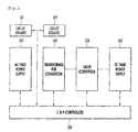
- FIG. 1 is a schematic block diagram of an HVDC system.
- the HVDC system may include an alternating current (AC) side power supply 102, a transformer for conversion 103, a valve (converter) 104, a DC side power supply 105, a circuit breaker 101, and a controller (control and protection; C&P) 106.
- AC alternating current
- C&P controller
- the controller 106 is a system for monitoring and protecting a controller for each function that is used in the HVDC system, and immediately deals with malfunction to protect the system when a specific controller malfunctions.
- the controller 106 may control the above-described components as a whole.
- the same two systems may be provided so that systems performing the same function in the HVDC system continuously perform an operation. That is, there are a first system and a second system, in which case when the currently operating system has a trouble, such as system malfunction while providing a service, a standby spare system or another system that is providing a service may continue to provide the service.
- each of the two systems in the HVDC system has an active mode and a standby mode, respectively, and the two systems are logically combined to operate, monitoring each other.
- the currently operating system is called the active system and a system being in a standby state is called the standby system.
- the active system is actually operating and in an active state in a system, performs the input and output operations of all connected devices and the logic of all connected devices, and provides all operation information to the standby system that is in a standby state.
- the standby system waits in a ready state to become the active system, i.e., in an inactive state, and is ready to immediately change to the active state through synchronization of all data and state information in the active system.
- each of the two systems in the HVDC system may have the active mode and monitor the state of a counterpart system while operating, and when one system has a trouble, another system may continue to provide a service.
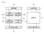
- Figs. 2 and 3 are diagrams for explaining the redundant control device and method of an HVDC transmission system according to an embodiment.
- the redundant control device includes a first system 10, a second system 20, a first change over logic (COL) 20 and a second COL 21.
- the COL is a device that determines whether to switch control in a control system that has a redundant configuration.
- the first COL 11 controls a first control module 31, and the second COL 21 controls a second control module 32.
- a first system 10, a second system 20, the first COL 11, and the second COL 21 may be the redundant control device that is a component of the controller 106 in FIG. 1
- the first control module 31 and the second control module 32 may be valve controllers that are components of the valve 104.
- the first COL 11 transmits a control command to the first control module 31, and the second COL 21 transmits a control command to the second control module 32.
- the first COL 11 transmits its operation state and the operation state of the first system 10 to the second COL 21, and on the contrary, the second COL 21 transmits its operation state and the operation state of the second system 20 to the first COL 11.
- the first COL 11 includes a system control unit 111, a monitoring unit 112, a command control unit 113, and a COL control unit 114.
Landscapes
- Engineering & Computer Science (AREA)
- Power Engineering (AREA)
- Physics & Mathematics (AREA)
- General Physics & Mathematics (AREA)
- Automation & Control Theory (AREA)
- Electromagnetism (AREA)
- Optical Communication System (AREA)
- Supply And Distribution Of Alternating Current (AREA)
- Direct Current Feeding And Distribution (AREA)
- Hardware Redundancy (AREA)
Abstract
Description
- The present disclosure relates to a redundant control device and method, and more particularly, to a redundant control device and method of a high voltage direct current (HVDC) transmission system.
- There are two power system interconnection methods, a typical one for interconnecting AC power systems as they are, and the other for interconnecting systems after converting AC power into DC power through a power converter. In recent, an interest in the method of interconnecting power systems after converting the AC power into the DC power is more increasing than the method of interconnecting AC power systems as they are. A high voltage direct current (HVDC) transmission system using a power converter is also installed between Jeju-island and Haenam-gun in Korea to interconnect power systems between Jeju-island and Haenam-gun.
- An HVDC transmission method indicates a power supply method in which AC power generated at the power station is converted into DC power, and the DC power is transmitted and then re-converted into AC power in a power receiving region.
- The DC transmission method has many advantages.
- Firstly, since the size of a DC voltage is just about 70% of the maximum value of an AC voltage, the HVDC transmission system may easily perform device insulation and since its voltage is low, it is possible to reduce the number of insulators installed in each device and the height of an iron tower.
- Since the DC method has less transmission loss than an AC method when the same power is transmitted, the best advantage of the HVDC transmission system is that power transmission efficiency may increase. The HDVC transmission system may transmit currents twice or more in the DC method than the AC method.
- Since the HVDC transmission system may reduce wire consumption and the area of a transmission line, it is effective and also possible to enhance the stability of systems by connecting two systems having different voltages or frequencies.
- The HVDC transmission system has no constraint on a power transmission distance and the DC transmission method needs inexpensive construction costs in land power transmission exceeding 450 Km or in submarine power transmission exceeding 40 Km as well.
- Thus, the HVDC transmission system is used for a power system interconnection method of new renewable energy, especially for power transmission of a large offshore wind farm.
- Since the distance between a power station and an electricity user in China and India is 1000 Km or longer, the prevalence of the HVDC transmission system is rapidly increasing recently.
- Since a stable operation is very important to such an HVDC system, related facilities, such as a control of the HVDC have a redundant configuration.
- Two systems that have a redundant configuration are typically connected through a SCSI cable, in which case a problem with disconnection or wiring occurs.
- Also, there is a limitation in that a voltage for checking the operation of a counterpart system is affected by noise and thus a redundant control device malfunctions.
- Embodiments provide a redundant control device of a high voltage direct current (HVDC) transmission system that has a new structure.
- Embodiments provide a redundant control device of an HVDC transmission system that that may transmit data reliably.
- In one embodiment, a redundant control device of a high voltage direct current (HVDC) transmission system includes a first system and a second system that performs a function corresponding to that of the first system; and a first change over logic (COL) and a second COL that determine whether to switch between the first system and the system, wherein there are optical communication modules between the first system and the first COL, between the first COL and the second COL, and between the second system and the second COL to transmit and receive data, and the first COL and the second COL includes a monitoring control unit that checks a connection or wiring state of the optical communication modules and validity of transmission data.
- An Embodiment has an advantage in that it is possible to provide a redundant control device of a high voltage direct current (HVDC) transmission system that has a new structure.
- An embodiment has an advantage in that it is possible to provide a redundant control device of an HVDC transmission system that that may transmit data reliably.
- The details of one or more embodiments are set forth in the accompanying drawings and the description below. Other features will be apparent from the description and drawings, and from the claims.
-
-
Fig. 1 is a schematic block diagram of a high voltage direct current (HVDC) transmission system. -
Figs. 2 and3 are diagrams for explaining the redundant control device and method of an HVDC transmission system according to an embodiment. - Reference will now be made in detail to the embodiments of the present disclosure, examples of which are illustrated in the accompanying drawings.
- An electric device for an electric vehicle according to an embodiment will be described in detail with reference to the accompanying drawings. The invention may, however, be embodied in many different forms and should not be construed as being limited to the embodiments set forth herein; rather, that alternate embodiments included in other retrogressive inventions or falling within the spirit and scope of the present disclosure can easily be derived through adding, altering, and changing, and will fully convey the concept of the invention to those skilled in the art.
- When it is mentioned that any component is "connected" or "accessed" to another component, it should be understood that the former can be directly connected to the latter, or there may be another component in between. On the contrary, when any component is referred to as being 'directly connected' or 'directly accessed' to another component, it should be understood that there may be no other component in between.
- The terms used in the present application are used only to describe specific embodiments and are not intended to limit the present disclosure. The terms in singular form include the plural form unless otherwise specified. It should be understood that the term "includes" or "has" indicates the presence of characteristics, numbers, steps, operations, components, parts or combinations thereof represented in the present disclosure but do not exclude the presence or addition of one or more other characteristics, numbers, steps, operations, components, parts or combinations thereof. Also, the term "... unit" in the present disclosure means a unit for processing at least one function or operation, and it may be implanted in hardware, software or a combination thereof.
- In the following, the redundant control device and method of a high voltage direct current (HVDC) transmission system according to the present disclosure are described in detail with reference to
Figs. 1 to 3 . -
FIG. 1 is a schematic block diagram of an HVDC system. - Referring to
Fig. 1 , the HVDC system may include an alternating current (AC)side power supply 102, a transformer forconversion 103, a valve (converter) 104, a DCside power supply 105, acircuit breaker 101, and a controller (control and protection; C&P) 106. - The
controller 106 is a system for monitoring and protecting a controller for each function that is used in the HVDC system, and immediately deals with malfunction to protect the system when a specific controller malfunctions. Thecontroller 106 may control the above-described components as a whole. - The same two systems may be provided so that systems performing the same function in the HVDC system continuously perform an operation. That is, there are a first system and a second system, in which case when the currently operating system has a trouble, such as system malfunction while providing a service, a standby spare system or another system that is providing a service may continue to provide the service.
- In this case, each of the two systems in the HVDC system has an active mode and a standby mode, respectively, and the two systems are logically combined to operate, monitoring each other. The currently operating system is called the active system and a system being in a standby state is called the standby system. The active system is actually operating and in an active state in a system, performs the input and output operations of all connected devices and the logic of all connected devices, and provides all operation information to the standby system that is in a standby state. The standby system waits in a ready state to become the active system, i.e., in an inactive state, and is ready to immediately change to the active state through synchronization of all data and state information in the active system.
- Also, each of the two systems in the HVDC system may have the active mode and monitor the state of a counterpart system while operating, and when one system has a trouble, another system may continue to provide a service.
-
Figs. 2 and3 are diagrams for explaining the redundant control device and method of an HVDC transmission system according to an embodiment. - Referring to
Figs. 2 and3 , the redundant control device according to an embodiment includes afirst system 10, asecond system 20, a first change over logic (COL) 20 and asecond COL 21. In this example, the COL is a device that determines whether to switch control in a control system that has a redundant configuration. - The
first COL 11 controls afirst control module 31, and thesecond COL 21 controls asecond control module 32. - A
first system 10, asecond system 20, thefirst COL 11, and thesecond COL 21 may be the redundant control device that is a component of thecontroller 106 inFIG. 1 , and thefirst control module 31 and thesecond control module 32 may be valve controllers that are components of thevalve 104. - The
first COL 11 transmits a control command to thefirst control module 31, and thesecond COL 21 transmits a control command to thesecond control module 32. - Also, the
first COL 11 transmits its operation state and the operation state of thefirst system 10 to thesecond COL 21, and on the contrary, thesecond COL 21 transmits its operation state and the operation state of thesecond system 20 to thefirst COL 11. - Also, the
first COL 11 transmits its operation state and the operation states of thesecond system 20 and thesecond COL 21 to thefirst system 10. - Also, the
second COL 21 transmits its operation state and the operation states of thefirst system 10 and thefirst COL 11 to thesecond system 20. - In the HVDC transmission system as described above, when the
first system 10 has a trouble, thefirst COL 11 senses the trouble, inhibits thefirst control module 31 from becoming controlled by thefirst COL 11, and also passes a control right to thesecond COL 21 and thesecond system 20 to enable thefirst control module 31 to be controlled by thesecond system 20. - In the HVDC transmission system, when the
second system 20 has a trouble, thesecond COL 21 senses the trouble, inhibits thesecond control module 32 from becoming controlled by thesecond COL 21, and also passes a control right to thefirst COL 11 and thefirst system 10 to enable thesecond control module 32 to be controlled by thefirst system 10. - In the HVDC transmission system as described above, there are optical communication modules between the
first system 10 and thefirst COL 11, between thefirst COL 11 and thefirst control module 31, between thefirst COL 11 and thesecond COL 21, between thesecond system 20 and thesecond COL 21, and between thesecond COL 21 and thesecond control module 32 to transmit and receive data without using typical SCSI cables. - In the case that the optical communication module is used, data validity and real-time property may be improved five times or more than when using the SCSI cable, and it is possible to minimize malfunction due to external noise.
-
FIG. 3 illustrates the detailed structure of thefirst COL 11. Although the structure of thesecond COL 21 is not shown, it is the same as that of thefirst COL 11. - As shown in
FIG. 3 , thefirst COL 11 includes asystem control unit 111, amonitoring unit 112, acommand control unit 113, and aCOL control unit 114. - The
system control unit 111 checks the current states of thefirst system 10 and thefirst COL 11 and delivers a command to stop their operations when malfunction is found, theCOL control unit 114 exchanges data between the COLs, checks whether there is an error, and transmits the current states of thefirst system 10 and thefirst COL 11 to a counterpart COL control unit (the COL control unit of the second COL), and thecommand control unit 113 delivers a control command to thefirst control module 31 according to the state of thefirst COL 11. - Also, the
monitoring unit 112 checks the connection or wiring state of the optical communication modules and the validity of transmission data in real time to deliver them to thesystem control unit 111. Accordingly, thefirst system 10 may accurately set a right and update state information. - As discussed above, since the redundant control device of the HVDC transmission system transmits and receives data through optical communication modules and monitors the connection or wiring state of the optical communication modules and the validity of transmission data in real time, there is an advantage in that it is possible to transmit and receive data reliably.
- Each component and/or function described in various embodiments above may be combined each other, and a person skilled in the art may understand that various modifications and changes may be implemented without departing from the spirit and scope of the present disclosure set forth in the following claims.
Claims (4)
- A redundant control device of a high voltage direct current (HVDC) transmission system, the redundant control device comprising:a first system (10) and a second system (20) that performs a function corresponding to that of the first system (10); anda first change over logic (COL) (11) and a second COL (21) that determine whether to switch between the first system (10) and the system (20),wherein there are optical communication modules between the first system (10) and the first COL (11), between the first COL (11) and the second COL (21), and between the second system (20) and the second COL (21) to transmit and receive data, andthe first COL (11) and the second COL (21) comprise a monitoring control unit (112) that checks a connection or wiring state of the optical communication modules and validity of transmission data.
- The redundant control device according to claim 1, wherein the first COL (11) controls the first control module (31), the second COL (21) controls the second control module (32), and according to states of the first system (10) and the second system (20), the first COL (11) controls the first control module (31) and the second control module (32) or the second COL (21) controls the first control module (31) or the second control module (32).
- The redundancy control device according to claim 2, wherein the first COL (11) comprises a system control unit that checks current states of the first system (10) and the first COL (11) and delivers a command to stop their operations when malfunction is found, a COL control unit (114) that exchanges data with the second COL (21), checks whether there is an error, and transmits current states of the first system (10) and the first COL (11) to the second COL (21), and a command control unit (113) that delivers a control command to the first control module (31) according to a state of the first COL (11).
- The redundant control device according to claim 2, wherein there are optical communication modules between the first COL (11) and the first control module (31) and between the second COL (21) and the second control module (32) to transmit and receive data.
Applications Claiming Priority (1)
| Application Number | Priority Date | Filing Date | Title |
|---|---|---|---|
| KR1020150033379A KR101769664B1 (en) | 2015-03-10 | 2015-03-10 | Redundant controller of hvdc system |
Publications (2)
| Publication Number | Publication Date |
|---|---|
| EP3067760A1 true EP3067760A1 (en) | 2016-09-14 |
| EP3067760B1 EP3067760B1 (en) | 2020-07-22 |
Family
ID=55405143
Family Applications (1)
| Application Number | Title | Priority Date | Filing Date |
|---|---|---|---|
| EP16155827.5A Active EP3067760B1 (en) | 2015-03-10 | 2016-02-16 | Redundant control device and method of hvdc system |
Country Status (6)
| Country | Link |
|---|---|
| US (1) | US10122291B2 (en) |
| EP (1) | EP3067760B1 (en) |
| JP (1) | JP6240238B2 (en) |
| KR (1) | KR101769664B1 (en) |
| CN (1) | CN105978045B (en) |
| ES (1) | ES2822205T3 (en) |
Cited By (1)
| Publication number | Priority date | Publication date | Assignee | Title |
|---|---|---|---|---|
| CN110086211A (en) * | 2019-05-06 | 2019-08-02 | 国家电网公司东北分部 | High frequency centralized control method suitable for extensive AC-DC hybrid power grid |
Families Citing this family (5)
| Publication number | Priority date | Publication date | Assignee | Title |
|---|---|---|---|---|
| EP3336624B1 (en) * | 2016-12-19 | 2019-02-06 | Siemens Aktiengesellschaft | Arrangement with two redundant boards which monitor each other |
| CN108923530A (en) * | 2018-05-23 | 2018-11-30 | 国网上海市电力公司 | A kind of double set redundancy switching methods of transformer station measurement and control device |
| CN109407505B (en) * | 2018-10-25 | 2022-12-02 | 许继电气股份有限公司 | Redundancy measurement control system of direct current transmission valve bank and outlet control method and device thereof |
| CN111181190B (en) * | 2020-01-15 | 2021-12-24 | 许继集团有限公司 | Direct-current converter valve control system and switching control method and device thereof |
| CN114043996A (en) | 2020-05-20 | 2022-02-15 | 华为技术有限公司 | Redundant electronic control system and equipment |
Citations (2)
| Publication number | Priority date | Publication date | Assignee | Title |
|---|---|---|---|---|
| US4672529A (en) * | 1984-10-26 | 1987-06-09 | Autech Partners Ltd. | Self contained data acquisition apparatus and system |
| EP2822145A1 (en) * | 2013-03-06 | 2015-01-07 | Huawei Technologies Co., Ltd. | Power supply method and power supply apparatus |
Family Cites Families (16)
| Publication number | Priority date | Publication date | Assignee | Title |
|---|---|---|---|---|
| JPH04150776A (en) | 1990-10-12 | 1992-05-25 | Toshiba Corp | Bypass pair control circuit for thyristor bridge |
| JP2894645B2 (en) | 1991-06-21 | 1999-05-24 | 株式会社東芝 | Control device of AC / DC converter |
| JPH05347588A (en) | 1992-06-15 | 1993-12-27 | Nec Corp | Monitoring system for connection of optical transmission line |
| JP3328365B2 (en) | 1993-04-19 | 2002-09-24 | 東京電力株式会社 | Islanding detection device |
| US7460347B2 (en) * | 2001-07-06 | 2008-12-02 | Schweitzer Engineering Laboratories, Inc. | Systems and methods for performing a redundancy check using intelligent electronic devices in an electric power system |
| KR100412301B1 (en) | 2002-03-13 | 2003-12-31 | 한국전기연구원 | Dual control method in hierarchical control system and apparatus thereof |
| US7126800B2 (en) * | 2003-07-11 | 2006-10-24 | General Electric Company | Method and system for communications channel delay asymmetry compensation using global positioning systems |
| KR100564758B1 (en) | 2003-12-12 | 2006-03-27 | 한국전자통신연구원 | Communication path redundancy device and operation method of redundant communication path |
| DE112005003661A5 (en) | 2005-06-02 | 2008-05-21 | Siemens Aktiengesellschaft | Device for detecting and processing a plurality of measured values in an HVDC system |
| KR100901319B1 (en) | 2007-09-27 | 2009-06-09 | 한국전력공사 | Power distribution system and method |
| CN102075068B (en) | 2009-11-24 | 2015-01-28 | 通用电气公司 | Circuit and topology for high-reliability power electronic device system |
| KR20130020504A (en) | 2011-08-19 | 2013-02-27 | 주식회사 케이티 | Duplicated high voltage direct current power feeding apparatus and its method |
| KR101713353B1 (en) | 2012-03-06 | 2017-03-07 | 엘에스산전 주식회사 | Redundant controller system |
| KR101724767B1 (en) | 2012-04-13 | 2017-04-07 | 엘에스산전 주식회사 | Redundancy control apparatus for hvdc system |
| JP5949255B2 (en) * | 2012-07-18 | 2016-07-06 | 富士通株式会社 | Communication control apparatus and communication control method |
| KR101442818B1 (en) | 2012-12-28 | 2014-09-24 | 주식회사 효성 | Dual controller and method for outputting control signal of the same |
-
2015
- 2015-03-10 KR KR1020150033379A patent/KR101769664B1/en active Active
-
2016
- 2016-02-16 EP EP16155827.5A patent/EP3067760B1/en active Active
- 2016-02-16 ES ES16155827T patent/ES2822205T3/en active Active
- 2016-03-01 US US15/057,353 patent/US10122291B2/en active Active
- 2016-03-02 JP JP2016040304A patent/JP6240238B2/en active Active
- 2016-03-09 CN CN201610133087.9A patent/CN105978045B/en active Active
Patent Citations (2)
| Publication number | Priority date | Publication date | Assignee | Title |
|---|---|---|---|---|
| US4672529A (en) * | 1984-10-26 | 1987-06-09 | Autech Partners Ltd. | Self contained data acquisition apparatus and system |
| EP2822145A1 (en) * | 2013-03-06 | 2015-01-07 | Huawei Technologies Co., Ltd. | Power supply method and power supply apparatus |
Cited By (2)
| Publication number | Priority date | Publication date | Assignee | Title |
|---|---|---|---|---|
| CN110086211A (en) * | 2019-05-06 | 2019-08-02 | 国家电网公司东北分部 | High frequency centralized control method suitable for extensive AC-DC hybrid power grid |
| CN110086211B (en) * | 2019-05-06 | 2021-04-30 | 国家电网公司东北分部 | High-frequency centralized control method suitable for large-scale alternating current-direct current hybrid power grid |
Also Published As
| Publication number | Publication date |
|---|---|
| CN105978045A (en) | 2016-09-28 |
| KR101769664B1 (en) | 2017-08-18 |
| KR20160109272A (en) | 2016-09-21 |
| US20160268914A1 (en) | 2016-09-15 |
| EP3067760B1 (en) | 2020-07-22 |
| ES2822205T3 (en) | 2021-04-29 |
| CN105978045B (en) | 2019-06-11 |
| JP6240238B2 (en) | 2017-11-29 |
| US10122291B2 (en) | 2018-11-06 |
| JP2016167969A (en) | 2016-09-15 |
Similar Documents
| Publication | Publication Date | Title |
|---|---|---|
| EP3067760B1 (en) | Redundant control device and method of hvdc system | |
| EP3264550B1 (en) | Access control method for parallel direct current power supplies and device thereof | |
| WO2015087638A1 (en) | Solar photovoltaic system | |
| US20090196077A1 (en) | Energy management system and control method using the same | |
| CN114070093B (en) | Multi-module power supply system for submarine observation network based on HVDC conversion technology | |
| CN110649645B (en) | Quick shutdown device and its applicable photovoltaic power generation system | |
| US9419428B2 (en) | Protection device for DC collection systems | |
| KR20210094630A (en) | Flexible connection substation and control method | |
| US20200295557A1 (en) | Control system for and method of fault location, isolation and supply restoration | |
| CN103825363B (en) | A kind of wind-light storage low pressure micro-capacitance sensor group protection coordination controller | |
| EP2830200B1 (en) | A power converter | |
| CN107086553A (en) | A control and protection method and system for a direct current transmission system | |
| CN108899911B (en) | Direct current power transformation system | |
| JP6856303B2 (en) | DC power transmission equipment | |
| EP4462699A1 (en) | Power supply method and apparatus, storage medium, and program product | |
| CN110556794B (en) | Bus bar protection configuration method of multi-end hybrid direct current system | |
| CN204069002U (en) | Based on number, the electric simultaneous interpretation device of insulate line remote auto power supply technique | |
| JP6097148B2 (en) | Power conditioner and distributed system including the power conditioner | |
| JP6612990B2 (en) | Power converter | |
| CN107069736A (en) | For the urgent Poewr control method of AC/DC Hybrid Transmission System containing flexible direct current | |
| EP4579981A1 (en) | Photovoltaic power supply system and backup box | |
| CN104330707A (en) | Island detection system and island detection method | |
| KR102638518B1 (en) | Integrated control apparatus of dc transmission network and method thereof | |
| CN216215898U (en) | Highway direct current remote power supply system | |
| EP2933892B1 (en) | Changeover method of hvdc transmission system |
Legal Events
| Date | Code | Title | Description |
|---|---|---|---|
| PUAI | Public reference made under article 153(3) epc to a published international application that has entered the european phase |
Free format text: ORIGINAL CODE: 0009012 |
|
| AK | Designated contracting states |
Kind code of ref document: A1 Designated state(s): AL AT BE BG CH CY CZ DE DK EE ES FI FR GB GR HR HU IE IS IT LI LT LU LV MC MK MT NL NO PL PT RO RS SE SI SK SM TR |
|
| AX | Request for extension of the european patent |
Extension state: BA ME |
|
| STAA | Information on the status of an ep patent application or granted ep patent |
Free format text: STATUS: REQUEST FOR EXAMINATION WAS MADE |
|
| 17P | Request for examination filed |
Effective date: 20161109 |
|
| RBV | Designated contracting states (corrected) |
Designated state(s): AL AT BE BG CH CY CZ DE DK EE ES FI FR GB GR HR HU IE IS IT LI LT LU LV MC MK MT NL NO PL PT RO RS SE SI SK SM TR |
|
| STAA | Information on the status of an ep patent application or granted ep patent |
Free format text: STATUS: EXAMINATION IS IN PROGRESS |
|
| 17Q | First examination report despatched |
Effective date: 20191107 |
|
| GRAP | Despatch of communication of intention to grant a patent |
Free format text: ORIGINAL CODE: EPIDOSNIGR1 |
|
| STAA | Information on the status of an ep patent application or granted ep patent |
Free format text: STATUS: GRANT OF PATENT IS INTENDED |
|
| INTG | Intention to grant announced |
Effective date: 20200504 |
|
| RIN1 | Information on inventor provided before grant (corrected) |
Inventor name: KIM, JONG BAE Inventor name: LEE, SEUNG HUN Inventor name: KIM, EUNG SOO |
|
| GRAS | Grant fee paid |
Free format text: ORIGINAL CODE: EPIDOSNIGR3 |
|
| GRAA | (expected) grant |
Free format text: ORIGINAL CODE: 0009210 |
|
| STAA | Information on the status of an ep patent application or granted ep patent |
Free format text: STATUS: THE PATENT HAS BEEN GRANTED |
|
| AK | Designated contracting states |
Kind code of ref document: B1 Designated state(s): AL AT BE BG CH CY CZ DE DK EE ES FI FR GB GR HR HU IE IS IT LI LT LU LV MC MK MT NL NO PL PT RO RS SE SI SK SM TR |
|
| REG | Reference to a national code |
Ref country code: GB Ref legal event code: FG4D |
|
| REG | Reference to a national code |
Ref country code: CH Ref legal event code: EP |
|
| REG | Reference to a national code |
Ref country code: DE Ref legal event code: R096 Ref document number: 602016040257 Country of ref document: DE |
|
| REG | Reference to a national code |
Ref country code: AT Ref legal event code: REF Ref document number: 1293987 Country of ref document: AT Kind code of ref document: T Effective date: 20200815 |
|
| REG | Reference to a national code |
Ref country code: IE Ref legal event code: FG4D |
|
| REG | Reference to a national code |
Ref country code: LT Ref legal event code: MG4D |
|
| REG | Reference to a national code |
Ref country code: AT Ref legal event code: MK05 Ref document number: 1293987 Country of ref document: AT Kind code of ref document: T Effective date: 20200722 |
|
| PG25 | Lapsed in a contracting state [announced via postgrant information from national office to epo] |
Ref country code: SE Free format text: LAPSE BECAUSE OF FAILURE TO SUBMIT A TRANSLATION OF THE DESCRIPTION OR TO PAY THE FEE WITHIN THE PRESCRIBED TIME-LIMIT Effective date: 20200722 Ref country code: FI Free format text: LAPSE BECAUSE OF FAILURE TO SUBMIT A TRANSLATION OF THE DESCRIPTION OR TO PAY THE FEE WITHIN THE PRESCRIBED TIME-LIMIT Effective date: 20200722 Ref country code: BG Free format text: LAPSE BECAUSE OF FAILURE TO SUBMIT A TRANSLATION OF THE DESCRIPTION OR TO PAY THE FEE WITHIN THE PRESCRIBED TIME-LIMIT Effective date: 20201022 Ref country code: GR Free format text: LAPSE BECAUSE OF FAILURE TO SUBMIT A TRANSLATION OF THE DESCRIPTION OR TO PAY THE FEE WITHIN THE PRESCRIBED TIME-LIMIT Effective date: 20201023 Ref country code: LT Free format text: LAPSE BECAUSE OF FAILURE TO SUBMIT A TRANSLATION OF THE DESCRIPTION OR TO PAY THE FEE WITHIN THE PRESCRIBED TIME-LIMIT Effective date: 20200722 Ref country code: NO Free format text: LAPSE BECAUSE OF FAILURE TO SUBMIT A TRANSLATION OF THE DESCRIPTION OR TO PAY THE FEE WITHIN THE PRESCRIBED TIME-LIMIT Effective date: 20201022 Ref country code: HR Free format text: LAPSE BECAUSE OF FAILURE TO SUBMIT A TRANSLATION OF THE DESCRIPTION OR TO PAY THE FEE WITHIN THE PRESCRIBED TIME-LIMIT Effective date: 20200722 Ref country code: PT Free format text: LAPSE BECAUSE OF FAILURE TO SUBMIT A TRANSLATION OF THE DESCRIPTION OR TO PAY THE FEE WITHIN THE PRESCRIBED TIME-LIMIT Effective date: 20201123 Ref country code: AT Free format text: LAPSE BECAUSE OF FAILURE TO SUBMIT A TRANSLATION OF THE DESCRIPTION OR TO PAY THE FEE WITHIN THE PRESCRIBED TIME-LIMIT Effective date: 20200722 |
|
| PG25 | Lapsed in a contracting state [announced via postgrant information from national office to epo] |
Ref country code: IS Free format text: LAPSE BECAUSE OF FAILURE TO SUBMIT A TRANSLATION OF THE DESCRIPTION OR TO PAY THE FEE WITHIN THE PRESCRIBED TIME-LIMIT Effective date: 20201122 Ref country code: PL Free format text: LAPSE BECAUSE OF FAILURE TO SUBMIT A TRANSLATION OF THE DESCRIPTION OR TO PAY THE FEE WITHIN THE PRESCRIBED TIME-LIMIT Effective date: 20200722 Ref country code: RS Free format text: LAPSE BECAUSE OF FAILURE TO SUBMIT A TRANSLATION OF THE DESCRIPTION OR TO PAY THE FEE WITHIN THE PRESCRIBED TIME-LIMIT Effective date: 20200722 Ref country code: LV Free format text: LAPSE BECAUSE OF FAILURE TO SUBMIT A TRANSLATION OF THE DESCRIPTION OR TO PAY THE FEE WITHIN THE PRESCRIBED TIME-LIMIT Effective date: 20200722 |
|
| PG25 | Lapsed in a contracting state [announced via postgrant information from national office to epo] |
Ref country code: NL Free format text: LAPSE BECAUSE OF FAILURE TO SUBMIT A TRANSLATION OF THE DESCRIPTION OR TO PAY THE FEE WITHIN THE PRESCRIBED TIME-LIMIT Effective date: 20200722 |
|
| REG | Reference to a national code |
Ref country code: DE Ref legal event code: R097 Ref document number: 602016040257 Country of ref document: DE |
|
| PG25 | Lapsed in a contracting state [announced via postgrant information from national office to epo] |
Ref country code: RO Free format text: LAPSE BECAUSE OF FAILURE TO SUBMIT A TRANSLATION OF THE DESCRIPTION OR TO PAY THE FEE WITHIN THE PRESCRIBED TIME-LIMIT Effective date: 20200722 Ref country code: SM Free format text: LAPSE BECAUSE OF FAILURE TO SUBMIT A TRANSLATION OF THE DESCRIPTION OR TO PAY THE FEE WITHIN THE PRESCRIBED TIME-LIMIT Effective date: 20200722 Ref country code: EE Free format text: LAPSE BECAUSE OF FAILURE TO SUBMIT A TRANSLATION OF THE DESCRIPTION OR TO PAY THE FEE WITHIN THE PRESCRIBED TIME-LIMIT Effective date: 20200722 Ref country code: DK Free format text: LAPSE BECAUSE OF FAILURE TO SUBMIT A TRANSLATION OF THE DESCRIPTION OR TO PAY THE FEE WITHIN THE PRESCRIBED TIME-LIMIT Effective date: 20200722 Ref country code: CZ Free format text: LAPSE BECAUSE OF FAILURE TO SUBMIT A TRANSLATION OF THE DESCRIPTION OR TO PAY THE FEE WITHIN THE PRESCRIBED TIME-LIMIT Effective date: 20200722 |
|
| PLBE | No opposition filed within time limit |
Free format text: ORIGINAL CODE: 0009261 |
|
| STAA | Information on the status of an ep patent application or granted ep patent |
Free format text: STATUS: NO OPPOSITION FILED WITHIN TIME LIMIT |
|
| PG25 | Lapsed in a contracting state [announced via postgrant information from national office to epo] |
Ref country code: AL Free format text: LAPSE BECAUSE OF FAILURE TO SUBMIT A TRANSLATION OF THE DESCRIPTION OR TO PAY THE FEE WITHIN THE PRESCRIBED TIME-LIMIT Effective date: 20200722 |
|
| 26N | No opposition filed |
Effective date: 20210423 |
|
| PG25 | Lapsed in a contracting state [announced via postgrant information from national office to epo] |
Ref country code: SK Free format text: LAPSE BECAUSE OF FAILURE TO SUBMIT A TRANSLATION OF THE DESCRIPTION OR TO PAY THE FEE WITHIN THE PRESCRIBED TIME-LIMIT Effective date: 20200722 |
|
| PG25 | Lapsed in a contracting state [announced via postgrant information from national office to epo] |
Ref country code: SI Free format text: LAPSE BECAUSE OF FAILURE TO SUBMIT A TRANSLATION OF THE DESCRIPTION OR TO PAY THE FEE WITHIN THE PRESCRIBED TIME-LIMIT Effective date: 20200722 |
|
| PG25 | Lapsed in a contracting state [announced via postgrant information from national office to epo] |
Ref country code: MC Free format text: LAPSE BECAUSE OF FAILURE TO SUBMIT A TRANSLATION OF THE DESCRIPTION OR TO PAY THE FEE WITHIN THE PRESCRIBED TIME-LIMIT Effective date: 20200722 |
|
| REG | Reference to a national code |
Ref country code: NL Ref legal event code: MP Effective date: 20200722 |
|
| REG | Reference to a national code |
Ref country code: BE Ref legal event code: MM Effective date: 20210228 |
|
| PG25 | Lapsed in a contracting state [announced via postgrant information from national office to epo] |
Ref country code: LU Free format text: LAPSE BECAUSE OF NON-PAYMENT OF DUE FEES Effective date: 20210216 Ref country code: LI Free format text: LAPSE BECAUSE OF NON-PAYMENT OF DUE FEES Effective date: 20210228 Ref country code: CH Free format text: LAPSE BECAUSE OF NON-PAYMENT OF DUE FEES Effective date: 20210228 |
|
| PG25 | Lapsed in a contracting state [announced via postgrant information from national office to epo] |
Ref country code: IE Free format text: LAPSE BECAUSE OF NON-PAYMENT OF DUE FEES Effective date: 20210216 |
|
| PG25 | Lapsed in a contracting state [announced via postgrant information from national office to epo] |
Ref country code: BE Free format text: LAPSE BECAUSE OF NON-PAYMENT OF DUE FEES Effective date: 20210228 |
|
| PG25 | Lapsed in a contracting state [announced via postgrant information from national office to epo] |
Ref country code: HU Free format text: LAPSE BECAUSE OF FAILURE TO SUBMIT A TRANSLATION OF THE DESCRIPTION OR TO PAY THE FEE WITHIN THE PRESCRIBED TIME-LIMIT; INVALID AB INITIO Effective date: 20160216 |
|
| PG25 | Lapsed in a contracting state [announced via postgrant information from national office to epo] |
Ref country code: CY Free format text: LAPSE BECAUSE OF FAILURE TO SUBMIT A TRANSLATION OF THE DESCRIPTION OR TO PAY THE FEE WITHIN THE PRESCRIBED TIME-LIMIT Effective date: 20200722 |
|
| P01 | Opt-out of the competence of the unified patent court (upc) registered |
Effective date: 20230625 |
|
| PG25 | Lapsed in a contracting state [announced via postgrant information from national office to epo] |
Ref country code: MK Free format text: LAPSE BECAUSE OF FAILURE TO SUBMIT A TRANSLATION OF THE DESCRIPTION OR TO PAY THE FEE WITHIN THE PRESCRIBED TIME-LIMIT Effective date: 20200722 |
|
| PG25 | Lapsed in a contracting state [announced via postgrant information from national office to epo] |
Ref country code: TR Free format text: LAPSE BECAUSE OF FAILURE TO SUBMIT A TRANSLATION OF THE DESCRIPTION OR TO PAY THE FEE WITHIN THE PRESCRIBED TIME-LIMIT Effective date: 20200722 |
|
| PG25 | Lapsed in a contracting state [announced via postgrant information from national office to epo] |
Ref country code: MT Free format text: LAPSE BECAUSE OF FAILURE TO SUBMIT A TRANSLATION OF THE DESCRIPTION OR TO PAY THE FEE WITHIN THE PRESCRIBED TIME-LIMIT Effective date: 20200722 |
|
| PGFP | Annual fee paid to national office [announced via postgrant information from national office to epo] |
Ref country code: GB Payment date: 20251208 Year of fee payment: 11 |
|
| PGFP | Annual fee paid to national office [announced via postgrant information from national office to epo] |
Ref country code: FR Payment date: 20251209 Year of fee payment: 11 |
|
| PGFP | Annual fee paid to national office [announced via postgrant information from national office to epo] |
Ref country code: ES Payment date: 20260324 Year of fee payment: 11 |
|
| PGFP | Annual fee paid to national office [announced via postgrant information from national office to epo] |
Ref country code: DE Payment date: 20251208 Year of fee payment: 11 |
|
| PGFP | Annual fee paid to national office [announced via postgrant information from national office to epo] |
Ref country code: IT Payment date: 20251209 Year of fee payment: 11 |