EP3067622B1 - Brennkammer mit doppelwand und verahren zur kühlung der brennkammer - Google Patents
Brennkammer mit doppelwand und verahren zur kühlung der brennkammer Download PDFInfo
- Publication number
- EP3067622B1 EP3067622B1 EP15158820.9A EP15158820A EP3067622B1 EP 3067622 B1 EP3067622 B1 EP 3067622B1 EP 15158820 A EP15158820 A EP 15158820A EP 3067622 B1 EP3067622 B1 EP 3067622B1
- Authority
- EP
- European Patent Office
- Prior art keywords
- cooling
- cavity
- wall
- duct wall
- gas
- Prior art date
- Legal status (The legal status is an assumption and is not a legal conclusion. Google has not performed a legal analysis and makes no representation as to the accuracy of the status listed.)
- Active
Links
- 238000001816 cooling Methods 0.000 title claims description 119
- 238000002485 combustion reaction Methods 0.000 title claims description 109
- 238000000034 method Methods 0.000 title claims description 10
- 239000007789 gas Substances 0.000 claims description 99
- 239000000112 cooling gas Substances 0.000 claims description 70
- 238000010276 construction Methods 0.000 claims description 11
- 239000012809 cooling fluid Substances 0.000 claims description 2
- 238000011144 upstream manufacturing Methods 0.000 description 8
- 239000000446 fuel Substances 0.000 description 6
- CURLTUGMZLYLDI-UHFFFAOYSA-N Carbon dioxide Chemical compound O=C=O CURLTUGMZLYLDI-UHFFFAOYSA-N 0.000 description 4
- 239000000567 combustion gas Substances 0.000 description 3
- 229910002092 carbon dioxide Inorganic materials 0.000 description 2
- 239000001569 carbon dioxide Substances 0.000 description 2
- 230000008859 change Effects 0.000 description 2
- 238000010790 dilution Methods 0.000 description 2
- 239000012895 dilution Substances 0.000 description 2
- 239000003546 flue gas Substances 0.000 description 2
- 239000000463 material Substances 0.000 description 2
- 239000002184 metal Substances 0.000 description 2
- 239000000203 mixture Substances 0.000 description 2
- 230000009467 reduction Effects 0.000 description 2
- UGFAIRIUMAVXCW-UHFFFAOYSA-N Carbon monoxide Chemical compound [O+]#[C-] UGFAIRIUMAVXCW-UHFFFAOYSA-N 0.000 description 1
- QVGXLLKOCUKJST-UHFFFAOYSA-N atomic oxygen Chemical compound [O] QVGXLLKOCUKJST-UHFFFAOYSA-N 0.000 description 1
- 230000001010 compromised effect Effects 0.000 description 1
- 230000001627 detrimental effect Effects 0.000 description 1
- 239000012530 fluid Substances 0.000 description 1
- 239000002737 fuel gas Substances 0.000 description 1
- 238000009434 installation Methods 0.000 description 1
- 238000004519 manufacturing process Methods 0.000 description 1
- 238000002844 melting Methods 0.000 description 1
- 230000008018 melting Effects 0.000 description 1
- 238000002156 mixing Methods 0.000 description 1
- 229910052760 oxygen Inorganic materials 0.000 description 1
- 239000001301 oxygen Substances 0.000 description 1
- 230000029058 respiratory gaseous exchange Effects 0.000 description 1
- 238000004088 simulation Methods 0.000 description 1
- 230000007704 transition Effects 0.000 description 1
- XLYOFNOQVPJJNP-UHFFFAOYSA-N water Substances O XLYOFNOQVPJJNP-UHFFFAOYSA-N 0.000 description 1
Images

Classifications
-
- F—MECHANICAL ENGINEERING; LIGHTING; HEATING; WEAPONS; BLASTING
- F23—COMBUSTION APPARATUS; COMBUSTION PROCESSES
- F23R—GENERATING COMBUSTION PRODUCTS OF HIGH PRESSURE OR HIGH VELOCITY, e.g. GAS-TURBINE COMBUSTION CHAMBERS
- F23R3/00—Continuous combustion chambers using liquid or gaseous fuel
- F23R3/42—Continuous combustion chambers using liquid or gaseous fuel characterised by the arrangement or form of the flame tubes or combustion chambers
-
- F—MECHANICAL ENGINEERING; LIGHTING; HEATING; WEAPONS; BLASTING
- F23—COMBUSTION APPARATUS; COMBUSTION PROCESSES
- F23R—GENERATING COMBUSTION PRODUCTS OF HIGH PRESSURE OR HIGH VELOCITY, e.g. GAS-TURBINE COMBUSTION CHAMBERS
- F23R3/00—Continuous combustion chambers using liquid or gaseous fuel
- F23R3/002—Wall structures
-
- F—MECHANICAL ENGINEERING; LIGHTING; HEATING; WEAPONS; BLASTING
- F02—COMBUSTION ENGINES; HOT-GAS OR COMBUSTION-PRODUCT ENGINE PLANTS
- F02C—GAS-TURBINE PLANTS; AIR INTAKES FOR JET-PROPULSION PLANTS; CONTROLLING FUEL SUPPLY IN AIR-BREATHING JET-PROPULSION PLANTS
- F02C7/00—Features, components parts, details or accessories, not provided for in, or of interest apart form groups F02C1/00 - F02C6/00; Air intakes for jet-propulsion plants
- F02C7/12—Cooling of plants
- F02C7/16—Cooling of plants characterised by cooling medium
- F02C7/18—Cooling of plants characterised by cooling medium the medium being gaseous, e.g. air
-
- F—MECHANICAL ENGINEERING; LIGHTING; HEATING; WEAPONS; BLASTING
- F23—COMBUSTION APPARATUS; COMBUSTION PROCESSES
- F23M—CASINGS, LININGS, WALLS OR DOORS SPECIALLY ADAPTED FOR COMBUSTION CHAMBERS, e.g. FIREBRIDGES; DEVICES FOR DEFLECTING AIR, FLAMES OR COMBUSTION PRODUCTS IN COMBUSTION CHAMBERS; SAFETY ARRANGEMENTS SPECIALLY ADAPTED FOR COMBUSTION APPARATUS; DETAILS OF COMBUSTION CHAMBERS, NOT OTHERWISE PROVIDED FOR
- F23M5/00—Casings; Linings; Walls
- F23M5/08—Cooling thereof; Tube walls
-
- F—MECHANICAL ENGINEERING; LIGHTING; HEATING; WEAPONS; BLASTING
- F23—COMBUSTION APPARATUS; COMBUSTION PROCESSES
- F23R—GENERATING COMBUSTION PRODUCTS OF HIGH PRESSURE OR HIGH VELOCITY, e.g. GAS-TURBINE COMBUSTION CHAMBERS
- F23R3/00—Continuous combustion chambers using liquid or gaseous fuel
- F23R3/02—Continuous combustion chambers using liquid or gaseous fuel characterised by the air-flow or gas-flow configuration
- F23R3/04—Air inlet arrangements
- F23R3/06—Arrangement of apertures along the flame tube
-
- F—MECHANICAL ENGINEERING; LIGHTING; HEATING; WEAPONS; BLASTING
- F05—INDEXING SCHEMES RELATING TO ENGINES OR PUMPS IN VARIOUS SUBCLASSES OF CLASSES F01-F04
- F05D—INDEXING SCHEME FOR ASPECTS RELATING TO NON-POSITIVE-DISPLACEMENT MACHINES OR ENGINES, GAS-TURBINES OR JET-PROPULSION PLANTS
- F05D2240/00—Components
- F05D2240/35—Combustors or associated equipment
-
- F—MECHANICAL ENGINEERING; LIGHTING; HEATING; WEAPONS; BLASTING
- F23—COMBUSTION APPARATUS; COMBUSTION PROCESSES
- F23R—GENERATING COMBUSTION PRODUCTS OF HIGH PRESSURE OR HIGH VELOCITY, e.g. GAS-TURBINE COMBUSTION CHAMBERS
- F23R2900/00—Special features of, or arrangements for continuous combustion chambers; Combustion processes therefor
- F23R2900/03041—Effusion cooled combustion chamber walls or domes
-
- F—MECHANICAL ENGINEERING; LIGHTING; HEATING; WEAPONS; BLASTING
- F23—COMBUSTION APPARATUS; COMBUSTION PROCESSES
- F23R—GENERATING COMBUSTION PRODUCTS OF HIGH PRESSURE OR HIGH VELOCITY, e.g. GAS-TURBINE COMBUSTION CHAMBERS
- F23R2900/00—Special features of, or arrangements for continuous combustion chambers; Combustion processes therefor
- F23R2900/03043—Convection cooled combustion chamber walls with means for guiding the cooling air flow
-
- F—MECHANICAL ENGINEERING; LIGHTING; HEATING; WEAPONS; BLASTING
- F23—COMBUSTION APPARATUS; COMBUSTION PROCESSES
- F23R—GENERATING COMBUSTION PRODUCTS OF HIGH PRESSURE OR HIGH VELOCITY, e.g. GAS-TURBINE COMBUSTION CHAMBERS
- F23R2900/00—Special features of, or arrangements for continuous combustion chambers; Combustion processes therefor
- F23R2900/03045—Convection cooled combustion chamber walls provided with turbolators or means for creating turbulences to increase cooling
Definitions
- the disclosure refers to a cooled combustion chamber wall, more particularly to a combustion chamber with cooled double walls.
- thermodynamic efficiency of power generating cycles depends on the maximum temperature of its working fluid which, in the case for example of a gas turbine, is maximum temperature of the hot gas exiting the combustor.
- the maximum feasible temperature of the hot gas is limited by combustion emissions as well as by the operating temperature limit of the metal parts in contact with this hot gas, and on the ability to cool these parts below the their metal temperature limit.
- the cooling of the hot gas duct walls forming the hot gas flow paths of advanced heavy duty gas turbines is difficult and currently known cooling methods carry performance penalties, i.e. lead to a reduction in power and efficiency.
- Cooling of combustor walls exposed to the hot combustion gases is critical to assure life time of the gas turbine. Cooling sleeves for guiding cooling gas along the walls of combustion chambers have been suggested. For example a combination of sleeves to guide the cooling gas along the combustion chamber with impingement cooling has been disclosed in the EP 13 190 131.6 .
- a sleeve is disposed a short distance away from the duct's outer surface. The impingement sleeve contains an array of holes through which compressed cooling gas discharges to generate an array of air jets which impinge on and cool the outer surface of the duct.
- the cooling gas flows in a cooling path delimited by the duct and the impingement sleeve towards one end of the duct.
- the impingement cooling has to be provided from all circumferential directions around the combustion chamber.
- the supply of sufficient cooling gas to feed the sleeve cooling can be difficult due to space constraints in the plenum surrounding a combustor arrangement in a gas turbine. These space constrains can lead to small cross sections in the supply channels for the sleeve cooling which in turn increase the pressure drop of the cooling arrangement.
- the increased pressure drop leads to corresponding high cooling gas supply pressure requirements which can be detrimental to the overall performance of the gas turbine.
- the EP 2 031 302 A1 describes a combustor wall with cooling channels which integrated into the combustor wall for efficient wall cooling. After cooling the wall the cooling air is discharged into the combustion chamber.
- US 2007/180827 A1 discloses a combustion chamber with a duct wall for guiding a hot gas flow along a flow path during operation.
- the duct wall has a double-walled construction including an inner face, an outer face, and a wall cavity extending from a cavity inlet to a cavity outlet along the duct wall.
- Another example of known combustion chamber is disclosed in US 4 903 477 A .
- a combustion chamber which allows efficient cooling of a duct wall.
- a combustion chamber can comprise the section of a combustor in which the combustion takes place. It can also comprise the so called transition zone. This is a region downstream of the main combustion zone in which the cross sectional area of the combustor is progressively reduced in the downstream direction between the main combustion zone and the outlet guiding the hot gas flow towards the turbine inlet.
- the cooling gas can be air which has been compressed by a compressor of a gas turbine if the combustor is installed in an air breathing gas turbine.
- It can be any other gas or mixture of gases.
- it can be a mixture of air and flue gases for a gas turbine with flue gas circulation into the compressor inlet.
- the cooling gas can for example also be carbon dioxide for a semi-closed oxy-fuel gas turbine cycle with carbon dioxide as working medium into which fuel and oxygen are injected in the combustion chamber for combustion.
- a combustion chamber achieving efficient cooling of a duct wall is defined in claim 1.
- cooling gas is feed to the wall cavity through the cavity inlet. After passing through the wall cavity the cooling gas is discharged from the cavity outlet into the cooling channel. The cooling gas further cools the duct wall as it flows through the cooling channel towards the exit end of the cooling channel.
- the double wall can for example be cast, be manufactured by SLM (Selective Laser Melting), or manufactured from wall layers which are brazed or welded together.
- SLM Selective Laser Melting
- the sleeve comprises a plurality of apertures surrounding the duct wall which are spaced at a distance therefrom such that cooling gas injected from a compressed gas plenum through the apertures impinges on the duct wall during operation. After impingement cooling of the duct wall the cooling gas flows as cross flow towards the exit end of the cooling channel.
- the cavity inlet and the apertures for impingement cooling of the duct wall are connected to the same compressed gas plenum.
- cooling gas from one plenum as cooling gas source can be used to cool the duct wall by impingement cooling in addition to cooling by heat transfer to cooling gas flowing through the wall cavities. Both cooling flows can thus be reused in the cooling channel to further cool the duct wall.
- the cooling cavities extend in a direction normal to an axial extension of the combustor circumferentially around the duct wall.
- the duct wall has a rectangular, trapezoidal, elliptical, or circular cross section with a first cavity inlet on one side and a second cavity inlet on an opposite side.
- a side is a flat side wall.
- a side can be a section of the circle, respectively ellipse which covers for example an angle between 30° and 90° or for example up to 150°.
- a first cavity outlet is arranged in a wall section connecting the first and second cavity inlet on one side of the hot gas flow and a second cavity outlet in a wall section connecting the first and second cavity inlet on an opposite side of the hot gas flow.
- a wall cavity extends from the cavity inlet on one side to the cavity outlet a neighboring side.
- the duct wall has a cavity inlet on one side and a cavity outlet on an opposite side.
- a wall cavity extends from the cavity inlet on one side to the cavity outlet on the opposite side.
- the cavity inlet is arranged next to a joint at which two sections of the duct wall are connected.
- a duct wall can consist of different sections.
- a joint can for example be weld or flange.
- To cool the joint region it is best to introduce the cooling gas closely to the joint through a cavity inlet next to the joint.
- Next to the joint in this context can for example be within a distance in the order of the thickness of the duct wall, more specifically for example . one to five times the wall thickness.
- the cooling gas flow direction typically can change from a direction inclined to or normal to the duct wall surface to a direction tangential to the duct wall surface. This change in flow direction leads to increased heat transfer needed to cool the joint region.
- the cavity outlet can be arranged next to the joint. Also at the outlet the flow direction is typically changed (e.g. from direction tangential to the duct wall surface to inclined or normal to the surface) which can lead to an increased heat transfer.
- a first section of the duct wall is configured as a double wall comprising the wall cavity and a second section is configured as a single wall.
- the second section is extending below the sleeve for cooling.
- a gas turbine comprising a compressor, a turbine and a combustor with a plurality of the above described combustion chambers is an object of the disclosure.
- a gas turbine can for example comprise a plurality of combustion chambers with a duct wall for guiding a hot gas flow in a hot gas flow path during operation
- the duct wall is a double-walled construction including an inner face, an outer face, and a wall cavity extending from a cavity inlet to a cavity outlet along the duct wall.
- the combustion chamber further comprises a sleeve which is at least partly enclosing the duct wall and guides a cooling gas in a cooling channel between the sleeve and the duct wall along the outer surface of the duct wall to an exit end.
- the cavity outlet opens to the cooling channel.
- cooling gas is feed to the wall cavity through the cavity inlet. After passing through the wall cavity the cooling gas is discharged from the cavity outlet into the cooling channel.
- the cooling gas further cools the duct wall as it flows through the cooling channel towards the exit end of the cooling channel.
- the combustion chamber of this gas turbine has a sleeve comprising a plurality of apertures surrounding the duct wall, which are spaced at a distance therefrom such that cooling gas injected from a compressed gas plenum through the apertures impinges on the duct wall during operation. After impingement cooling of the duct wall the cooling gas flows as cross flow towards the exit end of the cooling channel.
- the exit end of the cooling channel is arranged at the upstream side of the combustion chamber relative to the hot gas flow direction of the hot gases inside the combustion chamber during operation.
- the gas turbine has compressed gas plenum, e.g. the compressor plenum, and both the cavity inlet and the apertures for impingement cooling of the duct wall are connected to this plenum.
- cooling gas from one plenum as cooling gas source can be used to cool the duct wall by impingement cooling in addition to heat transfer to cooling gas flowing through the wall cavities. Both cooling flows can be reused in the cooling channel to further cool the duct wall.
- the exit end of the cooling channel is connected to a burner of the gas turbine for introduction of the cooling gas into the burner during operation.
- the cooling gas will be reused as a combustion gas after it has been used for cooling of the combustion chamber. This reuse of the cooling gas which is heated due to the heat pick up during cooling of the combustion chamber increases efficiency and reduces the NOx emissions for a given hot gas temperature because the cooling gas is not bypassed around the combustion process.
- a plurality of combustion chambers is circumferentially arranged around the axis of the gas turbine.
- a section of the duct wall of two neighboring combustion chambers facing each other is configured as a double wall with a wall cavity.
- the sleeve is arranged above a section of the duct wall facing towards the axis of the gas turbine.
- the sleeve the sleeve is arranged above a section of the duct wall facing away from the axis of the gas turbine.
- the section respective sections of the duct wall of two neighboring combustion chambers facing each other are free of a sleeve and cooling channel. Therefore the circumferential distance between neighboring combustion chambers can be reduced.
- the diameter on which the combustion chambers are arranged can thereby be reduced. Consequently the combustor casing and the whole gas turbine diameter can be reduced, saving material and cost.
- the reduced space requirement of the double wall arrangement can be used to increase the free area between the walls of neighboring combustion chambers turs reducing the pressure loss of a gas flow between these.
- the space can also be used for additional installations such as a Helmholtz damper.
- a plurality of combustion chambers are circumferentially arranged around the axis of the gas turbine and the cavity inlet is arranged on a section the duct wall which is facing a neighboring combustion chamber.
- a sleeve is arranged above a section of the duct wall facing towards the axis of the gas turbine and/or in that a sleeve is arranged above a section of the duct wall facing away from the axis of the gas turbine.
- no space is needed for a sleeve or impingement cooling between neighboring combustion chambers allowing a reduced distance between combustion chambers compared to an arrangement where a sleeve and in particular where impingement cooling is applied on these sides.
- the arrangement of the cavity inlets at the sides provides the wall cavities with the coldest available cooling gas in the side sections which have no additional cooling by the cooling channel and are not impingement cooled.
- a cooling fluid is feed into a cavity inlet of duct wall having a double-walled construction including an inner face, an outer face, and a wall cavity extending from the cavity inlet to a cavity outlet along the duct wall, such that the cooling gas flows through the wall cavity for cooling the duct wall.
- the cooling gas is then discharged into a cooling channel through the cavity outlet for further convective cooling of the duct wall.
- the cooling channel is delimited by the duct wall and a sleeve which is at least partly enclosing the duct wall for guiding a cooling gas along the outer surface of the duct wall.
- cooling gas is injected through a plurality of apertures in the surrounding sleeve, which is spaced at a distance from the duct wall such that cooling gas from a compressed gas plenum which passes through the apertures impinges on the duct wall. After impingement the cooling gas flows as cross flow owards an exit end of the cooling channel.
- the cooling gas is feed from one compressed gas plenum to the wall cavity through the cavity inlet and discharges to the cooling channel from the cavity outlet. Further, cooling gas from the same cooling plenum is injected through through the apertures in the sleeve, impinges on the duct wall, and flows as cross flow thrrough the same cooling channe as the cooling gas which discharges from the cavity outled.
- the proposed combustion chamber allows an efficient cooling scheme which can be easily adjusted according to the effective cooling requirements during operation and adjusted to additionally cool local hot sports.
- the disclosure also refers to a method for designing a combustion chamber taking into account this flexibility.
- the method comprises the following steps: Design the wall cavities of the combustion chamber for a specific cooling requirement.
- the cooling requirement can for example be the result of a numerical simulation of the combustion chamber operation and heat transfer.
- the combustion chamber Operate the combustion chamber under design conditions, and measure at the combustor wall temperature of at least one wall section. Add at least one aperture in the cooling sleeve for local additional impingement cooling if the measured temperature exceeds a limit temperature.
- the limit temperature can for example be a critical material temperature above which the life time of the combustor may be compromised.
- the proposed cooling design also allows for an easy adjustment of the cooling capacity according to different operating regimes of the gas turbine.
- the number of impingement cooing holes can be increased relative to the number of impingement cooling holes for a standard design.
- the increased number of cooling holes leads to a reduction in the combustion chamber wall which can allow long service intervals.
- the number of impingement cooing holes can be reduced relative to the number of impingement cooling holes for a standard design.
- the reduced number of cooling holes reduces the gas flow through the cooling system and can reduce the required pressure loss to feed the cooling gas through the cooling system and back into the burner.
- the power and efficiency can be increased.
- the combustion chamber can for example be an annular combustion or a combustion chamber of a can combustor. It can also be a combustion chamber of a silo combustor.
- the combustion chamber can for example be the second combustor of a sequential combustor arrangement.
- a sequential combustor arrangement can comprise a first combustor with a first burner for admitting fuel into a combustor inlet gas during operation and a first combustion chamber, a dilution gas admixer for admixing a dilution gas to the first combustor combustion products leaving the first combustion chamber, a second burner for admixing fuel, and a second combustion chamber.
- Such a sequential combustor arrangement is known form the EP 14 150 737.6 which is incooperated by reference.
- first combustor so called EV burner as known for example from the EP 0 321 809 or AEV burners as known for example from the DE 195 47 913 can for example be used.
- a BEV burner comprising a swirl chamber as described in the European Patent application EP 2 722 591 , which is incorporated by reference, can be used.
- a flamesheet combustor as described in US 2004/0211186 , which is incorporated by reference, can be used as first combustor.
- Fig. 1 shows a gas turbine 1 with an impingement cooled combustor 4. It comprises a compressor 3, a combustor 4, and a turbine 5.
- Intake air is compressed to compressed gas 8 by the compressor 3.
- Fuel 28 is burned with the compressed gas 8 in the combustor 4 to generate a hot gas flow 9.
- the hot gas 9 is expanded in the turbine 5 generating mechanical work.
- the combustor 4 is housed in a combustor casing 31.
- the compressed gas 8 leaving the compressor 3 passes through a diffusor for at least partly recovering the dynamic pressure of the gas leaving the compressor 3.
- Compressed gas 8 leaving the diffusor flows through a compressor plenum 30. From the compressor plenum 30 part of the compressed gas flows directly into the burner 25 for mixing with fuel 28 and subsequent combustion in the combustion chamber 26. Part of compressed gas 8 is first used as cooling gas 16 to cool the duct wall 10 of the combustion chamber 26. Typically also other cooling gas flows are taken from the compressor plenum 30 for cooling of the burner 25 and of the turbine 5.
- the gas turbine system includes a generator which is coupled to a shaft 2 of the gas turbine 1.
- the gas turbine 1 further comprises a cooling system for the turbine 5, which is not shown, as it is not the subject of this disclosure.
- Exhaust gas 7 leaves the turbine 5. The remaining heat is typically used in a subsequent water steam cycle, which is also not shown here.
- Fig. 1 shows a combustor 4 with an impingement cooling arrangement for cooling the duct wall 10.
- the combustor 4 comprises a burner 25 at the upstream end and a combustion chamber 26 extending from the burner to the downstream end.
- the combustion chamber 26 is delimited to the sides by the duct wall 10.
- a sleeve 15 comprising apertures 14 is arranged around the combustion chamber 26.
- Cooling gas 16 is injected through the apertures and 16 impinges on the duct wall 10. After impingement it flows in the cooling flow path 17 formed by the duct wall 10 and the sleeve 15 towards the upstream end of the combustion chamber 26 in counter flow to the hot gas flow inside the combustion chamber 26.
- the cooling gas 16 can flow into the burner (not shown in the cross section), respectively into the combustion chamber 26 at the upstream end of the hot gas flow path to be further used as combustion gas.
- At least part of the duct wall 10 is configured as a double-walled construction for additional cooing.
- the double walled duct wall has an inner face 11 facing the hot gas flow path and an outer face 12 facing towards the compressor plenum.
- a wall cavity is extending from a cavity inlet to a cavity outlet (see Figs. 2 to 4 for the cavity inlets and outlets) along the duct wall 10 between the inner face 11 and outer face 12.
- cooling gas flows through the wall cavities 13. After cooling the duct wall 10 cooling gas is discharged from the wall cavities into the cooling channel 17 delimited by the cooling sleeve 15 and the outer face 12 of the duct wall 10.
- the cooling gas discharged from the wall cavities flows towards the upstream end of the combustion chamber 26 for further use in the burner 25, respectively in the combustion chamber 26.
- the wall cavity 13 is split into a plurality of wall cavities 13 by ribs 24 which connect the outer face 12 with the inner face 11. Also pins can be used to connect the outer face 12 with the inner face 11.
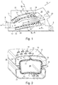
- Fig. 2 shows a perspective view of the cross section II-II of the combustion chambers 26 of Fig. 1 as an example of a combustion chamber 26 with a double-walled construction.
- the duct wall 10 is configured as a double-walled construction with an inner face 11, an outer face 12, and a wall cavity 13 extending from a cavity inlet 19 to a cavity outlet 20 along the duct wall 10.
- four wall cavities 13 are arranged in the cross section.
- Each wall cavity is extending from a cavity inlet 19 arranged on the side wall of the combustion chamber to a cavity outlet 20 arranged on a top wall, respectively bottom wall of the combustion chamber 26.
- the cooling gas 16 is feed to the cavity inlets 19 from the compressor plenum 30 surrounding the combustion chamber 26.
- An upper section and a lower section of the duct wall 10 is enclosed by a sleeve 15 forming a cooling channel 17 there between.
- the cavity outlet 20 opens to the cooling channel 17 and the cooling gas 16 discharged from the cavity outlets 20 flows towards an exit end (not shown in the cross section) of the cooling channel 17.
- the sleeve 15 For the impingement cooling of the duct wall 10 the sleeve 15 comprises apertures 14. Cooling gas 16 is injected through the apertures and 16 impinges on the duct wall 10. After impingement it flows in the cooling channel 17 towards the upstream end of the combustion chamber (not shown). In this example apertures 14 are arranged above the top and bottom sides of the duct wall 10.
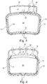
- Fig. 3 shows another example of a cross section of a combustion chamber 26 with a double-walled construction.
- the duct wall 10 is configured as a double-walled construction with an inner face 11, an outer face 12, and a wall cavity 13 extending from a cavity inlet 19 to a cavity outlet 20 along the duct wall 10.
- two wall cavities 13 are arranged in the cross section.
- Each wall cavity 13 is extending from a cavity inlet 19 arranged at the center of bottom side wall of the combustion chamber to a cavity outlet 20 arranged at the center of a top wall.
- One wall cavity 13 spans around the left half of the duct wall 10 and the other wall cavity 13 spans around the right half of the duct wall 10.
- the cooling gas 16 is feed to the cavity inlets 19 from the compressor plenum 30 surrounding the combustion chamber 26.
- An upper section of the duct wall 10 is enclosed by a sleeve 15 forming a cooling channel 17 there between.
- the top wall of the duct wall 10 is practically enclosed by the sleeve 15.
- the cavity outlet 20 opens to the cooling channel 17 and the cooling gas 16 discharged from the cavity outlets 20 flows towards an exit end (not shown in the cross section) of the cooling channel 17.
- the sleeve 15 For the impingement cooling of the duct wall 10 the sleeve 15 comprises apertures 14. Cooling gas 16 is injected through the apertures and 16 impinges on the duct wall 10. After impingement it flows in the cooling channel 17 towards the upstream end of the combustion chamber (not shown). In this example apertures 14 are arranged above the top side of the duct wall 10.
- the duct wall 10 comprises a left and a right section. Both sections are connected by an upper joint 22 and a lower joint 27.
- the cavity inlets 19 are arranged on both sides of the lower joint 27.
- the cavity outlets 20 are arranged on both sides of the upper joint 22.
- the joint can for example be a weld.
- Fig. 4 shows another example of a cross section of a combustion chamber 26 with a double-walled construction.
- the example of Fig. 4 is based on the example of Fig. 3 .
- the top section of the duct wall 10 is single-walled.
- the cavity outlets 20 are arranged towards the left, respectively the right side of the top section.
- the top section extending between the cavity outlets 20 is impingement cooled.
- Fig. 5 shows a cross section of gas turbine having a combustion arrangement with an array of double-walled combustion chambers 26 circumferentially arranged around the axis 2 of the gas turbine.
- Each combustion chamber 26 has a cylindrical duct wall 10.
- the duct walls 10 have an inner face 11 and outer face 12 and are feed with cooling gas on a side facing towards the axis 2 of the gas turbine from a compressor plenum 30 which is delimited by the rotor cover 23 and the combustor casing 31.
- the side of each combustor facing away from the axis 2 is enclosed by a sleeve 15 delimiting a cooling channel 17 between the duct wall 10 and the sleeve 15.
- cooling gas 16 discharges from the double walled duct wall 10 into the cooling channel 17 flows towards an exit end (not shown in the cross section) of the cooling channel 17.
- the outwards facing section of the duct wall 10 below the sleeve 15 is further impingement cooled by cooling gas 16 injected through apertures 14. After impingement cooling gas 16 flows in the cooling channel 17 towards the upstream end of the combustion chamber (not shown).
Landscapes
- Engineering & Computer Science (AREA)
- Chemical & Material Sciences (AREA)
- Combustion & Propulsion (AREA)
- Mechanical Engineering (AREA)
- General Engineering & Computer Science (AREA)
- Turbine Rotor Nozzle Sealing (AREA)
Claims (14)
- Brennraum (26), umfassend eine Kanalwand (10) zum Führen einer Heißgasströmung (9) in einen Heißgasströmungspfad während eines Betriebs, wobei die Kanalwand (10) eine doppelwandige Konstruktion ist, die eine innere Fläche (11), eine äußere Fläche (12) und einen Wandhohlraum (13) enthält, der sich von einem Hohlraumeinlass (19) zu einem Hohlraumauslass (20) entlang der Kanalwand (10) erstreckt, dadurch gekennzeichnet, dass eine Buchse (15) die Kanalwand (10) zum Führen eines Kühlgases (16) in einem Kühlkanal (17) zwischen der Buchse (15) und der Kanalwand (10) entlang der äußeren Oberfläche der Kanalwand (10) zu einem Ausgangsende (21) wenigstens zum Teil einschließt, und dadurch, dass der Hohlraumauslass (20) zum Kühlkanal hin öffnet.
- Brennraum (26) nach Anspruch 1, dadurch gekennzeichnet, dass die Buchse (15) mehrere Öffnungen (14) umfasst, die die Kanalwand (10) umgeben und in einer Entfernung davon derart beabstandet sind, dass Kühlgas (16), das von einem Druckgasplenum (30) durch die Öffnungen (14) während des Betriebes eingespritzt wird, auf der Kanalwand (10) aufschlägt und als Querströmung (18) zu dem Ausgangsende (21) des Kühlkanals (17) hin fließt.
- Brennraum (26) nach Anspruch 2, dadurch gekennzeichnet, dass der Hohlraumeinlass (19) mit demselben Druckgasplenum (30) verbunden ist wie die Öffnungen (14) für eine Aufschlagskühlung der Kanalwand (10).
- Brennraum (26) nach einem der Ansprüche 1 bis 3, dadurch gekennzeichnet, dass sich die Wandhohlräume (13) in eine Richtung erstrecken, die auf eine axiale Erweiterung der Verbrennungskammer (4) in Umfangsrichtung um die Kanalwand (10) herum normal ist.
- Brennraum (26) nach einem der Ansprüche 1 bis 4, dadurch gekennzeichnet, dass die Kanalwand (10) einen rechteckigen, trapezförmigen, elliptischen oder kreisförmigen Querschnitt mit dem Hohlraumeinlass (19) auf einer Seite und einem weiteren Hohlraumeinlass (19) auf einer gegenüberliegenden Seite und mit dem Hohlraumauslass (20) in einem Wandbereich, der die Hohlraumeinlässe (19) auf einer Seite der Heißgasströmung (9) verbindet, und mit einem weiteren Hohlraumauslass (20) in einem Wandbereich, der die Hohlraumeinlässe (19) auf einer gegenüberliegenden Seite der Heißgasströmung (9) verbindet, aufweist oder dadurch gekennzeichnet, dass der Hohlraumeinlass auf einer Seite liegt und der Hohlraumauslass auf einer gegenüberliegenden Seite liegt, wobei sich der Wandhohlraum (13) von dem Hohlraumeinlass auf einer Seite zu dem Hohlraumauslass auf der gegenüberliegenden Seite erstreckt.
- Brennraum (26) nach einem der Ansprüche 1 bis 5, dadurch gekennzeichnet, dass der Hohlraumeinlass (19) und/oder der Hohlraumauslass (20) neben einem Gelenk (22, 27) angeordnet ist, an dem zwei Bereiche der Kanalwand (10) verbunden sind.
- Brennraum (26) nach einem der Ansprüche 1 bis 6, dadurch gekennzeichnet, dass ein erster Bereich der Kanalwand (10) als eine Doppelwand konfiguriert ist, die den Wandhohlraum (13) umfasst, und ein zweiter Bereich als eine einzelne Wand konfiguriert ist, in die sich der zweite Bereich unterhalb der Buchse (15) erstreckt.
- Gasturbine (1) mit wenigstens einem Kompressor (3) und wenigstens einer Turbine (5), dadurch gekennzeichnet, dass sie wenigstens einen Brennraum (26) nach einem der Ansprüche 1 bis 7 umfasst.
- Gasturbine (1) nach Anspruch 8, dadurch gekennzeichnet, dass das Ausgangsende (21) des Kühlkanals (17) mit einem Brenner (25) der Gasturbine (1) zum Einführen des Kühlgases (16) in den Brenner (25) während eines Betriebs verbunden ist.
- Gasturbine (1) nach Anspruch 8, dadurch gekennzeichnet, dass mehrere Brennräume (26) in Umfangsrichtung um die Achse (2) der Gasturbine (9) herum angeordnet sind, und dadurch, dass die Kanalwand (10) zweier benachbarter Brennräume (26), die einander zugewandt sind, als eine Doppelwand mit einem Wandhohlraum (13) konfiguriert ist, und dadurch, dass die Buchse (15) über einem Bereich der Kanalwand (10) angeordnet ist, der der Achse (2) der Gasturbine (1) zugewandt ist, und/oder dadurch, dass die Buchse (15) über einem Bereich der Kanalwand (10) angeordnet ist, der von der Achse (2) der Gasturbine (1) abgewandt ist.
- Gasturbine (1) nach Anspruch 8, dadurch gekennzeichnet, dass mehrere Brennräume (26) in Umfangsrichtung um die Achse (2) der Gasturbine (9) herum angeordnet sind, dadurch, dass der Hohlraumeinlass (19) auf einem Bereich der Kanalwand (10) zweier benachbarter Brennräume (26), die einander zugewandt sind, angeordnet ist, und dadurch, dass die Buchse (15) über einem Bereich der Kanalwand (10) angeordnet ist, der der Achse (2) der Gasturbine (1) zugewandt ist, und/oder dadurch, dass die Buchse (15) über einem Bereich der Kanalwand (10) angeordnet ist, der von der Achse (2) der Gasturbine (1) abgewandt ist.
- Verfahren zum Kühlen eines Brennraums (26), umfassend eine Kanalwand (10) zum Führen einer Heißgasströmung (9) in einen Heißgasströmungspfad während eines Betriebs, wobei die Kanalwand (10) eine doppelwandige Konstruktion ist, die eine innere Fläche (11), eine äußere Fläche (12) und einen Wandhohlraum (13) enthält, der sich von einem Hohlraumeinlass (19) zu einem Hohlraumauslass (20) entlang der Kanalwand (10) erstreckt, dadurch gekennzeichnet, dass eine Buchse (15) die Kanalwand (10) zum Führen eines Kühlgases (16) in einem Kühlkanal (17) zwischen der Buchse (15) und der Kanalwand (10) entlang der äußeren Oberfläche der Kanalwand (10) wenigstens zum Teil einschließt und ein Kühlfluid in den Hohlraumeinlass (19) eingespeist wird, durch den Wandhohlraum (13) zum Kühlen der Kanalwand (10) fließt und in den Kühlkanal (17) durch einen Hohlraumauslass (20) für weiteres konvexes Kühlen der Kanalwand (10) herausfließt.
- Verfahren zum Kühlen eines Brennraums (26) nach Anspruch 12, dadurch gekennzeichnet, dass ein Kühlgas (16) durch mehrere Öffnungen (14) in der umgebenden Buchse (15) eingespritzt wird, die in einer Entfernung von der Kanalwand (10) derartig beabstandet ist, dass das Kühlgas (16) von einem Druckgasplenum (30), das durch die Öffnungen (14) verläuft, auf der Kanalwand (10) aufschlägt und als eine Querströmung (18) zu einem Ausgangsende (21) des Kühlkanals (17) hin fließt.
- Verfahren zum Kühlen eines Brennraums (26) nach Anspruch 13, dadurch gekennzeichnet, dass das Kühlgas (16) von einem Druckgasplenum (30) zu dem Wandhohlraum (13) durch den Hohlraumeinlass (19) gespeist wird und in den Kühlkanal (17) von dem Hohlraumauslass (20) herausfließt, und dadurch, dass Kühlgas (16) von demselben Kühlplenum (30) durch die Öffnungen (14) eingespritzt wird, auf der Kanalwand (10) aufschlägt und als Querströmung (18) durch denselben Kühlkanal (17) fließt wie das Kühlgas (16), das aus dem Hohlraumauslass (20) herausfließt.
Priority Applications (5)
| Application Number | Priority Date | Filing Date | Title |
|---|---|---|---|
| EP15158820.9A EP3067622B1 (de) | 2015-03-12 | 2015-03-12 | Brennkammer mit doppelwand und verahren zur kühlung der brennkammer |
| CN201610138281.6A CN105972637B (zh) | 2015-03-12 | 2016-03-11 | 具有双壁的燃烧室 |
| JP2016048970A JP2016186415A (ja) | 2015-03-12 | 2016-03-11 | 二重壁を備える燃焼室 |
| US15/068,100 US10648667B2 (en) | 2015-03-12 | 2016-03-11 | Combustion chamber with double wall |
| KR1020160030134A KR20160110264A (ko) | 2015-03-12 | 2016-03-14 | 이중벽을 갖는 연소 챔버 |
Applications Claiming Priority (1)
| Application Number | Priority Date | Filing Date | Title |
|---|---|---|---|
| EP15158820.9A EP3067622B1 (de) | 2015-03-12 | 2015-03-12 | Brennkammer mit doppelwand und verahren zur kühlung der brennkammer |
Publications (2)
| Publication Number | Publication Date |
|---|---|
| EP3067622A1 EP3067622A1 (de) | 2016-09-14 |
| EP3067622B1 true EP3067622B1 (de) | 2018-12-26 |
Family
ID=52633180
Family Applications (1)
| Application Number | Title | Priority Date | Filing Date |
|---|---|---|---|
| EP15158820.9A Active EP3067622B1 (de) | 2015-03-12 | 2015-03-12 | Brennkammer mit doppelwand und verahren zur kühlung der brennkammer |
Country Status (5)
| Country | Link |
|---|---|
| US (1) | US10648667B2 (de) |
| EP (1) | EP3067622B1 (de) |
| JP (1) | JP2016186415A (de) |
| KR (1) | KR20160110264A (de) |
| CN (1) | CN105972637B (de) |
Families Citing this family (4)
| Publication number | Priority date | Publication date | Assignee | Title |
|---|---|---|---|---|
| US10316746B2 (en) * | 2015-02-04 | 2019-06-11 | General Electric Company | Turbine system with exhaust gas recirculation, separation and extraction |
| EP3342991B1 (de) * | 2016-12-30 | 2020-10-14 | Ansaldo Energia IP UK Limited | Prallplatten für kühlung in einer gasturbine |
| CN106949497B (zh) * | 2017-03-10 | 2019-10-15 | 中国人民解放军战略支援部队航天工程大学 | 一种用喷雾碰壁强化换热的再生冷却双流道方案 |
| CN113739208B (zh) * | 2021-09-09 | 2022-08-26 | 成都中科翼能科技有限公司 | 一种用于低污染燃气轮机的混合冷却火焰筒 |
Family Cites Families (13)
| Publication number | Priority date | Publication date | Assignee | Title |
|---|---|---|---|---|
| CA1309873C (en) * | 1987-04-01 | 1992-11-10 | Graham P. Butt | Gas turbine combustor transition duct forced convection cooling |
| CH674561A5 (de) | 1987-12-21 | 1990-06-15 | Bbc Brown Boveri & Cie | |
| CN2097963U (zh) * | 1991-04-18 | 1992-03-04 | 韩照彦 | 旋转燃烧室 |
| JP3415663B2 (ja) * | 1992-12-28 | 2003-06-09 | アルストム | 冷却面を衝撃式に冷却するための装置 |
| DE19547913A1 (de) | 1995-12-21 | 1997-06-26 | Abb Research Ltd | Brenner für einen Wärmeerzeuger |
| US6935116B2 (en) | 2003-04-28 | 2005-08-30 | Power Systems Mfg., Llc | Flamesheet combustor |
| US7827801B2 (en) * | 2006-02-09 | 2010-11-09 | Siemens Energy, Inc. | Gas turbine engine transitions comprising closed cooled transition cooling channels |
| CN100510541C (zh) * | 2007-06-27 | 2009-07-08 | 北京航空航天大学 | 单涡燃烧室 |
| EP2031302A1 (de) | 2007-08-27 | 2009-03-04 | Siemens Aktiengesellschaft | Gasturbine mit einer kühlbaren Komponente |
| US8096133B2 (en) * | 2008-05-13 | 2012-01-17 | General Electric Company | Method and apparatus for cooling and dilution tuning a gas turbine combustor liner and transition piece interface |
| US20100071377A1 (en) * | 2008-09-19 | 2010-03-25 | Fox Timothy A | Combustor Apparatus for Use in a Gas Turbine Engine |
| CN101694301B (zh) * | 2009-09-25 | 2010-12-08 | 北京航空航天大学 | 对冲火焰燃烧室 |
| EP2722591A1 (de) | 2012-10-22 | 2014-04-23 | Alstom Technology Ltd | Mehrfach-Kegelbrenner für eine Gasturbine |
-
2015
- 2015-03-12 EP EP15158820.9A patent/EP3067622B1/de active Active
-
2016
- 2016-03-11 US US15/068,100 patent/US10648667B2/en active Active
- 2016-03-11 CN CN201610138281.6A patent/CN105972637B/zh active Active
- 2016-03-11 JP JP2016048970A patent/JP2016186415A/ja active Pending
- 2016-03-14 KR KR1020160030134A patent/KR20160110264A/ko not_active Withdrawn
Non-Patent Citations (1)
| Title |
|---|
| None * |
Also Published As
| Publication number | Publication date |
|---|---|
| JP2016186415A (ja) | 2016-10-27 |
| EP3067622A1 (de) | 2016-09-14 |
| US10648667B2 (en) | 2020-05-12 |
| US20160265776A1 (en) | 2016-09-15 |
| KR20160110264A (ko) | 2016-09-21 |
| CN105972637A (zh) | 2016-09-28 |
| CN105972637B (zh) | 2021-01-29 |
Similar Documents
| Publication | Publication Date | Title |
|---|---|---|
| US8544277B2 (en) | Turbulated aft-end liner assembly and cooling method | |
| EP2500523B1 (de) | Hinterrahmen und verfahren zum kühlen des hinterrahmens | |
| EP2378200B1 (de) | Brennkammerwandkühlung an der überleitkanalschnittstelle und zugehöriges verfahren | |
| US8590314B2 (en) | Combustor liner helical cooling apparatus | |
| CN100393997C (zh) | 燃烧室 | |
| CN104566381B (zh) | 燃烧器冷却结构 | |
| US8959886B2 (en) | Mesh cooled conduit for conveying combustion gases | |
| JP6367559B2 (ja) | ターボ機械の冷却が改善された移行ダクト | |
| US20090120093A1 (en) | Turbulated aft-end liner assembly and cooling method | |
| EP2921779B1 (de) | Brennkammer mit Kühlhülse | |
| EP2211105A2 (de) | Hinterkantenverkleidungsanordnung einer Brennkammerwand mit Turbulatoren und dazugehöriges Kühlungsverfahren | |
| EP2375160A2 (de) | Kühlsystem mit abgewinkelter Dichtung | |
| US10648667B2 (en) | Combustion chamber with double wall | |
| US20110110761A1 (en) | Gas turbine having an improved cooling architecture | |
| JP5537895B2 (ja) | ガスタービン燃焼器 | |
| EP2532836A2 (de) | Brennermantel und Übergangsstück | |
| US11215072B2 (en) | Aft frame assembly for gas turbine transition piece | |
| US20150159873A1 (en) | Compressor discharge casing assembly | |
| CN105531543A (zh) | 具有火焰管端部区域的管式燃烧室和燃气轮机 | |
| CN100370177C (zh) | 用于燃烧一种可燃烧的液态混合燃料的燃烧室 | |
| KR101842745B1 (ko) | 가스터빈의 트랜지션피스와 터빈의 결합장치 |
Legal Events
| Date | Code | Title | Description |
|---|---|---|---|
| PUAI | Public reference made under article 153(3) epc to a published international application that has entered the european phase |
Free format text: ORIGINAL CODE: 0009012 |
|
| AK | Designated contracting states |
Kind code of ref document: A1 Designated state(s): AL AT BE BG CH CY CZ DE DK EE ES FI FR GB GR HR HU IE IS IT LI LT LU LV MC MK MT NL NO PL PT RO RS SE SI SK SM TR |
|
| AX | Request for extension of the european patent |
Extension state: BA ME |
|
| STAA | Information on the status of an ep patent application or granted ep patent |
Free format text: STATUS: REQUEST FOR EXAMINATION WAS MADE |
|
| 17P | Request for examination filed |
Effective date: 20170313 |
|
| RBV | Designated contracting states (corrected) |
Designated state(s): AL AT BE BG CH CY CZ DE DK EE ES FI FR GB GR HR HU IE IS IT LI LT LU LV MC MK MT NL NO PL PT RO RS SE SI SK SM TR |
|
| RAP1 | Party data changed (applicant data changed or rights of an application transferred) |
Owner name: ANSALDO ENERGIA SWITZERLAND AG |
|
| GRAP | Despatch of communication of intention to grant a patent |
Free format text: ORIGINAL CODE: EPIDOSNIGR1 |
|
| STAA | Information on the status of an ep patent application or granted ep patent |
Free format text: STATUS: GRANT OF PATENT IS INTENDED |
|
| INTG | Intention to grant announced |
Effective date: 20180709 |
|
| GRAS | Grant fee paid |
Free format text: ORIGINAL CODE: EPIDOSNIGR3 |
|
| GRAA | (expected) grant |
Free format text: ORIGINAL CODE: 0009210 |
|
| STAA | Information on the status of an ep patent application or granted ep patent |
Free format text: STATUS: THE PATENT HAS BEEN GRANTED |
|
| AK | Designated contracting states |
Kind code of ref document: B1 Designated state(s): AL AT BE BG CH CY CZ DE DK EE ES FI FR GB GR HR HU IE IS IT LI LT LU LV MC MK MT NL NO PL PT RO RS SE SI SK SM TR |
|
| REG | Reference to a national code |
Ref country code: GB Ref legal event code: FG4D |
|
| REG | Reference to a national code |
Ref country code: CH Ref legal event code: EP |
|
| REG | Reference to a national code |
Ref country code: AT Ref legal event code: REF Ref document number: 1081921 Country of ref document: AT Kind code of ref document: T Effective date: 20190115 |
|
| REG | Reference to a national code |
Ref country code: DE Ref legal event code: R096 Ref document number: 602015022110 Country of ref document: DE |
|
| REG | Reference to a national code |
Ref country code: IE Ref legal event code: FG4D |
|
| PG25 | Lapsed in a contracting state [announced via postgrant information from national office to epo] |
Ref country code: FI Free format text: LAPSE BECAUSE OF FAILURE TO SUBMIT A TRANSLATION OF THE DESCRIPTION OR TO PAY THE FEE WITHIN THE PRESCRIBED TIME-LIMIT Effective date: 20181226 Ref country code: LV Free format text: LAPSE BECAUSE OF FAILURE TO SUBMIT A TRANSLATION OF THE DESCRIPTION OR TO PAY THE FEE WITHIN THE PRESCRIBED TIME-LIMIT Effective date: 20181226 Ref country code: HR Free format text: LAPSE BECAUSE OF FAILURE TO SUBMIT A TRANSLATION OF THE DESCRIPTION OR TO PAY THE FEE WITHIN THE PRESCRIBED TIME-LIMIT Effective date: 20181226 Ref country code: BG Free format text: LAPSE BECAUSE OF FAILURE TO SUBMIT A TRANSLATION OF THE DESCRIPTION OR TO PAY THE FEE WITHIN THE PRESCRIBED TIME-LIMIT Effective date: 20190326 Ref country code: LT Free format text: LAPSE BECAUSE OF FAILURE TO SUBMIT A TRANSLATION OF THE DESCRIPTION OR TO PAY THE FEE WITHIN THE PRESCRIBED TIME-LIMIT Effective date: 20181226 Ref country code: NO Free format text: LAPSE BECAUSE OF FAILURE TO SUBMIT A TRANSLATION OF THE DESCRIPTION OR TO PAY THE FEE WITHIN THE PRESCRIBED TIME-LIMIT Effective date: 20190326 |
|
| REG | Reference to a national code |
Ref country code: NL Ref legal event code: MP Effective date: 20181226 |
|
| REG | Reference to a national code |
Ref country code: LT Ref legal event code: MG4D |
|
| PG25 | Lapsed in a contracting state [announced via postgrant information from national office to epo] |
Ref country code: AL Free format text: LAPSE BECAUSE OF FAILURE TO SUBMIT A TRANSLATION OF THE DESCRIPTION OR TO PAY THE FEE WITHIN THE PRESCRIBED TIME-LIMIT Effective date: 20181226 Ref country code: GR Free format text: LAPSE BECAUSE OF FAILURE TO SUBMIT A TRANSLATION OF THE DESCRIPTION OR TO PAY THE FEE WITHIN THE PRESCRIBED TIME-LIMIT Effective date: 20190327 Ref country code: RS Free format text: LAPSE BECAUSE OF FAILURE TO SUBMIT A TRANSLATION OF THE DESCRIPTION OR TO PAY THE FEE WITHIN THE PRESCRIBED TIME-LIMIT Effective date: 20181226 Ref country code: SE Free format text: LAPSE BECAUSE OF FAILURE TO SUBMIT A TRANSLATION OF THE DESCRIPTION OR TO PAY THE FEE WITHIN THE PRESCRIBED TIME-LIMIT Effective date: 20181226 |
|
| REG | Reference to a national code |
Ref country code: AT Ref legal event code: MK05 Ref document number: 1081921 Country of ref document: AT Kind code of ref document: T Effective date: 20181226 |
|
| PG25 | Lapsed in a contracting state [announced via postgrant information from national office to epo] |
Ref country code: NL Free format text: LAPSE BECAUSE OF FAILURE TO SUBMIT A TRANSLATION OF THE DESCRIPTION OR TO PAY THE FEE WITHIN THE PRESCRIBED TIME-LIMIT Effective date: 20181226 |
|
| PG25 | Lapsed in a contracting state [announced via postgrant information from national office to epo] |
Ref country code: CZ Free format text: LAPSE BECAUSE OF FAILURE TO SUBMIT A TRANSLATION OF THE DESCRIPTION OR TO PAY THE FEE WITHIN THE PRESCRIBED TIME-LIMIT Effective date: 20181226 Ref country code: IT Free format text: LAPSE BECAUSE OF FAILURE TO SUBMIT A TRANSLATION OF THE DESCRIPTION OR TO PAY THE FEE WITHIN THE PRESCRIBED TIME-LIMIT Effective date: 20181226 Ref country code: ES Free format text: LAPSE BECAUSE OF FAILURE TO SUBMIT A TRANSLATION OF THE DESCRIPTION OR TO PAY THE FEE WITHIN THE PRESCRIBED TIME-LIMIT Effective date: 20181226 Ref country code: PT Free format text: LAPSE BECAUSE OF FAILURE TO SUBMIT A TRANSLATION OF THE DESCRIPTION OR TO PAY THE FEE WITHIN THE PRESCRIBED TIME-LIMIT Effective date: 20190426 Ref country code: PL Free format text: LAPSE BECAUSE OF FAILURE TO SUBMIT A TRANSLATION OF THE DESCRIPTION OR TO PAY THE FEE WITHIN THE PRESCRIBED TIME-LIMIT Effective date: 20181226 |
|
| PG25 | Lapsed in a contracting state [announced via postgrant information from national office to epo] |
Ref country code: EE Free format text: LAPSE BECAUSE OF FAILURE TO SUBMIT A TRANSLATION OF THE DESCRIPTION OR TO PAY THE FEE WITHIN THE PRESCRIBED TIME-LIMIT Effective date: 20181226 Ref country code: SM Free format text: LAPSE BECAUSE OF FAILURE TO SUBMIT A TRANSLATION OF THE DESCRIPTION OR TO PAY THE FEE WITHIN THE PRESCRIBED TIME-LIMIT Effective date: 20181226 Ref country code: SK Free format text: LAPSE BECAUSE OF FAILURE TO SUBMIT A TRANSLATION OF THE DESCRIPTION OR TO PAY THE FEE WITHIN THE PRESCRIBED TIME-LIMIT Effective date: 20181226 Ref country code: IS Free format text: LAPSE BECAUSE OF FAILURE TO SUBMIT A TRANSLATION OF THE DESCRIPTION OR TO PAY THE FEE WITHIN THE PRESCRIBED TIME-LIMIT Effective date: 20190426 Ref country code: RO Free format text: LAPSE BECAUSE OF FAILURE TO SUBMIT A TRANSLATION OF THE DESCRIPTION OR TO PAY THE FEE WITHIN THE PRESCRIBED TIME-LIMIT Effective date: 20181226 |
|
| REG | Reference to a national code |
Ref country code: DE Ref legal event code: R097 Ref document number: 602015022110 Country of ref document: DE |
|
| PG25 | Lapsed in a contracting state [announced via postgrant information from national office to epo] |
Ref country code: MC Free format text: LAPSE BECAUSE OF FAILURE TO SUBMIT A TRANSLATION OF THE DESCRIPTION OR TO PAY THE FEE WITHIN THE PRESCRIBED TIME-LIMIT Effective date: 20181226 Ref country code: DK Free format text: LAPSE BECAUSE OF FAILURE TO SUBMIT A TRANSLATION OF THE DESCRIPTION OR TO PAY THE FEE WITHIN THE PRESCRIBED TIME-LIMIT Effective date: 20181226 Ref country code: AT Free format text: LAPSE BECAUSE OF FAILURE TO SUBMIT A TRANSLATION OF THE DESCRIPTION OR TO PAY THE FEE WITHIN THE PRESCRIBED TIME-LIMIT Effective date: 20181226 |
|
| REG | Reference to a national code |
Ref country code: CH Ref legal event code: PL |
|
| PLBE | No opposition filed within time limit |
Free format text: ORIGINAL CODE: 0009261 |
|
| STAA | Information on the status of an ep patent application or granted ep patent |
Free format text: STATUS: NO OPPOSITION FILED WITHIN TIME LIMIT |
|
| GBPC | Gb: european patent ceased through non-payment of renewal fee |
Effective date: 20190326 |
|
| PG25 | Lapsed in a contracting state [announced via postgrant information from national office to epo] |
Ref country code: LU Free format text: LAPSE BECAUSE OF NON-PAYMENT OF DUE FEES Effective date: 20190312 |
|
| 26N | No opposition filed |
Effective date: 20190927 |
|
| REG | Reference to a national code |
Ref country code: BE Ref legal event code: MM Effective date: 20190331 |
|
| PG25 | Lapsed in a contracting state [announced via postgrant information from national office to epo] |
Ref country code: LI Free format text: LAPSE BECAUSE OF NON-PAYMENT OF DUE FEES Effective date: 20190331 Ref country code: IE Free format text: LAPSE BECAUSE OF NON-PAYMENT OF DUE FEES Effective date: 20190312 Ref country code: CH Free format text: LAPSE BECAUSE OF NON-PAYMENT OF DUE FEES Effective date: 20190331 Ref country code: GB Free format text: LAPSE BECAUSE OF NON-PAYMENT OF DUE FEES Effective date: 20190326 |
|
| PG25 | Lapsed in a contracting state [announced via postgrant information from national office to epo] |
Ref country code: SI Free format text: LAPSE BECAUSE OF FAILURE TO SUBMIT A TRANSLATION OF THE DESCRIPTION OR TO PAY THE FEE WITHIN THE PRESCRIBED TIME-LIMIT Effective date: 20181226 Ref country code: FR Free format text: LAPSE BECAUSE OF NON-PAYMENT OF DUE FEES Effective date: 20190331 Ref country code: BE Free format text: LAPSE BECAUSE OF NON-PAYMENT OF DUE FEES Effective date: 20190331 |
|
| PG25 | Lapsed in a contracting state [announced via postgrant information from national office to epo] |
Ref country code: TR Free format text: LAPSE BECAUSE OF FAILURE TO SUBMIT A TRANSLATION OF THE DESCRIPTION OR TO PAY THE FEE WITHIN THE PRESCRIBED TIME-LIMIT Effective date: 20181226 |
|
| PG25 | Lapsed in a contracting state [announced via postgrant information from national office to epo] |
Ref country code: MT Free format text: LAPSE BECAUSE OF NON-PAYMENT OF DUE FEES Effective date: 20190312 |
|
| PG25 | Lapsed in a contracting state [announced via postgrant information from national office to epo] |
Ref country code: CY Free format text: LAPSE BECAUSE OF FAILURE TO SUBMIT A TRANSLATION OF THE DESCRIPTION OR TO PAY THE FEE WITHIN THE PRESCRIBED TIME-LIMIT Effective date: 20181226 |
|
| PG25 | Lapsed in a contracting state [announced via postgrant information from national office to epo] |
Ref country code: HU Free format text: LAPSE BECAUSE OF FAILURE TO SUBMIT A TRANSLATION OF THE DESCRIPTION OR TO PAY THE FEE WITHIN THE PRESCRIBED TIME-LIMIT; INVALID AB INITIO Effective date: 20150312 |
|
| PG25 | Lapsed in a contracting state [announced via postgrant information from national office to epo] |
Ref country code: MK Free format text: LAPSE BECAUSE OF FAILURE TO SUBMIT A TRANSLATION OF THE DESCRIPTION OR TO PAY THE FEE WITHIN THE PRESCRIBED TIME-LIMIT Effective date: 20181226 |
|
| P01 | Opt-out of the competence of the unified patent court (upc) registered |
Effective date: 20240430 |
|
| PGFP | Annual fee paid to national office [announced via postgrant information from national office to epo] |
Ref country code: DE Payment date: 20250319 Year of fee payment: 11 |