EP3067312B1 - Device for emptying an urea solution container - Google Patents
Device for emptying an urea solution container Download PDFInfo
- Publication number
- EP3067312B1 EP3067312B1 EP16160090.3A EP16160090A EP3067312B1 EP 3067312 B1 EP3067312 B1 EP 3067312B1 EP 16160090 A EP16160090 A EP 16160090A EP 3067312 B1 EP3067312 B1 EP 3067312B1
- Authority
- EP
- European Patent Office
- Prior art keywords
- tube
- urea solution
- inner tube
- outer tube
- emptying
- Prior art date
- Legal status (The legal status is an assumption and is not a legal conclusion. Google has not performed a legal analysis and makes no representation as to the accuracy of the status listed.)
- Active
Links
Images


Classifications
-
- B—PERFORMING OPERATIONS; TRANSPORTING
- B67—OPENING, CLOSING OR CLEANING BOTTLES, JARS OR SIMILAR CONTAINERS; LIQUID HANDLING
- B67D—DISPENSING, DELIVERING OR TRANSFERRING LIQUIDS, NOT OTHERWISE PROVIDED FOR
- B67D7/00—Apparatus or devices for transferring liquids from bulk storage containers or reservoirs into vehicles or into portable containers, e.g. for retail sale purposes
- B67D7/005—Spouts
-
- B—PERFORMING OPERATIONS; TRANSPORTING
- B67—OPENING, CLOSING OR CLEANING BOTTLES, JARS OR SIMILAR CONTAINERS; LIQUID HANDLING
- B67D—DISPENSING, DELIVERING OR TRANSFERRING LIQUIDS, NOT OTHERWISE PROVIDED FOR
- B67D7/00—Apparatus or devices for transferring liquids from bulk storage containers or reservoirs into vehicles or into portable containers, e.g. for retail sale purposes
- B67D7/02—Apparatus or devices for transferring liquids from bulk storage containers or reservoirs into vehicles or into portable containers, e.g. for retail sale purposes for transferring liquids other than fuel or lubricants
Definitions
- the invention relates to a device for emptying a urea solution container into a tank having a filler neck.
- a water-clear, synthetically produced 32.5% solution of high purity urea in demineralized water is used.
- This application takes place in an SCR catalytic converter (Selective Catalytic Reduction), where a selective catalytic reduction reduces the emission of nitrogen oxides (NO x ) by about 90%.
- SCR process uses ammonia, which is obtained on board the vehicle from urea.
- the urea solution located in a separate tank is metered into the exhaust gas flow by means of a metering pump or an injector and ensures a chemical reaction in the SCR catalytic converter in which the nitrogen oxides are converted into nitrogen and hydrogen.
- the ratio of urea solution to diesel fuel is about 1:20 to 1:30.
- a urea solution container For filling a tank with urea solution, various devices for emptying a urea solution container are known in which z. B. the entire filling is screwed with a filling nozzle to a thread of the filler neck of the tank for the urea solution.
- a container is for example from the DE 20 2008 010 648 U1 known.
- a disadvantage of such devices is that any urea solution container, which is designed to refuel a tank for urea solution of a motor vehicle, must be equipped with such a device.
- a device similar to the preamble of claim 1 is in the US 6,478,058B1 shown. However, this device is equipped with a separate vent pipe, so that it is complicated in terms of their structural design and a variety of parts must be assembled.
- the vent tube of this device is arranged centrally in the drain tube.
- the sealing plug has a sealing surface, which are connected by means of connecting webs between which passages are formed with the discharge pipe.
- This special embodiment of the invention serves to ensure that the sealing surface of Sealing plug in the closed position, the device of the invention seals liquid-tight, wherein between the sealing surface and the outer tube while an additional seal may be attached, which, however, may be formed integrally with the sealing plug.
- the connecting webs of the sealing plug are arranged on the inner tube, that the emptying tube is supported on the connecting webs. This ensures that the emptying tube within the inner tube does not shift so that it closes the passages between the connecting webs.
- the device according to the invention By means of the device according to the invention it is now possible, with a corresponding design of the union nut, to connect the device according to the invention to a corresponding urea solution container, which serves to be attached to a filler neck of a tank in order to empty the container into the tank. It is ensured by the device according to the invention that it can be connected in a liquid-tight manner to a corresponding urea solution container in order to empty it into the tank. Thus, it is no longer necessary to design the urea solution containers themselves with a corresponding connection element, since the device can be used again and again for corresponding urea solution containers by their detachable connection by means of the union nut.
- the Federkraftbeetzschlagung is generated by a coil spring, which is arranged between the inner tube and outer tube such that it is supported on the one hand on a second abutment surface of the inner tube and on the other hand on a first abutment surface of the outer tube. This ensures that the outer tube can be moved against the spring force of the coil spring on the inner tube.
- the device according to the invention is closed liquid-tight in a closed position, while in an open position, in which the outer tube has been displaced on the inner tube against the spring force of the coil spring, the device mounted on a urea solution container such releases that It can be transferred through the urea solution from the urea solution container in the designated tank.
- the connecting webs can be provided at its the sealing surface opposite end with clips or locking elements, through which the sealing plug can be connected via corresponding Jacobclips- or counter-locking elements releasably connected to the inner tube.
- the sealing plug remains connected to the inner tube via the connecting webs.
- the urea solution it is now possible for the urea solution to be transferred through the arranged between the connecting webs passages from the urea solution container in the tank.
- a second contact surface is formed on the outer tube, which liquid-tight can be placed on a filler neck of the tank.
- the union nut which rests against the first bearing surface of the inner tube, an internal thread, with which the device is connectable to an external thread of a discharge opening of a urea solution container.
- a third abutment surface of the outer tube is formed on the outer tube, on which a second union nut is supported, with which the device is connectable to the filler neck of a tank.
- the second union nut has an internal thread, through which the device with an external thread of the filler neck of a tank is connectable.
- one or more of the passages arranged between the connecting webs are partially or completely closed with corresponding walls.
- different flow rates can be achieved by using different sealing plugs for the same urea solution containers.
- a safe venting of the urea solution container can be done so that this is emptied completely, because even then the vent tube is not closed.
- a vent hose can be connected to the vent pipe, which projects into the urea solution container, preferably up to the bottom thereof. This ensures once again that a venting and thus a complete emptying of the urea solution container is made possible.
- the inner tube on a third contact surface of the inner tube which serves as a stop for the outer tube when moving the outer tube on the inner tube in the open position of the device. This ensures that the device can be effectively transferred from its closed position to its open position after connecting the urea fluid container connected to the device to the filler neck. As soon as the outer tube has reached the third contact surface of the inner tube when the outer tube is displaced on the inner tube, further displacement is no longer possible and the open position is effectively achieved. This ensures that the corresponding urea solution containers are emptied safely and effectively completely.
- FIGS. 1 to 3 and FIG. 10 show an exemplary embodiment of a device according to the invention for discharging a urea solution container into a tank having a filler neck in various views.
- FIGS. 4 to 10 show the sequential structure of the embodiment in successive steps.
- FIG. 6 now shows an inner tube 3 of the device according to the invention, in which the emptying tube 2 according to the FIGS. 4 to 5b is arranged.
- the stop surface 6 serves to bear a first union nut 5, with which the device according to the invention can be connected to a urea solution container.
- the applied to this contact surface 6 union nut 5 is in FIG. 7 already shown.
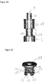
- FIG. 9 a second union nut 17 is introduced to the inner tube 3, which then according to the representation of FIG. 10 the outer tube 4 applied is and a sealing plug 7 is connected to the inner tube 3.
- this embodiment of the device according to the invention for emptying a urea solution container is shown in its closed position. This means that no urea can emerge from this device when it is connected by means of its union nut 5 and an internal thread 16 contained therein with an external thread of a filler neck of a tank to be filled.
- FIG. 10 This position of FIG. 10 or the FIG. 1 is in the FIG. 2 shown in a sectional view in which the essential elements and the operation of the device according to the invention can be seen better.
- the presentation of the FIG. 2 is along the cutting plane AA according to the FIG. 1 shown.
- the emptying tube 2 with its venting tube 1 is arranged inside the inner tube 3.
- the emptying tube 2 is supported on webs 12 of the sealing plug 7 from. This avoids that the emptying tube 2 is displaced too far within the inner tube and thus closes the arranged between the connecting webs 12 passages 13 for the urea solution.
- the outer tube 4 in this case has a further stop surface 14, with which the entire device and the outer tube 4 can be applied liquid-tight to a filler neck of a tank to be filled.
- a further union nut 17 is provided which has an internal thread 18 which corresponds to a corresponding external thread of the filler neck of the tank to be filled.
- the urea solution container including the device according to the invention in the direction of the filler neck of the tank moves, with the outer tube 4 on the inner tube three against the spring force of the coil spring 8 shifts so that the device of Your closing is transferred to the open position.
- vent pipe 1 By means of the vent pipe 1, on which advantageously still a vent hose extending to the bottom of the urea solution container is arranged, this can be vented during the emptying of the urea solution container, so that a complete emptying of the urea solution container is ensured.
- the outer tube 4 is moved on the inner tube 3 again by the spring force of the coil spring 8 until the device again their closed position according to the FIG. 2 has taken.
- the device according to the invention can now be solved with the urea solution container again from the filler neck of the filled tank and subsequently the device according to the invention can also be emptied from the emptied urea solution container.
Description
Die Erfindung betrifft Vorrichtung zum Entleeren eines Harnstofflösungsbehältnisses in einen einen Einfüllstutzen aufweisenden Tank.The invention relates to a device for emptying a urea solution container into a tank having a filler neck.
Bei der Abgasnachbehandlung von Automobil- Dieselmotoren wird eine wasserklare, synthetisch hergestellte 32,5 %-ige Lösung von hochreinem Harnstoff in demineralisiertem Wasser verwendet. Diese Anwendung findet dabei in einem SCR-Katalysator (Selective Catalytic Reduction) statt, wo durch eine selektive katalytische Reduktion der Ausstoß von Stickoxiden (NOx) um etwa 90 % reduziert wird. Das SCR-Verfahren nutzt dabei Ammoniak, welches an Bord des Fahrzeugs aus Harnstoff gewonnen wird. Die in einem separaten Tank liegende Harnstofflösung wird dabei mittels einer Dosierpumpe oder eines Injektors dosiert in den Abgasstrom eingespritzt und sorgt im SCR-Katalysator für eine chemische Reaktion, bei der die Stickoxide in Stickstoff und Wasserstoff umgewandelt werden. Das Verhältnis von Harnstofflösung zu Dieselkraftstoff beträgt dabei etwa 1:20 bis 1:30.In exhaust aftertreatment of automotive diesel engines, a water-clear, synthetically produced 32.5% solution of high purity urea in demineralized water is used. This application takes place in an SCR catalytic converter (Selective Catalytic Reduction), where a selective catalytic reduction reduces the emission of nitrogen oxides (NO x ) by about 90%. The SCR process uses ammonia, which is obtained on board the vehicle from urea. The urea solution located in a separate tank is metered into the exhaust gas flow by means of a metering pump or an injector and ensures a chemical reaction in the SCR catalytic converter in which the nitrogen oxides are converted into nitrogen and hydrogen. The ratio of urea solution to diesel fuel is about 1:20 to 1:30.
Damit dieses Abgasnachbehandlungsverfahren eingesetzt werden kann, ist es notwendig, Kraftfahrzeuge mit zusätzlichen Tanks, in welchen Harnstofflösung eingebracht wird zu bestücken. Diese Tanks müssen nachdem der darin enthaltene Harnstofflösungsvorrat zur Neige geht wieder befüllt werden. Hierzu weist der Harnstofflösungstank einen separaten Einfüllstutzen auf, der in der Regel in der Nähe des Dieselkraftstoffeinfüllstutzens angeordnet ist. Die unterschiedlichen Einfüllstutzen für Dieselkraftstoff und Harnstofflösung sind dabei mit einem Deckel mit unterschiedlichem Gewinde verschlossen.For this exhaust aftertreatment process to be used, it is necessary to equip vehicles with additional tanks in which urea solution is introduced. These tanks must be refilled after the urea solution supply contained in them is low. For this purpose, the urea solution tank on a separate filler neck, which is usually arranged in the vicinity of the diesel fuel filler neck. The different filler necks for diesel fuel and urea solution are closed with a lid with different threads.
Zum Befüllen eines Tanks mit Harnstofflösung sind verschiedene Vorrichtungen zum Entleeren eines Harnstofflösungsbehältnisses bekannt, bei denen z. B. die gesamte Befüllvorrichtung mit einem Befüllstutzen auf ein Gewinde des Einfüllstutzens des Tanks für die Harnstofflösung aufgeschraubt wird. Ein derartiger Behälter ist beispielsweise aus der
Nachteilig bei derartigen Vorrichtungen ist allerdings, dass jedes Harnstofflösungsbehältnis, welches zum Betanken eines Tanks für Harnstofflösung eines Kraftfahrzeugs ausgebildet ist, mit einer derartigen Vorrichtung ausgestattet sein muss.A disadvantage of such devices, however, is that any urea solution container, which is designed to refuel a tank for urea solution of a motor vehicle, must be equipped with such a device.
Eine Vorrichtung ähnlich dem Oberbegriff des Patentanspruchs 1 wird in der
Es ist daher Aufgabe der Erfindung, eine Vorrichtung zum Entleeren eines Harnstofflösungsbehältnisses in einem einen Einfüllstutzen aufweisenden Tank eines Kraftfahrzeuges bereitzustellen, welche konstruktiv einfach aufgebaut sowie an unterschiedliche Harnstofflösungsbehältnisse angebracht und für weitere Harnstofflösungsbehältnisse wiederverwendet werden kann.It is therefore an object of the invention to provide a device for emptying a urea solution container in a filler neck having a tank of a motor vehicle, which can be structurally simple and attached to different urea solution containers and reused for other urea solution containers.
Gelöst wird diese Aufgabe durch eine Vorrichtung mit allen Merkmalen des Patentanspruchs 1. Vorteilhafte Ausgestaltungen der Erfindung finden sich in den Unteransprüchen.This object is achieved by a device with all features of claim 1. Advantageous embodiments of the invention can be found in the subclaims.
Die erfindungsgemäße Vorrichtung zum Entleeren eines Harnstofflösungsbehältnisses in einen einen Einfüllstutzen aufweisenden Tank weist dabei folgende Merkmale auf:
- a) ein ein Entlüftungsrohr aufweisendes Entleerungsrohr,
- b) ein Innenrohr, in welchem das Entleerungsrohr aufgenommen ist,
- c) ein Außenrohr, welches federkraftbeaufschlagt auf dem Innenrohr verschiebbar gelagert ist,
- d) eine Überwurfmutter, welche an einer ersten Anlagefläche des Innenrohres zur Anlage kommt und zum Verbinden der Vorrichtung mit dem Harnstoffbehältnis dient und
- e) einen Dichtstopfen, der an dem der Überwurfmutter gegenüberliegendem Ende der Vorrichtung an dem Entleerungsrohr angeordnet ist.
- a) a drain pipe having a drain pipe,
- b) an inner tube in which the emptying tube is received,
- c) an outer tube which is displaceably mounted on the inner tube by spring force,
- d) a union nut, which comes to a first contact surface of the inner tube to the plant and for connecting the device with the urea container is used and
- e) a sealing plug, which is arranged on the union nut of the opposite end of the device to the discharge pipe.
Dabei ist vorgesehen, dass der Dichtungsstopfen eine Dichtfläche aufweist, welche mittels Verbindungsstegen, zwischen denen Durchgänge gebildet sind, mit dem Entleerungsrohr verbunden sind. Diese spezielle Ausgestaltung der Erfindung dient dazu, dass die Dichtfläche des Dichtungsstopfens in der Schließposition die erfindungsgemäße Vorrichtung flüssigkeitsdicht abdichtet, wobei zwischen der Dichtfläche und dem Außenrohr dabei eine zusätzliche Dichtung angebracht sein kann, die allerdings auch mit dem Dichtungsstopfen einstückig ausgebildet sein kann.It is provided that the sealing plug has a sealing surface, which are connected by means of connecting webs between which passages are formed with the discharge pipe. This special embodiment of the invention serves to ensure that the sealing surface of Sealing plug in the closed position, the device of the invention seals liquid-tight, wherein between the sealing surface and the outer tube while an additional seal may be attached, which, however, may be formed integrally with the sealing plug.
Um ein sicheres Entleeren eines Harnstofflösungsbehältnisses zu gewährleisten, sind die Verbindungsstege des Dichtstopfens derart an dem Innenrohr angeordnet, dass sich das Entleerungsrohr an den Verbindungsstegen abstützt. Hiermit ist sichergestellt, dass sich das Entleerungsrohr innerhalb des Innenrohres nicht derart verschiebt, dass es die Durchgänge zwischen den Verbindungsstegen verschließt.In order to ensure a safe emptying of a urea solution container, the connecting webs of the sealing plug are arranged on the inner tube, that the emptying tube is supported on the connecting webs. This ensures that the emptying tube within the inner tube does not shift so that it closes the passages between the connecting webs.
Durch die erfindungsgemäße Vorrichtung ist es nun möglich, bei entsprechender Ausgestaltung der Überwurfmutter die erfindungsgemäße Vorrichtung an ein entsprechendes Harnstofflösungsbehältnis anzuschließen, welches dazu dient, an einen Einfüllstutzen eines Tanks angesetzt zu werden, um das Behältnis in den Tank zu entleeren. Durch die erfindungsgemäße Vorrichtung ist dabei sichergestellt, dass sie flüssigkeitsdicht an ein entsprechendes Harnstofflösungsbehältnis angeschlossen werden kann, um dieses in den Tank zu entleeren. Somit ist es nicht mehr notwendig, die Harnstofflösungsbehältnisse selbst mit einem entsprechenden Anschlusselement auszugestalten, da die Vorrichtung durch ihre lösbare Verbindung mittels der Überwurfmutter immer wieder für entsprechende Harnstofflösungsbehältnisse verwendet werden kann.By means of the device according to the invention it is now possible, with a corresponding design of the union nut, to connect the device according to the invention to a corresponding urea solution container, which serves to be attached to a filler neck of a tank in order to empty the container into the tank. It is ensured by the device according to the invention that it can be connected in a liquid-tight manner to a corresponding urea solution container in order to empty it into the tank. Thus, it is no longer necessary to design the urea solution containers themselves with a corresponding connection element, since the device can be used again and again for corresponding urea solution containers by their detachable connection by means of the union nut.
Nach einer ersten vorteilhaften Ausgestaltung der Erfindung wird dabei die Federkraftbeaufschlagung durch eine Spiralfeder erzeugt, welche zwischen Innenrohr und Außenrohr derart angeordnet ist, dass sie sich einerseits an einer zweiten Anlagefläche des Innenrohres und andererseits an einer ersten Anlagefläche des Außenrohres abstützt. Hierdurch ist gewährleistet, dass das Außenrohr entgegen der Federkraft der Spiralfeder auf dem Innenrohr verschoben werden kann. Somit ist durch die Spiralfeder gewährleistet, dass die erfindungsgemäße Vorrichtung flüssigkeitsdicht in einer Schließposition geschlossen ist, während sie in einer Offenposition, in welcher das Außenrohr auf dem Innenrohr entgegen der Federkraft der Spiralfeder verschoben wurde, die auf einem Harnstofflösungsbehältnis angebrachte Vorrichtung derart freigibt, dass durch sie hindurch die Harnstofflösung aus dem Harnstofflösungsbehältnis in den dafür vorgesehenen Tank überführt werden kann.According to a first advantageous embodiment of the invention, the Federkraftbeaufschlagung is generated by a coil spring, which is arranged between the inner tube and outer tube such that it is supported on the one hand on a second abutment surface of the inner tube and on the other hand on a first abutment surface of the outer tube. This ensures that the outer tube can be moved against the spring force of the coil spring on the inner tube. Thus, it is ensured by the coil spring that the device according to the invention is closed liquid-tight in a closed position, while in an open position, in which the outer tube has been displaced on the inner tube against the spring force of the coil spring, the device mounted on a urea solution container such releases that It can be transferred through the urea solution from the urea solution container in the designated tank.
Die Verbindungsstege können dabei an ihrem der Dichtfläche gegenüberliegendem Ende mit Clips- oder Rastelementen versehen sein, durch welche der Dichtstopfen über entsprechende Gegenclips- beziehungsweise Gegenrastelemente lösbar mit dem Innenrohr verbunden werden kann.The connecting webs can be provided at its the sealing surface opposite end with clips or locking elements, through which the sealing plug can be connected via corresponding Gegenclips- or counter-locking elements releasably connected to the inner tube.
Wird nun das Außenrohr aus der Schließposition entgegen der Federkraft in die Offenposition überführt, bleibt der Dichtstopfen mit dem Innenrohr über die Verbindungsstege verbunden. Allerdings ist es für die Harnstofflösung nun möglich, durch die zwischen den Verbindungsstegen angeordneten Durchgänge aus dem Harnstofflösungsbehältnis in den Tank überführt zu werden.If now the outer tube is transferred from the closed position against the spring force in the open position, the sealing plug remains connected to the inner tube via the connecting webs. However, it is now possible for the urea solution to be transferred through the arranged between the connecting webs passages from the urea solution container in the tank.
Damit während des Befüllvorgangs des Tanks zwischen dem Einfüllstutzen des Tanks und erfindungsgemäßer Vorrichtung keine Leckage entsteht, ist es vorgesehen, dass an dem Außenrohr eine zweite Anlagefläche gebildet ist, welche flüssigkeitsdicht auf einem Einfüllstutzen des Tanks aufsetzbar ist.So that no leakage occurs during the filling process of the tank between the filler neck of the tank and the device according to the invention, it is provided that a second contact surface is formed on the outer tube, which liquid-tight can be placed on a filler neck of the tank.
Vorteilhafterweise weist die Überwurfmutter, welche an der ersten Anlagefläche des Innenrohrs anliegt, ein Innengewinde auf, mit welchem die Vorrichtung mit einem Außengewinde einer Ausschüttöffnung eines Harnstofflösungsbehältnisses verbindbar ist. Hierdurch ist es in einfacher Weise möglich, über die beiden korrespondierenden Gewinde die erfindungsgemäße Vorrichtung mit einem entsprechenden Harnstofflösungsbehältnis zu verbinden und auch davon wieder zu lösen, damit die erfindungsgemäße Vorrichtung bei weiteren Harnstofflösungsbehältnissen zur Anwendung kommen kann.Advantageously, the union nut, which rests against the first bearing surface of the inner tube, an internal thread, with which the device is connectable to an external thread of a discharge opening of a urea solution container. This makes it possible in a simple manner to connect via the two corresponding threads the device according to the invention with a corresponding urea solution container and also to solve it again, so that the device according to the invention can be used in other urea solution containers.
Weiterhin ist an dem Außenrohr eine dritte Anlagefläche des Außenrohrs gebildet, an welcher sich eine zweite Überwurfmutter abstützt, mit welcher die Vorrichtung an dem Einfüllstutzen eines Tanks verbindbar ist. Hierdurch ist es möglich, die Vorrichtung fest mit dem Einfüllstutzen zu verbinden, sodass ein sicheres Entleeren des Harnstofflösungsbehältnisses gewährleistet werden kann, ohne dass ein Leck zwischen erfindungsgemäßer Vorrichtung und Einfüllstutzen des Tanks auftritt. Die erfindungsgemäße Vorrichtung ist dadurch mitsamt dem an ihr angeschlossenen Harnstofflösungsbehältnisses sicher an dem Einfüllstutzen gehalten, wobei durch ein Verschieben des Außenrohres auf dem Innenrohr entgegen der Federkraft die Vorrichtung von der Schließ- in die Offenposition überführbar ist.Furthermore, a third abutment surface of the outer tube is formed on the outer tube, on which a second union nut is supported, with which the device is connectable to the filler neck of a tank. This makes it possible to firmly connect the device with the filler neck, so that a safe emptying of the urea solution container can be ensured without a leak between the inventive device and filler neck of the tank occurs. The device according to the invention is thereby securely held together with the urea solution container connected to it at the filler neck, wherein by moving the outer tube on the inner tube against the spring force, the device from the closed to the open position can be transferred.
Vorteilhafterweise weist dabei die zweite Überwurfmutter ein Innengewinde auf, durch welches die Vorrichtung mit einem Außengewinde des Einfüllstutzens eines Tanks verbindbar ist.Advantageously, in this case, the second union nut has an internal thread, through which the device with an external thread of the filler neck of a tank is connectable.
Um die Durchflussmenge exakt auf einstellen zu können, kann es vorgesehen sein, dass ein oder mehrere der zwischen den Verbindungsstegen angeordneten Durchgänge mit entsprechenden wänden partiell oder vollständig verschlossen sind. Somit lassen sich durch unterschiedliche Dichtstopfen für die gleichen Harnstofflösungsbehältnisse unterschiedliche Durchflussraten erzielen.In order to be able to set the flow rate to exactly, it can be provided that one or more of the passages arranged between the connecting webs are partially or completely closed with corresponding walls. Thus, different flow rates can be achieved by using different sealing plugs for the same urea solution containers.
Durch diese spezielle Ausgestaltung der Erfindung ist es auch möglich, dass ein sicheres Belüften des Harnstofflösungsbehältnisses erfolgen kann, damit dieses auch restlos entleert wird, da auch dann das Entlüftungsrohr nicht verschlossen wird. Hierzu hat es sich weiterhin als vorteilhaft erwiesen, dass an das Entlüftungsrohr ein Entlüftungsschlauch anschließbar ist, der in das Harnstofflösungsbehältnis, vorzugsweise bis zu dessen Boden, hineinragt. Hierdurch ist nochmals gewährleistet, dass ein Belüften und somit ein vollständiges Entleeren des Harnstofflösungsbehältnisses ermöglicht ist.This special embodiment of the invention, it is also possible that a safe venting of the urea solution container can be done so that this is emptied completely, because even then the vent tube is not closed. For this purpose, it has further proven to be advantageous that a vent hose can be connected to the vent pipe, which projects into the urea solution container, preferably up to the bottom thereof. This ensures once again that a venting and thus a complete emptying of the urea solution container is made possible.
Nach einem weiteren Gedanken der Erfindung weist das Innenrohr eine dritte Anlagefläche des Innenrohrs auf, welche als Anschlag für das Außenrohr beim Verschieben des Außenrohres auf dem Innenrohr in die Offenposition der Vorrichtung dient. Hierdurch ist sichergestellt, dass die Vorrichtung nach dem Verbinden des mit der Vorrichtung verbundenen Harnstoffflüssigkeitsbehältnisses mit dem Einfüllstutzen, die Vorrichtung von ihrer Schließposition effektiv in ihre Offenposition überführt werden kann. Sobald beim Verschieben des Außenrohres auf dem Innenrohr das Außenrohr die dritte Anlagefläche des Innenrohrs erreicht hat, ist ein weiteres Verschieben nicht mehr möglich und die Offenposition effektiv erreicht. Hierdurch ist sichergestellt, das entsprechende Harnstofflösungsbehältnisse sicher und effektiv restlos entleer werden.According to a further aspect of the invention, the inner tube on a third contact surface of the inner tube, which serves as a stop for the outer tube when moving the outer tube on the inner tube in the open position of the device. This ensures that the device can be effectively transferred from its closed position to its open position after connecting the urea fluid container connected to the device to the filler neck. As soon as the outer tube has reached the third contact surface of the inner tube when the outer tube is displaced on the inner tube, further displacement is no longer possible and the open position is effectively achieved. This ensures that the corresponding urea solution containers are emptied safely and effectively completely.
Weitere Ziele, Vorteile, Merkmale und Anwendungsmöglichkeiten der vorliegenden Erfindung ergeben sich aus der nachfolgenden Beschreibung von Ausführungsbeispielen anhand der Figuren. Dabei bilden alle beschriebenen und/oder bildlich dargestellten Merkmale für sich oder in beliebiger sinnvoller Kombination den Gegenstand der vorliegenden Erfindung, auch unabhängig von ihrer Zusammenfassung in den Ansprüchen oder deren Rückbeziehung.Other objects, advantages, features and applications of the present invention will become apparent from the following description of exemplary embodiments with reference to FIGS. All described and / or illustrated features alone or in any meaningful combination form the subject matter of the present invention, also independent of their summary in the claims or their dependency.
Es zeigen:
- Figur 1:
- ein Ausführungsbeispiel einer erfindungsgemäßen Vorrichtung in einer seitlichen Ansicht in Schließstellung,
- Figur 2:
- die Vorrichtung gemäß
Figur 1 in einer Schnittdarstellung entlang der Schnittebene A-A derFigur 1 , - Figur 3:
- eine perspektivische Darstellung der
Figur 1 , - Figur 4:
- das Entleerungsrohr des Ausführungsbeispiels der
Figuren 1 ,bis 3 - Figur 5a:
- das
Entleerungsrohr gemäß Figur 4 in einer perspektivischen Ansicht von unten, - Figur 5b:
- das Entleerungsrohr der
Figur 4 in einer perspektivischen Ansicht von oben, - Figur 6:
- das Innenrohr des Ausführungsbeispiels der
Figuren 1 , in dem dasbis 3Entleerungsrohr gemäß Figur 4 bereits angeordnet ist, - Figur 7:
- das
Innenrohr gemäß Figur 6 mit daran angeordneter Überwurfmutter, - Figur 8:
- das
Innenrohr gemäß Figur 7 mit darauf angeordneter Spiralfeder, - Figur 9:
- das
Innenrohr gemäß Figur 8 mit darauf angeordneter zweiter Überwurfmutter, - Figur 10:
- das
Innenrohr gemäß Figur 9 mit darauf angeordnetem Außenrohr und Dichtstopfen und - Figur 11:
- der Dichtstopfen des Ausführungsbeispiels der
Figuren 1 bis 3sowie 10 in einer perspektivischen Detailansicht.
- FIG. 1:
- An embodiment of a device according to the invention in a lateral view in the closed position,
- FIG. 2:
- the device according to
FIG. 1 in a sectional view along the sectional plane AA ofFIG. 1 . - FIG. 3:
- a perspective view of
FIG. 1 . - FIG. 4:
- the drain pipe of the embodiment of
FIGS. 1 to 3 . - FIG. 5a
- the drain pipe according to
FIG. 4 in a perspective view from below, - FIG. 5b:
- the drain pipe of the
FIG. 4 in a perspective view from above, - FIG. 6:
- the inner tube of the embodiment of the
FIGS. 1 to 3 in which the drain pipe according toFIG. 4 already arranged, - FIG. 7:
- the inner tube according to
FIG. 6 with union nut arranged thereon, - FIG. 8:
- the inner tube according to
FIG. 7 with spiral spring arranged thereon, - FIG. 9:
- the inner tube according to
FIG. 8 with second cap nut arranged thereon, - FIG. 10:
- the inner tube according to
FIG. 9 with arranged thereon outer tube and sealing plugs and - FIG. 11:
- the sealing plug of the embodiment of
FIGS. 1 to 3 and 10 in a perspective detail view.
Die
Die
Ausgehend von der
An dem der Überwurfmutter 5 gegenüberliegenden Ende des Innenrohrs 3 ist dabei ein Dichtring 20 angeordnet, welcher im späteren Verlauf des Zusammenbaus der erfindungsgemäßen Vorrichtung das Innenrohr 3 gegenüber einem Außenrohr 4 flüssigkeitsdicht abdichtet.At the opposite end of the
Im darauffolgenden Fertigungsschritt, wird auf das Innenrohr 3 nunmehr eine Spiralfeder 8 aufgebracht, bis diese an der Anlagefläche 9 zum Liegen kommt.In the subsequent manufacturing step, a
Nachfolgend wird gemäß
Diese Position der
Deutlich ist hierbei zu erkennen, wie das Entleerungsrohr 2 mit seinem Entlüftungsrohr 1 innerhalb des Innenrohres 3 angeordnet ist. An dem der Überwurfmutter 5 gegenüber liegenden Ende der Vorrichtung stützt sich das Entleerungsrohr 2 dabei an Stegen 12 des Dichtstopfens 7 ab. Hierdurch ist vermieden, dass das Entleerungsrohr 2 zu weit innerhalb des Innenrohres verschoben wird und somit die zwischen den Verbindungsstegen 12 angeordneten Durchgänge 13 für die Harnstofflösung verschließt.It can clearly be seen here how the emptying
Deutlich ist in der Schnittdarstellung gemäß
Um die erfindungsgemäße Vorrichtung auch fest mit dem zu befüllenden Tank zu verbinden, ist eine weitere Überwurfmutter 17 vorgesehen, die ein Innengewinde 18 aufweist, welches mit einem entsprechenden Außengewinde des Einfüllstutzens des zu befüllenden Tanks korrespondiert.In order to connect the device according to the invention also firmly with the tank to be filled, a
In einem weiteren in den Figuren nicht dargestellte Ausführungsbeispiel kann dabei auch auf diese weitere Überwurfmutter 17 verzichtet werde, da diese nur dazu dient, die Vorrichtung an dem zu befüllenden Tank beziehungsweise dessen Einfüllstutzen zu befestigen. Zum Entleeren des Harnstofflösungsbehältnisses ist sie Überwurfmutter nicht wesentlich. Es ist ausreichend das Harnstofflösungsbehältnis samt erfindungsgemäßer Vorrichtung mit der Anlagefläche 14 des Außenrohrs 4 manuell auf den Einfüllstutzen des zu befüllenden Tanks aufzusetzen. Wodurch die flüssigkeitsdichte Verbindung sichergestellt ist. Nachfolgend wird dann, wie auch bei dem Ausführungsbeispiel mit der weiteren Überwurfmutter 17, das Harnstofflösungsbehältnis samt erfindungsgemäßer Vorrichtung in Richtung des Einfüllstutzens des Tankes verschoben, wobei sich das Außenrohr 4 auf dem Innenrohr drei entgegen der Federkraft der Spiralfeder 8 derart verschiebt, dass die Vorrichtung von Ihrer Schließ- in die Offenposition überführt wird.In another embodiment, not shown in the figures can also be dispensed with this
Deutlich zu erkennen sind in der Schnittdarstellung gemäß
Ist an die erfindungsgemäße Vorrichtung gemäß der Darstellung der
Mittels des Entlüftungsrohrs 1, an dem vorteilhafterweise noch ein zum Boden des Harnstofflösungsbehältnisses reichender Entlüftungsschlauch angeordnet ist, kann während des Entleerens des Harnstofflösungsbehältnisses dieses belüftet werden, sodass ein restloses Entleeren des Harnstofflösungsbehältnisses gewährleistet ist.By means of the vent pipe 1, on which advantageously still a vent hose extending to the bottom of the urea solution container is arranged, this can be vented during the emptying of the urea solution container, so that a complete emptying of the urea solution container is ensured.
Nachdem das Harnstofflösungsbehältnis entleert worden ist, wird durch die Federkraft der Spiralfeder 8 das Außenrohr 4 auf dem Innenrohr 3 wieder verschoben, bis die Vorrichtung wieder ihre Schließposition gemäß der
Die erfindungsgemäße Vorrichtung kann nunmehr mit samt des Harnstofflösungsbehältnisses wieder von dem Einfüllstutzen des befüllten Tanks gelöst werden und nachfolgend die erfindungsgemäße Vorrichtung auch von dem entleerten Harnstofflösungsbehältnis entleert werden.The device according to the invention can now be solved with the urea solution container again from the filler neck of the filled tank and subsequently the device according to the invention can also be emptied from the emptied urea solution container.
Natürlich ist es auch möglich, zuerst das Harnstofflösungsbehältnis von der erfindungsgemäßen Vorrichtung zu lösen und nachfolgend die erfindungsgemäße Vorrichtung von dem Einfüllstutzen des befüllten Tanks zu lösen.Of course, it is also possible to first dissolve the urea solution container of the device according to the invention and subsequently to release the inventive device from the filler neck of the filled tank.
In beiden Fällen ist es auf jeden Fall möglich, die erfindungsgemäße Vorrichtung zum Entleeren weiterer Harnstofflösungsbehältnisse zu verwenden.In both cases, it is in any case possible to use the device according to the invention for emptying further urea solution containers.
- 11
- Entlüftungsrohrvent pipe
- 22
- Entleerungsrohrdrain pipe
- 33
- Innenrohrinner tube
- 44
- Außenrohrouter tube
- 55
- ÜberwurfmutterNut
- 66
- Anlageflächecontact surface
- 77
- Dichtstopfensealing plug
- 88th
- Spiralfederspiral spring
- 99
- Anlageflächecontact surface
- 1010
- Anlageflächecontact surface
- 1111
- Dichtflächesealing surface
- 1212
- Verbindungsstegconnecting web
- 1313
- Durchgangpassage
- 1414
- Anlageflächecontact surface
- 1515
- Innengewindeinner thread
- 1616
- Anlageflächecontact surface
- 1717
- ÜberwurfmutterNut
- 1818
- Innengewindeinner thread
- 1919
- Anlageflächecontact surface
- 2020
- Dichtringseal
- 2121
- Dichtringseal
Claims (8)
- Device for emptying a urea solution container into a tank having a filler neck, witha) an emptying tube (2) having a venting tube (1),b) an inner tube (30) in which the emptying tube (2) is accommodated,c) an outer tube (4) which is mounted displaceably under spring force loading on the inner tube (3),d) a union nut (5) which comes to abut against a first abutment surface (6) of the inner tube (3) and serves for connecting the device to the urea solution container, ande) a sealing stopper (7) which is arranged on the emptying tube (2) at that end of the device which is opposite the union nut (5),wherein, in a closed position, the outer tube (4) together with the sealing stopper (7) closes the device in a liquid-tight manner, whereas, after displacement of the outer tube (4) on the inner tube (3) counter to the spring force, with a liquid passage being opened up, an open position of the device can be taken up, characterized in that the sealing stopper (7) has a sealing surface (11) which is connected to the emptying tube (2) by means of connecting webs (12) between which passages (13) are formed, wherein the connecting webs (12) of the sealing stopper (7) are arranged on the inner tube (3) in such a manner that the emptying tube (2) is supported on the connecting webs (12).
- Device according to Claim 1, characterized in that the spring force loading is produced by a spiral spring (8) which is arranged between inner tube (3) and outer tube (4) in such a manner that it is supported firstly on a second abutment surface (9) of the inner tube (3) and secondly on a first abutment surface (10) of the outer tube (4).
- Device according to either of the preceding claims, characterized in that a second abutment surface (14) is formed on the outer tube (4), said abutment surface being able to be placed in a liquid-tight manner onto a filler neck of a tank.
- Device according to one of the preceding claims, characterized in that the union nut (5) has an inner thread (15) with which the device is connectable to an outer thread of a discharge opening of a urea solution container.
- Device according to one of the preceding claims, characterized in that a third abutment surface (16) of the outer tube (4) is formed on the outer tube (4), on which abutment surface a second union nut (17) with which the device is connectable to the filler neck of a tank is supported.
- Device according to Claim 5, characterized in that the second union nut (17) has an inner thread (18) by means of which the device is connectable to an outer thread of the filler neck of a tank.
- Device according to one of the preceding claims, characterized in that a venting hose which projects into the urea solution container, preferably as far as the bottom, can be connected to the venting tube (1).
- Device according to one of the preceding claims, characterized in that the inner tube (3) has a third abutment surface (19) of the inner tube (3), said abutment surface serving as a stop for the outer tube (4) during displacement of the outer tube (4) on the inner tube (3) into the open position of the device.
Applications Claiming Priority (1)
| Application Number | Priority Date | Filing Date | Title |
|---|---|---|---|
| DE102015103754.8A DE102015103754B3 (en) | 2015-03-13 | 2015-03-13 | Device for emptying a urea solution container |
Publications (2)
| Publication Number | Publication Date |
|---|---|
| EP3067312A1 EP3067312A1 (en) | 2016-09-14 |
| EP3067312B1 true EP3067312B1 (en) | 2017-08-23 |
Family
ID=55274156
Family Applications (1)
| Application Number | Title | Priority Date | Filing Date |
|---|---|---|---|
| EP16160090.3A Active EP3067312B1 (en) | 2015-03-13 | 2016-03-14 | Device for emptying an urea solution container |
Country Status (2)
| Country | Link |
|---|---|
| EP (1) | EP3067312B1 (en) |
| DE (1) | DE102015103754B3 (en) |
Cited By (3)
| Publication number | Priority date | Publication date | Assignee | Title |
|---|---|---|---|---|
| US11479391B2 (en) | 2018-04-16 | 2022-10-25 | Le Groupe Dsd Inc. | Vented spout for a liquid storage container |
| US11713169B2 (en) | 2018-12-21 | 2023-08-01 | Le Groupe Dsd Inc. | Vented spout for a liquid storage container |
| US11827424B2 (en) | 2019-02-01 | 2023-11-28 | Le Groupe Dsd Inc. | Vented spout for a liquid storage container |
Families Citing this family (7)
| Publication number | Priority date | Publication date | Assignee | Title |
|---|---|---|---|---|
| FR3051776B1 (en) * | 2016-05-25 | 2018-06-29 | Total Marketing Services | LIQUID CONTAINER TIP FOR ADAPTING ON A TANK TIP |
| US10899600B2 (en) * | 2017-01-31 | 2021-01-26 | Bericap Holding Gmbh | Closed system valve assembly with expanded flow path |
| US10526192B2 (en) | 2017-03-31 | 2020-01-07 | Tuthill Corporation | Universal adapter |
| NL2020035B1 (en) * | 2017-12-07 | 2019-06-19 | Bark Innovations B V | A LIQUID FOR HOLDING A LIQUID AND A METHOD FOR ALTHANSALLY FILLING A SECOND LIQUID WITH LIQUID FROM SUCH A HOLDER |
| US11001490B2 (en) | 2018-04-10 | 2021-05-11 | Bericap Holding Gmbh | Extraction system from a closed loop system |
| CN109821385B (en) * | 2019-03-01 | 2020-05-19 | 江苏星亚迪环境科技有限公司 | Sulfur loading tail gas recovery processing system and charging tube thereof |
| FR3131913B1 (en) | 2022-01-17 | 2024-03-29 | Promens Sa | FLUIDIC CONNECTION DEVICE BETWEEN TWO TANKS |
Family Cites Families (5)
| Publication number | Priority date | Publication date | Assignee | Title |
|---|---|---|---|---|
| US3540402A (en) * | 1968-10-29 | 1970-11-17 | Parker Hannifin Corp | Liquid dispensing device |
| US4924921A (en) * | 1988-06-27 | 1990-05-15 | Link Racing, Inc. | Liquid delivery/filling system |
| CA2351835A1 (en) * | 2001-06-28 | 2002-12-28 | Scepter Corporation | Spout with cut-away openings |
| DE202006009585U1 (en) * | 2006-01-24 | 2006-09-28 | Kämpf, Ralf | Connection assembly consists of outlet cylinder that is connectable to output container via first face side whilst closed second side has outlet opening in a coating area and the outlet cylinder has a surrounding control cylinder |
| DE202008010648U1 (en) * | 2008-08-11 | 2008-10-30 | Morawski, Jerzy Henryk | Liquid container with air supply |
-
2015
- 2015-03-13 DE DE102015103754.8A patent/DE102015103754B3/en not_active Expired - Fee Related
-
2016
- 2016-03-14 EP EP16160090.3A patent/EP3067312B1/en active Active
Non-Patent Citations (1)
| Title |
|---|
| None * |
Cited By (3)
| Publication number | Priority date | Publication date | Assignee | Title |
|---|---|---|---|---|
| US11479391B2 (en) | 2018-04-16 | 2022-10-25 | Le Groupe Dsd Inc. | Vented spout for a liquid storage container |
| US11713169B2 (en) | 2018-12-21 | 2023-08-01 | Le Groupe Dsd Inc. | Vented spout for a liquid storage container |
| US11827424B2 (en) | 2019-02-01 | 2023-11-28 | Le Groupe Dsd Inc. | Vented spout for a liquid storage container |
Also Published As
| Publication number | Publication date |
|---|---|
| DE102015103754B3 (en) | 2016-02-25 |
| EP3067312A1 (en) | 2016-09-14 |
Similar Documents
| Publication | Publication Date | Title |
|---|---|---|
| EP3067312B1 (en) | Device for emptying an urea solution container | |
| EP1262355B1 (en) | Fuel tank for a vehicle comprising a filler neck for receiving a diesel fuel filler nozzle | |
| EP2300256B1 (en) | Insert element for a container suitable for filling with urea at a filling station | |
| EP2340956B1 (en) | Fill supports for a liquid tank, in particular urea tank for motor vehicles | |
| EP2027931A1 (en) | Connector for joining a material supply device to an injection pistol | |
| DE102008055503A1 (en) | Liquid filling system for a motor vehicle | |
| DE2407130A1 (en) | FUEL TANK, IN PARTICULAR OF MOTOR VEHICLES | |
| DE102014100248A1 (en) | Filling device for a vehicle tank | |
| DE2430253A1 (en) | FUEL FILLER TAP AND FUEL FILLER CONNECTOR | |
| WO1992006019A1 (en) | Non-returnable pressure vessel, especially as a filling container for cooling and air conditioning installations | |
| WO2012139631A1 (en) | Filler neck for a liquid tank, in particular a urea tank, on motor vehicles | |
| EP1264726A2 (en) | Vehicle fuel tank with inlet for receiving a pump nozzle for diesel fuel | |
| DE102011117459A1 (en) | Filler neck for a fuel tank | |
| EP1262357A1 (en) | Fuel tank for a vehicle comprising a filler neck for receiving a diesel fuel filler nozzle | |
| DE4426946B4 (en) | Device for conveying fuel from a reservoir to the internal combustion engine of a motor vehicle | |
| WO1997008068A1 (en) | Device for airing a liquids container | |
| DE102017125329A1 (en) | Urea filling device for diesel vehicles | |
| EP0787614B1 (en) | Refuelling arrangement allowing refuelling by robot | |
| DE102011120793A1 (en) | Filling adapter for filling additive tank of passenger car at additive petrol pump for truck, has sealing element that is arranged at fill opening, and is fluid-tight sealed with additive nozzle | |
| EP3676183A1 (en) | Filling needle for dispensing a pharmaceutical liquid into a container and filling device | |
| EP3771586B1 (en) | Filler pipe | |
| DE3602079A1 (en) | Device for transferring liquids | |
| DE102012012651A1 (en) | Filler adapter for tank filling arrangement used for filling fuel tank of passenger car, has shutter mechanism arranged in connection element, which opens or closes fluid connection between additive tank and filler adapter | |
| WO2021164916A1 (en) | Fluid container comprising a shut-off device | |
| AT514224B1 (en) | Method for connecting a plurality of tank elements and tank device |
Legal Events
| Date | Code | Title | Description |
|---|---|---|---|
| PUAI | Public reference made under article 153(3) epc to a published international application that has entered the european phase |
Free format text: ORIGINAL CODE: 0009012 |
|
| AK | Designated contracting states |
Kind code of ref document: A1 Designated state(s): AL AT BE BG CH CY CZ DE DK EE ES FI FR GB GR HR HU IE IS IT LI LT LU LV MC MK MT NL NO PL PT RO RS SE SI SK SM TR |
|
| AX | Request for extension of the european patent |
Extension state: BA ME |
|
| 17P | Request for examination filed |
Effective date: 20170123 |
|
| RBV | Designated contracting states (corrected) |
Designated state(s): AL AT BE BG CH CY CZ DE DK EE ES FI FR GB GR HR HU IE IS IT LI LT LU LV MC MK MT NL NO PL PT RO RS SE SI SK SM TR |
|
| GRAP | Despatch of communication of intention to grant a patent |
Free format text: ORIGINAL CODE: EPIDOSNIGR1 |
|
| RIC1 | Information provided on ipc code assigned before grant |
Ipc: B65D 25/48 20060101ALI20170216BHEP Ipc: B65D 47/28 20060101ALI20170216BHEP Ipc: B67D 7/02 20100101AFI20170216BHEP Ipc: B65D 47/24 20060101ALI20170216BHEP |
|
| INTG | Intention to grant announced |
Effective date: 20170317 |
|
| GRAS | Grant fee paid |
Free format text: ORIGINAL CODE: EPIDOSNIGR3 |
|
| GRAA | (expected) grant |
Free format text: ORIGINAL CODE: 0009210 |
|
| AK | Designated contracting states |
Kind code of ref document: B1 Designated state(s): AL AT BE BG CH CY CZ DE DK EE ES FI FR GB GR HR HU IE IS IT LI LT LU LV MC MK MT NL NO PL PT RO RS SE SI SK SM TR |
|
| REG | Reference to a national code |
Ref country code: GB Ref legal event code: FG4D Free format text: NOT ENGLISH |
|
| REG | Reference to a national code |
Ref country code: CH Ref legal event code: EP |
|
| REG | Reference to a national code |
Ref country code: AT Ref legal event code: REF Ref document number: 921116 Country of ref document: AT Kind code of ref document: T Effective date: 20170915 |
|
| REG | Reference to a national code |
Ref country code: DE Ref legal event code: R082 Ref document number: 502016000102 Country of ref document: DE Representative=s name: HANNKE BITTNER & PARTNER, PATENT- UND RECHTSAN, DE |
|
| REG | Reference to a national code |
Ref country code: IE Ref legal event code: FG4D Free format text: LANGUAGE OF EP DOCUMENT: GERMAN |
|
| REG | Reference to a national code |
Ref country code: DE Ref legal event code: R096 Ref document number: 502016000102 Country of ref document: DE |
|
| REG | Reference to a national code |
Ref country code: NL Ref legal event code: FP |
|
| REG | Reference to a national code |
Ref country code: LT Ref legal event code: MG4D |
|
| PG25 | Lapsed in a contracting state [announced via postgrant information from national office to epo] |
Ref country code: NO Free format text: LAPSE BECAUSE OF FAILURE TO SUBMIT A TRANSLATION OF THE DESCRIPTION OR TO PAY THE FEE WITHIN THE PRESCRIBED TIME-LIMIT Effective date: 20171123 Ref country code: LT Free format text: LAPSE BECAUSE OF FAILURE TO SUBMIT A TRANSLATION OF THE DESCRIPTION OR TO PAY THE FEE WITHIN THE PRESCRIBED TIME-LIMIT Effective date: 20170823 Ref country code: FI Free format text: LAPSE BECAUSE OF FAILURE TO SUBMIT A TRANSLATION OF THE DESCRIPTION OR TO PAY THE FEE WITHIN THE PRESCRIBED TIME-LIMIT Effective date: 20170823 Ref country code: HR Free format text: LAPSE BECAUSE OF FAILURE TO SUBMIT A TRANSLATION OF THE DESCRIPTION OR TO PAY THE FEE WITHIN THE PRESCRIBED TIME-LIMIT Effective date: 20170823 Ref country code: SE Free format text: LAPSE BECAUSE OF FAILURE TO SUBMIT A TRANSLATION OF THE DESCRIPTION OR TO PAY THE FEE WITHIN THE PRESCRIBED TIME-LIMIT Effective date: 20170823 |
|
| PG25 | Lapsed in a contracting state [announced via postgrant information from national office to epo] |
Ref country code: RS Free format text: LAPSE BECAUSE OF FAILURE TO SUBMIT A TRANSLATION OF THE DESCRIPTION OR TO PAY THE FEE WITHIN THE PRESCRIBED TIME-LIMIT Effective date: 20170823 Ref country code: BG Free format text: LAPSE BECAUSE OF FAILURE TO SUBMIT A TRANSLATION OF THE DESCRIPTION OR TO PAY THE FEE WITHIN THE PRESCRIBED TIME-LIMIT Effective date: 20171123 Ref country code: LV Free format text: LAPSE BECAUSE OF FAILURE TO SUBMIT A TRANSLATION OF THE DESCRIPTION OR TO PAY THE FEE WITHIN THE PRESCRIBED TIME-LIMIT Effective date: 20170823 Ref country code: IS Free format text: LAPSE BECAUSE OF FAILURE TO SUBMIT A TRANSLATION OF THE DESCRIPTION OR TO PAY THE FEE WITHIN THE PRESCRIBED TIME-LIMIT Effective date: 20171223 Ref country code: PL Free format text: LAPSE BECAUSE OF FAILURE TO SUBMIT A TRANSLATION OF THE DESCRIPTION OR TO PAY THE FEE WITHIN THE PRESCRIBED TIME-LIMIT Effective date: 20170823 Ref country code: ES Free format text: LAPSE BECAUSE OF FAILURE TO SUBMIT A TRANSLATION OF THE DESCRIPTION OR TO PAY THE FEE WITHIN THE PRESCRIBED TIME-LIMIT Effective date: 20170823 Ref country code: GR Free format text: LAPSE BECAUSE OF FAILURE TO SUBMIT A TRANSLATION OF THE DESCRIPTION OR TO PAY THE FEE WITHIN THE PRESCRIBED TIME-LIMIT Effective date: 20171124 |
|
| REG | Reference to a national code |
Ref country code: FR Ref legal event code: PLFP Year of fee payment: 3 |
|
| PG25 | Lapsed in a contracting state [announced via postgrant information from national office to epo] |
Ref country code: DK Free format text: LAPSE BECAUSE OF FAILURE TO SUBMIT A TRANSLATION OF THE DESCRIPTION OR TO PAY THE FEE WITHIN THE PRESCRIBED TIME-LIMIT Effective date: 20170823 Ref country code: RO Free format text: LAPSE BECAUSE OF FAILURE TO SUBMIT A TRANSLATION OF THE DESCRIPTION OR TO PAY THE FEE WITHIN THE PRESCRIBED TIME-LIMIT Effective date: 20170823 Ref country code: CZ Free format text: LAPSE BECAUSE OF FAILURE TO SUBMIT A TRANSLATION OF THE DESCRIPTION OR TO PAY THE FEE WITHIN THE PRESCRIBED TIME-LIMIT Effective date: 20170823 |
|
| REG | Reference to a national code |
Ref country code: DE Ref legal event code: R097 Ref document number: 502016000102 Country of ref document: DE |
|
| PG25 | Lapsed in a contracting state [announced via postgrant information from national office to epo] |
Ref country code: SM Free format text: LAPSE BECAUSE OF FAILURE TO SUBMIT A TRANSLATION OF THE DESCRIPTION OR TO PAY THE FEE WITHIN THE PRESCRIBED TIME-LIMIT Effective date: 20170823 Ref country code: EE Free format text: LAPSE BECAUSE OF FAILURE TO SUBMIT A TRANSLATION OF THE DESCRIPTION OR TO PAY THE FEE WITHIN THE PRESCRIBED TIME-LIMIT Effective date: 20170823 Ref country code: SK Free format text: LAPSE BECAUSE OF FAILURE TO SUBMIT A TRANSLATION OF THE DESCRIPTION OR TO PAY THE FEE WITHIN THE PRESCRIBED TIME-LIMIT Effective date: 20170823 Ref country code: IT Free format text: LAPSE BECAUSE OF FAILURE TO SUBMIT A TRANSLATION OF THE DESCRIPTION OR TO PAY THE FEE WITHIN THE PRESCRIBED TIME-LIMIT Effective date: 20170823 |
|
| PLBE | No opposition filed within time limit |
Free format text: ORIGINAL CODE: 0009261 |
|
| STAA | Information on the status of an ep patent application or granted ep patent |
Free format text: STATUS: NO OPPOSITION FILED WITHIN TIME LIMIT |
|
| 26N | No opposition filed |
Effective date: 20180524 |
|
| PG25 | Lapsed in a contracting state [announced via postgrant information from national office to epo] |
Ref country code: SI Free format text: LAPSE BECAUSE OF FAILURE TO SUBMIT A TRANSLATION OF THE DESCRIPTION OR TO PAY THE FEE WITHIN THE PRESCRIBED TIME-LIMIT Effective date: 20170823 |
|
| PG25 | Lapsed in a contracting state [announced via postgrant information from national office to epo] |
Ref country code: MT Free format text: LAPSE BECAUSE OF FAILURE TO SUBMIT A TRANSLATION OF THE DESCRIPTION OR TO PAY THE FEE WITHIN THE PRESCRIBED TIME-LIMIT Effective date: 20170823 |
|
| PG25 | Lapsed in a contracting state [announced via postgrant information from national office to epo] |
Ref country code: MC Free format text: LAPSE BECAUSE OF FAILURE TO SUBMIT A TRANSLATION OF THE DESCRIPTION OR TO PAY THE FEE WITHIN THE PRESCRIBED TIME-LIMIT Effective date: 20170823 |
|
| REG | Reference to a national code |
Ref country code: BE Ref legal event code: MM Effective date: 20180331 |
|
| REG | Reference to a national code |
Ref country code: IE Ref legal event code: MM4A |
|
| PG25 | Lapsed in a contracting state [announced via postgrant information from national office to epo] |
Ref country code: LU Free format text: LAPSE BECAUSE OF NON-PAYMENT OF DUE FEES Effective date: 20180314 |
|
| PG25 | Lapsed in a contracting state [announced via postgrant information from national office to epo] |
Ref country code: IE Free format text: LAPSE BECAUSE OF NON-PAYMENT OF DUE FEES Effective date: 20180314 |
|
| PG25 | Lapsed in a contracting state [announced via postgrant information from national office to epo] |
Ref country code: BE Free format text: LAPSE BECAUSE OF NON-PAYMENT OF DUE FEES Effective date: 20180331 |
|
| PGFP | Annual fee paid to national office [announced via postgrant information from national office to epo] |
Ref country code: CH Payment date: 20190325 Year of fee payment: 4 |
|
| PG25 | Lapsed in a contracting state [announced via postgrant information from national office to epo] |
Ref country code: TR Free format text: LAPSE BECAUSE OF FAILURE TO SUBMIT A TRANSLATION OF THE DESCRIPTION OR TO PAY THE FEE WITHIN THE PRESCRIBED TIME-LIMIT Effective date: 20170823 |
|
| PG25 | Lapsed in a contracting state [announced via postgrant information from national office to epo] |
Ref country code: PT Free format text: LAPSE BECAUSE OF FAILURE TO SUBMIT A TRANSLATION OF THE DESCRIPTION OR TO PAY THE FEE WITHIN THE PRESCRIBED TIME-LIMIT Effective date: 20170823 |
|
| PG25 | Lapsed in a contracting state [announced via postgrant information from national office to epo] |
Ref country code: HU Free format text: LAPSE BECAUSE OF FAILURE TO SUBMIT A TRANSLATION OF THE DESCRIPTION OR TO PAY THE FEE WITHIN THE PRESCRIBED TIME-LIMIT; INVALID AB INITIO Effective date: 20160314 Ref country code: MK Free format text: LAPSE BECAUSE OF NON-PAYMENT OF DUE FEES Effective date: 20170823 Ref country code: CY Free format text: LAPSE BECAUSE OF FAILURE TO SUBMIT A TRANSLATION OF THE DESCRIPTION OR TO PAY THE FEE WITHIN THE PRESCRIBED TIME-LIMIT Effective date: 20170823 |
|
| PG25 | Lapsed in a contracting state [announced via postgrant information from national office to epo] |
Ref country code: AL Free format text: LAPSE BECAUSE OF FAILURE TO SUBMIT A TRANSLATION OF THE DESCRIPTION OR TO PAY THE FEE WITHIN THE PRESCRIBED TIME-LIMIT Effective date: 20170823 |
|
| REG | Reference to a national code |
Ref country code: CH Ref legal event code: PL |
|
| PG25 | Lapsed in a contracting state [announced via postgrant information from national office to epo] |
Ref country code: LI Free format text: LAPSE BECAUSE OF NON-PAYMENT OF DUE FEES Effective date: 20200331 Ref country code: CH Free format text: LAPSE BECAUSE OF NON-PAYMENT OF DUE FEES Effective date: 20200331 |
|
| REG | Reference to a national code |
Ref country code: AT Ref legal event code: MM01 Ref document number: 921116 Country of ref document: AT Kind code of ref document: T Effective date: 20210314 |
|
| PG25 | Lapsed in a contracting state [announced via postgrant information from national office to epo] |
Ref country code: AT Free format text: LAPSE BECAUSE OF NON-PAYMENT OF DUE FEES Effective date: 20210314 |
|
| REG | Reference to a national code |
Ref country code: DE Ref legal event code: R082 Ref document number: 502016000102 Country of ref document: DE Representative=s name: SPRENGER, GERRIT, DIPL.-PHYS. DR.RER.NAT., DE |
|
| PGFP | Annual fee paid to national office [announced via postgrant information from national office to epo] |
Ref country code: FR Payment date: 20230320 Year of fee payment: 8 |
|
| PGFP | Annual fee paid to national office [announced via postgrant information from national office to epo] |
Ref country code: GB Payment date: 20230323 Year of fee payment: 8 |
|
| PGFP | Annual fee paid to national office [announced via postgrant information from national office to epo] |
Ref country code: NL Payment date: 20230322 Year of fee payment: 8 |
|
| PGFP | Annual fee paid to national office [announced via postgrant information from national office to epo] |
Ref country code: DE Payment date: 20230531 Year of fee payment: 8 |