EP3067283A1 - Paper sheets pre-processing apparatus - Google Patents
Paper sheets pre-processing apparatus Download PDFInfo
- Publication number
- EP3067283A1 EP3067283A1 EP16158725.8A EP16158725A EP3067283A1 EP 3067283 A1 EP3067283 A1 EP 3067283A1 EP 16158725 A EP16158725 A EP 16158725A EP 3067283 A1 EP3067283 A1 EP 3067283A1
- Authority
- EP
- European Patent Office
- Prior art keywords
- small
- band
- paper sheets
- bundle
- processing apparatus
- Prior art date
- Legal status (The legal status is an assumption and is not a legal conclusion. Google has not performed a legal analysis and makes no representation as to the accuracy of the status listed.)
- Granted
Links
Images


Classifications
-
- B—PERFORMING OPERATIONS; TRANSPORTING
- B65—CONVEYING; PACKING; STORING; HANDLING THIN OR FILAMENTARY MATERIAL
- B65B—MACHINES, APPARATUS OR DEVICES FOR, OR METHODS OF, PACKAGING ARTICLES OR MATERIALS; UNPACKING
- B65B69/00—Unpacking of articles or materials, not otherwise provided for
- B65B69/0025—Removing or cutting binding material, e.g. straps or bands
-
- B—PERFORMING OPERATIONS; TRANSPORTING
- B65—CONVEYING; PACKING; STORING; HANDLING THIN OR FILAMENTARY MATERIAL
- B65B—MACHINES, APPARATUS OR DEVICES FOR, OR METHODS OF, PACKAGING ARTICLES OR MATERIALS; UNPACKING
- B65B63/00—Auxiliary devices, not otherwise provided for, for operating on articles or materials to be packaged
- B65B63/02—Auxiliary devices, not otherwise provided for, for operating on articles or materials to be packaged for compressing or compacting articles or materials prior to wrapping or insertion in containers or receptacles
-
- B—PERFORMING OPERATIONS; TRANSPORTING
- B65—CONVEYING; PACKING; STORING; HANDLING THIN OR FILAMENTARY MATERIAL
- B65B—MACHINES, APPARATUS OR DEVICES FOR, OR METHODS OF, PACKAGING ARTICLES OR MATERIALS; UNPACKING
- B65B65/00—Details peculiar to packaging machines and not otherwise provided for; Arrangements of such details
- B65B65/003—Packaging lines, e.g. general layout
-
- B—PERFORMING OPERATIONS; TRANSPORTING
- B65—CONVEYING; PACKING; STORING; HANDLING THIN OR FILAMENTARY MATERIAL
- B65B—MACHINES, APPARATUS OR DEVICES FOR, OR METHODS OF, PACKAGING ARTICLES OR MATERIALS; UNPACKING
- B65B69/00—Unpacking of articles or materials, not otherwise provided for
Definitions
- Embodiments described herein relate generally to a paper sheets pre-processing apparatus.
- the present invention provides a paper sheets pre-processing apparatus capable of reducing the burden in pre-processing of paper sheets.
- a paper sheets pre-processing apparatus of an embodiment includes a large band remover, a small bundle coupler, a small band remover and an accumulator.
- the large band remover a bundle in which a plurality of paper sheets are bound by small bands and a predetermined number of small bundles are bound by a large band is moved, and the large band is removed from the bundle.
- the small bundle coupler conveys the predetermined number of small bundles included in the bundle from which the large band is removed by the large band remover along a conveyance path, and couples the predetermined number of small bundles to each other.
- the small band remover separates a single small bundle from the plurality of small bundles coupled by the small bundle coupler and removes the small band from the small bundle.
- the accumulator accumulates the plurality of paper sheets from which the small band is removed by the small band remover in a thickness direction of the paper sheets.
- paper sheets pre-processing apparatus 5 functions as a paper sheets pre-processing apparatus of the embodiment.
- paper sheets P may be, for example, paper money but are not limited to the paper money.
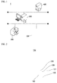
- FIG. 1 is a configuration view of the paper sheets comparison system 1 of the embodiment.
- the paper sheets comparison system 1 includes at least one main body processing apparatus 100 of a paper sheets processing apparatus, a close inspection apparatus 200, a paper sheets comparison apparatus 300 and a host server 400.
- a paper sheets processing apparatus includes a paper sheets pre-processing apparatus 5 (to be described below), and the main body processing apparatus 100.
- the main body processing apparatus 100, the close inspection apparatus 200 and the paper sheets comparison apparatus 300 are connected to a network such as a local area network (LAN) or the like.
- LAN local area network
- FIG. 2 is an exterior perspective view of the main body processing apparatus 100.
- the main body processing apparatus 100 includes a paper sheets inputter 105, a manipulator 136, a manipulation display 137, an extractor 139 and a keyboard 140, outside the apparatus.
- the manipulator 136, the manipulation display 137 and the keyboard 140 are manipulated by an operator to arbitrarily set types of the paper sheets P (types of banknotes) processed by the main body processing apparatus 100.
- the paper sheets inputter 105 receives the paper sheets P supplied by the paper sheets pre-processing apparatus 5 (to be described below). Further, the paper sheets inputter 105 is not limited to the type shown in FIG. 2 but may include a feeder guide FG (to be described below).
- separated small bundles D and batch cards (BC-2) that are pre-processed by the paper sheets pre-processing apparatus 5 may be accumulated and input into the paper sheets inputter 105.
- the main body processing apparatus 100 ejects the plurality of accumulated paper sheets one by one and inspects the paper sheets one by one.
- the main body processing apparatus 100 excludes the paper sheets P in a predetermined condition among the plurality of paper sheets P based on inspection results as excluded sheets.
- the excluded paper sheets P can be ejected from the extractor 139.
- the close inspection apparatus 200 more closely reinspects the sheets (the excluded sheets) excluded once by the main body processing apparatus 100 at a lower speed than the main body processing apparatus 100.
- the close inspection apparatus 200 transmits the reinspected result to the paper sheets comparison apparatus 300.
- the paper sheets comparison apparatus 300 stores small bundle information transmitted by the paper sheets pre-processing apparatus 5 and the inspection result of the main body processing apparatus 100 to correspond to the reinspected result of the close inspection apparatus 200.
- the host server 400 manages and accumulates the information obtained from the main body processing apparatus 100 or the close inspection apparatus 200 by the paper sheets comparison apparatus 300.
- FIG. 3 is a schematic diagram showing a schematic configuration of the paper sheets pre-processing apparatus 5 of the embodiment.
- FIG. 4 is a flowchart showing an operation of the paper sheets pre-processing apparatus 5 of the embodiment.
- the paper sheets pre-processing apparatus 5 functions as a pre-processing apparatus configured to perform pre-processing of transferring the paper sheets P to the main body processing apparatus 100.
- the paper sheets pre-processing apparatus 5 includes a bundle inputter 10, a large band remover 20, a small bundle coupler 30, a small bundle picker 40, a small band remover 50 and a small bundle accumulator 60.
- the bundle inputter 10 conveys a bundle in which the plurality of paper sheets P are bound by small bands in a predetermined number of small bundles and the small bundles are bound by a large band (step S100).
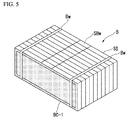
- FIG. 5 is a perspective view of a bundle B of the embodiment.
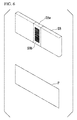
- FIG. 6 is a perspective view of a small bundle SB and the paper sheet P of the embodiment.
- the small bundle SB is a bundle obtained by binding the plurality of paper sheets P using a small band SBw.
- the small band SBw is wound in a short side direction of the paper sheets P.
- the small band SBw is a binding material such as a paper band or the like.
- a bar code SBb is adhered to the small band SBw.
- the small bundle information is information of the small bundle SB such as the strap number, the bank name, the branch name, the person in charge, the transaction date and time, or the like, that identifies the small bundle SB.
- the small bundle information may be printed on the small band SBw as characters.
- the bundle B is an object obtained by stacking ten small bundles SB in the short side direction and binding the small bundles using large bands Bw.
- a primary batch card BC-1 configured to identify the bundle B is bound in the bundle B shown in FIG. 5 together with the predetermined number of small bundles SB.
- the large bands Bw are wound in a thickness direction and a short side direction of the small bundle SB at two places.
- the large band Bw is an expandable and contractible binding material such as an elastic cord or the like.
- the bundle B is conveyed by an operator P1 to be placed on a conveyance table in the bundle inputter 10. For example, five bundles B can be placed in the bundle inputter 10.
- the bundles B placed in the bundle inputter 10 are conveyed in a conveyance path L1 (an X direction).
- the bundle inputter 10 delivers one of the bundles B conveyed to a conveyance destination position of the conveyance path L1 to a large band cutting stage ST of the large band remover 20 in a conveyance path L2 (a Y direction).
- the large band remover 20 automatically cuts the large band Bw from the bundle B as one of the bundles B is delivered (step S102).
- the large band remover 20 discards the cut large band Bw (step S104).
- the bundle B from which the large band Bw is removed is automatically conveyed along a conveyance path L3 by the small bundle coupler 30 as each of the predetermined number of small bundles SB.
- the small bundle coupler 30 couples the predetermined number of small bundles included in the plurality of bundles B as the predetermined number of small bundles SB are conveyed as each of the plurality of bundles B (step S106).
- the small bundles SB are manually input into the small bundle coupler 30 by an operator P2 with respect to the conveyance path L3.
- the small bundle coupler 30 couples the manually input small bundle SB and another small bundle SB conveyed along the conveyance path L3 as the small bundles SB are manually input (step S108).
- the small bundle picker 40 automatically separates one small bundle SB from the plurality of small bundles SB coupled by the small bundle coupler 30 (step S110).
- the small bundle picker 40 separates the one small bundle SB as the one small bundle SB is lifted in an upward direction (a Z direction).
- the small bundle picker 40 delivers the one small bundle SB that was separated to the small band remover 50 along a conveyance path L4.
- the small band remover 50 automatically cuts the small band SBw from the one small bundle SB delivered by the small bundle picker 40 (step S112).
- the small bundle SB in which the small band SBw was is becomes the separated small bundles D from which the binding is released.
- the small band remover 50 conveys one of the separated small bundles D along a conveyance path L5, and delivers the separated small bundles D of one small bundle to the small bundle accumulator 60 (step S122).
- the small band remover 50 photographs the bar code SBb of the small band SBw removed from the small bundle SB (step S114).
- the small band remover 50 photographs the bar code SBb on which small bundle information is printed, and then, discards the bar code SBb (step S116).
- the small band remover 50 analyzes an image obtained by photographing the bar code SBb and decodes the small bundle information.
- the small band remover 50 updates the decoded small bundle information (step S118).
- the small bundle accumulator 60 inserts a secondary batch card BC-2 between the separated small bundles D as the separated small bundles D of the one small bundle are delivered (step S124). Information that identifies the separated small bundles D is recorded on the secondary batch card BC-2.
- the paper sheets pre-processing apparatus 5 transmits the bar code information printed on the secondary batch card BC-2 to a banknotes processing apparatus (not shown) along with the small bundle information (step S120).
- the small bundle accumulator 60 drops the secondary batch card BC-2 and the separated small bundles D to accumulate them in a thickness direction of the paper sheets P (step S126).
- the small bundle accumulator 60 repeats the insertion of the secondary batch card BC-2 and accumulation of the separated small bundles D whenever the separated small bundles D are delivered from the small band remover 50. Further, the small bundle accumulator 60 may insert the secondary batch card BC-2 into each of the plurality of separated small bundles D. For example, the small bundle accumulator 60 may insert the secondary batch card BC-2 into each of the predetermined number of separated small bundles D included in the bundle B. The small bundle accumulator 60 accumulates the separated small bundles D of the plurality of small bundles SB, slides the accumulated separated small bundles D in a transfer direction L6, and then, transfers the separated small bundles D to the main body processing apparatus 100 of the paper sheets P (step S128).
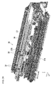
- FIG. 7 is a perspective view showing the exterior of a bundle processing system in the paper sheets pre-processing apparatus 5 of the embodiment.
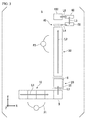
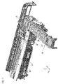
- FIG. 8 is a side view of the bundle inputter 10 in the paper sheets pre-processing apparatus 5 of the embodiment.
- the bundle inputter 10 includes a placing part 11, a conveyor belt 12, conveyor rollers 13, a lift mechanism 14 and an input stage 15.
- a plurality of placing parts 11 are installed in the X direction.
- a plurality of bundles B are placed on the placing parts 11 by the operator P1.
- the conveyor belt 12 and the conveyor rollers 13 are normally driven by a driving torque generated by a conveyor motor (not shown) to rotate the conveyor rollers 13. Accordingly, the plurality of bundles B placed on the placing parts 11 are conveyed to the input stage 15 along the conveyance path L1.
- the bundle inputter 10 when a bundle Ba at the head of the plurality of bundles B is conveyed to the input stage 15, the bundle Ba butts against a protrusion section (not shown).
- the bundle inputter 10 reversely drives the conveyor roller 13. Accordingly, the bundle Ba conveyed to the input stage 15 is separated from a bundle Bb conveyed to the front of the input stage 15. In addition, the bundle inputter 10 drives the lift mechanism 14 to raise the input stage 15. As a result, the bundle inputter 10 separates the one bundle B from the plurality of bundles B.
- FIG. 9 is a perspective view showing the large band remover 20 and the small bundle coupler 30 in the paper sheets pre-processing apparatus 5 of the embodiment.
- FIG. 10 is a side view showing the large band remover 20 and the small bundle coupler 30 in the paper sheets pre-processing apparatus 5 of the embodiment.
- the small bundle coupler 30 includes a conveyance chain 31, a first carrier 32, a second carrier 33, a conveyance rail 34 and roller tables 35 (35a and 35b).
- the large band remover 20 includes a deformation lift mechanism (a deformer) 21, a band cutter mechanism (a cutter) 22, a band removal roller (a discarder) 23 and a band clamp pin 24 (see FIG. 11 ).
- the first carrier 32 and the second carrier 33 conveys the bundle B conveyed to the input stage 15 to the large band remover 20.
- the first carrier 32 supports a side in a +Y direction of the bundle B.
- the second carrier 33 supports a side in a +Z direction of the bundle B and a side in a -Y direction of the bundle B.
- the first carrier 32 and the second carrier 33 are connected to the conveyance chain 31 and the conveyance rail 34.
- the conveyance chain 31 is provided along the conveyance path L2 from a +X side of the input stage 15 to an end portion of a +Y side of the conveyance path L3 of the small bundle coupler 30.
- the conveyance chain 31 is driven by a conveyance motor (not shown) and moves the first carrier 32 and the second carrier 33 in the ⁇ Y direction.
- the large band remover 20 removes the large band Bw from the bundle B according to conveyance of the bundle B to the predetermined large band removal position.
- the predetermined large band removal position is a position at which the deformation lift mechanism (a presser) 21 and the band cutter mechanism 22 are installed at the roller tables 35 in the Y direction.
- a side of the bundle B in the +Y direction is pressed by a support 32a (a first support) of the first carrier 32.
- an upper side of the bundle B is pressed by three claw sections 33a (second support sections) of the second carrier 33.
- a side of the bundle B in the -Y direction is pressed by a support section 33b (a first support section) of the second carrier 33.
- FIG. 11 is a side view showing a state in which the bundle B is deformed by the large band remover 20 in the paper sheets pre-processing apparatus 5 of the embodiment.
- the deformation lift mechanism (the presser) 21 raises three or four small bundles SB using three lifters 21a, 21b and 21c in a long side direction (an X direction) of the small bundle SB (see FIG. 12 ). Accordingly, the deformation lift mechanism 21 forms the space 20a between the large band Bw and the small bundle SB by deforming the bundle B. Further, a lift amount by the deformation lift mechanism 21 is set such that the space 20a is formed and a bottom surface of the small bundle SB is disposed higher than the band clamp pin 24 in the Z direction.
- FIG. 12 is a perspective view showing a state in which the band clamp pin 24 is to be inserted into the space 20a by the large band remover 20 in the paper sheets pre-processing apparatus 5 of the embodiment.
- Front end portions 24a and 24b of the band clamp pin 24 are moved toward the space 20a from both sides in the X direction. Movement of the front end portions 24a and 24b in a state in which they are opposite to each other in the space 20a is stopped. Accordingly, the band clamp pin 24 is inserted between the large band Bw and the small bundle SB.
- FIG. 13 is a perspective view showing a state in which the band clamp pin 24 is inserted into the space 20a by the large band remover 20 in the paper sheets pre-processing apparatus 5 of the embodiment.
- FIG. 14 is a side view showing a state in which the band clamp pin 24 is lowered by the large band remover 20 in the paper sheets pre-processing apparatus 5 of the embodiment.
- the large band Bw is pressed against the band removal roller 23 when the band clamp pin 24 and the band removal roller 23 abut each other.
- FIG. 15 is a perspective view showing a state in which the band cutter mechanism 22 of the large band remover 20 in the paper sheets pre-processing apparatus 5 of the embodiment is moved.
- FIG. 16 is a side view of the band cutter mechanism 22 of the paper sheets pre-processing apparatus 5 of the embodiment.
- the band cutter mechanism 22 includes an upper blade 22a and a cutting blade 22b.
- the upper blade 22a is formed at a substantially C-shaped inner wall section of the band cutter mechanism 22.
- the cutting blade 22b is disposed inside the substantially C-shaped inner wall to oppose the upper blade 22a.
- the cutting blade 22b receives a rotational torque by rotational driving of a rotation roller 22d via a pivot belt 22e.
- the cutting blade 22b is rotationally driven about a rotary shaft 22c.
- the band cutter mechanism 22 moves the cutting blade 22b in the X direction shown in FIG. 15 while rotationally driving the cutting blade 22b.
- the band cutter mechanism 22 cuts the large band Bw through rotation of the cutting blade 22b when the upper blade 22a and the cutting blade 22b come in contact with the large band Bw.
- FIG. 17 is a perspective view when the band removal roller 23 of the large band remover 20 is seen from the -Y direction side in the paper sheets pre-processing apparatus 5 of the embodiment.
- FIG. 18 is a side view showing a state in which the band removal roller 23 of the large band remover 20 is rotated in the paper sheets pre-processing apparatus 5 of the embodiment.
- the band removal roller 23 is rotated in a direction R shown by an arrow of FIG. 18 with the large band Bw interposed between the band clamp pin 24 and the band removal roller 23. Accordingly, the band removal roller 23 pulls the cut large band Bw.
- the pulled large band Bw is discharged to the outside of the apparatus or accumulated in an exclusion box to be discarded.
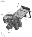
- FIG. 19 is a perspective view showing the arranger 25 of the large band remover 20 in the paper sheets pre-processing apparatus 5 of the embodiment.
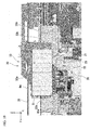
- FIG. 20 is a configuration view of a portion of the small bundle coupler 30 in the paper sheets pre-processing apparatus 5 of the embodiment.
- the small bundle coupler 30 includes a small bundle processing table 36, a pair of conveyor belts 37A and 37B, a first slider 38 and a second slider 39.
- the small bundle processing table 36 is provided along the conveyance path L3 (the Y direction).
- the predetermined number of small bundles SB are conveyed to the small bundle processing table 36 whenever the large band Bw is removed by the large band remover 20.
- the conveyor belts 37A and 37B are installed at both sides of the small bundle processing table 36 in the X direction.
- the conveyor belts 37A and 37B are disposed to come in contact with lower surfaces of the plurality of small bundles SB conveyed to the small bundle processing table 36.
- the conveyor belts 37A and 37B are driven in the Y direction by a driving torque of a driving motor (not shown).
- the conveyor belts 37A and 37B generates an auxiliary force of conveying the small bundle SB along the conveyance path L3 by a frictional force between the plurality of small bundles SB and the conveyor belts 37A and 37B.
- the first slider 38 is disposed between the small bundle processing table 36 and the conveyor belts 37A and 37B.
- the first slider 38 is moved in the Z direction and the Y direction by a moving mechanism (not shown).
- the first slider 38 protrudes from the small bundle processing table 36 in the +Z direction when the plurality of small bundles SB are conveyed along the conveyance path L3.
- the first slider 38 is moved in the Y direction based on the positions of the plurality of small bundles SB.
- the second slider 39 is disposed further on the +Y direction side than the first slider 38 and between the small bundle processing table 36 and the conveyor belts 37A and 37B.
- the second slider 39 is moved in the Y direction based on the positions of the plurality of small bundles SB.
- the second slider 39 is slid toward the -Y direction side to receive the predetermined number of small bundles SB at the beginning of a startup of the paper sheets pre-processing apparatus 5.
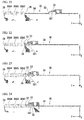
- FIGS. 21,22,23,24 , 25,26 and 27 are side views showing states in which the predetermined number of small bundles SB are coupled to each other by the small bundle coupler 30 of the paper sheets pre-processing apparatus 5 of the embodiment.
- the predetermined number of small bundles SB are the plurality of small bundles SB included in the one bundle B. As shown in FIG. 21 , the predetermined number of small bundles S#1 are pressed from both sides in the Y direction and the side in the +Z direction by the first carrier 32 and the second carrier 33 at the predetermined large band removal position. In a state in which the plurality of small bundles SB#1 are disposed at a large band removal position, the predetermined number of small bundles SB#2, SB#3 and SB#4 are coupled. The predetermined number of small bundles SB#2, SB#3 and SB#4 are pressed from the -Y direction side by the first slider 38 and pressed from the +Y direction side by the second slider 39. Further, the predetermined number of small bundles SB#2, SB#3 and SB#4 are coupled by the small bundle coupler 30, and an operation of cutting the small bundles at every small bundle using the small bundle picker 40 (to be described below) is performed.
- the small bundle coupler 30 slides the first carrier 32 and the second carrier 33 in the +Y direction in a state in which the predetermined number of small bundles SB#1 are pressed by the first carrier 32 and the second carrier 33.
- the small bundle coupler 30 slides the first carrier 32 and the second carrier 33 to a position at which the first carrier 32 overlaps the first slider 38.
- the small bundle coupler 30 lowers the first slider 38 such that a front end of the first slider 38 is disposed lower than the small bundle processing table 36.
- the small bundle coupler 30 moves the first slider 38 further to the -Y direction side than the predetermined number of small bundles SB#1 and raises the first slider 38 at a position of the -Y direction side of the second carrier 33.
- the small bundle coupler 30 raises the first carrier 32 to withdraw the first carrier 32 from between the predetermined number of small bundles SB#1 and the predetermined number of small bundles SB#2.
- the small bundle coupler 30 slides the first slider 38 toward the +Y direction side and brings the first slider 38 in contact with the -Y direction side of the predetermined number of small bundles SB#1.
- FIG. 25 the small bundle coupler 30 moves the first slider 38 further to the -Y direction side than the predetermined number of small bundles SB#1 and raises the first slider 38 at a position of the -Y direction side of the second carrier 33.
- the small bundle coupler 30 raises the first carrier 32 to withdraw the first carrier 32 from between the predetermined number of small bundles SB#1 and the predetermined number of small bundles SB#2.
- the small bundle coupler 30 couples the predetermined number of small bundles SB#1 and the predetermined number of small bundles SB#2 as the first slider 38 slides toward the +Y direction side.
- the first carrier 32 of the small bundle coupler 30 returns the first slider 38 to the large band removal position and receives the next predetermined number of small bundles SB.
- the small bundle SB is input onto the small bundle processing table 36 by a manual operation of the operator P2.
- the small bundle coupler 30 presses the first carrier 32 toward the -Y direction side of the small bundle SB on the small bundle processing table 36 in a state shown in FIG. 26 according to manipulation by a manual input button (not shown).
- the small bundle coupler 30 lowers the first slider 38 to be lower than the small bundle processing table 36.
- the small bundle coupler 30 adjusts a driving torque in the +Y direction of the first carrier 32 to become a pressing force capable of manually moving the first carrier 32 in the -Y direction.
- the first carrier 32 is slid toward the -Y direction side by the operator P2 to add an additional small bundle SB to the -Y direction side of the coupled small bundles SB.
- the first carrier 32 is gradually slid toward the +Y direction side to be pressed against the -Y direction side of the coupled small bundles SB.
- the small bundle coupler 30 disposes the first slider 38 at the -Y direction side of the coupled small bundles SB while the first carrier 32 is returned to the large band removal position as the manual input button is manipulated again.
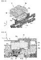
- FIG. 28 is a perspective view showing the exterior of the small bundle processing system of the paper sheets pre-processing apparatus 5 of the embodiment.
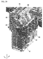
- FIG. 29 is a perspective view of the small bundle picker 40 of the paper sheets pre-processing apparatus 5 of the embodiment.
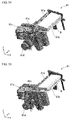
- FIG. 30 is a side view of the small bundle picker 40 of the paper sheets pre-processing apparatus 5 of the embodiment.
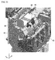
- FIG. 31 is a partially enlarged perspective view of the small bundle picker 40 of the paper sheets pre-processing apparatus 5 of the embodiment.
- the small bundle processing system includes the small bundle picker 40 and the small band remover 50.
- the small bundle picker 40 receives the plurality of small bundles SB from the small bundle coupler 30 in a state in which the plurality of small bundles SB are coupled in a thickness direction.
- the small bundle picker 40 separates a small bundle SB down from the plurality of small bundles SB.
- the small bundle picker 40 includes a plurality of timing belts 41, a plurality of round belts 42, a guide 43, a small bundle lifter 44, a small bundle conveyance table 45 and a first sweeper 46.
- Three timing belts 41 are arranged in parallel in a long side direction of the small bundle SB, and the small bundle SB at the head of the plurality of small bundles SB coupled by the small bundle coupler 30 is pressed in the +Y direction.
- Three round belts 42 are belts having a round cross section and are disposed in parallel in the long side direction of the small bundle SB.
- the round belts 42 are provided to be separated from each other in the Y direction by substantially the same thickness of the timing belts 41 and the small bundle SB as the one small bundle. Further, the round belts 42 may be moved by a mechanism moved in the thickness direction of the small bundle SB.
- the timing belts 41 and the round belts 42 are driven such that the small bundle SB is removed by a driving motor (not shown) thereabove.
- the timing belt 41 removes the one small bundle SB using a frictional force between the timing belt 41 and the small bundle SB.
- the round belt 42 conveys the one small bundle SB removed by the timing belts 41 upward while the one small bundle SB is sandwiched between the round belt 42 and the timing belt 41.
- the small bundle lifter 44 is pivoted by a lifter driver 44a as a sensor (not shown) detects the conveyance of the small bundle SB to a predetermined delivery position.
- the small bundle lifter 44 stops at a predetermined small bundle reception position and supports the small bundle SB sandwiched between the timing belts 41 and the round belts 42 at the +Z direction side.
- the small bundle lifter 44 pivots to raise the small bundle SB using the front end portion, and conveys the small bundle SB to the small bundle conveyance table 45 along the guide 43. Accordingly, the posture of the one small bundle SB is varied from a vertically placed state to a horizontally placed state and the one small bundle SB is isolated on the small bundle conveyance table 45.
- FIG. 32 is a perspective view showing a state in which the small bundle SB is conveyed by the first sweeper 46 of the small bundle picker 40 in the paper sheets pre-processing apparatus 5 of the embodiment.
- the small bundle conveyance table 45 and the end portion in the Z direction of the first sweeper 46 is preferably a core structure configured to prevent the paper sheets P from being dropped.
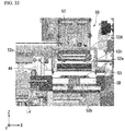
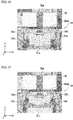
- FIG. 33 is a front view of the small band remover 50 of the paper sheets pre-processing apparatus 5 of the embodiment.
- FIG. 34 is a perspective view of the small band remover 50 of the paper sheets pre-processing apparatus 5 of the embodiment.
- the small band remover 50 includes a small bundle press 52, a small band cutter 53 and a small band picker 54.
- the small bundle press 52 includes a press arm 52A, both-end pressers 52a, a press stand 52b and a central presser 52c.
- the one small bundle SB conveyed by the first sweeper 46 is placed on the press stand 52b.
- the small bundle press 52 is disposed on the small bundle SB by a moving mechanism (not shown) when the small band SBw is removed.
- the press arm 52A is lowered by the moving mechanism such that the both-end pressers 52a come in contact with both ends of the upper surface of the small bundle SB in the X direction.
- the central presser 52c is lowered to press a substantially central portion of the small bundle SB. In this state, the small bundle press 52 presses the one small bundle SB conveyed to the press stand 52b, by the central presser 52c from an upper side toward a lower side.
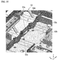
- FIG. 35 is a perspective view of the small band cutter 53 of the small band remover 50 in the paper sheets pre-processing apparatus 5 of the embodiment.
- the small band cutter 53 includes a main body section 53A at which a small bundle opposite surface 53a is formed, and a cutter 53b.
- the small band cutter 53 operates such that the main body section 53A is raised in the +X direction before the small bundle SB is conveyed to the press stand 52b. Accordingly, the small band cutter 53 exposes the small bundle opposite surface 53a.
- the small band cutter 53 causes the small bundle opposite surface 53a to oppose the side surface of the small bundle SB in a state in which the small bundle SB is placed on the press stand 52b.
- the small band cutter 53 slides the cutter 53b accommodated in the main body section 53A in the X direction to expose the cutter 53b from the small bundle opposite surface 53a when the small band SBw is to be removed.
- the small band cutter 53 slides the cutter 53b in the X direction.
- a range in the X direction in which the cutter 53b is slid is set to include a winding position of the small band SBw in a state in which the small bundle SB is placed on the press stand 52b.
- the small band cutter 53 is lowered when the separated small bundles D are conveyed after the cutter 53b is accommodated in the main body section 53A.
- the small bundle press 52 presses the small bundle SB with a press to stabilize a behavior of the small band SBw when the small band SBw is removed by the small band cutter 53.
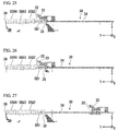
- FIGS. 36, 37 , 38 and 39 are plan views showing an operation of the small band picker 54 of the small band remover 50 in the paper sheets pre-processing apparatus 5 of the embodiment.
- the small band picker 54 separates the small band SBw cut by the small band cutter 53 from the small bundle SB. As shown in FIG. 36 , the small band picker 54 is disposed at an opposite side of the small band cutter 53 in the short side direction of the small bundle SB.
- the small band picker 54 includes a first picker claw 54a, a second picker claw 54b, a first cam 54c and a second cam 54d.
- the first picker claw 54a is connected to the first cam 54c.
- the second picker claw 54b is connected to the second cam 54d.
- the first picker claw 54a and the first cam 54c are disposed to oppose the second picker claw 54b and the second cam 54d in the X direction via a photographing stage 51c.
- the first cam 54c is driven by a driving mechanism (not shown), and performs an operation of linearly moving the first picker claw 54a in the Y direction and an operation of pivoting the front end portion of the first picker claw 54a.
- the second cam 54d is driven by a driving mechanism (not shown), and performs an operation of linearly moving the second picker claw 54b in the Y direction and an operation of pivoting the front end portion of the second picker claw 54b.
- the small bundle press 52 When the small band SBw is separated from the small bundle SB by the small band picker 54, the small bundle press 52 preferably presses the small bundle SB with a pressure to prevent the paper sheets P from being extracted from the small bundle SB. In addition, in the small bundle press 52, in order to easily hook the small band SBw by the small band picker 54, it is preferable to cause the small band SBw to deviate from the small bundle SB at a predetermined amount by the central presser 52c. In a state in which the small bundle SB is pressed by the both-end pressers 52a of the small bundle press 52, as shown in FIG. 36 , a portion SBw# of the small band picker 54 side of the small band SBw is bent in the -Y direction with respect to the small bundle SB.
- the small band picker 54 moves the front end portions of the first picker claw 54a and the second picker claw 54b in the Y direction using the first cam 54c and the second cam 54d after the small band SBw is cut by the small band cutter 53.
- the first cam 54c and the second cam 54d pivot the front end portions of the first picker claw 54a and the second picker claw 54b as the posture thereof is deviated from the Y direction to the X direction.
- the first cam 54c and the second cam 54d are operated such that the lengthwise direction thereof is parallel to the long side direction of the small bundle SB, and further, pivot the first picker claw 54a and the second picker claw 54b.
- the first picker claw 54a and the second picker claw 54b are disposed parallel to the long side direction of the small bundle SB, and the front end portions are disposed to oppose each other in the portion SBw# of the small band SBw.
- the first cam 54c and the second cam 54d slide the first picker claw 54a and the second picker claw 54b in the -Y direction as the first cam 54c and the second cam 54d are moved in the -Y direction.
- the small band SBw is hooked by the front end portions at the -Y direction side and the small band SBw is pulled off the small bundle SB.
- the small bundle press 52 is preferably pressed from above the small bundle SB with a pressure to prevent the paper sheets P from being extracted in an operation in which the small band SBw is pulled off the small bundle SB.
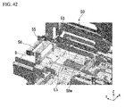
- FIGS. 40, 41 and 42 are views showing an operation of a second sweeper 55 of the small band remover 50.
- FIG. 40 is a perspective view showing the second sweeper 55 of the small band remover 50 in the paper sheets pre-processing apparatus 5 of the embodiment.
- FIG. 41 is a plan view showing the second sweeper 55 of the small band remover 50 in the paper sheets pre-processing apparatus 5 of the embodiment.
- FIG. 42 is a perspective view showing an operation of the second sweeper 55 of the small band remover 50 in the paper sheets pre-processing apparatus 5 of the embodiment.
- FIG. 43 is a plan view showing an operation of the second sweeper 55 of the small band remover 50 in the paper sheets pre-processing apparatus 5 of the embodiment.
- the small band remover 50 includes the second sweeper 55 and a separated small bundles conveyance table 56.
- the second sweeper 55 conveys the small bundles separated by pulling the small band SBw off the small bundle SB by the small band picker 54 to the separated small bundles conveyance table 56.
- the second sweeper 55 includes a second sweeper arm 55a.
- the second sweeper arm 55a has an L shape when seen in the X direction.
- the second sweeper arm 55a presses the separated small bundles D from an upper side using a portion parallel to the Y direction in a state in which the separated small bundles D are moved.
- the second sweeper arm 55a supports the separated small bundles D from the -Y direction using a portion parallel to the Z direction in a state in which the separated small bundles D are conveyed.
- the small band cutter 53 lowers the main body section 53A before the separated small bundles D are conveyed by the second sweeper 55. Accordingly, the upper surface of the main body section 53A disposes substantially the same position in the Z direction as the separated small bundles conveyance table 56. Further, the upper surface of the main body section 53A, the separated small bundles conveyance table 56 and the end portion of the -Z direction side of the second sweeper arm 55a preferably become a core structure configured to prevent the paper sheets P from dropping from the separated small bundles D.
- the second sweeper 55 disposed the second sweeper arm 55a at the -Y direction side of the separated small bundles D, and then, as shown in FIG. 42 , slides the second sweeper arm 55a toward the +Y direction side. Accordingly, the second sweeper 55 conveys the separated small bundles D along the conveyance path L5 (the Y direction).
- the second sweeper 55 causes the separated small bundles D to pass over the main body section 53A to be conveyed onto the separated small bundles conveyance table 56.
- the second sweeper 55 separates the small band SBw from the separated small bundles D.
- the small band picker 54 further moves the first cam 54c and the second cam 54d in the -Y direction and conveys the small band SBw to a position on the predetermined photographing stage 51c.
- FIGS. 43,44 and 45 are views showing an operation of a third sweeper 57 of the small band remover 50.
- FIG. 43 is a perspective view showing the third sweeper 57 of the small band remover 50 in the paper sheets pre-processing apparatus 5 of the embodiment.
- FIG. 44 is a perspective view showing an operation of the third sweeper 57 of the small band remover 50 in the paper sheets pre-processing apparatus 5 of the embodiment.
- FIG. 45 is a perspective view showing another operation of the second sweeper 55 of the small band remover 50 in the paper sheets pre-processing apparatus 5 of the embodiment.
- the small band remover 50 includes the third sweeper 57.
- the third sweeper 57 discharges the separated small bundles D conveyed by the second sweeper 55 from the separated small bundles conveyance table 56.
- the third sweeper 57 includes a plurality of claw sections 57a, 57b and 57c.
- the claw sections 57a, 57b and 57c are connected to a movable guide (not shown) and raised or lowered (withdrawn) by a vertical operation of the movable guide.
- the claw sections 57a, 57b and 57c are raised as the separated small bundles D are conveyed to a predetermined position on the separated small bundles conveyance table 56 by the second sweeper 55. Accordingly, the claw sections 57a, 57b and 57c are exposed from the upper surface of the separated small bundles conveyance table 56 and disposed at the -Y direction side of the separated small bundles D.
- the third sweeper 57 moves the claw sections 57a, 57b and 57c in the Y direction. Accordingly, the claw sections 57a, 57b and 57c support the side surface in the -Y direction side of the separated small bundles D and convey the side surface to the +Y direction side. As a result, the claw sections 57a, 57b and 57c discharge the separated small bundles D from the separated small bundles conveyance table 56.
- the separated small bundles D freely drop onto a position (a small bundle discharge position Pb) by being pushed off the separated small bundles conveyance table 56.
- the third sweeper 57 is withdrawn and lowered to a position before the discharge of the separated small bundles D.
- the second sweeper 55 moves in the -Y direction and is withdrawn to convey the next separated small bundle D.
- the small band cutter 53 raises the main body section 53A to cut the small band SBw of the next small bundle SB when the claw sections 57a, 57b and 57c are raised.
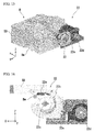
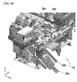
- FIG. 46 is a perspective view showing a state in which the bar code SBb is read by the small band remover 50 in the paper sheets pre-processing apparatus 5 of the embodiment.
- FIG. 47 is a plan view showing a state in which the bar code SBb is read by the small band remover 50 in the paper sheets pre-processing apparatus 5 of the embodiment.
- FIG. 48 is a perspective view showing a state in which the small band SBw is discarded by the small band remover 50 in the paper sheets pre-processing apparatus 5 of the embodiment.
- FIG. 49 is a plan view showing a state in which the small band SBw is discarded by the small band remover 50 in the paper sheets pre-processing apparatus 5 of the embodiment.
- the small band remover 50 includes image capturers 51a and 51b, the photographing stage 51c and a small band discharger 58. As shown in FIG. 46 , the small band SBw is separated from the separated small bundles D and conveyed in the -Y direction by the small band picker 54. Accordingly, as shown in FIG. 47 , the small band SBw is conveyed onto the photographing stage 51c.
- the photographing stage 51 c is a transparent plate-shaped member.
- the photographing stage 51 c is included in a photographing range 51 d by the image capturers 51 a and 51b.
- the image capturers 51a and 51b photograph the small band SBw from above and below according to conveyance of the small band SBw to the photographing stage 51c.
- the image capturers 51 a and 51b generate image information of the photographed bar code SBb.
- the image capturers 51 a and 51b analyze the generated image information and generate small bundle information (information reader).
- the small band discharger 58 includes a small band removal roller 58a and a small band discharge guide 58b.
- the small band removal roller 58a is installed at the -Y direction side of the photographing stage 51c.
- the small band removal roller 58a the X direction of which becomes a lengthwise direction, has a tandem form.
- the small band removal roller 58a is rotationally driven in the -Y direction by a driving mechanism (not shown) around the X direction serving as an axis of rotation. After the bar code SBb is photographed, the small band SBw is conveyed to the small band removal roller 58a by the small band picker 54.
- the small band removal roller 58a rolls up the small band SBw conveyed by the rotation operation to send the small band SBw to the -Y direction side.
- the small band discharge guide 58b receives the small band SBw sent by the small band removal roller 58a as shown in FIG. 49 and discharges the small band SBw to the outside as shown in FIG. 48 .
- FIG. 50 is an exterior view of a small bundle accumulation processing system of the paper sheets pre-processing apparatus 5 of the embodiment.
- FIG. 51 is a schematic diagram of the main body processing apparatus 100 of the embodiment.
- the separated small bundles D discharged by the small band remover 50 are accumulated at a small bundle accumulation position Pc by the small bundle accumulator 60.
- the paper sheets P are transferred to the X direction side (a forward direction of FIG. 51 ) in a state in which the paper sheets P of the processing target are accumulated.
- the main body processing apparatus 100 accumulates the transferred paper sheets P on the feeder guide FG.
- the feeder guide FG is inclined by a predetermined angle ⁇ with respect to the Z direction to accumulate the plurality of paper sheets P.
- the plurality of paper sheets P accumulated on the feeder guide FG are ejected one by one to be sent to a conveyance path.
- the feeder guide FG may be a portion of a reception mechanism of the separated small bundles D of an accumulated sheet supply 112 of the main body processing apparatus 100 (to be described below).
- the small bundle accumulator 60 includes a small bundle shutter 61, a small bundle press 62, a small bundle accumulation support 63, a small bundle transferor 64, an arranger 65, a transfer driver 66 and a card stacker 67.
- FIG. 52 is a perspective view of the card stacker 67 of the paper sheets pre-processing apparatus 5 of the embodiment.
- the card stacker 67 inserts the secondary batch card BC-2 into each of the separated small bundles D to identify the separated small bundles D from which the small band SBw is removed.
- a bar code BCb on which strap numbers for identifying the separated small bundles D are encoded is printed on the secondary batch card BC-2.
- the card stacker 67 includes a card stacker 67a, a card conveyer 67b, a feed controller 67c, a bar code reader 67d and a support driver 67e.
- the card stacker 67a accommodates a plurality of secondary batch cards BC-2 such that a printing surface of the bar code BCb of the secondary batch card BC-2 is in the +Z direction.
- the card stacker 67a has an uplift structure configured to uplift a new secondary batch card BC-2 in the +Z direction and supply the new secondary batch card BC-2 into the card conveyer 67b whenever a secondary batch card BC-2 is discharged.
- the card conveyer 67b includes two driving motors 67b-1 and 67b-2 and rubber rollers (not shown). The rubber rollers sandwich an upper surface and a lower surface of the secondary batch card BC-2.
- the card conveyer 67b rotatably drives the rubber rollers using the driving forces of the driving motors 67b-1 and 67b-2 and conveys the secondary batch card BC-2 uplifted by the card stacker 67a in the X direction.
- the card conveyer 67b conveys and discharges the secondary batch card BC-2 before dropping timing of the separated small bundles D.
- the bar code reader 67d reads the bar code BCb printed on the conveyed secondary batch card BC-2 by the bar code reader 67d.
- the bar code reader 67d decodes the bar code BCb based on the read image information and generates bar code information such as a strap number or the like.
- the support driver 67e has a driving motor (not shown) and drives the small bundle accumulation support 63 in the Z direction.
- the feed controller 67c controls a pressing force on the secondary batch card BC-2 using the rubber rollers.
- the feed controller 67c drives a driving motor (not shown) to control the support driver 67e.
- the secondary batch card BC-2 is conveyed to a reading region of the bar code reader 67d under control of the feed controller 67c.
- the secondary batch card BC-2 is discharged to the small bundle shutter 61 after the bar code information is read.
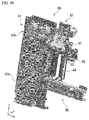
- FIG. 53 is a perspective view of the small bundle shutter 61 of the paper sheets pre-processing apparatus 5 of the embodiment.
- FIGS. 54, 55 and 56 are perspective views showing an operation of the small bundle shutter 61 of the paper sheets pre-processing apparatus 5 of the embodiment.
- the small bundle shutter 61 catches the separated small bundles D freely dropped on the small bundle discharge position Pb.
- the small bundle shutter 61 includes an upper shutter tray 61 a, a lower shutter tray 61 b, a tray driver 61c, a driving motor 61d and a tray withdrawer 61e.
- the upper shutter tray 61 a is disposed under the small bundle discharge position Pb.
- the upper shutter tray 61a is a reception surface configured to receive the separated small bundles D dropped by the small band remover 50.
- the reception surface of the upper shutter tray 61 a is a horizontal surface (an XY plane) perpendicular to a dropping direction of the separated small bundles D.
- the tray driver 61c is driven by the driving motor 61d and the reception surface is the XY plane.
- the lower shutter tray 61b is installed at the -Z direction side of the upper shutter tray 61a.
- the end portions in the +X direction of the upper shutter tray 61 a and the lower shutter tray 61 b are connected by a hinge mechanism. Accordingly, the upper shutter tray 61 a is switched between a state in which the upper shutter tray 61a is inclined with respect to the lower shutter tray 61b (see FIG. 53 ) and a state in which the upper shutter tray 61a comes in contact with the lower shutter tray 61b (see FIG. 54 ).
- the tray driver 61 c supports a place of the upper shutter tray 61 a opposite to a place connected to the lower shutter tray 61b in the X direction.
- the tray driver 61c is driven to switch a positional relation between the upper shutter tray 61 a and the lower shutter tray 61 b to the inclined state and the contacted state.
- the tray driver 61c adjusts an inclined angle of the upper shutter tray 61a as the driving motor 61 d is driven by a controller (not shown).
- the tray withdrawer 61 e has a driving mechanism (not shown) and moves the upper shutter tray 61 a and the lower shutter tray 61b in the X direction.
- the tray withdrawer 61e moves the upper shutter tray 61a in the +X direction side as shown in FIGS. 53 and 54 when the separated small bundles D are received by the upper shutter tray 61a.
- the tray withdrawer 61 e withdraws the upper shutter tray 61 a in the -X direction as shown in FIG. 55 when the separated small bundles D are delivered to the small bundle accumulation support 63 by the upper shutter tray 61 a.
- the small bundle shutter 61 disposes the upper shutter tray 61a and the lower shutter tray 61b at the +X direction side as shown in FIG. 54 in a standby state of the separated small bundles D.
- the secondary batch card BC-2 is conveyed onto the upper shutter tray 61 a from the Y direction side by the card stacker 67.
- the separated small bundles D pushed out in the +Y direction by the third sweeper 57 of the small band remover 50 are dropped onto the upper shutter tray 61a.
- the upper shutter tray 61a receives the separated small bundles D as shown in FIG. 54 when the separated small bundles D are dropped.
- the tray driver 61c is switched to the state in which the upper shutter tray 61 a comes in contact with the lower shutter tray 61b. Accordingly, the separated small bundles D are inclined by a predetermined angle from a horizontal surface. As shown in FIG. 56 , next, the tray withdrawer 61e withdraws the upper shutter tray 61a and the lower shutter tray 61 b and drops the separated small bundles D and the secondary batch card BC-2. The small bundle shutter 61 accumulates the separated small bundles D on the small bundle accumulation support 63 as the operation is repeated.
- FIG. 57 is a perspective view of the small bundle press 62 of the paper sheets pre-processing apparatus 5 of the embodiment.
- FIGS. 58, 59 and 60 are perspective views showing an operation of the small bundle press 62 of the paper sheets pre-processing apparatus 5 of the embodiment.
- the small bundle press 62 supports a behavior of the separated small bundles D that are dropped when the separated small bundles D are accumulated.
- the small bundle press 62 includes a press arm 62a, a positioning shaft 62b, an electromagnetic clutch 62c and a vertically operated motor 62d.
- the press arm 62a holds the paper sheets P to prevent droppage thereof when the separated small bundles D are dropped.
- the press arm 62a has front end portions 62a-1 and 62a-2 configured to abut the side surfaces in the +X direction of the separated small bundles D at both ends in the Y direction.
- the positioning shaft 62b becomes a core structure with the upper shutter tray 61a and the lower shutter tray 61b in the X direction.
- the electromagnetic clutch 62c transmits power generated by the vertically operated motor 62d and moves the press arm 62a in an upward direction (the +Z direction).
- the small bundle press 62 disposes the press arm 62a at a predetermined position on the small bundle shutter 61 in the standby state in which the separated small bundles D does not drop on the upper shutter tray 61 a.
- the vertically operated motor 62d transmits a driving torque to support the press arm 62a via the electromagnetic clutch 62c.
- the small bundle press 62 blocks power transmission of the electromagnetic clutch 62c when the separated small bundles D drop on the upper shutter tray 61 a, and the upper shutter tray 61a and the lower shutter tray 61 b come in contact as shown in FIG. 58 . Then, as shown in FIG. 59 , the press arm 62a drops on the separated small bundles D.
- the press arm 62a drops together with the separated small bundles D and the secondary batch card BC-2. Accordingly, the press arm 62a prevents the paper sheets P from dropping from the separated small bundles D.
- the small bundle press 62 functions as a stopper of the separated small bundles D discharged from the small band remover 50 by the front end portions 62a-1 and 62a-2 of the press arm 62a.
- the press arm 62a drops together with the separated small bundles D and is supported by the small bundle accumulation support 63.
- the press arm 62a is raised to a predetermined position on the upper shutter tray 61 a after the press arm 62a drops on the small bundle accumulation support 63 and before the separated small bundles D drop on the upper shutter tray 61a. Accordingly, the small bundle press 62 accumulates the plurality of separated small bundles D on the small bundle accumulation support 63.
- FIG. 61 is a perspective view showing the arranger 65 of the small bundle accumulator 60 of the paper sheets pre-processing apparatus 5 of the embodiment.
- the arranger 65 arranges positions of the separated small bundles D freely dropped on the small bundle transferor 64.
- the arranger 65 has a contact surface 65a formed in the -X direction of the small bundle transferor 64.
- the arranger 65 brings the contact surface 65a in contact with the separated small bundles D and the secondary batch card BC-2 in the small bundle transferor 64 using a driving mechanism (not shown) such as a solenoid or the like.
- the arranger 65 modifies positions of the separated small bundles D and the secondary batch card BC-2 in the small bundle transferor 64 using vibrations.
- FIG. 62 is a perspective view showing the small bundle accumulation support 63 and the small bundle transferor 64 of the small bundle accumulator 60 in the paper sheets pre-processing apparatus 5 of the embodiment.
- the small bundle accumulation support 63 is moved in a vertical direction in the small bundle transferor 64 by the support driver 67e.
- the small bundle accumulation support 63 becomes a core structure with the small bundle transferor 64 in the Y direction.
- the small bundle accumulation support 63 lowers the separated small bundles D from an upper end position by a predetermined distance shown in FIG. 62 by catching the separated small bundles D.
- the small bundle accumulation support 63 catches the predetermined number (for example, ten) of separated small bundles D and the secondary batch card BC-2.
- the small bundle accumulation support 63 delivers the predetermined number of separated small bundles D and the secondary batch card BC-2 to the small bundle transferor 64.
- the small bundle accumulation support 63 slides, for example, in the -X direction to be accommodated in the card stacker 67 in a state in which the predetermined number of separated small bundles D and the secondary batch card BC-2 are accumulated. Afterward, the small bundle accumulation support 63 is raised to the upper end position and disposed at the upper end position under the small bundle shutter 61 again.
- FIG. 63 is a perspective view showing the small bundle transferor 64 and the transfer driver 66 of the small bundle accumulator 60 in the paper sheets pre-processing apparatus 5 of the embodiment.
- the small bundle transferor 64 delivers the predetermined number of separated small bundles D from the small bundle accumulation support 63.
- the small bundle transferor 64 supports both sides in the X direction and the +Y direction side of the separated small bundles D and the lower surface of the separated small bundles D.
- the small bundle transferor 64 is moved in the X direction by the transfer driver 66.
- the transfer driver 66 includes a transfer connecting section 66a, a support stage 66b, a driver 66c, a driving motor 66d and a slide rail 66e.
- the transfer connecting section 66a connects a lower portion of the small bundle transferor 64 and the support stage 66b.
- the support stage 66b has an upper surface connected to the small bundle transferor 64 by the transfer connecting section 66a, and a lower surface in which a concave rail reception section (not shown) assembled with the slide rail 66e is formed.
- the driver 66c includes a transfer belt 66c-1, a driving roller 66c-2 and a connecting section 66c-3.
- the driving roller 66c-2 is operated to receive a driving torque generated by the driving motor 66d and send the driving torque to the transfer belt 66c-1.
- the connecting section 66c-3 is connected to a lower portion of the support stage 66b.
- the connecting section 66c-3 moves the support stage 66b along the slide rail 66e using a sending operation of the transfer belt 66c-1.
- the transfer driver 66 is in a standby state in which the small bundle transferor 64 is disposed as described in FIG. 63 until the predetermined number of separated small bundles D and the secondary batch card BC-2 are accumulated.
- the transfer driver 66 slides the small bundle transferor 64 in the +X direction as the predetermined number of separated small bundles D and the secondary batch card BC-2 are accumulated.
- the transfer driver 66 slides the small bundle transferor 64 to a position at which the accumulated sheet supply 112 (the feeder guide FG) of the main body processing apparatus 100 is present.
- a feeder paddle becomes a core structure with the small bundle transferor 64.
- the feeder paddle receives the predetermined number of separated small bundles D and the secondary batch card BC-2 accumulated on the small bundle transferor 64, and installs the separated small bundles D and the secondary batch card BC-2 at the accumulated sheet supply 112 (the feeder guide FG) of the main body processing apparatus 100.
- the small bundle information that has decoded the strap number and the bar code SBb read by the secondary batch card BC-2 is stored in, for example, a storage (not shown) by an internal computer of the paper sheets pre-processing apparatus 5.
- the small bundle information that has decoded the stored strap number and bar code SBb is sent to the paper sheets comparison apparatus 300.
- the large band remover 20 configured to remove the large band Bw from the bundle B
- the small bundle picker 40 configured to remove the small band SBw from the small bundle SB
- the small bundle accumulator 60 configured to accumulate the plurality of paper sheets P, from which the small band SBw is removed, in a thickness direction
- a burden of removal of removal and the small band SBw of the large band Bw in the pre-processing in which the paper sheets P are input into the main body processing apparatus 100 can be reduced.
- removal of the large band Bw and removal of the small band SBw can be automatically performed, a waiting time in which the paper sheets P are input can be reduced with no necessity of stoppage of the pre-processing.
Abstract
Description
- Embodiments described herein relate generally to a paper sheets pre-processing apparatus.
- In order to inspect paper sheets loaded by a bundle unit in which a plurality of paper sheets are bound by small bands and the small bundles are arranged and bound in a predetermined number by a large band using a paper sheets inspection apparatus for every sheet, pre-processing of removing the large band and then removing the small bands should be performed. However, since the manpower of an operator is required for removal of the large band and removal of the small bands, much time and effort is required to input the paper sheets into a main body processing apparatus for the paper sheets. In order to solve this problem, the present invention provides a paper sheets pre-processing apparatus capable of reducing the burden in pre-processing of paper sheets.
-
-
FIG. 1 is a configuration view of a papersheets comparison system 1 of an embodiment. -
FIG. 2 is an exterior perspective view of a mainbody processing apparatus 100 in the papersheets comparison system 1 of the embodiment. -
FIG. 3 is a schematic diagram showing a schematic configuration of a paper sheets pre-processingapparatus 5 of the embodiment. -
FIG. 4 is a flowchart showing an operation of the paper sheets pre-processingapparatus 5 of the embodiment. -
FIG. 5 is a perspective view of a bundle B according to the embodiment. -
FIG. 6 is a perspective view of a small bundle SB and paper sheets P according to the embodiment. -
FIG. 7 is a perspective view showing the exterior of a bundle processing system in the paper sheets pre-processingapparatus 5 according to the embodiment. -
FIG. 8 is a side view of abundle inputter 10 in the paper sheets pre-processingapparatus 5 of the embodiment. -
FIG. 9 is a perspective view showing alarge band remover 20 and asmall bundle coupler 30 in the paper sheets pre-processingapparatus 5 of the embodiment. -
FIG. 10 is a side view showing thelarge band remover 20 and thesmall bundle coupler 30 in the paper sheets pre-processingapparatus 5 of the embodiment. -
FIG. 11 is a side view showing a state in which the bundle B is deformed by thelarge band remover 20 of the paper sheets pre-processingapparatus 5 of the embodiment. -
FIG. 12 is a perspective view showing a state in which aband clamp pin 24 is to be inserted into a space 20a by thelarge band remover 20 of the paper sheets pre-processingapparatus 5 of the embodiment. -
FIG. 13 is a perspective view showing a state in which theband clamp pin 24 is inserted into the space 20a by thelarge band remover 20 of the paper sheets pre-processingapparatus 5 of the embodiment. -
FIG. 14 is a side view showing a state in which theband clamp pin 24 is lowered by thelarge band remover 20 of the paper sheets pre-processingapparatus 5 of the embodiment. -
FIG. 15 is a perspective view showing a state in which aband cutter mechanism 22 of thelarge band remover 20 of the paper sheets pre-processingapparatus 5 of the embodiment is moved. -
FIG. 16 is a side view of theband cutter mechanism 22 of the paper sheets pre-processingapparatus 5 of the embodiment. -
FIG. 17 is a perspective view when aband removal roller 23 of thelarge band remover 20 is seen from a -Y direction side in the paper sheets pre-processingapparatus 5 of the embodiment. -
FIG. 18 is a side view showing a state in which theband removal roller 23 of thelarge band remover 20 in the paper sheets pre-processingapparatus 5 of the embodiment is rotated. -
FIG. 19 is a perspective view showing anarranger 25 of thelarge band remover 20 in the paper sheets pre-processingapparatus 5 of the embodiment. -
FIG. 20 is a configuration view of a portion of thesmall bundle coupler 30 in the paper sheets pre-processingapparatus 5 of the embodiment. -
FIG. 21 is a side view showing a state in which a predetermined number of small bundles SB are coupled to each other by thesmall bundle coupler 30 in the paper sheets pre-processingapparatus 5 of the embodiment. -
FIG. 22 is a side view showing a state in which the predetermined number of small bundles SB are coupled to each other by thesmall bundle coupler 30 in the paper sheets pre-processingapparatus 5 of the embodiment. -
FIG. 23 is a side view showing a state in which the predetermined number of small bundles SB are coupled to each other by thesmall bundle coupler 30 in the paper sheets pre-processingapparatus 5 of the embodiment. -
FIG. 24 is a side view showing a state in which the predetermined number of small bundles SB are coupled to each other by thesmall bundle coupler 30 in the paper sheets pre-processingapparatus 5 of the embodiment -
FIG. 25 is a side view showing a state in which the predetermined number of small bundles SB are coupled to each other by thesmall bundle coupler 30 in the paper sheets pre-processingapparatus 5 of the embodiment. -
FIG. 26 is a side view showing a state in which the predetermined number of small bundles SB are coupled to each other by thesmall bundle coupler 30 in the paper sheets pre-processingapparatus 5 of the embodiment. -
FIG. 27 is a side view showing a state in which the predetermined number of small bundles SB are coupled to each other by thesmall bundle coupler 30 in the paper sheets pre-processingapparatus 5 of the embodiment. -
FIG. 28 is a perspective view showing the exterior of a small bundle processing system in the paper sheets pre-processingapparatus 5 of the embodiment. -
FIG. 29 is a perspective view of asmall bundle picker 40 in the paper sheets pre-processingapparatus 5 of the embodiment. -
FIG. 30 is a side view of thesmall bundle picker 40 in the paper sheets pre-processingapparatus 5 of the embodiment. -
FIG. 31 is a partially enlarged perspective view of thesmall bundle picker 40 in the paper sheets pre-processingapparatus 5 of the embodiment. -
FIG. 32 is a perspective view showing a state in which the small bundle SB is conveyed by afirst sweeper 46 of thesmall bundle picker 40 in the paper sheets pre-processingapparatus 5 of the embodiment. -
FIG. 33 is a front view of asmall band remover 50 in the paper sheets pre-processingapparatus 5 of the embodiment. -
FIG. 34 is a perspective view of thesmall band remover 50 of the paper sheets pre-processingapparatus 5 of the embodiment. -
FIG. 35 is a perspective view of asmall band cutter 53 of thesmall band remover 50 in the paper sheets pre-processingapparatus 5 of the embodiment. -
FIG. 36 is a plan view showing an operation of asmall band picker 54 of thesmall band remover 50 in the paper sheets pre-processingapparatus 5. -
FIG. 37 is a plan view showing the operation of thesmall band picker 54 of thesmall band remover 50 in the paper sheets pre-processingapparatus 5. -
FIG. 38 is a plan view showing the operation of thesmall band picker 54 of thesmall band remover 50 in the paper sheets pre-processingapparatus 5. -
FIG. 39 is a plan view showing the operation of thesmall band picker 54 of thesmall band remover 50 in the paper sheets pre-processingapparatus 5. -
FIG. 40 is a perspective view showing asecond sweeper 55 of thesmall band remover 50 in the paper sheets pre-processingapparatus 5 of the embodiment. -
FIG. 41 is a plan view showing thesecond sweeper 55 of thesmall band remover 50 in the paper sheets pre-processingapparatus 5 of the embodiment. -
FIG. 42 is a perspective view showing an operation of thesecond sweeper 55 of thesmall band remover 50 in the paper sheets pre-processingapparatus 5 of the embodiment. -
FIG. 43 is a perspective view showing a third sweeper 57 of thesmall band remover 50 in the paper sheets pre-processingapparatus 5 of the embodiment. -
FIG. 44 is a perspective view showing an operation of the third sweeper 57 of thesmall band remover 50 in the paper sheets pre-processingapparatus 5 of the embodiment. -
FIG. 45 is a perspective view showing another operation of thesecond sweeper 55 of thesmall band remover 50 in the paper sheets pre-processingapparatus 5 of the embodiment. -
FIG. 46 is a perspective view showing a state in which a bar code SBb is read by thesmall band remover 50 in the paper sheets pre-processingapparatus 5 of the embodiment. -
FIG. 47 is a plan view showing the aspect in which the bar code SBb is read by thesmall band remover 50 in the paper sheets pre-processingapparatus 5 of the embodiment. -
FIG. 48 is a perspective view showing a state in which a small band SBw is discarded by thesmall band remover 50 in the paper sheets pre-processingapparatus 5 of the embodiment. -
FIG. 49 is a plan view showing the aspect in which the small band SBw is discarded by thesmall band remover 50 in the paper sheets pre-processingapparatus 5 of the embodiment. -
FIG. 50 is an exterior view of a small bundle accumulation processing system of the paper sheets pre-processingapparatus 5 of the embodiment. -
FIG. 51 is a schematic diagram of the mainbody processing apparatus 100 of the embodiment. -
FIG. 52 is a perspective view of acard stacker 67 of the paper sheets pre-processingapparatus 5 of the embodiment. -
FIG. 53 is a perspective view of asmall bundle shutter 61 of the paper sheets pre-processingapparatus 5 of the embodiment. -
FIG. 54 is a perspective view showing an operation of thesmall bundle shutter 61 of the paper sheets pre-processingapparatus 5 of the embodiment. -
FIG. 55 is a perspective view showing the operation of thesmall bundle shutter 61 of the paper sheets pre-processingapparatus 5 of the embodiment. -
FIG. 56 is a perspective view showing the operation of thesmall bundle shutter 61 of the paper sheets pre-processingapparatus 5 of the embodiment. -
FIG. 57 is a perspective view of asmall bundle press 62 of the paper sheets pre-processingapparatus 5 of the embodiment. -
FIG. 58 is a perspective view showing an operation of thesmall bundle press 62 of the paper sheets pre-processingapparatus 5 of the embodiment. -
FIG. 59 is a perspective view showing the operation of thesmall bundle press 62 of the paper sheetspre-processing apparatus 5 of the embodiment. -
FIG. 60 is a perspective view showing the operation of thesmall bundle press 62 of the paper sheetspre-processing apparatus 5 of the embodiment. -
FIG. 61 is a perspective view showing anarranger 65 of asmall bundle accumulator 60 in the paper sheetspre-processing apparatus 5 of the embodiment. -
FIG. 62 is a perspective view showing a smallbundle accumulation support 63 and a small bundle transferor 64 of thesmall bundle accumulator 60 in the paper sheetspre-processing apparatus 5 of the embodiment. -
FIG. 63 is a perspective view showing the small bundle transferor 64 and atransfer driver 66 of thesmall bundle accumulator 60 in the paper sheetspre-processing apparatus 5 of the embodiment. - A paper sheets pre-processing apparatus of an embodiment includes a large band remover, a small bundle coupler, a small band remover and an accumulator. In the large band remover, a bundle in which a plurality of paper sheets are bound by small bands and a predetermined number of small bundles are bound by a large band is moved, and the large band is removed from the bundle. The small bundle coupler conveys the predetermined number of small bundles included in the bundle from which the large band is removed by the large band remover along a conveyance path, and couples the predetermined number of small bundles to each other. The small band remover separates a single small bundle from the plurality of small bundles coupled by the small bundle coupler and removes the small band from the small bundle. The accumulator accumulates the plurality of paper sheets from which the small band is removed by the small band remover in a thickness direction of the paper sheets.
- Hereinafter, a paper sheets pre-processing apparatus of an embodiment will be described with reference to the accompanying drawings. Further, while the following embodiment describes a paper sheets
pre-processing apparatus 5, the paper sheetspre-processing apparatus 5 functions as a paper sheets pre-processing apparatus of the embodiment. Further, paper sheets P may be, for example, paper money but are not limited to the paper money. - First, a paper
sheets comparison system 1 of the embodiment will be described.FIG. 1 is a configuration view of the papersheets comparison system 1 of the embodiment. The papersheets comparison system 1 includes at least one mainbody processing apparatus 100 of a paper sheets processing apparatus, aclose inspection apparatus 200, a papersheets comparison apparatus 300 and ahost server 400. A paper sheets processing apparatus includes a paper sheets pre-processing apparatus 5 (to be described below), and the mainbody processing apparatus 100. The mainbody processing apparatus 100, theclose inspection apparatus 200 and the papersheets comparison apparatus 300 are connected to a network such as a local area network (LAN) or the like. -
FIG. 2 is an exterior perspective view of the mainbody processing apparatus 100. The mainbody processing apparatus 100 includes a paper sheets inputter 105, amanipulator 136, amanipulation display 137, anextractor 139 and akeyboard 140, outside the apparatus. Themanipulator 136, themanipulation display 137 and thekeyboard 140 are manipulated by an operator to arbitrarily set types of the paper sheets P (types of banknotes) processed by the mainbody processing apparatus 100. The paper sheets inputter 105 receives the paper sheets P supplied by the paper sheets pre-processing apparatus 5 (to be described below). Further, the paper sheets inputter 105 is not limited to the type shown inFIG. 2 but may include a feeder guide FG (to be described below). In addition, separated small bundles D and batch cards (BC-2) that are pre-processed by the paper sheetspre-processing apparatus 5 may be accumulated and input into the paper sheets inputter 105. The mainbody processing apparatus 100 ejects the plurality of accumulated paper sheets one by one and inspects the paper sheets one by one. The mainbody processing apparatus 100 excludes the paper sheets P in a predetermined condition among the plurality of paper sheets P based on inspection results as excluded sheets. The excluded paper sheets P can be ejected from theextractor 139. - The
close inspection apparatus 200 more closely reinspects the sheets (the excluded sheets) excluded once by the mainbody processing apparatus 100 at a lower speed than the mainbody processing apparatus 100. Theclose inspection apparatus 200 transmits the reinspected result to the papersheets comparison apparatus 300. The papersheets comparison apparatus 300 stores small bundle information transmitted by the paper sheetspre-processing apparatus 5 and the inspection result of the mainbody processing apparatus 100 to correspond to the reinspected result of theclose inspection apparatus 200. Thehost server 400 manages and accumulates the information obtained from the mainbody processing apparatus 100 or theclose inspection apparatus 200 by the papersheets comparison apparatus 300. -
FIG. 3 is a schematic diagram showing a schematic configuration of the paper sheetspre-processing apparatus 5 of the embodiment.FIG. 4 is a flowchart showing an operation of the paper sheetspre-processing apparatus 5 of the embodiment. - The paper sheets
pre-processing apparatus 5 functions as a pre-processing apparatus configured to perform pre-processing of transferring the paper sheets P to the mainbody processing apparatus 100. The paper sheetspre-processing apparatus 5 includes abundle inputter 10, alarge band remover 20, asmall bundle coupler 30, asmall bundle picker 40, asmall band remover 50 and asmall bundle accumulator 60. - The
bundle inputter 10 conveys a bundle in which the plurality of paper sheets P are bound by small bands in a predetermined number of small bundles and the small bundles are bound by a large band (step S100).FIG. 5 is a perspective view of a bundle B of the embodiment.FIG. 6 is a perspective view of a small bundle SB and the paper sheet P of the embodiment. The small bundle SB is a bundle obtained by binding the plurality of paper sheets P using a small band SBw. The small band SBw is wound in a short side direction of the paper sheets P. The small band SBw is a binding material such as a paper band or the like. A bar code SBb is adhered to the small band SBw. Information embedded in the bar code SBb is common small bundle information of the plurality of paper sheets P bound by the small bundle SB. The small bundle information is information of the small bundle SB such as the strap number, the bank name, the branch name, the person in charge, the transaction date and time, or the like, that identifies the small bundle SB. In the embodiment, while an example in which the bar code SBb is adhered to the small band SBw has been described, the small bundle information may be printed on the small band SBw as characters. - The bundle B is an object obtained by stacking ten small bundles SB in the short side direction and binding the small bundles using large bands Bw. A primary batch card BC-1 configured to identify the bundle B is bound in the bundle B shown in
FIG. 5 together with the predetermined number of small bundles SB. The large bands Bw are wound in a thickness direction and a short side direction of the small bundle SB at two places. The large band Bw is an expandable and contractible binding material such as an elastic cord or the like. The bundle B is conveyed by an operator P1 to be placed on a conveyance table in thebundle inputter 10. For example, five bundles B can be placed in thebundle inputter 10. - The bundles B placed in the
bundle inputter 10 are conveyed in a conveyance path L1 (an X direction). Thebundle inputter 10 delivers one of the bundles B conveyed to a conveyance destination position of the conveyance path L1 to a large band cutting stage ST of thelarge band remover 20 in a conveyance path L2 (a Y direction). Thelarge band remover 20 automatically cuts the large band Bw from the bundle B as one of the bundles B is delivered (step S102). Thelarge band remover 20 discards the cut large band Bw (step S104). - The bundle B from which the large band Bw is removed is automatically conveyed along a conveyance path L3 by the
small bundle coupler 30 as each of the predetermined number of small bundles SB. Thesmall bundle coupler 30 couples the predetermined number of small bundles included in the plurality of bundles B as the predetermined number of small bundles SB are conveyed as each of the plurality of bundles B (step S106). The small bundles SB are manually input into thesmall bundle coupler 30 by an operator P2 with respect to the conveyance path L3. Thesmall bundle coupler 30 couples the manually input small bundle SB and another small bundle SB conveyed along the conveyance path L3 as the small bundles SB are manually input (step S108). - The
small bundle picker 40 automatically separates one small bundle SB from the plurality of small bundles SB coupled by the small bundle coupler 30 (step S110). Thesmall bundle picker 40 separates the one small bundle SB as the one small bundle SB is lifted in an upward direction (a Z direction). Thesmall bundle picker 40 delivers the one small bundle SB that was separated to thesmall band remover 50 along a conveyance path L4. - The
small band remover 50 automatically cuts the small band SBw from the one small bundle SB delivered by the small bundle picker 40 (step S112). The small bundle SB in which the small band SBw was is becomes the separated small bundles D from which the binding is released. Thesmall band remover 50 conveys one of the separated small bundles D along a conveyance path L5, and delivers the separated small bundles D of one small bundle to the small bundle accumulator 60 (step S122). - In addition, the
small band remover 50 photographs the bar code SBb of the small band SBw removed from the small bundle SB (step S114). Thesmall band remover 50 photographs the bar code SBb on which small bundle information is printed, and then, discards the bar code SBb (step S116). Thesmall band remover 50 analyzes an image obtained by photographing the bar code SBb and decodes the small bundle information. Thesmall band remover 50 updates the decoded small bundle information (step S118). - The
small bundle accumulator 60 inserts a secondary batch card BC-2 between the separated small bundles D as the separated small bundles D of the one small bundle are delivered (step S124). Information that identifies the separated small bundles D is recorded on the secondary batch card BC-2. The paper sheetspre-processing apparatus 5 transmits the bar code information printed on the secondary batch card BC-2 to a banknotes processing apparatus (not shown) along with the small bundle information (step S120). Thesmall bundle accumulator 60 drops the secondary batch card BC-2 and the separated small bundles D to accumulate them in a thickness direction of the paper sheets P (step S126). Thesmall bundle accumulator 60 repeats the insertion of the secondary batch card BC-2 and accumulation of the separated small bundles D whenever the separated small bundles D are delivered from thesmall band remover 50. Further, thesmall bundle accumulator 60 may insert the secondary batch card BC-2 into each of the plurality of separated small bundles D. For example, thesmall bundle accumulator 60 may insert the secondary batch card BC-2 into each of the predetermined number of separated small bundles D included in the bundle B. Thesmall bundle accumulator 60 accumulates the separated small bundles D of the plurality of small bundles SB, slides the accumulated separated small bundles D in a transfer direction L6, and then, transfers the separated small bundles D to the mainbody processing apparatus 100 of the paper sheets P (step S128). - Hereinafter, configuration of the respective parts of the above-mentioned paper sheets
pre-processing apparatus 5 will be described. -
FIG. 7 is a perspective view showing the exterior of a bundle processing system in the paper sheetspre-processing apparatus 5 of the embodiment. -
FIG. 8 is a side view of thebundle inputter 10 in the paper sheetspre-processing apparatus 5 of the embodiment. - The
bundle inputter 10 includes a placingpart 11, aconveyor belt 12,conveyor rollers 13, alift mechanism 14 and aninput stage 15. A plurality of placingparts 11 are installed in the X direction. A plurality of bundles B are placed on the placingparts 11 by the operator P1. For example, five bundles B may be placed on the placingparts 11. Theconveyor belt 12 and theconveyor rollers 13 are normally driven by a driving torque generated by a conveyor motor (not shown) to rotate theconveyor rollers 13. Accordingly, the plurality of bundles B placed on the placingparts 11 are conveyed to theinput stage 15 along the conveyance path L1. In thebundle inputter 10, when a bundle Ba at the head of the plurality of bundles B is conveyed to theinput stage 15, the bundle Ba butts against a protrusion section (not shown). - Afterward, the
bundle inputter 10 reversely drives theconveyor roller 13. Accordingly, the bundle Ba conveyed to theinput stage 15 is separated from a bundle Bb conveyed to the front of theinput stage 15. In addition, thebundle inputter 10 drives thelift mechanism 14 to raise theinput stage 15. As a result, thebundle inputter 10 separates the one bundle B from the plurality of bundles B. -
FIG. 9 is a perspective view showing thelarge band remover 20 and thesmall bundle coupler 30 in the paper sheetspre-processing apparatus 5 of the embodiment.FIG. 10 is a side view showing thelarge band remover 20 and thesmall bundle coupler 30 in the paper sheetspre-processing apparatus 5 of the embodiment. - As shown in
FIG. 9 , thesmall bundle coupler 30 includes aconveyance chain 31, afirst carrier 32, asecond carrier 33, aconveyance rail 34 and roller tables 35 (35a and 35b). As shown inFIG. 10 , thelarge band remover 20 includes a deformation lift mechanism (a deformer) 21, a band cutter mechanism (a cutter) 22, a band removal roller (a discarder) 23 and a band clamp pin 24 (seeFIG. 11 ). - The
first carrier 32 and thesecond carrier 33 conveys the bundle B conveyed to theinput stage 15 to thelarge band remover 20. Thefirst carrier 32 supports a side in a +Y direction of the bundle B. Thesecond carrier 33 supports a side in a +Z direction of the bundle B and a side in a -Y direction of the bundle B. Thefirst carrier 32 and thesecond carrier 33 are connected to theconveyance chain 31 and theconveyance rail 34. Theconveyance chain 31 is provided along the conveyance path L2 from a +X side of theinput stage 15 to an end portion of a +Y side of the conveyance path L3 of thesmall bundle coupler 30. Theconveyance chain 31 is driven by a conveyance motor (not shown) and moves thefirst carrier 32 and thesecond carrier 33 in the ±Y direction. - The
large band remover 20 removes the large band Bw from the bundle B according to conveyance of the bundle B to the predetermined large band removal position. The predetermined large band removal position is a position at which the deformation lift mechanism (a presser) 21 and theband cutter mechanism 22 are installed at the roller tables 35 in the Y direction. In a state in which the bundle B is conveyed to a predetermined position, a side of the bundle B in the +Y direction is pressed by asupport 32a (a first support) of thefirst carrier 32. In addition, an upper side of the bundle B is pressed by threeclaw sections 33a (second support sections) of thesecond carrier 33. Further, a side of the bundle B in the -Y direction is pressed by asupport section 33b (a first support section) of thesecond carrier 33. - The
large band remover 20 drives thedeformation lift mechanism 21 upward and raises some small bundles SB of the plurality of small bundles SB in the bundle B.FIG. 11 is a side view showing a state in which the bundle B is deformed by thelarge band remover 20 in the paper sheetspre-processing apparatus 5 of the embodiment. The deformation lift mechanism (the presser) 21 raises three or four small bundles SB using threelifters 21a, 21b and 21c in a long side direction (an X direction) of the small bundle SB (seeFIG. 12 ). Accordingly, thedeformation lift mechanism 21 forms the space 20a between the large band Bw and the small bundle SB by deforming the bundle B. Further, a lift amount by thedeformation lift mechanism 21 is set such that the space 20a is formed and a bottom surface of the small bundle SB is disposed higher than theband clamp pin 24 in the Z direction. - Next, the
large band remover 20 inserts theband clamp pin 24 into the space 20a.FIG. 12 is a perspective view showing a state in which theband clamp pin 24 is to be inserted into the space 20a by thelarge band remover 20 in the paper sheetspre-processing apparatus 5 of the embodiment.Front end portions band clamp pin 24 are moved toward the space 20a from both sides in the X direction. Movement of thefront end portions band clamp pin 24 is inserted between the large band Bw and the small bundle SB.FIG. 13 is a perspective view showing a state in which theband clamp pin 24 is inserted into the space 20a by thelarge band remover 20 in the paper sheetspre-processing apparatus 5 of the embodiment. - Next, the
large band remover 20 lowers theband clamp pin 24 to abut theband removal roller 23.FIG. 14 is a side view showing a state in which theband clamp pin 24 is lowered by thelarge band remover 20 in the paper sheetspre-processing apparatus 5 of the embodiment. The large band Bw is pressed against theband removal roller 23 when theband clamp pin 24 and theband removal roller 23 abut each other. - Next, the
large band remover 20 moves theband cutter mechanism 22 in the X direction.FIG. 15 is a perspective view showing a state in which theband cutter mechanism 22 of thelarge band remover 20 in the paper sheetspre-processing apparatus 5 of the embodiment is moved.FIG. 16 is a side view of theband cutter mechanism 22 of the paper sheetspre-processing apparatus 5 of the embodiment. Theband cutter mechanism 22 includes anupper blade 22a and acutting blade 22b. Theupper blade 22a is formed at a substantially C-shaped inner wall section of theband cutter mechanism 22. Thecutting blade 22b is disposed inside the substantially C-shaped inner wall to oppose theupper blade 22a. Thecutting blade 22b receives a rotational torque by rotational driving of arotation roller 22d via apivot belt 22e. Accordingly, thecutting blade 22b is rotationally driven about arotary shaft 22c. Theband cutter mechanism 22 moves thecutting blade 22b in the X direction shown inFIG. 15 while rotationally driving thecutting blade 22b. Theband cutter mechanism 22 cuts the large band Bw through rotation of thecutting blade 22b when theupper blade 22a and thecutting blade 22b come in contact with the large band Bw. - Next, the
large band remover 20 rotates theband removal roller 23.FIG. 17 is a perspective view when theband removal roller 23 of thelarge band remover 20 is seen from the -Y direction side in the paper sheetspre-processing apparatus 5 of the embodiment.FIG. 18 is a side view showing a state in which theband removal roller 23 of thelarge band remover 20 is rotated in the paper sheetspre-processing apparatus 5 of the embodiment. Theband removal roller 23 is rotated in a direction R shown by an arrow ofFIG. 18 with the large band Bw interposed between theband clamp pin 24 and theband removal roller 23. Accordingly, theband removal roller 23 pulls the cut large band Bw. The pulled large band Bw is discharged to the outside of the apparatus or accumulated in an exclusion box to be discarded. Afterward, thelarge band remover 20 pushes the side of the bundle B in the X direction using anarranger 25 to prepare positions of the plurality of small bundles SB.FIG. 19 is a perspective view showing thearranger 25 of thelarge band remover 20 in the paper sheetspre-processing apparatus 5 of the embodiment. -
FIG. 20 is a configuration view of a portion of thesmall bundle coupler 30 in the paper sheetspre-processing apparatus 5 of the embodiment. Thesmall bundle coupler 30 includes a small bundle processing table 36, a pair ofconveyor belts 37A and 37B, afirst slider 38 and asecond slider 39. - The small bundle processing table 36 is provided along the conveyance path L3 (the Y direction). The predetermined number of small bundles SB are conveyed to the small bundle processing table 36 whenever the large band Bw is removed by the
large band remover 20. Theconveyor belts 37A and 37B are installed at both sides of the small bundle processing table 36 in the X direction. Theconveyor belts 37A and 37B are disposed to come in contact with lower surfaces of the plurality of small bundles SB conveyed to the small bundle processing table 36. Theconveyor belts 37A and 37B are driven in the Y direction by a driving torque of a driving motor (not shown). Theconveyor belts 37A and 37B generates an auxiliary force of conveying the small bundle SB along the conveyance path L3 by a frictional force between the plurality of small bundles SB and theconveyor belts 37A and 37B. - The
first slider 38 is disposed between the small bundle processing table 36 and theconveyor belts 37A and 37B. Thefirst slider 38 is moved in the Z direction and the Y direction by a moving mechanism (not shown). Thefirst slider 38 protrudes from the small bundle processing table 36 in the +Z direction when the plurality of small bundles SB are conveyed along the conveyance path L3. Thefirst slider 38 is moved in the Y direction based on the positions of the plurality of small bundles SB. - The
second slider 39 is disposed further on the +Y direction side than thefirst slider 38 and between the small bundle processing table 36 and theconveyor belts 37A and 37B. Thesecond slider 39 is moved in the Y direction based on the positions of the plurality of small bundles SB. Thesecond slider 39 is slid toward the -Y direction side to receive the predetermined number of small bundles SB at the beginning of a startup of the paper sheetspre-processing apparatus 5. -
FIGS. 21,22,23,24 ,25,26 and 27 are side views showing states in which the predetermined number of small bundles SB are coupled to each other by thesmall bundle coupler 30 of the paper sheetspre-processing apparatus 5 of the embodiment. - The predetermined number of small bundles SB are the plurality of small bundles SB included in the one bundle B. As shown in
FIG. 21 , the predetermined number of small bundles S#1 are pressed from both sides in the Y direction and the side in the +Z direction by thefirst carrier 32 and thesecond carrier 33 at the predetermined large band removal position. In a state in which the plurality of smallbundles SB# 1 are disposed at a large band removal position, the predetermined number of smallbundles SB# 2,SB# 3 andSB# 4 are coupled. The predetermined number of smallbundles SB# 2,SB# 3 andSB# 4 are pressed from the -Y direction side by thefirst slider 38 and pressed from the +Y direction side by thesecond slider 39. Further, the predetermined number of smallbundles SB# 2,SB# 3 andSB# 4 are coupled by thesmall bundle coupler 30, and an operation of cutting the small bundles at every small bundle using the small bundle picker 40 (to be described below) is performed. - As shown in
FIG. 22 , thesmall bundle coupler 30 slides thefirst carrier 32 and thesecond carrier 33 in the +Y direction in a state in which the predetermined number of smallbundles SB# 1 are pressed by thefirst carrier 32 and thesecond carrier 33. Thesmall bundle coupler 30 slides thefirst carrier 32 and thesecond carrier 33 to a position at which thefirst carrier 32 overlaps thefirst slider 38. Next, as shown inFIG. 23 , thesmall bundle coupler 30 lowers thefirst slider 38 such that a front end of thefirst slider 38 is disposed lower than the small bundle processing table 36. Next, as shown inFIG. 24 , thesmall bundle coupler 30 moves thefirst slider 38 further to the -Y direction side than the predetermined number of smallbundles SB# 1 and raises thefirst slider 38 at a position of the -Y direction side of thesecond carrier 33. Next, as shown inFIG. 25 , thesmall bundle coupler 30 raises thefirst carrier 32 to withdraw thefirst carrier 32 from between the predetermined number of smallbundles SB# 1 and the predetermined number of smallbundles SB# 2. In addition, thesmall bundle coupler 30 slides thefirst slider 38 toward the +Y direction side and brings thefirst slider 38 in contact with the -Y direction side of the predetermined number of smallbundles SB# 1. Next, as shown inFIG. 26 , thesmall bundle coupler 30 couples the predetermined number of smallbundles SB# 1 and the predetermined number of smallbundles SB# 2 as thefirst slider 38 slides toward the +Y direction side. Next, as shown inFIG. 27 , thefirst carrier 32 of thesmall bundle coupler 30 returns thefirst slider 38 to the large band removal position and receives the next predetermined number of small bundles SB. - Further, in the
small bundle coupler 30, the small bundle SB is input onto the small bundle processing table 36 by a manual operation of the operator P2. Thesmall bundle coupler 30 presses thefirst carrier 32 toward the -Y direction side of the small bundle SB on the small bundle processing table 36 in a state shown inFIG. 26 according to manipulation by a manual input button (not shown). Next, thesmall bundle coupler 30 lowers thefirst slider 38 to be lower than the small bundle processing table 36. In this state, thesmall bundle coupler 30 adjusts a driving torque in the +Y direction of thefirst carrier 32 to become a pressing force capable of manually moving thefirst carrier 32 in the -Y direction. Accordingly, thefirst carrier 32 is slid toward the -Y direction side by the operator P2 to add an additional small bundle SB to the -Y direction side of the coupled small bundles SB. When hands of the operator P2 are separated from thefirst carrier 32, thefirst carrier 32 is gradually slid toward the +Y direction side to be pressed against the -Y direction side of the coupled small bundles SB. Thesmall bundle coupler 30 disposes thefirst slider 38 at the -Y direction side of the coupled small bundles SB while thefirst carrier 32 is returned to the large band removal position as the manual input button is manipulated again. -
FIG. 28 is a perspective view showing the exterior of the small bundle processing system of the paper sheetspre-processing apparatus 5 of the embodiment.FIG. 29 is a perspective view of thesmall bundle picker 40 of the paper sheetspre-processing apparatus 5 of the embodiment.FIG. 30 is a side view of thesmall bundle picker 40 of the paper sheetspre-processing apparatus 5 of the embodiment.FIG. 31 is a partially enlarged perspective view of thesmall bundle picker 40 of the paper sheetspre-processing apparatus 5 of the embodiment. - The small bundle processing system includes the
small bundle picker 40 and thesmall band remover 50. Thesmall bundle picker 40 receives the plurality of small bundles SB from thesmall bundle coupler 30 in a state in which the plurality of small bundles SB are coupled in a thickness direction. Thesmall bundle picker 40 separates a small bundle SB down from the plurality of small bundles SB. Thesmall bundle picker 40 includes a plurality oftiming belts 41, a plurality ofround belts 42, aguide 43, asmall bundle lifter 44, a small bundle conveyance table 45 and afirst sweeper 46. - Three
timing belts 41 are arranged in parallel in a long side direction of the small bundle SB, and the small bundle SB at the head of the plurality of small bundles SB coupled by thesmall bundle coupler 30 is pressed in the +Y direction. Threeround belts 42 are belts having a round cross section and are disposed in parallel in the long side direction of the small bundle SB. Theround belts 42 are provided to be separated from each other in the Y direction by substantially the same thickness of thetiming belts 41 and the small bundle SB as the one small bundle. Further, theround belts 42 may be moved by a mechanism moved in the thickness direction of the small bundle SB. Thetiming belts 41 and theround belts 42 are driven such that the small bundle SB is removed by a driving motor (not shown) thereabove. Thetiming belt 41 removes the one small bundle SB using a frictional force between thetiming belt 41 and the small bundle SB. As shown inFIGS. 29 and30 , theround belt 42 conveys the one small bundle SB removed by thetiming belts 41 upward while the one small bundle SB is sandwiched between theround belt 42 and thetiming belt 41. - The
small bundle lifter 44 is pivoted by alifter driver 44a as a sensor (not shown) detects the conveyance of the small bundle SB to a predetermined delivery position. Thesmall bundle lifter 44 stops at a predetermined small bundle reception position and supports the small bundle SB sandwiched between the timingbelts 41 and theround belts 42 at the +Z direction side. As shown inFIGS. 30 and31 , thesmall bundle lifter 44 pivots to raise the small bundle SB using the front end portion, and conveys the small bundle SB to the small bundle conveyance table 45 along theguide 43. Accordingly, the posture of the one small bundle SB is varied from a vertically placed state to a horizontally placed state and the one small bundle SB is isolated on the small bundle conveyance table 45. - The
small bundle picker 40 slides thefirst sweeper 46 in the +X direction. Thefirst sweeper 46 is pushed out of a side surface in the -X direction side of the one small bundle SB isolated on the small bundle conveyance table 45 and conveys the small bundle SB. Accordingly, the small bundle SB is conveyed to a small bundle processing position Pa.FIG. 32 is a perspective view showing a state in which the small bundle SB is conveyed by thefirst sweeper 46 of thesmall bundle picker 40 in the paper sheetspre-processing apparatus 5 of the embodiment. Further, the small bundle conveyance table 45 and the end portion in the Z direction of thefirst sweeper 46 is preferably a core structure configured to prevent the paper sheets P from being dropped. After the one small bundle SB is conveyed, thefirst sweeper 46 is returned to the -X direction side of the small bundle conveyance table 45 and awaits the conveyance of the next small bundle SB. - Hereinafter, an operation of removing the small band SBw from the small bundle SB using the
small band remover 50 will be described. -
FIG. 33 is a front view of thesmall band remover 50 of the paper sheetspre-processing apparatus 5 of the embodiment.FIG. 34 is a perspective view of thesmall band remover 50 of the paper sheetspre-processing apparatus 5 of the embodiment. - The
small band remover 50 includes asmall bundle press 52, asmall band cutter 53 and asmall band picker 54. - The
small bundle press 52 includes apress arm 52A, both-end pressers 52a, apress stand 52b and acentral presser 52c. As shown inFIG. 34 , the one small bundle SB conveyed by thefirst sweeper 46 is placed on thepress stand 52b. Thesmall bundle press 52 is disposed on the small bundle SB by a moving mechanism (not shown) when the small band SBw is removed. As shown inFIG. 34 , thepress arm 52A is lowered by the moving mechanism such that the both-end pressers 52a come in contact with both ends of the upper surface of the small bundle SB in the X direction. In addition, thecentral presser 52c is lowered to press a substantially central portion of the small bundle SB. In this state, thesmall bundle press 52 presses the one small bundle SB conveyed to thepress stand 52b, by thecentral presser 52c from an upper side toward a lower side. -
FIG. 35 is a perspective view of thesmall band cutter 53 of thesmall band remover 50 in the paper sheetspre-processing apparatus 5 of the embodiment. Thesmall band cutter 53 includes amain body section 53A at which a small bundle oppositesurface 53a is formed, and acutter 53b. As shown inFIG. 35 , thesmall band cutter 53 operates such that themain body section 53A is raised in the +X direction before the small bundle SB is conveyed to thepress stand 52b. Accordingly, thesmall band cutter 53 exposes the small bundle oppositesurface 53a. Thesmall band cutter 53 causes the small bundle oppositesurface 53a to oppose the side surface of the small bundle SB in a state in which the small bundle SB is placed on thepress stand 52b. - The
small band cutter 53 slides thecutter 53b accommodated in themain body section 53A in the X direction to expose thecutter 53b from the small bundle oppositesurface 53a when the small band SBw is to be removed. Next, thesmall band cutter 53 slides thecutter 53b in the X direction. A range in the X direction in which thecutter 53b is slid is set to include a winding position of the small band SBw in a state in which the small bundle SB is placed on thepress stand 52b. Thesmall band cutter 53 is lowered when the separated small bundles D are conveyed after thecutter 53b is accommodated in themain body section 53A. Further, thesmall bundle press 52 presses the small bundle SB with a press to stabilize a behavior of the small band SBw when the small band SBw is removed by thesmall band cutter 53. -
FIGS. 36, 37 ,38 and 39 are plan views showing an operation of thesmall band picker 54 of thesmall band remover 50 in the paper sheetspre-processing apparatus 5 of the embodiment. - The
small band picker 54 separates the small band SBw cut by thesmall band cutter 53 from the small bundle SB. As shown inFIG. 36 , thesmall band picker 54 is disposed at an opposite side of thesmall band cutter 53 in the short side direction of the small bundle SB. Thesmall band picker 54 includes afirst picker claw 54a, asecond picker claw 54b, afirst cam 54c and asecond cam 54d. - The
first picker claw 54a is connected to thefirst cam 54c. Thesecond picker claw 54b is connected to thesecond cam 54d. Thefirst picker claw 54a and thefirst cam 54c are disposed to oppose thesecond picker claw 54b and thesecond cam 54d in the X direction via a photographingstage 51c. Thefirst cam 54c is driven by a driving mechanism (not shown), and performs an operation of linearly moving thefirst picker claw 54a in the Y direction and an operation of pivoting the front end portion of thefirst picker claw 54a. Thesecond cam 54d is driven by a driving mechanism (not shown), and performs an operation of linearly moving thesecond picker claw 54b in the Y direction and an operation of pivoting the front end portion of thesecond picker claw 54b. - When the small band SBw is separated from the small bundle SB by the
small band picker 54, thesmall bundle press 52 preferably presses the small bundle SB with a pressure to prevent the paper sheets P from being extracted from the small bundle SB. In addition, in thesmall bundle press 52, in order to easily hook the small band SBw by thesmall band picker 54, it is preferable to cause the small band SBw to deviate from the small bundle SB at a predetermined amount by thecentral presser 52c. In a state in which the small bundle SB is pressed by the both-end pressers 52a of thesmall bundle press 52, as shown inFIG. 36 , a portion SBw# of thesmall band picker 54 side of the small band SBw is bent in the -Y direction with respect to the small bundle SB. - As shown in
FIG. 37 , thesmall band picker 54 moves the front end portions of thefirst picker claw 54a and thesecond picker claw 54b in the Y direction using thefirst cam 54c and thesecond cam 54d after the small band SBw is cut by thesmall band cutter 53. Next, thefirst cam 54c and thesecond cam 54d pivot the front end portions of thefirst picker claw 54a and thesecond picker claw 54b as the posture thereof is deviated from the Y direction to the X direction. Next, as shown inFIG. 38 , thefirst cam 54c and thesecond cam 54d are operated such that the lengthwise direction thereof is parallel to the long side direction of the small bundle SB, and further, pivot thefirst picker claw 54a and thesecond picker claw 54b. Accordingly, thefirst picker claw 54a and thesecond picker claw 54b are disposed parallel to the long side direction of the small bundle SB, and the front end portions are disposed to oppose each other in the portion SBw# of the small band SBw. Next, as shown inFIG. 39 , thefirst cam 54c and thesecond cam 54d slide thefirst picker claw 54a and thesecond picker claw 54b in the -Y direction as thefirst cam 54c and thesecond cam 54d are moved in the -Y direction. Accordingly, in thefirst picker claw 54a and thesecond picker claw 54b, the small band SBw is hooked by the front end portions at the -Y direction side and the small band SBw is pulled off the small bundle SB. Further, thesmall bundle press 52 is preferably pressed from above the small bundle SB with a pressure to prevent the paper sheets P from being extracted in an operation in which the small band SBw is pulled off the small bundle SB. -
FIGS. 40, 41 and 42 are views showing an operation of asecond sweeper 55 of thesmall band remover 50.FIG. 40 is a perspective view showing thesecond sweeper 55 of thesmall band remover 50 in the paper sheetspre-processing apparatus 5 of the embodiment.FIG. 41 is a plan view showing thesecond sweeper 55 of thesmall band remover 50 in the paper sheetspre-processing apparatus 5 of the embodiment.FIG. 42 is a perspective view showing an operation of thesecond sweeper 55 of thesmall band remover 50 in the paper sheetspre-processing apparatus 5 of the embodiment.FIG. 43 is a plan view showing an operation of thesecond sweeper 55 of thesmall band remover 50 in the paper sheetspre-processing apparatus 5 of the embodiment. - The
small band remover 50 includes thesecond sweeper 55 and a separated small bundles conveyance table 56. Thesecond sweeper 55 conveys the small bundles separated by pulling the small band SBw off the small bundle SB by thesmall band picker 54 to the separated small bundles conveyance table 56. As shown inFIGS. 40 and 41 , thesecond sweeper 55 includes asecond sweeper arm 55a. Thesecond sweeper arm 55a has an L shape when seen in the X direction. Thesecond sweeper arm 55a presses the separated small bundles D from an upper side using a portion parallel to the Y direction in a state in which the separated small bundles D are moved. In addition, thesecond sweeper arm 55a supports the separated small bundles D from the -Y direction using a portion parallel to the Z direction in a state in which the separated small bundles D are conveyed. - In addition, the
small band cutter 53 lowers themain body section 53A before the separated small bundles D are conveyed by thesecond sweeper 55. Accordingly, the upper surface of themain body section 53A disposes substantially the same position in the Z direction as the separated small bundles conveyance table 56. Further, the upper surface of themain body section 53A, the separated small bundles conveyance table 56 and the end portion of the -Z direction side of thesecond sweeper arm 55a preferably become a core structure configured to prevent the paper sheets P from dropping from the separated small bundles D. - As shown in
FIGS. 40 and 41 , thesecond sweeper 55 disposed thesecond sweeper arm 55a at the -Y direction side of the separated small bundles D, and then, as shown inFIG. 42 , slides thesecond sweeper arm 55a toward the +Y direction side. Accordingly, thesecond sweeper 55 conveys the separated small bundles D along the conveyance path L5 (the Y direction). Thesecond sweeper 55 causes the separated small bundles D to pass over themain body section 53A to be conveyed onto the separated small bundles conveyance table 56. As a result, thesecond sweeper 55 separates the small band SBw from the separated small bundles D. Afterward, thesmall band picker 54 further moves thefirst cam 54c and thesecond cam 54d in the -Y direction and conveys the small band SBw to a position on the predetermined photographingstage 51c. -
FIGS. 43,44 and 45 are views showing an operation of a third sweeper 57 of thesmall band remover 50.FIG. 43 is a perspective view showing the third sweeper 57 of thesmall band remover 50 in the paper sheetspre-processing apparatus 5 of the embodiment.FIG. 44 is a perspective view showing an operation of the third sweeper 57 of thesmall band remover 50 in the paper sheetspre-processing apparatus 5 of the embodiment.FIG. 45 is a perspective view showing another operation of thesecond sweeper 55 of thesmall band remover 50 in the paper sheetspre-processing apparatus 5 of the embodiment. - The
small band remover 50 includes the third sweeper 57. The third sweeper 57 discharges the separated small bundles D conveyed by thesecond sweeper 55 from the separated small bundles conveyance table 56. As shown inFIG. 43 , the third sweeper 57 includes a plurality ofclaw sections 57a, 57b and 57c. Theclaw sections 57a, 57b and 57c are connected to a movable guide (not shown) and raised or lowered (withdrawn) by a vertical operation of the movable guide. Theclaw sections 57a, 57b and 57c are raised as the separated small bundles D are conveyed to a predetermined position on the separated small bundles conveyance table 56 by thesecond sweeper 55. Accordingly, theclaw sections 57a, 57b and 57c are exposed from the upper surface of the separated small bundles conveyance table 56 and disposed at the -Y direction side of the separated small bundles D. - Next, as shown in
FIG. 44 , the third sweeper 57 moves theclaw sections 57a, 57b and 57c in the Y direction. Accordingly, theclaw sections 57a, 57b and 57c support the side surface in the -Y direction side of the separated small bundles D and convey the side surface to the +Y direction side. As a result, theclaw sections 57a, 57b and 57c discharge the separated small bundles D from the separated small bundles conveyance table 56. The separated small bundles D freely drop onto a position (a small bundle discharge position Pb) by being pushed off the separated small bundles conveyance table 56. - Afterward, as shown in
FIG. 45 , the third sweeper 57 is withdrawn and lowered to a position before the discharge of the separated small bundles D. In addition, thesecond sweeper 55 moves in the -Y direction and is withdrawn to convey the next separated small bundle D. In addition, thesmall band cutter 53 raises themain body section 53A to cut the small band SBw of the next small bundle SB when theclaw sections 57a, 57b and 57c are raised. - Hereinafter, an operation of reading the bar code SBb and discarding the small band SBw using the
small band remover 50 will be described. -
FIG. 46 is a perspective view showing a state in which the bar code SBb is read by thesmall band remover 50 in the paper sheetspre-processing apparatus 5 of the embodiment.FIG. 47 is a plan view showing a state in which the bar code SBb is read by thesmall band remover 50 in the paper sheetspre-processing apparatus 5 of the embodiment.FIG. 48 is a perspective view showing a state in which the small band SBw is discarded by thesmall band remover 50 in the paper sheetspre-processing apparatus 5 of the embodiment.FIG. 49 is a plan view showing a state in which the small band SBw is discarded by thesmall band remover 50 in the paper sheetspre-processing apparatus 5 of the embodiment. - The
small band remover 50 includesimage capturers stage 51c and asmall band discharger 58. As shown inFIG. 46 , the small band SBw is separated from the separated small bundles D and conveyed in the -Y direction by thesmall band picker 54. Accordingly, as shown inFIG. 47 , the small band SBw is conveyed onto the photographingstage 51c. The photographingstage 51 c is a transparent plate-shaped member. - The photographing
stage 51 c is included in a photographingrange 51 d by the image capturers 51 a and 51b. The image capturers 51a and 51b photograph the small band SBw from above and below according to conveyance of the small band SBw to the photographingstage 51c. The image capturers 51 a and 51b generate image information of the photographed bar code SBb. The image capturers 51 a and 51b analyze the generated image information and generate small bundle information (information reader). - As shown in
FIG. 49 , thesmall band discharger 58 includes a smallband removal roller 58a and a smallband discharge guide 58b. As shown inFIG. 49 , the smallband removal roller 58a is installed at the -Y direction side of the photographingstage 51c. The smallband removal roller 58a, the X direction of which becomes a lengthwise direction, has a tandem form. The smallband removal roller 58a is rotationally driven in the -Y direction by a driving mechanism (not shown) around the X direction serving as an axis of rotation. After the bar code SBb is photographed, the small band SBw is conveyed to the smallband removal roller 58a by thesmall band picker 54. The smallband removal roller 58a rolls up the small band SBw conveyed by the rotation operation to send the small band SBw to the -Y direction side. The smallband discharge guide 58b receives the small band SBw sent by the smallband removal roller 58a as shown inFIG. 49 and discharges the small band SBw to the outside as shown inFIG. 48 . - Hereinafter, the
small bundle accumulator 60 of the embodiment will be described.FIG. 50 is an exterior view of a small bundle accumulation processing system of the paper sheetspre-processing apparatus 5 of the embodiment.FIG. 51 is a schematic diagram of the mainbody processing apparatus 100 of the embodiment. - As shown in
FIG. 51 , in thesmall bundle accumulator 60, the separated small bundles D discharged by thesmall band remover 50 are accumulated at a small bundle accumulation position Pc by thesmall bundle accumulator 60. In the mainbody processing apparatus 100, the paper sheets P are transferred to the X direction side (a forward direction ofFIG. 51 ) in a state in which the paper sheets P of the processing target are accumulated. The mainbody processing apparatus 100 accumulates the transferred paper sheets P on the feeder guide FG. The feeder guide FG is inclined by a predetermined angle θ with respect to the Z direction to accumulate the plurality of paper sheets P. The plurality of paper sheets P accumulated on the feeder guide FG are ejected one by one to be sent to a conveyance path. Further, the feeder guide FG may be a portion of a reception mechanism of the separated small bundles D of an accumulatedsheet supply 112 of the main body processing apparatus 100 (to be described below). - As shown in
FIG. 50 , thesmall bundle accumulator 60 includes asmall bundle shutter 61, asmall bundle press 62, a smallbundle accumulation support 63, a small bundle transferor 64, anarranger 65, atransfer driver 66 and acard stacker 67. -
FIG. 52 is a perspective view of thecard stacker 67 of the paper sheetspre-processing apparatus 5 of the embodiment. Thecard stacker 67 inserts the secondary batch card BC-2 into each of the separated small bundles D to identify the separated small bundles D from which the small band SBw is removed. A bar code BCb on which strap numbers for identifying the separated small bundles D are encoded is printed on the secondary batch card BC-2. Thecard stacker 67 includes acard stacker 67a, acard conveyer 67b, afeed controller 67c, abar code reader 67d and asupport driver 67e. - The
card stacker 67a accommodates a plurality of secondary batch cards BC-2 such that a printing surface of the bar code BCb of the secondary batch card BC-2 is in the +Z direction. Thecard stacker 67a has an uplift structure configured to uplift a new secondary batch card BC-2 in the +Z direction and supply the new secondary batch card BC-2 into thecard conveyer 67b whenever a secondary batch card BC-2 is discharged. Thecard conveyer 67b includes two drivingmotors 67b-1 and 67b-2 and rubber rollers (not shown). The rubber rollers sandwich an upper surface and a lower surface of the secondary batch card BC-2. - The
card conveyer 67b rotatably drives the rubber rollers using the driving forces of the drivingmotors 67b-1 and 67b-2 and conveys the secondary batch card BC-2 uplifted by thecard stacker 67a in the X direction. Thecard conveyer 67b conveys and discharges the secondary batch card BC-2 before dropping timing of the separated small bundles D. Thebar code reader 67d reads the bar code BCb printed on the conveyed secondary batch card BC-2 by thebar code reader 67d. Thebar code reader 67d decodes the bar code BCb based on the read image information and generates bar code information such as a strap number or the like. Thesupport driver 67e has a driving motor (not shown) and drives the smallbundle accumulation support 63 in the Z direction. - The
feed controller 67c controls a pressing force on the secondary batch card BC-2 using the rubber rollers. In addition, thefeed controller 67c drives a driving motor (not shown) to control thesupport driver 67e. The secondary batch card BC-2 is conveyed to a reading region of thebar code reader 67d under control of thefeed controller 67c. The secondary batch card BC-2 is discharged to thesmall bundle shutter 61 after the bar code information is read. -
FIG. 53 is a perspective view of thesmall bundle shutter 61 of the paper sheetspre-processing apparatus 5 of the embodiment.FIGS. 54, 55 and 56 are perspective views showing an operation of thesmall bundle shutter 61 of the paper sheetspre-processing apparatus 5 of the embodiment. - The
small bundle shutter 61 catches the separated small bundles D freely dropped on the small bundle discharge position Pb. As shown inFIG. 55 , thesmall bundle shutter 61 includes anupper shutter tray 61 a, alower shutter tray 61 b, atray driver 61c, a drivingmotor 61d and atray withdrawer 61e. In a state shown inFIG. 55 , theupper shutter tray 61 a is disposed under the small bundle discharge position Pb. Theupper shutter tray 61a is a reception surface configured to receive the separated small bundles D dropped by thesmall band remover 50. The reception surface of theupper shutter tray 61 a is a horizontal surface (an XY plane) perpendicular to a dropping direction of the separated small bundles D. In theupper shutter tray 61 a, thetray driver 61c is driven by the drivingmotor 61d and the reception surface is the XY plane. - The
lower shutter tray 61b is installed at the -Z direction side of theupper shutter tray 61a. The end portions in the +X direction of theupper shutter tray 61 a and thelower shutter tray 61 b are connected by a hinge mechanism. Accordingly, theupper shutter tray 61 a is switched between a state in which theupper shutter tray 61a is inclined with respect to thelower shutter tray 61b (seeFIG. 53 ) and a state in which theupper shutter tray 61a comes in contact with thelower shutter tray 61b (seeFIG. 54 ). - The
tray driver 61 c supports a place of theupper shutter tray 61 a opposite to a place connected to thelower shutter tray 61b in the X direction. Thetray driver 61c is driven to switch a positional relation between theupper shutter tray 61 a and thelower shutter tray 61 b to the inclined state and the contacted state. Thetray driver 61c adjusts an inclined angle of theupper shutter tray 61a as the drivingmotor 61 d is driven by a controller (not shown). - The tray withdrawer 61 e has a driving mechanism (not shown) and moves the
upper shutter tray 61 a and thelower shutter tray 61b in the X direction. Thetray withdrawer 61e moves theupper shutter tray 61a in the +X direction side as shown inFIGS. 53 and54 when the separated small bundles D are received by theupper shutter tray 61a. The tray withdrawer 61 e withdraws theupper shutter tray 61 a in the -X direction as shown inFIG. 55 when the separated small bundles D are delivered to the smallbundle accumulation support 63 by theupper shutter tray 61 a. - The
small bundle shutter 61 disposes theupper shutter tray 61a and thelower shutter tray 61b at the +X direction side as shown inFIG. 54 in a standby state of the separated small bundles D. In the standby state, the secondary batch card BC-2 is conveyed onto theupper shutter tray 61 a from the Y direction side by thecard stacker 67. The separated small bundles D pushed out in the +Y direction by the third sweeper 57 of thesmall band remover 50 are dropped onto theupper shutter tray 61a. Theupper shutter tray 61a receives the separated small bundles D as shown inFIG. 54 when the separated small bundles D are dropped. Next, as shown inFIG. 55 , thetray driver 61c is switched to the state in which theupper shutter tray 61 a comes in contact with thelower shutter tray 61b. Accordingly, the separated small bundles D are inclined by a predetermined angle from a horizontal surface. As shown inFIG. 56 , next, thetray withdrawer 61e withdraws theupper shutter tray 61a and thelower shutter tray 61 b and drops the separated small bundles D and the secondary batch card BC-2. Thesmall bundle shutter 61 accumulates the separated small bundles D on the smallbundle accumulation support 63 as the operation is repeated. -
FIG. 57 is a perspective view of thesmall bundle press 62 of the paper sheetspre-processing apparatus 5 of the embodiment.FIGS. 58, 59 and60 are perspective views showing an operation of thesmall bundle press 62 of the paper sheetspre-processing apparatus 5 of the embodiment. - The
small bundle press 62 supports a behavior of the separated small bundles D that are dropped when the separated small bundles D are accumulated. - As shown in
FIG. 57 , thesmall bundle press 62 includes apress arm 62a, apositioning shaft 62b, an electromagnetic clutch 62c and a vertically operatedmotor 62d. Thepress arm 62a holds the paper sheets P to prevent droppage thereof when the separated small bundles D are dropped. Thepress arm 62a hasfront end portions 62a-1 and 62a-2 configured to abut the side surfaces in the +X direction of the separated small bundles D at both ends in the Y direction. Thepositioning shaft 62b becomes a core structure with theupper shutter tray 61a and thelower shutter tray 61b in the X direction. The electromagnetic clutch 62c transmits power generated by the vertically operatedmotor 62d and moves thepress arm 62a in an upward direction (the +Z direction). - The
small bundle press 62 disposes thepress arm 62a at a predetermined position on thesmall bundle shutter 61 in the standby state in which the separated small bundles D does not drop on theupper shutter tray 61 a. Here, the vertically operatedmotor 62d transmits a driving torque to support thepress arm 62a via the electromagnetic clutch 62c. Thesmall bundle press 62 blocks power transmission of the electromagnetic clutch 62c when the separated small bundles D drop on theupper shutter tray 61 a, and theupper shutter tray 61a and thelower shutter tray 61 b come in contact as shown inFIG. 58 . Then, as shown inFIG. 59 , thepress arm 62a drops on the separated small bundles D. Afterward, when theupper shutter tray 61a and thelower shutter tray 61b are withdrawn by thetray withdrawer 61e, as shown inFIG. 60 , thepress arm 62a drops together with the separated small bundles D and the secondary batch card BC-2. Accordingly, thepress arm 62a prevents the paper sheets P from dropping from the separated small bundles D. In addition, thesmall bundle press 62 functions as a stopper of the separated small bundles D discharged from thesmall band remover 50 by thefront end portions 62a-1 and 62a-2 of thepress arm 62a. - The
press arm 62a drops together with the separated small bundles D and is supported by the smallbundle accumulation support 63. Thepress arm 62a is raised to a predetermined position on theupper shutter tray 61 a after thepress arm 62a drops on the smallbundle accumulation support 63 and before the separated small bundles D drop on theupper shutter tray 61a. Accordingly, thesmall bundle press 62 accumulates the plurality of separated small bundles D on the smallbundle accumulation support 63. -
FIG. 61 is a perspective view showing thearranger 65 of thesmall bundle accumulator 60 of the paper sheetspre-processing apparatus 5 of the embodiment. Thearranger 65 arranges positions of the separated small bundles D freely dropped on the small bundle transferor 64. Thearranger 65 has acontact surface 65a formed in the -X direction of the small bundle transferor 64. Thearranger 65 brings thecontact surface 65a in contact with the separated small bundles D and the secondary batch card BC-2 in the small bundle transferor 64 using a driving mechanism (not shown) such as a solenoid or the like. Thearranger 65 modifies positions of the separated small bundles D and the secondary batch card BC-2 in the small bundle transferor 64 using vibrations. -
FIG. 62 is a perspective view showing the smallbundle accumulation support 63 and the small bundle transferor 64 of thesmall bundle accumulator 60 in the paper sheetspre-processing apparatus 5 of the embodiment. The smallbundle accumulation support 63 is moved in a vertical direction in the small bundle transferor 64 by thesupport driver 67e. The smallbundle accumulation support 63 becomes a core structure with the small bundle transferor 64 in the Y direction. The smallbundle accumulation support 63 lowers the separated small bundles D from an upper end position by a predetermined distance shown inFIG. 62 by catching the separated small bundles D. The smallbundle accumulation support 63 catches the predetermined number (for example, ten) of separated small bundles D and the secondary batch card BC-2. The smallbundle accumulation support 63 delivers the predetermined number of separated small bundles D and the secondary batch card BC-2 to the small bundle transferor 64. The smallbundle accumulation support 63 slides, for example, in the -X direction to be accommodated in thecard stacker 67 in a state in which the predetermined number of separated small bundles D and the secondary batch card BC-2 are accumulated. Afterward, the smallbundle accumulation support 63 is raised to the upper end position and disposed at the upper end position under thesmall bundle shutter 61 again. -
FIG. 63 is a perspective view showing the small bundle transferor 64 and thetransfer driver 66 of thesmall bundle accumulator 60 in the paper sheetspre-processing apparatus 5 of the embodiment. The small bundle transferor 64 delivers the predetermined number of separated small bundles D from the smallbundle accumulation support 63. The small bundle transferor 64 supports both sides in the X direction and the +Y direction side of the separated small bundles D and the lower surface of the separated small bundles D. The small bundle transferor 64 is moved in the X direction by thetransfer driver 66. - The
transfer driver 66 includes atransfer connecting section 66a, asupport stage 66b, adriver 66c, a drivingmotor 66d and aslide rail 66e. Thetransfer connecting section 66a connects a lower portion of the small bundle transferor 64 and thesupport stage 66b. Thesupport stage 66b has an upper surface connected to the small bundle transferor 64 by thetransfer connecting section 66a, and a lower surface in which a concave rail reception section (not shown) assembled with theslide rail 66e is formed. Thedriver 66c includes atransfer belt 66c-1, a drivingroller 66c-2 and a connectingsection 66c-3. The drivingroller 66c-2 is operated to receive a driving torque generated by the drivingmotor 66d and send the driving torque to thetransfer belt 66c-1. - The connecting
section 66c-3 is connected to a lower portion of thesupport stage 66b. The connectingsection 66c-3 moves thesupport stage 66b along theslide rail 66e using a sending operation of thetransfer belt 66c-1. - The
transfer driver 66 is in a standby state in which the small bundle transferor 64 is disposed as described inFIG. 63 until the predetermined number of separated small bundles D and the secondary batch card BC-2 are accumulated. Thetransfer driver 66 slides the small bundle transferor 64 in the +X direction as the predetermined number of separated small bundles D and the secondary batch card BC-2 are accumulated. Thetransfer driver 66 slides the small bundle transferor 64 to a position at which the accumulated sheet supply 112 (the feeder guide FG) of the mainbody processing apparatus 100 is present. A feeder paddle becomes a core structure with the small bundle transferor 64. The feeder paddle receives the predetermined number of separated small bundles D and the secondary batch card BC-2 accumulated on the small bundle transferor 64, and installs the separated small bundles D and the secondary batch card BC-2 at the accumulated sheet supply 112 (the feeder guide FG) of the mainbody processing apparatus 100. - In the above-mentioned paper sheets
pre-processing apparatus 5, the small bundle information that has decoded the strap number and the bar code SBb read by the secondary batch card BC-2 is stored in, for example, a storage (not shown) by an internal computer of the paper sheetspre-processing apparatus 5. The small bundle information that has decoded the stored strap number and bar code SBb is sent to the papersheets comparison apparatus 300. - According to the at least one embodiment that has been described above, since the
large band remover 20 configured to remove the large band Bw from the bundle B, thesmall bundle picker 40 configured to remove the small band SBw from the small bundle SB and thesmall bundle accumulator 60 configured to accumulate the plurality of paper sheets P, from which the small band SBw is removed, in a thickness direction are provided, a burden of removal of removal and the small band SBw of the large band Bw in the pre-processing in which the paper sheets P are input into the mainbody processing apparatus 100 can be reduced. In addition, according to the at least one embodiment, since removal of the large band Bw and removal of the small band SBw can be automatically performed, a waiting time in which the paper sheets P are input can be reduced with no necessity of stoppage of the pre-processing. - While certain embodiments have been described, these embodiments have been presented by way of example only, and are not intended to limit the scope of the inventions. Indeed, the novel embodiments described herein may be embodied in a variety of other forms; furthermore, various omissions, substitutions and changes in the form of the embodiments described herein may be made without departing from the inventions. The accompanying claims and their equivalents are intended to cover such forms or modifications as would fall within the scope and spirit of the inventions.
Claims (8)
- A paper sheets pre-processing apparatus comprising:a large band remover configured to convey a bundle in which a plurality of paper sheets are bound by small bands and a predetermined number of small bundles are bound by a large band, and remove the large band from the bundle;a small bundle coupler configured to convey the predetermined number of small bundles included in the bundle from which the large band is removed by the large band remover along a conveyance path, and couple the predetermined number of small bundles to each other;a small band remover configured to separate a single small bundle from the plurality of small bundles coupled by the small bundle coupler and remove the small band from the small bundle; andan accumulator configured to accumulate the plurality of paper sheets from which the small band is removed by the small band remover in a thickness direction of the paper sheets.
- The paper sheets pre-processing apparatus according to claim 1, wherein the large band remover comprises:a deformer configured to deform a positional relation between the predetermined number of small bundles;a large band cutter configured to cut the large band in a state in which the positional relation is deformed by the deformer; anda remover configured to remove the large band cut by the large band cutter.
- The paper sheets pre-processing apparatus according to claim 2, wherein the deformer comprises:a first support configured to support both sides in a paper sheets accumulation direction of the predetermined number of small bundles;a second support configured to support one side in a direction perpendicular to the paper sheets accumulation direction of the small bundle; anda presser configured to press some small bundles among the predetermined number of small bundles from the other side with respect to the one side supported by the second support.
- The paper sheets pre-processing apparatus according to claim 2 or claim 3, wherein the large band cutter comprises a band cutter configured to move a space formed between the large band and the small bundle.
- The paper sheets pre-processing apparatus according to claim 2, wherein the remover sandwiches the large band cut by the large band cutter between a band removal roller and a clamp pin, and removes the large band cut by the large band cutter as the band removal roller is rotationally driven to pull the large band.
- The paper sheets pre-processing apparatus according to any one of claims 1 to 5, wherein the small band remover comprises:a presser configured to press the small bundle in the paper sheets accumulation direction of the paper sheets;a small band cutter disposed at one side in a direction perpendicular to the paper sheets accumulation direction of the paper sheets, configured to move in a long side direction of the paper sheets, and configured to cut the small band provided at the small bundle pressed by the presser; anda small band picker disposed at the other side of a direction perpendicular to the paper sheets accumulation direction of the paper sheets and configured to extract the small band cut by the small band cutter.
- The paper sheets pre-processing apparatus according to any one of claims 1 to 6, wherein the small band remover includes an information reader configured to read small bundle information displayed on the small band.
- The paper sheets pre-processing apparatus according to any one of claims 1 to 7, further comprising a card inserter configured to insert an identification card between the paper sheet serving as the small bundle, from which the small band is removed by the small band remover, wherein
the accumulator accumulates the plurality of paper sheets into which the identification card is inserted between the paper sheet by the card inserter.
Applications Claiming Priority (1)
| Application Number | Priority Date | Filing Date | Title |
|---|---|---|---|
| JP2015050595A JP6529792B2 (en) | 2015-03-13 | 2015-03-13 | Paper sheet pre-processing device |
Publications (2)
| Publication Number | Publication Date |
|---|---|
| EP3067283A1 true EP3067283A1 (en) | 2016-09-14 |
| EP3067283B1 EP3067283B1 (en) | 2017-10-04 |
Family
ID=55628721
Family Applications (1)
| Application Number | Title | Priority Date | Filing Date |
|---|---|---|---|
| EP16158725.8A Active EP3067283B1 (en) | 2015-03-13 | 2016-03-04 | Paper sheets pre-processing apparatus |
Country Status (3)
| Country | Link |
|---|---|
| US (1) | US10351288B2 (en) |
| EP (1) | EP3067283B1 (en) |
| JP (1) | JP6529792B2 (en) |
Families Citing this family (3)
| Publication number | Priority date | Publication date | Assignee | Title |
|---|---|---|---|---|
| JP6804912B2 (en) * | 2016-09-20 | 2020-12-23 | 株式会社東芝 | Paper leaf pretreatment device and paper leaf treatment method |
| CN115072111A (en) * | 2022-07-20 | 2022-09-20 | 昆明鼎承科技有限公司 | Label paper binding belt stripping assembly |
| CN114987876A (en) * | 2022-07-20 | 2022-09-02 | 昆明鼎承科技有限公司 | Automatic stripping device and stripping method for strip box label paper binding belt |
Citations (5)
| Publication number | Priority date | Publication date | Assignee | Title |
|---|---|---|---|---|
| US4817260A (en) * | 1987-12-02 | 1989-04-04 | Martin Gordon S | Method and apparatus for debanding mail bundles |
| EP0945352A1 (en) * | 1998-03-24 | 1999-09-29 | Kabushiki Kaisha Toshiba | Strap processing apparatus and a paper processing apparatus |
| US5970834A (en) * | 1997-11-17 | 1999-10-26 | R. A. Pearson Company | Depalletizer and hopper feeder |
| DE102006014827A1 (en) * | 2006-03-30 | 2007-10-04 | Giesecke & Devrient Gmbh | Feeding method for loose sheet material e.g. banknote stacks to sheet-material separator, involves transporting banding sheet stack by transportable compartment, banding sheet stack is automatically extracted from transportable compartment |
| DE102008032368A1 (en) * | 2008-07-10 | 2010-01-14 | Focke & Co.(Gmbh & Co. Kg) | Method and apparatus for severing a band surrounding a blank stack |
Family Cites Families (23)
| Publication number | Priority date | Publication date | Assignee | Title |
|---|---|---|---|---|
| US2741885A (en) * | 1952-12-08 | 1956-04-17 | Gen Mills Inc | Banding with thermoplastic |
| DE3118113C2 (en) * | 1980-05-12 | 1984-11-15 | Tokyo Shibaura Denki K.K., Kawasaki, Kanagawa | Device for removing bands from stacks of banded paper sheets |
| US4414730A (en) * | 1980-09-22 | 1983-11-15 | Tokyo Shibaura Denki Kabushiki Kaisha | Method for processing paper sheets of banded paper sheet bundles and a processing machine therefor |
| DE3229765A1 (en) * | 1982-08-10 | 1984-02-16 | GAO Gesellschaft für Automation und Organisation mbH, 8000 München | DEVICE FOR REMOVING A BANDEROLE FROM A BUNCH OF SHEETS |
| JPS5969882A (en) * | 1982-10-14 | 1984-04-20 | 株式会社東芝 | Sheet papers processor |
| JPS5969884A (en) * | 1982-10-14 | 1984-04-20 | 株式会社東芝 | Sheet papers processor |
| US4845917A (en) * | 1986-10-14 | 1989-07-11 | Kabushiki Kaisha Toshiba | System for processing paper sheets |
| DE3705169A1 (en) * | 1987-02-18 | 1988-09-01 | Sesto Palamides | METHOD AND DEVICE FOR PACKING PRINTED PRODUCTS |
| JP2771984B2 (en) * | 1988-03-29 | 1998-07-02 | 株式会社東芝 | Article processing equipment |
| US5156516A (en) * | 1988-06-29 | 1992-10-20 | Vega Automation | Device for breaking and removing a tie surrounding a bundle |
| JPH02180133A (en) * | 1988-12-27 | 1990-07-13 | Toshiba Corp | Apparatus for processing sheaf of paper |
| IT1232563B (en) * | 1989-01-31 | 1992-02-26 | L I T A S R L | PROCEDURE AND EQUIPMENT FOR REMOVING STRAPS FROM ARTICLES DESIGNED AS STACKS OF REGULATED MARKINGS AND SIMILAR ARTICLES |
| JP2746994B2 (en) * | 1989-03-30 | 1998-05-06 | 株式会社東芝 | Paper strip strip remover |
| JP2746996B2 (en) * | 1989-03-31 | 1998-05-06 | 株式会社東芝 | Paper sheet bundle processing device |
| JP2628954B2 (en) * | 1991-12-26 | 1997-07-09 | 忠男 宇野 | Sheet bundle accumulator |
| JP3618855B2 (en) * | 1995-10-20 | 2005-02-09 | 株式会社東芝 | Paper sheet conveying apparatus, paper sheet processing apparatus, and paper sheet conveying method |
| JP2003109066A (en) * | 2001-09-28 | 2003-04-11 | Toshiba Corp | Device for taking out paper sheet |
| JP2003192172A (en) | 2001-12-25 | 2003-07-09 | Toshiba Corp | Bundle cutter |
| JP2003321140A (en) * | 2002-05-01 | 2003-11-11 | Toshiba Corp | Medium conveyer |
| JP5052048B2 (en) * | 2006-06-07 | 2012-10-17 | 株式会社東芝 | Small band remover |
| JP5198102B2 (en) * | 2007-03-30 | 2013-05-15 | 株式会社東芝 | Paper sheet processing system |
| JP2011123847A (en) * | 2009-12-14 | 2011-06-23 | Oki Electric Industry Co Ltd | Paper sheet processor |
| US20140259594A1 (en) * | 2013-03-12 | 2014-09-18 | Automatic Handling, International | Wire Removing Apparatus and Method |
-
2015
- 2015-03-13 JP JP2015050595A patent/JP6529792B2/en active Active
-
2016
- 2016-03-04 US US15/061,684 patent/US10351288B2/en active Active
- 2016-03-04 EP EP16158725.8A patent/EP3067283B1/en active Active
Patent Citations (5)
| Publication number | Priority date | Publication date | Assignee | Title |
|---|---|---|---|---|
| US4817260A (en) * | 1987-12-02 | 1989-04-04 | Martin Gordon S | Method and apparatus for debanding mail bundles |
| US5970834A (en) * | 1997-11-17 | 1999-10-26 | R. A. Pearson Company | Depalletizer and hopper feeder |
| EP0945352A1 (en) * | 1998-03-24 | 1999-09-29 | Kabushiki Kaisha Toshiba | Strap processing apparatus and a paper processing apparatus |
| DE102006014827A1 (en) * | 2006-03-30 | 2007-10-04 | Giesecke & Devrient Gmbh | Feeding method for loose sheet material e.g. banknote stacks to sheet-material separator, involves transporting banding sheet stack by transportable compartment, banding sheet stack is automatically extracted from transportable compartment |
| DE102008032368A1 (en) * | 2008-07-10 | 2010-01-14 | Focke & Co.(Gmbh & Co. Kg) | Method and apparatus for severing a band surrounding a blank stack |
Also Published As
| Publication number | Publication date |
|---|---|
| US20160264278A1 (en) | 2016-09-15 |
| JP2016170664A (en) | 2016-09-23 |
| JP6529792B2 (en) | 2019-06-12 |
| US10351288B2 (en) | 2019-07-16 |
| EP3067283B1 (en) | 2017-10-04 |
Similar Documents
| Publication | Publication Date | Title |
|---|---|---|
| CN100473596C (en) | Sheet processing apparatus and image forming apparatus provided with the same | |
| EP3067283B1 (en) | Paper sheets pre-processing apparatus | |
| JP6026291B2 (en) | Integrated sealing device | |
| JPS6050696B2 (en) | Paper sheet stacking device | |
| JP4624057B2 (en) | Banknote handling machine | |
| CN104684826A (en) | Paper supply device | |
| EP1898270B1 (en) | Sheet stacking apparatus and image forming apparatus | |
| JPH11268718A (en) | Sealing strip removing device and device for disposing sheet paper or the like | |
| JP4702412B2 (en) | Sheet processing system and sheet processing apparatus | |
| CN106915647A (en) | Plate materials processing device and the imaging system including the plate materials processing device | |
| US7891651B2 (en) | Post-processing apparatus and image forming system | |
| JP3477996B2 (en) | Sheet stacking device, sheet processing device, and transaction processing device | |
| JP4818211B2 (en) | A sheet stacking apparatus and an image forming apparatus including the sheet stacking apparatus. | |
| JP2001341927A (en) | Sheet-like medium processing device | |
| KR100699568B1 (en) | Media temporary stacking apparatus | |
| KR102010398B1 (en) | Automated teller machine | |
| JP3325193B2 (en) | Sorter | |
| JP5933279B2 (en) | Sheet post-processing apparatus and image forming system using the same | |
| JP2009067557A (en) | Sheet processing device | |
| JP2006256729A (en) | Sheet processing device | |
| JP2013205590A (en) | Sheet post-processing device | |
| JP4182767B2 (en) | Paper post-processing device | |
| KR101428063B1 (en) | Paper stacking apparatus for automated machine and automated machine having the same | |
| JP4575884B2 (en) | Paper post-processing device | |
| JP4015456B2 (en) | Ticketing device |
Legal Events
| Date | Code | Title | Description |
|---|---|---|---|
| PUAI | Public reference made under article 153(3) epc to a published international application that has entered the european phase |
Free format text: ORIGINAL CODE: 0009012 |
|
| 17P | Request for examination filed |
Effective date: 20160304 |
|
| AK | Designated contracting states |
Kind code of ref document: A1 Designated state(s): AL AT BE BG CH CY CZ DE DK EE ES FI FR GB GR HR HU IE IS IT LI LT LU LV MC MK MT NL NO PL PT RO RS SE SI SK SM TR |
|
| AX | Request for extension of the european patent |
Extension state: BA ME |
|
| GRAP | Despatch of communication of intention to grant a patent |
Free format text: ORIGINAL CODE: EPIDOSNIGR1 |
|
| RIC1 | Information provided on ipc code assigned before grant |
Ipc: B65B 63/02 20060101ALI20170324BHEP Ipc: B65B 69/00 20060101ALI20170324BHEP Ipc: B65B 65/00 20060101AFI20170324BHEP |
|
| INTG | Intention to grant announced |
Effective date: 20170412 |
|
| GRAS | Grant fee paid |
Free format text: ORIGINAL CODE: EPIDOSNIGR3 |
|
| GRAA | (expected) grant |
Free format text: ORIGINAL CODE: 0009210 |
|
| AK | Designated contracting states |
Kind code of ref document: B1 Designated state(s): AL AT BE BG CH CY CZ DE DK EE ES FI FR GB GR HR HU IE IS IT LI LT LU LV MC MK MT NL NO PL PT RO RS SE SI SK SM TR |
|
| REG | Reference to a national code |
Ref country code: GB Ref legal event code: FG4D |
|
| REG | Reference to a national code |
Ref country code: CH Ref legal event code: EP |
|
| REG | Reference to a national code |
Ref country code: AT Ref legal event code: REF Ref document number: 933770 Country of ref document: AT Kind code of ref document: T Effective date: 20171015 |
|
| REG | Reference to a national code |
Ref country code: IE Ref legal event code: FG4D |
|
| REG | Reference to a national code |
Ref country code: DE Ref legal event code: R096 Ref document number: 602016000487 Country of ref document: DE |
|
| REG | Reference to a national code |
Ref country code: NL Ref legal event code: MP Effective date: 20171004 |
|
| REG | Reference to a national code |
Ref country code: LT Ref legal event code: MG4D |
|
| REG | Reference to a national code |
Ref country code: AT Ref legal event code: MK05 Ref document number: 933770 Country of ref document: AT Kind code of ref document: T Effective date: 20171004 |
|
| PG25 | Lapsed in a contracting state [announced via postgrant information from national office to epo] |
Ref country code: NL Free format text: LAPSE BECAUSE OF FAILURE TO SUBMIT A TRANSLATION OF THE DESCRIPTION OR TO PAY THE FEE WITHIN THE PRESCRIBED TIME-LIMIT Effective date: 20171004 |
|
| PG25 | Lapsed in a contracting state [announced via postgrant information from national office to epo] |
Ref country code: NO Free format text: LAPSE BECAUSE OF FAILURE TO SUBMIT A TRANSLATION OF THE DESCRIPTION OR TO PAY THE FEE WITHIN THE PRESCRIBED TIME-LIMIT Effective date: 20180104 Ref country code: FI Free format text: LAPSE BECAUSE OF FAILURE TO SUBMIT A TRANSLATION OF THE DESCRIPTION OR TO PAY THE FEE WITHIN THE PRESCRIBED TIME-LIMIT Effective date: 20171004 Ref country code: LT Free format text: LAPSE BECAUSE OF FAILURE TO SUBMIT A TRANSLATION OF THE DESCRIPTION OR TO PAY THE FEE WITHIN THE PRESCRIBED TIME-LIMIT Effective date: 20171004 Ref country code: ES Free format text: LAPSE BECAUSE OF FAILURE TO SUBMIT A TRANSLATION OF THE DESCRIPTION OR TO PAY THE FEE WITHIN THE PRESCRIBED TIME-LIMIT Effective date: 20171004 Ref country code: SE Free format text: LAPSE BECAUSE OF FAILURE TO SUBMIT A TRANSLATION OF THE DESCRIPTION OR TO PAY THE FEE WITHIN THE PRESCRIBED TIME-LIMIT Effective date: 20171004 |
|
| PG25 | Lapsed in a contracting state [announced via postgrant information from national office to epo] |
Ref country code: LV Free format text: LAPSE BECAUSE OF FAILURE TO SUBMIT A TRANSLATION OF THE DESCRIPTION OR TO PAY THE FEE WITHIN THE PRESCRIBED TIME-LIMIT Effective date: 20171004 Ref country code: BG Free format text: LAPSE BECAUSE OF FAILURE TO SUBMIT A TRANSLATION OF THE DESCRIPTION OR TO PAY THE FEE WITHIN THE PRESCRIBED TIME-LIMIT Effective date: 20180104 Ref country code: AT Free format text: LAPSE BECAUSE OF FAILURE TO SUBMIT A TRANSLATION OF THE DESCRIPTION OR TO PAY THE FEE WITHIN THE PRESCRIBED TIME-LIMIT Effective date: 20171004 Ref country code: RS Free format text: LAPSE BECAUSE OF FAILURE TO SUBMIT A TRANSLATION OF THE DESCRIPTION OR TO PAY THE FEE WITHIN THE PRESCRIBED TIME-LIMIT Effective date: 20171004 Ref country code: HR Free format text: LAPSE BECAUSE OF FAILURE TO SUBMIT A TRANSLATION OF THE DESCRIPTION OR TO PAY THE FEE WITHIN THE PRESCRIBED TIME-LIMIT Effective date: 20171004 Ref country code: IS Free format text: LAPSE BECAUSE OF FAILURE TO SUBMIT A TRANSLATION OF THE DESCRIPTION OR TO PAY THE FEE WITHIN THE PRESCRIBED TIME-LIMIT Effective date: 20180204 Ref country code: GR Free format text: LAPSE BECAUSE OF FAILURE TO SUBMIT A TRANSLATION OF THE DESCRIPTION OR TO PAY THE FEE WITHIN THE PRESCRIBED TIME-LIMIT Effective date: 20180105 |
|
| REG | Reference to a national code |
Ref country code: DE Ref legal event code: R097 Ref document number: 602016000487 Country of ref document: DE |
|
| PG25 | Lapsed in a contracting state [announced via postgrant information from national office to epo] |
Ref country code: EE Free format text: LAPSE BECAUSE OF FAILURE TO SUBMIT A TRANSLATION OF THE DESCRIPTION OR TO PAY THE FEE WITHIN THE PRESCRIBED TIME-LIMIT Effective date: 20171004 Ref country code: DK Free format text: LAPSE BECAUSE OF FAILURE TO SUBMIT A TRANSLATION OF THE DESCRIPTION OR TO PAY THE FEE WITHIN THE PRESCRIBED TIME-LIMIT Effective date: 20171004 Ref country code: SK Free format text: LAPSE BECAUSE OF FAILURE TO SUBMIT A TRANSLATION OF THE DESCRIPTION OR TO PAY THE FEE WITHIN THE PRESCRIBED TIME-LIMIT Effective date: 20171004 Ref country code: CZ Free format text: LAPSE BECAUSE OF FAILURE TO SUBMIT A TRANSLATION OF THE DESCRIPTION OR TO PAY THE FEE WITHIN THE PRESCRIBED TIME-LIMIT Effective date: 20171004 |
|
| PLBE | No opposition filed within time limit |
Free format text: ORIGINAL CODE: 0009261 |
|
| STAA | Information on the status of an ep patent application or granted ep patent |
Free format text: STATUS: NO OPPOSITION FILED WITHIN TIME LIMIT |
|
| PG25 | Lapsed in a contracting state [announced via postgrant information from national office to epo] |
Ref country code: PL Free format text: LAPSE BECAUSE OF FAILURE TO SUBMIT A TRANSLATION OF THE DESCRIPTION OR TO PAY THE FEE WITHIN THE PRESCRIBED TIME-LIMIT Effective date: 20171004 Ref country code: RO Free format text: LAPSE BECAUSE OF FAILURE TO SUBMIT A TRANSLATION OF THE DESCRIPTION OR TO PAY THE FEE WITHIN THE PRESCRIBED TIME-LIMIT Effective date: 20171004 Ref country code: IT Free format text: LAPSE BECAUSE OF FAILURE TO SUBMIT A TRANSLATION OF THE DESCRIPTION OR TO PAY THE FEE WITHIN THE PRESCRIBED TIME-LIMIT Effective date: 20171004 Ref country code: SM Free format text: LAPSE BECAUSE OF FAILURE TO SUBMIT A TRANSLATION OF THE DESCRIPTION OR TO PAY THE FEE WITHIN THE PRESCRIBED TIME-LIMIT Effective date: 20171004 |
|
| 26N | No opposition filed |
Effective date: 20180705 |
|
| PG25 | Lapsed in a contracting state [announced via postgrant information from national office to epo] |
Ref country code: SI Free format text: LAPSE BECAUSE OF FAILURE TO SUBMIT A TRANSLATION OF THE DESCRIPTION OR TO PAY THE FEE WITHIN THE PRESCRIBED TIME-LIMIT Effective date: 20171004 Ref country code: MC Free format text: LAPSE BECAUSE OF FAILURE TO SUBMIT A TRANSLATION OF THE DESCRIPTION OR TO PAY THE FEE WITHIN THE PRESCRIBED TIME-LIMIT Effective date: 20171004 |
|
| REG | Reference to a national code |
Ref country code: BE Ref legal event code: MM Effective date: 20180331 |
|
| REG | Reference to a national code |
Ref country code: IE Ref legal event code: MM4A |
|
| PG25 | Lapsed in a contracting state [announced via postgrant information from national office to epo] |
Ref country code: LU Free format text: LAPSE BECAUSE OF NON-PAYMENT OF DUE FEES Effective date: 20180304 |
|
| PG25 | Lapsed in a contracting state [announced via postgrant information from national office to epo] |
Ref country code: IE Free format text: LAPSE BECAUSE OF NON-PAYMENT OF DUE FEES Effective date: 20180304 |
|
| PG25 | Lapsed in a contracting state [announced via postgrant information from national office to epo] |
Ref country code: BE Free format text: LAPSE BECAUSE OF NON-PAYMENT OF DUE FEES Effective date: 20180331 |
|
| PG25 | Lapsed in a contracting state [announced via postgrant information from national office to epo] |
Ref country code: FR Free format text: LAPSE BECAUSE OF NON-PAYMENT OF DUE FEES Effective date: 20180331 |
|
| REG | Reference to a national code |
Ref country code: CH Ref legal event code: PL |
|
| PG25 | Lapsed in a contracting state [announced via postgrant information from national office to epo] |
Ref country code: LI Free format text: LAPSE BECAUSE OF NON-PAYMENT OF DUE FEES Effective date: 20190331 Ref country code: CH Free format text: LAPSE BECAUSE OF NON-PAYMENT OF DUE FEES Effective date: 20190331 Ref country code: MT Free format text: LAPSE BECAUSE OF NON-PAYMENT OF DUE FEES Effective date: 20180304 |
|
| PG25 | Lapsed in a contracting state [announced via postgrant information from national office to epo] |
Ref country code: TR Free format text: LAPSE BECAUSE OF FAILURE TO SUBMIT A TRANSLATION OF THE DESCRIPTION OR TO PAY THE FEE WITHIN THE PRESCRIBED TIME-LIMIT Effective date: 20171004 |
|
| PG25 | Lapsed in a contracting state [announced via postgrant information from national office to epo] |
Ref country code: PT Free format text: LAPSE BECAUSE OF FAILURE TO SUBMIT A TRANSLATION OF THE DESCRIPTION OR TO PAY THE FEE WITHIN THE PRESCRIBED TIME-LIMIT Effective date: 20171004 |
|
| PG25 | Lapsed in a contracting state [announced via postgrant information from national office to epo] |
Ref country code: HU Free format text: LAPSE BECAUSE OF FAILURE TO SUBMIT A TRANSLATION OF THE DESCRIPTION OR TO PAY THE FEE WITHIN THE PRESCRIBED TIME-LIMIT; INVALID AB INITIO Effective date: 20160304 Ref country code: CY Free format text: LAPSE BECAUSE OF FAILURE TO SUBMIT A TRANSLATION OF THE DESCRIPTION OR TO PAY THE FEE WITHIN THE PRESCRIBED TIME-LIMIT Effective date: 20171004 Ref country code: MK Free format text: LAPSE BECAUSE OF NON-PAYMENT OF DUE FEES Effective date: 20171004 |
|
| PG25 | Lapsed in a contracting state [announced via postgrant information from national office to epo] |
Ref country code: AL Free format text: LAPSE BECAUSE OF FAILURE TO SUBMIT A TRANSLATION OF THE DESCRIPTION OR TO PAY THE FEE WITHIN THE PRESCRIBED TIME-LIMIT Effective date: 20171004 |
|
| PGFP | Annual fee paid to national office [announced via postgrant information from national office to epo] |
Ref country code: GB Payment date: 20230112 Year of fee payment: 8 Ref country code: DE Payment date: 20230110 Year of fee payment: 8 |