EP3067202A1 - Anti-friction sheet, production method for same, and anti-friction-sheet construction method - Google Patents
Anti-friction sheet, production method for same, and anti-friction-sheet construction method Download PDFInfo
- Publication number
- EP3067202A1 EP3067202A1 EP14870040.4A EP14870040A EP3067202A1 EP 3067202 A1 EP3067202 A1 EP 3067202A1 EP 14870040 A EP14870040 A EP 14870040A EP 3067202 A1 EP3067202 A1 EP 3067202A1
- Authority
- EP
- European Patent Office
- Prior art keywords
- resin layer
- wear
- photo
- resin
- light
- Prior art date
- Legal status (The legal status is an assumption and is not a legal conclusion. Google has not performed a legal analysis and makes no representation as to the accuracy of the status listed.)
- Granted
Links
Images

Classifications
-
- B—PERFORMING OPERATIONS; TRANSPORTING
- B32—LAYERED PRODUCTS
- B32B—LAYERED PRODUCTS, i.e. PRODUCTS BUILT-UP OF STRATA OF FLAT OR NON-FLAT, e.g. CELLULAR OR HONEYCOMB, FORM
- B32B27/00—Layered products comprising a layer of synthetic resin
- B32B27/18—Layered products comprising a layer of synthetic resin characterised by the use of special additives
- B32B27/20—Layered products comprising a layer of synthetic resin characterised by the use of special additives using fillers, pigments, thixotroping agents
-
- B—PERFORMING OPERATIONS; TRANSPORTING
- B32—LAYERED PRODUCTS
- B32B—LAYERED PRODUCTS, i.e. PRODUCTS BUILT-UP OF STRATA OF FLAT OR NON-FLAT, e.g. CELLULAR OR HONEYCOMB, FORM
- B32B27/00—Layered products comprising a layer of synthetic resin
- B32B27/06—Layered products comprising a layer of synthetic resin as the main or only constituent of a layer, which is next to another layer of the same or of a different material
- B32B27/08—Layered products comprising a layer of synthetic resin as the main or only constituent of a layer, which is next to another layer of the same or of a different material of synthetic resin
-
- B—PERFORMING OPERATIONS; TRANSPORTING
- B32—LAYERED PRODUCTS
- B32B—LAYERED PRODUCTS, i.e. PRODUCTS BUILT-UP OF STRATA OF FLAT OR NON-FLAT, e.g. CELLULAR OR HONEYCOMB, FORM
- B32B27/00—Layered products comprising a layer of synthetic resin
- B32B27/30—Layered products comprising a layer of synthetic resin comprising vinyl (co)polymers; comprising acrylic (co)polymers
-
- B—PERFORMING OPERATIONS; TRANSPORTING
- B32—LAYERED PRODUCTS
- B32B—LAYERED PRODUCTS, i.e. PRODUCTS BUILT-UP OF STRATA OF FLAT OR NON-FLAT, e.g. CELLULAR OR HONEYCOMB, FORM
- B32B27/00—Layered products comprising a layer of synthetic resin
- B32B27/30—Layered products comprising a layer of synthetic resin comprising vinyl (co)polymers; comprising acrylic (co)polymers
- B32B27/306—Layered products comprising a layer of synthetic resin comprising vinyl (co)polymers; comprising acrylic (co)polymers comprising vinyl acetate or vinyl alcohol (co)polymers
-
- B—PERFORMING OPERATIONS; TRANSPORTING
- B32—LAYERED PRODUCTS
- B32B—LAYERED PRODUCTS, i.e. PRODUCTS BUILT-UP OF STRATA OF FLAT OR NON-FLAT, e.g. CELLULAR OR HONEYCOMB, FORM
- B32B5/00—Layered products characterised by the non- homogeneity or physical structure, i.e. comprising a fibrous, filamentary, particulate or foam layer; Layered products characterised by having a layer differing constitutionally or physically in different parts
- B32B5/02—Layered products characterised by the non- homogeneity or physical structure, i.e. comprising a fibrous, filamentary, particulate or foam layer; Layered products characterised by having a layer differing constitutionally or physically in different parts characterised by structural features of a fibrous or filamentary layer
- B32B5/024—Woven fabric
-
- B—PERFORMING OPERATIONS; TRANSPORTING
- B32—LAYERED PRODUCTS
- B32B—LAYERED PRODUCTS, i.e. PRODUCTS BUILT-UP OF STRATA OF FLAT OR NON-FLAT, e.g. CELLULAR OR HONEYCOMB, FORM
- B32B7/00—Layered products characterised by the relation between layers; Layered products characterised by the relative orientation of features between layers, or by the relative values of a measurable parameter between layers, i.e. products comprising layers having different physical, chemical or physicochemical properties; Layered products characterised by the interconnection of layers
- B32B7/04—Interconnection of layers
- B32B7/06—Interconnection of layers permitting easy separation
-
- B—PERFORMING OPERATIONS; TRANSPORTING
- B32—LAYERED PRODUCTS
- B32B—LAYERED PRODUCTS, i.e. PRODUCTS BUILT-UP OF STRATA OF FLAT OR NON-FLAT, e.g. CELLULAR OR HONEYCOMB, FORM
- B32B7/00—Layered products characterised by the relation between layers; Layered products characterised by the relative orientation of features between layers, or by the relative values of a measurable parameter between layers, i.e. products comprising layers having different physical, chemical or physicochemical properties; Layered products characterised by the interconnection of layers
- B32B7/04—Interconnection of layers
- B32B7/12—Interconnection of layers using interposed adhesives or interposed materials with bonding properties
-
- B—PERFORMING OPERATIONS; TRANSPORTING
- B64—AIRCRAFT; AVIATION; COSMONAUTICS
- B64C—AEROPLANES; HELICOPTERS
- B64C11/00—Propellers, e.g. of ducted type; Features common to propellers and rotors for rotorcraft
- B64C11/16—Blades
- B64C11/20—Constructional features
- B64C11/205—Constructional features for protecting blades, e.g. coating
-
- B—PERFORMING OPERATIONS; TRANSPORTING
- B64—AIRCRAFT; AVIATION; COSMONAUTICS
- B64C—AEROPLANES; HELICOPTERS
- B64C3/00—Wings
-
- F—MECHANICAL ENGINEERING; LIGHTING; HEATING; WEAPONS; BLASTING
- F04—POSITIVE - DISPLACEMENT MACHINES FOR LIQUIDS; PUMPS FOR LIQUIDS OR ELASTIC FLUIDS
- F04D—NON-POSITIVE-DISPLACEMENT PUMPS
- F04D29/00—Details, component parts, or accessories
- F04D29/18—Rotors
- F04D29/181—Axial flow rotors
-
- F—MECHANICAL ENGINEERING; LIGHTING; HEATING; WEAPONS; BLASTING
- F04—POSITIVE - DISPLACEMENT MACHINES FOR LIQUIDS; PUMPS FOR LIQUIDS OR ELASTIC FLUIDS
- F04D—NON-POSITIVE-DISPLACEMENT PUMPS
- F04D29/00—Details, component parts, or accessories
- F04D29/26—Rotors specially for elastic fluids
- F04D29/32—Rotors specially for elastic fluids for axial flow pumps
- F04D29/38—Blades
-
- B—PERFORMING OPERATIONS; TRANSPORTING
- B32—LAYERED PRODUCTS
- B32B—LAYERED PRODUCTS, i.e. PRODUCTS BUILT-UP OF STRATA OF FLAT OR NON-FLAT, e.g. CELLULAR OR HONEYCOMB, FORM
- B32B2260/00—Layered product comprising an impregnated, embedded, or bonded layer wherein the layer comprises an impregnation, embedding, or binder material
- B32B2260/02—Composition of the impregnated, bonded or embedded layer
- B32B2260/021—Fibrous or filamentary layer
-
- B—PERFORMING OPERATIONS; TRANSPORTING
- B32—LAYERED PRODUCTS
- B32B—LAYERED PRODUCTS, i.e. PRODUCTS BUILT-UP OF STRATA OF FLAT OR NON-FLAT, e.g. CELLULAR OR HONEYCOMB, FORM
- B32B2262/00—Composition or structural features of fibres which form a fibrous or filamentary layer or are present as additives
- B32B2262/10—Inorganic fibres
- B32B2262/101—Glass fibres
-
- B—PERFORMING OPERATIONS; TRANSPORTING
- B32—LAYERED PRODUCTS
- B32B—LAYERED PRODUCTS, i.e. PRODUCTS BUILT-UP OF STRATA OF FLAT OR NON-FLAT, e.g. CELLULAR OR HONEYCOMB, FORM
- B32B2264/00—Composition or properties of particles which form a particulate layer or are present as additives
- B32B2264/10—Inorganic particles
- B32B2264/102—Oxide or hydroxide
-
- B—PERFORMING OPERATIONS; TRANSPORTING
- B32—LAYERED PRODUCTS
- B32B—LAYERED PRODUCTS, i.e. PRODUCTS BUILT-UP OF STRATA OF FLAT OR NON-FLAT, e.g. CELLULAR OR HONEYCOMB, FORM
- B32B2264/00—Composition or properties of particles which form a particulate layer or are present as additives
- B32B2264/10—Inorganic particles
- B32B2264/105—Metal
-
- B—PERFORMING OPERATIONS; TRANSPORTING
- B32—LAYERED PRODUCTS
- B32B—LAYERED PRODUCTS, i.e. PRODUCTS BUILT-UP OF STRATA OF FLAT OR NON-FLAT, e.g. CELLULAR OR HONEYCOMB, FORM
- B32B2264/00—Composition or properties of particles which form a particulate layer or are present as additives
- B32B2264/10—Inorganic particles
- B32B2264/107—Ceramic
-
- B—PERFORMING OPERATIONS; TRANSPORTING
- B32—LAYERED PRODUCTS
- B32B—LAYERED PRODUCTS, i.e. PRODUCTS BUILT-UP OF STRATA OF FLAT OR NON-FLAT, e.g. CELLULAR OR HONEYCOMB, FORM
- B32B2307/00—Properties of the layers or laminate
- B32B2307/40—Properties of the layers or laminate having particular optical properties
- B32B2307/41—Opaque
-
- B—PERFORMING OPERATIONS; TRANSPORTING
- B32—LAYERED PRODUCTS
- B32B—LAYERED PRODUCTS, i.e. PRODUCTS BUILT-UP OF STRATA OF FLAT OR NON-FLAT, e.g. CELLULAR OR HONEYCOMB, FORM
- B32B2307/00—Properties of the layers or laminate
- B32B2307/50—Properties of the layers or laminate having particular mechanical properties
- B32B2307/554—Wear resistance
-
- B—PERFORMING OPERATIONS; TRANSPORTING
- B32—LAYERED PRODUCTS
- B32B—LAYERED PRODUCTS, i.e. PRODUCTS BUILT-UP OF STRATA OF FLAT OR NON-FLAT, e.g. CELLULAR OR HONEYCOMB, FORM
- B32B2405/00—Adhesive articles, e.g. adhesive tapes
-
- B—PERFORMING OPERATIONS; TRANSPORTING
- B32—LAYERED PRODUCTS
- B32B—LAYERED PRODUCTS, i.e. PRODUCTS BUILT-UP OF STRATA OF FLAT OR NON-FLAT, e.g. CELLULAR OR HONEYCOMB, FORM
- B32B2556/00—Patches, e.g. medical patches, repair patches
-
- B—PERFORMING OPERATIONS; TRANSPORTING
- B32—LAYERED PRODUCTS
- B32B—LAYERED PRODUCTS, i.e. PRODUCTS BUILT-UP OF STRATA OF FLAT OR NON-FLAT, e.g. CELLULAR OR HONEYCOMB, FORM
- B32B2571/00—Protective equipment
-
- B—PERFORMING OPERATIONS; TRANSPORTING
- B32—LAYERED PRODUCTS
- B32B—LAYERED PRODUCTS, i.e. PRODUCTS BUILT-UP OF STRATA OF FLAT OR NON-FLAT, e.g. CELLULAR OR HONEYCOMB, FORM
- B32B2605/00—Vehicles
- B32B2605/18—Aircraft
Definitions
- the present disclosure relates to an anti-wear sheet for improving anti-wear performance of an object to be protected, a production method for the same, and an anti-wear-sheet application method.
- an anti-wear material is often applied to a location of wear on equipment such as a wind turbine blade, an airplane blade, or a fan or an inner wall surface of piping of various industrial plants, for instance, to protect the equipment from wear.
- a wind turbine blade may be damaged by erosion from being repetitively hit by rain drops or dust.
- blades are increased in size and damage is more serious at blade tips with an increased tip speed, which may lead to a rapid decrease in power-generation efficiency.
- a resin liner is applied to a location of wear on a blade to prevent wear.
- a sea-water pipe for cooling an industrial plant may be damaged by erosion from carrying seawater containing sand.
- a liner is applied to an inner wall surface of a pipe to prevent abrasion loss of the pipe.
- Patent Document 1 discloses a method of forming a resin layer on an object to be protected. In this method, mixture of resin particles and ceramic powder is disposed on an object to be protected, and the mixture is pressurized while being heated, and thereby a resin layer including ceramic powder is formed on the object to be protected.
- Patent Document 1 JPH3-65339A
- Patent Document 1 involves placing mixture of resin particles and ceramic powder on an object to be protected, as well as pressurizing and melting the mixture, and thus application would be difficult without well-prepared facilities. Thus, it may be difficult to adopt the method described in Patent Document 1 for on-site repair of an object to be protected that has been damaged by erosion.
- an anti-wear layer can be formed on an object to be protected by applying a resin composition in slurry form (coating) containing ceramic powder onto the object.
- An object of at least one embodiment of the present invention is to provide an anti-wear sheet which can be applied without extensive facilities and which can achieve both improved anti-wear performance and high workability, as well as a method of producing the same and a method of applying an anti-wear sheet.
- An anti-wear sheet for improving anti-wear performance of an object to be protected comprises: a release film; a resin layer disposed on the release film and including photo-curable resin and hard particles supported by the photo-curable resin; and a light-shielding film disposed on an opposite side of the resin layer from the release film.
- the contained amount of the hard particles has less influence on workability than in a method of forming an anti-wear layer by applying a resin composition in slurry form (coating) containing ceramic powder to an object to be protected, and thus it is possible to increase the contained amount of the hard particles in the resin layer of the anti-wear sheet to improve anti-wear performance. Accordingly, it is possible to improve anti-wear performance and ensure good workability at the same time.
- the photo-curable resin supports the hard particles and forms the resin layer, and thereby the resin layer can be cured basically by light irradiation alone, which makes it possible to improve workability.
- the photo-curable resin can be replaced by thermosetting resin or thermoplastic resin, a device for heating the resin layer would be required in that case, which makes application too extensive and difficult to be performed at a high altitude or in a narrow space. Moreover, uniform heating is difficult, and thus results may be uneven in a finished product.
- the photo-curable resin is used, it is possible to cure the resin layer uniformly by using natural light without involving an elaborate device for application, for instance, and thereby high workability can be achieved.
- the light-shielding film disposed on a side of the resin layer it is possible to suppress curing of the resin layer while the resin layer is being attached to the object to be protected after the release film is peeled off.
- the release film may also have a light-shielding property.
- the release film disposed on the other side of the resin layer it is possible to prevent the resin layer from adhering to another substance during storage.
- the anti-wear sheet further comprises a shape-maintaining base material embedded in the resin layer.
- the shape-maintaining base material maintains the shape of the sheet to some extent, and thereby transportation and application of the anti-wear sheet to an object to be protected are facilitated.
- a ratio by weight of the hard particles to the photo-curable resin is from 1 to 6.
- the ratio by weight of the hard particles to the photo-curable resin being one or more, it is possible to obtain an anti-wear sheet with a small amount of abrasion loss and high anti-wear performance. Also, with the ratio by weight of the hard particles to the photo-curable resin being six or less, it is possible to prevent generation of a poorly-cured section.
- the resin layer has a thickness of from 1mm to 5mm.
- the resin layer having a thickness of 1mm or more With the resin layer having a thickness of 1mm or more, a layer can be readily formed during production of the anti-wear sheet, and sufficient anti-wear performance can be readily ensured for the resin layer. Also, with the resin layer having a thickness of 5mm or less, sufficient light permeability can be achieved for the resin layer, and the resin layer can be light-cured securely during application of the anti-wear sheet.
- the photo-curable resin comprises vinyl ester resin.
- the hard particles comprises ceramic powder. Further, the hard particles may comprise ceramic powder containing alumina.
- a method of producing an anti-wear sheet for improving anti-wear performance of an object to be protected comprises: a preparing step of adding hard particles to photo-curable resin to prepare a resin composition which includes the photo-curable resin and the hard particles and which has fluidity; a forming step of forming the resin composition into a sheet shape on one of a release film or a light-shielding film to obtain a resin layer; and an attaching step of attaching the other one of the release film or the light-shielding film onto the resin layer.
- the contained amount of the hard particles has less influence on workability than in a method of forming an anti-wear layer by applying a resin composition in slurry form
- the photo-curable resin supports the hard particles and forms the resin layer, and the resin layer can be cured basically by light irradiation alone, which makes it possible to improve workability.
- the light-shielding film disposed on a side of the resin layer it is possible to suppress curing of the resin layer while the resin layer is being attached to the object to be protected after the release film is peeled off.
- the release film may also have a light-shielding property.
- the release film disposed on the other side of the resin layer it is possible to prevent the resin layer from adhering to another substance during storage.
- the preparing step comprises dispersing the photo-curable resin and the hard particles in a solvent to prepare the resin composition having fluidity, and the solvent is volatilized after the forming step.
- the forming step comprises embedding a shape-maintaining base material in the resin layer.
- an anti-wear sheet with a large length or diameter has a certain shape-maintaining function, and thereby it is possible to attach the anti-wear sheet readily to an object to be protected.
- the preparing step comprises adding the hard particles to the photo-curable resin so that a ratio by weight of the hard particles to the photo-curable resin is from 1 to 6.
- the ratio by weight of the hard particles to the photo-curable resin being one or more, it is possible to obtain an anti-wear sheet with a small amount of abrasion loss and high anti-wear performance. Also, with the ratio by weight of the hard particles to the photo-curable resin being 6 or less, it is possible to prevent generation of a poorly-cured section.
- the forming step comprises forming the resin composition into a sheet shape so that the resin layer has a thickness of from 1mm to 5mm.
- the resin layer having a thickness of 1mm or more With the resin layer having a thickness of 1mm or more, a layer can be readily formed during production of the anti-wear sheet, and sufficient anti-wear performance can be readily ensured for the resin layer. Also, with the resin layer having a thickness of 5mm or less, sufficient light permeability can be achieved for the resin layer, and the resin layer can be light-cured securely during application of the anti-wear sheet.
- a method of applying an anti-wear sheet for improving anti-wear performance of an object to be protected to the object, the anti-wear sheet comprising a release film, a resin layer disposed on the release film and including photo-curable resin and hard particles supported by the photo-curable resin, and a light-shielding film disposed on an opposite side of the resin layer from the release film comprises: a release-film removing step of removing the release film from the anti-wear sheet; a release-film attaching step of attaching the release film to a protection surface of the object to be protected; a light-shielding-film removing step of removing the light-shielding film from the release-film attached to the object to be protected; and a curing step of curing the resin layer by irradiating the resin layer exposed by removal of the light-shielding film with light.
- the contained amount of the hard particles has less influence on workability than in a method of forming an anti-wear layer by applying a resin composition in slurry form (coating) containing ceramic powder to an object to be protected, and thus it is possible to increase the contained amount of the hard particles in the resin layer of the anti-wear sheet to improve anti-wear performance. Accordingly, it is possible to improve anti-wear performance and ensure good workability at the same time.
- the photo-curable resin supports the hard particles and forms the resin layer
- the resin layer can be cured basically by light irradiation alone, which makes it possible to improve workability.
- the light-shielding film disposed on a side of the resin layer it is possible to suppress curing of the resin layer while the resin layer is being attached to the object to be protected after the release film is peeled off.
- the release film may also have a light-shielding property.
- the release film disposed on the other side of the resin layer it is possible to prevent the resin layer from adhering to another substance during storage.
- the present invention it is possible to improve anti-wear performance of a resin layer and ensure good workability of an anti-wear sheet at the same time. Further, since the photo-curable resin supports the hard particles and forms the resin layer, the resin layer can be cured basically by light irradiation alone, which makes it possible to improve workability.
- An anti-wear sheet according to an embodiment of the present invention is used to improve anti-wear performance of an object to be protected.
- An anti-wear sheet according to embodiments of the present invention will now be described, and then a method of producing the anti-wear sheet and a method of applying the anti-wear sheet will be described in this order.
- FIG. 1 is a perspective view of an anti-wear sheet according to an embodiment.
- the anti-wear sheet 1 includes a release film 2, a resin layer 4, and a light-shielding film 8.
- the release film 2 is disposed on a side of the resin layer 4, and is readily separatable from the resin layer 4.
- the release film 2 may be a film coated with silicone.
- the release film 2 may have a light-shielding property.
- the release film 2 includes a material capable of absorbing or reflecting light having a wavelength that promotes polymerizing reaction of photo-curable resin 5 described below.
- the resin layer 4 includes the photo-curable resin 5 and ceramic powder 6 supported by the photo-curable resin 5.
- the photo-curable resin 5 is in a non-cured or half-cured state, and has an adhesive property (tack) strong enough to adhere the resin layer 4 to an object to be protected.
- the photo-curable resin 5 is not particularly limited as long as the photo-curable resin 5 is such a resin that polymerizing reaction of the resin develops by being irradiated with light of a specific wavelength, and may be epoxy resin, vinyl ester resin, or the like.
- the ceramic powder 6 may contain alumina. Instead of the ceramic powder 6, optional hard particles (e.g. metal powder) harder than the photo-curable resin 5 may be used.
- optional hard particles e.g. metal powder
- harder than the photo-curable resin 5 may be used.
- the resin layer 4 may have a thickness of from 1 mm to 5mm.
- the resin layer 4 having a thickness of 1 mm or more, a layer can be readily formed during production of the anti-wear sheet 1, and sufficient anti-wear performance can be readily ensured for the resin layer 4. Also, with the resin layer 4 having a thickness of 5mm or less, sufficient light permeability can be achieved for the resin layer 4, and the resin layer 4 can be light-cured securely during application of the anti-wear sheet 1.
- the ratio by weight of the ceramic powder 6 to the photo-curable resin 5 may be from 1 to 6.
- the ratio by weight of the ceramic powder 6 to the photo-curable resin 5 being 1 or more, it is possible to form the anti-wear sheet 1 with a small amount of abrasion loss and high anti-wear performance. Also, with the ratio by weight of the ceramic powder 6 to the photo-curable resin 5 being 6 or less, it is possible to prevent generation of a poorly-cured section.
- the light-shielding film 8 is disposed on the opposite side of the resin layer 4 from the release film 2. Further, the release film 8 has a light-shielding property.
- the light-shielding film 8 includes a material capable of absorbing or reflecting light having a wavelength that promotes polymerizing reaction of the photo-curable resin 5. Further, the light-shielding film 8 may be readily separatable from the resin layer 4.
- FIG. 2 is a perspective view of an anti-wear sheet according to another embodiment.
- the same parts as those in FIG. 1 are associated with the same reference numerals and not described in detail.
- the anti-wear sheet 1' includes the release film 2, the resin layer 4 with a glass fiber 10, and the light-shielding film 8.
- the glass fiber 10 is embedded in the resin layer 4 to serve as a shape-maintaining base material.
- a shape-maintaining base material to be embedded in the resin layer 4 is not particularly limited as long as the shape-maintaining base material can help maintain the shape of the resin layer 4 in a non-cured or half-cured state, and may be a material other than the glass fiber 10.
- the glass fiber 10 may include fibers laid in one direction, or woven fibers.
- the glass fiber 10 may be disposed on a side adjacent to the release film 2 within the resin layer 4.
- the glass fiber 10 mainly functions as a shape-maintaining base material, and has little or no contribution to anti-wear performance.
- the glass fiber 10 being disposed on the side of an object to be protected (i.e., on the side adjacent to the release film 2), it is possible to improve the shape-maintaining performance without sacrificing the anti-wear performance of the anti-wear sheet 1'.
- the shape-maintaining base material (glass fiber 10) maintains the shape of the anti-wear sheet 1' to some extent, and thereby transportation of the anti-wear sheet 1' and application of the anti-wear sheet 1' to an object 20 to be protected are facilitated.
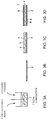
- FIGs. 3A to 3D are diagrams showing a process of producing an anti-wear sheet according to an embodiment.
- the ceramic powder 6 is added to the photo-curable resin 5 to prepare a resin composition 7 which includes the photo-curable resin 5 and the ceramic powder 6 and has fluidity.
- the photo-curable resin 5 and the ceramic powder 6 may be dispersed in a solvent to obtain the resin composition 7 in slurry form.
- the ceramic powder 6 may be added to the photo-curable resin 5 so that the ratio by weight of the ceramic powder 6 to the photo-curable resin 5 is from 1 to 6.
- the resin composition 7 prepared as in FIG. 3A is spread out to a uniform thickness on the release film 2 depicted in FIG. 3B , and thereby the resin layer 4 in FIG. 3C is obtained.
- the resin composition 7 contains a solvent
- the solvent may be volatilized from the resin composition 7 spread out onto the release film 2 to obtain the resin layer 4. Accordingly, it is possible to maintain a sheet shape even after moving the anti-wear sheet 1 in a finished state.
- the resin composition 7 may be formed into a sheet shape so that the resin layer 4 has a thickness of from 1 mm to 5mm.
- the light-shielding film 8 is attached onto the resin layer 4 as depicted in FIG. 3D .
- the resin layer 4 may include the glass fiber 10 embedded therein to serve as a shape-maintaining base material.
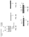
- FIGs. 4A to 4D are diagrams showing a process of producing an anti-wear sheet according to another embodiment.
- the ceramic powder 6 is added to the photo-curable resin 5 to prepare the resin composition 7 including the photo-curable resin 5 and the ceramic powder 6 and having fluidity.
- the glass fiber 10 depicted in FIG. 4C is put on the release film 2 depicted in FIG. 4B .
- the resin composition 7 prepared as in FIG. 4A is spread out to a uniform thickness to obtain the resin layer 4 in FIG. 4D .
- the glass fiber 10 is put on the release film 2 and then the resin composition 7 is applied to the release film 2 so that the glass fiber 10 is disposed on the side of the object 20 to be protected, and thereby it is possible to improve the shape-maintaining performance without sacrificing the anti-wear performance of the anti-wear sheet 1'.
- the resin composition 7 contains a solvent, the solvent may be volatilized from the resin composition 7 spread out onto the release film 2 to obtain the resin layer 4.
- the light-shielding film 8 is attached to the resin layer 4 as depicted in FIG. 4E .
- the production methods described with references to FIGs. 3A to 3D and FIGs. 4A to 4E may be performed by using either a roll-to-roll processing or a single-wafer processing.
- the release film 2 and the light-shielding film 8 are reeled out from respective rolls, and moved while undergoing the above described forming step and attaching step, and then the anti-wear sheet 1, 1' in a finished state is reeled again to create a roll.
- the anti-wear sheet 1 is processed by pieces, by applying the resin composition 7 to the release film 2 to form the resin layer 4, and then attaching the light-shielding film 8 to the resin layer 4.
- the light-shielding film 8 may be prepared in advance, the resin composition 7 may be applied onto the light-shielding film 8 to form the resin layer 4, and the release film 2 may be attached to the resin layer 4.
- the anti-wear sheet 1, 1' produced as described above may be stored in a light-shielding bag to prevent photo-curable resin from starting to cure.
- a light-shielding bag includes a material capable of absorbing or reflecting light having a wavelength that promotes polymerizing reaction of the photo-curable resin 5.
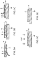
- a release-film removing step the release film 2 of the anti-wear sheet 1 depicted in FIG. 5A is peeled off. Then, in a release-film attaching step, as depicted in FIG. 5B , the anti-wear sheet 1 is placed on the object 20 to be protected so that a surface of the anti-wear sheet 1 exposed by removal of the release film 2 contacts a protection surface 21 of the object 20 to be protected. Subsequently, in a light-shielding-film removing step, as depicted in FIG. 5C , the light-shielding film 8 is removed from the release film attached to the protection surface 21 of the object 20 to be protected. Then, as depicted in FIG.
- the resin layer 4 exposed by removal of the light-shielding film 8 is irradiated with light and cured. It is sufficient if light to irradiate the resin layer 4 includes light of a wavelength that promotes polymerizing reaction of the photo-curable resin 5, and the light may be natural light or artificial light emitted by an optional light source. Accordingly, as depicted in FIG. 5E , an anti-wear material including the resin layer 4 is applied onto the protection surface 21 of the object 20 to be protected.
- the contained amount of the ceramic powder 6 has less influence on workability than in a method of forming an anti-wear layer by applying a resin composition in slurry form (coating) containing ceramic powder to an object to be protected, and thus it is possible to increase the contained amount of the ceramic powder 6 in the resin layer 4 of the anti-wear sheet 1 to improve anti-wear performance. Accordingly, it is possible to improve anti-wear performance and ensure good workability at the same time.
- the photo-curable resin 5 supports the ceramic powder 6 and forms the resin layer 4, and thereby the resin layer 4 can be cured basically by light irradiation alone, which makes it possible to improve workability.
- the photo-curable resin 5 can be replaced by thermosetting resin or thermoplastic resin, a device for heating the resin layer 4 would be required in that case, which makes application too extensive and difficult to be performed at a high altitude or in a narrow space. Moreover, uniform heating is difficult, and thus results may be uneven in a finished product.
- the photo-curable resin 5 is used, it is possible to cure the resin layer 4 uniformly by using natural light without involving an elaborate device for application, for instance, and thereby high workability can be achieved.
- the light-shielding film 8 disposed on a side of the resin layer 4, it is possible to suppress curing of the resin layer 4 while the resin layer 4 is being attached to the object 20 to be protected after the release film 2 is peeled off. It should be noted that the release film 2 may also have a light-shielding property. Moreover, with the release film 2 disposed on the other side of the resin layer 4, it is possible to prevent the resin layer 4 from adhering to another substance during storage.
- a Taber abrasion test is a test to abrade a specimen by continuous friction with two abrading wheels that roll on the specimen mounted to a rotary platform like a disk.
- a Taber abrasion test was performed in accordance with Japanese Industrial Standard (JIS) K7204 on two specimens: the anti-wear sheet 1 produced by the production method described in FIG. 2 and attached to the object 20 to be protected, which is an embodiment; and a specimen with mixture coating of photo-curable resin and ceramic powder applied to an object to be protected, which is a comparative example.
- JIS Japanese Industrial Standard
- photo-curable polyester resin was used as photo-curable resin
- alumina of a grain size #2000 was used as ceramic powder.
- photo-curable polyester resin and ceramic powder were mixed at a ratio of 100:150 to produce the coating.
- This coating was applied to a protection surface of an object to be protected to a thickness of 2mm, and then irradiated for 20 minutes with ultraviolet from a UV lamp (1000W) positioned at an irradiation distance of 200mm from the application surface, before conducting the following abrasion test.
- a UV lamp 1000W
- photo-curable polyester resin and ceramic powder were mixed at a ratio of 100:350 to produce the resin composition.
- the resin composition was spread out onto the release film to form a resin layer of 2mm thickness, and the light-shielding film was attached onto the resin layer to obtain the anti-wear sheet 1.
- This anti-wear sheet 1, from which the release film 2 is removed, was attached to the protection surface 21 of the object 20 to be protected, the light-shielding film 8 then peeled off, and then irradiated for 20 minutes with ultraviolet from a UV lamp (1000W) positioned at an irradiation distance of 200mm from the application surface, which is the same condition as the comparative example, before conducting the following abrasion test.
- a UV lamp 1000W
- a tester provided with abrading wheels CS-17 was used to apply a load to each specimen for a duration of 1000 cycles, using loads of 1000mg, and an amount of abrasion loss in a sheet by the abrading wheels was measured.
- the amount of abrasion loss from the object to be protected coated with the mixture coating of the comparative example was 80mg, whereby the amount of abrasion loss from the object to be protected with the anti-wear sheet 1 of the embodiment attached thereto was 132mg.
- the difference in the amount of abrasion loss between the comparative example and the embodiment may be due to the contained amount of ceramic powder.
- the anti-wear sheet 1 was produced and thus a large amount of ceramic powder could be contained, which may have been the reason why the amount of abrasion loss was reduced considerably. Accordingly, the anti-wear sheet 1 of the embodiment can achieve extremely high anti-wear performance and therefore is effective.
- the anti-wear sheet described in the embodiments of the present invention can be applied to various wear locations, especially to wear locations damaged by erosion, such as a wind turbine blade, a rotary blade of a rotary-blade airplane, a fixed wing of a fixed-wing airplane (main wings, tail, aileron, etc.), and an axial fan or a piping inner wall surface of various industrial plants.
Landscapes
- Engineering & Computer Science (AREA)
- Mechanical Engineering (AREA)
- General Engineering & Computer Science (AREA)
- Aviation & Aerospace Engineering (AREA)
- Textile Engineering (AREA)
- Laminated Bodies (AREA)
Abstract
Description
- The present disclosure relates to an anti-wear sheet for improving anti-wear performance of an object to be protected, a production method for the same, and an anti-wear-sheet application method.
- In general, an anti-wear material is often applied to a location of wear on equipment such as a wind turbine blade, an airplane blade, or a fan or an inner wall surface of piping of various industrial plants, for instance, to protect the equipment from wear.
- For instance, a wind turbine blade may be damaged by erosion from being repetitively hit by rain drops or dust. Especially, in recent years, blades are increased in size and damage is more serious at blade tips with an increased tip speed, which may lead to a rapid decrease in power-generation efficiency. Thus, a resin liner is applied to a location of wear on a blade to prevent wear. Furthermore, a sea-water pipe for cooling an industrial plant may be damaged by erosion from carrying seawater containing sand. Thus, a liner is applied to an inner wall surface of a pipe to prevent abrasion loss of the pipe.
- As one of the methods of producing an anti-wear material for such usages,
Patent Document 1 discloses a method of forming a resin layer on an object to be protected. In this method, mixture of resin particles and ceramic powder is disposed on an object to be protected, and the mixture is pressurized while being heated, and thereby a resin layer including ceramic powder is formed on the object to be protected. - Patent Document 1:
JPH3-65339A - However, the method described in
Patent Document 1 involves placing mixture of resin particles and ceramic powder on an object to be protected, as well as pressurizing and melting the mixture, and thus application would be difficult without well-prepared facilities. Thus, it may be difficult to adopt the method described inPatent Document 1 for on-site repair of an object to be protected that has been damaged by erosion. - Meanwhile, besides the method described in
Patent Document 1, an anti-wear layer can be formed on an object to be protected by applying a resin composition in slurry form (coating) containing ceramic powder onto the object. - In this method, however, increasing the amount of additive ceramic powder to achieve higher anti-wear performance may lead to a decrease in fluidity of the resin composition, which makes the application work difficult. Accordingly, it may be difficult to improve anti-wear performance and ensure good workability at the same time.
- An object of at least one embodiment of the present invention is to provide an anti-wear sheet which can be applied without extensive facilities and which can achieve both improved anti-wear performance and high workability, as well as a method of producing the same and a method of applying an anti-wear sheet.
- An anti-wear sheet for improving anti-wear performance of an object to be protected, according to at least one embodiment of the present invention, comprises: a release film; a resin layer disposed on the release film and including photo-curable resin and hard particles supported by the photo-curable resin; and a light-shielding film disposed on an opposite side of the resin layer from the release film.
- With the above anti-wear sheet, it is possible to increase the contained amount of the hard particles without strict limitation imposed for the sake of workability. Specifically, in the above embodiments, the contained amount of the hard particles has less influence on workability than in a method of forming an anti-wear layer by applying a resin composition in slurry form (coating) containing ceramic powder to an object to be protected, and thus it is possible to increase the contained amount of the hard particles in the resin layer of the anti-wear sheet to improve anti-wear performance. Accordingly, it is possible to improve anti-wear performance and ensure good workability at the same time.
- Further, the photo-curable resin supports the hard particles and forms the resin layer, and thereby the resin layer can be cured basically by light irradiation alone, which makes it possible to improve workability. For instance, while the photo-curable resin can be replaced by thermosetting resin or thermoplastic resin, a device for heating the resin layer would be required in that case, which makes application too extensive and difficult to be performed at a high altitude or in a narrow space. Moreover, uniform heating is difficult, and thus results may be uneven in a finished product. On the other hand, if the photo-curable resin is used, it is possible to cure the resin layer uniformly by using natural light without involving an elaborate device for application, for instance, and thereby high workability can be achieved. Further, with the light-shielding film disposed on a side of the resin layer, it is possible to suppress curing of the resin layer while the resin layer is being attached to the object to be protected after the release film is peeled off. It should be noted that the release film may also have a light-shielding property. Moreover, with the release film disposed on the other side of the resin layer, it is possible to prevent the resin layer from adhering to another substance during storage.
- In some embodiments, the anti-wear sheet further comprises a shape-maintaining base material embedded in the resin layer.
- Accordingly, even if the anti-wear sheet has large dimensions or area, the shape-maintaining base material maintains the shape of the sheet to some extent, and thereby transportation and application of the anti-wear sheet to an object to be protected are facilitated.
- In some embodiments, a ratio by weight of the hard particles to the photo-curable resin is from 1 to 6.
- Accordingly, with the ratio by weight of the hard particles to the photo-curable resin being one or more, it is possible to obtain an anti-wear sheet with a small amount of abrasion loss and high anti-wear performance. Also, with the ratio by weight of the hard particles to the photo-curable resin being six or less, it is possible to prevent generation of a poorly-cured section.
- In some embodiments, the resin layer has a thickness of from 1mm to 5mm.
- With the resin layer having a thickness of 1mm or more, a layer can be readily formed during production of the anti-wear sheet, and sufficient anti-wear performance can be readily ensured for the resin layer. Also, with the resin layer having a thickness of 5mm or less, sufficient light permeability can be achieved for the resin layer, and the resin layer can be light-cured securely during application of the anti-wear sheet.
- In an embodiment, the photo-curable resin comprises vinyl ester resin.
- In another embodiment, the hard particles comprises ceramic powder. Further, the hard particles may comprise ceramic powder containing alumina.
- A method of producing an anti-wear sheet for improving anti-wear performance of an object to be protected, according to at least one embodiment of the present invention, comprises: a preparing step of adding hard particles to photo-curable resin to prepare a resin composition which includes the photo-curable resin and the hard particles and which has fluidity; a forming step of forming the resin composition into a sheet shape on one of a release film or a light-shielding film to obtain a resin layer; and an attaching step of attaching the other one of the release film or the light-shielding film onto the resin layer.
- With the above anti-wear sheet obtained by the above method of producing an anti-wear sheet, it is possible to increase the contained amount of the hard particles without strict limitation imposed for the sake of workability. Specifically, in the above embodiments, the contained amount of the hard particles has less influence on workability than in a method of forming an anti-wear layer by applying a resin composition in slurry form
- (coating) containing ceramic powder to an object to be protected, and thus it is possible to increase the contained amount of the hard particles in the resin layer of the anti-wear sheet to improve anti-wear performance. Accordingly, it is possible to improve anti-wear performance and ensure good workability at the same time.
- Further, since the photo-curable resin supports the hard particles and forms the resin layer, and the resin layer can be cured basically by light irradiation alone, which makes it possible to improve workability. Further, with the light-shielding film disposed on a side of the resin layer, it is possible to suppress curing of the resin layer while the resin layer is being attached to the object to be protected after the release film is peeled off. It should be noted that the release film may also have a light-shielding property. Moreover, with the release film disposed on the other side of the resin layer, it is possible to prevent the resin layer from adhering to another substance during storage.
- In some embodiments, the preparing step comprises dispersing the photo-curable resin and the hard particles in a solvent to prepare the resin composition having fluidity, and the solvent is volatilized after the forming step.
- Accordingly, it is possible to include a sufficient amount of hard particles, and to produce an anti-wear sheet with a high anti-wear property.
- In some embodiments, the forming step comprises embedding a shape-maintaining base material in the resin layer.
- Accordingly, even an anti-wear sheet with a large length or diameter has a certain shape-maintaining function, and thereby it is possible to attach the anti-wear sheet readily to an object to be protected.
- In some embodiments, the preparing step comprises adding the hard particles to the photo-curable resin so that a ratio by weight of the hard particles to the photo-curable resin is from 1 to 6.
- Accordingly, with the ratio by weight of the hard particles to the photo-curable resin being one or more, it is possible to obtain an anti-wear sheet with a small amount of abrasion loss and high anti-wear performance. Also, with the ratio by weight of the hard particles to the photo-curable resin being 6 or less, it is possible to prevent generation of a poorly-cured section.
- In some embodiments, the forming step comprises forming the resin composition into a sheet shape so that the resin layer has a thickness of from 1mm to 5mm.
- With the resin layer having a thickness of 1mm or more, a layer can be readily formed during production of the anti-wear sheet, and sufficient anti-wear performance can be readily ensured for the resin layer. Also, with the resin layer having a thickness of 5mm or less, sufficient light permeability can be achieved for the resin layer, and the resin layer can be light-cured securely during application of the anti-wear sheet.
- A method of applying an anti-wear sheet for improving anti-wear performance of an object to be protected to the object, the anti-wear sheet comprising a release film, a resin layer disposed on the release film and including photo-curable resin and hard particles supported by the photo-curable resin, and a light-shielding film disposed on an opposite side of the resin layer from the release film, according to at least one embodiment of the present invention, comprises: a release-film removing step of removing the release film from the anti-wear sheet; a release-film attaching step of attaching the release film to a protection surface of the object to be protected; a light-shielding-film removing step of removing the light-shielding film from the release-film attached to the object to be protected; and a curing step of curing the resin layer by irradiating the resin layer exposed by removal of the light-shielding film with light.
- According to the above method of applying an anti-wear sheet, it is possible to increase the contained amount of the hard particles in a resin layer of an anti-wear sheet without strict limitation imposed for the sake of workability. Specifically, in the above embodiments, the contained amount of the hard particles has less influence on workability than in a method of forming an anti-wear layer by applying a resin composition in slurry form (coating) containing ceramic powder to an object to be protected, and thus it is possible to increase the contained amount of the hard particles in the resin layer of the anti-wear sheet to improve anti-wear performance. Accordingly, it is possible to improve anti-wear performance and ensure good workability at the same time.
- Further, since the photo-curable resin supports the hard particles and forms the resin layer, the resin layer can be cured basically by light irradiation alone, which makes it possible to improve workability. Further, with the light-shielding film disposed on a side of the resin layer, it is possible to suppress curing of the resin layer while the resin layer is being attached to the object to be protected after the release film is peeled off. It should be noted that the release film may also have a light-shielding property. Moreover, with the release film disposed on the other side of the resin layer, it is possible to prevent the resin layer from adhering to another substance during storage.
- According to at least one embodiment of the present invention, it is possible to improve anti-wear performance of a resin layer and ensure good workability of an anti-wear sheet at the same time. Further, since the photo-curable resin supports the hard particles and forms the resin layer, the resin layer can be cured basically by light irradiation alone, which makes it possible to improve workability.
-
-
FIG. 1 is a perspective view of an anti-wear sheet according to an embodiment. -
FIG. 2 is a perspective view of an anti-wear sheet according to another embodiment. -
FIGs. 3A to 3D are diagrams showing a process of producing an anti-wear sheet according to an embodiment. -
FIGs. 4A to 4E are diagrams showing a process of producing an anti-wear sheet according to another embodiment. -
FIGs. 5A to 5E are diagrams showing a process of applying an anti-wear sheet according to an embodiment. - Embodiments of the present invention will now be described with reference to the accompanying drawings. It is intended, however, that unless particularly specified, dimensions, materials, shapes, relative positions and the like of components described in the embodiments shall be interpreted as illustrative only and not intended to limit the scope of the present invention.
- An anti-wear sheet according to an embodiment of the present invention is used to improve anti-wear performance of an object to be protected.
- An anti-wear sheet according to embodiments of the present invention will now be described, and then a method of producing the anti-wear sheet and a method of applying the anti-wear sheet will be described in this order.
-
FIG. 1 is a perspective view of an anti-wear sheet according to an embodiment. As illustrated in the drawing, in an embodiment, theanti-wear sheet 1 includes arelease film 2, aresin layer 4, and a light-shieldingfilm 8. - The
release film 2 is disposed on a side of theresin layer 4, and is readily separatable from theresin layer 4. For instance, therelease film 2 may be a film coated with silicone. Therelease film 2 may have a light-shielding property. Specifically, therelease film 2 includes a material capable of absorbing or reflecting light having a wavelength that promotes polymerizing reaction of photo-curable resin 5 described below. - The
resin layer 4 includes the photo-curable resin 5 andceramic powder 6 supported by the photo-curable resin 5. - The photo-
curable resin 5 is in a non-cured or half-cured state, and has an adhesive property (tack) strong enough to adhere theresin layer 4 to an object to be protected. The photo-curable resin 5 is not particularly limited as long as the photo-curable resin 5 is such a resin that polymerizing reaction of the resin develops by being irradiated with light of a specific wavelength, and may be epoxy resin, vinyl ester resin, or the like. - The
ceramic powder 6 may contain alumina. Instead of theceramic powder 6, optional hard particles (e.g. metal powder) harder than the photo-curable resin 5 may be used. - The
resin layer 4 may have a thickness of from 1 mm to 5mm. - With the
resin layer 4 having a thickness of 1 mm or more, a layer can be readily formed during production of theanti-wear sheet 1, and sufficient anti-wear performance can be readily ensured for theresin layer 4. Also, with theresin layer 4 having a thickness of 5mm or less, sufficient light permeability can be achieved for theresin layer 4, and theresin layer 4 can be light-cured securely during application of theanti-wear sheet 1. - Further, the ratio by weight of the
ceramic powder 6 to the photo-curable resin 5 may be from 1 to 6. - Accordingly, with the ratio by weight of the
ceramic powder 6 to the photo-curable resin 5 being 1 or more, it is possible to form theanti-wear sheet 1 with a small amount of abrasion loss and high anti-wear performance. Also, with the ratio by weight of theceramic powder 6 to the photo-curable resin 5 being 6 or less, it is possible to prevent generation of a poorly-cured section. - The light-shielding
film 8 is disposed on the opposite side of theresin layer 4 from therelease film 2. Further, therelease film 8 has a light-shielding property. The light-shieldingfilm 8 includes a material capable of absorbing or reflecting light having a wavelength that promotes polymerizing reaction of the photo-curable resin 5. Further, the light-shieldingfilm 8 may be readily separatable from theresin layer 4. -
FIG. 2 is a perspective view of an anti-wear sheet according to another embodiment. InFIG. 2 , the same parts as those inFIG. 1 are associated with the same reference numerals and not described in detail. - As illustrated in the drawing, in an embodiment, the anti-wear sheet 1' includes the
release film 2, theresin layer 4 with aglass fiber 10, and the light-shieldingfilm 8. - The
glass fiber 10 is embedded in theresin layer 4 to serve as a shape-maintaining base material. A shape-maintaining base material to be embedded in theresin layer 4 is not particularly limited as long as the shape-maintaining base material can help maintain the shape of theresin layer 4 in a non-cured or half-cured state, and may be a material other than theglass fiber 10. - The
glass fiber 10 may include fibers laid in one direction, or woven fibers. - Further, the
glass fiber 10 may be disposed on a side adjacent to therelease film 2 within theresin layer 4. Theglass fiber 10 mainly functions as a shape-maintaining base material, and has little or no contribution to anti-wear performance. Thus, with theglass fiber 10 being disposed on the side of an object to be protected (i.e., on the side adjacent to the release film 2), it is possible to improve the shape-maintaining performance without sacrificing the anti-wear performance of the anti-wear sheet 1'. - Accordingly, even if the anti-wear sheet 1' has large dimensions or area, the shape-maintaining base material (glass fiber 10) maintains the shape of the anti-wear sheet 1' to some extent, and thereby transportation of the anti-wear sheet 1' and application of the anti-wear sheet 1' to an
object 20 to be protected are facilitated. - A method of producing an anti-wear sheet according to an embodiment will now be described in detail.
FIGs. 3A to 3D are diagrams showing a process of producing an anti-wear sheet according to an embodiment. - In an embodiment, to start with, in a preparing step depicted in
FIG. 3A , theceramic powder 6 is added to the photo-curable resin 5 to prepare aresin composition 7 which includes the photo-curable resin 5 and theceramic powder 6 and has fluidity. In this step, the photo-curable resin 5 and theceramic powder 6 may be dispersed in a solvent to obtain theresin composition 7 in slurry form. Further, in the preparing step, theceramic powder 6 may be added to the photo-curable resin 5 so that the ratio by weight of theceramic powder 6 to the photo-curable resin 5 is from 1 to 6. - Next, in a forming step, the
resin composition 7 prepared as inFIG. 3A is spread out to a uniform thickness on therelease film 2 depicted inFIG. 3B , and thereby theresin layer 4 inFIG. 3C is obtained. If theresin composition 7 contains a solvent, the solvent may be volatilized from theresin composition 7 spread out onto therelease film 2 to obtain theresin layer 4. Accordingly, it is possible to maintain a sheet shape even after moving theanti-wear sheet 1 in a finished state. In the forming step, theresin composition 7 may be formed into a sheet shape so that theresin layer 4 has a thickness of from 1 mm to 5mm. After the solvent is volatilized, in an attaching step, the light-shieldingfilm 8 is attached onto theresin layer 4 as depicted inFIG. 3D . - In another embodiment, as illustrated in
FIG. 4 , theresin layer 4 may include theglass fiber 10 embedded therein to serve as a shape-maintaining base material.FIGs. 4A to 4D are diagrams showing a process of producing an anti-wear sheet according to another embodiment. - In a preparing step depicted in
FIG. 4A , theceramic powder 6 is added to the photo-curable resin 5 to prepare theresin composition 7 including the photo-curable resin 5 and theceramic powder 6 and having fluidity. - Next, in a forming step, the
glass fiber 10 depicted inFIG. 4C is put on therelease film 2 depicted inFIG. 4B . Next, theresin composition 7 prepared as inFIG. 4A is spread out to a uniform thickness to obtain theresin layer 4 inFIG. 4D . Accordingly, theglass fiber 10 is put on therelease film 2 and then theresin composition 7 is applied to therelease film 2 so that theglass fiber 10 is disposed on the side of theobject 20 to be protected, and thereby it is possible to improve the shape-maintaining performance without sacrificing the anti-wear performance of the anti-wear sheet 1'. If theresin composition 7 contains a solvent, the solvent may be volatilized from theresin composition 7 spread out onto therelease film 2 to obtain theresin layer 4. Then, in an attaching step, the light-shieldingfilm 8 is attached to theresin layer 4 as depicted inFIG. 4E . - The production methods described with references to
FIGs. 3A to 3D andFIGs. 4A to 4E may be performed by using either a roll-to-roll processing or a single-wafer processing. - In the roll-to-roll processing, the
release film 2 and the light-shieldingfilm 8 are reeled out from respective rolls, and moved while undergoing the above described forming step and attaching step, and then theanti-wear sheet 1, 1' in a finished state is reeled again to create a roll. In contrast, in the single-wafer processing, theanti-wear sheet 1 is processed by pieces, by applying theresin composition 7 to therelease film 2 to form theresin layer 4, and then attaching the light-shieldingfilm 8 to theresin layer 4. In the single-wafer processing, the light-shieldingfilm 8 may be prepared in advance, theresin composition 7 may be applied onto the light-shieldingfilm 8 to form theresin layer 4, and therelease film 2 may be attached to theresin layer 4. - With regard to storage, the
anti-wear sheet 1, 1' produced as described above may be stored in a light-shielding bag to prevent photo-curable resin from starting to cure. Such a light-shielding bag includes a material capable of absorbing or reflecting light having a wavelength that promotes polymerizing reaction of the photo-curable resin 5. - Next, with reference to
FIG. 5 , a method of applying theanti-wear sheet 1 depicted inFIG. 1 or theanti-wear sheet 1 produced by the production method described with reference toFIG. 3 will now be described. - To start with, in a release-film removing step, the
release film 2 of theanti-wear sheet 1 depicted inFIG. 5A is peeled off. Then, in a release-film attaching step, as depicted inFIG. 5B , theanti-wear sheet 1 is placed on theobject 20 to be protected so that a surface of theanti-wear sheet 1 exposed by removal of therelease film 2 contacts aprotection surface 21 of theobject 20 to be protected. Subsequently, in a light-shielding-film removing step, as depicted inFIG. 5C , the light-shieldingfilm 8 is removed from the release film attached to theprotection surface 21 of theobject 20 to be protected. Then, as depicted inFIG. 5D , in a curing step, theresin layer 4 exposed by removal of the light-shieldingfilm 8 is irradiated with light and cured. It is sufficient if light to irradiate theresin layer 4 includes light of a wavelength that promotes polymerizing reaction of the photo-curable resin 5, and the light may be natural light or artificial light emitted by an optional light source. Accordingly, as depicted inFIG. 5E , an anti-wear material including theresin layer 4 is applied onto theprotection surface 21 of theobject 20 to be protected. - As described above, according to the above embodiments, it is possible to increase the contained amount of the
ceramic powder 6 without strict limitation imposed for the sake of workability. Specifically, in the above embodiments, the contained amount of theceramic powder 6 has less influence on workability than in a method of forming an anti-wear layer by applying a resin composition in slurry form (coating) containing ceramic powder to an object to be protected, and thus it is possible to increase the contained amount of theceramic powder 6 in theresin layer 4 of theanti-wear sheet 1 to improve anti-wear performance. Accordingly, it is possible to improve anti-wear performance and ensure good workability at the same time. - Further, the photo-
curable resin 5 supports theceramic powder 6 and forms theresin layer 4, and thereby theresin layer 4 can be cured basically by light irradiation alone, which makes it possible to improve workability. For instance, while the photo-curable resin 5 can be replaced by thermosetting resin or thermoplastic resin, a device for heating theresin layer 4 would be required in that case, which makes application too extensive and difficult to be performed at a high altitude or in a narrow space. Moreover, uniform heating is difficult, and thus results may be uneven in a finished product. On the other hand, if the photo-curable resin 5 is used, it is possible to cure theresin layer 4 uniformly by using natural light without involving an elaborate device for application, for instance, and thereby high workability can be achieved. Further, with the light-shieldingfilm 8 disposed on a side of theresin layer 4, it is possible to suppress curing of theresin layer 4 while theresin layer 4 is being attached to theobject 20 to be protected after therelease film 2 is peeled off. It should be noted that therelease film 2 may also have a light-shielding property. Moreover, with therelease film 2 disposed on the other side of theresin layer 4, it is possible to prevent theresin layer 4 from adhering to another substance during storage. - Next, results of a Taber abrasion test for evaluating anti-wear performance of the
anti-wear sheet 1 will now be described. A Taber abrasion test is a test to abrade a specimen by continuous friction with two abrading wheels that roll on the specimen mounted to a rotary platform like a disk. In the test, a Taber abrasion test was performed in accordance with Japanese Industrial Standard (JIS) K7204 on two specimens: theanti-wear sheet 1 produced by the production method described inFIG. 2 and attached to theobject 20 to be protected, which is an embodiment; and a specimen with mixture coating of photo-curable resin and ceramic powder applied to an object to be protected, which is a comparative example. - In this test, photo-curable polyester resin was used as photo-curable resin, and alumina of a grain size #2000 was used as ceramic powder.
- In the comparative example, photo-curable polyester resin and ceramic powder were mixed at a ratio of 100:150 to produce the coating. This coating was applied to a protection surface of an object to be protected to a thickness of 2mm, and then irradiated for 20 minutes with ultraviolet from a UV lamp (1000W) positioned at an irradiation distance of 200mm from the application surface, before conducting the following abrasion test.
- On the other hand, for the embodiment, photo-curable polyester resin and ceramic powder were mixed at a ratio of 100:350 to produce the resin composition. The resin composition was spread out onto the release film to form a resin layer of 2mm thickness, and the light-shielding film was attached onto the resin layer to obtain the
anti-wear sheet 1. Thisanti-wear sheet 1, from which therelease film 2 is removed, was attached to theprotection surface 21 of theobject 20 to be protected, the light-shieldingfilm 8 then peeled off, and then irradiated for 20 minutes with ultraviolet from a UV lamp (1000W) positioned at an irradiation distance of 200mm from the application surface, which is the same condition as the comparative example, before conducting the following abrasion test. - In the abrasion test, a tester provided with abrading wheels CS-17 was used to apply a load to each specimen for a duration of 1000 cycles, using loads of 1000mg, and an amount of abrasion loss in a sheet by the abrading wheels was measured. As a result, the amount of abrasion loss from the object to be protected coated with the mixture coating of the comparative example was 80mg, whereby the amount of abrasion loss from the object to be protected with the
anti-wear sheet 1 of the embodiment attached thereto was 132mg. The difference in the amount of abrasion loss between the comparative example and the embodiment may be due to the contained amount of ceramic powder. That is, in the embodiment, theanti-wear sheet 1 was produced and thus a large amount of ceramic powder could be contained, which may have been the reason why the amount of abrasion loss was reduced considerably. Accordingly, theanti-wear sheet 1 of the embodiment can achieve extremely high anti-wear performance and therefore is effective. - Embodiments of the present invention were described in detail above, but the present invention is not limited thereto, and various amendments and modifications may be implemented within a scope that does not depart from the present invention.
- The anti-wear sheet described in the embodiments of the present invention can be applied to various wear locations, especially to wear locations damaged by erosion, such as a wind turbine blade, a rotary blade of a rotary-blade airplane, a fixed wing of a fixed-wing airplane (main wings, tail, aileron, etc.), and an axial fan or a piping inner wall surface of various industrial plants.
-
- I
- Anti-wear sheet
- 2
- Release film
- 4
- Resin layer
- 5
- Photo-curable resin
- 6
- Ceramic powder
- 7
- Resin composition
- 8
- Light-shielding film
- 10
- Glass fiber
- 20
- Object to be protected
- 21
- Protection surface
Claims (12)
- An anti-wear sheet for improving anti-wear performance of an object to be protected, comprising:a release film;a resin layer disposed on the release film and including photo-curable resin and hard particles supported by the photo-curable resin; anda light-shielding film disposed on an opposite side of the resin layer from the release film.
- The anti-wear sheet according to claim 1, further comprising a shape-maintaining base material embedded in the resin layer.
- The anti-wear sheet according to claim 1 or 2, wherein a ratio by weight of the hard particles to the photo-curable resin is from 1 to 6.
- The anti-wear sheet according to any one of claims 1 to 3, wherein the resin layer has a thickness of from 1mm to 5mm.
- The anti-wear sheet according to any one of claims 1 to 4, wherein the photo-curable resin comprises vinyl ester resin.
- The anti-wear sheet according to any one of claims 1 to 5, wherein the hard particles comprises ceramic powder.
- A method of producing an anti-wear sheet for improving anti-wear performance of an object to be protected, the method comprising:a preparing step of adding hard particles to photo-curable resin to prepare a resin composition which includes the photo-curable resin and the hard particles and which has fluidity;a forming step of forming the resin composition into a sheet shape on one of a release film or a light-shielding film to obtain a resin layer; andan attaching step of attaching the other one of the release film or the light-shielding film onto the resin layer.
- The method of producing an anti-wear sheet according to claim 7,
wherein the preparing step comprises dispersing the photo-curable resin and the hard particles in a solvent to prepare the resin composition having fluidity, and
wherein the solvent is volatilized after the forming step. - The method of producing an anti-wear sheet according to claim 7 or 8,
wherein the forming step comprises embedding a shape-maintaining base material in the resin layer. - The method of producing an anti-wear sheet according to any one of claims 7 to 9,
wherein the preparing step comprises adding the hard particles to the photo-curable resin so that a ratio by weight of the hard particles to the photo-curable resin is from 1 to 6. - The method of producing an anti-wear sheet according to any one of claims 7 to 10,
wherein the forming step comprises forming the resin composition into a sheet shape so that the resin layer has a thickness of from 1mm to 5mm. - A method of applying an anti-wear sheet for improving anti-wear performance of an object to be protected to the object, the anti-wear sheet comprising a release film, a resin layer disposed on the release film and including photo-curable resin and hard particles supported by the photo-curable resin, and a light-shielding film disposed on an opposite side of the resin layer from the release film, and the method comprising:a release-film removing step of removing the release film from the anti-wear sheet;a release-film attaching step of attaching the release film to a protection surface of the object to be protected;a light-shielding-film removing step of removing the light-shielding film from the release-film attached to the object to be protected; anda curing step of curing the resin layer by irradiating the resin layer exposed by removal of the light-shielding film with light.
Applications Claiming Priority (2)
| Application Number | Priority Date | Filing Date | Title |
|---|---|---|---|
| JP2013256902A JP6317098B2 (en) | 2013-12-12 | 2013-12-12 | Abrasion-resistant sheet, method for producing the same, and construction method for abrasion-resistant sheet |
| PCT/JP2014/082811 WO2015087962A1 (en) | 2013-12-12 | 2014-12-11 | Anti-friction sheet, production method for same, and anti-friction-sheet construction method |
Publications (3)
| Publication Number | Publication Date |
|---|---|
| EP3067202A1 true EP3067202A1 (en) | 2016-09-14 |
| EP3067202A4 EP3067202A4 (en) | 2016-11-30 |
| EP3067202B1 EP3067202B1 (en) | 2017-11-15 |
Family
ID=53371261
Family Applications (1)
| Application Number | Title | Priority Date | Filing Date |
|---|---|---|---|
| EP14870040.4A Not-in-force EP3067202B1 (en) | 2013-12-12 | 2014-12-11 | Anti-wear sheet, production method for the same, and anti-wear-sheet application method |
Country Status (5)
| Country | Link |
|---|---|
| US (1) | US10213996B2 (en) |
| EP (1) | EP3067202B1 (en) |
| JP (1) | JP6317098B2 (en) |
| CN (1) | CN105848893B (en) |
| WO (1) | WO2015087962A1 (en) |
Cited By (1)
| Publication number | Priority date | Publication date | Assignee | Title |
|---|---|---|---|---|
| EP3782812A1 (en) * | 2019-08-20 | 2021-02-24 | Roller Bearing Company of America, Inc. | Permanent, self-adhering, self-lubricating, anti-wear composite system |
Families Citing this family (2)
| Publication number | Priority date | Publication date | Assignee | Title |
|---|---|---|---|---|
| US10760600B2 (en) * | 2017-10-27 | 2020-09-01 | General Electric Company | Method of applying riblets to an aerodynamic surface |
| JP6588119B2 (en) * | 2018-03-29 | 2019-10-09 | 三菱重工業株式会社 | Wind turbine blade repair, reinforcement, or attachment method |
Family Cites Families (9)
| Publication number | Priority date | Publication date | Assignee | Title |
|---|---|---|---|---|
| JP2841081B2 (en) * | 1989-08-03 | 1998-12-24 | 昭和飛行機工業株式会社 | Manufacturing method of wear resistant material |
| JP3043005U (en) * | 1997-04-30 | 1997-11-11 | エスジーシー下水道センター株式会社 | Partial repair material on the inner surface of the pipe |
| JPH1161361A (en) | 1997-08-13 | 1999-03-05 | Mitsubishi Heavy Ind Ltd | Heat resistant and wear resistant material |
| KR20020062974A (en) * | 1999-12-28 | 2002-07-31 | 가부시키가이샤 닛폰 쇼쿠바이 | Multilayer material |
| JP2002018991A (en) * | 2000-07-04 | 2002-01-22 | Showa Highpolymer Co Ltd | Curable prepreg, production method and curing method |
| JP2002265635A (en) * | 2001-03-14 | 2002-09-18 | Nippon Shokubai Co Ltd | Sheet-formed reinforcing material |
| JP4236416B2 (en) * | 2001-04-02 | 2009-03-11 | ジャパンコンポジット株式会社 | Sheet-like reinforcing material and method for manufacturing the same |
| JP2003071994A (en) | 2001-09-06 | 2003-03-12 | Hoshino Sansho:Kk | Functional sheet |
| JP2006104394A (en) * | 2004-10-08 | 2006-04-20 | Asahi Kasei Chemicals Corp | Photo-curable prepreg sheet with protective film |
-
2013
- 2013-12-12 JP JP2013256902A patent/JP6317098B2/en active Active
-
2014
- 2014-12-11 US US15/103,222 patent/US10213996B2/en not_active Expired - Fee Related
- 2014-12-11 CN CN201480067000.1A patent/CN105848893B/en not_active Expired - Fee Related
- 2014-12-11 EP EP14870040.4A patent/EP3067202B1/en not_active Not-in-force
- 2014-12-11 WO PCT/JP2014/082811 patent/WO2015087962A1/en not_active Ceased
Non-Patent Citations (3)
| Title |
|---|
| No further relevant documents disclosed * |
| None * |
| See also references of WO2015087962A1 * |
Cited By (3)
| Publication number | Priority date | Publication date | Assignee | Title |
|---|---|---|---|---|
| EP3782812A1 (en) * | 2019-08-20 | 2021-02-24 | Roller Bearing Company of America, Inc. | Permanent, self-adhering, self-lubricating, anti-wear composite system |
| US11299654B2 (en) | 2019-08-20 | 2022-04-12 | Roller Bearing Company Of America, Inc. | Permanent, self-adhering, self-lubricating, anti-wear composite system |
| US12215260B2 (en) | 2019-08-20 | 2025-02-04 | Roller Bearing Company Of America, Inc. | Permanent, self-adhering, self-lubricating, anti-wear composite system |
Also Published As
| Publication number | Publication date |
|---|---|
| US20160354999A1 (en) | 2016-12-08 |
| US10213996B2 (en) | 2019-02-26 |
| JP6317098B2 (en) | 2018-04-25 |
| EP3067202A4 (en) | 2016-11-30 |
| CN105848893A (en) | 2016-08-10 |
| CN105848893B (en) | 2018-04-03 |
| JP2015112808A (en) | 2015-06-22 |
| EP3067202B1 (en) | 2017-11-15 |
| WO2015087962A1 (en) | 2015-06-18 |
Similar Documents
| Publication | Publication Date | Title |
|---|---|---|
| Çoban et al. | Laser surface treatment of CFRP composites for a better adhesive bonding owing to the mechanical interlocking mechanism | |
| EP3067202B1 (en) | Anti-wear sheet, production method for the same, and anti-wear-sheet application method | |
| JP5633078B2 (en) | Fabrication of fragile specimen flakes by dry polishing | |
| RU2014129622A (en) | METHOD FOR PRODUCING HOMOGENEOUS MATTED COATINGS USING RADIATION CURING | |
| RU2016103279A (en) | METHOD FOR PREPARING SUBSTRATES FOR THERMAL SPRAYING OF METAL COATING | |
| CN109641809A (en) | Thermal barrier coating remediation composition and its application method | |
| CN104853904A (en) | Method for processing a fiber-plastic composite of a rotor blade, semifinished product in the form of a built-up composite, and uv lamp for curing a uv-curable matrix material | |
| MXPA04001038A (en) | Process for repairing coated substrate surfaces. | |
| WO2015151611A1 (en) | Layered-shaped-article manufacturing device, manufacturing method, and liquid feedstock | |
| CN107814969A (en) | A kind of translucent minute surface colorful film and preparation method thereof | |
| CN104327593A (en) | UV-curable strippable ink as well as production method and construction method of UV-curable strippable ink | |
| WO2016062768A3 (en) | Method of coating substrate | |
| US20160151944A1 (en) | Methods, systems, and devices for radio-frequency assisted removal of sealant | |
| CN103396731A (en) | Anti-scratching writing coating | |
| PL236872B1 (en) | Method for coating metallic surface intended for receiving elastomer and the related set and tool | |
| Gao et al. | A study on radiation effect of< 200 keV protons on M40J/epoxy composites | |
| Dong et al. | Influence of hydrothermal aging process on components and properties of waterborne fire-resistive coatings | |
| JP2015112808A5 (en) | ||
| Jing et al. | Improving the anti-thermal-shock properties of Sc2O3-Y2O3-ZrO2-CaF2-PHB abradable coatings by fabricating the textures on ceramic matrix composites: experiment verification and numerical analysis | |
| Lin et al. | Mold cleaning with polydimethylsiloxane for nanoimprint lithography | |
| CN106318191A (en) | UV LED low-energy curing decorative material coating and preparation method thereof | |
| CN103360779B (en) | A kind of manufacture method of compound resin sill 10KV switch box | |
| CN105303967A (en) | Method for bonding light-permeable base material | |
| Yang et al. | Atmospheric Pressure Argon Plasma Jet Enhances the Surface Repair Effect of Wind Turbine Blades | |
| CN102721601A (en) | Method for detecting damage of resin matrix composites due to ultraviolet A (UVA) ray irradiation |
Legal Events
| Date | Code | Title | Description |
|---|---|---|---|
| PUAI | Public reference made under article 153(3) epc to a published international application that has entered the european phase |
Free format text: ORIGINAL CODE: 0009012 |
|
| 17P | Request for examination filed |
Effective date: 20160606 |
|
| AK | Designated contracting states |
Kind code of ref document: A1 Designated state(s): AL AT BE BG CH CY CZ DE DK EE ES FI FR GB GR HR HU IE IS IT LI LT LU LV MC MK MT NL NO PL PT RO RS SE SI SK SM TR |
|
| AX | Request for extension of the european patent |
Extension state: BA ME |
|
| A4 | Supplementary search report drawn up and despatched |
Effective date: 20161102 |
|
| RIC1 | Information provided on ipc code assigned before grant |
Ipc: B32B 7/06 20060101ALI20161026BHEP Ipc: B32B 27/20 20060101AFI20161026BHEP Ipc: B32B 5/02 20060101ALI20161026BHEP Ipc: C09J 7/02 20060101ALI20161026BHEP Ipc: C08J 5/24 20060101ALI20161026BHEP |
|
| DAX | Request for extension of the european patent (deleted) | ||
| GRAP | Despatch of communication of intention to grant a patent |
Free format text: ORIGINAL CODE: EPIDOSNIGR1 |
|
| INTG | Intention to grant announced |
Effective date: 20170428 |
|
| GRAS | Grant fee paid |
Free format text: ORIGINAL CODE: EPIDOSNIGR3 |
|
| GRAA | (expected) grant |
Free format text: ORIGINAL CODE: 0009210 |
|
| AK | Designated contracting states |
Kind code of ref document: B1 Designated state(s): AL AT BE BG CH CY CZ DE DK EE ES FI FR GB GR HR HU IE IS IT LI LT LU LV MC MK MT NL NO PL PT RO RS SE SI SK SM TR |
|
| REG | Reference to a national code |
Ref country code: CH Ref legal event code: EP Ref country code: GB Ref legal event code: FG4D Ref country code: AT Ref legal event code: REF Ref document number: 945855 Country of ref document: AT Kind code of ref document: T Effective date: 20171115 |
|
| REG | Reference to a national code |
Ref country code: IE Ref legal event code: FG4D |
|
| REG | Reference to a national code |
Ref country code: DE Ref legal event code: R096 Ref document number: 602014017428 Country of ref document: DE Ref country code: FR Ref legal event code: PLFP Year of fee payment: 4 |
|
| REG | Reference to a national code |
Ref country code: NL Ref legal event code: MP Effective date: 20171115 |
|
| REG | Reference to a national code |
Ref country code: LT Ref legal event code: MG4D |
|
| REG | Reference to a national code |
Ref country code: AT Ref legal event code: MK05 Ref document number: 945855 Country of ref document: AT Kind code of ref document: T Effective date: 20171115 |
|
| PG25 | Lapsed in a contracting state [announced via postgrant information from national office to epo] |
Ref country code: FI Free format text: LAPSE BECAUSE OF FAILURE TO SUBMIT A TRANSLATION OF THE DESCRIPTION OR TO PAY THE FEE WITHIN THE PRESCRIBED TIME-LIMIT Effective date: 20171115 Ref country code: NO Free format text: LAPSE BECAUSE OF FAILURE TO SUBMIT A TRANSLATION OF THE DESCRIPTION OR TO PAY THE FEE WITHIN THE PRESCRIBED TIME-LIMIT Effective date: 20180215 Ref country code: LT Free format text: LAPSE BECAUSE OF FAILURE TO SUBMIT A TRANSLATION OF THE DESCRIPTION OR TO PAY THE FEE WITHIN THE PRESCRIBED TIME-LIMIT Effective date: 20171115 Ref country code: SE Free format text: LAPSE BECAUSE OF FAILURE TO SUBMIT A TRANSLATION OF THE DESCRIPTION OR TO PAY THE FEE WITHIN THE PRESCRIBED TIME-LIMIT Effective date: 20171115 Ref country code: ES Free format text: LAPSE BECAUSE OF FAILURE TO SUBMIT A TRANSLATION OF THE DESCRIPTION OR TO PAY THE FEE WITHIN THE PRESCRIBED TIME-LIMIT Effective date: 20171115 Ref country code: NL Free format text: LAPSE BECAUSE OF FAILURE TO SUBMIT A TRANSLATION OF THE DESCRIPTION OR TO PAY THE FEE WITHIN THE PRESCRIBED TIME-LIMIT Effective date: 20171115 |
|
| PG25 | Lapsed in a contracting state [announced via postgrant information from national office to epo] |
Ref country code: AT Free format text: LAPSE BECAUSE OF FAILURE TO SUBMIT A TRANSLATION OF THE DESCRIPTION OR TO PAY THE FEE WITHIN THE PRESCRIBED TIME-LIMIT Effective date: 20171115 Ref country code: BG Free format text: LAPSE BECAUSE OF FAILURE TO SUBMIT A TRANSLATION OF THE DESCRIPTION OR TO PAY THE FEE WITHIN THE PRESCRIBED TIME-LIMIT Effective date: 20180215 Ref country code: GR Free format text: LAPSE BECAUSE OF FAILURE TO SUBMIT A TRANSLATION OF THE DESCRIPTION OR TO PAY THE FEE WITHIN THE PRESCRIBED TIME-LIMIT Effective date: 20180216 Ref country code: LV Free format text: LAPSE BECAUSE OF FAILURE TO SUBMIT A TRANSLATION OF THE DESCRIPTION OR TO PAY THE FEE WITHIN THE PRESCRIBED TIME-LIMIT Effective date: 20171115 Ref country code: HR Free format text: LAPSE BECAUSE OF FAILURE TO SUBMIT A TRANSLATION OF THE DESCRIPTION OR TO PAY THE FEE WITHIN THE PRESCRIBED TIME-LIMIT Effective date: 20171115 Ref country code: RS Free format text: LAPSE BECAUSE OF FAILURE TO SUBMIT A TRANSLATION OF THE DESCRIPTION OR TO PAY THE FEE WITHIN THE PRESCRIBED TIME-LIMIT Effective date: 20171115 |
|
| PG25 | Lapsed in a contracting state [announced via postgrant information from national office to epo] |
Ref country code: CZ Free format text: LAPSE BECAUSE OF FAILURE TO SUBMIT A TRANSLATION OF THE DESCRIPTION OR TO PAY THE FEE WITHIN THE PRESCRIBED TIME-LIMIT Effective date: 20171115 Ref country code: CY Free format text: LAPSE BECAUSE OF FAILURE TO SUBMIT A TRANSLATION OF THE DESCRIPTION OR TO PAY THE FEE WITHIN THE PRESCRIBED TIME-LIMIT Effective date: 20171115 Ref country code: EE Free format text: LAPSE BECAUSE OF FAILURE TO SUBMIT A TRANSLATION OF THE DESCRIPTION OR TO PAY THE FEE WITHIN THE PRESCRIBED TIME-LIMIT Effective date: 20171115 Ref country code: DK Free format text: LAPSE BECAUSE OF FAILURE TO SUBMIT A TRANSLATION OF THE DESCRIPTION OR TO PAY THE FEE WITHIN THE PRESCRIBED TIME-LIMIT Effective date: 20171115 Ref country code: SK Free format text: LAPSE BECAUSE OF FAILURE TO SUBMIT A TRANSLATION OF THE DESCRIPTION OR TO PAY THE FEE WITHIN THE PRESCRIBED TIME-LIMIT Effective date: 20171115 |
|
| REG | Reference to a national code |
Ref country code: CH Ref legal event code: PL |
|
| REG | Reference to a national code |
Ref country code: DE Ref legal event code: R097 Ref document number: 602014017428 Country of ref document: DE |
|
| PG25 | Lapsed in a contracting state [announced via postgrant information from national office to epo] |
Ref country code: IT Free format text: LAPSE BECAUSE OF FAILURE TO SUBMIT A TRANSLATION OF THE DESCRIPTION OR TO PAY THE FEE WITHIN THE PRESCRIBED TIME-LIMIT Effective date: 20171115 Ref country code: RO Free format text: LAPSE BECAUSE OF FAILURE TO SUBMIT A TRANSLATION OF THE DESCRIPTION OR TO PAY THE FEE WITHIN THE PRESCRIBED TIME-LIMIT Effective date: 20171115 Ref country code: SM Free format text: LAPSE BECAUSE OF FAILURE TO SUBMIT A TRANSLATION OF THE DESCRIPTION OR TO PAY THE FEE WITHIN THE PRESCRIBED TIME-LIMIT Effective date: 20171115 Ref country code: PL Free format text: LAPSE BECAUSE OF FAILURE TO SUBMIT A TRANSLATION OF THE DESCRIPTION OR TO PAY THE FEE WITHIN THE PRESCRIBED TIME-LIMIT Effective date: 20171115 |
|
| REG | Reference to a national code |
Ref country code: IE Ref legal event code: MM4A |
|
| PLBE | No opposition filed within time limit |
Free format text: ORIGINAL CODE: 0009261 |
|
| STAA | Information on the status of an ep patent application or granted ep patent |
Free format text: STATUS: NO OPPOSITION FILED WITHIN TIME LIMIT |
|
| PG25 | Lapsed in a contracting state [announced via postgrant information from national office to epo] |
Ref country code: LU Free format text: LAPSE BECAUSE OF NON-PAYMENT OF DUE FEES Effective date: 20171211 Ref country code: MT Free format text: LAPSE BECAUSE OF NON-PAYMENT OF DUE FEES Effective date: 20171211 |
|
| REG | Reference to a national code |
Ref country code: BE Ref legal event code: MM Effective date: 20171231 |
|
| 26N | No opposition filed |
Effective date: 20180817 |
|
| PG25 | Lapsed in a contracting state [announced via postgrant information from national office to epo] |
Ref country code: IE Free format text: LAPSE BECAUSE OF NON-PAYMENT OF DUE FEES Effective date: 20171211 |
|
| PG25 | Lapsed in a contracting state [announced via postgrant information from national office to epo] |
Ref country code: BE Free format text: LAPSE BECAUSE OF NON-PAYMENT OF DUE FEES Effective date: 20171231 Ref country code: SI Free format text: LAPSE BECAUSE OF FAILURE TO SUBMIT A TRANSLATION OF THE DESCRIPTION OR TO PAY THE FEE WITHIN THE PRESCRIBED TIME-LIMIT Effective date: 20171115 Ref country code: CH Free format text: LAPSE BECAUSE OF NON-PAYMENT OF DUE FEES Effective date: 20171231 Ref country code: LI Free format text: LAPSE BECAUSE OF NON-PAYMENT OF DUE FEES Effective date: 20171231 |
|
| PG25 | Lapsed in a contracting state [announced via postgrant information from national office to epo] |
Ref country code: MC Free format text: LAPSE BECAUSE OF FAILURE TO SUBMIT A TRANSLATION OF THE DESCRIPTION OR TO PAY THE FEE WITHIN THE PRESCRIBED TIME-LIMIT Effective date: 20171115 Ref country code: HU Free format text: LAPSE BECAUSE OF FAILURE TO SUBMIT A TRANSLATION OF THE DESCRIPTION OR TO PAY THE FEE WITHIN THE PRESCRIBED TIME-LIMIT; INVALID AB INITIO Effective date: 20141211 |
|
| PG25 | Lapsed in a contracting state [announced via postgrant information from national office to epo] |
Ref country code: MK Free format text: LAPSE BECAUSE OF FAILURE TO SUBMIT A TRANSLATION OF THE DESCRIPTION OR TO PAY THE FEE WITHIN THE PRESCRIBED TIME-LIMIT Effective date: 20171115 |
|
| PG25 | Lapsed in a contracting state [announced via postgrant information from national office to epo] |
Ref country code: TR Free format text: LAPSE BECAUSE OF FAILURE TO SUBMIT A TRANSLATION OF THE DESCRIPTION OR TO PAY THE FEE WITHIN THE PRESCRIBED TIME-LIMIT Effective date: 20171115 |
|
| PG25 | Lapsed in a contracting state [announced via postgrant information from national office to epo] |
Ref country code: PT Free format text: LAPSE BECAUSE OF FAILURE TO SUBMIT A TRANSLATION OF THE DESCRIPTION OR TO PAY THE FEE WITHIN THE PRESCRIBED TIME-LIMIT Effective date: 20171115 |
|
| PG25 | Lapsed in a contracting state [announced via postgrant information from national office to epo] |
Ref country code: AL Free format text: LAPSE BECAUSE OF FAILURE TO SUBMIT A TRANSLATION OF THE DESCRIPTION OR TO PAY THE FEE WITHIN THE PRESCRIBED TIME-LIMIT Effective date: 20171115 Ref country code: IS Free format text: LAPSE BECAUSE OF FAILURE TO SUBMIT A TRANSLATION OF THE DESCRIPTION OR TO PAY THE FEE WITHIN THE PRESCRIBED TIME-LIMIT Effective date: 20180315 |
|
| PGFP | Annual fee paid to national office [announced via postgrant information from national office to epo] |
Ref country code: GB Payment date: 20231102 Year of fee payment: 10 |
|
| PGFP | Annual fee paid to national office [announced via postgrant information from national office to epo] |
Ref country code: FR Payment date: 20231108 Year of fee payment: 10 Ref country code: DE Payment date: 20231031 Year of fee payment: 10 |
|
| REG | Reference to a national code |
Ref country code: DE Ref legal event code: R119 Ref document number: 602014017428 Country of ref document: DE |
|
| GBPC | Gb: european patent ceased through non-payment of renewal fee |
Effective date: 20241211 |
|
| PG25 | Lapsed in a contracting state [announced via postgrant information from national office to epo] |
Ref country code: DE Free format text: LAPSE BECAUSE OF NON-PAYMENT OF DUE FEES Effective date: 20250701 |
|
| PG25 | Lapsed in a contracting state [announced via postgrant information from national office to epo] |
Ref country code: GB Free format text: LAPSE BECAUSE OF NON-PAYMENT OF DUE FEES Effective date: 20241211 |
|
| PG25 | Lapsed in a contracting state [announced via postgrant information from national office to epo] |
Ref country code: FR Free format text: LAPSE BECAUSE OF NON-PAYMENT OF DUE FEES Effective date: 20241231 |