EP3067191A1 - Powder molding apparatus and manufacture of rare earth sintered magnet using the apparatus - Google Patents
Powder molding apparatus and manufacture of rare earth sintered magnet using the apparatus Download PDFInfo
- Publication number
- EP3067191A1 EP3067191A1 EP16157554.3A EP16157554A EP3067191A1 EP 3067191 A1 EP3067191 A1 EP 3067191A1 EP 16157554 A EP16157554 A EP 16157554A EP 3067191 A1 EP3067191 A1 EP 3067191A1
- Authority
- EP
- European Patent Office
- Prior art keywords
- die
- compact
- lubricant
- punch
- powder
- Prior art date
- Legal status (The legal status is an assumption and is not a legal conclusion. Google has not performed a legal analysis and makes no representation as to the accuracy of the status listed.)
- Granted
Links
Images




Classifications
-
- H—ELECTRICITY
- H01—ELECTRIC ELEMENTS
- H01F—MAGNETS; INDUCTANCES; TRANSFORMERS; SELECTION OF MATERIALS FOR THEIR MAGNETIC PROPERTIES
- H01F41/00—Apparatus or processes specially adapted for manufacturing or assembling magnets, inductances or transformers; Apparatus or processes specially adapted for manufacturing materials characterised by their magnetic properties
- H01F41/02—Apparatus or processes specially adapted for manufacturing or assembling magnets, inductances or transformers; Apparatus or processes specially adapted for manufacturing materials characterised by their magnetic properties for manufacturing cores, coils, or magnets
- H01F41/0253—Apparatus or processes specially adapted for manufacturing or assembling magnets, inductances or transformers; Apparatus or processes specially adapted for manufacturing materials characterised by their magnetic properties for manufacturing cores, coils, or magnets for manufacturing permanent magnets
- H01F41/0266—Moulding; Pressing
-
- B—PERFORMING OPERATIONS; TRANSPORTING
- B30—PRESSES
- B30B—PRESSES IN GENERAL
- B30B11/00—Presses specially adapted for forming shaped articles from material in particulate or plastic state, e.g. briquetting presses, tabletting presses
- B30B11/02—Presses specially adapted for forming shaped articles from material in particulate or plastic state, e.g. briquetting presses, tabletting presses using a ram exerting pressure on the material in a moulding space
-
- B—PERFORMING OPERATIONS; TRANSPORTING
- B22—CASTING; POWDER METALLURGY
- B22F—WORKING METALLIC POWDER; MANUFACTURE OF ARTICLES FROM METALLIC POWDER; MAKING METALLIC POWDER; APPARATUS OR DEVICES SPECIALLY ADAPTED FOR METALLIC POWDER
- B22F3/00—Manufacture of workpieces or articles from metallic powder characterised by the manner of compacting or sintering; Apparatus specially adapted therefor ; Presses and furnaces
- B22F3/02—Compacting only
-
- B—PERFORMING OPERATIONS; TRANSPORTING
- B22—CASTING; POWDER METALLURGY
- B22F—WORKING METALLIC POWDER; MANUFACTURE OF ARTICLES FROM METALLIC POWDER; MAKING METALLIC POWDER; APPARATUS OR DEVICES SPECIALLY ADAPTED FOR METALLIC POWDER
- B22F3/00—Manufacture of workpieces or articles from metallic powder characterised by the manner of compacting or sintering; Apparatus specially adapted therefor ; Presses and furnaces
- B22F3/02—Compacting only
- B22F3/03—Press-moulding apparatus therefor
-
- B—PERFORMING OPERATIONS; TRANSPORTING
- B30—PRESSES
- B30B—PRESSES IN GENERAL
- B30B11/00—Presses specially adapted for forming shaped articles from material in particulate or plastic state, e.g. briquetting presses, tabletting presses
- B30B11/02—Presses specially adapted for forming shaped articles from material in particulate or plastic state, e.g. briquetting presses, tabletting presses using a ram exerting pressure on the material in a moulding space
- B30B11/04—Presses specially adapted for forming shaped articles from material in particulate or plastic state, e.g. briquetting presses, tabletting presses using a ram exerting pressure on the material in a moulding space co-operating with a fixed mould
- B30B11/06—Presses specially adapted for forming shaped articles from material in particulate or plastic state, e.g. briquetting presses, tabletting presses using a ram exerting pressure on the material in a moulding space co-operating with a fixed mould each charge of the material being compressed against the previously formed body
-
- B—PERFORMING OPERATIONS; TRANSPORTING
- B30—PRESSES
- B30B—PRESSES IN GENERAL
- B30B15/00—Details of, or accessories for, presses; Auxiliary measures in connection with pressing
- B30B15/0005—Details of, or accessories for, presses; Auxiliary measures in connection with pressing for briquetting presses
- B30B15/0011—Details of, or accessories for, presses; Auxiliary measures in connection with pressing for briquetting presses lubricating means
-
- B—PERFORMING OPERATIONS; TRANSPORTING
- B30—PRESSES
- B30B—PRESSES IN GENERAL
- B30B15/00—Details of, or accessories for, presses; Auxiliary measures in connection with pressing
- B30B15/02—Dies; Inserts therefor; Mounting thereof; Moulds
-
- C—CHEMISTRY; METALLURGY
- C22—METALLURGY; FERROUS OR NON-FERROUS ALLOYS; TREATMENT OF ALLOYS OR NON-FERROUS METALS
- C22C—ALLOYS
- C22C38/00—Ferrous alloys, e.g. steel alloys
- C22C38/002—Ferrous alloys, e.g. steel alloys containing In, Mg, or other elements not provided for in one single group C22C38/001 - C22C38/60
-
- C—CHEMISTRY; METALLURGY
- C22—METALLURGY; FERROUS OR NON-FERROUS ALLOYS; TREATMENT OF ALLOYS OR NON-FERROUS METALS
- C22C—ALLOYS
- C22C38/00—Ferrous alloys, e.g. steel alloys
- C22C38/005—Ferrous alloys, e.g. steel alloys containing rare earths, i.e. Sc, Y, Lanthanides
-
- C—CHEMISTRY; METALLURGY
- C22—METALLURGY; FERROUS OR NON-FERROUS ALLOYS; TREATMENT OF ALLOYS OR NON-FERROUS METALS
- C22C—ALLOYS
- C22C38/00—Ferrous alloys, e.g. steel alloys
- C22C38/06—Ferrous alloys, e.g. steel alloys containing aluminium
-
- C—CHEMISTRY; METALLURGY
- C22—METALLURGY; FERROUS OR NON-FERROUS ALLOYS; TREATMENT OF ALLOYS OR NON-FERROUS METALS
- C22C—ALLOYS
- C22C38/00—Ferrous alloys, e.g. steel alloys
- C22C38/10—Ferrous alloys, e.g. steel alloys containing cobalt
-
- C—CHEMISTRY; METALLURGY
- C22—METALLURGY; FERROUS OR NON-FERROUS ALLOYS; TREATMENT OF ALLOYS OR NON-FERROUS METALS
- C22C—ALLOYS
- C22C38/00—Ferrous alloys, e.g. steel alloys
- C22C38/14—Ferrous alloys, e.g. steel alloys containing titanium or zirconium
-
- C—CHEMISTRY; METALLURGY
- C22—METALLURGY; FERROUS OR NON-FERROUS ALLOYS; TREATMENT OF ALLOYS OR NON-FERROUS METALS
- C22C—ALLOYS
- C22C38/00—Ferrous alloys, e.g. steel alloys
- C22C38/16—Ferrous alloys, e.g. steel alloys containing copper
-
- H—ELECTRICITY
- H01—ELECTRIC ELEMENTS
- H01F—MAGNETS; INDUCTANCES; TRANSFORMERS; SELECTION OF MATERIALS FOR THEIR MAGNETIC PROPERTIES
- H01F1/00—Magnets or magnetic bodies characterised by the magnetic materials therefor; Selection of materials for their magnetic properties
- H01F1/01—Magnets or magnetic bodies characterised by the magnetic materials therefor; Selection of materials for their magnetic properties of inorganic materials
- H01F1/03—Magnets or magnetic bodies characterised by the magnetic materials therefor; Selection of materials for their magnetic properties of inorganic materials characterised by their coercivity
- H01F1/032—Magnets or magnetic bodies characterised by the magnetic materials therefor; Selection of materials for their magnetic properties of inorganic materials characterised by their coercivity of hard-magnetic materials
- H01F1/04—Magnets or magnetic bodies characterised by the magnetic materials therefor; Selection of materials for their magnetic properties of inorganic materials characterised by their coercivity of hard-magnetic materials metals or alloys
- H01F1/047—Alloys characterised by their composition
- H01F1/053—Alloys characterised by their composition containing rare earth metals
- H01F1/0536—Alloys characterised by their composition containing rare earth metals sintered
-
- H—ELECTRICITY
- H01—ELECTRIC ELEMENTS
- H01F—MAGNETS; INDUCTANCES; TRANSFORMERS; SELECTION OF MATERIALS FOR THEIR MAGNETIC PROPERTIES
- H01F1/00—Magnets or magnetic bodies characterised by the magnetic materials therefor; Selection of materials for their magnetic properties
- H01F1/01—Magnets or magnetic bodies characterised by the magnetic materials therefor; Selection of materials for their magnetic properties of inorganic materials
- H01F1/03—Magnets or magnetic bodies characterised by the magnetic materials therefor; Selection of materials for their magnetic properties of inorganic materials characterised by their coercivity
- H01F1/032—Magnets or magnetic bodies characterised by the magnetic materials therefor; Selection of materials for their magnetic properties of inorganic materials characterised by their coercivity of hard-magnetic materials
- H01F1/04—Magnets or magnetic bodies characterised by the magnetic materials therefor; Selection of materials for their magnetic properties of inorganic materials characterised by their coercivity of hard-magnetic materials metals or alloys
- H01F1/047—Alloys characterised by their composition
- H01F1/053—Alloys characterised by their composition containing rare earth metals
- H01F1/055—Alloys characterised by their composition containing rare earth metals and magnetic transition metals, e.g. SmCo5
- H01F1/057—Alloys characterised by their composition containing rare earth metals and magnetic transition metals, e.g. SmCo5 and IIIa elements, e.g. Nd2Fe14B
-
- B—PERFORMING OPERATIONS; TRANSPORTING
- B22—CASTING; POWDER METALLURGY
- B22F—WORKING METALLIC POWDER; MANUFACTURE OF ARTICLES FROM METALLIC POWDER; MAKING METALLIC POWDER; APPARATUS OR DEVICES SPECIALLY ADAPTED FOR METALLIC POWDER
- B22F3/00—Manufacture of workpieces or articles from metallic powder characterised by the manner of compacting or sintering; Apparatus specially adapted therefor ; Presses and furnaces
- B22F3/02—Compacting only
- B22F2003/026—Mold wall lubrication or article surface lubrication
-
- B—PERFORMING OPERATIONS; TRANSPORTING
- B22—CASTING; POWDER METALLURGY
- B22F—WORKING METALLIC POWDER; MANUFACTURE OF ARTICLES FROM METALLIC POWDER; MAKING METALLIC POWDER; APPARATUS OR DEVICES SPECIALLY ADAPTED FOR METALLIC POWDER
- B22F2999/00—Aspects linked to processes or compositions used in powder metallurgy
Definitions
- This invention relates to powder molding apparatus and a method for the manufacture of rare earth sintered magnet using the apparatus.
- rare earth sintered magnets as typified by Nd magnets are now widely used in motors, sensors and other components utilized in hard disk drives, air conditioners, hybrid vehicles and the like.
- rare earth sintered magnets are manufactured by the powder metallurgy via the following steps. First, raw materials are blended in accordance with a predetermined composition, melted in an induction melting furnace or the like, and cast into an alloy ingot. The alloy ingot is coarsely crushed by a grinding machine such as a jaw crusher, Brown mill or pin mill, or by the hydrogen decrepitation process, and then finely ground by a jet mill or the like into a fine powder with an average particle size of 1 to 10 ⁇ m. The powder is pressed into a compact of desired shape in a magnetic field for imparting magnetic anisotropy, followed by sintering and heat treatment.
- a grinding machine such as a jaw crusher, Brown mill or pin mill, or by the hydrogen decrepitation process
- the in-magnetic-field pressing process involved in the manufacture of rare earth sintered magnets by general powder metallurgy is a die pressing process comprising the steps of using a mold composed of a die, an upper punch and a lower punch, filling a cavity defined between the die and the lower punch with fine powder, and uniaxially pressing the powder between the upper and lower punches. It is a common practice to apply a lubricant to the interior surface of the die for reducing the friction between the upper and lower punches and the die interior surface and facilitating the release of the compact.
- the method of spraying the lubricant onto the interior surface of the die is generally employed.
- the molding operation is interrupted at every molding step or after a predetermined number of molding cycles, to take a time for lubricant applying operation.
- the lubricant applying operation causes a lowering of productivity. It would be desirable to have a measure capable of efficiently applying the lubricant for thereby improving the productivity of rare earth sintered magnets.
- An object of the invention is to provide a powder molding apparatus comprising a die, an upper punch, and a lower punch adapted to relatively move up and down, which is designed so as to efficiently apply a lubricant to a necessary portion during compression molding of powder material, without a lowering of productivity, and a corresponding method, especially for the manufacture of rare earth sintered magnets, using the apparatus.
- the invention provides a powder molding apparatus comprising a die, an upper punch, and a lower punch adapted to relatively move up and down, the die having a through hole surrounded by an interior surface and extending between upper and lower ends, the upper punch having a lower surface, the lower punch having an upper surface, the apparatus being operated by moving the lower punch into the die from below to define a cavity between the upper surface of the lower punch and the interior surface of the die, introducing a powder material into the cavity, moving the upper punch into the die from above to compress the powder material between the upper and lower punches under pressure for thereby molding the powder material into a compact of desired shape, relatively moving up the upper punch until the die is opened at the upper end, relatively moving up the lower punch to eject the compact, and removing the compact from the upper end of the die.
- the lower punch is provided with a band-like channel around its entire periphery, an applicator or pad made of an elastic material which may be impregnated with a lubricant is fitted in the channel, the lower punch is provided with a lubricant conduit for feeding the lubricant to the pad.
- the lubricant is fed to the pad through the lubricant conduit to impregnate the pad with the lubricant, the lubricant is applied from the pad to the die interior surface as the lower punch is relatively moved up and down in the die during the molding operation, and the lubricant applying operation is repeated whenever the molding operation is repeated.
- the pad is made of a felt, non-woven fabric or sponge material. Preferably it can be impregnated with at least 0.01 g/cm 2 of the lubricant.
- the powder molding apparatus further comprises means for applying a magnetic field across the cavity between the upper surface of the lower punch and the interior surface of the die.
- the powder material is a rare earth alloy powder
- the magnetic field is applied on the rare earth alloy powder for magnetization, dispersion and orientation, and in this state, the compression molding is carried out to form a compact of rare earth alloy.
- the compact is ejected from the die by moving up the upper and lower punches relative to the die. More preferably, the compact is ejected from the die by moving up the upper and lower punches relative to the die while the compact is clamped between the upper and lower punches under a predetermined pressure, and the clamping pressure is increased or decreased during the movement of the upper and lower punches.
- the lubricant is at least one agent selected from the group consisting of stearic acid, zinc stearate, calcium stearate, methyl oleate, capric acid, lauric acid, myristic acid, palmitic acid, arachidic acid, behenic acid, and lignoceric acid, usually dissolved in a suitable volatile solvent.
- the apparatus is operable to carry out the method steps described.
- the invention provides a molding method using such apparatus.
- a particular method aspect herein is a method for manufacturing a rare earth sintered magnet comprising the steps of compression molding a rare earth alloy powder into a compact, and heat treating the compact for sintering, the compression molding step using the powder molding apparatus defined above.
- the powder molding apparatus of the invention compression molding of powder material is carried out while the band-form pad fitted around the periphery of the lower punch is impregnated with the lubricant. Then lubricant can be applied from the pad to the interior surface of the die on every molding operation or whenever the lower punch is moved up and down in the die. Since the operation to define within the die the cavity to be filled with the powder material and the operation to eject the compact cause the lower punch to move all over a portion of the die interior surface subject to pressing and a portion of the die interior surface along which the upper and lower punches slide, the lubricant can be applied to overall the necessary portion of the die interior surface.
- the pad of elastic material fitted around the periphery of the lower punch may slide in constant and tight contact with the die interior surface due to its elasticity, the lubricant is evenly and effectively applied from the pad to the die interior surface. This reduces the friction between the upper and lower punches and the die and facilitates the release of the compact. Effective powder pressing is possible.
- the powder molding apparatus of the invention enables continuous molding of powder material while applying the lubricant at the same time as the molding operation, without interrupting the molding operation. Compression molding of a compact of rare earth alloy or the like is possible at a high efficiency. Using the powder molding apparatus, rare earth sintered magnets can be efficiently manufactured.
- the powder molding apparatus includes a die, an upper punch, and a lower punch adapted to relatively move up and down.
- a powder charge is compression molded in the die between the upper and lower punches into a compact of desired shape.
- the method comprises the steps of compression molding a rare earth alloy powder into a compact using the powder molding apparatus, and heat treating the compact for sintering, thereby yielding a rare earth sintered magnet.
- FIGS. 1 to 7 One exemplary powder molding apparatus is illustrated in FIGS. 1 to 7 .
- FIGS. 1 to 7 illustrate an overall process from the step of compression molding a powder material using the powder molding apparatus in one embodiment to the step of removing the molded compact of powder material.
- the powder molding apparatus is illustrated in FIG. 1 as comprising a die 1 of rectangular column shape, a lower punch 2 of rectangular block shape adapted to move into the die 1 from below, and an upper punch 3 of rectangular block shape adapted to move into the die 1 from above.
- the die 1 has a through hole surrounded by an interior surface and axially extending between upper and lower ends
- the upper punch 3 has a lower surface
- the lower punch 2 has an upper surface. They are arranged such that the lower surface of upper punch 3 and the upper surface of lower punch 2 are axially opposed through the through hole of the die 1.
- the die 1, lower punch 2 and upper punch 3 are adapted to move up and down relatively along a common axis 4. For example, as the lower punch 2 moves up and/or the die 1 moves down, the lower punch 2 enters the through hole of the die 1 from below and moves to the upper end of the die 1. By relative movement of lower punch 2 and die 1, the lower punch 2 moves up and down within the die 1. Likewise, as the upper punch 3 moves down and/or the die 1 moves up, the upper punch 3 enters the through hole of the die 1 from above. By relative movement of upper punch 3 and die 1, the upper punch 3 moves up and down within the die 1.
- the lower punch 2 at its top is provided around the entire peripheral surface with a rectangular band-form (or loop-like) channel 21.
- the channel 21 is perforated with a predetermined number (3 ports per side, total 12 ports on four sides) of equi-spaced discharge ports 22 in fluid communication with a lubricant conduit 23 (shown in FIGS. 1 to 7 ) drilled in the lower punch 2.
- a lubricant supply (not shown) is actuated to pump a lubricant through the conduit 23 and discharge the lubricant through the ports 22 when necessary.
- An applicator pad 24 is fitted in the channel 21.
- the pad 24 is made of an elastic material which may be impregnated with the lubricant. That is, the pad 24 is impregnated with the lubricant to be discharged through the ports 22.
- the pad 24 protrudes a distance of about 10 to 1,000 ⁇ m from the periphery of the lower punch 2 so that the pad 24 is kept in tight contact with the interior surface of the die 1 under an appropriate pressure when the lower punch 2 moves into the through hole of the die 1.
- the lubricant is automatically discharged from the pad 24 and applied to the interior surface of the die 1.
- the pad 24 may be made of any elastic material as long as it may be impregnated with the lubricant. It may be chosen from well-known materials, for example, felt, non-woven fabric and sponge materials. Preferably the pad of elastic material is able to hold at least 0.01 g/cm 2 , more preferably at least 0.04 g/cm 2 , and even more preferably at least 0.1 g/cm 2 of the impregnated lubricant, although the impregnation amount is not particularly limited. An appropriate impregnation amount may be achieved by adjusting the thickness of the elastic material or the like. If the impregnation amount is less than 0.01 g/cm 2 , a coating amount sufficient to exert a satisfactory lubricating effect may not be obtained depending on the type of lubricant.
- the lubricant used herein is not particularly limited. Any of well-known lubricants used in compression molding of powder may be used. Suitable lubricants include stearic acid, zinc stearate, calcium stearate, methyl oleate, capric acid, lauric acid, myristic acid, palmitic acid, arachidic acid, behenic acid, and lignoceric acid. One or more lubricants are preferably dissolved in a volatile solvent in order to apply the lubricant thinly and evenly. Any appropriate volatile solvent may be selected depending on the type of lubricant.
- a powder material such as rare earth alloy powder is compression molded as follows.
- the lower punch 2 is relatively moved up from the state of FIG. 1 .
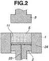
- the lower punch 2 is inserted into the die 1 from below to define a cavity 11 of predetermined volume between the upper surface of the lower punch 2 and the interior surface of the die 1 as shown in FIG. 2 .
- a powder material 5 is introduced into the cavity 11.
- the lower punch 2 is set at an appropriate position to adjust the volume of the cavity 11, and the cavity 11 is filled with the powder material 5 until the material is flush with the upper end of the die 1. Without a need for metering, this ensures that the charge of powder material 5 is always of the predetermined constant volume.
- FIGS. 3 and 4 The sequence from this state is shown in FIGS. 3 and 4 .
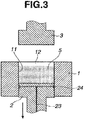
- the lower punch 2 is relatively moved down to define above the powder charge 5 a temporary cavity 12 for allowing the upper punch 3 to enter the through hole of the die 1 ( FIG. 3 ).
- the upper punch 3 is relatively moved down into the temporary cavity 12 to establish the state of FIG. 4 that the upper punch 3 abuts against the top of the powder charge 5.
- the sequence of once defining the temporary cavity 12 and then moving the upper punch 3 into the die prevents part of the powder charge 5 from overflowing beyond the upper end of the die 1 under the influence of air pressure induced by the advance of the upper punch 3 or the like.
- a magnetic field producing means is preferably arranged within or around the die 1, so that a magnetic field may be applied across the powder charge 5 in the die 1.
- This arrangement ensures that when a rare earth sintered magnet is manufactured using a rare earth alloy powder as the powder material 5, a magnetic field is applied across the rare earth alloy powder 5 in the cavity 11 for magnetization, dispersion and orientation.
- the rare earth alloy powder which is magnetized, dispersed and oriented under the applied magnetic field is then shaped by compression molding. The resulting rare earth sintered magnet is thus improved in magnetic properties.
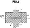
- the lower punch 3 is moved down to compress the powder charge 5 under a predetermined pressure, to form a compact 51 of predetermined shape (typically rectangular block) within the die 1 and between the upper and lower punches 3 and 2.
- a predetermined pressure typically rectangular block
- the upper punch 3 is moved toward the fixed lower punch 2 to compress the powder charge 5 in FIG. 5
- the lower punch 2 is also moved up to exert a pressure whereby the powder material 5 is compressed by the pressures of both the upper and lower punches 3 and 2.
- FIGS. 6 and 7 After the compact 51 is molded in this way, the sequence is shown in FIGS. 6 and 7 .
- the upper punch 3 is relatively moved up and retracted from the die 1 whereby the upper end of the die 1 is opened (or kept accessible) as shown in FIG. 6 .
- the lower punch 2 is relatively moved up to eject the compact 51 as shown in FIG. 7 , and the compact 51 is ejected from the open upper end of the die 1.
- FIGS. 6 and 7 the sequence of moving up the upper punch 3 to make the upper end of the die 1 open, and moving up the lower punch 2 to eject the compact 51 from the upper end of the die 1 is illustrated in FIGS.
- the (clamping) pressure under which the compact 51 is clamped between the upper and lower punches 3 and 2 when the compact 51 is ejected from the die 1 is preferably set lower than the pressure of the molding step. It is acceptable that the pressure of the molding step is once released, and compression is conducted again to set a predetermined pressure.
- the step of reducing the pressure of the molding step may be interrupted midway at a predetermined intermediate pressure. While the predetermined intermediate pressure is held, the ejection step may be performed.
- the clamping pressure during movement of the upper and lower punches 3 and 2 for ejection may be kept constant, or gradually increased or decreased during movement of the upper and lower punches 3 and 2. The gradual decrease of the clamping pressure during the ejection step is effective for preventing the compact from being cracked or chipped due to an abrupt change of pressure.
- the compact 51 on the lower punch 2 is removed by any suitable means. Thereafter, the lower punch 2 is relatively moved down, resuming the state of FIG. 1 . The die 1, lower punch 2 and upper punch 3 are cleaned if necessary, and the above-mentioned operation is repeated. In this way, the molding of powder material 5 is continuously carried out.
- a lubricant supply (not shown) is actuated to pump the lubricant through the lubricant conduit 23 to the discharge ports 22 in the lower punch 2 whereby a predetermined amount of the lubricant is discharged from the ports 22 to the pad 24 whereby the pad 24 is impregnated with an appropriate amount of the lubricant.
- the molding operation is repeated.
- the lubricant is discharged out of the pad 24 and applied to the entire interior surface of the die 1.
- the molding operation is repeated while the die interior surface is effectively covered with a coating of the lubricant at all times.
- the lubricant coating is effective for reducing the friction between the upper and lower punches 3 and 2 and the interior surface of the die 1 and facilitating the release of the compact.
- effective powder pressing is possible.
- the compact 51 of rare earth alloy powder thus molded is subjected to sintering heat treatment by any conventional method and well-known post-treatment whereby a rare earth sintered magnet is obtained.
- the powder molding apparatus described herein operates to compression mold a powder material while the band-like pad 24 fitted around the outer periphery of the lower punch 2 is always impregnated with lubricant.
- the lubricant in the pad 24 is applied to the interior surface of the die 1.
- the lower punch 2 travels all over that portion of the die interior surface subject to molding and all over that portion of the die interior surface where the upper punch 3 slides, ensuring that lubricant is applied to all the necessary portions of the die interior surface.
- the pad 24 slides along the die interior surface in close contact therewith, during which the lubricant in the pad 24 is evenly applied to the die interior surface.
- the powder molding apparatus ensures that molding operation assisted by even consistent coating of the lubricant can be continuously carried out without a need to interrupt the molding operation.
- a compact of rare earth alloy can be compression molded in a highly efficient manner. That is, using the powder molding apparatus, a rare earth sintered magnet can be efficiently manufactured.
- a Nd base magnet alloy consisting of 25.0 wt% Nd, 7.0 wt% Pr, 1.0 wt% Co, 1.0 wt% B, 0.2 wt% Al, 0.1 wt% Zr, 0.2 wt% Cu, and the balance of Fe was coarsely crushed by hydrogen decrepitation, and finely ground by a jet mill, obtaining a fine powder (rare earth sintered magnet-forming alloy powder) with an average particle size of 3.2 ⁇ m.
- the fine powder was pressed into a compact, which was sintered into a rare earth sintered magnet.
- the lubricant used herein is a solution of 0.03% stearic acid in a hydrofluoroether solvent (AE3000 by Asahi Glass Co., Ltd.).
- the pad 24 used herein was 3D non-woven fabric of 1.2 mm thick (Ecsaine® by Toray Industries, Inc., maximum lubricant impregnation amount ⁇ 0.11 g/cm 2 ).
- the molding operation is as follows.
- the lower punch 2 was relatively moved up and introduced into the die 1 from below to define a cavity 11 between the upper surface of the lower punch 2 and the interior surface of the die 1 as shown in FIG. 2 .
- the cavity 11 was filled with the powder material 5.
- the amount of the powder material 5 was adjusted such that the powder charge in the cavity 11 might have a density of 1.9 g/cm 3 .
- the lower punch 2 was relatively moved down to define above the powder charge 5 a temporary cavity 12 for allowing the upper punch 3 to move into the die 1.
- the upper punch 3 was relatively moved down, inserted into the temporary cavity 12 and set at the position where the upper punch 3 abutted against the top of the powder charge 5 ( FIG. 4 ).
- the magnetic field producing means (not shown) arranged around the die 1 was actuated to apply a magnetic field of 0.1 T across the powder charge for magnetizing and orienting powder particles.
- the upper punch 3 was moved down to compress the powder charge 5 under a predetermined pressure until the powder charge reached a density of 3.8 g/cm 3 , forming the compact 51 as shown in FIG. 5 .
- a weak magnetic field in opposite direction was applied for demagnetization treatment.
- the upper punch 3 was relatively moved up and retracted from the die 1 to open the upper end of the die 1 ( FIG. 6 ).
- the lower punch 2 was relatively moved up to eject the compact 51.
- the compact 51 was removed from the open upper end of the die 1.
- the compact 51 thus recovered was sintered at 1,050°C and heat treated at 500°C in a standard manner, obtaining a rare earth sintered magnet.
- the lubricant supply (not shown) was actuated to pump the lubricant through the conduit 23 to the ports 22 in the lower punch 2, thereby discharging a predetermined amount of the lubricant from the ports 22 to the pad 24 whereby the pad 24 was impregnated with an appropriate amount of the lubricant.
- the lubricant was applied from the pad 24 to the interior surface of the die 1. Particularly when the lower punch 2 was moved up from FIG. 6 to FIG. 7 , the lubricant was applied to the overall portion of the die interior surface subject to molding. The molding operation could be repeated without a need for a special step of applying the lubricant.
- the molding apparatus was operated all day long excluding quiescent times of inspection necessary for safety confirmation and adjustment of the system.
- the molding operation was repeated over 30 days.
- a cycle time, number of passed parts, number of failed parts, and number of mold adjustments were examined.
- the results are shown in Table 1.
- the resulting compacts 51 were sintered at 1,050°C and heat treated at 500°C in a standard manner, obtaining rare earth sintered magnets.
- a compact was molded under the same conditions as in Experiment 1 except that the pad 24 was a felt pad of 0.49 mm thick having a maximum lubricant impregnation amount of ⁇ 0.04 g/cm 2 .
- the compact was similarly sintered and heat treated, obtaining a rare earth sintered magnet.
- the cycle time, number of pass parts, number of failed parts, and number of mold adjustments were examined during 30 days of molding operation. The results are shown in Table 1.
- the pad 24 was omitted, and the lubricant was not supplied from the lower punch. Instead, the lubricant was sprayed through a spray nozzle to the interior surface of the die 1 in the state of FIG. 1 .
- the spray nozzle was mounted on a robot so that the spray position might be adjusted. The step of spraying the lubricant took 15 seconds. Otherwise under the same conditions as in Experiment 1, a compact of alloy powder was molded, sintered and heat treated, obtaining a rare earth sintered magnet. As in Experiment 1, the cycle time, number of pass parts, number of failed parts, and number of mold adjustments were recorded during 30 days of molding operation. The results are shown in Table 1.
Landscapes
- Chemical & Material Sciences (AREA)
- Engineering & Computer Science (AREA)
- Mechanical Engineering (AREA)
- Organic Chemistry (AREA)
- Materials Engineering (AREA)
- Metallurgy (AREA)
- Power Engineering (AREA)
- Manufacturing & Machinery (AREA)
- Crystallography & Structural Chemistry (AREA)
- Inorganic Chemistry (AREA)
- Powder Metallurgy (AREA)
- Manufacturing Cores, Coils, And Magnets (AREA)
- Dispersion Chemistry (AREA)
- Chemical Kinetics & Catalysis (AREA)
- General Chemical & Material Sciences (AREA)
- Oil, Petroleum & Natural Gas (AREA)
- Physics & Mathematics (AREA)
- Electromagnetism (AREA)
Abstract
Description
- This invention relates to powder molding apparatus and a method for the manufacture of rare earth sintered magnet using the apparatus.
- Because of excellent magnetic properties, rare earth sintered magnets as typified by Nd magnets are now widely used in motors, sensors and other components utilized in hard disk drives, air conditioners, hybrid vehicles and the like.
- In general, rare earth sintered magnets are manufactured by the powder metallurgy via the following steps. First, raw materials are blended in accordance with a predetermined composition, melted in an induction melting furnace or the like, and cast into an alloy ingot. The alloy ingot is coarsely crushed by a grinding machine such as a jaw crusher, Brown mill or pin mill, or by the hydrogen decrepitation process, and then finely ground by a jet mill or the like into a fine powder with an average particle size of 1 to 10 µm. The powder is pressed into a compact of desired shape in a magnetic field for imparting magnetic anisotropy, followed by sintering and heat treatment.
- The in-magnetic-field pressing process involved in the manufacture of rare earth sintered magnets by general powder metallurgy is a die pressing process comprising the steps of using a mold composed of a die, an upper punch and a lower punch, filling a cavity defined between the die and the lower punch with fine powder, and uniaxially pressing the powder between the upper and lower punches. It is a common practice to apply a lubricant to the interior surface of the die for reducing the friction between the upper and lower punches and the die interior surface and facilitating the release of the compact.
- For the lubricant application, the method of spraying the lubricant onto the interior surface of the die is generally employed. With this method, the molding operation is interrupted at every molding step or after a predetermined number of molding cycles, to take a time for lubricant applying operation. This means that the lubricant applying operation causes a lowering of productivity. It would be desirable to have a measure capable of efficiently applying the lubricant for thereby improving the productivity of rare earth sintered magnets.
-
- Patent Document 1:
JP-A H04-214803 - Patent Document 2:
JP-A H09-104902 - Patent Document 3:
JP-A 2000-197997 - Patent Document 4:
JP-A 2003-025099 - Patent Document 5:
JP-A 2006-187775 - An object of the invention is to provide a powder molding apparatus comprising a die, an upper punch, and a lower punch adapted to relatively move up and down, which is designed so as to efficiently apply a lubricant to a necessary portion during compression molding of powder material, without a lowering of productivity, and a corresponding method, especially for the manufacture of rare earth sintered magnets, using the apparatus.
- In one aspect, the invention provides a powder molding apparatus comprising a die, an upper punch, and a lower punch adapted to relatively move up and down, the die having a through hole surrounded by an interior surface and extending between upper and lower ends, the upper punch having a lower surface, the lower punch having an upper surface, the apparatus being operated by moving the lower punch into the die from below to define a cavity between the upper surface of the lower punch and the interior surface of the die, introducing a powder material into the cavity, moving the upper punch into the die from above to compress the powder material between the upper and lower punches under pressure for thereby molding the powder material into a compact of desired shape, relatively moving up the upper punch until the die is opened at the upper end, relatively moving up the lower punch to eject the compact, and removing the compact from the upper end of the die. According to the invention, the lower punch is provided with a band-like channel around its entire periphery, an applicator or pad made of an elastic material which may be impregnated with a lubricant is fitted in the channel, the lower punch is provided with a lubricant conduit for feeding the lubricant to the pad. With this construction, the lubricant is fed to the pad through the lubricant conduit to impregnate the pad with the lubricant, the lubricant is applied from the pad to the die interior surface as the lower punch is relatively moved up and down in the die during the molding operation, and the lubricant applying operation is repeated whenever the molding operation is repeated.
- Preferably, the pad is made of a felt, non-woven fabric or sponge material. Preferably it can be impregnated with at least 0.01 g/cm2 of the lubricant.
- Preferably the powder molding apparatus further comprises means for applying a magnetic field across the cavity between the upper surface of the lower punch and the interior surface of the die. Preferably the powder material is a rare earth alloy powder, the magnetic field is applied on the rare earth alloy powder for magnetization, dispersion and orientation, and in this state, the compression molding is carried out to form a compact of rare earth alloy.
- Preferably, while the compact is clamped between the upper and lower punches under a predetermined pressure by compressing the compact by the upper punch and/or the lower punch, the compact is ejected from the die by moving up the upper and lower punches relative to the die. More preferably, the compact is ejected from the die by moving up the upper and lower punches relative to the die while the compact is clamped between the upper and lower punches under a predetermined pressure, and the clamping pressure is increased or decreased during the movement of the upper and lower punches.
- Preferably the lubricant is at least one agent selected from the group consisting of stearic acid, zinc stearate, calcium stearate, methyl oleate, capric acid, lauric acid, myristic acid, palmitic acid, arachidic acid, behenic acid, and lignoceric acid, usually dissolved in a suitable volatile solvent.
- The apparatus is operable to carry out the method steps described. In another aspect, the invention provides a molding method using such apparatus. A particular method aspect herein is a method for manufacturing a rare earth sintered magnet comprising the steps of compression molding a rare earth alloy powder into a compact, and heat treating the compact for sintering, the compression molding step using the powder molding apparatus defined above.
- Specifically, in the powder molding apparatus of the invention, compression molding of powder material is carried out while the band-form pad fitted around the periphery of the lower punch is impregnated with the lubricant. Then lubricant can be applied from the pad to the interior surface of the die on every molding operation or whenever the lower punch is moved up and down in the die. Since the operation to define within the die the cavity to be filled with the powder material and the operation to eject the compact cause the lower punch to move all over a portion of the die interior surface subject to pressing and a portion of the die interior surface along which the upper and lower punches slide, the lubricant can be applied to overall the necessary portion of the die interior surface. In addition, since the pad of elastic material fitted around the periphery of the lower punch may slide in constant and tight contact with the die interior surface due to its elasticity, the lubricant is evenly and effectively applied from the pad to the die interior surface. This reduces the friction between the upper and lower punches and the die and facilitates the release of the compact. Effective powder pressing is possible.
- The powder molding apparatus of the invention enables continuous molding of powder material while applying the lubricant at the same time as the molding operation, without interrupting the molding operation. Compression molding of a compact of rare earth alloy or the like is possible at a high efficiency. Using the powder molding apparatus, rare earth sintered magnets can be efficiently manufactured.
-
-
FIG. 1 is a schematic cross-sectional view of a powder molding apparatus including a die, an upper punch and a lower punch according to one embodiment of the invention. -
FIG. 2 is a schematic cross-sectional view of the powder molding apparatus in which the cavity defined by the upper surface of the lower punch and the interior surface of the die is filled with powder material. -
FIG. 3 is a schematic cross-sectional view of the powder molding apparatus in which the lower punch is relatively moved down to define a temporary cavity for allowing the upper punch to rest on the powder material. -
FIG. 4 is a schematic cross-sectional view of the powder molding apparatus in which the upper punch is inserted into the die from above until the upper punch abuts against the powder material. -
FIG. 5 is a schematic cross-sectional view of the powder molding apparatus in which the powder material in the die is compressed between the upper and lower punches into a compact of desired shape. -
FIG. 6 is a schematic cross-sectional view of the powder molding apparatus in which the upper punch is relatively moved up until the upper end of the die is opened. -
FIG. 7 is a schematic cross-sectional view of the powder molding apparatus in which the lower punch is relatively moved up to eject the compact so that the compact may be removed from the open upper end of the die. -
FIG. 8 is a perspective view of the lower punch. - In the following description, like reference characters designate like or corresponding parts throughout the several views shown in the figures. It is also understood that terms such as "top," "bottom," "upper," "lower," and the like are words of convenience and are not to be construed as limiting terms. The term "relative" or "relatively" is used in the sense that either the punch or the die or both may be moved toward and away from each other.
- Briefly stated, the powder molding apparatus includes a die, an upper punch, and a lower punch adapted to relatively move up and down. A powder charge is compression molded in the die between the upper and lower punches into a compact of desired shape. The method comprises the steps of compression molding a rare earth alloy powder into a compact using the powder molding apparatus, and heat treating the compact for sintering, thereby yielding a rare earth sintered magnet. One exemplary powder molding apparatus is illustrated in
FIGS. 1 to 7 . -
FIGS. 1 to 7 illustrate an overall process from the step of compression molding a powder material using the powder molding apparatus in one embodiment to the step of removing the molded compact of powder material. The powder molding apparatus is illustrated inFIG. 1 as comprising adie 1 of rectangular column shape, alower punch 2 of rectangular block shape adapted to move into thedie 1 from below, and anupper punch 3 of rectangular block shape adapted to move into thedie 1 from above. As working surfaces, thedie 1 has a through hole surrounded by an interior surface and axially extending between upper and lower ends, theupper punch 3 has a lower surface, and thelower punch 2 has an upper surface. They are arranged such that the lower surface ofupper punch 3 and the upper surface oflower punch 2 are axially opposed through the through hole of thedie 1. - The
die 1,lower punch 2 andupper punch 3 are adapted to move up and down relatively along a common axis 4. For example, as thelower punch 2 moves up and/or thedie 1 moves down, thelower punch 2 enters the through hole of thedie 1 from below and moves to the upper end of thedie 1. By relative movement oflower punch 2 and die 1, thelower punch 2 moves up and down within thedie 1. Likewise, as theupper punch 3 moves down and/or thedie 1 moves up, theupper punch 3 enters the through hole of thedie 1 from above. By relative movement ofupper punch 3 and die 1, theupper punch 3 moves up and down within thedie 1. - Referring to
FIG. 8 , thelower punch 2 at its top is provided around the entire peripheral surface with a rectangular band-form (or loop-like)channel 21. Thechannel 21 is perforated with a predetermined number (3 ports per side, total 12 ports on four sides) of equi-spaceddischarge ports 22 in fluid communication with a lubricant conduit 23 (shown inFIGS. 1 to 7 ) drilled in thelower punch 2. A lubricant supply (not shown) is actuated to pump a lubricant through theconduit 23 and discharge the lubricant through theports 22 when necessary. - An
applicator pad 24 is fitted in thechannel 21. Thepad 24 is made of an elastic material which may be impregnated with the lubricant. That is, thepad 24 is impregnated with the lubricant to be discharged through theports 22. Thepad 24 protrudes a distance of about 10 to 1,000 µm from the periphery of thelower punch 2 so that thepad 24 is kept in tight contact with the interior surface of thedie 1 under an appropriate pressure when thelower punch 2 moves into the through hole of thedie 1. As thelower punch 2 moves up and down relatively within thedie 1, the lubricant is automatically discharged from thepad 24 and applied to the interior surface of thedie 1. - The
pad 24 may be made of any elastic material as long as it may be impregnated with the lubricant. It may be chosen from well-known materials, for example, felt, non-woven fabric and sponge materials. Preferably the pad of elastic material is able to hold at least 0.01 g/cm2, more preferably at least 0.04 g/cm2, and even more preferably at least 0.1 g/cm2 of the impregnated lubricant, although the impregnation amount is not particularly limited. An appropriate impregnation amount may be achieved by adjusting the thickness of the elastic material or the like. If the impregnation amount is less than 0.01 g/cm2, a coating amount sufficient to exert a satisfactory lubricating effect may not be obtained depending on the type of lubricant. - The lubricant used herein is not particularly limited. Any of well-known lubricants used in compression molding of powder may be used. Suitable lubricants include stearic acid, zinc stearate, calcium stearate, methyl oleate, capric acid, lauric acid, myristic acid, palmitic acid, arachidic acid, behenic acid, and lignoceric acid. One or more lubricants are preferably dissolved in a volatile solvent in order to apply the lubricant thinly and evenly. Any appropriate volatile solvent may be selected depending on the type of lubricant. A choice is preferably made among those solvents which evaporate at or below the temperature of 150°C so that they may evaporate off prior to reaction with the rare earth element during sintering of a compact, for example, fluorocarbons and alcohols having a boiling point in the range of 50 to 150°C.
- Using the powder molding apparatus, a powder material such as rare earth alloy powder is compression molded as follows. First, the
lower punch 2 is relatively moved up from the state ofFIG. 1 . Thelower punch 2 is inserted into thedie 1 from below to define acavity 11 of predetermined volume between the upper surface of thelower punch 2 and the interior surface of thedie 1 as shown inFIG. 2 . Apowder material 5 is introduced into thecavity 11. At this point, thelower punch 2 is set at an appropriate position to adjust the volume of thecavity 11, and thecavity 11 is filled with thepowder material 5 until the material is flush with the upper end of thedie 1. Without a need for metering, this ensures that the charge ofpowder material 5 is always of the predetermined constant volume. - The sequence from this state is shown in
FIGS. 3 and4 . Thelower punch 2 is relatively moved down to define above the powder charge 5 atemporary cavity 12 for allowing theupper punch 3 to enter the through hole of the die 1 (FIG. 3 ). Theupper punch 3 is relatively moved down into thetemporary cavity 12 to establish the state ofFIG. 4 that theupper punch 3 abuts against the top of thepowder charge 5. The sequence of once defining thetemporary cavity 12 and then moving theupper punch 3 into the die prevents part of thepowder charge 5 from overflowing beyond the upper end of thedie 1 under the influence of air pressure induced by the advance of theupper punch 3 or the like. - Though not shown, a magnetic field producing means is preferably arranged within or around the
die 1, so that a magnetic field may be applied across thepowder charge 5 in thedie 1. This arrangement ensures that when a rare earth sintered magnet is manufactured using a rare earth alloy powder as thepowder material 5, a magnetic field is applied across the rareearth alloy powder 5 in thecavity 11 for magnetization, dispersion and orientation. The rare earth alloy powder which is magnetized, dispersed and oriented under the applied magnetic field is then shaped by compression molding. The resulting rare earth sintered magnet is thus improved in magnetic properties. - Next, as shown in
FIG. 5 , thelower punch 3 is moved down to compress thepowder charge 5 under a predetermined pressure, to form a compact 51 of predetermined shape (typically rectangular block) within thedie 1 and between the upper andlower punches upper punch 3 is moved toward the fixedlower punch 2 to compress thepowder charge 5 inFIG. 5 , it is acceptable that thelower punch 2 is also moved up to exert a pressure whereby thepowder material 5 is compressed by the pressures of both the upper andlower punches - After the compact 51 is molded in this way, the sequence is shown in
FIGS. 6 and7 . Theupper punch 3 is relatively moved up and retracted from thedie 1 whereby the upper end of thedie 1 is opened (or kept accessible) as shown inFIG. 6 . Thelower punch 2 is relatively moved up to eject the compact 51 as shown inFIG. 7 , and the compact 51 is ejected from the open upper end of thedie 1. At this point, although the sequence of moving up theupper punch 3 to make the upper end of thedie 1 open, and moving up thelower punch 2 to eject the compact 51 from the upper end of thedie 1 is illustrated inFIGS. 6 and7 , it is acceptable that while theupper punch 3 and/orlower punch 2 is forced against the compact 51 under a predetermined pressure, that is, the compact 51 is clamped under a predetermined pressure between the upper andlower punches lower punches die 1. The ejection of the compact 51 from thedie 1, with the compact 51 held under pressure, is effective for preventing the compact from being cracked or chipped during the ejection step. - It is noted that the (clamping) pressure under which the compact 51 is clamped between the upper and
lower punches die 1 is preferably set lower than the pressure of the molding step. It is acceptable that the pressure of the molding step is once released, and compression is conducted again to set a predetermined pressure. Alternatively, the step of reducing the pressure of the molding step may be interrupted midway at a predetermined intermediate pressure. While the predetermined intermediate pressure is held, the ejection step may be performed. Also the clamping pressure during movement of the upper andlower punches lower punches - After the compact 51 is ejected beyond the upper end of the die 1 (
FIG. 7 ), the compact 51 on thelower punch 2 is removed by any suitable means. Thereafter, thelower punch 2 is relatively moved down, resuming the state ofFIG. 1 . Thedie 1,lower punch 2 andupper punch 3 are cleaned if necessary, and the above-mentioned operation is repeated. In this way, the molding ofpowder material 5 is continuously carried out. - In the powder molding apparatus, a lubricant supply (not shown) is actuated to pump the lubricant through the
lubricant conduit 23 to thedischarge ports 22 in thelower punch 2 whereby a predetermined amount of the lubricant is discharged from theports 22 to thepad 24 whereby thepad 24 is impregnated with an appropriate amount of the lubricant. In this state, the molding operation is repeated. In cooperation with the relative up/down movement of thelower punch 2 during the molding operation, the lubricant is discharged out of thepad 24 and applied to the entire interior surface of thedie 1. The molding operation is repeated while the die interior surface is effectively covered with a coating of the lubricant at all times. The lubricant coating is effective for reducing the friction between the upper andlower punches die 1 and facilitating the release of the compact. Thus effective powder pressing is possible. - When it is desired to manufacture a rare earth sintered magnet using a rare earth alloy powder as the
powder material 5, the compact 51 of rare earth alloy powder thus molded is subjected to sintering heat treatment by any conventional method and well-known post-treatment whereby a rare earth sintered magnet is obtained. - The powder molding apparatus described herein operates to compression mold a powder material while the band-
like pad 24 fitted around the outer periphery of thelower punch 2 is always impregnated with lubricant. As thelower punch 2 is moved up and down within thedie 1 on every molding operation, the lubricant in thepad 24 is applied to the interior surface of thedie 1. Herein, during the operation inFIGS. 1 to 3 of defining thecavity 11 to be filled with thepowder material 5 within thedie 1 and the operation inFIGS. 6 and7 of ejecting the compact 51, thelower punch 2 travels all over that portion of the die interior surface subject to molding and all over that portion of the die interior surface where theupper punch 3 slides, ensuring that lubricant is applied to all the necessary portions of the die interior surface. In addition, due to its elasticity, thepad 24 slides along the die interior surface in close contact therewith, during which the lubricant in thepad 24 is evenly applied to the die interior surface. - Accordingly, the powder molding apparatus ensures that molding operation assisted by even consistent coating of the lubricant can be continuously carried out without a need to interrupt the molding operation. A compact of rare earth alloy can be compression molded in a highly efficient manner. That is, using the powder molding apparatus, a rare earth sintered magnet can be efficiently manufactured.
- Experiments are given below for further illustrating the invention.
- A Nd base magnet alloy consisting of 25.0 wt% Nd, 7.0 wt% Pr, 1.0 wt% Co, 1.0 wt% B, 0.2 wt% Al, 0.1 wt% Zr, 0.2 wt% Cu, and the balance of Fe was coarsely crushed by hydrogen decrepitation, and finely ground by a jet mill, obtaining a fine powder (rare earth sintered magnet-forming alloy powder) with an average particle size of 3.2 µm. Using the molding apparatus shown in
FIGS. 1 to 8 , the fine powder was pressed into a compact, which was sintered into a rare earth sintered magnet. The lubricant used herein is a solution of 0.03% stearic acid in a hydrofluoroether solvent (AE3000 by Asahi Glass Co., Ltd.). Thepad 24 used herein was 3D non-woven fabric of 1.2 mm thick (Ecsaine® by Toray Industries, Inc., maximum lubricant impregnation amount ∼0.11 g/cm2). The molding operation is as follows. - From the state of
FIG. 1 , thelower punch 2 was relatively moved up and introduced into thedie 1 from below to define acavity 11 between the upper surface of thelower punch 2 and the interior surface of thedie 1 as shown inFIG. 2 . Thecavity 11 was filled with thepowder material 5. The amount of thepowder material 5 was adjusted such that the powder charge in thecavity 11 might have a density of 1.9 g/cm3. - From this state, as shown in
FIG. 3 , thelower punch 2 was relatively moved down to define above the powder charge 5 atemporary cavity 12 for allowing theupper punch 3 to move into thedie 1. Theupper punch 3 was relatively moved down, inserted into thetemporary cavity 12 and set at the position where theupper punch 3 abutted against the top of the powder charge 5 (FIG. 4 ). At this point, the magnetic field producing means (not shown) arranged around thedie 1 was actuated to apply a magnetic field of 0.1 T across the powder charge for magnetizing and orienting powder particles. With the applied magnetic field kept so as to prevent the orientation from being disordered, theupper punch 3 was moved down to compress thepowder charge 5 under a predetermined pressure until the powder charge reached a density of 3.8 g/cm3, forming the compact 51 as shown inFIG. 5 . At this point, since the compact was in the magnetized state, which suggested that the compact was fragile under the action of magnetic suction force during subsequent handling, a weak magnetic field in opposite direction was applied for demagnetization treatment. Thereafter, in sequence as shown inFIGS. 6 and7 , theupper punch 3 was relatively moved up and retracted from thedie 1 to open the upper end of the die 1 (FIG. 6 ). Thelower punch 2 was relatively moved up to eject the compact 51. Then the compact 51 was removed from the open upper end of thedie 1. The compact 51 thus recovered was sintered at 1,050°C and heat treated at 500°C in a standard manner, obtaining a rare earth sintered magnet. - During the above-mentioned sequence of molding operation, the lubricant supply (not shown) was actuated to pump the lubricant through the
conduit 23 to theports 22 in thelower punch 2, thereby discharging a predetermined amount of the lubricant from theports 22 to thepad 24 whereby thepad 24 was impregnated with an appropriate amount of the lubricant. Then, as thelower punch 2 was moved up and down, the lubricant was applied from thepad 24 to the interior surface of thedie 1. Particularly when thelower punch 2 was moved up fromFIG. 6 to FIG. 7 , the lubricant was applied to the overall portion of the die interior surface subject to molding. The molding operation could be repeated without a need for a special step of applying the lubricant. The molding apparatus was operated all day long excluding quiescent times of inspection necessary for safety confirmation and adjustment of the system. The molding operation was repeated over 30 days. A cycle time, number of passed parts, number of failed parts, and number of mold adjustments were examined. The results are shown in Table 1. The resultingcompacts 51 were sintered at 1,050°C and heat treated at 500°C in a standard manner, obtaining rare earth sintered magnets. - A compact was molded under the same conditions as in
Experiment 1 except that thepad 24 was a felt pad of 0.49 mm thick having a maximum lubricant impregnation amount of ∼0.04 g/cm2. The compact was similarly sintered and heat treated, obtaining a rare earth sintered magnet. As inExperiment 1, the cycle time, number of pass parts, number of failed parts, and number of mold adjustments were examined during 30 days of molding operation. The results are shown in Table 1. - The
pad 24 was omitted, and the lubricant was not supplied from the lower punch. Instead, the lubricant was sprayed through a spray nozzle to the interior surface of thedie 1 in the state ofFIG. 1 . The spray nozzle was mounted on a robot so that the spray position might be adjusted. The step of spraying the lubricant took 15 seconds. Otherwise under the same conditions as inExperiment 1, a compact of alloy powder was molded, sintered and heat treated, obtaining a rare earth sintered magnet. As inExperiment 1, the cycle time, number of pass parts, number of failed parts, and number of mold adjustments were recorded during 30 days of molding operation. The results are shown in Table 1.Table 1 Cycle time (sec/part) Number of pass parts (/30 days) Number of failed parts (/30 days) Number of mold adjustments Remarks Experiment 1 52 47,340 14 0 satisfactory molded state continued over 30 days Experiment 2 52 46,315 42 1 due to breakage, felt (as pad 24) was replaced once Experiment 367 32,588 296 4 due to flaws, the die was polished - In
Experiments pad 24, the mold received little or no flaws, and so a lowering of availability by mold polishing operation was prevented. InExperiment 2, the felt pad was once broken because of its thinness, but after replacement, the molding operation could be continued without problems. - The entire disclosure of Japanese Patent Application No.
2015-043326 - Although some preferred embodiments have been described, many modifications and variations may be made thereto in light of the above teachings. It is therefore to be understood that the invention may be practised otherwise than as specifically described without departing from the scope of the appended claims or the general teachings herein.
- In respect of numerical ranges disclosed in the present description it will of course be understood that in the normal way the technical criterion for the upper limit is different from the technical criterion for the lower limit, i.e. the upper and lower limits are intrinsically distinct proposals.
- For the avoidance of doubt it is confirmed that in the general description above, in the usual way the proposal of general preferences and options in respect of different features of the molding apparatus and molding method constitutes the proposal of general combinations of those general preferences and options for the different features, insofar as they are combinable and compatible and are put forward in the same context.
Claims (11)
- Powder molding apparatus comprising a die, an upper punch, and a lower punch adapted to relatively move up and down, the die having a through hole surrounded by an interior surface and extending between upper and lower ends, the upper punch having a lower surface, the lower punch having an upper surface, the apparatus being operable in a method comprising moving the lower punch into the die from below to define a cavity between the upper surface of the lower punch and the interior surface of the die, for introduction of a powder material into the cavity, moving the upper punch into the die from above to compress such powder material between the upper and lower punches under pressure to mold the powder material into a compact of desired shape, relatively moving up the upper punch until the die is opened at the upper end, relatively moving up the lower punch to eject the compact, and removing the compact from the upper end of the die, wherein
the lower punch is provided with a band-form channel around its periphery, a pad of elastic material and able to be impregnated with lubricant fitted in the channel, and a lubricant conduit for feeding lubricant to the pad,
whereby in the method lubricant fed to the pad through the lubricant conduit impregnates the pad with the lubricant and the lubricant is applied from the pad to the die interior surface as the lower punch is relatively moved up and down in the die during the molding operation. - Powder molding apparatus of claim 1 wherein the pad is made of a felt, non-woven fabric or sponge and may be impregnated with at least 0.01 g/cm2 of the lubricant.
- Powder molding apparatus of claim 1 or 2, further comprising means for applying a magnetic field across the cavity.
- Powder molding apparatus of claim 3 for molding a powder material which is a rare earth alloy powder, and operable to apply the magnetic field to the rare earth alloy powder for magnetization, dispersion and orientation, and in this state, carry out the compression molding to form a compact of rare earth alloy.
- Powder molding apparatus of any one of claims 1 to 4 operable to clamp the compact between the upper and lower punches under a predetermined pressure by compressing the compact by the upper punch and/or the lower punch, and to eject the compact from the die by moving the upper and lower punches up relative to the die.
- Powder molding apparatus of claim 5 operable to eject the compact from the die by moving the upper and lower punches up relative to the die while the compact is clamped between the upper and lower punches under a predetermined pressure, and to increase or decrease the clamping pressure during the movement of the upper and lower punches.
- Powder molding apparatus of any one of claims 1 to 6 wherein the lubricant is at least one selected from stearic acid, zinc stearate, calcium stearate, methyl oleate, capric acid, lauric acid, myristic acid, palmitic acid, arachidic acid, behenic acid, and lignoceric acid, dissolved in a volatile solvent.
- A method for manufacturing a rare earth sintered magnet comprising the steps of compression molding a rare earth alloy powder into a compact, and heat treating the compact for sintering, the compression molding step using powder molding apparatus of any one of claims 1 to 7.
- Method of claim 8 wherein while the compact is clamped between the upper and lower punches under a predetermined pressure, by compressing the compact by the upper punch and/or the lower punch, the compact is ejected from the die by moving the upper and lower punches up relative to the die.
- Method of claim 8 or 9 wherein the compact is ejected from the die by moving the upper and lower punches up relative to the die while the compact is clamped between the upper and lower punches under a predetermined pressure, and the clamping pressure is increased or decreased during the movement of the upper and lower punches.
- Method of any one of claims 8 to 10 wherein the lubricant comprises at least one selected from stearic acid, zinc stearate, calcium stearate, methyl oleate, capric acid, lauric acid, myristic acid, palmitic acid, arachidic acid, behenic acid and lignoceric acid, dissolved in a solvent.
Applications Claiming Priority (1)
| Application Number | Priority Date | Filing Date | Title |
|---|---|---|---|
| JP2015043326A JP6689571B2 (en) | 2015-03-05 | 2015-03-05 | Rare earth sintered magnet manufacturing method |
Publications (2)
| Publication Number | Publication Date |
|---|---|
| EP3067191A1 true EP3067191A1 (en) | 2016-09-14 |
| EP3067191B1 EP3067191B1 (en) | 2023-06-14 |
Family
ID=55910705
Family Applications (1)
| Application Number | Title | Priority Date | Filing Date |
|---|---|---|---|
| EP16157554.3A Ceased EP3067191B1 (en) | 2015-03-05 | 2016-02-26 | Powder molding apparatus and manufacture of rare earth sintered magnet using the apparatus |
Country Status (7)
| Country | Link |
|---|---|
| US (2) | US10607773B2 (en) |
| EP (1) | EP3067191B1 (en) |
| JP (1) | JP6689571B2 (en) |
| KR (1) | KR20160108180A (en) |
| CN (1) | CN105935766B (en) |
| RU (1) | RU2710812C2 (en) |
| TW (1) | TWI671145B (en) |
Families Citing this family (13)
| Publication number | Priority date | Publication date | Assignee | Title |
|---|---|---|---|---|
| US11167517B2 (en) * | 2015-08-25 | 2021-11-09 | Sumitomo Electric Industries, Ltd. | Powder compaction mold and method for manufacturing powder compact |
| CN106424498B (en) * | 2016-09-30 | 2018-01-12 | 中国南方航空工业(集团)有限公司 | A kind of manufacturing process of arc forging and the mould used |
| CN106270330B (en) * | 2016-09-30 | 2018-12-14 | 中国南方航空工业(集团)有限公司 | A kind of forging method of high temperature alloy arc-shaped workpiece |
| KR102448157B1 (en) * | 2017-05-29 | 2022-09-27 | 미쓰비시 마테리알 가부시키가이샤 | Powder molding press method and powder molding press apparatus for green compact for cutting inserts |
| KR101799498B1 (en) * | 2017-08-10 | 2017-11-20 | 박병곤 | Powder Forming Mold Possible Supply of Lubricant and Powder Molding Method Using it |
| CN110346020B (en) * | 2018-04-04 | 2024-11-26 | 广东科达洁能股份有限公司 | Powder metering device and automated production line |
| CN110568219B (en) * | 2019-08-27 | 2021-06-15 | 北京自动化控制设备研究所 | Molecular electronic angular accelerometer electromechanical converter sintering device and method |
| JP7262425B2 (en) * | 2020-06-18 | 2023-04-21 | 株式会社日本製鋼所 | Electric sintering method and electric sintering apparatus |
| CN112103071B (en) * | 2020-09-18 | 2022-02-11 | 江西荧光磁业有限公司 | Neodymium iron boron magnetic powder forming and die casting device and implementation method thereof |
| KR102929919B1 (en) | 2020-09-25 | 2026-02-24 | 주식회사 엘지에너지솔루션 | Pouch-type battery case forming apparatus comprising volatile lubricant supply unit and method of manufacturing pouch-type battery case using the same |
| CN114918841A (en) * | 2022-02-28 | 2022-08-19 | 泉州众志新材料科技有限公司 | Preparation method of resin diamond abrasive disc |
| IT202300012897A1 (en) * | 2023-06-22 | 2024-12-22 | Off Mec Pontillo & C S R L | MACHINE FOR PRESSING METAL POWDERS |
| CN116727667B (en) * | 2023-08-16 | 2023-11-17 | 沈阳拓普新材料有限公司 | Powder metallurgy forming die |
Citations (9)
| Publication number | Priority date | Publication date | Assignee | Title |
|---|---|---|---|---|
| US3676030A (en) * | 1969-04-22 | 1972-07-11 | Nukem Gmbh | Apparatus for lubrication of compression tools for powder metallurgical purposes |
| JPH03291307A (en) * | 1990-04-05 | 1991-12-20 | Nkk Corp | Mold lubrication method and mold lubrication device |
| JPH04214803A (en) | 1991-02-28 | 1992-08-05 | Sumitomo Special Metals Co Ltd | Method for molding alloy powder for rare earth-iron-boron based permanent magnet |
| JPH09104902A (en) | 1995-10-05 | 1997-04-22 | Shin Etsu Chem Co Ltd | Powder molding method |
| JP2000197997A (en) | 1998-11-02 | 2000-07-18 | Sumitomo Special Metals Co Ltd | Compacting device and compacting method |
| JP2003025099A (en) | 2001-07-12 | 2003-01-28 | Sumitomo Special Metals Co Ltd | Powder pressing apparatus and powder pressing method |
| JP2006187775A (en) | 2004-12-28 | 2006-07-20 | Tdk Corp | Apparatus and method for molding powder |
| WO2012147462A1 (en) * | 2011-04-28 | 2012-11-01 | 住友電気工業株式会社 | Method for forming pressed powder compact |
| JP2015043326A (en) | 2010-11-12 | 2015-03-05 | 東芝ライテック株式会社 | LED lighting device and LED lighting device |
Family Cites Families (27)
| Publication number | Priority date | Publication date | Assignee | Title |
|---|---|---|---|---|
| DE2629990C3 (en) * | 1976-07-03 | 1981-01-15 | Magnetfabrik Bonn Gmbh Vorm. Gewerkschaft Windhorst, 5300 Bonn | Press tool for anisotropic permanent magnets |
| JPH0276695U (en) | 1988-11-21 | 1990-06-12 | ||
| JPH09168898A (en) | 1995-12-21 | 1997-06-30 | Toyota Auto Body Co Ltd | Powder magnetic field forming die |
| JPH108102A (en) * | 1996-06-19 | 1998-01-13 | Sumitomo Special Metals Co Ltd | Press compact method for magnetic alloy powder |
| JP3445112B2 (en) * | 1997-09-25 | 2003-09-08 | 日立粉末冶金株式会社 | Powder metallurgy in powder metallurgy, lubrication of molding dies and stamping dies |
| US6482349B1 (en) | 1998-11-02 | 2002-11-19 | Sumitomo Special Metals Co., Ltd. | Powder pressing apparatus and powder pressing method |
| US6432158B1 (en) * | 1999-10-25 | 2002-08-13 | Sumitomo Special Metals Co., Ltd. | Method and apparatus for producing compact of rare earth alloy powder and rare earth magnet |
| JP3233359B2 (en) | 2000-03-08 | 2001-11-26 | 住友特殊金属株式会社 | Method for producing rare earth alloy magnetic powder compact and method for producing rare earth magnet |
| JP2002086300A (en) | 2000-09-11 | 2002-03-26 | Takako:Kk | Powder molding method and powder molding apparatus |
| US6423673B1 (en) | 2001-09-07 | 2002-07-23 | 3M Innovation Properties Company | Azeotrope-like compositions and their use |
| TWI221619B (en) | 2002-04-24 | 2004-10-01 | Mitsubishi Electric Corp | Apparatus for moulding permanent magnet |
| JP2004106041A (en) * | 2002-09-20 | 2004-04-08 | Sumitomo Special Metals Co Ltd | Press, and manufacturing method of magnet |
| JP4178546B2 (en) * | 2002-11-21 | 2008-11-12 | 三菱マテリアルPmg株式会社 | Molding method of powder molded body and sintered body |
| JP2004298891A (en) * | 2003-03-28 | 2004-10-28 | Mitsubishi Materials Corp | Powder molding die apparatus and powder molding method |
| JP2005277180A (en) | 2004-03-25 | 2005-10-06 | Tdk Corp | Magnet-manufacturing method, magnetic powder forming method and dry forming equipment |
| JP2006142313A (en) * | 2004-11-16 | 2006-06-08 | Mitsubishi Materials Pmg Corp | Powder molding die device, powder molding device, and powder molding method |
| JP5412013B2 (en) * | 2005-10-17 | 2014-02-12 | 株式会社カネカ | Medical catheter tube and manufacturing method thereof |
| JP2007217511A (en) | 2006-02-15 | 2007-08-30 | Nippon Koyu Ltd | Solvent dilution type fluorine lubricant composition |
| WO2008061342A1 (en) * | 2006-11-20 | 2008-05-29 | Stackpole Limited | Method and apparatus for die wall lubrication |
| JP2008272774A (en) * | 2007-04-26 | 2008-11-13 | Sumitomo Electric Ind Ltd | Powder mold and compacted body molded with the powder mold |
| JP2009012039A (en) * | 2007-07-04 | 2009-01-22 | Sumitomo Electric Ind Ltd | Powder mold, molded body and sintered body molded using the powder mold |
| KR101137395B1 (en) * | 2007-12-25 | 2012-04-20 | 가부시키가이샤 알박 | Method of manufacturing permanent magnet |
| JP4993135B2 (en) * | 2008-07-08 | 2012-08-08 | 信越化学工業株式会社 | Thermally conductive silicone composition |
| JPWO2012014746A1 (en) | 2010-07-30 | 2013-09-12 | 株式会社シクロケム | Alpha lipoic acid complex |
| JP2012234871A (en) * | 2011-04-28 | 2012-11-29 | Sumitomo Electric Ind Ltd | Forming method of green compact |
| JP5906054B2 (en) | 2011-10-14 | 2016-04-20 | 住友電気工業株式会社 | Molding method of green compact |
| JP6044504B2 (en) | 2012-10-23 | 2016-12-14 | トヨタ自動車株式会社 | Rare earth magnet manufacturing method |
-
2015
- 2015-03-05 JP JP2015043326A patent/JP6689571B2/en active Active
-
2016
- 2016-02-26 EP EP16157554.3A patent/EP3067191B1/en not_active Ceased
- 2016-03-02 US US15/058,395 patent/US10607773B2/en active Active
- 2016-03-02 KR KR1020160024979A patent/KR20160108180A/en not_active Withdrawn
- 2016-03-03 RU RU2016107712A patent/RU2710812C2/en active
- 2016-03-04 CN CN201610123817.7A patent/CN105935766B/en not_active Expired - Fee Related
- 2016-03-04 TW TW105106726A patent/TWI671145B/en not_active IP Right Cessation
-
2019
- 2019-10-29 US US16/666,726 patent/US20200066440A1/en not_active Abandoned
Patent Citations (9)
| Publication number | Priority date | Publication date | Assignee | Title |
|---|---|---|---|---|
| US3676030A (en) * | 1969-04-22 | 1972-07-11 | Nukem Gmbh | Apparatus for lubrication of compression tools for powder metallurgical purposes |
| JPH03291307A (en) * | 1990-04-05 | 1991-12-20 | Nkk Corp | Mold lubrication method and mold lubrication device |
| JPH04214803A (en) | 1991-02-28 | 1992-08-05 | Sumitomo Special Metals Co Ltd | Method for molding alloy powder for rare earth-iron-boron based permanent magnet |
| JPH09104902A (en) | 1995-10-05 | 1997-04-22 | Shin Etsu Chem Co Ltd | Powder molding method |
| JP2000197997A (en) | 1998-11-02 | 2000-07-18 | Sumitomo Special Metals Co Ltd | Compacting device and compacting method |
| JP2003025099A (en) | 2001-07-12 | 2003-01-28 | Sumitomo Special Metals Co Ltd | Powder pressing apparatus and powder pressing method |
| JP2006187775A (en) | 2004-12-28 | 2006-07-20 | Tdk Corp | Apparatus and method for molding powder |
| JP2015043326A (en) | 2010-11-12 | 2015-03-05 | 東芝ライテック株式会社 | LED lighting device and LED lighting device |
| WO2012147462A1 (en) * | 2011-04-28 | 2012-11-01 | 住友電気工業株式会社 | Method for forming pressed powder compact |
Also Published As
| Publication number | Publication date |
|---|---|
| US20160260542A1 (en) | 2016-09-08 |
| US20200066440A1 (en) | 2020-02-27 |
| US10607773B2 (en) | 2020-03-31 |
| TWI671145B (en) | 2019-09-11 |
| RU2710812C2 (en) | 2020-01-14 |
| EP3067191B1 (en) | 2023-06-14 |
| CN105935766B (en) | 2020-08-14 |
| RU2016107712A3 (en) | 2019-08-19 |
| JP2016159351A (en) | 2016-09-05 |
| RU2016107712A (en) | 2017-09-07 |
| KR20160108180A (en) | 2016-09-19 |
| JP6689571B2 (en) | 2020-04-28 |
| CN105935766A (en) | 2016-09-14 |
| TW201706053A (en) | 2017-02-16 |
Similar Documents
| Publication | Publication Date | Title |
|---|---|---|
| EP3067191B1 (en) | Powder molding apparatus and manufacture of rare earth sintered magnet using the apparatus | |
| US9711280B2 (en) | Method for preparing rare earth sintered magnet | |
| CA2056690C (en) | Method for producing permanent magnet and sintered compact as well as production apparatus of green compact | |
| KR101780884B1 (en) | METHOD FOR PRODUCING RFeB SINTERED MAGNET AND RFeB SINTERED MAGNET PRODUCED THEREBY | |
| EP2544199A1 (en) | Sintered rare-earth magnet and motor | |
| US20150118511A1 (en) | Mixed powder high-density molding method, mixed powder high-density molding system, and high-density three-layer green compact | |
| KR100587620B1 (en) | Powder Press Apparatus and Powder Press Method | |
| EP3522185B1 (en) | Method of producing r-t-b sintered magnet | |
| CN109262373A (en) | The grinding method of zirconia ceramics | |
| JP3193912B2 (en) | Powder pressing apparatus and powder pressing method | |
| KR20140131904A (en) | Rare-earth permanent magnet and method for manufacturing rare-earth permanent magnet | |
| CN1817628A (en) | Powder molding device | |
| JP4686978B2 (en) | Press molding apparatus and press molding method | |
| JP2006156425A (en) | Method of manufacturing rare earth sintered magnet, intra-magnetic field molding apparatus, and metal die | |
| JP4725736B2 (en) | Powder molding method, rare earth sintered magnet manufacturing method, and powder molding apparatus | |
| JP6677140B2 (en) | Rare earth magnet manufacturing method | |
| EP3936321B1 (en) | Method for producing a compressed body of milk powder | |
| KR101596459B1 (en) | Punch press machine | |
| JP4840225B2 (en) | Magnet manufacturing method and molded body | |
| CN104624851A (en) | Heating core roller press | |
| JP2007196307A (en) | Grinder, grinding method and method of manufacturing rare earth sintered magnet | |
| JP2004018910A (en) | Magnetic powder molding apparatus and magnetic powder molding method | |
| US20230113317A1 (en) | Production method for rare-earth sintered magnet, and wet-molding device | |
| KR20230076263A (en) | Manufacturing method of rare earth sintered magnet | |
| KR20140036997A (en) | Rare earth permanent magnet and method for manufacturing rare earth permanent magnet |
Legal Events
| Date | Code | Title | Description |
|---|---|---|---|
| PUAI | Public reference made under article 153(3) epc to a published international application that has entered the european phase |
Free format text: ORIGINAL CODE: 0009012 |
|
| AK | Designated contracting states |
Kind code of ref document: A1 Designated state(s): AL AT BE BG CH CY CZ DE DK EE ES FI FR GB GR HR HU IE IS IT LI LT LU LV MC MK MT NL NO PL PT RO RS SE SI SK SM TR |
|
| AX | Request for extension of the european patent |
Extension state: BA ME |
|
| STAA | Information on the status of an ep patent application or granted ep patent |
Free format text: STATUS: REQUEST FOR EXAMINATION WAS MADE |
|
| 17P | Request for examination filed |
Effective date: 20170313 |
|
| RBV | Designated contracting states (corrected) |
Designated state(s): AL AT BE BG CH CY CZ DE DK EE ES FI FR GB GR HR HU IE IS IT LI LT LU LV MC MK MT NL NO PL PT RO RS SE SI SK SM TR |
|
| STAA | Information on the status of an ep patent application or granted ep patent |
Free format text: STATUS: EXAMINATION IS IN PROGRESS |
|
| 17Q | First examination report despatched |
Effective date: 20200401 |
|
| REG | Reference to a national code |
Ref country code: DE Ref legal event code: R079 Free format text: PREVIOUS MAIN CLASS: B30B0011020000 Ipc: C22C0038140000 Ref country code: DE Ref legal event code: R079 Ref document number: 602016080301 Country of ref document: DE Free format text: PREVIOUS MAIN CLASS: B30B0011020000 Ipc: C22C0038140000 |
|
| RIC1 | Information provided on ipc code assigned before grant |
Ipc: C22C 38/00 20060101ALI20221212BHEP Ipc: B30B 15/00 20060101ALI20221212BHEP Ipc: C22C 38/06 20060101ALI20221212BHEP Ipc: C22C 38/10 20060101ALI20221212BHEP Ipc: C22C 38/16 20060101ALI20221212BHEP Ipc: B30B 11/02 20060101ALI20221212BHEP Ipc: C22C 38/14 20060101AFI20221212BHEP |
|
| GRAP | Despatch of communication of intention to grant a patent |
Free format text: ORIGINAL CODE: EPIDOSNIGR1 |
|
| STAA | Information on the status of an ep patent application or granted ep patent |
Free format text: STATUS: GRANT OF PATENT IS INTENDED |
|
| INTG | Intention to grant announced |
Effective date: 20230123 |
|
| RAP3 | Party data changed (applicant data changed or rights of an application transferred) |
Owner name: SHIN-ETSU CHEMICAL CO., LTD. |
|
| GRAS | Grant fee paid |
Free format text: ORIGINAL CODE: EPIDOSNIGR3 |
|
| GRAA | (expected) grant |
Free format text: ORIGINAL CODE: 0009210 |
|
| STAA | Information on the status of an ep patent application or granted ep patent |
Free format text: STATUS: THE PATENT HAS BEEN GRANTED |
|
| AK | Designated contracting states |
Kind code of ref document: B1 Designated state(s): DE |
|
| RBV | Designated contracting states (corrected) |
Designated state(s): DE |
|
| REG | Reference to a national code |
Ref country code: DE Ref legal event code: R096 Ref document number: 602016080301 Country of ref document: DE |
|
| REG | Reference to a national code |
Ref country code: DE Ref legal event code: R097 Ref document number: 602016080301 Country of ref document: DE |
|
| PLBE | No opposition filed within time limit |
Free format text: ORIGINAL CODE: 0009261 |
|
| STAA | Information on the status of an ep patent application or granted ep patent |
Free format text: STATUS: NO OPPOSITION FILED WITHIN TIME LIMIT |
|
| PGFP | Annual fee paid to national office [announced via postgrant information from national office to epo] |
Ref country code: DE Payment date: 20240219 Year of fee payment: 9 |
|
| 26N | No opposition filed |
Effective date: 20240315 |
|
| REG | Reference to a national code |
Ref country code: DE Ref legal event code: R119 Ref document number: 602016080301 Country of ref document: DE |
|
| PG25 | Lapsed in a contracting state [announced via postgrant information from national office to epo] |
Ref country code: DE Free format text: LAPSE BECAUSE OF NON-PAYMENT OF DUE FEES Effective date: 20250902 |