EP3067009B1 - Réplique pour l'insertion dans une cavité d'un modèle d'impression - Google Patents
Réplique pour l'insertion dans une cavité d'un modèle d'impression Download PDFInfo
- Publication number
- EP3067009B1 EP3067009B1 EP16157528.7A EP16157528A EP3067009B1 EP 3067009 B1 EP3067009 B1 EP 3067009B1 EP 16157528 A EP16157528 A EP 16157528A EP 3067009 B1 EP3067009 B1 EP 3067009B1
- Authority
- EP
- European Patent Office
- Prior art keywords
- centering
- lab analog
- cavity
- section
- apical
- Prior art date
- Legal status (The legal status is an assumption and is not a legal conclusion. Google has not performed a legal analysis and makes no representation as to the accuracy of the status listed.)
- Active
Links
- 238000003780 insertion Methods 0.000 title claims description 43
- 230000037431 insertion Effects 0.000 title claims description 43
- 239000011324 bead Substances 0.000 claims description 58
- 230000000452 restraining effect Effects 0.000 claims 10
- 239000007943 implant Substances 0.000 description 5
- 210000004513 dentition Anatomy 0.000 description 3
- 230000036346 tooth eruption Effects 0.000 description 3
- 238000009434 installation Methods 0.000 description 2
- 238000004519 manufacturing process Methods 0.000 description 2
- 239000000463 material Substances 0.000 description 2
- 239000004033 plastic Substances 0.000 description 2
- 229920003023 plastic Polymers 0.000 description 2
- 238000010146 3D printing Methods 0.000 description 1
- 238000000034 method Methods 0.000 description 1
- 238000003801 milling Methods 0.000 description 1
- 238000007639 printing Methods 0.000 description 1
- 230000003716 rejuvenation Effects 0.000 description 1
- 229920001169 thermoplastic Polymers 0.000 description 1
- 239000004416 thermosoftening plastic Substances 0.000 description 1
Images


Classifications
-
- A—HUMAN NECESSITIES
- A61—MEDICAL OR VETERINARY SCIENCE; HYGIENE
- A61C—DENTISTRY; APPARATUS OR METHODS FOR ORAL OR DENTAL HYGIENE
- A61C13/00—Dental prostheses; Making same
- A61C13/34—Making or working of models, e.g. preliminary castings, trial dentures; Dowel pins [4]
-
- A—HUMAN NECESSITIES
- A61—MEDICAL OR VETERINARY SCIENCE; HYGIENE
- A61C—DENTISTRY; APPARATUS OR METHODS FOR ORAL OR DENTAL HYGIENE
- A61C8/00—Means to be fixed to the jaw-bone for consolidating natural teeth or for fixing dental prostheses thereon; Dental implants; Implanting tools
- A61C8/0001—Impression means for implants, e.g. impression coping
-
- A—HUMAN NECESSITIES
- A61—MEDICAL OR VETERINARY SCIENCE; HYGIENE
- A61C—DENTISTRY; APPARATUS OR METHODS FOR ORAL OR DENTAL HYGIENE
- A61C13/00—Dental prostheses; Making same
- A61C13/0003—Making bridge-work, inlays, implants or the like
- A61C13/0006—Production methods
- A61C13/0019—Production methods using three dimensional printing
Definitions
- the present invention relates to a laboratory analog for insertion into a cavity of a print model and for receiving an abutment.
- Such laboratory analogs are used, for example, in the modeling of artificial tooth abutments, which are fastened by means of implants in the jaw of a patient.
- laboratory analogues are provided in the print model which, like the real implant in the patient's jaw, have corresponding recordings for the selected abutments.
- a cavity is provided in which the laboratory analogue will later be used. The cavity is stored in the digital data record and generated directly when printing the print model. The design of the cavity and its position are chosen depending on the scanbody and the shape of the corresponding laboratory analogue.
- the laboratory analog comprises a substantially cylindrical base body which extends along a longitudinal axis, a first centering section and a second centering section.
- the first centering section adjoins the basic body in the coronal direction, while the second centering section adjoins the basic body in the apical direction.
- the two spaced apart centering sections make it possible to center the laboratory analogue exactly in the cavity of the print model. In particular, a tilting of the laboratory analog relative to the cavity is avoided.
- the laboratory analog further comprises bracing elements for bracing the laboratory analog in the longitudinal direction and at least one fixing element for rotational fixation of the laboratory analog. Movement of the laboratory analog in the longitudinal direction is prevented by means of the bracing elements. By fixing the laboratory analogue is also fixed in the direction of rotation about the longitudinal axis of the body.
- the two centering sections, the bracing elements and the fixing element together fix the laboratory analog in the cavity completely, so that it no longer has any degrees of freedom. A movement of the laboratory analog in the cavity is thus prevented.
- the first centering section has a centering surface.
- the second centering section comprises at least one centering element. Both the centering surface and the centering element expand the cavity radially when inserting the laboratory analog. The stretching takes place in the elastic region of the print model.
- the material for the production of the print model was selected accordingly.
- the print model is preferably made of plastic, preferably of thermoplastic or light-curing plastics.
- the centering element is designed as an apical centering surface, wherein the laboratory analog comprises at least one apical centering surface.
- the laboratory analog comprises a multiplicity of centering surfaces, for example two, three, four, five, six, eight, 10, 12 or more than 12.
- the accuracy increases with which the laboratory analog can be centered in the cavity. In practice, two to four centering surfaces have proven sufficient.
- a first bracing element is designed as a bead and a second bracing element is designed as a shoulder.
- the bead which is preferably arranged in the apical region of the laboratory analog, engages behind a projection in the cavity in the direction of insertion when the laboratory analog is inserted in such a way that the shoulder on a shoulder in the cavity comes to rest.
- the bead is arranged transversely to the longitudinal direction of the base body and extends in the circumferential direction of the base body. It has a circumferential surface rounded in the direction of insertion, which has an asymmetrical profile in cross-section.
- the sectional plane of the cross section extends along the longitudinal axis of the main body.
- the lateral surface forms the cross-sectional edge which has a smaller radius along a coronally arranged region than along an apically arranged region.
- the wording "along a coronal / apically arranged region" in this context means that the radius of the cross-cutting edge, that is to say the lateral surface, is constant over the coronal / apical region, in particular constant.
- the lateral surface preferably extends closer to the longitudinal axis in the apical region transversely to the longitudinal axis than in the coronal region.
- the lateral surface In order to move the bead past the projection during insertion of the laboratory analog into the cavity, the lateral surface runs along its apical area onto the projection, whereby it is widened radially. After the bead has passed the projection in the region of its greatest radial extent, the lateral surface slides along its coronal area on the projection, wherein the projection elastically deforms back. As a result of this reverse deformation, the projection presses the bead and thus the laboratory analog into the cavity.
- the projection is not yet completely deformed back and / or the lateral surface along its coronal region not yet completely slid on the projection when the shoulder comes to rest on the shoulder of the cavity.
- the laboratory analogue is pushed further into the cavity, but blocked by the attachment of the heel on the shoulder. The laboratory analog is thus clamped in the cavity.
- the size of the radius of the apical region of the lateral surface the insertion forces during Insertion of the laboratory analog can be influenced in the cavity. Accordingly, a larger radius causes lower insertion forces, whereas a smaller radius results in higher insertion forces.
- the radius in the apical region is preferably 0.4 mm to 0.6 mm, particularly preferably 0.5 mm. It was further recognized that the size of the radius along the coronal area of the shell surface significantly affects the pull-out force that must be overcome when removing the laboratory analog from the cavity.
- the radius along the coronal area of the lateral surface is preferably 0.2 mm to 0.4 mm, particularly preferably 0.3 mm.
- the projection in the cavity is not damaged or even crushed as a result of its deformation.
- an approximately constant, in particular constant, radius in the apical region of the lateral surface contributes to this, so that the projection is widened uniformly.
- the projection is elastically deformed during insertion or removal of the laboratory analog, very preferably exclusively elastic.
- the heel comes into contact with the shoulder so that a user receives acoustic and / or haptic feedback when the laboratory analogue is inserted into the cavity.
- acoustic feedback can be, for example, a click that results from a full-surface impact of the heel on the shoulder. This ensures that the laboratory log has the correct seat in the cavity.
- the fixing element has a planar design and rests on the print model when the laboratory analogue is inserted.
- the fixing element preferably comes into abutment against a correspondingly flat counterpart in the cavity.
- the fixing element and its counterpart are made with an oversize, so that the two surfaces come to rest almost completely over the entire surface, thereby fixing the laboratory analog in a rotational manner.
- the fixing element is designed as a fixing surface, wherein the laboratory analog comprises at least one fixing surface.
- the Laboratory analog includes a plurality of fixing surfaces, for example, two, four, six, eight, 10, 12 or more than 12.
- print model is understood to mean a denture model which has been produced by means of the 3D printing method or by means of milling.
- print model and dentition model are used synonymously for each other.
- the centering section has a centering chamfer adjacent to the coronal centering surface in the coronal direction, wherein the first centering section has a larger diameter compared to the main body.
- the centering bevel preferably has an angle to the longitudinal axis of the main body in the range of 2 to 89 degrees, preferably from 5 to 50 degrees, particularly preferably from 10 to 45 degrees.
- the Zentrierfase facilitates the expansion of the cavity on the diameter of the first centering when inserting the laboratory analog. Due to the elastic expansion of the cavity, the laboratory analogue is firmly covered by the print model and fixed in a positionally stable manner via radial pressure. Optionally, the centering surface comes fully into contact with the cavity.
- At least one bead is arranged at the apical end of the second centering section and runs at least partially in the circumferential direction of the main body.
- the bead is arranged in the insertion direction of the laboratory analog before the paragraph.
- At least one shoulder is arranged at the apical end of the main body.
- the laboratory analogue has two centering elements arranged opposite one another or three centering elements arranged in the circumferential direction of the main body, which are designed as apical centering surfaces.
- the laboratory analogue is centered in the center of the cavity of the print model in the area of the lower centering section.
- the three centering elements are arranged uniformly, ie at equal angular intervals in the circumferential direction.
- the laboratory analogue on four bracing elements wherein two bracing elements are formed as beads and two bracing elements as heels.
- the beads and the heels are each arranged opposite each other. This results in a uniform strain of the laboratory analog in the cavity.
- the laboratory analog is clamped concentrically to the cavity.
- the shoulders and beads are arranged offset in the circumferential direction of the base body by 90 degrees to each other. This allows the simplest possible insertion of the laboratory analog into the cavity.
- the beads only have to be guided past the corresponding projections. They do not come into contact with the shoulders where the heels come to rest.
- the radial extent of the bead transversely to the longitudinal direction of the base body corresponds approximately to the radius of the base body.
- the laboratory analogue six clamping elements, wherein three bracing elements are formed as a bead and three bracing elements as a paragraph.
- the beads and the shoulders are preferably arranged distributed uniformly in the circumferential direction of the body. The higher the number of bracing elements, the more uniform the laboratory analog is fixed in the longitudinal direction in the cavity.
- the apical centering surfaces are formed as lateral surfaces of the beads.
- two functions are effected, namely the centering function of the lower centering and the engaging behind a projection in the cavity of one and the same component, namely the bead. Consequently Material and space can be saved. It is understood that in this case the number of centering surfaces corresponds to the number of beads.
- the fixing elements on two parallel or three arranged in the circumferential direction of the body fixing surfaces which are each arranged parallel to the longitudinal axis of the base body and the bulges circumferentially (in the circumferential direction) limit.
- the fixing surfaces extend to the apical end of the second centering section. In the coronal direction, the course of the fixation surfaces is limited by the heels.
- the number of fixing surfaces preferably corresponds to the number of beads.
- the fixing surfaces on an allowance so that they rest against their respective counterparts in the cavity of the print model as full as possible.
- a press fit is formed between the fixing surfaces and their counterparts.
- an inventive system comprising a print model with a cavity and a corresponding laboratory analog.
- the system allows a very precise positioning of the laboratory analogue in the cavity with negligible clearance, at least with such small tolerances that they do not play a role in practical application and lead to no noticeable or disadvantageous deviations in the subsequent installation of the abutment in the mouth.
- an abutment which can optionally be screwed into the laboratory analog, can be precisely positioned in the print model.
- the position of the abutment in the print model and in the real dentition of the patient correspond approximately exactly. This ensures that the artificial tooth built up on the abutment using the print model will later be seamless, i. fit and without noticeable deviation, in the dentition of the patient inserts.
- Part of the system according to the invention is also a print model with a substantially formed as a bore cavity for receiving a laboratory analog, wherein the bore comprises an inner wall.
- the inner wall has an insertion section for introducing the laboratory analog, which extends apically from a coronal opening of the bore.
- the introductory section is a radial taper for centering the laboratory analog arranged. When the laboratory analogue is inserted, the coronal centering surface of the first centering section comes into contact with the radial taper.
- the print model is in particular adapted to receive the above-described inventive laboratory analogue and preferably to fix it securely.
- the inner wall further has a shoulder for limiting the depth of insertion of the laboratory analog, which adjoins the insertion section in the longitudinal direction of the bore. At least one contact surface for rotational fixation of the laboratory analog extends apically in the longitudinal direction, starting from the shoulder.
- the number of contact surfaces corresponds to the number of fixing surfaces of the laboratory analog or a multiple thereof, preferably twice.
- the inner wall further forms a projection which tapers the bore radially and can be engaged in the insertion direction by a bead of the laboratory analog in such a way that a shoulder of the laboratory analogue comes to rest on the shoulder.
- the insertion section, the shoulder, the contact surface and the projection completely fix a laboratory analog in the cavity, d. H. it no longer has any degrees of freedom.
- insert and “insert” are used synonymously for each other.
- the radial taper in the insertion is arranged completely circumferentially. This allows for complete attachment of the labial centering surfaces of the laboratory analog to the rejuvenation. This optimally centers the laboratory analog in the area of the first centering section. Of course, a partial installation of the centering surfaces is sufficient in some cases.
- the contact surfaces have a minimal Make oversize, so that they come as fully as possible to the fixing surfaces of the laboratory analogue to the plant. It is also conceivable to make the contact surfaces taper in the insertion direction of the laboratory analog. As a result, an approximately full-surface concern of the fixing surfaces of the laboratory analogue on the contact surfaces of the cavity is made possible.
- two of the contact surfaces are arranged in a plane, preferably parallel to the longitudinal direction of the bore.
- the contact surfaces are positioned within a plane in such a way that they come as close as possible to the side edges of the fixing surfaces extending in the longitudinal direction of the laboratory analog. This ensures a very precise rotational fixation of the laboratory analog in the cavity.
- FIGS. 1a, 1b and 2 show a laboratory analog 1 for insertion into a cavity of an in Fig. 3 illustrated print model and for receiving an abutment (not shown).
- the laboratory analogue and the corresponding print model together form a system in which they interact. This system is in the 4 to 6 shown.
- the laboratory analog 1 comprises a substantially cylindrical base body 2 which extends along a longitudinal axis.
- the centering sections 4, 5 serve to center the laboratory analog in the cavity of the print model.
- the first centering portion 4 is formed substantially cylindrical. It has a centering chamfer 6, to which a coronal centering surface 7 adjoins in the coronal direction.
- the first centering section 4 has a larger diameter compared to the main body 2.
- the second centering section 5 comprises two mutually opposite centering elements 8, which are formed as apical centering 9. Either the coronal centering surface 7 as well as the apical centering surfaces 9 serve to radially expand the cavity upon insertion of the laboratory analogue 1.
- the laboratory analog 1 further comprises four bracing elements 10 for bracing the laboratory analog 1 in the longitudinal direction.
- Two of the bracing elements 10 are formed as beads 11, which are arranged opposite one another at the apical end 12 of the second centering section 5. They extend at least partially in the circumferential direction of the base body 2.
- the beads 11 have in the insertion direction of the laboratory analog 1 rounded lateral surfaces 13, which form the apical centering surfaces 9.
- the lateral surfaces 13 have a coronal region 13a (so-called coronal lateral surface) and an apical region 13b (so-called apical lateral surface), which adjoins the coronal lateral surface 13a, preferably seamlessly.
- the radii of the coronal lateral surface 13a and the apical lateral surface 13b differ.
- the lateral surface 13 in the apical region 13b has a larger radius than in the coronal region 13a, particularly preferably the radius is 1.5 times as large, very preferably twice as large, more preferably 3 times as large.
- the remaining two bracing elements 10 are formed as shoulders 14, which are arranged at the apical end 15 of the main body 2.
- the paragraphs 14 are opposite each other.
- the paragraphs 14 are arranged offset in the circumferential direction of the body 90 degrees to the beads 11.
- the laboratory analog 1 further comprises two fixing elements 16, which are formed areally and bear against the print model when the laboratory analog 1 is inserted. They are used for rotatory fixation of the laboratory analogue 1 in the print model.
- the fixing elements 16 have two mutually parallel, planar fixing surfaces 17, which are each arranged parallel to the longitudinal axis 3 of the base body 2 and the beads 11 circumferentially bounded.
- a receptacle 23 is arranged inside the laboratory analog 1. Inside the laboratory analog 1, a receptacle 23 is arranged. Into this receptacle 23, an abutment on which an artificial tooth is modeled can be inserted and secured.
- FIG. 3 is a part of a print model 18 (denture model) with a cavity 19 shown in section.
- the cavity 19 is formed as a bore 20 with an inner wall 21.
- the bore 20 may be formed as a blind bore with or without opening at the bottom or as a through hole.
- the outer boundary of the print model 18 has been shown around. It is understood that Fig. 3 only a section of the print model 18 shows.
- the inner wall 21 forms an insertion section 22 for insertion of the laboratory analog 1, which extends apically from a coronal opening 23 of the bore 20.
- the insertion section 22 has a radial taper 24, which serves for centering the (corresponding) laboratory analogue 1.
- the taper 24 is arranged circumferentially in the insertion section 22.
- the inner wall 21 further forms a shoulder 25 for limiting the insertion depth of the laboratory analog.
- the shoulder 25 adjoins the insertion section 22 in the longitudinal direction of the bore 20.
- a second inner bore 20 a Starting from the shoulder 25 extends in the apical direction, a second inner bore 20 a, which is arranged concentrically to the bore 20 and has a smaller diameter compared to the bore 20.
- the inner wall 21 has four contact surfaces 26 for rotational fixation of the laboratory analog 1, which extend from the shoulder 25 in the apical direction.
- the abutment surfaces 26 are arranged parallel to one another, wherein in each case two of the abutment surfaces 26 lie in a plane which runs parallel to the longitudinal direction of the bore.
- the contact surfaces 26 are limited in their width (transverse to the longitudinal direction of the bore 20) of the inner bore 20 a. The size of the width is determined by the diameter of the inner bore 20a; It therefore depends on the radius of the inner bore 20a.
- the width of the two contact surfaces 26 can be so large that the two contact surfaces abut 26 and unite to form a single surface.
- the friction during insertion of the laboratory analog 1 into the cavity 19 is largely determined by the size of the individual contact surfaces 26, in particular by their width. If, for example, the inner wall 21 has four abutment surfaces 26, then the friction during insertion of the laboratory analog 1 is less than when two of the abutment surfaces 26 have been fused to form an overall abutment surface and thus are correspondingly wider. It has proved to be advantageous if the distance between the two contact surfaces 26 in a plane 1.5 times, preferably twice the width of a contact surface 26 corresponds.
- the bore 20 is formed symmetrically to the cutting plane.
- Two projections 27 of the inner wall 21 taper the bore 20 radially. They are each arc-shaped both in the circumferential direction and in the radial direction of the bore 20, wherein the sheets are each preferably in the circumferential direction the circumferential profile of the beads 11 and in the radial direction the course of the lateral surfaces 13 of the beads 11 are modeled.
- the projections 27 can be engaged behind by a bead 11 of the laboratory analog 1 in the insertion direction in such a way that a shoulder 14 of the laboratory analog 1 comes into contact with the shoulder 25. Due to the arcuate configuration of the projections 27, the apical centering surfaces 9 of the second centering section 5 come approximately to the entire surface of the projections 27 to the plant.
- a system 28 is shown that outputs the laboratory analog 1 Fig. 1a to 3 and a portion of the print model 18 Fig. 3 includes with the bore 20.
- the laboratory analog 1 is inserted into the bore 20.
- the first centering section 4 rests with the coronal centering surface 7 on the radial taper 24 in the insertion section 22 of the bore 20.
- the laboratory analog 1 is centered in the bore 20 in the area of the first centering section.
- the apical centering surfaces 9 rest on the projections 27 of the inner wall 21 and thereby center the laboratory analog 1 in the bore 20.
- Fig. 4b It can also be seen that the bead 11 of the laboratory analog 1 used engages behind the projection 27 of the bore 20 in the direction of insertion E in such a way that the shoulder 14 of the laboratory analog 1 comes into contact with the shoulder 25 of the bore 20. As a result, the laboratory analog 1 is clamped in the bore 20 in the longitudinal direction.
- the projections 27 cooperate with the beads 11 in such a way that the beads 11 and thus the laboratory analog 1 are pressed in the apical direction (insertion direction E), the acting force is limited by the support of the shoulders 14 on the shoulders 25. This prevents movement of the laboratory analogue 1 in the apical and coronal directions.
- FIG. 4b Due to the cut are in Fig. 4b the second bead 11 and the second paragraph 14 not shown on the opposite sides.
- the engaging behind two projections 27 through the two oppositely arranged beads 11 is in Fig. 6b shown.
- Two opposing shoulders 14 which come to rest on the shoulder 25 of the bore 20 are in Fig. 5b to recognize.
- the sectional pictures of the FIGS. 6b and 5b are rotated by 90 ° to each other.
- Fig. 5b shows the concerns of two fixing surfaces 17 of the laboratory analogue 1 at two contact surfaces 26 of the bore 20.
- the contact surfaces 26 are arranged conically in the insertion direction of the laboratory analog 1, so that the largest possible investment of the planar fixing surfaces 17 results in the likewise planar contact surfaces 26.
- the rotational fixation of the laboratory analogue 1 in the bore 20 takes place.
- FIG. 7a, 7b and 8th show a second embodiment of a laboratory analogue 1.
- a laboratory analogue 1 In contrast to the embodiment already described in the FIGS. 1a to 2 it has three arranged in the circumferential direction of the body 2 centering 8, which are formed as apical centering 9.
- bracing elements 10 of which three are formed as beads 11 and three as paragraphs 14.
- the beads 11 and the shoulders 14 are each distributed uniformly in the circumferential direction of the base body 2.
- the beads 11 are arranged offset to the paragraphs 14 in the circumferential direction of the base body 2 by 60 degrees to each other.
- the fixing elements 16 which have three arranged in the circumferential direction of the base body 2 fixing surfaces 17.
- the fixing surfaces 17 are each arranged parallel to the longitudinal axis of the base body 2 and limit the beads 11 circumferentially (in the circumferential direction).
- the surface normals of the fixing surfaces 17 have an angle of 120 degrees to each other.
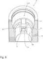
- Fig. 9 a section of a second embodiment of a print model 18 with a cavity 19 is shown.
- the cavity 19 is formed as a bore 20 with an inner wall 21.
- the outer boundary of the print model 18 has been shown around. It is understood that Fig. 9 only a section of the print model 18 shows.
- the bore 20 has six bearing surfaces 26, two of which are arranged in a plane, preferably parallel to the longitudinal direction of the bore 20th
- the projection 27 has a flat front surface 30, the surface normal is preferably aligned perpendicular to the longitudinal axis of the bore 20.
- the front surface 30 is bent.
- a bottom 31 of the projection 27 is formed in the circumferential direction of the bore 20 as a flat and in the radial direction of the bore 20 as a curved surface, wherein the curved surface profile is modeled on the course of the lateral surfaces 13 of the bead 11.
- the underside 31 thus extends transversely to the longitudinal axis along a straight line and is bent in the radial direction of the bore 20. In other words, the underside 31 is straight in one dimension and curved in the other dimension.
- the projection can be engaged behind by a bead 11 of the laboratory analog 1 in the insertion direction such that the lateral surface 13 of the bead 11 (cf. Fig. 8 ) comes into abutment on the underside 31 of the projection 27 only in a small area, for example along a straight line.
- the friction during insertion of the laboratory analog in the cavity is also determined by the size of the area in which the lateral surface 13 of the bead 11 rests against the underside of the projection 27. The smaller this range is, the less friction occurs when using the laboratory analog. Comes the lateral surface along a line on the bottom 31 of the projection 27 to the plant so is the Friction lower than when the lateral surface comes almost fully over the projection 27 to the plant.
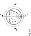
- a second embodiment of the system 22 which comprises the laboratory analog 1 and the print model 18 with the bore 20.
- the sectional pictures of the FIGS. 10b and 10c are rotated by 90 ° to each other, wherein the cutting plane in Fig. 10c Off-center runs.
- centering elements 8 are formed as lateral surfaces 13 of the beads 11.
- the second embodiment of the system 22 further differs in that three beads 11 engage behind the projections 27 of the bore 20, so that three paragraphs 14 of the laboratory analogue 1 come to rest on three shoulders 25 of the bore 20. As a result, the laboratory analog 1 is clamped in the bore 20 in the longitudinal direction.
- Another difference is that instead of two three fixing surfaces 17 of the laboratory analogue 1 abut against six contact surfaces 26 of the bore 20. As a result, the rotational fixation of the laboratory analogue 1 in the bore 20 is ensured. Occurring rotational forces are distributed here on six contact surfaces 26.
Claims (15)
- Analogue de laboratoire destiné à être inséré dans une cavité (19) d'un modèle d'impression (18) et à la réception d'un pilier, comportant
un corps de base (2) essentiellement cylindrique, lequel s'étend le long d'un axe longitudinal (3),
une première section de centrage (4) pour le centrage de l'analogue de laboratoire (1) dans la cavité (19) du modèle d'impression (18), laquelle est adjacente au corps de base (2) dans la direction coronale,
une deuxième section de centrage (5) pour le centrage de l'analogue de laboratoire (1) dans la cavité (19) du modèle d'impression (18), laquelle est adjacente au corps de base (2) dans la direction apicale,
des éléments d'assujettissement (10) pour l'assujettissement de l'analogue de laboratoire (1) dans la direction longitudinale et
au moins un élément de fixation (16) pour la fixation en rotation de l'analogue de laboratoire (1),
dans lequel la première section de centrage (4) comprend une surface de centrage (7) et la deuxième section de centrage (5) comprend au moins un élément de centrage (8), lesquels sont tous deux appropriés et conçus pour élargir radialement la cavité (19) lors de l'insertion de l'analogue de laboratoire (1),
dans lequel un premier élément d'assujettissement (10) se présente sous forme de bourrelet (11) et un deuxième élément d'assujettissement (10) se présente sous forme de palier (14),
dans lequel le bourrelet (11), lorsque l'analogue de laboratoire (1) est inséré, est conçu pour venir se plaquer sur l'arrière d'une saillie (27) dans la cavité (19) dans la direction d'insertion de telle sorte que le palier (14) vienne en appui sur un épaulement (25) dans la cavité (19) et,
dans lequel l'élément de fixation (16) est de forme plate et, lorsque l'analogue de laboratoire (1) est inséré, repose sur le modèle d'impression (18),
caractérisé en ce que
le bourrelet (11) a une surface d'enveloppe (13) arrondie dans la direction d'insertion avec une zone coronale (13a) et une zone apicale (13b) adjacente à celle-ci et
la surface d'enveloppe (13) s'étend asymétriquement dans une section transversale le long de l'axe longitudinal du corps de base,
dans lequel la surface d'enveloppe (13) dans ladite section transversale présente un rayon le long de la zone coronale (13a) autre que le long de la zone apicale (13b). - Analogue de laboratoire selon la revendication 1, caractérisé en ce que la surface d'enveloppe (13) présente un rayon le long de la zone coronale (13a) plus petit que le long de la zone apicale (13b).
- Analogue de laboratoire selon l'une des revendications précédentes, caractérisé en ce que la première section de centrage (4) comprend un biseau de centrage (6) auquel la surface de centrage coronale (7) est adjacente dans la direction coronale, dans lequel la première section de centrage (4) présente un diamètre plus grand en comparaison avec le corps de base (2).
- Analogue de laboratoire selon l'une des revendications précédentes, caractérisé en ce que l'au moins un bourrelet (11) est disposé à l'extrémité apicale (12) de la deuxième section de centrage (5) et s'étend au moins en partie dans la direction périphérique du corps de base (2).
- Analogue de laboratoire selon l'une des revendications précédentes, caractérisé en ce que l'au moins un palier (14) est disposé à l'extrémité apicale (15) du corps de base (2).
- Analogue de laboratoire selon l'une des revendications précédentes, caractérisé en ce que l'analogue de laboratoire (1) comprend deux éléments de centrage (8) opposés l'un à l'autre ou trois éléments de centrage (8) disposés dans la direction périphérique du corps de base (2), lesquels se présentent sous forme de surfaces de centrage apicales (9).
- Analogue de laboratoire selon l'une des revendications précédentes, caractérisé par quatre éléments d'assujettissement (10), dans lequel deux éléments d'assujettissement (10) se présentent sous forme de bourrelets (11) et deux éléments d'assujettissement (10) se présentent sous forme de paliers (14), dans lequel les bourrelets (11) et les paliers (14) sont disposés respectivement à l'opposé les uns des autres.
- Analogue de laboratoire selon la revendication 7, caractérisé en ce que les paliers (14) et les bourrelets (11) sont disposés en décalage mutuel de 90° dans la direction périphérique du corps de base (2).
- Analogue de laboratoire selon l'une des revendications 1 à 6, caractérisé par six éléments d'assujettissement (10), dans lequel trois éléments d'assujettissement (10) se présentent sous forme de bourrelet (11) et trois éléments d'assujettissement (10) se présentent sous forme de palier (14), dans lequel les bourrelets (11) et les paliers (14) sont disposés respectivement de manière répartie régulièrement dans la direction périphérique du corps de base (2).
- Analogue de laboratoire selon les revendications 6 et 7 ou 6 et 9, caractérisé en ce que les surfaces de centrage apicales (9) se présentent sous forme de surfaces d'enveloppe (13) des bourrelets (11).
- Analogue de laboratoire selon l'une des revendications précédentes, caractérisé en ce que les éléments de fixation (16) comprennent deux surfaces de fixation apicales (17) parallèles l'une à l'autre ou trois surfaces de fixation apicales (17) disposées dans la direction périphérique du corps de base (2), lesquelles respectivement sont disposées parallèlement à l'axe longitudinal du corps de base (2) et délimitent les bourrelets (11) sur la périphérie.
- Système comportant un analogue de laboratoire (1) selon l'une des revendications 1 à 11 et un modèle d'impression (18) avec une cavité (19) se présentant essentiellement sous forme de trou (20) pour la réception de l'analogue de laboratoire (1), dans lequel le trou (20) comporte une paroi interne (21), le modèle d'impression avec
une section d'introduction (22) pour l'introduction de l'analogue de laboratoire (1), laquelle s'étend de manière apicale à partir d'une ouverture coronale (23) du trou (20),
un rétrécissement radial (24) pour le centrage de l'analogue de laboratoire (1), lequel est disposé dans la section d'introduction (22),
un épaulement (25) pour la délimitation de la profondeur d'introduction de l'analogue de laboratoire (1), lequel est adjacent à la section d'introduction (22) dans la direction longitudinale du trou (20),
au moins une surface d'appui (26) pour la fixation en rotation de l'analogue de laboratoire (1), laquelle s'étend dans la direction apicale à partir de l'épaulement (25) et,
une saillie (27), laquelle rétrécit radialement le trou (20) et sur l'arrière de laquelle peut venir se plaquer un bourrelet (11) de l'analogue de laboratoire (1) dans la direction d'introduction de telle sorte qu'un palier (14) de l'analogue de laboratoire (1) vienne en appui sur l'épaulement (25). - Système selon la revendication 12, caractérisé en ce que le rétrécissement radial (24) est disposé rotatif dans la section d'introduction (22) du modèle d'impression (18).
- Système selon la revendication 12 ou la revendication 13, caractérisé par quatre, six ou plus de six surfaces d'appui (26) du modèle d'impression (18), dont au moins certaines sont disposées parallèlement les unes aux autres et s'étendent jusqu'à la saillie (27).
- Système selon l'une des revendications 12 à 14, caractérisé en ce que respectivement deux des surfaces d'appui (26) du modèle d'impression (18) sont disposées dans un plan, de préférence parallèlement à la direction longitudinale du trou (20).
Priority Applications (1)
| Application Number | Priority Date | Filing Date | Title |
|---|---|---|---|
| EP16157528.7A EP3067009B1 (fr) | 2015-03-09 | 2016-02-26 | Réplique pour l'insertion dans une cavité d'un modèle d'impression |
Applications Claiming Priority (2)
| Application Number | Priority Date | Filing Date | Title |
|---|---|---|---|
| EP15158227 | 2015-03-09 | ||
| EP16157528.7A EP3067009B1 (fr) | 2015-03-09 | 2016-02-26 | Réplique pour l'insertion dans une cavité d'un modèle d'impression |
Publications (2)
| Publication Number | Publication Date |
|---|---|
| EP3067009A1 EP3067009A1 (fr) | 2016-09-14 |
| EP3067009B1 true EP3067009B1 (fr) | 2018-04-18 |
Family
ID=52684018
Family Applications (1)
| Application Number | Title | Priority Date | Filing Date |
|---|---|---|---|
| EP16157528.7A Active EP3067009B1 (fr) | 2015-03-09 | 2016-02-26 | Réplique pour l'insertion dans une cavité d'un modèle d'impression |
Country Status (4)
| Country | Link |
|---|---|
| US (1) | US10070947B2 (fr) |
| EP (1) | EP3067009B1 (fr) |
| CA (1) | CA2922311C (fr) |
| ES (1) | ES2675036T3 (fr) |
Families Citing this family (6)
| Publication number | Priority date | Publication date | Assignee | Title |
|---|---|---|---|---|
| ES1162258Y (es) * | 2016-07-15 | 2016-10-27 | Mangrane Esteban Xam-Mar | Replica digital de implante dental para modelo dental fabricado con tecnologia aditiva 3d |
| US11273020B2 (en) * | 2017-06-13 | 2022-03-15 | Biomet 3I, Llc | Implant analogs and methods |
| KR102457761B1 (ko) * | 2020-05-14 | 2022-10-24 | 오스템임플란트 주식회사 | 치과용 랩 아날로그 장치를 설치하는 방법 |
| KR102453761B1 (ko) * | 2020-05-14 | 2022-10-14 | 오스템임플란트 주식회사 | 치과용 랩 아날로그 장치 |
| KR102407250B1 (ko) * | 2022-04-11 | 2022-06-13 | (주)덴탈릭스 | 임플란트 3d 프린팅 모형용 랩 아날로그 |
| KR102561679B1 (ko) * | 2022-12-29 | 2023-07-31 | (주)덴탈릭스 | 임플란트 디지털 랩 아날로그용 힐링어버트먼트 |
Family Cites Families (14)
| Publication number | Priority date | Publication date | Assignee | Title |
|---|---|---|---|---|
| US4054995A (en) * | 1976-05-03 | 1977-10-25 | Yoshida Harry Y | Pin with sleeve for making dental prosthesis |
| US5662476A (en) | 1992-06-29 | 1997-09-02 | Nobel Biocare Ab | Prosthetic implant restoration method |
| US5658147A (en) * | 1995-09-19 | 1997-08-19 | Shopvest, Inc. | Working model for prosthodontic preparation of a crown for installation on an implant fixture |
| BR9806802A (pt) | 1997-01-27 | 2000-05-16 | Implant Innovations Inc | Sistema de reforço e crista para uso com implantes dentários |
| US6619958B2 (en) * | 1997-04-09 | 2003-09-16 | Implant Innovations, Inc. | Implant delivery system |
| US6540516B1 (en) * | 1997-05-05 | 2003-04-01 | Atlantis Components, Inc. | Impression coping platform and related methods |
| US8790408B2 (en) * | 2001-08-31 | 2014-07-29 | Leonard Marotta | Accurate analogs for bone graft prostheses using computer generated anatomical models |
| US7018207B2 (en) | 2002-02-22 | 2006-03-28 | Implant Innovations, Inc. | Dental implant analog having retention groove for soft tissue modeling |
| US7204692B2 (en) * | 2002-03-13 | 2007-04-17 | Lifecore Biomedical, Inc. | Impression cap |
| SI2921131T1 (sl) * | 2005-06-30 | 2021-07-30 | Biomet 3I, Llc | Postopek za izdelavo komponent zobnega vsadka |
| US8100692B2 (en) * | 2007-10-19 | 2012-01-24 | Cagenix Incorporated | Dental framework |
| DE102013004175B4 (de) | 2013-03-12 | 2017-01-26 | Bruno Spindler | Implantatanalog und Analoglagerkörper |
| GB2519296A (en) * | 2013-10-15 | 2015-04-22 | Nobel Biocare Services Ag | Dental implant replica |
| US9414898B2 (en) * | 2014-02-18 | 2016-08-16 | Analoyd Ltd. | Dental implants—replicas of customized abutment and implant analogs |
-
2016
- 2016-02-26 EP EP16157528.7A patent/EP3067009B1/fr active Active
- 2016-02-26 ES ES16157528.7T patent/ES2675036T3/es active Active
- 2016-03-01 CA CA2922311A patent/CA2922311C/fr active Active
- 2016-03-07 US US15/063,277 patent/US10070947B2/en active Active
Non-Patent Citations (1)
| Title |
|---|
| None * |
Also Published As
| Publication number | Publication date |
|---|---|
| EP3067009A1 (fr) | 2016-09-14 |
| US10070947B2 (en) | 2018-09-11 |
| CA2922311C (fr) | 2023-04-11 |
| ES2675036T3 (es) | 2018-07-05 |
| CA2922311A1 (fr) | 2016-09-09 |
| US20160262858A1 (en) | 2016-09-15 |
Similar Documents
| Publication | Publication Date | Title |
|---|---|---|
| EP3067009B1 (fr) | Réplique pour l'insertion dans une cavité d'un modèle d'impression | |
| DE102005027184B4 (de) | Modellimplantat für Zahnimplantate | |
| EP3156000B1 (fr) | Implant dentaire, pilier pour implant dentaire et leur combinaison et ensemble d'implants | |
| DE3515819C2 (fr) | ||
| EP0927000A1 (fr) | Implant dentaire intra-osseux individuel bloque en torsion, outil de decoupage et accessoire de positionnement servant a fabriquer cet implant dentaire individuel | |
| DE102012102059B4 (de) | Haltevorrichtung für Abutment-Rohlinge, Set aus Haltevorrichtung und zu bearbeitendem Aufbau, Aufbau-Rohling und Zahnimplantat-Analog | |
| EP1872740B1 (fr) | Agencement pour la fixation d'une prothèse dentaire à une barre mâle | |
| EP2130513A1 (fr) | Dispositif destiné à l'application d'un chapeau de moulage sur un implant dentaire | |
| WO2015090280A1 (fr) | Implant dentaire individuel placé à l'intérieur d'un os | |
| EP2829250A1 (fr) | Implant dentaire, butée, système d'implant et jeu d'implantation | |
| EP2967768B1 (fr) | Analogue d'implant et support d'analogue | |
| WO2019025321A1 (fr) | Pilier prothétique pour tenir une prothèse dentaire sur un implant dentaire et procédé pour la fabrication d'une prothèse dentaire | |
| EP3285681B1 (fr) | Dispositif et procédé pour la fixation de dents prothétiques | |
| EP2724686B1 (fr) | Implant dentaire et système d'implant dentaire | |
| EP2368518A1 (fr) | Transfert pour implant dentaire | |
| EP3215048B1 (fr) | Embase de pilier | |
| EP2762104B1 (fr) | Pilier de transfer | |
| EP0843989B1 (fr) | Système d'implant remplaçant totalement une dent | |
| DE102007026504A1 (de) | Aufnahmeelement für ein Implantat | |
| WO2014170111A1 (fr) | Procédé de fabrication d'un modele de dentition de precision pour la fabrication/l'adaptation d'une prothese dentaire | |
| EP3829483B1 (fr) | Dispositif pour fixer et/ou pour soutenir la fixation d'une prothèse dentaire amovible sur une prothèse dentaire fixe | |
| EP3595573B1 (fr) | Element secondaire pour un implant dentaire et ensemble d'implant dentaire | |
| EP2408392B1 (fr) | Dispositif de liaison pour une prothèse dentaire | |
| DE202010008261U1 (de) | Verbindungselement zum Verbinden eines Suprastrukturmodells mit einem Sockel in einem Dentalmodell | |
| DE4429724C2 (de) | Kiefermodell und Verfahren zu seiner Herstellung |
Legal Events
| Date | Code | Title | Description |
|---|---|---|---|
| PUAI | Public reference made under article 153(3) epc to a published international application that has entered the european phase |
Free format text: ORIGINAL CODE: 0009012 |
|
| AK | Designated contracting states |
Kind code of ref document: A1 Designated state(s): AL AT BE BG CH CY CZ DE DK EE ES FI FR GB GR HR HU IE IS IT LI LT LU LV MC MK MT NL NO PL PT RO RS SE SI SK SM TR |
|
| AX | Request for extension of the european patent |
Extension state: BA ME |
|
| STAA | Information on the status of an ep patent application or granted ep patent |
Free format text: STATUS: REQUEST FOR EXAMINATION WAS MADE |
|
| 17P | Request for examination filed |
Effective date: 20170201 |
|
| RBV | Designated contracting states (corrected) |
Designated state(s): AL AT BE BG CH CY CZ DE DK EE ES FI FR GB GR HR HU IE IS IT LI LT LU LV MC MK MT NL NO PL PT RO RS SE SI SK SM TR |
|
| GRAP | Despatch of communication of intention to grant a patent |
Free format text: ORIGINAL CODE: EPIDOSNIGR1 |
|
| STAA | Information on the status of an ep patent application or granted ep patent |
Free format text: STATUS: GRANT OF PATENT IS INTENDED |
|
| INTG | Intention to grant announced |
Effective date: 20171130 |
|
| RIN1 | Information on inventor provided before grant (corrected) |
Inventor name: FIX, FRANK |
|
| GRAS | Grant fee paid |
Free format text: ORIGINAL CODE: EPIDOSNIGR3 |
|
| GRAA | (expected) grant |
Free format text: ORIGINAL CODE: 0009210 |
|
| STAA | Information on the status of an ep patent application or granted ep patent |
Free format text: STATUS: THE PATENT HAS BEEN GRANTED |
|
| AK | Designated contracting states |
Kind code of ref document: B1 Designated state(s): AL AT BE BG CH CY CZ DE DK EE ES FI FR GB GR HR HU IE IS IT LI LT LU LV MC MK MT NL NO PL PT RO RS SE SI SK SM TR |
|
| REG | Reference to a national code |
Ref country code: GB Ref legal event code: FG4D Free format text: NOT ENGLISH |
|
| REG | Reference to a national code |
Ref country code: CH Ref legal event code: EP |
|
| REG | Reference to a national code |
Ref country code: DE Ref legal event code: R096 Ref document number: 502016000875 Country of ref document: DE |
|
| REG | Reference to a national code |
Ref country code: AT Ref legal event code: REF Ref document number: 989605 Country of ref document: AT Kind code of ref document: T Effective date: 20180515 |
|
| REG | Reference to a national code |
Ref country code: IE Ref legal event code: FG4D Free format text: LANGUAGE OF EP DOCUMENT: GERMAN |
|
| REG | Reference to a national code |
Ref country code: ES Ref legal event code: FG2A Ref document number: 2675036 Country of ref document: ES Kind code of ref document: T3 Effective date: 20180705 |
|
| REG | Reference to a national code |
Ref country code: NL Ref legal event code: MP Effective date: 20180418 |
|
| REG | Reference to a national code |
Ref country code: LT Ref legal event code: MG4D |
|
| PG25 | Lapsed in a contracting state [announced via postgrant information from national office to epo] |
Ref country code: NL Free format text: LAPSE BECAUSE OF FAILURE TO SUBMIT A TRANSLATION OF THE DESCRIPTION OR TO PAY THE FEE WITHIN THE PRESCRIBED TIME-LIMIT Effective date: 20180418 |
|
| PG25 | Lapsed in a contracting state [announced via postgrant information from national office to epo] |
Ref country code: BG Free format text: LAPSE BECAUSE OF FAILURE TO SUBMIT A TRANSLATION OF THE DESCRIPTION OR TO PAY THE FEE WITHIN THE PRESCRIBED TIME-LIMIT Effective date: 20180718 Ref country code: FI Free format text: LAPSE BECAUSE OF FAILURE TO SUBMIT A TRANSLATION OF THE DESCRIPTION OR TO PAY THE FEE WITHIN THE PRESCRIBED TIME-LIMIT Effective date: 20180418 Ref country code: AL Free format text: LAPSE BECAUSE OF FAILURE TO SUBMIT A TRANSLATION OF THE DESCRIPTION OR TO PAY THE FEE WITHIN THE PRESCRIBED TIME-LIMIT Effective date: 20180418 Ref country code: PL Free format text: LAPSE BECAUSE OF FAILURE TO SUBMIT A TRANSLATION OF THE DESCRIPTION OR TO PAY THE FEE WITHIN THE PRESCRIBED TIME-LIMIT Effective date: 20180418 Ref country code: NO Free format text: LAPSE BECAUSE OF FAILURE TO SUBMIT A TRANSLATION OF THE DESCRIPTION OR TO PAY THE FEE WITHIN THE PRESCRIBED TIME-LIMIT Effective date: 20180718 Ref country code: SE Free format text: LAPSE BECAUSE OF FAILURE TO SUBMIT A TRANSLATION OF THE DESCRIPTION OR TO PAY THE FEE WITHIN THE PRESCRIBED TIME-LIMIT Effective date: 20180418 Ref country code: LT Free format text: LAPSE BECAUSE OF FAILURE TO SUBMIT A TRANSLATION OF THE DESCRIPTION OR TO PAY THE FEE WITHIN THE PRESCRIBED TIME-LIMIT Effective date: 20180418 |
|
| PG25 | Lapsed in a contracting state [announced via postgrant information from national office to epo] |
Ref country code: RS Free format text: LAPSE BECAUSE OF FAILURE TO SUBMIT A TRANSLATION OF THE DESCRIPTION OR TO PAY THE FEE WITHIN THE PRESCRIBED TIME-LIMIT Effective date: 20180418 Ref country code: HR Free format text: LAPSE BECAUSE OF FAILURE TO SUBMIT A TRANSLATION OF THE DESCRIPTION OR TO PAY THE FEE WITHIN THE PRESCRIBED TIME-LIMIT Effective date: 20180418 Ref country code: GR Free format text: LAPSE BECAUSE OF FAILURE TO SUBMIT A TRANSLATION OF THE DESCRIPTION OR TO PAY THE FEE WITHIN THE PRESCRIBED TIME-LIMIT Effective date: 20180719 Ref country code: LV Free format text: LAPSE BECAUSE OF FAILURE TO SUBMIT A TRANSLATION OF THE DESCRIPTION OR TO PAY THE FEE WITHIN THE PRESCRIBED TIME-LIMIT Effective date: 20180418 |
|
| REG | Reference to a national code |
Ref country code: DE Ref legal event code: R097 Ref document number: 502016000875 Country of ref document: DE |
|
| PG25 | Lapsed in a contracting state [announced via postgrant information from national office to epo] |
Ref country code: SK Free format text: LAPSE BECAUSE OF FAILURE TO SUBMIT A TRANSLATION OF THE DESCRIPTION OR TO PAY THE FEE WITHIN THE PRESCRIBED TIME-LIMIT Effective date: 20180418 Ref country code: RO Free format text: LAPSE BECAUSE OF FAILURE TO SUBMIT A TRANSLATION OF THE DESCRIPTION OR TO PAY THE FEE WITHIN THE PRESCRIBED TIME-LIMIT Effective date: 20180418 Ref country code: DK Free format text: LAPSE BECAUSE OF FAILURE TO SUBMIT A TRANSLATION OF THE DESCRIPTION OR TO PAY THE FEE WITHIN THE PRESCRIBED TIME-LIMIT Effective date: 20180418 Ref country code: EE Free format text: LAPSE BECAUSE OF FAILURE TO SUBMIT A TRANSLATION OF THE DESCRIPTION OR TO PAY THE FEE WITHIN THE PRESCRIBED TIME-LIMIT Effective date: 20180418 Ref country code: CZ Free format text: LAPSE BECAUSE OF FAILURE TO SUBMIT A TRANSLATION OF THE DESCRIPTION OR TO PAY THE FEE WITHIN THE PRESCRIBED TIME-LIMIT Effective date: 20180418 |
|
| PLBE | No opposition filed within time limit |
Free format text: ORIGINAL CODE: 0009261 |
|
| STAA | Information on the status of an ep patent application or granted ep patent |
Free format text: STATUS: NO OPPOSITION FILED WITHIN TIME LIMIT |
|
| PG25 | Lapsed in a contracting state [announced via postgrant information from national office to epo] |
Ref country code: SM Free format text: LAPSE BECAUSE OF FAILURE TO SUBMIT A TRANSLATION OF THE DESCRIPTION OR TO PAY THE FEE WITHIN THE PRESCRIBED TIME-LIMIT Effective date: 20180418 |
|
| 26N | No opposition filed |
Effective date: 20190121 |
|
| PG25 | Lapsed in a contracting state [announced via postgrant information from national office to epo] |
Ref country code: SI Free format text: LAPSE BECAUSE OF FAILURE TO SUBMIT A TRANSLATION OF THE DESCRIPTION OR TO PAY THE FEE WITHIN THE PRESCRIBED TIME-LIMIT Effective date: 20180418 |
|
| PG25 | Lapsed in a contracting state [announced via postgrant information from national office to epo] |
Ref country code: MC Free format text: LAPSE BECAUSE OF FAILURE TO SUBMIT A TRANSLATION OF THE DESCRIPTION OR TO PAY THE FEE WITHIN THE PRESCRIBED TIME-LIMIT Effective date: 20180418 Ref country code: LU Free format text: LAPSE BECAUSE OF NON-PAYMENT OF DUE FEES Effective date: 20190226 |
|
| REG | Reference to a national code |
Ref country code: BE Ref legal event code: MM Effective date: 20190228 |
|
| REG | Reference to a national code |
Ref country code: IE Ref legal event code: MM4A |
|
| PG25 | Lapsed in a contracting state [announced via postgrant information from national office to epo] |
Ref country code: IE Free format text: LAPSE BECAUSE OF NON-PAYMENT OF DUE FEES Effective date: 20190226 |
|
| PG25 | Lapsed in a contracting state [announced via postgrant information from national office to epo] |
Ref country code: BE Free format text: LAPSE BECAUSE OF NON-PAYMENT OF DUE FEES Effective date: 20190228 |
|
| PG25 | Lapsed in a contracting state [announced via postgrant information from national office to epo] |
Ref country code: TR Free format text: LAPSE BECAUSE OF FAILURE TO SUBMIT A TRANSLATION OF THE DESCRIPTION OR TO PAY THE FEE WITHIN THE PRESCRIBED TIME-LIMIT Effective date: 20180418 |
|
| PG25 | Lapsed in a contracting state [announced via postgrant information from national office to epo] |
Ref country code: PT Free format text: LAPSE BECAUSE OF FAILURE TO SUBMIT A TRANSLATION OF THE DESCRIPTION OR TO PAY THE FEE WITHIN THE PRESCRIBED TIME-LIMIT Effective date: 20180820 Ref country code: MT Free format text: LAPSE BECAUSE OF FAILURE TO SUBMIT A TRANSLATION OF THE DESCRIPTION OR TO PAY THE FEE WITHIN THE PRESCRIBED TIME-LIMIT Effective date: 20180418 |
|
| PG25 | Lapsed in a contracting state [announced via postgrant information from national office to epo] |
Ref country code: CY Free format text: LAPSE BECAUSE OF FAILURE TO SUBMIT A TRANSLATION OF THE DESCRIPTION OR TO PAY THE FEE WITHIN THE PRESCRIBED TIME-LIMIT Effective date: 20180418 |
|
| PG25 | Lapsed in a contracting state [announced via postgrant information from national office to epo] |
Ref country code: IS Free format text: LAPSE BECAUSE OF FAILURE TO SUBMIT A TRANSLATION OF THE DESCRIPTION OR TO PAY THE FEE WITHIN THE PRESCRIBED TIME-LIMIT Effective date: 20180818 |
|
| PG25 | Lapsed in a contracting state [announced via postgrant information from national office to epo] |
Ref country code: HU Free format text: LAPSE BECAUSE OF FAILURE TO SUBMIT A TRANSLATION OF THE DESCRIPTION OR TO PAY THE FEE WITHIN THE PRESCRIBED TIME-LIMIT; INVALID AB INITIO Effective date: 20160226 |
|
| PG25 | Lapsed in a contracting state [announced via postgrant information from national office to epo] |
Ref country code: MK Free format text: LAPSE BECAUSE OF FAILURE TO SUBMIT A TRANSLATION OF THE DESCRIPTION OR TO PAY THE FEE WITHIN THE PRESCRIBED TIME-LIMIT Effective date: 20180418 |
|
| PGFP | Annual fee paid to national office [announced via postgrant information from national office to epo] |
Ref country code: FR Payment date: 20230217 Year of fee payment: 8 Ref country code: ES Payment date: 20230317 Year of fee payment: 8 Ref country code: CH Payment date: 20230307 Year of fee payment: 8 Ref country code: AT Payment date: 20230215 Year of fee payment: 8 |
|
| PGFP | Annual fee paid to national office [announced via postgrant information from national office to epo] |
Ref country code: IT Payment date: 20230228 Year of fee payment: 8 |
|
| P01 | Opt-out of the competence of the unified patent court (upc) registered |
Effective date: 20230524 |
|
| PGFP | Annual fee paid to national office [announced via postgrant information from national office to epo] |
Ref country code: ES Payment date: 20240319 Year of fee payment: 9 |
|
| PGFP | Annual fee paid to national office [announced via postgrant information from national office to epo] |
Ref country code: AT Payment date: 20240216 Year of fee payment: 9 |
|
| PGFP | Annual fee paid to national office [announced via postgrant information from national office to epo] |
Ref country code: DE Payment date: 20240216 Year of fee payment: 9 Ref country code: GB Payment date: 20240222 Year of fee payment: 9 Ref country code: CH Payment date: 20240301 Year of fee payment: 9 |