EP3066876B1 - Systems, apparatus and methods for synchronizing a global time reference for access points over the air - Google Patents
Systems, apparatus and methods for synchronizing a global time reference for access points over the air Download PDFInfo
- Publication number
- EP3066876B1 EP3066876B1 EP14805425.7A EP14805425A EP3066876B1 EP 3066876 B1 EP3066876 B1 EP 3066876B1 EP 14805425 A EP14805425 A EP 14805425A EP 3066876 B1 EP3066876 B1 EP 3066876B1
- Authority
- EP
- European Patent Office
- Prior art keywords
- access point
- global time
- anchor device
- anchor
- message
- Prior art date
- Legal status (The legal status is an assumption and is not a legal conclusion. Google has not performed a legal analysis and makes no representation as to the accuracy of the status listed.)
- Active
Links
Images


Classifications
-
- H—ELECTRICITY
- H04—ELECTRIC COMMUNICATION TECHNIQUE
- H04W—WIRELESS COMMUNICATION NETWORKS
- H04W56/00—Synchronisation arrangements
- H04W56/001—Synchronization between nodes
- H04W56/0015—Synchronization between nodes one node acting as a reference for the others
-
- H—ELECTRICITY
- H04—ELECTRIC COMMUNICATION TECHNIQUE
- H04W—WIRELESS COMMUNICATION NETWORKS
- H04W88/00—Devices specially adapted for wireless communication networks, e.g. terminals, base stations or access point devices
- H04W88/08—Access point devices
-
- H—ELECTRICITY
- H04—ELECTRIC COMMUNICATION TECHNIQUE
- H04W—WIRELESS COMMUNICATION NETWORKS
- H04W56/00—Synchronisation arrangements
- H04W56/001—Synchronization between nodes
-
- H—ELECTRICITY
- H04—ELECTRIC COMMUNICATION TECHNIQUE
- H04W—WIRELESS COMMUNICATION NETWORKS
- H04W88/00—Devices specially adapted for wireless communication networks, e.g. terminals, base stations or access point devices
- H04W88/12—Access point controller devices
Definitions
- Certain aspects of the present disclosure generally relate to wireless communications, and more particularly, to systems, apparatus and methods for synchronizing a global time reference for access points over the air.
- Access points may communicate with one or more wireless devices within an associated basic service set. Such communications are timed according to a timing synchronization function (TSF) in the access point.
- TSF timing synchronization function
- access points do not currently track a global time reference between access points of the same or different BSSs, which may lead to increased interference, decreased efficiency and throughput in wireless networks.
- Publication US-A-2009/122 782 refers to one example of synchronization of wireless nodes. As such, systems, apparatus and methods are needed for synchronizing a global time reference for access points over the air.
- One aspect of the disclosure provides a method for synchronizing a global time of an access point.
- the method comprises receiving a message comprising a global time indication from a second access point, and when the global time indication of the second access point is later than the global time of the access point, updating the global time of the access point to the global time indication from the second access point, updating a timer of the access point by an increment not to exceed a predetermined value selected small enough to ensure that a beacon transmitted by the access point in accordance with a target beacon transmission time is not missed by at least one associated wireless station, and successively updating the timer by the increment until the timer is updated to correspond to the global time indication from the second access point, wherein successively updating the timer of the access point is performed periodically, wherein the timer corresponds to a timing synchronizing function of the access point, and otherwise maintaining the global time of the access point.
- the apparatus comprises means for receiving a message comprising a global time indication from a second access point; and means for, when the global time indication of the second access point is later than the global time of the access point, updating the global time of the apparatus to the global time indication from the second access point, for updating a timer of the apparatus by an increment not to exceed a predetermined value selected small enough to ensure that a beacon transmitted by the access point in accordance with a target beacon transmission time is not missed by at least one associated wireless station, and for successively updating the timer by an increment until the timer is updated to correspond to the global time indication from the second access point, wherein the apparatus is configured to successively update the timer periodically, wherein the timer corresponds to a timing synchronizing function of the access point; and for maintaining the global time of the access point otherwise.
- Another aspect of the disclosure provides a computer program comprising code that, when executed, causes an apparatus to perform the method of claims 1 to 7.
- Wireless network technologies may include various types of wireless local area networks (WLANs).
- WLAN wireless local area networks
- a WLAN may be used to interconnect nearby devices together, employing widely used networking protocols.
- the various aspects described herein may apply to any communication standard, such as Wi-Fi or, more generally, any member of the IEEE 802.11 family of wireless protocols.
- wireless signals may be transmitted according to a high-efficiency 802.11 protocol using orthogonal frequency-division multiplexing (OFDM), direct-sequence spread spectrum (DSSS) communications, a combination of OFDM and DSSS communications, or other schemes.
- OFDM orthogonal frequency-division multiplexing
- DSSS direct-sequence spread spectrum
- Implementations of the high-efficiency 802.11 protocol may be used for Internet access, sensors, metering, smart grid networks, or other wireless applications.
- aspects of certain devices implementing this particular wireless protocol may consume less power than devices implementing other wireless protocols, may be used to transmit wireless signals across short distances, and/or may be able to transmit signals less likely to be blocked by objects, such as humans.
- a WLAN includes various devices which are the components that access the wireless network.
- access points access points
- STAs stations
- an AP serves as a hub or base station for the WLAN and an STA serves as a user of the WLAN.
- a STA may be a laptop computer, a personal digital assistant (PDA), a mobile phone, etc.
- PDA personal digital assistant
- an STA connects to an AP via a Wi-Fi (e.g., IEEE 802.11 protocol such as 802.11ah) compliant wireless link to obtain general connectivity to the Internet or to other wide area networks.
- Wi-Fi e.g., IEEE 802.11 protocol such as 802.11ah
- an STA may also be used as an AP.
- the techniques described herein may be used for various broadband wireless communication systems, including communication systems that are based on an orthogonal multiplexing scheme.
- Examples of such communication systems include Spatial Division Multiple Access (SDMA), Time Division Multiple Access (TDMA), Orthogonal Frequency Division Multiple Access (OFDMA) systems, Single-Carrier Frequency Division Multiple Access (SC-FDMA) systems, and so forth.
- SDMA Spatial Division Multiple Access
- TDMA Time Division Multiple Access
- OFDMA Orthogonal Frequency Division Multiple Access
- SC-FDMA Single-Carrier Frequency Division Multiple Access
- An SDMA system may utilize sufficiently different directions to concurrently transmit data belonging to multiple user terminals.
- a TDMA system may allow multiple user terminals to share the same frequency channel by dividing the transmission signal into different time slots, each time slot being assigned to different user terminal.
- a TDMA system may implement GSM or some other standards known in the art.
- An OFDMA system utilizes orthogonal frequency division multiplexing (OFDM), which is a modulation technique that partitions the overall system bandwidth into multiple orthogonal sub-carriers. These sub-carriers may also be called tones, bins, etc. With OFDM, each sub-carrier may be independently modulated with data.
- An OFDM system may implement IEEE 802.11 or some other standards known in the art.
- An SC-FDMA system may utilize interleaved FDMA (IFDMA) to transmit on sub-carriers that are distributed across the system bandwidth, localized FDMA (LFDMA) to transmit on a block of adjacent sub-carriers, or enhanced FDMA (EFDMA) to transmit on multiple blocks of adjacent sub-carriers.
- IFDMA interleaved FDMA
- LFDMA localized FDMA
- EFDMA enhanced FDMA
- modulation symbols are sent in the frequency domain with OFDM and in the time domain with SC-FDMA.
- a SC-FDMA system may implement
- a wireless node implemented in accordance with the teachings herein may comprise an access point or an access terminal.
- An access point may comprise, be implemented as, or known as a NodeB, Radio Network Controller (“RNC”), eNodeB, Base Station Controller (“BSC”), Base Transceiver Station (“BTS”), Base Station (“BS”), Transceiver Function (“TF”), Radio Router, Radio Transceiver, Basic Service Set (“BSS”), Extended Service Set (“ESS”), Radio Base Station (“RBS”), or some other terminology.
- RNC Radio Network Controller
- BSC Base Station Controller
- BTS Base Transceiver Station
- BS Base Station
- Transceiver Function Transceiver Function
- Radio Router Radio Transceiver
- BSS Basic Service Set
- ESS Extended Service Set
- RBS Radio Base Station
- a station may also comprise, be implemented as, or known as a user terminal, an access terminal ("AT”), a subscriber station, a subscriber unit, a mobile station, a remote station, a remote terminal, a user agent, a user device, user equipment, or some other terminology.
- an access terminal may comprise a cellular telephone, a cordless telephone, a Session Initiation Protocol ("SIP”) phone, a wireless local loop (“WLL”) station, a personal digital assistant (“PDA”), a handheld device having wireless connection capability, or some other suitable processing device connected to a wireless modem.
- SIP Session Initiation Protocol
- WLL wireless local loop
- PDA personal digital assistant
- a phone e.g., a cellular phone or smartphone
- a computer e.g., a laptop
- a portable communication device e.g., a headset
- a portable computing device e.g., a personal data assistant
- an entertainment device e.g., a music or video device, or a satellite radio
- gaming device or system e.g., a gaming console, a global positioning system device, or any other suitable device that is configured to communicate via a wireless medium.
- certain of the devices described herein may implement the 802.11 ah standard, for example.
- Such devices whether used as an STA or AP or other device, may be used for smart metering or in a smart grid network.
- Such devices may provide sensor applications or be used in home automation.
- the devices may instead or in addition be used in a healthcare context, for example for personal healthcare. They may also be used for surveillance, to enable extended-range Internet connectivity (e.g. for use with hotspots), or to implement machine-to-machine communications.
- FIG. 1 illustrates an example of a wireless communication network or system 100 in which aspects of the present disclosure may be employed.
- the wireless communication system 100 may include access points(AP) 104a, 104b, 104c and 104d.
- the AP 104a and the AP 104b may communicate with one another directly.
- the APs 104a and 104b may not communication with one another directly and instead may communicate with one another through a STA 106, for example, which may operate as a relay between the AP 104a and the AP 104b.
- the AP 104d may function as a global time resource, sometimes called an Anchor, for either of the APs 104a and 104b, for example.
- the AP 104c may function as a global time resource, or Anchor, for either of the APs 104a and 104b, for example.
- An access point may comprise, be implemented as, or known as a Node B, Radio Network Controller (RNC), eNodeB, Base Station Controller (BSC), Base Transceiver Station (BTS), Base Station (BS), Transceiver Function (TF), Radio Router, Radio Transceiver, or some other terminology.
- RNC Radio Network Controller
- eNodeB eNodeB
- BSC Base Station Controller
- BTS Base Transceiver Station
- BS Base Station
- Transceiver Function TF
- Radio Router Radio Transceiver
- a station STA may comprise, be implemented as, or known as an access terminal (AT), a subscriber station, a subscriber unit, a mobile station, a remote station, a remote terminal, a user terminal, a user agent, a user device, user equipment (UE), or some other terminology.
- an access terminal may comprise a cellular telephone, a cordless telephone, a Session Initiation Protocol (SIP) phone, a wireless local loop (WLL) station, a personal digital assistant (PDA), a handheld device having wireless connection capability, or some other suitable processing device connected to a wireless modem.
- SIP Session Initiation Protocol
- WLL wireless local loop
- PDA personal digital assistant
- one or more aspects disclosed herein may be incorporated into a phone (e.g., a cellular phone or smartphone), a computer (e.g., a laptop), a portable communication device, a headset, a portable computing device (e.g., a personal data assistant), an entertainment device (e.g., a music or video device, or a satellite radio), a gaming device or system, a wireless sensor device, a global positioning system device, or any other suitable device that is configured to communicate via a wireless medium.
- a phone e.g., a cellular phone or smartphone
- a computer e.g., a laptop
- a portable communication device e.g., a headset
- a portable computing device e.g., a personal data assistant
- an entertainment device e.g., a music or video device, or a satellite radio
- gaming device or system e.g., a gaming device or system
- a wireless sensor device e.g., a global positioning system device,
- a variety of processes and methods may be used for transmissions in the wireless communication system 100 between the APs 104a-104d and the STA 106.
- a communication link that facilitates transmission from the APs 104a-104b to the STA 106 may be referred to as a downlink (DL), and a communication link that facilitates transmission from the STA 106 to one or both of the APs 104a-104b may be referred to as an uplink (UL).
- DL downlink
- UL uplink
- a downlink may be referred to as a forward link or a forward channel
- an uplink may be referred to as a reverse link or a reverse channel.
- the APs 104a-104b may be configured as base stations and provide wireless communication coverage in basic service areas (BSAs) 102a and 102b, respectively. Depending on the technology considered, BSA can sometimes be called coverage area, cell, etc.
- BSA basic service area
- the APs 104a-104b along with the STA 106 may be referred to as a basic service set (BSS). As shown in FIG. 1 , multiple APs may provide different BSAs to the same device. For example, STA 106 may receive service from both AP 104a and AP 104b.
- the present application contemplates a simple and robust AP-to-AP synchronization protocol utilizing a global time reference which is synchronized between access points.
- AP-to-AP coordination would enable improved throughput and efficiency in the associated wireless networks.
- utilizing a global time reference between access points would allow coordination of uplink and downlink transmissions, as well as coordination of channel use to ensure minimizing interference for wireless nodes located at the edges between basic service areas.
- the present application teaches the synchronization of a global time reference between access points over the air without requiring an external time source.
- synchronization of the global time reference between access points may occur within a short time, e.g., a matter of seconds or less.
- FIG. 2 illustrates various components that may be utilized in a wireless device 202 that may be employed within the wireless communication system 100.
- the wireless device 202 is an example of a device that may be configured to implement the various methods described herein.
- the wireless device 202 may comprise the AP 104 or one of the STAs 106.
- the wireless device 202 may include a processor 204 which controls operation of the wireless device 202.
- the processor 204 may also be referred to as a central processing unit (CPU).
- Memory 206 which may include both read-only memory (ROM) and random access memory (RAM), provides instructions and data to the processor 204.
- a portion of the memory 206 may also include non-volatile random access memory (NVRAM).
- the processor 204 typically performs logical and arithmetic operations based on program instructions stored within the memory 206.
- the instructions in the memory 206 may be executable to implement the methods described herein.
- the processor 204 may comprise or be a component of a processing system implemented with one or more processors.
- the one or more processors may be implemented with any combination of general-purpose microprocessors, microcontrollers, digital signal processors (DSPs), field programmable gate array (FPGAs), programmable logic devices (PLDs), controllers, state machines, gated logic, discrete hardware components, dedicated hardware finite state machines, or any other suitable entities that can perform calculations or other manipulations of information.
- the processing system may also include machine-readable media for storing software.
- Software shall be construed broadly to mean any type of instructions, whether referred to as software, firmware, middleware, microcode, hardware description language, or otherwise. Instructions may include code (e.g., in source code format, binary code format, executable code format, or any other suitable format of code). The instructions, when executed by the one or more processors, cause the processing system to perform the various functions described herein.
- the wireless device 202 may also include a housing 208 that may include a transmitter 210 and a receiver 212 to allow transmission and reception of data between the wireless device 202 and a remote location.
- the transmitter 210 and receiver 212 may be combined into a transceiver 214.
- An antenna 216 may be attached to the housing 208 and electrically coupled to the transceiver 214.
- the wireless device 202 may also include (not shown) multiple transmitters, multiple receivers, multiple transceivers, and/or multiple antennas, which may be utilized during MIMO communications, for example.
- the wireless device 202 may also include a signal detector 218 that may be used in an effort to detect and quantify the level of signals received by the transceiver 214.
- the signal detector 218 may detect such signals as total energy, energy per subcarrier per symbol, power spectral density and other signals.
- the wireless device 202 may also include a digital signal processor (DSP) 220 for use in processing signals.
- DSP 220 may be configured to generate a data unit for transmission.
- the data unit may comprise a physical layer data unit (PPDU).
- PPDU physical layer data unit
- the PPDU is referred to as a packet.
- the wireless device 202 may further comprise a user interface 222 in some aspects.
- the user interface 222 may comprise a keypad, a microphone, a speaker, and/or a display.
- the user interface 222 may include any element or component that conveys information to a user of the wireless device 202 and/or receives input from the user.
- the various components of the wireless device 202 may be coupled together by a bus system 226.
- the bus system 226 may include a data bus, for example, as well as a power bus, a control signal bus, and a status signal bus in addition to the data bus.
- a data bus for example, as well as a power bus, a control signal bus, and a status signal bus in addition to the data bus.
- Those of skill in the art will appreciate the components of the wireless device 202 may be coupled together or accept or provide inputs to each other using some other mechanism.
- processor 204 may be used to implement not only the functionality described above with respect to the processor 204, but also to implement the functionality described above with respect to the signal detector 218 and/or the DSP 220. Further, each of the components illustrated in FIG. 2 may be implemented using a plurality of separate elements.
- FIG. 3 is a flow chart of an aspect of an exemplary method for synchronizing a global time of an access point, according to one implementation.
- a primary AP is the AP 104a and the second AP is the AP 104b
- the wireless device 202 shown in FIG. 2 may represent a more detailed view of either of the APs 104a and 104b, as described above.
- one or more of the steps in flowchart 300 may be performed by, or in connection with, a processor, receiver and/or transmitter, such as the processor 204, receiver 212, and/or transmitter 210 of FIG.
- each AP may include an information element in its beacon that includes a field indicating the offset of the timing synchronization function (TSF) with respect to a global time, in addition to a field indicating the actual TSF value.
- Operation block 302 may include an AP, for example the AP 104a, receiving a message comprising a global time indication from a second access point (AP), for example the AP 104b.
- this global time indication may comprise the offset of the TSF with respect to the global time.
- the AP 104a may be configured to determine or calculate the global time based on the TSF value and the offset of the TSF from the global time.
- the offset of the TSF may comprise the global time indication.
- the AP 104a may compare the received global time indication from the second AP (e.g., the AP 104b) with a stored value of its own global time. If the global time indication from the second AP (e.g., the AP 104b) indicates a later time than the stored value of the global time of the AP 104a, the method may move to operation block 306.
- the AP 104a may update the stored value for its global time to the global time indication from the second AP (AP 104b). The method may then move to operation block 308. However, if the global time indication from the second AP (AP 104b) does not indicate a later time than the stored value of the global time of the AP 104a, the AP 104a may not update its stored value for the global time and the method may move to end block 310. Thus, in this implementation, the AP 104a may only update its global time if the global time indication it receives from another AP, for example the AP 104b, is running ahead of the global time of the AP 104a.
- the AP 104a may instead update its global time if the global time indication it receives from another AP, for example the AP 104b, is running behind the global time of the AP 104a.
- the operation block 304 may include the term "earlier" in place of the term "later”.
- the AP 104a may update a timer by an increment not to exceed a predetermined value.
- the timer may be the TSF of the AP 104a. This operation may occur periodically (e.g., and successively), for example every TBTT, until the TSF of the AP 104a has reached a desired or assigned static offset from the global time. The desired or assigned static offset may be based on the MAC address of the AP 104a for example.
- the method may then continue to end block 310.
- the AP 104a may update the TSF each TBTT by an increment selected to be small enough to ensure a maintenance of synchronization between the AP 104a and any STAs with which it is associated.
- the TSF acts as a timer that determines when to transmit beacons.
- stations associated with a particular AP utilize the known value of the TSF to wake up slightly before a beacon is expected. For this reason, radically changing the value of the TSF (as may have been done with the global time in operation block 306) may cause the associated STAs to miss beacons and start searching for the network again, which is undesirable.
- any modification to the TSF be performed in small increments for each cycle of the TSF to ensure that listening STAs do not miss a transmitted beacon from the AP.
- Maintenance of synchronization with associated STAs may be achieved by incrementing the TSF by an amount not to exceed a maximum permitted TSF shift (K) for each target beacon transmission time (TBTT), according to the following equation:
- K maximum permitted TSF shift
- the amount the TSF may be adjusted per TBTT, or per iteration, will be limited to the lesser of the total required TSF adjustment and the maximum permitted TSF shift per TBTT.
- the actual TSF offset from the newly synchronized global time will decrease (or increase depending on whether the global time was re-synchronized to a value greater than or less than its previous value) by K time units each TBTT until the desired T offset between the global time and the APs TSF is reached.
- the global time of the APs may be synchronized to the most reliable and accurate value while avoiding a loss of synchronization with associated STAs, thus maintaining a robust wireless network.
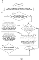
- FIG. 4 is a flow chart of an aspect of an exemplary method for synchronizing a global time of an access point, according to another implementation.
- a primary AP is the AP 104a and the second AP is the AP 104b
- the wireless device 202 shown in FIG. 2 may represent a more detailed view of either of the APs 104a and 104b, as described above.
- one or more of the steps in flowchart 400 may be performed by, or in connection with, a processor and/or transmitter, such as the processor 204 and transmitter 210 of FIG.
- each AP may store at least the following parameters in a memory or register, for example: its own potential anchor metric (PAM), an Anchor weight (PAM of the Anchor), the MAC address of the Anchor, and the last known global time (GT) of the Anchor.
- the AP's own PAM may be an indication of a reliability of that AP's own global time. For example, if a particular AP has a particularly accurate clock, or if the AP has a connection to the internet where it may have access to a particularly accurate clock, that AP may have an increased PAM.
- the Anchor weight is the PAM of the AP currently being utilized by a particular AP as its Anchor.
- the stored Anchor weight may be set to some predetermined value, such as zero.
- the Anchor MAC address is merely the MAC address of the AP ⁇ currently being utilized by a particular AP as its Anchor.
- the last known GT of the Anchor is the global time indication that was most recently received from the Anchor and utilized to calibrate GT by the particular AP.
- beacons transmitted by each AP may include the following: 1) an offset of the AP's TSF from the AP's global time, 2) an Anchor metric, i.e., Anchor weight, associated with the Anchor that the AP has most recently utilized to update its global time, 3) the MAC address of the Anchor, and 4) the last known global time received from the Anchor.
- Anchor metric i.e., Anchor weight
- the method described by flowchart 400 may begin with begin block 402.
- the flowchart 400 may continue to operation block 404, which may include receiving (by the AP 104a) a message (from a second AP e.g., the AP 104b) comprising at least one parameter associated with a second access point.
- the at least one parameter may include an address of an anchor device for the second AP (e.g., the MAC address of the AP 104c), a metric associated with the anchor device (e.g., the anchor metric or anchor weight of the AP 104c), an indication of a global time associated with the second AP (e.g., the AP 104b), and a most recent global time received by the second AP (e.g., the AP 104b) from the anchor device (e.g., the AP 104c).
- an address of an anchor device for the second AP e.g., the MAC address of the AP 104c
- a metric associated with the anchor device e.g., the anchor metric or anchor weight of the AP 104c
- an indication of a global time associated with the second AP e.g., the AP 104b
- a most recent global time received by the second AP e.g., the AP 104b
- the method may continue to operation block 406, where the AP 104a may compare the received MAC address of the Anchor device for the AP 104b (e.g., the MAC address of the AP 104c) to a stored MAC address of its own anchor device (e.g., the AP 104a has stored the MAC address of the Anchor from which it most recently updated its global time indication). If the received MAC address of the Anchor device for the AP 104b matches the stored address of the Anchor device for the AP 104a, the AP 104a may determine that the AP 104b is utilizing the same Anchor (e.g., a common anchor device) for global timing synchronization.
- the AP 104a may compare the received MAC address of the Anchor device for the AP 104b (e.g., the MAC address of the AP 104c) to a stored MAC address of its own anchor device (e.g., the AP 104a has stored the MAC address of the Anchor from which it most recently updated its global
- the AP 104a may also, optionally, compare the received metric with a stored metric of its own Anchor device. This may be a redundant comparison because if the MAC address of the AP 104b is utilizing the same Anchor as the AP 104a, the Anchor metrics would also match. In such a case, the method may continue to operation block 408.
- Operation block 408 may include determining a first length of time since a global time of the second access point (e.g., the AP 104b) was most recently updated.
- the method may determine the first length of time by determining a first difference between the global time associated with the second AP (e.g., the AP 104b) and the most recent global time received by the second AP from the Anchor device (e.g., the AP 104c).
- the method may continue to operation block 410.
- Operation block 410 may include determining a second length of time since the global time of the access point (e.g., the AP 104a) was most recently updated. The method may determine the second length of time by determining a second difference between the stored global time associated with the AP (e.g., the AP 104a) and a stored most recent global time received from the anchor device for the AP. The method may continue to operation block 412.
- the AP 104a may compare the second length to the first length. In other words, the AP 104a may compare the length of time since the AP 104b updated its global time with the length of time since it (the AP 104a) has updated its own global time. If the length of time since the AP 104a last updated its global time is longer than the length of time since the AP 104b last updated its global time, then the global time of the AP 104b has been updated (using a global time reference from the same Anchor) more recently than has the global time of AP 104a.
- the AP 104a can assume that the global time associated with the AP 104b is more accurate than the current global time stored by the AP 104a because it was more recently updated. In such a case, the method may continue to operation block 414. However, if the second difference is not greater than the first difference, the AP 104a can assume that its stored global time is more accurate than that of the AP 104b and the AP 104a will not update its global time and proceeds to end block 418.
- the AP 104a may update its global time to the global time associated with the second AP (e.g., the AP 104b).
- the AP 104a may also update its "last known global time for the anchor" to match the one received from AP 104b.
- the AP 104a may only update its "last known global time for the anchor" if the AP 104a receives a message directly from the anchor. The method may then proceed to operation block 416.
- the AP 104a may update a timer of the AP by an increment not to exceed a predetermined value.
- the timer may be the TSF of the AP 104a. This operation may occur periodically (e.g., successively), for example every TBTT, until the TSF of the AP 104a has reached a desired or assigned static offset from the global time. The desired or assigned static offset may be based on the MAC address of the AP 104a for example.
- the method may then continue to end block 418.
- the AP 104a may update the TSF each TBTT by an increment that will ensure a maintenance of synchronization between the AP 104a and any STAs with which it is associated, as previously described in connection with FIG. 3 and equations 1 and 2.
- the method may continue to operation block 420.
- the AP 104a may compare the Anchor metric received from the second AP (e.g., the Anchor metric or weight of the AP 104c received from the AP 104b) with the stored metric/weight of its own Anchor device (e.g., the Anchor metric of the AP 104d). If the received metric of the second AP's Anchor device is greater than the stored metric for the Anchor device of the AP 104a, then the AP 104a may determine that the Anchor device for the AP 104b is the most reliable device to serve as its Anchor.
- the Anchor metric received from the second AP e.g., the Anchor metric or weight of the AP 104c received from the AP 104b
- the stored metric/weight of its own Anchor device e.g., the Anchor metric of the AP 104d
- the method may continue to operation block 414, where the AP 104a may update its global time to the global time associated with the second AP (e.g., the AP 104b). In this case, because the AP 104a has changed its Anchor, the AP 104a may additionally update its Anchor weight, Anchor MAC address and last known global time of Anchor values to the corresponding values received in the message from the second AP (e.g., the AP 104b). The method may then proceed to operation block 416 and then end block 418 as described above.
- the AP 104a may determine that its current Anchor is more reliable than the Anchor for the AP 104b and will not update its global time. In such a case, the method may continue to end block 418.
- each AP includes the above-mentioned information in each beacon, all APs will eventually synchronize their global time with the same Anchor, having the highest Anchor metric/weight, thereby also synchronizing their global time to that of the most reliable Anchor.
- the APs may synchronize global time with one another based on the above-mentioned information received from other APs. Such information may be communicated through one of two modes for messaging.
- the APs may listen in on beacons transmitted directly from the APs that are in range.
- the beacons transmitted by each AP may include: 1) an offset of the AP's TSF from the AP's global time, 2) an Anchor metric, i.e., Anchor weight, associated with the Anchor that the AP has most recently utilized to update its global time, 3) the MAC address of the Anchor, and 4) the last known global time received from the Anchor.
- the APs may utilize STAs as relays to obtain beacon information of out-of-range APs.
- the APs and STAs may utilize Neighbor report request and response frames to relay the beacon information from one AP to another via at least one STA.
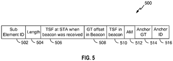
- FIG. 5 illustrates an example of an information element frame for synchronizing a global time reference for access points, according to one implementation.
- FIG. 5 may show a neighborhood report information element (IE) 500 which may be utilized to relay information received by an STA from an OBSS AP to its associated AP .
- IE neighborhood report information element
- the STA 106a may receive a beacon from the AP 104b including the above-mentioned information, and relay that information to the AP 104a utilizing the IE 500.
- the IE 500 may comprise the following fields: a Sub Element ID field 502, a length field 504, a field 506 indicating the TSF at the STA when the beacon was received, a field 508 indicating the offset of the AP's TSF from the AP's global time, a field 510 indicating the AP's TSF received in the beacon, a field 512 indicating the Anchor metric (i.e., the Anchor weight) of the Anchor being utilized by the AP transmitting the beacon, a field 514 indicating the last known global time of the Anchor, and a field 516 indicating the MAC address of the Anchor. Note that if nodes are not using the Anchor method to synchronize, then fields 512, 514 and 516 may not needed. Similarly the beacons themselves may not have any information relating to an anchor.
- the STA 106a may receive a beacon from the AP 104b including an offset of the AP's TSF from the AP's global time, an Anchor metric, i.e., Anchor weight, associated with the Anchor that the AP has most recently utilized to update its global time, the MAC address of the Anchor, and the last known global time received from the Anchor.
- the STA 106a may note its TSF when the beacon was received and populate the value into the field 506. Additionally, the STA may include its TSF counter when the information element gets sent.
- This information may allow the receiving AP, i.e., the AP 104a, to additionally account for any delay between the STA 106a receiving the beacon from the AP 104b and the STA 106a transmitting the IE 500 to the AP 104a.
- the STA 106a may additionally use the received offset of the AP's TSF from the AP's global time and populate the value into the field 508.
- the STA 106a may use the received TSF value of the AP and populate the value into the field 510.
- the STA 106a may use the received Anchor metric, global time and MAC ID associated with the Anchor that the transmitting AP has most recently utilized to update its global time and populate the values into the fields 512, 514 and 516, respectively.
- the STA 106a may then transmit the IE 500 to the AP 104a and the AP 104a may use the information as described above to synchronize its global time.
- a phrase referring to "at least one of' a list of items refers to any combination of those items, including single members.
- "at least one of: a, b, or c " is intended to cover: a, b, c, a-b, a-c, b-c, and a-b-c.
- any suitable means capable of performing the operations such as various hardware and/or software component(s), circuits, and/or module(s).
- any operations illustrated in the Figures may be performed by corresponding functional means capable of performing the operations.
- DSP digital signal processor
- ASIC application specific integrated circuit
- FPGA field programmable gate array signal
- PLD programmable logic device
- a general purpose processor may be a microprocessor, but in the alternative, the processor may be any commercially available processor, controller, microcontroller or state machine.
- a processor may also be implemented as a combination of computing devices, e.g., a combination of a DSP and a microprocessor, a plurality of microprocessors, one or more microprocessors in conjunction with a DSP core, or any other such configuration.
- the functions described may be implemented in hardware, software, firmware, or any combination thereof. If implemented in software, the functions may be stored on or transmitted over as one or more instructions or code on a computer-readable medium.
- Computer-readable media includes both computer storage media and communication media including any medium that facilitates transfer of a computer program from one place to another.
- a storage media may be any available media that can be accessed by a computer.
- such computer-readable media can comprise RAM, ROM, EEPROM, CD-ROM or other optical disk storage, magnetic disk storage or other magnetic storage devices, or any other medium that can be used to carry or store desired program code in the form of instructions or data structures and that can be accessed by a computer.
- any connection is properly termed a computer-readable medium.
- the software is transmitted from a website, server, or other remote source using a coaxial cable, fiber optic cable, twisted pair, digital subscriber line (DSL), or wireless technologies such as infrared, radio, and microwave
- the coaxial cable, fiber optic cable, twisted pair, DSL, or wireless technologies such as infrared, radio, and microwave are included in the definition of medium.
- Disk and disc includes compact disc (CD), laser disc, optical disc, digital versatile disc (DVD), floppy disk and Blu-ray disc where disks usually reproduce data magnetically, while discs reproduce data optically with lasers.
- computer readable medium may comprise non-transitory computer readable medium (e.g., tangible media).
- computer readable medium may comprise transitory computer readable medium (e.g., a signal). Combinations of the above should also be included within the scope of computer-readable media.
- modules and/or other appropriate means for performing the methods and techniques described herein can be downloaded and/or otherwise obtained by a user terminal and/or base station as applicable.
- a user terminal and/or base station can be coupled to a server to facilitate the transfer of means for performing the methods described herein.
- various methods described herein can be provided via storage means (e.g., RAM, ROM, a physical storage medium such as a compact disc (CD) or floppy disk, etc.), such that a user terminal and/or base station can obtain the various methods upon coupling or providing the storage means to the device.
- storage means e.g., RAM, ROM, a physical storage medium such as a compact disc (CD) or floppy disk, etc.
- CD compact disc
- floppy disk etc.
- any other suitable technique for providing the methods and techniques described herein to a device can be utilized.
Landscapes
- Engineering & Computer Science (AREA)
- Computer Networks & Wireless Communication (AREA)
- Signal Processing (AREA)
- Mobile Radio Communication Systems (AREA)
- Synchronisation In Digital Transmission Systems (AREA)
Applications Claiming Priority (3)
| Application Number | Priority Date | Filing Date | Title |
|---|---|---|---|
| US201361902047P | 2013-11-08 | 2013-11-08 | |
| US14/533,894 US9655072B2 (en) | 2013-11-08 | 2014-11-05 | Systems, apparatus and methods for synchronizing a global time reference for access points over the air |
| PCT/US2014/064357 WO2015069902A1 (en) | 2013-11-08 | 2014-11-06 | Systems, apparatus and methods for synchronizing a global time reference for access points over the air |
Publications (2)
| Publication Number | Publication Date |
|---|---|
| EP3066876A1 EP3066876A1 (en) | 2016-09-14 |
| EP3066876B1 true EP3066876B1 (en) | 2020-08-19 |
Family
ID=51999533
Family Applications (1)
| Application Number | Title | Priority Date | Filing Date |
|---|---|---|---|
| EP14805425.7A Active EP3066876B1 (en) | 2013-11-08 | 2014-11-06 | Systems, apparatus and methods for synchronizing a global time reference for access points over the air |
Country Status (6)
| Country | Link |
|---|---|
| US (1) | US9655072B2 (enExample) |
| EP (1) | EP3066876B1 (enExample) |
| JP (1) | JP2016538779A (enExample) |
| KR (1) | KR20160083906A (enExample) |
| CN (1) | CN105706505A (enExample) |
| WO (1) | WO2015069902A1 (enExample) |
Families Citing this family (6)
| Publication number | Priority date | Publication date | Assignee | Title |
|---|---|---|---|---|
| US10397090B2 (en) * | 2016-12-28 | 2019-08-27 | Intel IP Corporation | System and method to implement a wireless sniffer in networks using a dedicated sniffer network |
| US11564188B2 (en) * | 2017-10-17 | 2023-01-24 | Telefonaktiebolaget Lm Ericsson (Publ) | Distributed MIMO synchronization |
| US12075374B2 (en) | 2020-10-27 | 2024-08-27 | Electronics And Telecommunications Research Institute | Method and apparatus for synchronization in wireless communication system |
| CN112600918B (zh) * | 2020-12-10 | 2024-02-02 | 厦门牧云数据技术有限公司 | 一种基于bs架构的工控边缘大数据高效处理方法与系统 |
| US12581434B2 (en) * | 2022-04-11 | 2026-03-17 | Qualcomm Incorporated | Time synchronization over a wireless network for latency-sensitive traffic |
| US20240048531A1 (en) * | 2022-08-08 | 2024-02-08 | Apple Inc. | Obfuscation in privacy beacon |
Family Cites Families (12)
| Publication number | Priority date | Publication date | Assignee | Title |
|---|---|---|---|---|
| US20040202119A1 (en) | 2003-04-10 | 2004-10-14 | Edge Stephen William | Base station synchronization in a wireless network |
| FR2871006B1 (fr) * | 2004-05-28 | 2008-09-12 | Thales Sa | Procede et systeme de synchronisation distribuee |
| KR100735344B1 (ko) * | 2004-08-16 | 2007-07-04 | 삼성전자주식회사 | 통신 시스템에서 기지국들 간의 시간 동기 획득 방법 및 시스템 |
| US8023495B1 (en) | 2005-04-08 | 2011-09-20 | Hewlett-Packard Company | Method and system for WLAN synchronization |
| JP2009049591A (ja) * | 2007-08-16 | 2009-03-05 | Mitsubishi Electric Corp | 移動体通信システム |
| US8374163B2 (en) * | 2007-11-09 | 2013-02-12 | Qualcomm Incorporated | Synchronization of wireless nodes |
| WO2012026935A1 (en) | 2010-08-26 | 2012-03-01 | Thomson Licensing | White space usage for wireless local area network devices |
| EP2761783A4 (en) | 2011-09-30 | 2015-05-20 | Intel Corp | WEAKENING OF OVERLAPPING BASIC SERVICES INTERFERENCE IN INTELLIGENT GOVERNORS |
| US20130156016A1 (en) | 2011-12-15 | 2013-06-20 | Texas Instruments Incorporated | Wireless network systems |
| EP2853104B1 (en) * | 2012-05-23 | 2018-01-10 | Nec Corporation | Method and system for supporting the discovery of synchronized clusters of mobile stations in a wireless communication network |
| CN105009480B (zh) * | 2012-12-27 | 2018-02-02 | Lg电子株式会社 | 在无线lan系统的中继网络中多播/广播的方法和设备 |
| US9510286B2 (en) * | 2013-03-27 | 2016-11-29 | Qualcomm Incorporated | Systems and methods for synchronization within a neighborhood aware network |
-
2014
- 2014-11-05 US US14/533,894 patent/US9655072B2/en not_active Expired - Fee Related
- 2014-11-06 CN CN201480061360.0A patent/CN105706505A/zh active Pending
- 2014-11-06 KR KR1020167014827A patent/KR20160083906A/ko not_active Abandoned
- 2014-11-06 WO PCT/US2014/064357 patent/WO2015069902A1/en not_active Ceased
- 2014-11-06 EP EP14805425.7A patent/EP3066876B1/en active Active
- 2014-11-06 JP JP2016528195A patent/JP2016538779A/ja not_active Ceased
Non-Patent Citations (1)
| Title |
|---|
| None * |
Also Published As
| Publication number | Publication date |
|---|---|
| CN105706505A (zh) | 2016-06-22 |
| WO2015069902A1 (en) | 2015-05-14 |
| JP2016538779A (ja) | 2016-12-08 |
| EP3066876A1 (en) | 2016-09-14 |
| US20150131528A1 (en) | 2015-05-14 |
| US9655072B2 (en) | 2017-05-16 |
| KR20160083906A (ko) | 2016-07-12 |
Similar Documents
| Publication | Publication Date | Title |
|---|---|---|
| JP6769987B2 (ja) | 共有通信媒体上の共存システム同期 | |
| US9451654B2 (en) | Systems and methods for multi-hop relay selection | |
| EP3063897B1 (en) | Methods and apparatus for wireless communication using a mixed format | |
| US9655072B2 (en) | Systems, apparatus and methods for synchronizing a global time reference for access points over the air | |
| EP3243355B1 (en) | Wlan ap-assisted multi-way coexistence | |
| US9301158B2 (en) | Systems and methods for optimization of branch synchronization node determination in a peer-to-peer network | |
| EP3064023B1 (en) | Systems and methods for improved communication efficiency in high efficiency wireless networks | |
| US9398633B2 (en) | Methods and apparatus for low power tracking of network system timing for long paging cycles | |
| US20150223246A1 (en) | Systems and methods for improved communication efficiency in high efficiency wireless networks | |
| EP2926606B1 (en) | Systems and methods for optimization of synchronization message transmission intervals in a peer-to-peer network | |
| US9084141B2 (en) | Systems and methods for grouping nodes to reduce collisions | |
| US20160050627A1 (en) | Methods and apparatus for power efficient access in congested networks | |
| WO2022240320A1 (en) | Method for switching off network cells based on the capability of wireless devices in the network. | |
| US20150296434A1 (en) | Systems, methods and apparatus for optimizing machine to machine device performance by dynamically varying slot cycle index |
Legal Events
| Date | Code | Title | Description |
|---|---|---|---|
| PUAI | Public reference made under article 153(3) epc to a published international application that has entered the european phase |
Free format text: ORIGINAL CODE: 0009012 |
|
| 17P | Request for examination filed |
Effective date: 20160427 |
|
| AK | Designated contracting states |
Kind code of ref document: A1 Designated state(s): AL AT BE BG CH CY CZ DE DK EE ES FI FR GB GR HR HU IE IS IT LI LT LU LV MC MK MT NL NO PL PT RO RS SE SI SK SM TR |
|
| AX | Request for extension of the european patent |
Extension state: BA ME |
|
| DAX | Request for extension of the european patent (deleted) | ||
| STAA | Information on the status of an ep patent application or granted ep patent |
Free format text: STATUS: EXAMINATION IS IN PROGRESS |
|
| 17Q | First examination report despatched |
Effective date: 20180124 |
|
| GRAP | Despatch of communication of intention to grant a patent |
Free format text: ORIGINAL CODE: EPIDOSNIGR1 |
|
| STAA | Information on the status of an ep patent application or granted ep patent |
Free format text: STATUS: GRANT OF PATENT IS INTENDED |
|
| INTG | Intention to grant announced |
Effective date: 20200324 |
|
| GRAS | Grant fee paid |
Free format text: ORIGINAL CODE: EPIDOSNIGR3 |
|
| GRAA | (expected) grant |
Free format text: ORIGINAL CODE: 0009210 |
|
| STAA | Information on the status of an ep patent application or granted ep patent |
Free format text: STATUS: THE PATENT HAS BEEN GRANTED |
|
| AK | Designated contracting states |
Kind code of ref document: B1 Designated state(s): AL AT BE BG CH CY CZ DE DK EE ES FI FR GB GR HR HU IE IS IT LI LT LU LV MC MK MT NL NO PL PT RO RS SE SI SK SM TR |
|
| REG | Reference to a national code |
Ref country code: CH Ref legal event code: EP |
|
| REG | Reference to a national code |
Ref country code: DE Ref legal event code: R096 Ref document number: 602014069213 Country of ref document: DE |
|
| REG | Reference to a national code |
Ref country code: AT Ref legal event code: REF Ref document number: 1305373 Country of ref document: AT Kind code of ref document: T Effective date: 20200915 |
|
| REG | Reference to a national code |
Ref country code: IE Ref legal event code: FG4D |
|
| REG | Reference to a national code |
Ref country code: LT Ref legal event code: MG4D |
|
| REG | Reference to a national code |
Ref country code: NL Ref legal event code: MP Effective date: 20200819 |
|
| PG25 | Lapsed in a contracting state [announced via postgrant information from national office to epo] |
Ref country code: SE Free format text: LAPSE BECAUSE OF FAILURE TO SUBMIT A TRANSLATION OF THE DESCRIPTION OR TO PAY THE FEE WITHIN THE PRESCRIBED TIME-LIMIT Effective date: 20200819 Ref country code: BG Free format text: LAPSE BECAUSE OF FAILURE TO SUBMIT A TRANSLATION OF THE DESCRIPTION OR TO PAY THE FEE WITHIN THE PRESCRIBED TIME-LIMIT Effective date: 20201119 Ref country code: LT Free format text: LAPSE BECAUSE OF FAILURE TO SUBMIT A TRANSLATION OF THE DESCRIPTION OR TO PAY THE FEE WITHIN THE PRESCRIBED TIME-LIMIT Effective date: 20200819 Ref country code: NO Free format text: LAPSE BECAUSE OF FAILURE TO SUBMIT A TRANSLATION OF THE DESCRIPTION OR TO PAY THE FEE WITHIN THE PRESCRIBED TIME-LIMIT Effective date: 20201119 Ref country code: HR Free format text: LAPSE BECAUSE OF FAILURE TO SUBMIT A TRANSLATION OF THE DESCRIPTION OR TO PAY THE FEE WITHIN THE PRESCRIBED TIME-LIMIT Effective date: 20200819 Ref country code: FI Free format text: LAPSE BECAUSE OF FAILURE TO SUBMIT A TRANSLATION OF THE DESCRIPTION OR TO PAY THE FEE WITHIN THE PRESCRIBED TIME-LIMIT Effective date: 20200819 Ref country code: GR Free format text: LAPSE BECAUSE OF FAILURE TO SUBMIT A TRANSLATION OF THE DESCRIPTION OR TO PAY THE FEE WITHIN THE PRESCRIBED TIME-LIMIT Effective date: 20201120 Ref country code: PT Free format text: LAPSE BECAUSE OF FAILURE TO SUBMIT A TRANSLATION OF THE DESCRIPTION OR TO PAY THE FEE WITHIN THE PRESCRIBED TIME-LIMIT Effective date: 20201221 |
|
| PGFP | Annual fee paid to national office [announced via postgrant information from national office to epo] |
Ref country code: DE Payment date: 20200819 Year of fee payment: 7 |
|
| REG | Reference to a national code |
Ref country code: AT Ref legal event code: MK05 Ref document number: 1305373 Country of ref document: AT Kind code of ref document: T Effective date: 20200819 |
|
| PG25 | Lapsed in a contracting state [announced via postgrant information from national office to epo] |
Ref country code: LV Free format text: LAPSE BECAUSE OF FAILURE TO SUBMIT A TRANSLATION OF THE DESCRIPTION OR TO PAY THE FEE WITHIN THE PRESCRIBED TIME-LIMIT Effective date: 20200819 Ref country code: RS Free format text: LAPSE BECAUSE OF FAILURE TO SUBMIT A TRANSLATION OF THE DESCRIPTION OR TO PAY THE FEE WITHIN THE PRESCRIBED TIME-LIMIT Effective date: 20200819 Ref country code: PL Free format text: LAPSE BECAUSE OF FAILURE TO SUBMIT A TRANSLATION OF THE DESCRIPTION OR TO PAY THE FEE WITHIN THE PRESCRIBED TIME-LIMIT Effective date: 20200819 Ref country code: NL Free format text: LAPSE BECAUSE OF FAILURE TO SUBMIT A TRANSLATION OF THE DESCRIPTION OR TO PAY THE FEE WITHIN THE PRESCRIBED TIME-LIMIT Effective date: 20200819 Ref country code: IS Free format text: LAPSE BECAUSE OF FAILURE TO SUBMIT A TRANSLATION OF THE DESCRIPTION OR TO PAY THE FEE WITHIN THE PRESCRIBED TIME-LIMIT Effective date: 20201219 |
|
| PG25 | Lapsed in a contracting state [announced via postgrant information from national office to epo] |
Ref country code: DK Free format text: LAPSE BECAUSE OF FAILURE TO SUBMIT A TRANSLATION OF THE DESCRIPTION OR TO PAY THE FEE WITHIN THE PRESCRIBED TIME-LIMIT Effective date: 20200819 Ref country code: CZ Free format text: LAPSE BECAUSE OF FAILURE TO SUBMIT A TRANSLATION OF THE DESCRIPTION OR TO PAY THE FEE WITHIN THE PRESCRIBED TIME-LIMIT Effective date: 20200819 Ref country code: RO Free format text: LAPSE BECAUSE OF FAILURE TO SUBMIT A TRANSLATION OF THE DESCRIPTION OR TO PAY THE FEE WITHIN THE PRESCRIBED TIME-LIMIT Effective date: 20200819 Ref country code: SM Free format text: LAPSE BECAUSE OF FAILURE TO SUBMIT A TRANSLATION OF THE DESCRIPTION OR TO PAY THE FEE WITHIN THE PRESCRIBED TIME-LIMIT Effective date: 20200819 Ref country code: EE Free format text: LAPSE BECAUSE OF FAILURE TO SUBMIT A TRANSLATION OF THE DESCRIPTION OR TO PAY THE FEE WITHIN THE PRESCRIBED TIME-LIMIT Effective date: 20200819 |
|
| REG | Reference to a national code |
Ref country code: DE Ref legal event code: R097 Ref document number: 602014069213 Country of ref document: DE |
|
| PG25 | Lapsed in a contracting state [announced via postgrant information from national office to epo] |
Ref country code: AT Free format text: LAPSE BECAUSE OF FAILURE TO SUBMIT A TRANSLATION OF THE DESCRIPTION OR TO PAY THE FEE WITHIN THE PRESCRIBED TIME-LIMIT Effective date: 20200819 Ref country code: AL Free format text: LAPSE BECAUSE OF FAILURE TO SUBMIT A TRANSLATION OF THE DESCRIPTION OR TO PAY THE FEE WITHIN THE PRESCRIBED TIME-LIMIT Effective date: 20200819 Ref country code: ES Free format text: LAPSE BECAUSE OF FAILURE TO SUBMIT A TRANSLATION OF THE DESCRIPTION OR TO PAY THE FEE WITHIN THE PRESCRIBED TIME-LIMIT Effective date: 20200819 |
|
| PLBE | No opposition filed within time limit |
Free format text: ORIGINAL CODE: 0009261 |
|
| STAA | Information on the status of an ep patent application or granted ep patent |
Free format text: STATUS: NO OPPOSITION FILED WITHIN TIME LIMIT |
|
| PG25 | Lapsed in a contracting state [announced via postgrant information from national office to epo] |
Ref country code: MC Free format text: LAPSE BECAUSE OF FAILURE TO SUBMIT A TRANSLATION OF THE DESCRIPTION OR TO PAY THE FEE WITHIN THE PRESCRIBED TIME-LIMIT Effective date: 20200819 Ref country code: SK Free format text: LAPSE BECAUSE OF FAILURE TO SUBMIT A TRANSLATION OF THE DESCRIPTION OR TO PAY THE FEE WITHIN THE PRESCRIBED TIME-LIMIT Effective date: 20200819 |
|
| REG | Reference to a national code |
Ref country code: CH Ref legal event code: PL |
|
| 26N | No opposition filed |
Effective date: 20210520 |
|
| PG25 | Lapsed in a contracting state [announced via postgrant information from national office to epo] |
Ref country code: IT Free format text: LAPSE BECAUSE OF FAILURE TO SUBMIT A TRANSLATION OF THE DESCRIPTION OR TO PAY THE FEE WITHIN THE PRESCRIBED TIME-LIMIT Effective date: 20200819 Ref country code: LU Free format text: LAPSE BECAUSE OF NON-PAYMENT OF DUE FEES Effective date: 20201106 |
|
| REG | Reference to a national code |
Ref country code: BE Ref legal event code: MM Effective date: 20201130 |
|
| PG25 | Lapsed in a contracting state [announced via postgrant information from national office to epo] |
Ref country code: CH Free format text: LAPSE BECAUSE OF NON-PAYMENT OF DUE FEES Effective date: 20201130 Ref country code: SI Free format text: LAPSE BECAUSE OF FAILURE TO SUBMIT A TRANSLATION OF THE DESCRIPTION OR TO PAY THE FEE WITHIN THE PRESCRIBED TIME-LIMIT Effective date: 20200819 Ref country code: LI Free format text: LAPSE BECAUSE OF NON-PAYMENT OF DUE FEES Effective date: 20201130 |
|
| PG25 | Lapsed in a contracting state [announced via postgrant information from national office to epo] |
Ref country code: IE Free format text: LAPSE BECAUSE OF NON-PAYMENT OF DUE FEES Effective date: 20201106 |
|
| PG25 | Lapsed in a contracting state [announced via postgrant information from national office to epo] |
Ref country code: TR Free format text: LAPSE BECAUSE OF FAILURE TO SUBMIT A TRANSLATION OF THE DESCRIPTION OR TO PAY THE FEE WITHIN THE PRESCRIBED TIME-LIMIT Effective date: 20200819 Ref country code: MT Free format text: LAPSE BECAUSE OF FAILURE TO SUBMIT A TRANSLATION OF THE DESCRIPTION OR TO PAY THE FEE WITHIN THE PRESCRIBED TIME-LIMIT Effective date: 20200819 Ref country code: CY Free format text: LAPSE BECAUSE OF FAILURE TO SUBMIT A TRANSLATION OF THE DESCRIPTION OR TO PAY THE FEE WITHIN THE PRESCRIBED TIME-LIMIT Effective date: 20200819 |
|
| REG | Reference to a national code |
Ref country code: DE Ref legal event code: R119 Ref document number: 602014069213 Country of ref document: DE |
|
| PG25 | Lapsed in a contracting state [announced via postgrant information from national office to epo] |
Ref country code: MK Free format text: LAPSE BECAUSE OF FAILURE TO SUBMIT A TRANSLATION OF THE DESCRIPTION OR TO PAY THE FEE WITHIN THE PRESCRIBED TIME-LIMIT Effective date: 20200819 |
|
| PG25 | Lapsed in a contracting state [announced via postgrant information from national office to epo] |
Ref country code: BE Free format text: LAPSE BECAUSE OF NON-PAYMENT OF DUE FEES Effective date: 20201130 |
|
| PG25 | Lapsed in a contracting state [announced via postgrant information from national office to epo] |
Ref country code: DE Free format text: LAPSE BECAUSE OF NON-PAYMENT OF DUE FEES Effective date: 20220601 |
|
| PGFP | Annual fee paid to national office [announced via postgrant information from national office to epo] |
Ref country code: GB Payment date: 20251009 Year of fee payment: 12 |
|
| PGFP | Annual fee paid to national office [announced via postgrant information from national office to epo] |
Ref country code: FR Payment date: 20251013 Year of fee payment: 12 |