EP3066751B1 - Adaptive laser joining of stator and rotor laminations - Google Patents
Adaptive laser joining of stator and rotor laminations Download PDFInfo
- Publication number
- EP3066751B1 EP3066751B1 EP14727042.5A EP14727042A EP3066751B1 EP 3066751 B1 EP3066751 B1 EP 3066751B1 EP 14727042 A EP14727042 A EP 14727042A EP 3066751 B1 EP3066751 B1 EP 3066751B1
- Authority
- EP
- European Patent Office
- Prior art keywords
- signal
- sensor
- microcontroller
- individual
- digital
- Prior art date
- Legal status (The legal status is an assumption and is not a legal conclusion. Google has not performed a legal analysis and makes no representation as to the accuracy of the status listed.)
- Not-in-force
Links
Images


Classifications
-
- B—PERFORMING OPERATIONS; TRANSPORTING
- B23—MACHINE TOOLS; METAL-WORKING NOT OTHERWISE PROVIDED FOR
- B23K—SOLDERING OR UNSOLDERING; WELDING; CLADDING OR PLATING BY SOLDERING OR WELDING; CUTTING BY APPLYING HEAT LOCALLY, e.g. FLAME CUTTING; WORKING BY LASER BEAM
- B23K26/00—Working by laser beam, e.g. welding, cutting or boring
- B23K26/02—Positioning or observing the workpiece, e.g. with respect to the point of impact; Aligning, aiming or focusing the laser beam
- B23K26/06—Shaping the laser beam, e.g. by masks or multi-focusing
-
- H—ELECTRICITY
- H02—GENERATION; CONVERSION OR DISTRIBUTION OF ELECTRIC POWER
- H02K—DYNAMO-ELECTRIC MACHINES
- H02K15/00—Processes or apparatus specially adapted for manufacturing, assembling, maintaining or repairing of dynamo-electric machines
- H02K15/02—Processes or apparatus specially adapted for manufacturing, assembling, maintaining or repairing of dynamo-electric machines of stator or rotor bodies
-
- B—PERFORMING OPERATIONS; TRANSPORTING
- B23—MACHINE TOOLS; METAL-WORKING NOT OTHERWISE PROVIDED FOR
- B23K—SOLDERING OR UNSOLDERING; WELDING; CLADDING OR PLATING BY SOLDERING OR WELDING; CUTTING BY APPLYING HEAT LOCALLY, e.g. FLAME CUTTING; WORKING BY LASER BEAM
- B23K26/00—Working by laser beam, e.g. welding, cutting or boring
- B23K26/02—Positioning or observing the workpiece, e.g. with respect to the point of impact; Aligning, aiming or focusing the laser beam
- B23K26/04—Automatically aligning, aiming or focusing the laser beam, e.g. using the back-scattered light
-
- B—PERFORMING OPERATIONS; TRANSPORTING
- B23—MACHINE TOOLS; METAL-WORKING NOT OTHERWISE PROVIDED FOR
- B23K—SOLDERING OR UNSOLDERING; WELDING; CLADDING OR PLATING BY SOLDERING OR WELDING; CUTTING BY APPLYING HEAT LOCALLY, e.g. FLAME CUTTING; WORKING BY LASER BEAM
- B23K2101/00—Articles made by soldering, welding or cutting
- B23K2101/34—Coated articles ; Surface treated articles
-
- B—PERFORMING OPERATIONS; TRANSPORTING
- B23—MACHINE TOOLS; METAL-WORKING NOT OTHERWISE PROVIDED FOR
- B23K—SOLDERING OR UNSOLDERING; WELDING; CLADDING OR PLATING BY SOLDERING OR WELDING; CUTTING BY APPLYING HEAT LOCALLY, e.g. FLAME CUTTING; WORKING BY LASER BEAM
- B23K2101/00—Articles made by soldering, welding or cutting
- B23K2101/36—Electric or electronic devices
Definitions
- the present invention relates to an apparatus and a method of adaptive laser joining of stator and rotor laminations, pertaining to the technical field of laser welding techniques and is utilized for joining together individual thin electrical sheets, or laminas, into compact stator and rotor packages to be used in electric motors.
- stator and rotor laminations into compact packages may be divided into various categories, depending on the particular technology employed.
- interlocks clamps Individual laminations may be integrated into compact packages by making use of the so-called interlocks clamps, as disclosed in e.g. US6223417 , US6018207 , and EP0082537 . It is a disadvantage of interlocks that they affect the electromagnetic properties of the packages and do not perform their task when laminations of low thickness are used. Beside that, the forming of interlocks must be integrated into the blanking process as such, adding to the complexity of the tools used for producing the individual laminas.
- Laminations may be bonded together by using special two-component adhesives, as set forth in WO/2013/135378 and EP1833145 .
- the said process is complex and the packages must be heated above a predetermined temperature.
- Document XP000829680 (COSTE F ET AL: "ADAPTIVE CONTROL OF HIGHTHICKNESS LASER WELDING", WELDING INTERNATIONAL, TAYLOR & FRANCIS, ABINGDON, GB, vol. 13, no. 6, 1 January 1999 (1999-01-01), pages 465-469 ) discloses an apparatus for adaptive laser joining, wherein a vision sensor which determines joint geometry before the interaction zone comprises a vibrating mirror which enables the laser beam to be guided, positioned and oscillated. A sensor places behind the mirror controls its position.
- a process similar to the use of two-component adhesives is the use of electrical sheets coated with a special enamel which bonds together the individual laminations into a compact package when subjected to an elevated temperature and pressure.
- the individual laminas may be joined together by using conventional welding methods, usually by using the laser-TIG process.
- a disadvantage of the said process is represented by the size of the weld seams produced which degrade the electromagnetic properties of the entire package just as interlocks do.
- TIG welding is not applicable for high-alloyed electrical sheets as the elevated percentages of silicon and aluminum in the electrical sheet inhibit bonding.
- welding is also less energy-consuming because the material is only melted in particular locations, in other words, the volume of the molten material is substantially smaller.
- the apparatus for adaptive laser joining of stator and rotor laminations consists of three main sections.
- the first section comprises a sensor 4 observing/supervising the workpiece 1, namely the stator or rotor package, and transmitting an analog/digital signal to a filter 5.
- the workpiece is moved by means of a movable table 2, controlled by a process computer 3.
- the sensor may be any type of sensor capable of touchlessly detecting the individual laminas, which is to say, the gaps separating them, for example a laser sensor, a video camera etc.
- the sensor must be capable of detecting the gaps between the individual laminas, which are typically of the order of magnitude of up to 50 ⁇ m.
- a first stage of sensor detection supervision is carried out using an oscilloscope 6 or a corresponding device, connected to the filter 5.
- the filter 5 ensures that noise is removed from the signal of the sensor 4. Prior to being used, the sensor 4 must be correctly adjusted. The adjustment, which is performed manually, modifies the detection range, thereby removing the greater part of the signal, while enhancing the variation of the signal in the gap region.
- the second section of the apparatus consists of a control unit 10, comprising a first microcontroller 7, a second microcontroller 8, and a relay 9 or a digital-to-analog converter 9a.
- the third section of the apparatus comprises any burst or continuous laser 11 allowing the individual bursts to be controlled or the continuous laser beam to be modulated from the outside, by means of the control unit 10.
- the apparatus utilizes the sensor 4 which transmits the signal through the filter 5 to the first microcontroller 7, where the signal is processed and transmitted, in turn, to the second microcontroller 8, which then provides, via the relay 9 or the digital-to-analog converter 9a, for the correct triggering, delaying, or modulation of the laser beam, so that welding takes place in a precisely defined location.
- the workpiece 1 consists of a plurality of individual laminations, generally between 0.2 and 0.65 mm thick. There is a thin gap between adjacent laminas, its width being generally between 10 and 20 % of the base thickness of the laminas. The gap is detected by means of the sensor 4, which has to be set up correctly. Most important when doing this is to adjust the detection range, having the function of a first filter, on the sensor 4.
- the sensor 4 transmits an analog or digital signal to the filer 5, which takes care of filtering out the higher frequencies.
- the signal is received by the first microcontroller 7 in the control unit 10.
- the microcontroller 7 proceeds to transform the analog signal to digital under certain conditions, defined beforehand and obtained by testing various thicknesses of the individual laminas.
- the threshold and the sampling rate of the signal, as well as the delay following the last signal change, can be set programmatically.
- the microcontroller 7 then sends the digital signal to the microcontroller 8 which delays the original signal.
- the delay is required in order to allow for the correct positioning of the sensor 4 relative to the gap in the workpiece 1, so that the position of the sensor 4 and the position of the gap are aligned, in other words, that the sensor 4 actually detects the correct gap and not one gap before or after the detecting position.
- the said problem arises because the measurements and the triggering of the laser are not performed coaxially in a same device.
- the microcontroller 8 depending on the software loaded thereon, performs an additional task.
- the microcontroller 8 does not further modify the signal and controls the correct triggering of the laser pulses via the relay 9.
- the relay 9 is connected to the triggering system on the laser 11 which actually triggers the individual laser pulses. The pulses cause the metal to melt at the point of impact of the pulse, giving rise to spot welding.
- the microcontroller 8 transforms the digital signal received from the microcontroller 7 into a modulated continuous signal and sends it to the digital-to-analog converter 9a.
- the signal is modulated with previously defined parameters, which are programmatically set and allow for arbitrary modulation shapes.
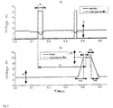
- the adjustable parameters include the following setting: the welding starting point (P1, P2), the welding end point (P2, P4), the delay (D), the lower limit of laser power (A1), and the upper limit of laser power (A2).
- Figure 2 represents the adjustable parameters
- Figure 3 represents some of the possible signal modulation shapes.
- the digital-to-analog converter 9, similarly to the relay 9 acts upon the continuous laser beam, changing it in accordance with the software settings.
- the second microcontroller 8 and the relay 9 or the digital-to-analog converter 9a are connected to the oscilloscope 6 or other device capable of visually displaying the signal.
- the welding procedure is described concretely for a case of stator package welding.
- the workpiece 1, a stator package in this case is fixed to the movable table 2.
- the sensor 4 detects only a full surface.
- a program is launched in the process computer 3, which ensures that the movable table 2 travels with constant speed from one position, starting at the beginning of the fixing device, to the other position, ending at the other end of the stator package 1, namely at the end of the stator package 1.
- the sensor 4 is attached to the apparatus in such a fashion as to detect the gap several tens of milliseconds in advance of the welding position.
- the sensor 4 travels ahead of the welding laser 11 to allow the signal received from the sensor 4 to be processed in the interim.
- the signal travels from the sensor 4 through the filter 5 to the microcontroller 7, where it is converted into a digital signal.
- the digital signal proceeds to the microcontroller 8, where it is conveniently delayed and/or modulated, whereupon the signal passes to the relay 9 or to the digital-to-analog converter 9a which controls the laser.
- the output signal then triggers individual laser pulses, or it modulates the continuous signal.
- the entire cycle is repeated about 10,000 times per second, so that welding can proceed without interruptions as the stator workpiece 1 is being moved.
Landscapes
- Engineering & Computer Science (AREA)
- Physics & Mathematics (AREA)
- Optics & Photonics (AREA)
- Plasma & Fusion (AREA)
- Mechanical Engineering (AREA)
- Manufacturing & Machinery (AREA)
- Power Engineering (AREA)
- Laser Beam Processing (AREA)
- Lining Or Joining Of Plastics Or The Like (AREA)
- Optical Radar Systems And Details Thereof (AREA)
- Lasers (AREA)
Description
- The present invention relates to an apparatus and a method of adaptive laser joining of stator and rotor laminations, pertaining to the technical field of laser welding techniques and is utilized for joining together individual thin electrical sheets, or laminas, into compact stator and rotor packages to be used in electric motors.
- Known methods for joining together stator and rotor laminations into compact packages may be divided into various categories, depending on the particular technology employed.
- Individual laminations may be integrated into compact packages by making use of the so-called interlocks clamps, as disclosed in e.g.
US6223417 ,US6018207 , andEP0082537 . It is a disadvantage of interlocks that they affect the electromagnetic properties of the packages and do not perform their task when laminations of low thickness are used. Beside that, the forming of interlocks must be integrated into the blanking process as such, adding to the complexity of the tools used for producing the individual laminas. - Laminations may be bonded together by using special two-component adhesives, as set forth in
WO/2013/135378 andEP1833145 . The said process is complex and the packages must be heated above a predetermined temperature. - Document XP000829680 (COSTE F ET AL: "ADAPTIVE CONTROL OF HIGHTHICKNESS LASER WELDING", WELDING INTERNATIONAL, TAYLOR & FRANCIS, ABINGDON, GB, vol. 13, no. 6, 1 January 1999 (1999-01-01), pages 465-469) discloses an apparatus for adaptive laser joining, wherein a vision sensor which determines joint geometry before the interaction zone comprises a vibrating mirror which enables the laser beam to be guided, positioned and oscillated. A sensor places behind the mirror controls its position. A process similar to the use of two-component adhesives is the use of electrical sheets coated with a special enamel which bonds together the individual laminations into a compact package when subjected to an elevated temperature and pressure. The details of the said process are disclosed in
WO2006049935 . Although this technique is simpler than the use of two-component adhesives, its main drawback is that the packages must be pressed with a predetermined force and heated to a predetermined temperature for a certain time. - The individual laminas may be joined together by using conventional welding methods, usually by using the laser-TIG process. A disadvantage of the said process is represented by the size of the weld seams produced which degrade the electromagnetic properties of the entire package just as interlocks do. Furthermore, TIG welding is not applicable for high-alloyed electrical sheets as the elevated percentages of silicon and aluminum in the electrical sheet inhibit bonding.
- Nevertheless, the use of laser in both the continuous mode and the burst mode is the best and simplest option for joining individual laminations into compact packages. Laser welding is always started at the beginning and carried on continuously to the end of the package. Welding proceeds transversally across all the laminations. The patents covering this subject are for example
US20130154434 ,JPS5538640 - The technical problem remaining to be adequately solved with respect to prior-art methods and patents is that all the processes used for joining together laminations into stator or rotor packages are cumbersome, like the use of adhesives or enamels; or they affect the electromagnetic properties, like laser or conventional welding or interlocking; or they are not applicable for thinner laminations, like interlocking. While conventional laser joining may be the simplest method, welding is still carried out across the entire lateral surface of the stator or rotor package. Thus an exceeding amount of energy is spent for making additional welds in locations where welding is not needed, furthermore affecting the electromagnetic properties of the stator or rotor package.
- It is an object and aim of the adaptive laser joining of stator and rotor laminations according to the invention to provide an apparatus and a method which will only carry out the joining of individual laminations in the exact location where bonding is required, which is to say, where individual laminations come into contact. There will be no welding in other regions of the lateral surface and this will indirectly contribute to better electromagnetic properties of the stator or rotor package. Thus, welding is also less energy-consuming because the material is only melted in particular locations, in other words, the volume of the molten material is substantially smaller.
- The invention at hand will be described with reference to an embodiment thereof and the accompanying drawings, of which:
-
Figure 1 - represents a schematic diagram of the adaptive laser joining apparatus; -
Figure 2 - represents the program settings; -
Figure 3 - represents some of the possible modulation shapes of the continuous laser beam. - The apparatus for adaptive laser joining of stator and rotor laminations, as illustrated in
Figure 1 , consists of three main sections. The first section comprises asensor 4 observing/supervising theworkpiece 1, namely the stator or rotor package, and transmitting an analog/digital signal to afilter 5. The workpiece is moved by means of a movable table 2, controlled by aprocess computer 3. The sensor may be any type of sensor capable of touchlessly detecting the individual laminas, which is to say, the gaps separating them, for example a laser sensor, a video camera etc. The sensor must be capable of detecting the gaps between the individual laminas, which are typically of the order of magnitude of up to 50 µm. A first stage of sensor detection supervision is carried out using anoscilloscope 6 or a corresponding device, connected to thefilter 5. Thefilter 5 ensures that noise is removed from the signal of thesensor 4. Prior to being used, thesensor 4 must be correctly adjusted. The adjustment, which is performed manually, modifies the detection range, thereby removing the greater part of the signal, while enhancing the variation of the signal in the gap region. The second section of the apparatus consists of acontrol unit 10, comprising afirst microcontroller 7, asecond microcontroller 8, and arelay 9 or a digital-to-analog converter 9a. The third section of the apparatus comprises any burst orcontinuous laser 11 allowing the individual bursts to be controlled or the continuous laser beam to be modulated from the outside, by means of thecontrol unit 10. - So, for detecting the joining point, the apparatus utilizes the
sensor 4 which transmits the signal through thefilter 5 to thefirst microcontroller 7, where the signal is processed and transmitted, in turn, to thesecond microcontroller 8, which then provides, via therelay 9 or the digital-to-analog converter 9a, for the correct triggering, delaying, or modulation of the laser beam, so that welding takes place in a precisely defined location. - The principal phases of the process, which comprise the processing and handling of the individual signals controlling the positioning of the
sensor 4, the proper triggering of the laser bursts or delays or the modulation of the laser beam, are described further below. Theworkpiece 1 consists of a plurality of individual laminations, generally between 0.2 and 0.65 mm thick. There is a thin gap between adjacent laminas, its width being generally between 10 and 20 % of the base thickness of the laminas. The gap is detected by means of thesensor 4, which has to be set up correctly. Most important when doing this is to adjust the detection range, having the function of a first filter, on thesensor 4. Thesensor 4 transmits an analog or digital signal to thefiler 5, which takes care of filtering out the higher frequencies. The signal thus prepared and supervised using anoscilloscope 6 or a similar device allowing for the signal to be displayed visually, is then sent to thecontrol unit 10. The signal is received by thefirst microcontroller 7 in thecontrol unit 10. By virtue of special software themicrocontroller 7 proceeds to transform the analog signal to digital under certain conditions, defined beforehand and obtained by testing various thicknesses of the individual laminas. The threshold and the sampling rate of the signal, as well as the delay following the last signal change, can be set programmatically. Themicrocontroller 7 then sends the digital signal to themicrocontroller 8 which delays the original signal. The delay is required in order to allow for the correct positioning of thesensor 4 relative to the gap in theworkpiece 1, so that the position of thesensor 4 and the position of the gap are aligned, in other words, that thesensor 4 actually detects the correct gap and not one gap before or after the detecting position. The said problem arises because the measurements and the triggering of the laser are not performed coaxially in a same device. - Now, the
microcontroller 8, depending on the software loaded thereon, performs an additional task. In a first variation, used in burst laser applications, themicrocontroller 8 does not further modify the signal and controls the correct triggering of the laser pulses via therelay 9. Therelay 9 is connected to the triggering system on thelaser 11 which actually triggers the individual laser pulses. The pulses cause the metal to melt at the point of impact of the pulse, giving rise to spot welding. - In a second variation, used in continuous laser applications, the
microcontroller 8 transforms the digital signal received from themicrocontroller 7 into a modulated continuous signal and sends it to the digital-to-analog converter 9a. The signal is modulated with previously defined parameters, which are programmatically set and allow for arbitrary modulation shapes. The adjustable parameters include the following setting: the welding starting point (P1, P2), the welding end point (P2, P4), the delay (D), the lower limit of laser power (A1), and the upper limit of laser power (A2).Figure 2 represents the adjustable parameters, whereasFigure 3 represents some of the possible signal modulation shapes. Subsequently, the digital-to-analog converter 9, similarly to therelay 9, acts upon the continuous laser beam, changing it in accordance with the software settings. To allow for additional supervision of the correct overall operation of the system, thesecond microcontroller 8 and therelay 9 or the digital-to-analog converter 9a are connected to theoscilloscope 6 or other device capable of visually displaying the signal. - The welding procedure is described concretely for a case of stator package welding. The
workpiece 1, a stator package in this case, is fixed to the movable table 2. At this time, thesensor 4 detects only a full surface. A program is launched in theprocess computer 3, which ensures that the movable table 2 travels with constant speed from one position, starting at the beginning of the fixing device, to the other position, ending at the other end of thestator package 1, namely at the end of thestator package 1. Given that thestator package 1 is being moved, thesensor 4 is attached to the apparatus in such a fashion as to detect the gap several tens of milliseconds in advance of the welding position. That is to say, thesensor 4 travels ahead of thewelding laser 11 to allow the signal received from thesensor 4 to be processed in the interim. The moment that thesensor 4 detects the gap between laminations on the stator package, the shape of the output signal from thesensor 4 changes. The signal travels from thesensor 4 through thefilter 5 to themicrocontroller 7, where it is converted into a digital signal. The digital signal proceeds to themicrocontroller 8, where it is conveniently delayed and/or modulated, whereupon the signal passes to therelay 9 or to the digital-to-analog converter 9a which controls the laser. The output signal then triggers individual laser pulses, or it modulates the continuous signal. The entire cycle is repeated about 10,000 times per second, so that welding can proceed without interruptions as thestator workpiece 1 is being moved.
Claims (5)
- Method of adaptive laser joining of stator and rotor laminations, wherein laser joining of individual laminations only takes place where two adjacent laminations come into contact, wherein it comprises:- detecting an individual gap between laminations by means of a sensor (4) in real time;- based on the signal from the sensor (4), triggering an individual laser pulse, or- based on the signal from the sensor (4), performing a software-driven modulation of the signal with parameters defined beforehand, and controlling the continuous laser beam by means of the modulated signal;- wherein the detection of an individual gap by means of the sensor (4) in real time comprises adjusting the detection range of the sensor (4), transmitting the signal from the sensor (4) through a filter (5), said filter (5) being used for removal of the noise from the signal of the sensor (4), to a microcontroller (7) in a control unit (10), which transforms the analog signal to digital under certain conditions, defined beforehand and obtained by testing various thicknesses of the individual laminas, sending the digital signal to a microcontroller (8), which delays the original signal in order to allow for the correct positioning of the sensor (4) relative to the gap in the workpiece (1);- the triggering of the individual laser pulses and the controlling of the continuous laser beam, respectively, being controlled by means of the microcontroller (8) in the control unit (10).
- Method according to Claim 1, wherein triggering of individual laser pulses is carried out by means of a relay (9), connected to the triggering system on the laser (11).
- Method according to any preceding claim, wherein the software-driven modulation of the signal is performed via the microcontroller (8) in the control unit (10), which delays the digital signal received from the microcontroller (7) and transforms it into a modulated continuous signal, sending it to the digital-to-analog converter (9a) which controls the continuous laser beam.
- Method according to any preceding claim, wherein adjustment of the detection range of the sensor (4) is performed manually prior to use, by modifying the detection range of the sensor (4) using an oscilloscope (6) or a similar device capable of visually displaying the signal and connected to the filter (5), whereby the greater part of the signal is removed, while the variation of the signal in the gap region is enhanced.
- Apparatus for adaptive laser joining which perform the method according to claims 1 to 4, wherein said apparatus consists of three sections, the first section comprising a sensor (4) which detects the gaps between the individual laminas, the second section consisting of a control unit (10), comprising microcontrollers (7, 8) and the third section comprising a pulse or continuous laser (11) allowing the individual pulses to be controlled and the continuous laser beam to be modulated, respectively, from the outside, by means of the control unit (10), characterized in that the first section further comprises an oscilloscope (6) connected to a filter (5) whereby the oscilloscope (6) is used for carrying out a first stage of sensor (4) detection supervision and the filter (5) is used for removal of the noise from the signal of the sensor (4); the second section further comprises a relay (9) or a digital-to-analog converter (9a) whereby the first microcontroller (7) transforms the analog signal to digital signal and sends the digital signal to the second microcontroller (8) which delays the original signal and controls the correct triggering of the laser pulses via the relay (9) or transforms the digital signal into a modulated continuous signal and sends it to the digital-to-analog converter (9a) which acts upon the continuous laser beam and whereby the second microcontroller (8) and the relay (9) or the digital-to-analog converter (9a) are connected to the oscilloscope (6).
Applications Claiming Priority (2)
| Application Number | Priority Date | Filing Date | Title |
|---|---|---|---|
| SI201300371A SI24532A (en) | 2013-11-05 | 2013-11-05 | Adaptive laser bonding of the stator and rotor laminations |
| PCT/IB2014/000519 WO2015067998A2 (en) | 2013-11-05 | 2014-04-10 | Adaptive laser joining of stator and rotor laminations |
Publications (2)
| Publication Number | Publication Date |
|---|---|
| EP3066751A2 EP3066751A2 (en) | 2016-09-14 |
| EP3066751B1 true EP3066751B1 (en) | 2018-03-07 |
Family
ID=50841890
Family Applications (1)
| Application Number | Title | Priority Date | Filing Date |
|---|---|---|---|
| EP14727042.5A Not-in-force EP3066751B1 (en) | 2013-11-05 | 2014-04-10 | Adaptive laser joining of stator and rotor laminations |
Country Status (7)
| Country | Link |
|---|---|
| US (1) | US20160285350A1 (en) |
| EP (1) | EP3066751B1 (en) |
| CN (1) | CN105980096B (en) |
| MX (1) | MX364966B (en) |
| RU (1) | RU2665856C2 (en) |
| SI (1) | SI24532A (en) |
| WO (1) | WO2015067998A2 (en) |
Families Citing this family (5)
| Publication number | Priority date | Publication date | Assignee | Title |
|---|---|---|---|---|
| DE102016206397A1 (en) | 2016-04-15 | 2017-10-19 | Bühler Motor GmbH | Electronically commutated DC motor with single poles |
| CN110445004B (en) * | 2019-08-07 | 2024-06-25 | 天津凯普林光电科技有限公司 | Optical fiber controller, optical fiber laser and cutting machine |
| CN113909686A (en) * | 2021-09-16 | 2022-01-11 | 中车青岛四方机车车辆股份有限公司 | Laser stitch welding device and method |
| CN114178697B (en) * | 2021-12-20 | 2022-12-13 | 上海交通大学 | Pulse laser micro spot welding system and welding method for motor stator lamination |
| CN116275510B (en) * | 2023-05-17 | 2023-08-25 | 武汉创恒激光智能装备有限公司 | Four-station vision positioning laser welding device and method for silicon steel sheets of motor stator |
Family Cites Families (26)
| Publication number | Priority date | Publication date | Assignee | Title |
|---|---|---|---|---|
| DE3150770A1 (en) | 1981-12-22 | 1983-06-30 | Kienle & Spiess Stanz- und Druckgießwerk GmbH, 7123 Sachsenheim | METHOD FOR PRODUCING PACKAGES CONTAINING SHEET METAL PARTS, AND DEVICE FOR CARRYING OUT SUCH A METHOD |
| US4560856A (en) * | 1982-09-01 | 1985-12-24 | Westinghouse Electric Corp. | Pulsed laser machining apparatus |
| ZA838150B (en) * | 1982-11-01 | 1984-06-27 | Nat Res Dev | Automatic welding |
| US4574176A (en) * | 1983-11-28 | 1986-03-04 | Sws Incorporated | Method and apparatus for pulsed high energy density welding |
| JPS6146389A (en) * | 1984-08-11 | 1986-03-06 | Toyota Motor Corp | Laser welding |
| JPH02220790A (en) * | 1989-02-22 | 1990-09-03 | Fanuc Ltd | Welding method for motor stator |
| GB9321866D0 (en) * | 1993-10-22 | 1993-12-15 | Kinsman Grant | Fuzzy logic control of laser welding |
| US5472772A (en) * | 1994-04-18 | 1995-12-05 | General Electric Company | Method for welding stacker laminations and article therefrom |
| US5932119A (en) * | 1996-01-05 | 1999-08-03 | Lazare Kaplan International, Inc. | Laser marking system |
| US5925268A (en) * | 1996-06-06 | 1999-07-20 | Engauge Inc. | Laser welding apparatus employing a tilting mechanism and seam follower |
| DE19724986C2 (en) * | 1997-06-13 | 1999-07-29 | Jurca Optoelektronik Gmbh | Process for welding workpieces and device for carrying them out |
| CN100392944C (en) * | 1997-10-17 | 2008-06-04 | 精工爱普生株式会社 | Laminated core for motor, method for manufacturing laminated core for motor, and ink jet recording apparatus |
| US6018207A (en) | 1998-07-10 | 2000-01-25 | General Electric Company | Paired interlocks for flexible indexing of rotated stator cores |
| US6223417B1 (en) | 1998-08-19 | 2001-05-01 | General Electric Corporation | Method for forming motor with rotor and stator core paired interlocks |
| US7133182B2 (en) * | 2004-06-07 | 2006-11-07 | Electro Scientific Industries, Inc. | AOM frequency and amplitude modulation techniques for facilitating full beam extinction in laser systems |
| CA2578530C (en) | 2004-10-27 | 2014-04-22 | E. I. Dupont De Nemours And Company | Self-bonding coating composition |
| US7616312B2 (en) * | 2005-06-29 | 2009-11-10 | Dcg Systems, Inc. | Apparatus and method for probing integrated circuits using laser illumination |
| PL1833145T3 (en) | 2006-03-10 | 2012-10-31 | Kienle Spiess Gmbh | Method, tool and device for producing a stack of laminations and stack of laminations |
| JP5353087B2 (en) * | 2008-06-24 | 2013-11-27 | スズキ株式会社 | Laser welding gap control device |
| DE102008041774B4 (en) * | 2008-09-03 | 2026-02-26 | Robert Bosch Gmbh | Device and method for laser welding |
| US8654315B2 (en) * | 2008-10-24 | 2014-02-18 | Prime Photonics, Lc | Differential focus blade clearance probe |
| DE102008055971A1 (en) * | 2008-11-05 | 2010-05-06 | Komet Group Gmbh | Machining center with rotary transformer for electrical energy |
| DE102010013914B4 (en) * | 2010-04-01 | 2013-10-31 | Baden-Württemberg Stiftung Ggmbh | Method for operating a device for processing materials and apparatus |
| CN201985705U (en) * | 2011-03-30 | 2011-09-21 | 方圆集团上海激光科技有限公司 | Laser welding device |
| JP5383781B2 (en) | 2011-12-16 | 2014-01-08 | 三菱電機株式会社 | Stator core, method for manufacturing the same, and rotating electric machine using the stator core |
| DE102012005795A1 (en) | 2012-03-14 | 2013-09-19 | Kienle + Spiess Gmbh | Disc pack and method for its production |
-
2013
- 2013-11-05 SI SI201300371A patent/SI24532A/en not_active IP Right Cessation
-
2014
- 2014-04-10 US US15/034,604 patent/US20160285350A1/en not_active Abandoned
- 2014-04-10 RU RU2016121140A patent/RU2665856C2/en not_active IP Right Cessation
- 2014-04-10 WO PCT/IB2014/000519 patent/WO2015067998A2/en not_active Ceased
- 2014-04-10 EP EP14727042.5A patent/EP3066751B1/en not_active Not-in-force
- 2014-04-10 CN CN201480072385.0A patent/CN105980096B/en not_active Expired - Fee Related
- 2014-04-10 MX MX2016005803A patent/MX364966B/en active IP Right Grant
Also Published As
| Publication number | Publication date |
|---|---|
| MX364966B (en) | 2019-05-15 |
| EP3066751A2 (en) | 2016-09-14 |
| RU2016121140A (en) | 2017-12-07 |
| WO2015067998A2 (en) | 2015-05-14 |
| SI24532A (en) | 2015-05-29 |
| RU2016121140A3 (en) | 2018-03-12 |
| CN105980096B (en) | 2018-01-09 |
| MX2016005803A (en) | 2017-01-16 |
| RU2665856C2 (en) | 2018-09-04 |
| CN105980096A (en) | 2016-09-28 |
| US20160285350A1 (en) | 2016-09-29 |
| WO2015067998A3 (en) | 2015-09-24 |
Similar Documents
| Publication | Publication Date | Title |
|---|---|---|
| US20160285350A1 (en) | Adaptive Laser Joining Of Stator And Rotor Laminations | |
| US9688017B2 (en) | Vibration welders with high frequency vibration, position motion control, and delayed weld motion | |
| EP2455177B1 (en) | Arc welding control method | |
| CN103587114B (en) | A kind of high accuracy hot plate welding device and method | |
| CN105598580A (en) | Laser welding method | |
| CN105834594B (en) | A kind of system and method for application laser cutting and calibration of workpieces | |
| CN105383052A (en) | Ultrasonic press using servo motor with delayed motion | |
| EP2741380B1 (en) | Laser output control device, laser oscillator, and laser output control method | |
| JP2022508117A5 (en) | ||
| EP0143551A1 (en) | Method and apparatus for flash welding | |
| JP2013128974A (en) | Method and apparatus for laser processing by addition of ultrasonic wave | |
| CN207464450U (en) | A kind of automobile sensor welds automatic full inspection MDC systems | |
| JP3821404B2 (en) | Control method of welding robot | |
| JP2004105972A (en) | Laser cutting system | |
| JP5559624B2 (en) | Lap resistance welding method and apparatus | |
| CN104907660A (en) | A PLC-based high frequency brazing machine with a stepping motor and a touch screen and a method for controlling the same | |
| EP2335861A1 (en) | Method and apparatus for joining panels constituting components of motor-vehicle bodies, with quality control through thermographic detection of the entire extension of edges | |
| KR101091171B1 (en) | A control method for a corp shear in continuous hot rolling equipment | |
| US12508670B2 (en) | Welding apparatus and control method for welding apparatus | |
| US20180318964A1 (en) | Cutting module for packaging machine for sachet-type packages made from flexible film | |
| US20230030336A1 (en) | Method and apparatus for welding an aluminum alloy | |
| WO1995018695A1 (en) | Process and plant for joining aluminium parts by soldering, uses of the process and plant for implementing the process | |
| Yamane et al. | Image processing of the weld pool in robotic plasma welding system | |
| YAMANE et al. | In process control of weld pool using weaving control in switch back welding | |
| Wang et al. | Research on Welding Behavior Characterization and Quality Control Methods Based on Multi-Sensor Information Fusion |
Legal Events
| Date | Code | Title | Description |
|---|---|---|---|
| PUAI | Public reference made under article 153(3) epc to a published international application that has entered the european phase |
Free format text: ORIGINAL CODE: 0009012 |
|
| 17P | Request for examination filed |
Effective date: 20160527 |
|
| AK | Designated contracting states |
Kind code of ref document: A2 Designated state(s): AL AT BE BG CH CY CZ DE DK EE ES FI FR GB GR HR HU IE IS IT LI LT LU LV MC MK MT NL NO PL PT RO RS SE SI SK SM TR |
|
| AX | Request for extension of the european patent |
Extension state: BA ME |
|
| DAX | Request for extension of the european patent (deleted) | ||
| RIC1 | Information provided on ipc code assigned before grant |
Ipc: B23K 101/34 20060101ALN20170512BHEP Ipc: B23K 26/06 20140101ALI20170512BHEP Ipc: H02K 15/02 20060101AFI20170512BHEP Ipc: B23K 26/04 20140101ALI20170512BHEP Ipc: B23K 101/36 20060101ALN20170512BHEP |
|
| RIC1 | Information provided on ipc code assigned before grant |
Ipc: B23K 26/04 20140101ALI20170815BHEP Ipc: B23K 101/34 20060101ALN20170815BHEP Ipc: B23K 26/06 20140101ALI20170815BHEP Ipc: B23K 101/36 20060101ALN20170815BHEP Ipc: H02K 15/02 20060101AFI20170815BHEP |
|
| GRAP | Despatch of communication of intention to grant a patent |
Free format text: ORIGINAL CODE: EPIDOSNIGR1 |
|
| INTG | Intention to grant announced |
Effective date: 20171110 |
|
| GRAS | Grant fee paid |
Free format text: ORIGINAL CODE: EPIDOSNIGR3 |
|
| GRAA | (expected) grant |
Free format text: ORIGINAL CODE: 0009210 |
|
| AK | Designated contracting states |
Kind code of ref document: B1 Designated state(s): AL AT BE BG CH CY CZ DE DK EE ES FI FR GB GR HR HU IE IS IT LI LT LU LV MC MK MT NL NO PL PT RO RS SE SI SK SM TR |
|
| RAP1 | Party data changed (applicant data changed or rights of an application transferred) |
Owner name: NELA, RAZVOJNI CENTER ZA ELEKTROINDUSTRIJO IN ELEK |
|
| REG | Reference to a national code |
Ref country code: GB Ref legal event code: FG4D |
|
| REG | Reference to a national code |
Ref country code: CH Ref legal event code: EP Ref country code: AT Ref legal event code: REF Ref document number: 977548 Country of ref document: AT Kind code of ref document: T Effective date: 20180315 |
|
| REG | Reference to a national code |
Ref country code: IE Ref legal event code: FG4D |
|
| REG | Reference to a national code |
Ref country code: DE Ref legal event code: R096 Ref document number: 602014021993 Country of ref document: DE |
|
| REG | Reference to a national code |
Ref country code: FR Ref legal event code: PLFP Year of fee payment: 5 |
|
| REG | Reference to a national code |
Ref country code: NL Ref legal event code: MP Effective date: 20180307 |
|
| REG | Reference to a national code |
Ref country code: LT Ref legal event code: MG4D |
|
| PG25 | Lapsed in a contracting state [announced via postgrant information from national office to epo] |
Ref country code: FI Free format text: LAPSE BECAUSE OF FAILURE TO SUBMIT A TRANSLATION OF THE DESCRIPTION OR TO PAY THE FEE WITHIN THE PRESCRIBED TIME-LIMIT Effective date: 20180307 Ref country code: NO Free format text: LAPSE BECAUSE OF FAILURE TO SUBMIT A TRANSLATION OF THE DESCRIPTION OR TO PAY THE FEE WITHIN THE PRESCRIBED TIME-LIMIT Effective date: 20180607 Ref country code: LT Free format text: LAPSE BECAUSE OF FAILURE TO SUBMIT A TRANSLATION OF THE DESCRIPTION OR TO PAY THE FEE WITHIN THE PRESCRIBED TIME-LIMIT Effective date: 20180307 Ref country code: HR Free format text: LAPSE BECAUSE OF FAILURE TO SUBMIT A TRANSLATION OF THE DESCRIPTION OR TO PAY THE FEE WITHIN THE PRESCRIBED TIME-LIMIT Effective date: 20180307 Ref country code: ES Free format text: LAPSE BECAUSE OF FAILURE TO SUBMIT A TRANSLATION OF THE DESCRIPTION OR TO PAY THE FEE WITHIN THE PRESCRIBED TIME-LIMIT Effective date: 20180307 Ref country code: CY Free format text: LAPSE BECAUSE OF FAILURE TO SUBMIT A TRANSLATION OF THE DESCRIPTION OR TO PAY THE FEE WITHIN THE PRESCRIBED TIME-LIMIT Effective date: 20180307 |
|
| REG | Reference to a national code |
Ref country code: AT Ref legal event code: MK05 Ref document number: 977548 Country of ref document: AT Kind code of ref document: T Effective date: 20180307 |
|
| PG25 | Lapsed in a contracting state [announced via postgrant information from national office to epo] |
Ref country code: RS Free format text: LAPSE BECAUSE OF FAILURE TO SUBMIT A TRANSLATION OF THE DESCRIPTION OR TO PAY THE FEE WITHIN THE PRESCRIBED TIME-LIMIT Effective date: 20180307 Ref country code: SE Free format text: LAPSE BECAUSE OF FAILURE TO SUBMIT A TRANSLATION OF THE DESCRIPTION OR TO PAY THE FEE WITHIN THE PRESCRIBED TIME-LIMIT Effective date: 20180307 Ref country code: LV Free format text: LAPSE BECAUSE OF FAILURE TO SUBMIT A TRANSLATION OF THE DESCRIPTION OR TO PAY THE FEE WITHIN THE PRESCRIBED TIME-LIMIT Effective date: 20180307 Ref country code: GR Free format text: LAPSE BECAUSE OF FAILURE TO SUBMIT A TRANSLATION OF THE DESCRIPTION OR TO PAY THE FEE WITHIN THE PRESCRIBED TIME-LIMIT Effective date: 20180608 Ref country code: BG Free format text: LAPSE BECAUSE OF FAILURE TO SUBMIT A TRANSLATION OF THE DESCRIPTION OR TO PAY THE FEE WITHIN THE PRESCRIBED TIME-LIMIT Effective date: 20180607 |
|
| PG25 | Lapsed in a contracting state [announced via postgrant information from national office to epo] |
Ref country code: NL Free format text: LAPSE BECAUSE OF FAILURE TO SUBMIT A TRANSLATION OF THE DESCRIPTION OR TO PAY THE FEE WITHIN THE PRESCRIBED TIME-LIMIT Effective date: 20180307 Ref country code: PL Free format text: LAPSE BECAUSE OF FAILURE TO SUBMIT A TRANSLATION OF THE DESCRIPTION OR TO PAY THE FEE WITHIN THE PRESCRIBED TIME-LIMIT Effective date: 20180307 Ref country code: EE Free format text: LAPSE BECAUSE OF FAILURE TO SUBMIT A TRANSLATION OF THE DESCRIPTION OR TO PAY THE FEE WITHIN THE PRESCRIBED TIME-LIMIT Effective date: 20180307 Ref country code: AL Free format text: LAPSE BECAUSE OF FAILURE TO SUBMIT A TRANSLATION OF THE DESCRIPTION OR TO PAY THE FEE WITHIN THE PRESCRIBED TIME-LIMIT Effective date: 20180307 Ref country code: RO Free format text: LAPSE BECAUSE OF FAILURE TO SUBMIT A TRANSLATION OF THE DESCRIPTION OR TO PAY THE FEE WITHIN THE PRESCRIBED TIME-LIMIT Effective date: 20180307 |
|
| PG25 | Lapsed in a contracting state [announced via postgrant information from national office to epo] |
Ref country code: CZ Free format text: LAPSE BECAUSE OF FAILURE TO SUBMIT A TRANSLATION OF THE DESCRIPTION OR TO PAY THE FEE WITHIN THE PRESCRIBED TIME-LIMIT Effective date: 20180307 Ref country code: SM Free format text: LAPSE BECAUSE OF FAILURE TO SUBMIT A TRANSLATION OF THE DESCRIPTION OR TO PAY THE FEE WITHIN THE PRESCRIBED TIME-LIMIT Effective date: 20180307 Ref country code: AT Free format text: LAPSE BECAUSE OF FAILURE TO SUBMIT A TRANSLATION OF THE DESCRIPTION OR TO PAY THE FEE WITHIN THE PRESCRIBED TIME-LIMIT Effective date: 20180307 Ref country code: SK Free format text: LAPSE BECAUSE OF FAILURE TO SUBMIT A TRANSLATION OF THE DESCRIPTION OR TO PAY THE FEE WITHIN THE PRESCRIBED TIME-LIMIT Effective date: 20180307 |
|
| REG | Reference to a national code |
Ref country code: DE Ref legal event code: R097 Ref document number: 602014021993 Country of ref document: DE |
|
| REG | Reference to a national code |
Ref country code: BE Ref legal event code: MM Effective date: 20180430 |
|
| PG25 | Lapsed in a contracting state [announced via postgrant information from national office to epo] |
Ref country code: PT Free format text: LAPSE BECAUSE OF FAILURE TO SUBMIT A TRANSLATION OF THE DESCRIPTION OR TO PAY THE FEE WITHIN THE PRESCRIBED TIME-LIMIT Effective date: 20180709 |
|
| PLBE | No opposition filed within time limit |
Free format text: ORIGINAL CODE: 0009261 |
|
| STAA | Information on the status of an ep patent application or granted ep patent |
Free format text: STATUS: NO OPPOSITION FILED WITHIN TIME LIMIT |
|
| REG | Reference to a national code |
Ref country code: IE Ref legal event code: MM4A |
|
| PG25 | Lapsed in a contracting state [announced via postgrant information from national office to epo] |
Ref country code: DK Free format text: LAPSE BECAUSE OF FAILURE TO SUBMIT A TRANSLATION OF THE DESCRIPTION OR TO PAY THE FEE WITHIN THE PRESCRIBED TIME-LIMIT Effective date: 20180307 Ref country code: LU Free format text: LAPSE BECAUSE OF NON-PAYMENT OF DUE FEES Effective date: 20180410 Ref country code: MC Free format text: LAPSE BECAUSE OF FAILURE TO SUBMIT A TRANSLATION OF THE DESCRIPTION OR TO PAY THE FEE WITHIN THE PRESCRIBED TIME-LIMIT Effective date: 20180307 |
|
| 26N | No opposition filed |
Effective date: 20181210 |
|
| GBPC | Gb: european patent ceased through non-payment of renewal fee |
Effective date: 20180607 |
|
| PG25 | Lapsed in a contracting state [announced via postgrant information from national office to epo] |
Ref country code: SI Free format text: LAPSE BECAUSE OF FAILURE TO SUBMIT A TRANSLATION OF THE DESCRIPTION OR TO PAY THE FEE WITHIN THE PRESCRIBED TIME-LIMIT Effective date: 20180307 Ref country code: BE Free format text: LAPSE BECAUSE OF NON-PAYMENT OF DUE FEES Effective date: 20180430 |
|
| PG25 | Lapsed in a contracting state [announced via postgrant information from national office to epo] |
Ref country code: GB Free format text: LAPSE BECAUSE OF NON-PAYMENT OF DUE FEES Effective date: 20180607 Ref country code: IE Free format text: LAPSE BECAUSE OF NON-PAYMENT OF DUE FEES Effective date: 20180410 |
|
| PG25 | Lapsed in a contracting state [announced via postgrant information from national office to epo] |
Ref country code: MT Free format text: LAPSE BECAUSE OF NON-PAYMENT OF DUE FEES Effective date: 20180410 |
|
| PG25 | Lapsed in a contracting state [announced via postgrant information from national office to epo] |
Ref country code: TR Free format text: LAPSE BECAUSE OF FAILURE TO SUBMIT A TRANSLATION OF THE DESCRIPTION OR TO PAY THE FEE WITHIN THE PRESCRIBED TIME-LIMIT Effective date: 20180307 |
|
| PG25 | Lapsed in a contracting state [announced via postgrant information from national office to epo] |
Ref country code: HU Free format text: LAPSE BECAUSE OF FAILURE TO SUBMIT A TRANSLATION OF THE DESCRIPTION OR TO PAY THE FEE WITHIN THE PRESCRIBED TIME-LIMIT; INVALID AB INITIO Effective date: 20140410 Ref country code: MK Free format text: LAPSE BECAUSE OF NON-PAYMENT OF DUE FEES Effective date: 20180307 |
|
| PG25 | Lapsed in a contracting state [announced via postgrant information from national office to epo] |
Ref country code: IS Free format text: LAPSE BECAUSE OF FAILURE TO SUBMIT A TRANSLATION OF THE DESCRIPTION OR TO PAY THE FEE WITHIN THE PRESCRIBED TIME-LIMIT Effective date: 20180707 |
|
| PGFP | Annual fee paid to national office [announced via postgrant information from national office to epo] |
Ref country code: CH Payment date: 20200409 Year of fee payment: 7 Ref country code: FR Payment date: 20200410 Year of fee payment: 7 Ref country code: DE Payment date: 20200407 Year of fee payment: 7 |
|
| PGFP | Annual fee paid to national office [announced via postgrant information from national office to epo] |
Ref country code: IT Payment date: 20200402 Year of fee payment: 7 |
|
| REG | Reference to a national code |
Ref country code: DE Ref legal event code: R119 Ref document number: 602014021993 Country of ref document: DE |
|
| PG25 | Lapsed in a contracting state [announced via postgrant information from national office to epo] |
Ref country code: FR Free format text: LAPSE BECAUSE OF NON-PAYMENT OF DUE FEES Effective date: 20210430 Ref country code: DE Free format text: LAPSE BECAUSE OF NON-PAYMENT OF DUE FEES Effective date: 20211103 Ref country code: CH Free format text: LAPSE BECAUSE OF NON-PAYMENT OF DUE FEES Effective date: 20210430 Ref country code: LI Free format text: LAPSE BECAUSE OF NON-PAYMENT OF DUE FEES Effective date: 20210430 |
|
| PG25 | Lapsed in a contracting state [announced via postgrant information from national office to epo] |
Ref country code: IT Free format text: LAPSE BECAUSE OF NON-PAYMENT OF DUE FEES Effective date: 20200410 |
|
| PG25 | Lapsed in a contracting state [announced via postgrant information from national office to epo] |
Ref country code: IT Free format text: LAPSE BECAUSE OF NON-PAYMENT OF DUE FEES Effective date: 20210410 |