EP3065978B1 - Steering column lock for a steering column for a motor vehicle - Google Patents
Steering column lock for a steering column for a motor vehicle Download PDFInfo
- Publication number
- EP3065978B1 EP3065978B1 EP14795955.5A EP14795955A EP3065978B1 EP 3065978 B1 EP3065978 B1 EP 3065978B1 EP 14795955 A EP14795955 A EP 14795955A EP 3065978 B1 EP3065978 B1 EP 3065978B1
- Authority
- EP
- European Patent Office
- Prior art keywords
- blocking
- locking
- steering wheel
- wheel lock
- slide
- Prior art date
- Legal status (The legal status is an assumption and is not a legal conclusion. Google has not performed a legal analysis and makes no representation as to the accuracy of the status listed.)
- Active
Links
- 230000000903 blocking effect Effects 0.000 claims description 105
- 230000007246 mechanism Effects 0.000 claims description 76
- 238000006073 displacement reaction Methods 0.000 claims description 9
- 230000005540 biological transmission Effects 0.000 description 10
- 230000001154 acute effect Effects 0.000 description 2
- 238000011161 development Methods 0.000 description 2
- 230000018109 developmental process Effects 0.000 description 2
- 230000000694 effects Effects 0.000 description 2
- 230000001960 triggered effect Effects 0.000 description 2
- 230000004308 accommodation Effects 0.000 description 1
- 230000015572 biosynthetic process Effects 0.000 description 1
- 230000003203 everyday effect Effects 0.000 description 1
- 230000004048 modification Effects 0.000 description 1
- 238000012986 modification Methods 0.000 description 1
- 238000002360 preparation method Methods 0.000 description 1
- 238000003466 welding Methods 0.000 description 1
Images


Classifications
-
- B—PERFORMING OPERATIONS; TRANSPORTING
- B60—VEHICLES IN GENERAL
- B60R—VEHICLES, VEHICLE FITTINGS, OR VEHICLE PARTS, NOT OTHERWISE PROVIDED FOR
- B60R25/00—Fittings or systems for preventing or indicating unauthorised use or theft of vehicles
- B60R25/01—Fittings or systems for preventing or indicating unauthorised use or theft of vehicles operating on vehicle systems or fittings, e.g. on doors, seats or windscreens
- B60R25/02—Fittings or systems for preventing or indicating unauthorised use or theft of vehicles operating on vehicle systems or fittings, e.g. on doors, seats or windscreens operating on the steering mechanism
- B60R25/023—Countermeasures against the physical destruction of the steering lock
-
- B—PERFORMING OPERATIONS; TRANSPORTING
- B60—VEHICLES IN GENERAL
- B60R—VEHICLES, VEHICLE FITTINGS, OR VEHICLE PARTS, NOT OTHERWISE PROVIDED FOR
- B60R25/00—Fittings or systems for preventing or indicating unauthorised use or theft of vehicles
- B60R25/01—Fittings or systems for preventing or indicating unauthorised use or theft of vehicles operating on vehicle systems or fittings, e.g. on doors, seats or windscreens
- B60R25/02—Fittings or systems for preventing or indicating unauthorised use or theft of vehicles operating on vehicle systems or fittings, e.g. on doors, seats or windscreens operating on the steering mechanism
- B60R25/021—Fittings or systems for preventing or indicating unauthorised use or theft of vehicles operating on vehicle systems or fittings, e.g. on doors, seats or windscreens operating on the steering mechanism restraining movement of the steering column or steering wheel hub, e.g. restraining means controlled by ignition switch
- B60R25/0211—Fittings or systems for preventing or indicating unauthorised use or theft of vehicles operating on vehicle systems or fittings, e.g. on doors, seats or windscreens operating on the steering mechanism restraining movement of the steering column or steering wheel hub, e.g. restraining means controlled by ignition switch comprising a locking member radially and linearly moved towards the steering column
- B60R25/02115—Fittings or systems for preventing or indicating unauthorised use or theft of vehicles operating on vehicle systems or fittings, e.g. on doors, seats or windscreens operating on the steering mechanism restraining movement of the steering column or steering wheel hub, e.g. restraining means controlled by ignition switch comprising a locking member radially and linearly moved towards the steering column key actuated
-
- B—PERFORMING OPERATIONS; TRANSPORTING
- B60—VEHICLES IN GENERAL
- B60R—VEHICLES, VEHICLE FITTINGS, OR VEHICLE PARTS, NOT OTHERWISE PROVIDED FOR
- B60R25/00—Fittings or systems for preventing or indicating unauthorised use or theft of vehicles
- B60R25/01—Fittings or systems for preventing or indicating unauthorised use or theft of vehicles operating on vehicle systems or fittings, e.g. on doors, seats or windscreens
- B60R25/02—Fittings or systems for preventing or indicating unauthorised use or theft of vehicles operating on vehicle systems or fittings, e.g. on doors, seats or windscreens operating on the steering mechanism
- B60R25/021—Fittings or systems for preventing or indicating unauthorised use or theft of vehicles operating on vehicle systems or fittings, e.g. on doors, seats or windscreens operating on the steering mechanism restraining movement of the steering column or steering wheel hub, e.g. restraining means controlled by ignition switch
- B60R25/0215—Fittings or systems for preventing or indicating unauthorised use or theft of vehicles operating on vehicle systems or fittings, e.g. on doors, seats or windscreens operating on the steering mechanism restraining movement of the steering column or steering wheel hub, e.g. restraining means controlled by ignition switch using electric means, e.g. electric motors or solenoids
- B60R25/02153—Fittings or systems for preventing or indicating unauthorised use or theft of vehicles operating on vehicle systems or fittings, e.g. on doors, seats or windscreens operating on the steering mechanism restraining movement of the steering column or steering wheel hub, e.g. restraining means controlled by ignition switch using electric means, e.g. electric motors or solenoids comprising a locking member radially and linearly moved towards the steering column
Definitions
- the present invention relates to a steering wheel lock for a steering column for a motor vehicle, wherein the steering lock at least one locking bolt which is adjustable between a blocking position for blocking the steering column and at least one release position for releasing the steering column, and a securing mechanism which in a locked state, the blocking bolt in the blocking position is blocked and in an unlocked state allows a movement of the locking bolt in its release position, wherein the securing mechanism comprises at least one by means of a biasing element of the securing mechanism mechanically biased control.
- Generic steering wheel locks have a locking bolt which blocks the steering column when the locking bolt is in the blocking position. In this state, it is not possible to steer the motor vehicle. In the release position, the steering column is not blocked by the blocking bolt, so that a steering of the motor vehicle is possible. It is known to provide appropriate adjustment mechanisms, so that the locking pin can be moved during normal everyday actuation of the steering lock from its blocking position to the release position and vice versa. In abuse, e.g. when the vehicle is to be stolen, it is often attempted to break open the steering lock to move the locking pin out of its blocking position so that the vehicle can be steered. In the prior art, it is already known to provide securing mechanisms which have a locked state by blocking the blocking bolt in the blocking position.
- the unlocked state of the locking mechanism allows this movement of the locking bolt in particular in its release position.
- the safety mechanism should whenever possible automatically go into the locked state, when trying to open the steering wheel lock or break or otherwise manipulated abusive.
- the aim of the safety mechanism or the locked state is to block the locking pin so in the blocking position that can not be steered with the steering column despite up or break or other improper manipulation of the steering lock.
- a generic steering wheel lock with a locking mechanism is for example from the US 2012/0186311 A1 known.
- the securing mechanism on a locking pin, a pivot axis mounted on a pivot lever and a slidably mounted locking pin In the unlocked state of this known in the prior art locking mechanism of the tiltably mounted pivot lever holds the locking pin firmly, as long as the pivot lever is prevented by the pin on a pivoting movement.
- the pin To the Securing mechanism of US 2012/0186311 To bring into its locked state, the pin must be pulled out under the pivot lever.
- the object of the invention is to improve a generic steering wheel lock to the effect that as many different cases of abuse are covered in the simplest possible way.
- control in the unlocked state of the locking mechanism in a normal position in a limited stop surfaces control space of the steering lock on the abutment surfaces and to trigger the blocking state in mutually different ways of displacing or removing at least one of the abutment surfaces of the biasing member with each other different degrees of freedom from the normal position is movable out.
- the securing mechanism has a control which remains so long in a normal position in the bounded by stop surfaces control space of the steering lock, as long as no abuse occurs.
- the control is thus conveniently in normal operation of the steering lock in its normal position and thus ensures the unlocked state of the locking mechanism.
- the unlocked state of the blocking bolt can be adjusted freely by a known adjustment mechanism of the steering lock between its release position and its blocking position.
- the locking pin is usually brought by the adjusting mechanism before the start of the trip in its release position and brought to the shutdown of the vehicle and usually when turning off the ignition from the adjustment back into the blocking position in which the locking pin blocks the steering column and thus steering the vehicle in derogation.
- the steering lock at the same time the ignition of the motor vehicle, by the actuation of the ignition of the vehicle can be switched on and off. Accordingly, the steering lock, as usual, be operated by means of a key. But it is also a different operation of the steering lock or ignition, as is known in the prior art, for example, by pressing a button, possible. The normal operation thus describes the state in which the steering lock is operated following its determination. To distinguish this is the case of abuse, in which it is attempted to break the steering lock or break or otherwise improperly manipulated to bring the locking pin from its blocking position.
- the locking mechanism in its locked state in which the locking pin is blocked in the blocking position, so that it can not be brought into the release position, is provided according to the invention that the control of the biasing member with different degrees of freedom from the Normal position is moved out.
- degree of freedom the number of freely selectable, independent movement possibilities of the control is called.
- the control element preferably has at least two different degrees of freedom, by means of which the securing mechanism can be brought into the blocking state. Conceivable and possible is the formation of three or four degrees of freedom of movement of the control to trigger the blocking state.
- the control element can only be moved out of the normal position by the biasing element with a certain degree of freedom when there is a certain type of displacement or removal of at least one of the abutment surfaces.
- the control element can therefore only be moved out of the normal position with the appropriate degree of freedom if at least one misuse has occurred by at least one of the abutment surfaces being displaced or removed in a specific manner.
- a special feature of the invention lies in the fact that when the at least one of the stop surfaces is displaced or removed in different ways, the biasing element, the control depending on the manner of displacement or removal of the stop surface in different degrees of freedom from the normal position can move out.
- a single stop surface can be displaced or removed in various ways and thereby to achieve a movement of the control element with different degrees of freedom from the normal position out. But it can just as well be provided that when moving or removing mutually different stop surfaces, the biasing member moves the control with different degrees of freedom from the normal position. Regardless of the variants mentioned is always provided that the locking mechanism then goes into the locked state in which it blocks the locking pin in the blocking position when the control is moved out of the biasing member from the normal position.
- This inventive design of the locking mechanism it is possible to intercept different cases of abuse with a single security mechanism or to ensure that the security mechanism passes in different types of abuse action in the locked state.
- different degrees of freedom are different ways and ways of the movement of the control from the normal position out. It may in preferred embodiments e.g. be provided that one of the degrees of freedom is a displacement movement of the control. However, one of the degrees of freedom can just as well be a, preferably axleless, tilting or pivoting movement of the control element. As different degrees of freedom and various sliding movements, various tilting or pivoting movements and / or combinations thereof are possible.
- abutment surfaces in the displacement or removal of the biasing member moves the control from the normal position, it may be a wall portion of a housing or housing part of the steering lock or a removable from a housing or housing part of the steering lock lid of the steering lock.
- at least one of said abutment surfaces is part of a movably mounted support element of the steering lock, wherein the support element, when a lock cylinder is removed from a lock cylinder receiving space of the steering lock, is hineinbewegbar in the lock cylinder receiving space.
- This support member is conveniently biased in the direction of movement into the lock cylinder receiving space.
- different biasing means such as e.g. Leaf or coil springs, elastomeric body and the like in question.
- the biasing element which acts on the control element and all subsequently mentioned biasing means.
- another aspect of the invention relates to a steering wheel lock for a steering column for a motor vehicle, wherein the steering lock at least one locking pin which is adjustable between a blocking position for blocking the steering column and at least one release position for releasing the steering column, and a securing mechanism, which blocks the blocking bolt in the blocking position in a blocking state and permits the blocking bolt to move into its release position in an unlocking state, wherein the securing mechanism has a locking slide biased and displaceably mounted in the direction towards a locking position for blocking the blocking bolt in the blocking position.
- This subsequently described aspect of the invention can be seen together but also independently of the above-mentioned steering wheel lock according to the invention. Again, this is the US 2012/0186311 A1 to be mentioned as the generic state of the art.
- Object of this second aspect of the invention is to provide an alternative embodiment of the steering lock and the safety mechanism available.
- the object of the invention is achieved by a steering wheel lock according to claim 5.
- the subclaims describe advantageous developments of the invention.
- the securing mechanism additionally comprises a support element on which the locking slide is supported in the unlocked state and which releases the locking slide to achieve the locking position and thus the locking state.
- the support element is designed as a prestressed slidably mounted support slide.
- the locking slide is conveniently supported directly on the support element or support slide. In its locking position, the locking slide conveniently engages directly on the blocking bolt. It can e.g. be provided that the locking slide acts on an inclined surface on the blocking bolt, wherein the inclined surface is angled to a blocking bolt movement path along which the blocking bolt between the blocking position and the release position is movably guided, and angled to a Arretierschieberschisbahn along which the locking slide towards the Locking position is movably guided, is arranged. Preferably, each are acute angles.
- the steering lock has at least two interconnected housing parts, wherein the support member may be slidably mounted as a support slide in one of the housing parts.
- the support element z. B. also be fixed to one of the housing parts or fixed.
- the locking slide is conveniently located in another of the housing parts, as the support element.
- the support element optionally in the form of the support slide, when separating the two housing parts of each other, the locking slide to achieve the locking position and thus the lock state free. In this way, another abuse case can be intercepted, namely that when the housing parts which are connected to one another in normal operation of the steering wheel lock are abusively separated from one another.
- housing parts can in one piece but also multi-part, then just in accordance with each other, for example, by screwing, welding or the like, be executed.
- the steering lock such that instead of at least two separate housing parts which are connected to each other, only a one-piece housing is formed with two housing parts.
- the housing parts can then z. B. are separated at a predetermined breaking point in abuse case. In this case, the same effect is achieved.
- the support slide is supported in the unlocked state of the locking mechanism on the control and is released by the control to trigger the blocking state.
- a blocking bolt movement path along which the blocking bolt is movably guided between the blocking position and the release position is angled relative to a locking slide movement path along which the locking slide is movably guided in the direction of the locking position, and / or a support slide movement path along which the support slide is movably guided, is arranged at an angle to the Arretierschieberièresbahn.
- Angled means in general that two things and in particular the trajectories are not parallel to each other and also do not lie on top of each other. Particularly preferably, the said movement paths are oriented orthogonally to one another.
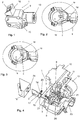
- Fig. 1 the steering wheel lock 1 according to the invention according to the first embodiment is shown in a perspective exterior view.
- the housing parts 9 and 16 which are connected to one another in normal operation and the blocking bolt 2 can be seen.
- the interior in the housing part 9 is accessible via the removable cover 10.
- the lock cylinder accommodating space 13 serves to receive a lock cylinder 12. This is in Fig. 1 however, not disposed in the lock cylinder accommodating space 13.
- a connected to the housing part 16 clamp 18, which serves to receive the steering column is in the Fig. 1 not shown.
- Only the FIGS. 2 and 3 show a representation of the clamp 18 which is connected to the second housing part 16.
- the locking pin 2 is extended in its blocking position.
- this blocking position it engages in a steering spindle, not shown here, of the steering column in order to block it so that it can no longer be rotated about its steering axis and thus a steering of the motor vehicle is prevented.
- a steering spindle not shown here
- the engagement of the steering column or its steering spindle can be done positively, for example, if in the steering column or steering spindle corresponding recesses are provided, in which the locking pin 2 can engage. But it is also a frictional locking or blocking the steering column or its steering spindle possible.
- the steering spindle is in any case the part of the steering column to which a steering wheel is attached.
- the steering column is rotatably mounted about its longitudinal axis and can thus transmit the steering movement of the steering wheel.
- an optional, attached to the housing part 16 clamp 18 is provided. Through the passage opening 19 of the clamp 18, the steering spindle, not shown here, is passed.
- Fig. 3 shows in an otherwise too Fig. 2 analogous representation of the locking pin 2 in its retracted release position in which the steering column is not blocked and the vehicle can be steered.
- Fig. 4 shows the steering lock 1 of this first embodiment in a partially exploded view, in which the housing part 16 shown separated from the housing part 9 and the cover 10 of Housing part 9 is lifted. This allows a view into the interior of the housing part 9 of the steering lock 1.
- the components are illustrated in an exploded view.
- the opening of the interior is just one of the cases of abuse and the device would accordingly go into the locked state, the elements are in Fig. 4 in the interior of the housing part 9 and the elements of the securing mechanism 3 shown in the normal position.
- the transmission shaft 22 is an essential part of the adjustment mechanism.
- the adjustment mechanism is used in normal operation of the motor vehicle to move the locking pin 2 in its blocking position when the vehicle has been turned off and the ignition is issued. If the vehicle is to be restarted, then the adjustment mechanism serves to retract the locking bolt back into its release position, so that the steering column is released and the vehicle can be steered.
- the transmission shaft 22 is rotatably mounted about its longitudinal axis in the housing part 9 and, as is known, with a corresponding axis of rotation of the in Fig. 4 not shown lock cylinder 12 rotatably connected. By turning a key or the like in the lock cylinder 12, the transmission shaft 22 is also rotated.
- the steering lock 1 is used at the same time as the ignition.
- a not shown here, known per se electrical switch exists over the actuation of the ignition of the vehicle can be turned on and off.
- other electrical functions of the vehicle can be switched on and off via this electrical switch.
- the control of the normally occurring in the receiving space 23 electrical switch via the cam 25 of the transmission shaft 22. All this is known per se and need not be further explained.
- the described adjustment mechanism serves, as stated, to actuate the ignition on the one hand and the blocking bolt 2 on the other during normal operation of the vehicle.
- a securing mechanism 3 is present in the steering wheel lock 1 of the embodiments shown here, which serves to block the blocking bolt 2 in its blocking position in abuse cases in which the steering lock 1 is improperly manipulated or broken down or broken.
- the locking mechanism In normal operation, the locking mechanism is in its unlocked state by allowing movement of the locking bolt in its release position by means of the described adjustment mechanism.
- the securing mechanism 3 comprises the control element 5 arranged in the control element 5, the biasing element 4 and the locking slide 14 and the support slide 15 and the biasing means 20 and 21.
- the locking mechanism In normal operation, the locking mechanism is in its unlocked state. This unlock state is also in the section according to Fig. 9 shown by the housing part 9.
- the control 5 In this normal position, the applied by means of the here formed as a helical spring biasing element 4 control 5 is applied to the stop surfaces 6 and 7 and supports the support slide 15 from.
- control element 5 is biased with a coil spring as a biasing means 21 which is supported on the outer wall 24 of the housing part 16 in the direction away from the locking slide 14 with pressure on the control element 5.
- the stop surfaces 6 and 7 limit the control space 8.
- FIG. 5 to 8 is now first of all the blocking bolt 2 together with the securing mechanism 3 and the transmission shaft 22 of the adjusting mechanism but largely without the other components of the steering lock 1 shown.
- the Fig. 5 corresponds with the Fig. 9
- the Fig. 7 corresponds with the Figure 11
- the Fig. 8 corresponds with the Fig. 10
- the FIGS. 5 and 6 are used to illustrate the normal operation, in which the locking pin 2 from the adjustment and thus the steering lock between its release position accordingly Fig. 5 and its blocking position accordingly Fig. 6 can be switched optionally.
- the switching operation is performed by turning a key, not shown here in the lock cylinder also not shown here and the associated rotation of a cam mechanism 26 which is fixed to the transmission shaft 22.
- FIGS. 5 and 6 the locking mechanism is in its unlocked state, in which he has no influence on the locking pin 2 and thus allows movement of the locking pin 2 in its release position.
- the outer wall 24 of the housing part 16 is shown as a dashed line, as for better illustration, the housing part 16 is hidden
- Fig. 5 shows how the locking pin 2 is retracted in normal operation by means of the adjusting mechanism and thus is in its release position in which the motor vehicle steered can be. This corresponds to the position according to Fig. 3
- Fig. 6 is the blocking position according to Fig. 2 illustrated, in which the locking pin 2 is extended by corresponding rotation of the transmission shaft 22.
- the locking mechanism 3 is in its unlocked state, in which he has no influence on the mobility of the locking pin 2.
- FIGS. 7 and 8 now two different cases of abuse are shown in which the locking mechanism 3 is in its locked state.
- the securing mechanism 3 blocks the blocking bolt 2 in the blocking position according to FIG Fig. 2 .
- the blocking bolt 2 then blocks the steering column and the vehicle can no longer be steered, regardless of how and whether the adjustment mechanism and thus the transmission shaft 22 is actuated or not.
- control element 5 in the unlocked state of the locking mechanism 3 in a normal position in a limited by the stop surfaces 6, 7 control chamber 8 of the steering lock 1 against the stop surfaces 6, 7 and to trigger the locking state in mutually different ways of displacing or removing at least one of the stop surfaces 6, 7 from the biasing member 4 with each other different degrees of freedom from the normal position is movable out.
- the control element 5 is moved out of the normal position with different degrees of freedom in different cases of abuse in which at least one stop surface 6 or 7 is displaced or removed in various ways.
- FIGS. 7 and 8 illustrated misuse cases differ from each other, since in them mutually different stop surfaces 6 and 7 are removed or relocated and thus according to the invention, the control 5 is then moved out with different degrees of freedom from the normal position.
- Fig. 7 shows the situation according to Fig. 11 in which the lock cylinder 12 has been broken out of the lock cylinder accommodating space 13.
- Fig. 8 shows the case of abuse according to Fig. 10 in which the cover 10 has been improperly removed from the housing part 9.
- the steering lock 1 is broken by the lid 10 is lifted.
- the stop surfaces 6, which in normal operation according to Fig. 9 limit the control space 8, removed together with the cover 10, whereby this support of the control element 5 is omitted.
- both the locking pin 2 and the locking slide 14 and the support slide 15 are guided exclusively linearly movable.
- the blocking bolt trajectory along which the blocking bolt 2 is movably guided between the blocking position and the release position is angled, in the embodiment shown orthogonally, aligned with the Arretierschieber Gaysbahn along which the locking slide 14 is movably guided in the direction towards the locking position.
- the locking slide 14 acts on the blocking bolt 2 via an inclined surface 17.
- the inclined surface 17 is angled to the blocking pin movement path and also arranged angled to Arretierschieberschisbahn. Preferably, each is an acute angle. This has the consequence that the locking pin 2 is pushed during displacement of the locking slide 14 by means of the biasing means 20 in its locking position in the blocking position, if it is not already completely in the blocking position.
- FIGS. 12 and 13 a third case of abuse is shown with reference to the first embodiment of the steering lock 1.
- the housing parts 9 and 16 which are connected to one another in normal operation, are separated from one another.
- the securing mechanism 3 is brought into its blocking position in this abuse case, since the support slide 15 is slidably mounted in one of the housing parts 9 and the locking slide 14 is slidably mounted in the other of the housing parts 16, so when separating the two housing parts 9 and 16 of the support slide the locking slide 14 to reach the locking position and thus the lock state releases.
- This case of abuse could in a simplified variant of the support slide 15 and a fixed or rigidly mounted on the housing part 9 supporting element, for. B. in the form of a corresponding pin can be provided. This support element would then release the locking slide 14 to achieve its locking position and thus the lock state when separating the two housing parts 9 and 16 from each other.
- the securing mechanism 3 also for a blocking of the locking pin 2 in the blocking position, when the entire housing part 9 of the steering lock 1 is canceled.
- FIGS. 14 to 16 show analogous representations to the Fig. 9 to 11
- a second embodiment which is a modification of the first, already described embodiment.
- the differences to the first exemplary embodiment are essentially discussed. Everything else corresponds as far as applicable to the descriptions of the first embodiment. This applies in particular to the case of abuse according to the FIGS. 12 and 13 ,
- control space 8 limiting stop surfaces 6 no longer part of a removable lid but part of a fixed wall of the housing part 9. Should this fixed wall of the housing part 9 are broken with the stop surfaces 6, the backup mechanism 3 would according to the situation Fig. 10 respond and set the lockout state.
- a part of the wall of the housing part 9 is designed as a removable cover 101, on which the support element 11 is supported on support surfaces 61.
- something is arranged obliquely on the pretensioning element 4.
- FIG Fig. 16 The misuse case in which the lock cylinder 12 is broken out of the lock cylinder accommodating space 13 in the second embodiment is shown in FIG Fig. 16 shown.
- FIGS. 15 and 16 For illustration, two removable covers 10, 101 are arranged on the housing 9.
- the invention is also applicable if only one of the covers 10 or 101 is present.
- the locking mechanism according to the invention can be realized with relatively few parts and in the preparation of parts relatively large tolerances can be allowed, so that the securing mechanism is relatively easy and inexpensive to implement. At the same time a very wide variety of possible abuse cases can be intercepted with the security mechanism according to the invention.
Landscapes
- Engineering & Computer Science (AREA)
- Mechanical Engineering (AREA)
- Lock And Its Accessories (AREA)
Description
Die vorliegende Erfindung betrifft ein Lenkradschloss für eine Lenksäule für ein Kraftfahrzeug, wobei das Lenkradschloss zumindest einen Blockierbolzen, welcher zwischen einer Blockierstellung zum Blockieren der Lenksäule und zumindest einer Freigabestellung zur Freigabe der Lenksäule verstellbar ist, und einen Sicherungsmechanismus, welcher in einem Sperrzustand den Blockierbolzen in der Blockierstellung blockiert und in einem Entsperrzustand eine Bewegung des Blockierbolzens in seine Freigabestellung zulässt, aufweist, wobei der Sicherungsmechanismus zumindest ein mittels eines Vorspannelementes des Sicherungsmechanismus mechanisch vorgespanntes Steuerelement aufweist.The present invention relates to a steering wheel lock for a steering column for a motor vehicle, wherein the steering lock at least one locking bolt which is adjustable between a blocking position for blocking the steering column and at least one release position for releasing the steering column, and a securing mechanism which in a locked state, the blocking bolt in the blocking position is blocked and in an unlocked state allows a movement of the locking bolt in its release position, wherein the securing mechanism comprises at least one by means of a biasing element of the securing mechanism mechanically biased control.
Gattungsgemäße Lenkradschlösser weisen einen Blockierbolzen auf, welcher die Lenksäule blockiert, wenn sich der Blockierbolzen in der Blockierstellung befindet. In diesem Zustand ist es nicht möglich, das Kraftfahrzeug zu lenken. In der Freigabestellung wird die Lenksäule vom Blockierbolzen nicht blockiert, sodass ein Lenken des Kraftfahrzeuges möglich ist. Es ist bekannt, entsprechende Verstellmechanismen vorzusehen, damit der Blockierbolzen beim normalen alltäglichen Betätigen des Lenkradschlosses von seiner Blockierstellung in die Freigabestellung und umgekehrt bewegt werden kann. Im Missbrauchsfall, z.B. wenn das Fahrzeug gestohlen werden soll, wird häufig versucht, das Lenkradschloss aufzubrechen, um den Blockierbolzen aus seiner Blockierstellung heraus zu bewegen, damit das Fahrzeug gelenkt werden kann. Beim Stand der Technik ist es bereits bekannt, Sicherungsmechanismen vorzusehen, welche einen Sperrzustand aufweisen, indem der Blockierbolzen in der Blockierstellung blockiert wird. Im Entsperrzustand des Sicherungsmechanismus lässt dieser eine Bewegung des Blockierbolzens insbesondere in seine Freigabestellung zu. Der Sicherungsmechanismus soll möglichst immer dann automatisch in den Sperrzustand übergehen, wenn versucht wird, das Lenkradschloss auf- oder abzubrechen bzw. anderweitig missbräuchlich zu manipulieren. Ziel des Sicherungsmechanismus bzw. des Sperrzustandes ist es, den Blockierbolzen so in der Blockierstellung zu blockieren, dass mit der Lenksäule trotz Auf- oder Abbrechen oder sonstiger missbräuchlicher Manipulation des Lenkradschlosses nicht gelenkt werden kann.Generic steering wheel locks have a locking bolt which blocks the steering column when the locking bolt is in the blocking position. In this state, it is not possible to steer the motor vehicle. In the release position, the steering column is not blocked by the blocking bolt, so that a steering of the motor vehicle is possible. It is known to provide appropriate adjustment mechanisms, so that the locking pin can be moved during normal everyday actuation of the steering lock from its blocking position to the release position and vice versa. In abuse, e.g. when the vehicle is to be stolen, it is often attempted to break open the steering lock to move the locking pin out of its blocking position so that the vehicle can be steered. In the prior art, it is already known to provide securing mechanisms which have a locked state by blocking the blocking bolt in the blocking position. In the unlocked state of the locking mechanism allows this movement of the locking bolt in particular in its release position. The safety mechanism should whenever possible automatically go into the locked state, when trying to open the steering wheel lock or break or otherwise manipulated abusive. The aim of the safety mechanism or the locked state is to block the locking pin so in the blocking position that can not be steered with the steering column despite up or break or other improper manipulation of the steering lock.
Ein gattungsgemäßes Lenkradschloss mit einem Sicherungsmechanismus ist z.B. aus der
Die Praxis zeigt, dass Lenkradschlösser auf sehr unterschiedliche Art und Weise missbräuchlich manipuliert oder auf- bzw. abgebrochen werden. Die beim Stand der Technik bekannten Sicherungsmechanismen sind aber nur dazu vorgesehen, eine einzige Art des Missbrauchs bzw. der missbräuchlichen Manipulation abzufangen.Practice shows that steering wheel locks are abusive manipulated or broken up or broken down in very different ways. However, the known in the prior art safety mechanisms are only intended to intercept a single type of abuse or improper manipulation.
Aus der
Aufgabe der Erfindung ist es, ein gattungsgemäßes Lenkradschloss dahingehend zu verbessern, dass auf eine möglichst einfache Art und Weise möglichst viele verschiedene Missbrauchsfälle abgedeckt sind.The object of the invention is to improve a generic steering wheel lock to the effect that as many different cases of abuse are covered in the simplest possible way.
Gelöst wird diese Aufgabe durch ein Lenkradschloss gemäß Patentanspruch 1. In den Unteransprüchen sind vorteilhafte Weiterbildungen der Erfindung beschrieben.This object is achieved by a steering wheel lock according to
Es ist somit erfindungsgemäß vorgesehen, dass das Steuerelement im Entsperrzustand des Sicherungsmechanismus in einer Normalstellung in einem von Anschlagflächen begrenzten Steuerelementraum des Lenkradschlosses an den Anschlagflächen anliegt und zum Auslösen des Sperrzustandes bei voneinander verschiedenen Arten des Verlagerns oder Entfernens von zumindest einer der Anschlagflächen vom Vorspannelement mit voneinander verschiedenen Freiheitsgraden aus der Normalstellung heraus bewegbar ist.It is thus provided according to the invention that the control in the unlocked state of the locking mechanism in a normal position in a limited stop surfaces control space of the steering lock on the abutment surfaces and to trigger the blocking state in mutually different ways of displacing or removing at least one of the abutment surfaces of the biasing member with each other different degrees of freedom from the normal position is movable out.
Es ist somit gemäß der Erfindung vorgesehen, dass der Sicherungsmechanismus ein Steuerelement aufweist, welches so lange in einer Normalstellung in dem von Anschlagflächen begrenzten Steuerelementraum des Lenkradschlosses verharrt, so lange kein Missbrauchsfall auftritt. Das Steuerelement befindet sich somit günstigerweise beim Normalbetrieb des Lenkradschlosses in seiner Normalstellung und sorgt so für den Entsperrzustand des Sicherungsmechanismus. In diesem Entsperrzustand kann der Blockierbolzen von einem an sich bekannten Verstellmechanismus des Lenkradschlosses zwischen seiner Freigabestellung und seiner Blockierstellung frei verstellt werden. So wird der Blockierbolzen in der Regel vom Verstellmechanismus vor Beginn der Fahrt in seine Freigabestellung gebracht und nach dem Abstellen des Fahrzeuges und meist beim Ausschalten der Zündung vom Verstellmechanismus wieder in die Blockierstellung gebracht, in der der Blockierbolzen die Lenksäule blockiert und somit ein Lenken des Fahrzeuges unterbindet. In bevorzugten Ausgestaltungsformen ist das Lenkradschloss gleichzeitig das Zündschloss des Kraftfahrzeugs, durch dessen Betätigung die Zündung des Fahrzeugs ein- und ausgestellt werden kann. Entsprechend kann das Lenkradschloss, wie meist üblich, mittels eines Schlüssels betätigt werden. Es ist aber auch eine anderweitige Betätigung des Lenkradschlosses bzw. Zündschlosses, wie sie beim Stand der Technik auch z.B. durch Knopfdruck bekannt ist, möglich. Der Normalbetrieb beschreibt somit den Zustand, bei dem das Lenkradschloss seiner Bestimmung folgend betätigt wird. Hiervon zu unterscheiden ist der Missbrauchsfall, bei dem versucht wird, das Lenkradschloss auf- oder abzubrechen oder anderweitig missbräuchlich zu manipulieren, um den Blockierbolzen aus seiner Blockierstellung zu bringen.It is thus provided according to the invention that the securing mechanism has a control which remains so long in a normal position in the bounded by stop surfaces control space of the steering lock, as long as no abuse occurs. The control is thus conveniently in normal operation of the steering lock in its normal position and thus ensures the unlocked state of the locking mechanism. In this unlocked state of the blocking bolt can be adjusted freely by a known adjustment mechanism of the steering lock between its release position and its blocking position. Thus, the locking pin is usually brought by the adjusting mechanism before the start of the trip in its release position and brought to the shutdown of the vehicle and usually when turning off the ignition from the adjustment back into the blocking position in which the locking pin blocks the steering column and thus steering the vehicle in derogation. In preferred Embodiments is the steering lock at the same time the ignition of the motor vehicle, by the actuation of the ignition of the vehicle can be switched on and off. Accordingly, the steering lock, as usual, be operated by means of a key. But it is also a different operation of the steering lock or ignition, as is known in the prior art, for example, by pressing a button, possible. The normal operation thus describes the state in which the steering lock is operated following its determination. To distinguish this is the case of abuse, in which it is attempted to break the steering lock or break or otherwise improperly manipulated to bring the locking pin from its blocking position.
Um in solchen Missbrauchsfällen den Sicherungsmechanismus in seinen Sperrzustand zu bringen, in dem der Blockierbolzen in der Blockierstellung blockiert wird, sodass er nicht mehr in die Freigabestellung gebracht werden kann, ist gemäß der Erfindung vorgesehen, dass das Steuerelement vom Vorspannelement mit voneinander verschiedenen Freiheitsgraden aus der Normalstellung herausbewegbar ist. Mit Freiheitsgrad wird dabei die Zahl der frei wählbaren, voneinander unabhängigen Bewegungsmöglichkeiten des Steuerelementes bezeichnet. Bevorzugt weist dabei das Steuerelement mindestens zwei voneinander unterschiedliche Freiheitsgrade auf, durch die der Sicherungsmechanismus in den Sperrzustand gebracht werden kann. Denkbar und möglich ist dabei die Ausbildung von drei oder vier Freiheitsgraden der Bewegung des Steuerelements zum Auslösen des Sperrzustandes. Im vorliegenden System ist dabei vorgesehen, dass das Steuerelement erst dann vom Vorspannelement mit einem bestimmten Freiheitsgrad aus der Normalstellung herausbewegt werden kann, wenn eine bestimmte Art des Verlagerns oder Entfernens zumindest einer der Anschlagflächen vorliegt. Das Steuerelement kann also erst dann mit dem entsprechenden Freiheitsgrad aus der Normalstellung herausbewegt werden, wenn zumindest ein Missbrauchsfall vorliegt, indem zumindest eine der Anschlagflächen auf eine bestimmte Art und Weise verlagert oder entfernt worden ist bzw. wird. Eine Besonderheit der Erfindung liegt dabei darin, dass wenn die zumindest eine der Anschlagflächen auf voneinander verschiedene Arten und Weisen verlagert oder entfernt wird, das Vorspannelement das Steuerelement je nach Art und Weise der Verlagerung oder des Entfernens der Anschlagfläche auch in voneinander verschiedenen Freiheitsgraden aus der Normalstellung heraus bewegen kann. Es kann dabei vorgesehen sein, dass eine einzige Anschlagfläche auf verschiedene Arten und Weisen verlagert oder entfernt werden kann, um dadurch eine Bewegung des Steuerelementes mit voneinander verschiedenen Freiheitsgraden aus der Normalstellung heraus zu erreichen. Es kann aber genauso gut auch vorgesehen sein, dass bei einem Verlagern oder Entfernen voneinander verschiedener Anschlagflächen das Vorspannelement das Steuerelement mit voneinander verschiedenen Freiheitsgraden aus der Normalstellung herausbewegt. Unabhängig von den genannten Varianten ist jedenfalls immer vorgesehen, dass der Sperrmechanismus dann in den Sperrzustand übergeht, in dem er den Blockierbolzen in der Blockierstellung blockiert, wenn das Steuerelement vom Vorspannelement aus der Normalstellung herausbewegt wird.In order to bring in such cases of abuse, the locking mechanism in its locked state in which the locking pin is blocked in the blocking position, so that it can not be brought into the release position, is provided according to the invention that the control of the biasing member with different degrees of freedom from the Normal position is moved out. With degree of freedom, the number of freely selectable, independent movement possibilities of the control is called. In this case, the control element preferably has at least two different degrees of freedom, by means of which the securing mechanism can be brought into the blocking state. Conceivable and possible is the formation of three or four degrees of freedom of movement of the control to trigger the blocking state. In the present system, it is provided that the control element can only be moved out of the normal position by the biasing element with a certain degree of freedom when there is a certain type of displacement or removal of at least one of the abutment surfaces. The control element can therefore only be moved out of the normal position with the appropriate degree of freedom if at least one misuse has occurred by at least one of the abutment surfaces being displaced or removed in a specific manner. A special feature of the invention lies in the fact that when the at least one of the stop surfaces is displaced or removed in different ways, the biasing element, the control depending on the manner of displacement or removal of the stop surface in different degrees of freedom from the normal position can move out. It can be provided that a single stop surface can be displaced or removed in various ways and thereby to achieve a movement of the control element with different degrees of freedom from the normal position out. But it can just as well be provided that when moving or removing mutually different stop surfaces, the biasing member moves the control with different degrees of freedom from the normal position. Regardless of the variants mentioned is always provided that the locking mechanism then goes into the locked state in which it blocks the locking pin in the blocking position when the control is moved out of the biasing member from the normal position.
Durch diese erfindungsgemäße Ausbildung des Sicherungsmechanismus ist es möglich, verschiedene Missbrauchsfälle mit einem einzigen Sicherungsmechanismus abzufangen bzw. dafür zu sorgen, dass der Sicherungsmechanismus bei verschiedenen Arten der Missbrauchshandlung in den Sperrzustand übergeht.This inventive design of the locking mechanism, it is possible to intercept different cases of abuse with a single security mechanism or to ensure that the security mechanism passes in different types of abuse action in the locked state.
Bei den genannten, voneinander verschiedenen Freiheitsgraden handelt es sich um voneinander verschiedene Arten und Weisen der Bewegung des Steuerelementes aus der Normalstellung heraus. Es kann in bevorzugten Ausgestaltungsformen z.B. vorgesehen sein, dass einer der Freiheitsgrade eine Verschiebebewegung des Steuerelementes ist. Einer der Freiheitsgrade kann aber genauso gut auch eine, vorzugsweise achslose, Kipp- oder Schwenkbewegung des Steuerelementes sein. Als voneinander verschiedene Freiheitsgrade sind auch verschiedenartige Verschiebebewegungen, verschiedenartige Kipp- oder Schwenkbewegungen und/oder auch Kombinationen daraus möglich sein.In the mentioned, different degrees of freedom are different ways and ways of the movement of the control from the normal position out. It may in preferred embodiments e.g. be provided that one of the degrees of freedom is a displacement movement of the control. However, one of the degrees of freedom can just as well be a, preferably axleless, tilting or pivoting movement of the control element. As different degrees of freedom and various sliding movements, various tilting or pivoting movements and / or combinations thereof are possible.
Bei einer der Anschlagflächen, bei deren Verlagerung oder Entfernung das Vorspannelement das Steuerelement aus der Normalstellung herausbewegt, kann es sich um einen Wandbereich eines Gehäuses oder Gehäuseteils des Lenkradschlosses oder um einen von einem Gehäuse oder Gehäuseteil des Lenkradschlosses abnehmbaren Deckel des Lenkradschlosses handeln. Alternativ oder auch zusätzlich kann z.B. auch vorgesehen sein, dass zumindest eine der genannten Anschlagflächen Teil eines bewegbar gelagerten Abstützelementes des Lenkradschlosses ist, wobei das Abstützelement, wenn ein Schließzylinder aus einem Schließzylinderaufnahmeraum des Lenkradschlosses entfernt wird, in den Schließzylinderaufnahmeraum hineinbewegbar ist. Dieses Abstützelement ist günstigerweise in Richtung der Bewegung hinein in den Schließzylinderaufnahmeraum vorgespannt. Für diese Vorspannung kommen verschiedene Vorspannmittel wie z.B. Blatt- oder Schraubenfedern, Elastomerkörper und dergleichen in Frage. Das Gleiche gilt für das Vorspannelement, welches auf das Steuerelement einwirkt und alle nachfolgend noch genannten Vorspannmittel.In one of the abutment surfaces, in the displacement or removal of the biasing member moves the control from the normal position, it may be a wall portion of a housing or housing part of the steering lock or a removable from a housing or housing part of the steering lock lid of the steering lock. Alternatively or additionally, e.g. also be provided that at least one of said abutment surfaces is part of a movably mounted support element of the steering lock, wherein the support element, when a lock cylinder is removed from a lock cylinder receiving space of the steering lock, is hineinbewegbar in the lock cylinder receiving space. This support member is conveniently biased in the direction of movement into the lock cylinder receiving space. For this bias different biasing means such as e.g. Leaf or coil springs, elastomeric body and the like in question. The same applies to the biasing element, which acts on the control element and all subsequently mentioned biasing means.
Neben dem eingangs genannten Lenkradschloss betrifft ein weiterer Aspekt der Erfindung ein Lenkradschloss für eine Lenksäule für ein Kraftfahrzeug, wobei das Lenkradschloss zumindest einen Blockierbolzen, welcher zwischen einer Blockierstellung zum Blockieren der Lenksäule und zumindest einer Freigabestellung zur Freigabe der Lenksäule verstellbar ist, und einen Sicherungsmechanismus, welcher in einem Sperrzustand den Blockierbolzen in der Blockierstellung blockiert und in einem Entsperrzustand eine Bewegung des Blockierbolzens in seine Freigabestellung zulässt, aufweist, wobei der Sicherungsmechanismus einen in Richtung hin zu einer Arretierstellung vorgespannten und verschiebbar gelagerten Arretierschieber zum Blockieren des Blockierbolzens in der Blockierstellung aufweist. Dieser nachfolgend geschilderte Aspekt der Erfindung kann gemeinsam aber auch unabhängig vom oben genannten erfindungsgemäßen Lenkradschloss gesehen werden. Auch hier ist die
Weiter wird die Aufgabenstellung der Erfindung durch ein Lenkradschloss gemäß Anspruch 5 gelöst. Die Unteransprüche beschreiben vorteilhafte Weiterbildungen der Erfindung. In diesem weiteren Aspekt der Erfindung ist es vorgesehen, dass der Sicherungsmechanismus zusätzlich ein Stützelement aufweist, an dem der Arretierschieber im Entsperrzustand abgestützt ist und welches den Arretierschieber zum Erreichen der Arretierstellung und damit des Sperrzustands freigibt. Bevorzugt ist das Stützelement als vorgespannter verschiebbar gelagerter Stützschieber ausgebildet.Furthermore, the object of the invention is achieved by a steering wheel lock according to
Der Arretierschieber ist günstigerweise direkt am Stützelement oder Stützschieber abgestützt. In seiner Arretierstellung greift der Arretierschieber günstigerweise direkt an dem Blockierbolzen an. Es kann z.B. vorgesehen sein, dass der Arretierschieber über eine Schrägfläche auf den Blockierbolzen einwirkt, wobei die Schrägfläche abgewinkelt zu einer Blockierbolzenbewegungsbahn, entlang der der Blockierbolzen zwischen der Blockierstellung und der Freigabestellung bewegbar geführt ist, und abgewinkelt zu einer Arretierschieberbewegungsbahn, entlang der der Arretierschieber in Richtung hin zur Arretierstellung bewegbar geführt ist, angeordnet ist. Bevorzugt handelt es sich jeweils um spitze Winkel.The locking slide is conveniently supported directly on the support element or support slide. In its locking position, the locking slide conveniently engages directly on the blocking bolt. It can e.g. be provided that the locking slide acts on an inclined surface on the blocking bolt, wherein the inclined surface is angled to a blocking bolt movement path along which the blocking bolt between the blocking position and the release position is movably guided, and angled to a Arretierschieberbewegungsbahn along which the locking slide towards the Locking position is movably guided, is arranged. Preferably, each are acute angles.
Bevorzugte Ausgestaltungsformen sehen vor, dass das Lenkradschloss zumindest zwei miteinander verbundene Gehäuseteile aufweist, wobei das Stützelement als Stützschieber in einem der Gehäuseteile verschiebbar gelagert sein kann. Alternativ kann das Stützelement z. B. auch fix an einem der Gehäuseteile angeordnet bzw. fixiert sein. Der Arretierschieber ist dabei günstigerweise in einem anderen der Gehäuseteile, als das Stützelement angeordnet. Das Stützelement, gegebenenfalls in Form des Stützschiebers, gibt beim Trennen der beiden Gehäuseteile voneinander den Arretierschieber zum Erreichen der Arretierstellung und damit des Sperrzustands frei. Hierdurch kann ein weiterer Missbrauchsfall abgefangen werden, nämlich der, wenn die im Normalbetrieb des Lenkradschlosses miteinander verbundenen Gehäuseteile missbräuchlich voneinander getrennt werden. Die im Normalbetrieb miteinander verbundenen Gehäuseteile können einstückig aber auch mehrteilig, dann eben entsprechend miteinander z.B. durch Verschrauben, Verschweißen oder dergleichen verbunden, ausgeführt sein. Alternativ ist es auch denkbar und möglich, das Lenkradschloss derart auszubilden, dass anstelle von zumindest zwei separaten Gehäuseteilen, die miteinander verbunden sind, nur ein einstückiges Gehäuse mit zwei Gehäuseteilen ausgebildet ist. Die Gehäuseteile können dann z. B. an einer Sollbruchstelle im Missbrauchsfall voneinander getrennt werden. In diesem Fall ist die gleiche Wirkung erzielt.Preferred embodiments provide that the steering lock has at least two interconnected housing parts, wherein the support member may be slidably mounted as a support slide in one of the housing parts. Alternatively, the support element z. B. also be fixed to one of the housing parts or fixed. The locking slide is conveniently located in another of the housing parts, as the support element. The support element, optionally in the form of the support slide, when separating the two housing parts of each other, the locking slide to achieve the locking position and thus the lock state free. In this way, another abuse case can be intercepted, namely that when the housing parts which are connected to one another in normal operation of the steering wheel lock are abusively separated from one another. The interconnected in normal operation housing parts can in one piece but also multi-part, then just in accordance with each other, for example, by screwing, welding or the like, be executed. Alternatively, it is also conceivable and possible to form the steering lock such that instead of at least two separate housing parts which are connected to each other, only a one-piece housing is formed with two housing parts. The housing parts can then z. B. are separated at a predetermined breaking point in abuse case. In this case, the same effect is achieved.
In bevorzugten Ausgestaltungsformen der Erfindung ist jedenfalls vorgesehen, dass der Stützschieber im Entsperrzustand des Sicherungsmechanismus am Steuerelement abgestützt ist und vom Steuerelement zum Auslösen des Sperrzustandes freigegeben wird.In preferred embodiments of the invention, it is provided in any case that the support slide is supported in the unlocked state of the locking mechanism on the control and is released by the control to trigger the blocking state.
Für die Bewegungsbahnen, auf denen sich der Blockierbolzen, der Arretierschieber und der Stützschieber bewegen, gibt es verschiedene Möglichkeiten. Bevorzugte Ausgestaltungsformen sehen jedenfalls vor, dass eine Blockierbolzenbewegungsbahn, entlang der der Blockierbolzen zwischen der Blockierstellung und der Freigabestellung bewegbar geführt ist, abgewinkelt zu einer Arretierschieberbewegungsbahn, entlang der der Arretierschieber in Richtung hin zur Arretierstellung bewegbar geführt ist, angeordnet ist und/oder dass eine Stützschieberbewegungsbahn, entlang der der Stützschieber bewegbar geführt ist, abgewinkelt zu der Arretierschieberbewegungsbahn angeordnet ist.There are various possibilities for the movement paths on which the blocking bolt, the locking slide and the support slide move. In any case, preferred embodiments provide that a blocking bolt movement path along which the blocking bolt is movably guided between the blocking position and the release position is angled relative to a locking slide movement path along which the locking slide is movably guided in the direction of the locking position, and / or a support slide movement path along which the support slide is movably guided, is arranged at an angle to the Arretierschieberbewegungsbahn.
Abgewinkelt bedeutet allgemein, dass zwei Dinge und hier im Speziellen die Bewegungsbahnen nicht parallel zueinander verlaufen und auch nicht aufeinander liegen. Besonders bevorzugt sind die genannten Bewegungsbahnen orthogonal zueinander ausgerichtet.Angled means in general that two things and in particular the trajectories are not parallel to each other and also do not lie on top of each other. Particularly preferably, the said movement paths are oriented orthogonally to one another.
In der besonders bevorzugten Ausführungsform stützt sich der vorgespannte verschiebbar gelagerte Stützschieber am Steuerelement ab und wird durch ein Vorspannelement, das als Feder ausgebildet ist, gegen die Außenwand des Gehäuseteils, in dem der Arretierschieber angeordnet ist, gedrückt, wobei eine Vorspannung in Richtung weg vom Arretierschieber auf den Stützschieber in Richtung Steuerelement aufgebracht wird. Durch diese Ausbildung, in der das Steuerelement in mehreren Freiheitsgraden gegenüber dem Arretierschieber bewegbar (=verlagerbar) ist, wird es möglich, dass bei jeder Verlagerung des Steuerelements gegenüber dem Arretierschieber, die groß genug ist, dass der Stützschieber soweit gegenüber dem Arretierschieber verlagert wird, dass er den Arretierschieber zum Erreichen der Arretierstellung freigibt, der Sperrzustand erreicht wird. Auf diese Weise können insbesondere folgende Missbrauchsfälle zu einem Sperrzustand des Lenkradschlosses führen: Herausnehmen des Schließzylinders, Öffnen des Gehäuses, in dem zumindest das Steuerelement untergebracht ist, Auftrennen der Verbindung der miteinander verbundenen Gehäuseteile.In the most preferred embodiment, the biased slidably mounted support slide is supported on the control member and is urged by a biasing element formed as a spring against the outer wall of the housing part in which the locking slide is located, with a bias toward the locking slide is applied to the support slide in the direction of control. Due to this design, in which the control in several degrees of freedom relative to the locking slide is movable (= displaceable), it is possible that each displacement of the control over the locking slide, which is large enough that the support slide is displaced so far relative to the locking slide, that it releases the locking slide to reach the locking position, the locking state is reached. In this way, in particular the following abuse cases can lead to a locked state of the steering wheel lock: removing the lock cylinder, opening the housing in which at least the control is housed, separating the connection of the interconnected housing parts.
Weitere Merkmale und Einzelheiten bevorzugter Varianten der vorliegenden Erfindung werden anhand von erfindungsgemäß ausgebildeten Ausführungsbeispielen in der Figurenbeschreibung beispielhaft erläutert. Es zeigen:
-
Fig. 1 Darstellungen zu einem ersten Ausführungsbeispiel eines erfindungsgemäßen Lenkradschlosses;bis 13 -
Fig. 14 ein alternativ ausgebildetes erfindungsgemäßes Lenkradschloss.bis 16
-
Fig. 1 to 13 Representations of a first embodiment of a steering lock according to the invention; -
Fig. 14 to 16 an alternatively trained inventive steering wheel lock.
In
Der geschilderte Verstellmechanismus dient, wie gesagt, dazu, im Normalbetrieb des Fahrzeugs einerseits die Zündung und andererseits den Blockierbolzen 2 zu betätigen. Als zusätzliche Maßnahme ist beim Lenkradschloss 1 der hier gezeigten Ausführungsbeispiele ein Sicherungsmechanismus 3 vorhanden, welcher dazu dient, in Missbrauchsfällen, in denen das Lenkradschloss 1 missbräuchlich manipuliert oder ab- oder aufgebrochen wird, den Blockierbolzen 2 in seiner Blockierstellung zu blockieren. Im Normalbetrieb befindet sich der Sicherungsmechanismus in seinem Entsperrzustand, indem er eine Bewegung des Blockierbolzens in seine Freigabestellung mittels des geschilderten Verstellmechanismus zulässt.The described adjustment mechanism serves, as stated, to actuate the ignition on the one hand and the blocking
In den beiden gezeigten Ausführungsbeispielen umfasst der Sicherungsmechanismus 3 das im Steuerelementraum 8 angeordnete Steuerelement 5, dessen Vorspannelement 4 sowie den Arretierschieber 14 und den Stützschieber 15 und deren Vorspannmittel 20 und 21. Im Normalbetrieb befindet sich der Sicherungsmechanismus in seinem Entsperrzustand. Dieser Entsperrzustand ist auch in dem Schnitt gemäß
In den
Die
The
In den
Im Entsperrzustand des Sicherungsmechanismus 3 gemäß der
Die in den
Im Missbrauchsfall gemäß der
Im gezeigten Ausführungsbeispiel sind sowohl der Blockierbolzen 2 als auch der Arretierschieber 14 als auch der Stützschieber 15 ausschließlich linear bewegbar geführt. Die Blockierbolzenbewegungsbahn entlang der der Blockierbolzen 2 zwischen der Blockierstellung und der Freigabestellung bewegbar geführt ist, ist abgewinkelt, im gezeigten Ausführungsbeispiel orthogonal, zu der Arretierschieberbewegungsbahn ausgerichtet, entlang der der Arretierschieber 14 in Richtung hin zur Arretierstellung bewegbar geführt ist. Darüber hinaus ist auch die Stützschieberbewegungsbahn, entlang der der Stützschieber 15 bewegbar geführt ist, abgewinkelt, in diesem Ausführungsbeispiel orthogonal, zur Arretierschieberbewegungsbahn angeordnet.In the illustrated embodiment, both the
Wie bereits weiter oben erläutert, wirkt der Arretierschieber 14 über eine Schrägfläche 17 auf den Blockierbolzen 2 ein. Die Schrägfläche 17 ist abgewinkelt zur Blockierbolzenbewegungsbahn und auch abgewinkelt zur Arretierschieberbewegungsbahn angeordnet. Vorzugsweise handelt es sich jeweils um einen spitzen Winkel. Dies hat zur Folge, dass der Blockierbolzen 2 beim Verschieben des Arretierschiebers 14 mittels der Vorspannmittel 20 in seine Arretierstellung in Richtung Blockierstellung geschoben wird, wenn er sich nicht bereits vollständig in der Blockierstellung befindet.As already explained above, the locking
In den
Wie in den
Die
Im Unterschied zum ersten Ausführungsbeispiel sind beim zweiten Ausführungsbeispiel gemäß der
Im zweiten Ausführungsbeispiel ist ein Teil der Wandung des Gehäuseteils 9 als abnehmbarer Deckel 101 ausgebildet, auf welchem sich das Abstützelement 11 an Abstützflächen 61 abstützt. Als weiterer Unterschied ist hier vorgesehen, dass an das Vorspannelement 4 etwas schräg angeordnet ist.In the second embodiment, a part of the wall of the
Während im ersten Ausführungsbeispiel zum Herausbewegen des Steuerelements 5 aus der Normalstellung voneinander verschiedene Anschlagflächen 6 und 7 zum Auslösen des Sperrzustandes verlagert bzw. entfernt werden, ist es beim zweiten Ausführungsbeispiel gemäß der
Der Missbrauchsfall, bei dem im zweiten Ausführungsbeispiel der Schließzylinder 12 aus dem Schließzylinderaufnahmeraum 13 herausgebrochen wird, ist in
Im Beispiel der
Abschließend wird noch darauf hingewiesen, dass der erfindungsgemäße Sicherungsmechanismus mit relativ wenig Teilen realisiert werden kann und bei der Anfertigung der Teile relativ große Toleranzen zugelassen werden können, womit der Sicherungsmechanismus relativ einfach und kostengünstig realisierbar ist. Gleichzeitig kann eine sehr große Vielfalt an möglichen Missbrauchsfällen mit dem erfindungsgemäßen Sicherungsmechanismus abgefangen werden.Finally, it should be noted that the locking mechanism according to the invention can be realized with relatively few parts and in the preparation of parts relatively large tolerances can be allowed, so that the securing mechanism is relatively easy and inexpensive to implement. At the same time a very wide variety of possible abuse cases can be intercepted with the security mechanism according to the invention.
- 11
- Lenkradschlosssteering lock
- 22
- Blockierbolzenlocking bar
- 33
- Sicherungsmechanismussafety mechanism
- 44
- Vorspannelementbiasing member
- 55
- Steuerelementcontrol
- 66
- Anschlagflächestop surface
- 6161
- Abstützflächesupporting
- 77
- Anschlagflächestop surface
- 88th
- SteuerelementraumControl room
- 99
- Gehäuseteilhousing part
- 1010
- abnehmbarer Deckelremovable lid
- 101101
- abnehmbarer Deckelremovable lid
- 1111
- Abstützelementsupporting
- 1212
- Schließzylinderlock cylinder
- 1313
- SchließzylinderaufnahmeraumLock cylinder housing space
- 1414
- Arretierschieberlocking slide
- 1515
- Stützschiebersupport slide
- 1616
- Gehäuseteilhousing part
- 1717
- Schrägflächesloping surface
- 1818
- Schelleclamp
- 1919
- DurchführöffnungThrough opening
- 2020
- Vorspannmittelbiasing means
- 2121
- Vorspannmittelbiasing means
- 2222
- Übertragungswelletransmission shaft
- 2323
- Aufnahmeraumaccommodation space
- 2424
- Außenwandouter wall
- 2525
- Nockencam
- 2626
- Nockenmechanismuscam mechanism
Claims (11)
- Steering wheel lock (1) for a steering column for a motor vehicle, wherein the steering wheel lock (1) comprises at least one blocking pin (2), which is adjustable between a blocking position for blocking the steering column, and at least one release position for releasing the steering column, and a securing mechanism (3) which, in a blocking state, blocks the blocking pin (2) in the blocking position and, in an unblocked state, permits a movement of the blocking pin (2) into its release position, wherein the securing mechanism (3) comprises at least one control element (5) which is mechanically pretensioned by means of a pretensioning element (4) of the securing mechanism (3), characterized in that, in the unblocked state of the securing mechanism (3), the control element (5), in a normal position in a control element space (8) of the steering wheel lock (1), which space is delimited by stop surfaces (6, 7), lies against the stop surfaces (6, 7) and, in order to trigger the blocking state, is movable out of the normal position with differing ways of shifting or removing at least one of the stop surfaces (6, 7) by the pretensioning element (4) with differing degrees of freedom.
- Steering wheel lock (1) according to Claim 1, characterized in that one of the degrees of freedom is a displacement movement of the control element (5), and/or in that one of the degrees of freedom is an axis-free tilting or pivoting movement of the control element (5).
- Steering wheel lock (1) according to Claim 1 or 2, characterized in that at least one of the stop surfaces (6) is a wall region of a housing or housing part (9) of the steering wheel lock (1) or a cover (10) of the steering wheel lock (1), which cover is removable from a housing or housing part (9) of the steering wheel lock.
- Steering wheel lock (1) according to one of Claims 1 to 3, characterized in that at least one of the stop surfaces (7) is part of a movably mounted supporting element (11) of the steering wheel lock (1), wherein, when a locking cylinder (12) is removed from a locking cylinder receiving space (13) of the steering wheel lock (1), the supporting element (11) is movable into the locking cylinder receiving space (13).
- Steering wheel lock (1) for a steering column for a motor vehicle, wherein the steering wheel lock (1) comprises at least one blocking pin (2), which is adjustable between a blocking position for blocking the steering column, and at least one release position for releasing the steering column, and a securing mechanism (3) which, in a blocking state, blocks the blocking pin (2) in the blocking position and, in an unblocked state, permits a movement of the blocking pin (2) into its release position, wherein the securing mechanism (3) comprises a locking slide (14), which is pretensioned in the direction of a locking position and is mounted displaceably, for blocking the blocking pin (2) in the blocking position, according to one of Claims 1 to 4, characterized in that the securing mechanism (3) additionally has a support element, on which the locking slide (14) is supported, preferably directly, in the unblocked state and which releases the locking slide (14) in order to reach the locking position and therefore the blocking state.
- Steering wheel lock (1) according to Claim 5, characterized in that the support element is a pretensioned and displaceably mounted support slide (15).
- Steering wheel lock (1) according to Claim 5 or 6, characterized in that the steering wheel lock (1) comprises at least two interconnected housing parts (9, 16), wherein the support element is arranged on or in one of the housing parts (9) and the locking slide (14) is mounted displaceably in another of the housing parts (16), and, when the two housing parts (16) are separated from each other, the support element releases the locking slide (14) in order to reach the locking position and therefore the blocking state.
- Steering wheel lock (1) according to Claim 6 or 7, characterized in that the blocking pin and/or the locking slide (14) and/or the support element in the form of the support slide (15) are or is guided exclusively in a linearly movable manner.
- Steering wheel lock (1) according to one of Claims 5 to 8, characterized in that a blocking pin movement path, along which the blocking pin (2) is guided movably between the blocking position and the release position, is arranged at an angle to a locking slide movement path, along which the locking slide (14) is guided movably in the direction of the blocking position, and/or in that a support slide movement path, along which the support slide (15) is guided movably, is arranged at an angle to the locking slide movement path.
- Steering wheel lock (1) according to one of Claims 5 to 9, characterized in that the locking slide (14) acts on the blocking pin (2) via an oblique surface (17), wherein the oblique surface (17) is arranged at an angle to a blocking pin movement path, along which the blocking pin (2) is guided movably between the blocking position and the release position, and at an angle to a locking slide movement path, along which the locking slide (14) is guided movably in the direction of the locking position.
- Steering wheel lock (1) according to one of Claims 1 to 4 and one of Claims 6 to 10, characterized in that, in the unblocked state of the securing mechanism (3), the support slide (15) is supported on the control element (5) and can be released by the control element (5) in order to trigger the blocking state.
Applications Claiming Priority (2)
| Application Number | Priority Date | Filing Date | Title |
|---|---|---|---|
| DE201310112124 DE102013112124A1 (en) | 2013-11-04 | 2013-11-04 | Steering wheel lock for a steering column for a motor vehicle |
| PCT/EP2014/002933 WO2015062740A1 (en) | 2013-11-04 | 2014-11-03 | Steering column lock for a steering column for a motor vehicle |
Publications (2)
| Publication Number | Publication Date |
|---|---|
| EP3065978A1 EP3065978A1 (en) | 2016-09-14 |
| EP3065978B1 true EP3065978B1 (en) | 2018-06-20 |
Family
ID=51870979
Family Applications (1)
| Application Number | Title | Priority Date | Filing Date |
|---|---|---|---|
| EP14795955.5A Active EP3065978B1 (en) | 2013-11-04 | 2014-11-03 | Steering column lock for a steering column for a motor vehicle |
Country Status (3)
| Country | Link |
|---|---|
| EP (1) | EP3065978B1 (en) |
| DE (2) | DE102013112124A1 (en) |
| WO (1) | WO2015062740A1 (en) |
Families Citing this family (3)
| Publication number | Priority date | Publication date | Assignee | Title |
|---|---|---|---|---|
| JP6153848B2 (en) * | 2013-10-31 | 2017-06-28 | 株式会社ユーシン | Steering lock device |
| DE102016108568A1 (en) * | 2016-05-10 | 2017-11-16 | Huf Hülsbeck & Fürst Gmbh & Co. Kg | Sensor lever for a sensor device for detecting at least one parking position of a steering wheel lock |
| DE102018204735A1 (en) | 2018-03-28 | 2018-10-11 | Thyssenkrupp Ag | Steering column for a motor vehicle |
Family Cites Families (9)
| Publication number | Priority date | Publication date | Assignee | Title |
|---|---|---|---|---|
| DE3611483C1 (en) * | 1986-04-05 | 1987-09-17 | Daimler Benz Ag | Steering lock for motor vehicles |
| FR2784952B1 (en) * | 1998-10-23 | 2000-12-08 | Antivols Simplex Sa | STEERING COLUMN ANTITHEFT COMPRISING IMPROVED PENAL LOCKING MEANS |
| DE10247803B3 (en) * | 2002-10-14 | 2004-01-29 | Huf Hülsbeck & Fürst Gmbh & Co. Kg | Device for locking the steering spindle of a motor vehicle |
| DE102007034481A1 (en) * | 2007-07-20 | 2009-01-22 | Huf Hülsbeck & Fürst Gmbh & Co. Kg | Locking device with locking part |
| JP4629751B2 (en) * | 2008-04-09 | 2011-02-09 | 株式会社ユーシン | Steering lock device |
| FR2952332B1 (en) | 2009-11-06 | 2013-11-29 | Valeo Securite Habitacle | ANTI-THEFT DEVICE FOR THE STEERING COLUMN OF A VEHICLE WITH HIGH CONDAMNATION ENSURED BY INTERMEDIATE ROCKET |
| JP5550139B2 (en) * | 2010-06-30 | 2014-07-16 | 株式会社ユーシン | Electric steering lock device |
| DE102010037071A1 (en) * | 2010-08-19 | 2012-02-23 | Huf Hülsbeck & Fürst Gmbh & Co. Kg | Device for displacing a movable blocking element |
| FR2964350A1 (en) * | 2010-09-02 | 2012-03-09 | Valeo Securite Habitacle | STEERING ANTI-THEFT FOR MOTOR VEHICLE |
-
2013
- 2013-11-04 DE DE201310112124 patent/DE102013112124A1/en not_active Withdrawn
- 2013-11-04 DE DE202013011809.1U patent/DE202013011809U1/en not_active Expired - Lifetime
-
2014
- 2014-11-03 EP EP14795955.5A patent/EP3065978B1/en active Active
- 2014-11-03 WO PCT/EP2014/002933 patent/WO2015062740A1/en active Application Filing
Non-Patent Citations (1)
| Title |
|---|
| None * |
Also Published As
| Publication number | Publication date |
|---|---|
| EP3065978A1 (en) | 2016-09-14 |
| DE102013112124A1 (en) | 2015-05-07 |
| WO2015062740A1 (en) | 2015-05-07 |
| DE202013011809U1 (en) | 2014-07-21 |
Similar Documents
| Publication | Publication Date | Title |
|---|---|---|
| WO2006048423A1 (en) | Steering lock | |
| DE102012010786A1 (en) | Panic lock with selection device in the lock case | |
| EP3065978B1 (en) | Steering column lock for a steering column for a motor vehicle | |
| EP1886896B1 (en) | Steering column with easy entry and memory function | |
| DE19719343C1 (en) | Vehicle steering column locking device | |
| EP2244926B1 (en) | Steering column for a motor vehicle, comprising a steering shaft and a fixing device | |
| EP3574173B1 (en) | Ejection device for a movable furniture part | |
| DE10301998B4 (en) | Closing aid for closing a vehicle door provided with a door lock | |
| EP1580352B1 (en) | Actuating device for doors or lids | |
| EP3296163B1 (en) | Secured device for blocking an essential component of a motor vehicle | |
| EP1267022B1 (en) | Emergency locking device | |
| DE2552789C2 (en) | Permutation lock for value containers or the like | |
| EP2765260B1 (en) | Locking cylinder | |
| DE2035282A1 (en) | Steering lock equipped with a locking cylinder | |
| EP3013634B1 (en) | Adjuster device having a fixed element, an adjustable element and a first locking device | |
| DE3040586C2 (en) | Surface lock with a sliding latch | |
| DE102016004835B4 (en) | safety switch | |
| DE3227256C1 (en) | Motor-vehicle steering-column lock | |
| DE2047702C3 (en) | Anti-theft devices for motor vehicles | |
| EP1034987A2 (en) | Roll-over bar device for vehicles | |
| EP3453579B1 (en) | Locking device | |
| DE2262176A1 (en) | VEHICLE LOCK WITH THEFT PROTECTION | |
| DE1915650C3 (en) | Steering lock for automobiles | |
| WO2024130280A1 (en) | Pull-out guide | |
| DE112014007267T5 (en) | Locking device comprising a tensioned elastic element, which is arranged for unlocking the locking device |
Legal Events
| Date | Code | Title | Description |
|---|---|---|---|
| PUAI | Public reference made under article 153(3) epc to a published international application that has entered the european phase |
Free format text: ORIGINAL CODE: 0009012 |
|
| 17P | Request for examination filed |
Effective date: 20160418 |
|
| AK | Designated contracting states |
Kind code of ref document: A1 Designated state(s): AL AT BE BG CH CY CZ DE DK EE ES FI FR GB GR HR HU IE IS IT LI LT LU LV MC MK MT NL NO PL PT RO RS SE SI SK SM TR |
|
| AX | Request for extension of the european patent |
Extension state: BA ME |
|
| RIN1 | Information on inventor provided before grant (corrected) |
Inventor name: GANAHL, JOHANNES Inventor name: GEISELBERGER, THOMAS Inventor name: FRICKE, SASCHA Inventor name: FLEISCHER, MARTIN |
|
| DAX | Request for extension of the european patent (deleted) | ||
| RAP1 | Party data changed (applicant data changed or rights of an application transferred) |
Owner name: THYSSENKRUPP PRESTA AG Owner name: THYSSENKRUPP AG |
|
| GRAP | Despatch of communication of intention to grant a patent |
Free format text: ORIGINAL CODE: EPIDOSNIGR1 |
|
| INTG | Intention to grant announced |
Effective date: 20180201 |
|
| RIN1 | Information on inventor provided before grant (corrected) |
Inventor name: FRICKE, SASCHA Inventor name: FLEISCHER, MARTIN Inventor name: GANAHL, JOHANNES Inventor name: GEISELBERGER, THOMAS |
|
| GRAS | Grant fee paid |
Free format text: ORIGINAL CODE: EPIDOSNIGR3 |
|
| GRAA | (expected) grant |
Free format text: ORIGINAL CODE: 0009210 |
|
| AK | Designated contracting states |
Kind code of ref document: B1 Designated state(s): AL AT BE BG CH CY CZ DE DK EE ES FI FR GB GR HR HU IE IS IT LI LT LU LV MC MK MT NL NO PL PT RO RS SE SI SK SM TR |
|
| REG | Reference to a national code |
Ref country code: GB Ref legal event code: FG4D Free format text: NOT ENGLISH |
|
| REG | Reference to a national code |
Ref country code: IE Ref legal event code: FG4D Free format text: LANGUAGE OF EP DOCUMENT: GERMAN |
|
| RIN2 | Information on inventor provided after grant (corrected) |
Inventor name: FLEISCHER, MARTIN Inventor name: GANAHL, JOHANNES Inventor name: GEISELBERGER, THOMAS Inventor name: FRICKE, SASCHA |
|
| REG | Reference to a national code |
Ref country code: AT Ref legal event code: REF Ref document number: 1010357 Country of ref document: AT Kind code of ref document: T Effective date: 20180715 |
|
| REG | Reference to a national code |
Ref country code: DE Ref legal event code: R096 Ref document number: 502014008620 Country of ref document: DE |
|
| REG | Reference to a national code |
Ref country code: NL Ref legal event code: MP Effective date: 20180620 |
|
| PG25 | Lapsed in a contracting state [announced via postgrant information from national office to epo] |
Ref country code: LT Free format text: LAPSE BECAUSE OF FAILURE TO SUBMIT A TRANSLATION OF THE DESCRIPTION OR TO PAY THE FEE WITHIN THE PRESCRIBED TIME-LIMIT Effective date: 20180620 Ref country code: BG Free format text: LAPSE BECAUSE OF FAILURE TO SUBMIT A TRANSLATION OF THE DESCRIPTION OR TO PAY THE FEE WITHIN THE PRESCRIBED TIME-LIMIT Effective date: 20180920 Ref country code: FI Free format text: LAPSE BECAUSE OF FAILURE TO SUBMIT A TRANSLATION OF THE DESCRIPTION OR TO PAY THE FEE WITHIN THE PRESCRIBED TIME-LIMIT Effective date: 20180620 Ref country code: SE Free format text: LAPSE BECAUSE OF FAILURE TO SUBMIT A TRANSLATION OF THE DESCRIPTION OR TO PAY THE FEE WITHIN THE PRESCRIBED TIME-LIMIT Effective date: 20180620 Ref country code: NO Free format text: LAPSE BECAUSE OF FAILURE TO SUBMIT A TRANSLATION OF THE DESCRIPTION OR TO PAY THE FEE WITHIN THE PRESCRIBED TIME-LIMIT Effective date: 20180920 |
|
| REG | Reference to a national code |
Ref country code: LT Ref legal event code: MG4D |
|
| PG25 | Lapsed in a contracting state [announced via postgrant information from national office to epo] |
Ref country code: LV Free format text: LAPSE BECAUSE OF FAILURE TO SUBMIT A TRANSLATION OF THE DESCRIPTION OR TO PAY THE FEE WITHIN THE PRESCRIBED TIME-LIMIT Effective date: 20180620 Ref country code: GR Free format text: LAPSE BECAUSE OF FAILURE TO SUBMIT A TRANSLATION OF THE DESCRIPTION OR TO PAY THE FEE WITHIN THE PRESCRIBED TIME-LIMIT Effective date: 20180921 Ref country code: HR Free format text: LAPSE BECAUSE OF FAILURE TO SUBMIT A TRANSLATION OF THE DESCRIPTION OR TO PAY THE FEE WITHIN THE PRESCRIBED TIME-LIMIT Effective date: 20180620 Ref country code: RS Free format text: LAPSE BECAUSE OF FAILURE TO SUBMIT A TRANSLATION OF THE DESCRIPTION OR TO PAY THE FEE WITHIN THE PRESCRIBED TIME-LIMIT Effective date: 20180620 |
|
| PG25 | Lapsed in a contracting state [announced via postgrant information from national office to epo] |
Ref country code: NL Free format text: LAPSE BECAUSE OF FAILURE TO SUBMIT A TRANSLATION OF THE DESCRIPTION OR TO PAY THE FEE WITHIN THE PRESCRIBED TIME-LIMIT Effective date: 20180620 |
|
| PG25 | Lapsed in a contracting state [announced via postgrant information from national office to epo] |
Ref country code: PL Free format text: LAPSE BECAUSE OF FAILURE TO SUBMIT A TRANSLATION OF THE DESCRIPTION OR TO PAY THE FEE WITHIN THE PRESCRIBED TIME-LIMIT Effective date: 20180620 Ref country code: SK Free format text: LAPSE BECAUSE OF FAILURE TO SUBMIT A TRANSLATION OF THE DESCRIPTION OR TO PAY THE FEE WITHIN THE PRESCRIBED TIME-LIMIT Effective date: 20180620 Ref country code: CZ Free format text: LAPSE BECAUSE OF FAILURE TO SUBMIT A TRANSLATION OF THE DESCRIPTION OR TO PAY THE FEE WITHIN THE PRESCRIBED TIME-LIMIT Effective date: 20180620 Ref country code: RO Free format text: LAPSE BECAUSE OF FAILURE TO SUBMIT A TRANSLATION OF THE DESCRIPTION OR TO PAY THE FEE WITHIN THE PRESCRIBED TIME-LIMIT Effective date: 20180620 Ref country code: EE Free format text: LAPSE BECAUSE OF FAILURE TO SUBMIT A TRANSLATION OF THE DESCRIPTION OR TO PAY THE FEE WITHIN THE PRESCRIBED TIME-LIMIT Effective date: 20180620 Ref country code: IS Free format text: LAPSE BECAUSE OF FAILURE TO SUBMIT A TRANSLATION OF THE DESCRIPTION OR TO PAY THE FEE WITHIN THE PRESCRIBED TIME-LIMIT Effective date: 20181020 |
|
| PG25 | Lapsed in a contracting state [announced via postgrant information from national office to epo] |
Ref country code: ES Free format text: LAPSE BECAUSE OF FAILURE TO SUBMIT A TRANSLATION OF THE DESCRIPTION OR TO PAY THE FEE WITHIN THE PRESCRIBED TIME-LIMIT Effective date: 20180620 Ref country code: SM Free format text: LAPSE BECAUSE OF FAILURE TO SUBMIT A TRANSLATION OF THE DESCRIPTION OR TO PAY THE FEE WITHIN THE PRESCRIBED TIME-LIMIT Effective date: 20180620 Ref country code: IT Free format text: LAPSE BECAUSE OF FAILURE TO SUBMIT A TRANSLATION OF THE DESCRIPTION OR TO PAY THE FEE WITHIN THE PRESCRIBED TIME-LIMIT Effective date: 20180620 |
|
| REG | Reference to a national code |
Ref country code: DE Ref legal event code: R097 Ref document number: 502014008620 Country of ref document: DE |
|
| PLBE | No opposition filed within time limit |
Free format text: ORIGINAL CODE: 0009261 |
|
| STAA | Information on the status of an ep patent application or granted ep patent |
Free format text: STATUS: NO OPPOSITION FILED WITHIN TIME LIMIT |
|
| 26N | No opposition filed |
Effective date: 20190321 |
|
| PG25 | Lapsed in a contracting state [announced via postgrant information from national office to epo] |
Ref country code: DK Free format text: LAPSE BECAUSE OF FAILURE TO SUBMIT A TRANSLATION OF THE DESCRIPTION OR TO PAY THE FEE WITHIN THE PRESCRIBED TIME-LIMIT Effective date: 20180620 |
|
| REG | Reference to a national code |
Ref country code: CH Ref legal event code: PL |
|
| PG25 | Lapsed in a contracting state [announced via postgrant information from national office to epo] |
Ref country code: LU Free format text: LAPSE BECAUSE OF NON-PAYMENT OF DUE FEES Effective date: 20181103 Ref country code: MC Free format text: LAPSE BECAUSE OF FAILURE TO SUBMIT A TRANSLATION OF THE DESCRIPTION OR TO PAY THE FEE WITHIN THE PRESCRIBED TIME-LIMIT Effective date: 20180620 |
|
| REG | Reference to a national code |
Ref country code: BE Ref legal event code: MM Effective date: 20181130 |
|
| REG | Reference to a national code |
Ref country code: IE Ref legal event code: MM4A |
|
| PG25 | Lapsed in a contracting state [announced via postgrant information from national office to epo] |
Ref country code: SI Free format text: LAPSE BECAUSE OF FAILURE TO SUBMIT A TRANSLATION OF THE DESCRIPTION OR TO PAY THE FEE WITHIN THE PRESCRIBED TIME-LIMIT Effective date: 20180620 Ref country code: LI Free format text: LAPSE BECAUSE OF NON-PAYMENT OF DUE FEES Effective date: 20181130 Ref country code: CH Free format text: LAPSE BECAUSE OF NON-PAYMENT OF DUE FEES Effective date: 20181130 |
|
| PG25 | Lapsed in a contracting state [announced via postgrant information from national office to epo] |
Ref country code: IE Free format text: LAPSE BECAUSE OF NON-PAYMENT OF DUE FEES Effective date: 20181103 |
|
| PG25 | Lapsed in a contracting state [announced via postgrant information from national office to epo] |
Ref country code: BE Free format text: LAPSE BECAUSE OF NON-PAYMENT OF DUE FEES Effective date: 20181130 Ref country code: AL Free format text: LAPSE BECAUSE OF FAILURE TO SUBMIT A TRANSLATION OF THE DESCRIPTION OR TO PAY THE FEE WITHIN THE PRESCRIBED TIME-LIMIT Effective date: 20180620 |
|
| PG25 | Lapsed in a contracting state [announced via postgrant information from national office to epo] |
Ref country code: MT Free format text: LAPSE BECAUSE OF FAILURE TO SUBMIT A TRANSLATION OF THE DESCRIPTION OR TO PAY THE FEE WITHIN THE PRESCRIBED TIME-LIMIT Effective date: 20180620 |
|
| PG25 | Lapsed in a contracting state [announced via postgrant information from national office to epo] |
Ref country code: TR Free format text: LAPSE BECAUSE OF FAILURE TO SUBMIT A TRANSLATION OF THE DESCRIPTION OR TO PAY THE FEE WITHIN THE PRESCRIBED TIME-LIMIT Effective date: 20180620 |
|
| PG25 | Lapsed in a contracting state [announced via postgrant information from national office to epo] |
Ref country code: PT Free format text: LAPSE BECAUSE OF FAILURE TO SUBMIT A TRANSLATION OF THE DESCRIPTION OR TO PAY THE FEE WITHIN THE PRESCRIBED TIME-LIMIT Effective date: 20180620 |
|
| PG25 | Lapsed in a contracting state [announced via postgrant information from national office to epo] |
Ref country code: MK Free format text: LAPSE BECAUSE OF NON-PAYMENT OF DUE FEES Effective date: 20180620 Ref country code: HU Free format text: LAPSE BECAUSE OF FAILURE TO SUBMIT A TRANSLATION OF THE DESCRIPTION OR TO PAY THE FEE WITHIN THE PRESCRIBED TIME-LIMIT; INVALID AB INITIO Effective date: 20141103 Ref country code: CY Free format text: LAPSE BECAUSE OF FAILURE TO SUBMIT A TRANSLATION OF THE DESCRIPTION OR TO PAY THE FEE WITHIN THE PRESCRIBED TIME-LIMIT Effective date: 20180620 |
|
| REG | Reference to a national code |
Ref country code: AT Ref legal event code: MM01 Ref document number: 1010357 Country of ref document: AT Kind code of ref document: T Effective date: 20191103 |
|
| PG25 | Lapsed in a contracting state [announced via postgrant information from national office to epo] |
Ref country code: AT Free format text: LAPSE BECAUSE OF NON-PAYMENT OF DUE FEES Effective date: 20191103 |
|
| REG | Reference to a national code |
Ref country code: DE Ref legal event code: R081 Ref document number: 502014008620 Country of ref document: DE Owner name: THYSSENKRUPP PRESTA AKTIENGESELLSCHAFT, LI Free format text: FORMER OWNERS: THYSSENKRUPP AG, 45143 ESSEN, DE; THYSSENKRUPP PRESTA AG, ESCHEN, LI Ref country code: DE Ref legal event code: R081 Ref document number: 502014008620 Country of ref document: DE Owner name: THYSSENKRUPP AG, DE Free format text: FORMER OWNERS: THYSSENKRUPP AG, 45143 ESSEN, DE; THYSSENKRUPP PRESTA AG, ESCHEN, LI |
|
| REG | Reference to a national code |
Ref country code: DE Ref legal event code: R084 Ref document number: 502014008620 Country of ref document: DE |
|
| PGFP | Annual fee paid to national office [announced via postgrant information from national office to epo] |
Ref country code: GB Payment date: 20221125 Year of fee payment: 9 Ref country code: FR Payment date: 20221129 Year of fee payment: 9 Ref country code: DE Payment date: 20221123 Year of fee payment: 9 |
|
| REG | Reference to a national code |
Ref country code: DE Ref legal event code: R119 Ref document number: 502014008620 Country of ref document: DE |
|
| GBPC | Gb: european patent ceased through non-payment of renewal fee |
Effective date: 20231103 |