EP3065935B1 - Fabrication d'objets tridimensionnels - Google Patents
Fabrication d'objets tridimensionnels Download PDFInfo
- Publication number
- EP3065935B1 EP3065935B1 EP15702737.6A EP15702737A EP3065935B1 EP 3065935 B1 EP3065935 B1 EP 3065935B1 EP 15702737 A EP15702737 A EP 15702737A EP 3065935 B1 EP3065935 B1 EP 3065935B1
- Authority
- EP
- European Patent Office
- Prior art keywords
- temperature
- agent
- stage
- location
- build material
- Prior art date
- Legal status (The legal status is an assumption and is not a legal conclusion. Google has not performed a legal analysis and makes no representation as to the accuracy of the status listed.)
- Active
Links
- 239000000463 material Substances 0.000 claims description 92
- 238000000034 method Methods 0.000 claims description 59
- 230000008569 process Effects 0.000 claims description 39
- 238000010438 heat treatment Methods 0.000 claims description 20
- 238000004519 manufacturing process Methods 0.000 claims description 20
- 238000012544 monitoring process Methods 0.000 claims description 10
- 238000001931 thermography Methods 0.000 claims description 4
- 230000001960 triggered effect Effects 0.000 claims description 4
- 238000012634 optical imaging Methods 0.000 claims description 2
- 239000003795 chemical substances by application Substances 0.000 description 105
- 238000007639 printing Methods 0.000 description 20
- 239000000843 powder Substances 0.000 description 14
- 238000004581 coalescence Methods 0.000 description 13
- 239000003607 modifier Substances 0.000 description 12
- 238000002844 melting Methods 0.000 description 9
- 230000008018 melting Effects 0.000 description 9
- 230000008859 change Effects 0.000 description 8
- 230000007246 mechanism Effects 0.000 description 8
- 238000000151 deposition Methods 0.000 description 5
- 239000000654 additive Substances 0.000 description 4
- 230000000996 additive effect Effects 0.000 description 4
- 238000009826 distribution Methods 0.000 description 4
- 230000000694 effects Effects 0.000 description 4
- 238000012545 processing Methods 0.000 description 4
- 229910052736 halogen Inorganic materials 0.000 description 3
- 150000002367 halogens Chemical class 0.000 description 3
- 238000009529 body temperature measurement Methods 0.000 description 2
- 239000012530 fluid Substances 0.000 description 2
- 238000013021 overheating Methods 0.000 description 2
- 230000005855 radiation Effects 0.000 description 2
- 239000002994 raw material Substances 0.000 description 2
- 238000010146 3D printing Methods 0.000 description 1
- 239000006096 absorbing agent Substances 0.000 description 1
- 230000001944 accentuation Effects 0.000 description 1
- 230000009471 action Effects 0.000 description 1
- 238000000149 argon plasma sintering Methods 0.000 description 1
- 230000008901 benefit Effects 0.000 description 1
- 239000011230 binding agent Substances 0.000 description 1
- 230000000740 bleeding effect Effects 0.000 description 1
- 239000003086 colorant Substances 0.000 description 1
- 238000001816 cooling Methods 0.000 description 1
- 238000001035 drying Methods 0.000 description 1
- 238000005265 energy consumption Methods 0.000 description 1
- 239000008187 granular material Substances 0.000 description 1
- 239000003112 inhibitor Substances 0.000 description 1
- 238000005259 measurement Methods 0.000 description 1
- 239000011236 particulate material Substances 0.000 description 1
- 239000000049 pigment Substances 0.000 description 1
- 229920000642 polymer Polymers 0.000 description 1
- 230000009467 reduction Effects 0.000 description 1
- 230000004044 response Effects 0.000 description 1
- 230000011664 signaling Effects 0.000 description 1
- 239000007787 solid Substances 0.000 description 1
- 238000003892 spreading Methods 0.000 description 1
- 230000007480 spreading Effects 0.000 description 1
- 230000003746 surface roughness Effects 0.000 description 1
- 230000002123 temporal effect Effects 0.000 description 1
- 229920001169 thermoplastic Polymers 0.000 description 1
- 239000004416 thermosoftening plastic Substances 0.000 description 1
Images


Classifications
-
- B—PERFORMING OPERATIONS; TRANSPORTING
- B29—WORKING OF PLASTICS; WORKING OF SUBSTANCES IN A PLASTIC STATE IN GENERAL
- B29C—SHAPING OR JOINING OF PLASTICS; SHAPING OF MATERIAL IN A PLASTIC STATE, NOT OTHERWISE PROVIDED FOR; AFTER-TREATMENT OF THE SHAPED PRODUCTS, e.g. REPAIRING
- B29C64/00—Additive manufacturing, i.e. manufacturing of three-dimensional [3D] objects by additive deposition, additive agglomeration or additive layering, e.g. by 3D printing, stereolithography or selective laser sintering
- B29C64/30—Auxiliary operations or equipment
- B29C64/386—Data acquisition or data processing for additive manufacturing
- B29C64/393—Data acquisition or data processing for additive manufacturing for controlling or regulating additive manufacturing processes
-
- B—PERFORMING OPERATIONS; TRANSPORTING
- B29—WORKING OF PLASTICS; WORKING OF SUBSTANCES IN A PLASTIC STATE IN GENERAL
- B29C—SHAPING OR JOINING OF PLASTICS; SHAPING OF MATERIAL IN A PLASTIC STATE, NOT OTHERWISE PROVIDED FOR; AFTER-TREATMENT OF THE SHAPED PRODUCTS, e.g. REPAIRING
- B29C35/00—Heating, cooling or curing, e.g. crosslinking or vulcanising; Apparatus therefor
- B29C35/02—Heating or curing, e.g. crosslinking or vulcanizing during moulding, e.g. in a mould
- B29C35/0288—Controlling heating or curing of polymers during moulding, e.g. by measuring temperatures or properties of the polymer and regulating the process
-
- B—PERFORMING OPERATIONS; TRANSPORTING
- B29—WORKING OF PLASTICS; WORKING OF SUBSTANCES IN A PLASTIC STATE IN GENERAL
- B29C—SHAPING OR JOINING OF PLASTICS; SHAPING OF MATERIAL IN A PLASTIC STATE, NOT OTHERWISE PROVIDED FOR; AFTER-TREATMENT OF THE SHAPED PRODUCTS, e.g. REPAIRING
- B29C64/00—Additive manufacturing, i.e. manufacturing of three-dimensional [3D] objects by additive deposition, additive agglomeration or additive layering, e.g. by 3D printing, stereolithography or selective laser sintering
- B29C64/10—Processes of additive manufacturing
- B29C64/165—Processes of additive manufacturing using a combination of solid and fluid materials, e.g. a powder selectively bound by a liquid binder, catalyst, inhibitor or energy absorber
-
- B—PERFORMING OPERATIONS; TRANSPORTING
- B29—WORKING OF PLASTICS; WORKING OF SUBSTANCES IN A PLASTIC STATE IN GENERAL
- B29C—SHAPING OR JOINING OF PLASTICS; SHAPING OF MATERIAL IN A PLASTIC STATE, NOT OTHERWISE PROVIDED FOR; AFTER-TREATMENT OF THE SHAPED PRODUCTS, e.g. REPAIRING
- B29C64/00—Additive manufacturing, i.e. manufacturing of three-dimensional [3D] objects by additive deposition, additive agglomeration or additive layering, e.g. by 3D printing, stereolithography or selective laser sintering
- B29C64/20—Apparatus for additive manufacturing; Details thereof or accessories therefor
- B29C64/264—Arrangements for irradiation
- B29C64/291—Arrangements for irradiation for operating globally, e.g. together with selectively applied activators or inhibitors
-
- B—PERFORMING OPERATIONS; TRANSPORTING
- B33—ADDITIVE MANUFACTURING TECHNOLOGY
- B33Y—ADDITIVE MANUFACTURING, i.e. MANUFACTURING OF THREE-DIMENSIONAL [3-D] OBJECTS BY ADDITIVE DEPOSITION, ADDITIVE AGGLOMERATION OR ADDITIVE LAYERING, e.g. BY 3-D PRINTING, STEREOLITHOGRAPHY OR SELECTIVE LASER SINTERING
- B33Y10/00—Processes of additive manufacturing
-
- B—PERFORMING OPERATIONS; TRANSPORTING
- B33—ADDITIVE MANUFACTURING TECHNOLOGY
- B33Y—ADDITIVE MANUFACTURING, i.e. MANUFACTURING OF THREE-DIMENSIONAL [3-D] OBJECTS BY ADDITIVE DEPOSITION, ADDITIVE AGGLOMERATION OR ADDITIVE LAYERING, e.g. BY 3-D PRINTING, STEREOLITHOGRAPHY OR SELECTIVE LASER SINTERING
- B33Y30/00—Apparatus for additive manufacturing; Details thereof or accessories therefor
-
- B—PERFORMING OPERATIONS; TRANSPORTING
- B33—ADDITIVE MANUFACTURING TECHNOLOGY
- B33Y—ADDITIVE MANUFACTURING, i.e. MANUFACTURING OF THREE-DIMENSIONAL [3-D] OBJECTS BY ADDITIVE DEPOSITION, ADDITIVE AGGLOMERATION OR ADDITIVE LAYERING, e.g. BY 3-D PRINTING, STEREOLITHOGRAPHY OR SELECTIVE LASER SINTERING
- B33Y50/00—Data acquisition or data processing for additive manufacturing
- B33Y50/02—Data acquisition or data processing for additive manufacturing for controlling or regulating additive manufacturing processes
-
- B—PERFORMING OPERATIONS; TRANSPORTING
- B29—WORKING OF PLASTICS; WORKING OF SUBSTANCES IN A PLASTIC STATE IN GENERAL
- B29K—INDEXING SCHEME ASSOCIATED WITH SUBCLASSES B29B, B29C OR B29D, RELATING TO MOULDING MATERIALS OR TO MATERIALS FOR MOULDS, REINFORCEMENTS, FILLERS OR PREFORMED PARTS, e.g. INSERTS
- B29K2101/00—Use of unspecified macromolecular compounds as moulding material
- B29K2101/12—Thermoplastic materials
Definitions
- Additive manufacturing systems that generate or fabricate three-dimensional objects on a layer-by-layer basis have been proposed as a potentially convenient way to produce three-dimensional objects.
- energy sources may be used to heat a build material and an agent.
- EP1466718 discloses a method of forming 3D objects using laser sintering by utilising a thermal vision system to feedback data to control both a zoned radiant heater system, and the power and scan speed of the laser.
- DE 10 2011 053 205 A1 discloses an additive manufacturing method and an additive manufacturing apparatus for drying a binder selectively applied to a powder layer.
- a process of generating a tangible three-dimension object may comprise a series of stages which include forming a layer of build material, selectively delivering an agent (for example a fusing agent, which includes for example a coalescing agent and/or a coalescence modifier agent and/or some other form of agent) to at least one portion of a surface of the layer of build material, and temporarily applying energy to the layer of build material.
- the temporary application of energy may cause portions of the build material on which agent has been delivered, or has penetrated, to heat up above a point at which the build material and agent begin to coalesce. This temperature may be referred to as the fusing temperature.
- the portions which have coalesced become solid and form part of the three-dimensional object being generated.
- an agent (which may comprise a coalescing agent and/or coalescence modifier agent, or other form of agent) can comprise fluids and is delivered using any appropriate fluid delivery mechanism, also referred to as an agent distributor.
- the agents are delivered in droplet form.
- the coalescing agent may be a strong light absorber, for example, such as a pigment colorant.
- An agent distributor may comprise a printhead or printheads, such as thermal printheads or piezoelectric printheads.
- printheads such as suitable printheads used in commercially available inkjet printers may be used.
- a coalescence modifier agent may be used for a variety of purposes.
- a coalescence modifier agent may be delivered adjacent to where coalescing agent is delivered, for example to help reduce the effects of lateral coalescence bleed (that is to help prevent a coalescing agent from bleeding into an adjacent area of build material). This may be used, for example, to improve the definition or accuracy of object edges or surfaces, and/or to reduce surface roughness.
- coalescence modifier agent may be delivered interspersed with coalescing agent, which may be used to enable object properties to be modified compared to portions of an object to which just coalescing agent has been applied.
- references to a build material may include, for example, a build material that is a powder-based build material.
- powder-based material is intended to encompass both dry and wet powder-based materials, particulate materials, and granular materials.
- the build material may be a normally weakly light absorbing polymer powder medium.
- the build material may be a thermoplastic.
- the three dimensional object may be built up by sequentially layering and fusing layers of build material one on top of another. Each layer of build material is deposited over the previous layer and forms a flat surface which is referred to herein as the build surface.
- Figure 1 shows an example of objects 403_1, 403_2, 403_3 to be generated layer by layer, with Figure 1 showing the surface of a layer which generates a slice of the 3-D objects being generated. Successive layers of build material are deposited over the build surface or processing bed.
- the build surface is divided into a plurality of zones 401. Each of the plurality of zones may be substantially the same size or may vary in size.
- the plurality of zones form an m x n array of zones 401_1_1 to 401_m_n.
- the first object 403_1 occupies five zones.
- the build surface or processing bed is heated during generation of 3-D objects, for example using an energy source, such as a lamp or radiation source which heats the entire build surface, or a set of lamps or radiation sources for heating the zones of the processing bed.
- an energy source such as a lamp or radiation source which heats the entire build surface, or a set of lamps or radiation sources for heating the zones of the processing bed.
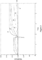
- FIG. 2 shows examples of temperature curves that correspond to different depths of a build surface (up to 1cm depth) that has been covered by an agent (for example a coalescing agent and/or coalescence modifier agent or other agent) during printing.
- Each curve represents the temperature at the surface or at a certain depth, respectively.
- the curve labelled 31 illustrates the temperature at the surface of the agent covered part
- the curve 32 the temperature at a depth of 0.05 cm
- the curve 33 the temperature at a depth of 0.11 cm
- the curve 34 the temperature at a depth of 0.26 cm
- the curve 35 the temperature at a depth of 0.53 cm
- the curve 36 the temperature at a depth of 0.79 cm
- the curve 37 the temperature at a depth of 1 cm.
- the downward spike represents the time when an agent is deposited over the build material (e.g. during printing or depositing an agent).
- the temperature prior to the spike represents a pre-heat temperature applied to the build material, and the temperature after the spike corresponds to a fusing temperature that is applied to coalesce the areas of build material with agent deposited thereon.
- Figure 3 illustrates traces of the heating effect caused by an energy source, for example halogen lamps, over an area which has been printed or covered with an agent.
- Heating of the build surface for example by halogen lamp fusing, provides melting but also uncontrolled excess energy which is transmitted to the raw build material (i.e. areas of the build material which have no agent deposited thereon, also referred to herein as a white area).
- the spike labelled 41 corresponds to a dip in temperature when an agent is deposited, as explained previously in Figure 2 .
- the area labelled 43 corresponds to a period when an energy source, such as a halogen lamp, is heating the portions of build material with coalescing agent to the fusing temperature, i.e.
- the area labelled 45 corresponds to a period when a recoating mechanism shades the build material from the energy source while the recoating mechanism is laying a new layer of build material, thus causing the shaded area to fall in temperature.
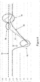
- Figure 4 illustrates an example of temperature evolution during the stages of printing or distributing an agent on a build surface and heating the build surface to the fusing temperature so that the areas with build material and printed agent start to fuse.
- the curve labelled 51 illustrates an example of a temperature curve for the agent covered portions of the build surface during a build process, the dashed line 53 representing the target temperature for fusing.
- the curve labelled 55 illustrates an example of a temperature curve for the raw build material during a build process, the dotted line 57 representing the target temperature for the raw build material.
- the target temperature for the raw build material corresponds to the pre-heating temperature.
- the dip in temperature (labelled with reference 52) may be caused by a carriage shielding the build surface from the energy source, or by an agent distributor depositing an agent, which can lead to a dip in temperature, e.g. as explained above in Figures 2 and 3 .
- energy may be applied via the energy source to compensate for this dip in temperature. In the period labelled 56, this can lead to overheating. This can result in an excess of energy which reduces selectivity by unnecessarily increasing the temperature of the areas with no coalescing agent (i.e. raw build material).
- the examples described herein are related to a method and apparatus for heating a surface during the fabrication of a 3-D object, that is, controlling temperature in an apparatus for generating a three-dimensional object.
- the performance of an apparatus for three dimensional printing can depend on the repeatability of the process and consistency between builds.
- the temperature distribution of the build surface may be controlled to be within a narrow range (for example, ⁇ 1oC). Homogeneity of the temperature distribution over the build surface can also be desirable. This may involve adapting the heat distribution and temperature measurement dynamically to react quickly to changing surface heat distributions.
- fine grain temporal temperature control may be provided to enable selective energy provision to a heating subsystem so that material phase changes are carried out at the correct time and with the optimal amount of energy, without jeopardizing material selectivity.
- the material selectively relates to a surface temperature gap that appears when applying the same amount of energy to an area that is covered by agent with respect to an area that is not covered by agent.
- the material selectivity, or surface temperature gap is large enough such that areas covered with agent can heat to the required temperature for fusing, while areas not covered with agent do not start to fuse.
- An example described herein relates to a method of controlling the energy applied by an energy source to a layer of build material on a build surface, such that at each stage of processing (e.g. spreading, printing/distributing coalescing agent/coalescence modifier agent, fusing) the layer of build material is at an optimal temperature for producing good part quality.
- stage of processing e.g. spreading, printing/distributing coalescing agent/coalescence modifier agent, fusing
- Figure 5 shows an example of a method according to the present disclosure.
- the method comprises controlling the energy radiated by an energy source during a first stage of the fabrication process using a first temperature feedback signal from a first location on the surface, 501.
- the method comprises controlling the energy radiated by an energy source during a second stage of the fabrication process using a second temperature feedback signal from a second location on the surface, 503.
- the first stage may relate to a pre-heating stage of the fabrication process, during which time the first temperature feedback signal is received from a region of the build surface which comprises raw build material, e.g. white powder.
- the method comprises monitoring the temperature of the first location, wherein the first location has raw build material thereon, and using this monitored temperature as the first temperature feedback signal.
- the second stage may comprise, for example, a fusing stage during which a region of build material having an agent thereon is heated to the fusing temperature, during which time the second temperature feedback signal is received from a region of the build surface which comprises printed or treated build material (i.e. build material having an agent deposited thereon).
- the method comprises monitoring the temperature of the second location, wherein the second location has an agent deposited thereon, and using this monitored temperature as the second temperature feedback signal.
- a first stage comprises a pre-heating stage, while a second stage comprises a fusing stage.
- the method comprises controlling the energy source to heat the surface to a first target temperature during the first stage based on the first temperature feedback signal, and controlling the energy source to heat the surface to a second target temperature during the second stage based on the second temperature feedback signal.
- the entire build surface (or powder bed) may be heated uniformly to the pre-heat temperature during the first stage, and the entire build surface (or powder bed) heated uniformly to the fusing temperature during the second stage.
- different zones can have different target temperatures and feedback signals depending upon whether or not they have an agent in them.
- the temperature of a particular zone may be heated to a pre-heat temperature during a first stage and a fusing temperature during a second stage, with feedback signals taken from different areas from within that zone during different stages, e.g. from a white area (with no agent applied theron) of that zone during the first stage, and from an area covered with agent during the second stage.
- a build process may therefore comprise different phases or stages, with a temperature reference for each phase or stage being determined or selected according to what action is being taken in that phase or stage.
- the point (or position) at which temperature is read may be changed dynamically. Different temperature reference points may also be handled simultaneously, for example for different and/or independent processes.
- a first temperature feedback signal is received from a heat sensor, thermometer or thermal imaging camera positioned over the build surface.
- a second temperature feedback signal is received from a heat sensor, thermometer or thermal imaging camera positioned over the build surface.
- the first and second temperature feedback signals may monitor the temperature of the same area of the build surface, or different areas of the build surface such as adjacent, non-overlapping areas of the build surface or in some examples, different, unrelated areas of the build surface.
- the first stage of the build process may be the stage between recoating the build surface with a new layer of build material and printing or distributing coalescence modifier agent or coalescing agent onto the layer of build material.
- the first stage of the build process may be the stage between recoating the build surface with a new layer of build material to when a printed agent, such as a coalescence modifier agent or coalescing agent on the layer of build material has started to coalesce or melt.
- the second stage may correspond to when the layer of build material is heated to the fusing temperature to melt regions of the layer of build material that have been printed with coalescing agent or coalescence modifier agent.
- the first and second stages of the build process may correspond to different stages of the build process.
- a layer printing process can involve dividing the layer printing process (or fabrication process) into multiple stages or phases, where different objective temperatures and different measurement areas are used during the different phases.
- an objective of a first phase might be to reach a stable and homogeneous temperature all over the print bed or build surface, using as reference the raw powder surface temperature.
- an agent for example a coalescing agent and/or coalescence modifier agent and/or other agent, as noted above certain events can cause a decrement of the temperature.
- a carriage which performs this operation can shade a region of the build surface from the heating system, which can result in a slight decrement of the temperature of the build surface.
- an agent being deposited by the pens depicting the cross-section can cause a temperature decrement accentuation on the printed area, compared to the remaining area(s) where no agent is applied.
- a temperature controller detects the temperature decay on the bed and increases the energy applied, to recover the lost temperature.
- a printed part covered with agent accumulates more temperature and arrives at the melting point, while the powder covered area reaches the target temperature (thanks to the selectivity provided by the agent material).
- the melting of the cross section covered by agent is maintained by changing from using a first temperature feedback signal to using a second temperature feedback signal, i.e. changing the reference temperature measurement to the cross-section agent covered area.
- Changing the temperature feedback signal in this way can, in one example, avoid the temperature control mechanism tending to decrement the applied energy (as the target is reached) while a cross-section having coalescing agent thereon is still not completely fused with the build material.
- the method can return to using the first temperature feedback signal, i.e. return to monitoring a raw build material region (white powder), since applying too much energy can decrement the selectivity between the agent covered part and the raw material part.
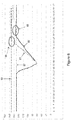
- the effect of this change of temperature feedback signal is illustrated in the example of Figure 6 .
- the curve labelled 61 illustrates an example of a temperature curve for areas of build material with agent deposited thereon during a build process, the dashed line 63 representing the target temperature for areas of build material with agent deposited thereon.
- the curve labelled 65 illustrates an example of a temperature curve for the raw build material during a build process, the dotted line 67 representing the target temperature for the raw build material.
- the temperature is initially controlled to be at the target temperature 67 for raw build material (white target temperature), for example using a first temperature feedback signal which may be taken from a region of the build surface comprising raw build material.
- the dip in temperature may be caused by a carriage shielding the build surface from the energy source, or by an agent distributor depositing an agent, both of which can cause the temperature to fall.
- the system changes to use a second temperature feedback signal to control the energy source, for example taken from a region of the build material which is covered with agent.
- the temperature is controlled to reach a second target temperature corresponding to the target temperature 63 of the coalescing agent or coalescence modifier agent.
- the result is illustrated by reference 64 in Figure 6 , whereby it can be seen that the temperature of the agent rises to match its target temperature 63.
- the part of the curve labelled 66 illustrates that energy modulation is based on the agent covered area causing a certain fluctuation of the temperature on the white (i.e. raw build material) area, however as delivered energy is optimal to maintain the state change of the material, there is not a significant temperature change on the raw build material (white area).
- energy usage can be optimized by changing the target temperature and reference for the sensors so that during the phase change of the material the energy source modulation is targeted to the melting temperature and not the white temperature.
- a temperature control mechanism may use different reference temperature readings (e.g from white area, from a colored area, from an agent covered area, etc%) at different stages during the printing of a layer, or during the printing of different layers.
- phase changes may be triggered by events, timing constraints, temperature readings, or any other event that might benefit from a reference change so the printing process is improved.
- changing between first and second stages may be triggered by: an occurrence of an event; a time period elapsing; or a temperature signal reaching a threshold value.
- An energy source control system for example a lamp control subsystem, may be programmed to achieve a targeted stable and homogeneous temperature all over a printing bed. This may be achieved by controlling the amount of energy provided to a set of lamps that heat the printing or build surface.
- a set of temperature sensors for example Infra Red sensors, thermal cameras, etc.
- Multiple sensors, thermo cameras, etc... may be used, each one monitoring an almost non-overlapping area on the printing bed.
- a temperature map is built using input from sensors and used to feed the lamp control loop.
- the image cross-section information can be reported to the lamp control loop.
- the control loop can compute the energy to be applied to the lamp sub-system according to its location, current temperature, and target temperature and image information.
- a temperature control mechanism according to an example described herein may be provided to match each sensor position with the position of the images being printed, and therefore understand what temperature readings correspond to what parts of the image.
- a position calibration mechanism may be used to determine the previously mentioned matching.
- determining the first location or the second location comprises analysing image data received from thermal or optical imaging to determine a region of the build material having agent deposited thereon, or a region of the build material having no agent deposited thereon. In another example determining the first location or the second location comprises analysing specification data of the 3-D object to determine a region of the build material having agent deposited thereon, or a region of the build material having no agent deposited thereon. In one example, the region or zone to be monitored, or the region or zone to be monitored for providing the temperature feedback signal, can be selected based on the percentage of agent found in that region or zone.
- an energy source control system can be divided into phases or stages which target different purposes.
- one objective might be to keep the raw build material (i.e. white) area with a stable temperature, and right after depositing an agent (i.e. after a printing process) heat up the agent and maintain the state change temperature until the material is fused. At that point a temperature reference change is performed, as described above, so that the melting point is maintained for the necessary amount of time.
- the examples described herein may be extended to include multiple stages or phases with multiple reference points or multiple different temperature feedback signals, for example monitoring the agent temperature during one stage or point, monitoring an inhibitor at some other stage or point, monitoring raw build material (white areas) at some other stage or point, monitoring treated build material (or colored areas) at another stage or point.
- the following procedure illustrates the stages that may occur during the printing of a layer:
- Stage 1 - the target temperature is set to the desired powder temperature (i.e. desired target temperature for raw build material, or white powder).
- Stage 2 - An energy source modulates energy according to a first temperature feedback signal received from a white area, i.e. received from a region comprising raw build material. This may involve using a white control zone or white zones on the print bed or build surface. In one example, image information may be used to discard those parts on the build surface that have agent or parts printed thereon.
- Stage 3 - A second stage is triggered, for example within a predetermined period after depositing agent.
- energy source modulation may be kept to the temperature readings from white or raw build material (i.e. first temperature feedback signal used) until the agent material starts the stage change, i.e. starts to melt.
- the target temperature of the heating subsystem is changed to the melting temperature of the material (i.e. a second target temperature), and the sensor readings are obtained from areas covered with agent (i.e. a second temperature feedback signal is used).
- This can be either from parts of the image being printed (for example based on image information) or from a control area on the printbed covered by agent. In the latter, an area of the printbed can be covered by agent specifically for monitoring purposes, for example corresponding to an area which has a temperature sensor provided for this purpose, while in the former the agent from a known area of the image being printed is used as a reference point.
- Stage 4 After a period of time, for example after a sufficient amount of time necessary to melt the agent covered area, or after a sufficient amount of time for areas covered with agent to fuse with a build material, the target temperature is changed again to the desired powder temperature (white), the first target temperature.
- the sensor input is also changed to the raw build material area, i.e. to using the first temperature feedback signal, such that the temperature is stabilized to this new target.
- some examples described herein can help improve a method of fabricating a 3-D object by improving temperature stability during the printing process. Some examples can improve and stabilize a melting or fusing process without the use of excess energy nor loss of selectivity. The examples provide optimized energy consumption with reduction of surface over-heating, and can improve an overall printing process as a stable temperature can help favour the quality of a 3-D object being fabricated, and improve its mechanical properties.
- controlling the energy radiated by an energy source comprises heating an entire surface of a build surface to a first or second target temperature, or heating a region of the build surface to the first or second target temperature.
- a first region having raw build material may be controlled to be at a first target temperature
- a second region having build material with agent deposited thereon may be controlled to be at a second target temperature.
- Figure 7 shows an example of an apparatus 700 for generating a 3-D object.
- the apparatus comprises at least one sensor 701 to monitor the temperature of a plurality of regions of a surface, and to output at least one temperature feedback signal for each of the plurality of regions.
- the apparatus 700 comprises an energy source 703 (for example a set of lamps which radiate different zones of a printbed).
- the apparatus 700 comprises a temperature controller 705 to control the energy radiated by the energy source 703 during a first stage of the build process using a first temperature feedback signal received from a first location or region, and to control the energy radiated by the energy source 703 during a second stage of the build process using a second temperature feedback signal received from a second location or region.
- the temperature controller 705 controls the energy source to heat the surface to a first target temperature during the first stage based on the first temperature feedback signal, and controls the energy source to heat the surface to a second target temperature during the second stage based on the second temperature feedback signal.
- the first target temperature may comprise, for example, the target temperature of a raw build material.
- the second target temperature may comprise, for example, the target temperature for melting an agent.
- a sensor of the at least one sensors 701 monitors the temperature of a region of the surface having raw build material thereon to provide the first temperature feedback signal.
- a sensor of the at least one sensors 701 monitors the temperature of a region of the surface having agent deposited thereon to provide the second temperature feedback signal.
- a temperature controller 705 for heating a surface while fabricating a 3-D object.
- the temperature controller 705 controls the energy radiated by an energy source during a first stage of the fabrication process using a first temperature feedback signal, and controls the energy radiated by the energy source during a second stage of the fabrication process using a second temperature feedback signal.
- An example described above provides multi-phase based temperature control, which enables energy delivery to be driven and stabilized with the appropriate temperature reference according to the aim of a particular phase of the fabrication process.
- An example described above provides an optimal energy delivery mechanism which is able to target the desired temperature at the different phases during the printing of a layer or across multiple layers. This can help optimize energy delivery, and help avoid excess energy usage which goes in an opposite direction to the maximization of selectivity between agent covered parts and raw material, or any other colored part.
- An example enables optimal melting control by delivering the right amount of energy, and thus improving the overall layer printing process.
- first and second locations during one cycle of a fabrication process may be different to the first and second locations during a second or other subsequent cycles.
Landscapes
- Chemical & Material Sciences (AREA)
- Engineering & Computer Science (AREA)
- Materials Engineering (AREA)
- Manufacturing & Machinery (AREA)
- Physics & Mathematics (AREA)
- Mechanical Engineering (AREA)
- Optics & Photonics (AREA)
- Health & Medical Sciences (AREA)
- Oral & Maxillofacial Surgery (AREA)
- Thermal Sciences (AREA)
- Toxicology (AREA)
Claims (7)
- Procédé de chauffage d'une surface lors de la fabrication d'un objet 3D, le procédé étant caractérisé en ce qu'il comprend :la surveillance, par au moins un capteur (701), de la température de premier et second emplacements sur une surface, etl'émission, par l'au moins un capteur, d'un premier signal de rétroaction de température du premier emplacement et d'un second signal de rétroaction de température du second emplacement ;la régulation de l'énergie rayonnée par une source d'énergie pendant une première étape du processus de fabrication (501) à l'aide du premier signal de rétroaction de température du premier emplacement sur la surface, le premier emplacement ayant un matériau de fabrication brut ; pour réguler ainsi le premier emplacement de manière à ce qu'il soit à une première température cible pendant la première étape ; etla régulation de l'énergie rayonnée par la source d'énergie pendant une second étape du processus de fabrication (503) à l'aide du second signal de rétroaction de température du second emplacement sur la surface, le second emplacement ayant un matériau de fabrication sur lequel est déposé un agent, pour réguler ainsi le second emplacement de manière à ce qu'il soit à une second température cible pendant la seconde étape.
- Procédé selon la revendication 1, comprenant la détermination du premier emplacement ou du second emplacement, la détermination comprenant :l'analyse de données d'image reçues en provenance d'un dispositif imageur thermique ou optique pour déterminer une région du matériau de fabrication sur laquelle un agent a été déposé, ou une région du matériau de fabrication sur laquelle aucun agent n'a été déposé ; oul'analyse de données de spécification de l'objet 3D pour déterminer une région du matériau de fabrication sur laquelle un agent a été déposé, ou une région du matériau de fabrication sur laquelle aucun agent n'a été déposé.
- Procédé selon la revendication 1, caractérisé en ce que le passage de la première à la seconde étape est déclenché par :une occurrence d'un événement ;l'écoulement d'une période de temps ; oul'atteinte par un signal de température d'une valeur seuil.
- Procédé selon la revendication 1, dans lequel la régulation de l'énergie rayonnée par une source d'énergie comprend le chauffage d'une surface de fabrication entière à hauteur d'une première ou d'une seconde température cible, ou le chauffage d'une région de la surface de fabrication à hauteur de la première ou de la seconde température cible.
- Procédé selon la revendication 1, la première étape comprenant une étape de préchauffage.
- Procédé selon la revendication 1, la seconde étape comprenant une étape de fusion.
- Appareil de génération d'objet 3D (700), l'appareil comprenant :un distributeur agent servant à déposer un agent sur du matériau de fabrication ;une source d'énergie (703) ;l'appareil étant caractérisé en ce qu'il comprend :au moins un capteur (701) destiné à surveiller la température d'une pluralité de régions d'une surface, et à émettre au moins un signal de rétroaction de température pour chacune de la pluralité de régions ;un régulateur de température (705) destiné à réguler l'énergie rayonnée par la source d'énergie pendant une première étape du processus de fabrication à l'aide d'un premier signal de rétroaction de température reçu en provenance d'un premier emplacement, le premier emplacement ayant un matériau de fabrication brut, pour réguler ainsi le premier emplacement de manière à ce qu'il soit à une première température cible lors de la première étape ;et destiné à réguler l'énergie rayonnée par la source d'énergie pendant une seconde étape du processus de fabrication à l'aide d'un second signal de rétroaction de température reçu en provenance d'un second emplacement, le second emplacement ayant un matériau de fabrication sur lequel un agent ayant été déposé par le distributeur d'agent, pour réguler ainsi le second emplacement de manière à ce qu'il soit à une seconde température cible pendant la second étape.
Applications Claiming Priority (1)
| Application Number | Priority Date | Filing Date | Title |
|---|---|---|---|
| PCT/EP2015/051963 WO2016119889A1 (fr) | 2015-01-30 | 2015-01-30 | Fabrication d'objets tridimensionnels |
Publications (2)
| Publication Number | Publication Date |
|---|---|
| EP3065935A1 EP3065935A1 (fr) | 2016-09-14 |
| EP3065935B1 true EP3065935B1 (fr) | 2020-05-27 |
Family
ID=52450101
Family Applications (1)
| Application Number | Title | Priority Date | Filing Date |
|---|---|---|---|
| EP15702737.6A Active EP3065935B1 (fr) | 2015-01-30 | 2015-01-30 | Fabrication d'objets tridimensionnels |
Country Status (7)
| Country | Link |
|---|---|
| US (1) | US20170341307A1 (fr) |
| EP (1) | EP3065935B1 (fr) |
| JP (1) | JP6466585B2 (fr) |
| KR (1) | KR101995650B1 (fr) |
| CN (1) | CN107206698B (fr) |
| BR (1) | BR112017016457A2 (fr) |
| WO (1) | WO2016119889A1 (fr) |
Families Citing this family (26)
| Publication number | Priority date | Publication date | Assignee | Title |
|---|---|---|---|---|
| MX355451B (es) | 2014-06-20 | 2018-04-18 | Velo3D Inc | Aparatos, sistemas y metodos para impresion tridimensional. |
| WO2017012656A1 (fr) * | 2015-07-21 | 2017-01-26 | Hewlett-Packard Development Company, L. P. | Mesure de température de génération d'objet |
| US9676145B2 (en) | 2015-11-06 | 2017-06-13 | Velo3D, Inc. | Adept three-dimensional printing |
| JP2019507236A (ja) | 2015-12-10 | 2019-03-14 | ヴェロ・スリー・ディー・インコーポレイテッド | 性能向上した3次元印刷 |
| US20170239719A1 (en) | 2016-02-18 | 2017-08-24 | Velo3D, Inc. | Accurate three-dimensional printing |
| WO2018005439A1 (fr) | 2016-06-29 | 2018-01-04 | Velo3D, Inc. | Impression 3d et imprimantes 3d |
| US11691343B2 (en) | 2016-06-29 | 2023-07-04 | Velo3D, Inc. | Three-dimensional printing and three-dimensional printers |
| EP3397455B1 (fr) * | 2016-10-25 | 2022-07-06 | Hewlett-Packard Development Company, L.P. | Impression tridimensionnelle (3d) |
| WO2018128695A2 (fr) | 2016-11-07 | 2018-07-12 | Velo3D, Inc. | Écoulement des gaz lors de l'impression en trois dimensions |
| US10457033B2 (en) | 2016-11-07 | 2019-10-29 | The Boeing Company | Systems and methods for additively manufacturing composite parts |
| US11440261B2 (en) * | 2016-11-08 | 2022-09-13 | The Boeing Company | Systems and methods for thermal control of additive manufacturing |
| US10766241B2 (en) | 2016-11-18 | 2020-09-08 | The Boeing Company | Systems and methods for additive manufacturing |
| US10843452B2 (en) | 2016-12-01 | 2020-11-24 | The Boeing Company | Systems and methods for cure control of additive manufacturing |
| WO2018129089A1 (fr) | 2017-01-05 | 2018-07-12 | Velo3D, Inc. | Optique dans l'impression en trois dimensions |
| US10369629B2 (en) | 2017-03-02 | 2019-08-06 | Veo3D, Inc. | Three-dimensional printing of three-dimensional objects |
| US20210206081A1 (en) * | 2017-03-14 | 2021-07-08 | Hewlett-Packard Development Company, L.P. | Material development tool |
| US20180281283A1 (en) | 2017-03-28 | 2018-10-04 | Velo3D, Inc. | Material manipulation in three-dimensional printing |
| WO2018194591A1 (fr) | 2017-04-19 | 2018-10-25 | Hewlett-Packard Development Company, L.P. | Sélection de zones de température de réglage de poudre en impression en trois dimensions (3d) |
| US10759159B2 (en) | 2017-05-31 | 2020-09-01 | The Boeing Company | Feedstock lines for additive manufacturing |
| US10814550B2 (en) | 2017-07-06 | 2020-10-27 | The Boeing Company | Methods for additive manufacturing |
| US10821672B2 (en) | 2017-07-06 | 2020-11-03 | The Boeing Company | Methods for additive manufacturing |
| CN111107974B (zh) | 2017-10-04 | 2022-03-04 | 惠普发展公司,有限责任合伙企业 | 增材制造温度 |
| US10272525B1 (en) | 2017-12-27 | 2019-04-30 | Velo3D, Inc. | Three-dimensional printing systems and methods of their use |
| WO2019236050A1 (fr) | 2018-06-04 | 2019-12-12 | Hewlett-Packard Development Company, L.P. | Régulation de caractéristique thermique dans un matériau de construction |
| EP3774287B1 (fr) | 2018-07-31 | 2023-10-11 | Hewlett-Packard Development Company, L.P. | Régulation de la température dans des systèmes de fabrication d'additifs |
| CN114051451A (zh) | 2019-06-18 | 2022-02-15 | 三迪艾姆数字化制造有限公司 | 打印中使用的方法 |
Family Cites Families (14)
| Publication number | Priority date | Publication date | Assignee | Title |
|---|---|---|---|---|
| US5155321A (en) * | 1990-11-09 | 1992-10-13 | Dtm Corporation | Radiant heating apparatus for providing uniform surface temperature useful in selective laser sintering |
| US5730817A (en) * | 1996-04-22 | 1998-03-24 | Helisys, Inc. | Laminated object manufacturing system |
| US6989115B2 (en) * | 1996-12-20 | 2006-01-24 | Z Corporation | Method and apparatus for prototyping a three-dimensional object |
| US20020149137A1 (en) * | 2001-04-12 | 2002-10-17 | Bor Zeng Jang | Layer manufacturing method and apparatus using full-area curing |
| US20040169699A1 (en) * | 2003-02-28 | 2004-09-02 | Hunter Shawn D. | Methods and systems for producing an object through solid freeform fabrication using immiscible fluids |
| US6815636B2 (en) * | 2003-04-09 | 2004-11-09 | 3D Systems, Inc. | Sintering using thermal image feedback |
| US20040254665A1 (en) * | 2003-06-10 | 2004-12-16 | Fink Jeffrey E. | Optimal dimensional and mechanical properties of laser sintered hardware by thermal analysis and parameter optimization |
| DE102004020452A1 (de) * | 2004-04-27 | 2005-12-01 | Degussa Ag | Verfahren zur Herstellung von dreidimensionalen Objekten mittels elektromagnetischer Strahlung und Auftragen eines Absorbers per Inkjet-Verfahren |
| DE102005015870B3 (de) * | 2005-04-06 | 2006-10-26 | Eos Gmbh Electro Optical Systems | Vorrichtung und Verfahren zum Herstellen eines dreidimensionalen Objekts |
| US7718933B2 (en) * | 2007-04-20 | 2010-05-18 | The Boeing Company | Methods and systems for direct manufacturing temperature control |
| GB2493398B (en) * | 2011-08-05 | 2016-07-27 | Univ Loughborough | Methods and apparatus for selectively combining particulate material |
| DE102011053205B4 (de) * | 2011-09-01 | 2017-05-24 | Exone Gmbh | Verfahren zum herstellen eines bauteils in ablagerungstechnik |
| CN103978307B (zh) * | 2014-04-30 | 2015-08-05 | 中国科学院化学研究所 | 一种用于精确控温的高分子材料紫外激光3d打印方法及装置 |
| CN103978687B (zh) * | 2014-04-30 | 2015-08-26 | 中国科学院化学研究所 | 一种应用皮秒激光精确控温3d打印高分子材料系统 |
-
2015
- 2015-01-30 WO PCT/EP2015/051963 patent/WO2016119889A1/fr active Application Filing
- 2015-01-30 JP JP2017535651A patent/JP6466585B2/ja active Active
- 2015-01-30 US US15/535,833 patent/US20170341307A1/en not_active Abandoned
- 2015-01-30 BR BR112017016457-4A patent/BR112017016457A2/pt active Search and Examination
- 2015-01-30 KR KR1020177021126A patent/KR101995650B1/ko active IP Right Grant
- 2015-01-30 EP EP15702737.6A patent/EP3065935B1/fr active Active
- 2015-01-30 CN CN201580074682.3A patent/CN107206698B/zh active Active
Non-Patent Citations (1)
| Title |
|---|
| None * |
Also Published As
| Publication number | Publication date |
|---|---|
| KR101995650B1 (ko) | 2019-09-24 |
| CN107206698B (zh) | 2021-03-12 |
| BR112017016457A2 (pt) | 2018-06-19 |
| US20170341307A1 (en) | 2017-11-30 |
| JP2018501133A (ja) | 2018-01-18 |
| CN107206698A (zh) | 2017-09-26 |
| WO2016119889A1 (fr) | 2016-08-04 |
| KR20170102907A (ko) | 2017-09-12 |
| JP6466585B2 (ja) | 2019-02-06 |
| EP3065935A1 (fr) | 2016-09-14 |
Similar Documents
| Publication | Publication Date | Title |
|---|---|---|
| EP3065935B1 (fr) | Fabrication d'objets tridimensionnels | |
| KR101976970B1 (ko) | 첨가제 제조 시스템의 온도 결정 기법 | |
| EP3426465B1 (fr) | Régulation de la température avant fusion | |
| RU2650155C2 (ru) | Формирование трехмерных объектов | |
| CN107223084B (zh) | 生成3d物体 | |
| EP3044008B1 (fr) | Procédé et dispositif pour contrôler le chauffage d'une surface d'une couche de matériau de construction dans la fabrication additive d'un objet | |
| KR20180124998A (ko) | 인쇄 작용제 적용을 통한 온도 보정 기법 | |
| RU2692342C2 (ru) | Формирование трехмерных объектов | |
| EP3271151B1 (fr) | Chauffage contrôlé pour impression en 3d | |
| US10730242B2 (en) | Controlling temperature in an apparatus for generating a three-dimensional object | |
| EP3356124B1 (fr) | Régulation de température de couche de construction | |
| EP3433073B1 (fr) | Fabrication additive comprenant une région d'irradiation traversante | |
| US11590709B2 (en) | Build layer coverage analysis | |
| US20210370596A1 (en) | Controlling an energy source of an additive manufacturing system | |
| US20220040927A1 (en) | Build material layer control | |
| EP4297958A1 (fr) | Méthodes de fabrication d'objets tridimensionnels et dispositif de contrôle et appareil associés | |
| WO2019125406A1 (fr) | Chauffage variable en fabrication additive |
Legal Events
| Date | Code | Title | Description |
|---|---|---|---|
| PUAI | Public reference made under article 153(3) epc to a published international application that has entered the european phase |
Free format text: ORIGINAL CODE: 0009012 |
|
| 17P | Request for examination filed |
Effective date: 20160411 |
|
| AK | Designated contracting states |
Kind code of ref document: A1 Designated state(s): AL AT BE BG CH CY CZ DE DK EE ES FI FR GB GR HR HU IE IS IT LI LT LU LV MC MK MT NL NO PL PT RO RS SE SI SK SM TR |
|
| AX | Request for extension of the european patent |
Extension state: BA ME |
|
| STAA | Information on the status of an ep patent application or granted ep patent |
Free format text: STATUS: EXAMINATION IS IN PROGRESS |
|
| 17Q | First examination report despatched |
Effective date: 20170717 |
|
| DAX | Request for extension of the european patent (deleted) | ||
| RAP1 | Party data changed (applicant data changed or rights of an application transferred) |
Owner name: HEWLETT-PACKARD DEVELOPMENT COMPANY, L.P. |
|
| REG | Reference to a national code |
Ref country code: DE Ref legal event code: R079 Ref document number: 602015053296 Country of ref document: DE Free format text: PREVIOUS MAIN CLASS: B29C0067000000 Ipc: B29C0064165000 |
|
| GRAP | Despatch of communication of intention to grant a patent |
Free format text: ORIGINAL CODE: EPIDOSNIGR1 |
|
| STAA | Information on the status of an ep patent application or granted ep patent |
Free format text: STATUS: GRANT OF PATENT IS INTENDED |
|
| RIC1 | Information provided on ipc code assigned before grant |
Ipc: B29C 35/02 20060101ALI20200107BHEP Ipc: B33Y 10/00 20150101ALI20200107BHEP Ipc: B33Y 30/00 20150101ALI20200107BHEP Ipc: B33Y 50/02 20150101ALI20200107BHEP Ipc: B29C 64/165 20170101AFI20200107BHEP Ipc: B29C 64/393 20170101ALI20200107BHEP |
|
| INTG | Intention to grant announced |
Effective date: 20200123 |
|
| GRAS | Grant fee paid |
Free format text: ORIGINAL CODE: EPIDOSNIGR3 |
|
| GRAA | (expected) grant |
Free format text: ORIGINAL CODE: 0009210 |
|
| STAA | Information on the status of an ep patent application or granted ep patent |
Free format text: STATUS: THE PATENT HAS BEEN GRANTED |
|
| AK | Designated contracting states |
Kind code of ref document: B1 Designated state(s): AL AT BE BG CH CY CZ DE DK EE ES FI FR GB GR HR HU IE IS IT LI LT LU LV MC MK MT NL NO PL PT RO RS SE SI SK SM TR |
|
| REG | Reference to a national code |
Ref country code: GB Ref legal event code: FG4D |
|
| REG | Reference to a national code |
Ref country code: CH Ref legal event code: EP |
|
| REG | Reference to a national code |
Ref country code: DE Ref legal event code: R096 Ref document number: 602015053296 Country of ref document: DE |
|
| REG | Reference to a national code |
Ref country code: AT Ref legal event code: REF Ref document number: 1274129 Country of ref document: AT Kind code of ref document: T Effective date: 20200615 |
|
| REG | Reference to a national code |
Ref country code: LT Ref legal event code: MG4D |
|
| PG25 | Lapsed in a contracting state [announced via postgrant information from national office to epo] |
Ref country code: NO Free format text: LAPSE BECAUSE OF FAILURE TO SUBMIT A TRANSLATION OF THE DESCRIPTION OR TO PAY THE FEE WITHIN THE PRESCRIBED TIME-LIMIT Effective date: 20200827 Ref country code: GR Free format text: LAPSE BECAUSE OF FAILURE TO SUBMIT A TRANSLATION OF THE DESCRIPTION OR TO PAY THE FEE WITHIN THE PRESCRIBED TIME-LIMIT Effective date: 20200828 Ref country code: IS Free format text: LAPSE BECAUSE OF FAILURE TO SUBMIT A TRANSLATION OF THE DESCRIPTION OR TO PAY THE FEE WITHIN THE PRESCRIBED TIME-LIMIT Effective date: 20200927 Ref country code: PT Free format text: LAPSE BECAUSE OF FAILURE TO SUBMIT A TRANSLATION OF THE DESCRIPTION OR TO PAY THE FEE WITHIN THE PRESCRIBED TIME-LIMIT Effective date: 20200928 Ref country code: FI Free format text: LAPSE BECAUSE OF FAILURE TO SUBMIT A TRANSLATION OF THE DESCRIPTION OR TO PAY THE FEE WITHIN THE PRESCRIBED TIME-LIMIT Effective date: 20200527 Ref country code: SE Free format text: LAPSE BECAUSE OF FAILURE TO SUBMIT A TRANSLATION OF THE DESCRIPTION OR TO PAY THE FEE WITHIN THE PRESCRIBED TIME-LIMIT Effective date: 20200527 Ref country code: LT Free format text: LAPSE BECAUSE OF FAILURE TO SUBMIT A TRANSLATION OF THE DESCRIPTION OR TO PAY THE FEE WITHIN THE PRESCRIBED TIME-LIMIT Effective date: 20200527 |
|
| REG | Reference to a national code |
Ref country code: NL Ref legal event code: MP Effective date: 20200527 |
|
| PG25 | Lapsed in a contracting state [announced via postgrant information from national office to epo] |
Ref country code: HR Free format text: LAPSE BECAUSE OF FAILURE TO SUBMIT A TRANSLATION OF THE DESCRIPTION OR TO PAY THE FEE WITHIN THE PRESCRIBED TIME-LIMIT Effective date: 20200527 Ref country code: BG Free format text: LAPSE BECAUSE OF FAILURE TO SUBMIT A TRANSLATION OF THE DESCRIPTION OR TO PAY THE FEE WITHIN THE PRESCRIBED TIME-LIMIT Effective date: 20200827 Ref country code: RS Free format text: LAPSE BECAUSE OF FAILURE TO SUBMIT A TRANSLATION OF THE DESCRIPTION OR TO PAY THE FEE WITHIN THE PRESCRIBED TIME-LIMIT Effective date: 20200527 Ref country code: LV Free format text: LAPSE BECAUSE OF FAILURE TO SUBMIT A TRANSLATION OF THE DESCRIPTION OR TO PAY THE FEE WITHIN THE PRESCRIBED TIME-LIMIT Effective date: 20200527 |
|
| REG | Reference to a national code |
Ref country code: AT Ref legal event code: MK05 Ref document number: 1274129 Country of ref document: AT Kind code of ref document: T Effective date: 20200527 |
|
| PG25 | Lapsed in a contracting state [announced via postgrant information from national office to epo] |
Ref country code: AL Free format text: LAPSE BECAUSE OF FAILURE TO SUBMIT A TRANSLATION OF THE DESCRIPTION OR TO PAY THE FEE WITHIN THE PRESCRIBED TIME-LIMIT Effective date: 20200527 Ref country code: NL Free format text: LAPSE BECAUSE OF FAILURE TO SUBMIT A TRANSLATION OF THE DESCRIPTION OR TO PAY THE FEE WITHIN THE PRESCRIBED TIME-LIMIT Effective date: 20200527 |
|
| PG25 | Lapsed in a contracting state [announced via postgrant information from national office to epo] |
Ref country code: ES Free format text: LAPSE BECAUSE OF FAILURE TO SUBMIT A TRANSLATION OF THE DESCRIPTION OR TO PAY THE FEE WITHIN THE PRESCRIBED TIME-LIMIT Effective date: 20200527 Ref country code: DK Free format text: LAPSE BECAUSE OF FAILURE TO SUBMIT A TRANSLATION OF THE DESCRIPTION OR TO PAY THE FEE WITHIN THE PRESCRIBED TIME-LIMIT Effective date: 20200527 Ref country code: SM Free format text: LAPSE BECAUSE OF FAILURE TO SUBMIT A TRANSLATION OF THE DESCRIPTION OR TO PAY THE FEE WITHIN THE PRESCRIBED TIME-LIMIT Effective date: 20200527 Ref country code: EE Free format text: LAPSE BECAUSE OF FAILURE TO SUBMIT A TRANSLATION OF THE DESCRIPTION OR TO PAY THE FEE WITHIN THE PRESCRIBED TIME-LIMIT Effective date: 20200527 Ref country code: AT Free format text: LAPSE BECAUSE OF FAILURE TO SUBMIT A TRANSLATION OF THE DESCRIPTION OR TO PAY THE FEE WITHIN THE PRESCRIBED TIME-LIMIT Effective date: 20200527 Ref country code: IT Free format text: LAPSE BECAUSE OF FAILURE TO SUBMIT A TRANSLATION OF THE DESCRIPTION OR TO PAY THE FEE WITHIN THE PRESCRIBED TIME-LIMIT Effective date: 20200527 Ref country code: CZ Free format text: LAPSE BECAUSE OF FAILURE TO SUBMIT A TRANSLATION OF THE DESCRIPTION OR TO PAY THE FEE WITHIN THE PRESCRIBED TIME-LIMIT Effective date: 20200527 Ref country code: RO Free format text: LAPSE BECAUSE OF FAILURE TO SUBMIT A TRANSLATION OF THE DESCRIPTION OR TO PAY THE FEE WITHIN THE PRESCRIBED TIME-LIMIT Effective date: 20200527 |
|
| PG25 | Lapsed in a contracting state [announced via postgrant information from national office to epo] |
Ref country code: SK Free format text: LAPSE BECAUSE OF FAILURE TO SUBMIT A TRANSLATION OF THE DESCRIPTION OR TO PAY THE FEE WITHIN THE PRESCRIBED TIME-LIMIT Effective date: 20200527 Ref country code: PL Free format text: LAPSE BECAUSE OF FAILURE TO SUBMIT A TRANSLATION OF THE DESCRIPTION OR TO PAY THE FEE WITHIN THE PRESCRIBED TIME-LIMIT Effective date: 20200527 |
|
| REG | Reference to a national code |
Ref country code: DE Ref legal event code: R097 Ref document number: 602015053296 Country of ref document: DE |
|
| PLBE | No opposition filed within time limit |
Free format text: ORIGINAL CODE: 0009261 |
|
| STAA | Information on the status of an ep patent application or granted ep patent |
Free format text: STATUS: NO OPPOSITION FILED WITHIN TIME LIMIT |
|
| 26N | No opposition filed |
Effective date: 20210302 |
|
| PG25 | Lapsed in a contracting state [announced via postgrant information from national office to epo] |
Ref country code: SI Free format text: LAPSE BECAUSE OF FAILURE TO SUBMIT A TRANSLATION OF THE DESCRIPTION OR TO PAY THE FEE WITHIN THE PRESCRIBED TIME-LIMIT Effective date: 20200527 |
|
| PG25 | Lapsed in a contracting state [announced via postgrant information from national office to epo] |
Ref country code: MC Free format text: LAPSE BECAUSE OF FAILURE TO SUBMIT A TRANSLATION OF THE DESCRIPTION OR TO PAY THE FEE WITHIN THE PRESCRIBED TIME-LIMIT Effective date: 20200527 |
|
| REG | Reference to a national code |
Ref country code: CH Ref legal event code: PL |
|
| PG25 | Lapsed in a contracting state [announced via postgrant information from national office to epo] |
Ref country code: LU Free format text: LAPSE BECAUSE OF NON-PAYMENT OF DUE FEES Effective date: 20210130 |
|
| REG | Reference to a national code |
Ref country code: BE Ref legal event code: MM Effective date: 20210131 |
|
| PG25 | Lapsed in a contracting state [announced via postgrant information from national office to epo] |
Ref country code: CH Free format text: LAPSE BECAUSE OF NON-PAYMENT OF DUE FEES Effective date: 20210131 Ref country code: LI Free format text: LAPSE BECAUSE OF NON-PAYMENT OF DUE FEES Effective date: 20210131 |
|
| PG25 | Lapsed in a contracting state [announced via postgrant information from national office to epo] |
Ref country code: IE Free format text: LAPSE BECAUSE OF NON-PAYMENT OF DUE FEES Effective date: 20210130 |
|
| PG25 | Lapsed in a contracting state [announced via postgrant information from national office to epo] |
Ref country code: BE Free format text: LAPSE BECAUSE OF NON-PAYMENT OF DUE FEES Effective date: 20210131 |
|
| PG25 | Lapsed in a contracting state [announced via postgrant information from national office to epo] |
Ref country code: HU Free format text: LAPSE BECAUSE OF FAILURE TO SUBMIT A TRANSLATION OF THE DESCRIPTION OR TO PAY THE FEE WITHIN THE PRESCRIBED TIME-LIMIT; INVALID AB INITIO Effective date: 20150130 |
|
| PG25 | Lapsed in a contracting state [announced via postgrant information from national office to epo] |
Ref country code: CY Free format text: LAPSE BECAUSE OF FAILURE TO SUBMIT A TRANSLATION OF THE DESCRIPTION OR TO PAY THE FEE WITHIN THE PRESCRIBED TIME-LIMIT Effective date: 20200527 |
|
| PGFP | Annual fee paid to national office [announced via postgrant information from national office to epo] |
Ref country code: GB Payment date: 20231219 Year of fee payment: 10 |
|
| PGFP | Annual fee paid to national office [announced via postgrant information from national office to epo] |
Ref country code: FR Payment date: 20231219 Year of fee payment: 10 |
|
| PG25 | Lapsed in a contracting state [announced via postgrant information from national office to epo] |
Ref country code: MK Free format text: LAPSE BECAUSE OF FAILURE TO SUBMIT A TRANSLATION OF THE DESCRIPTION OR TO PAY THE FEE WITHIN THE PRESCRIBED TIME-LIMIT Effective date: 20200527 |
|
| PGFP | Annual fee paid to national office [announced via postgrant information from national office to epo] |
Ref country code: DE Payment date: 20231219 Year of fee payment: 10 |