EP3065634B1 - Neurophysiologic monitoring during spine surgery - Google Patents
Neurophysiologic monitoring during spine surgery Download PDFInfo
- Publication number
- EP3065634B1 EP3065634B1 EP14859965.7A EP14859965A EP3065634B1 EP 3065634 B1 EP3065634 B1 EP 3065634B1 EP 14859965 A EP14859965 A EP 14859965A EP 3065634 B1 EP3065634 B1 EP 3065634B1
- Authority
- EP
- European Patent Office
- Prior art keywords
- stimulation
- emg
- channel
- trans
- recording
- Prior art date
- Legal status (The legal status is an assumption and is not a legal conclusion. Google has not performed a legal analysis and makes no representation as to the accuracy of the status listed.)
- Active
Links
- 238000012544 monitoring process Methods 0.000 title claims description 91
- 230000001537 neural effect Effects 0.000 title claims description 36
- 238000001356 surgical procedure Methods 0.000 title description 34
- 230000000638 stimulation Effects 0.000 claims description 376
- 230000004044 response Effects 0.000 claims description 121
- 238000000034 method Methods 0.000 claims description 86
- 230000002232 neuromuscular Effects 0.000 claims description 35
- 210000000118 neural pathway Anatomy 0.000 claims description 19
- 230000010004 neural pathway Effects 0.000 claims description 19
- 238000012545 processing Methods 0.000 claims description 19
- 230000004936 stimulating effect Effects 0.000 claims description 19
- 230000036541 health Effects 0.000 claims description 18
- 230000008859 change Effects 0.000 claims description 15
- 230000001965 increasing effect Effects 0.000 claims description 14
- 238000004088 simulation Methods 0.000 claims description 3
- 230000003862 health status Effects 0.000 claims 1
- 238000012360 testing method Methods 0.000 description 111
- 238000002567 electromyography Methods 0.000 description 101
- PIGYMBULXKLTCJ-UHSSARMYSA-N 1-[(2r,3r,4s,5r)-3,4-dihydroxy-5-(hydroxymethyl)oxolan-2-yl]-1,2,4-triazole-3-carboximidamide;hydrochloride Chemical compound Cl.N1=C(C(=N)N)N=CN1[C@H]1[C@H](O)[C@H](O)[C@@H](CO)O1 PIGYMBULXKLTCJ-UHSSARMYSA-N 0.000 description 90
- 210000005036 nerve Anatomy 0.000 description 69
- 230000006870 function Effects 0.000 description 55
- 230000000763 evoking effect Effects 0.000 description 32
- 239000012190 activator Substances 0.000 description 27
- 210000003205 muscle Anatomy 0.000 description 24
- 230000036461 convulsion Effects 0.000 description 17
- 210000000278 spinal cord Anatomy 0.000 description 16
- 230000037361 pathway Effects 0.000 description 15
- 238000012937 correction Methods 0.000 description 14
- 230000008569 process Effects 0.000 description 12
- 210000001519 tissue Anatomy 0.000 description 12
- 210000003314 quadriceps muscle Anatomy 0.000 description 11
- 210000004761 scalp Anatomy 0.000 description 11
- 238000004891 communication Methods 0.000 description 10
- 230000003247 decreasing effect Effects 0.000 description 8
- 238000001514 detection method Methods 0.000 description 8
- 238000011016 integrity testing Methods 0.000 description 8
- 210000000115 thoracic cavity Anatomy 0.000 description 8
- 210000000988 bone and bone Anatomy 0.000 description 7
- 230000033001 locomotion Effects 0.000 description 7
- 230000002829 reductive effect Effects 0.000 description 7
- 239000000523 sample Substances 0.000 description 7
- 230000000977 initiatory effect Effects 0.000 description 6
- 230000007115 recruitment Effects 0.000 description 6
- 230000004913 activation Effects 0.000 description 5
- 210000004705 lumbosacral region Anatomy 0.000 description 5
- 238000003825 pressing Methods 0.000 description 5
- 238000003860 storage Methods 0.000 description 5
- 241000237970 Conus <genus> Species 0.000 description 4
- 208000007623 Lordosis Diseases 0.000 description 4
- 239000000853 adhesive Substances 0.000 description 4
- 230000001070 adhesive effect Effects 0.000 description 4
- 230000003750 conditioning effect Effects 0.000 description 4
- 230000008878 coupling Effects 0.000 description 4
- 238000010168 coupling process Methods 0.000 description 4
- 238000005859 coupling reaction Methods 0.000 description 4
- 230000007423 decrease Effects 0.000 description 4
- 230000010339 dilation Effects 0.000 description 4
- 210000003128 head Anatomy 0.000 description 4
- 238000005259 measurement Methods 0.000 description 4
- 230000036403 neuro physiology Effects 0.000 description 4
- 230000003238 somatosensory effect Effects 0.000 description 4
- 210000001032 spinal nerve Anatomy 0.000 description 4
- 210000001364 upper extremity Anatomy 0.000 description 4
- 230000000007 visual effect Effects 0.000 description 4
- 210000001260 vocal cord Anatomy 0.000 description 4
- 230000002159 abnormal effect Effects 0.000 description 3
- 238000013459 approach Methods 0.000 description 3
- 230000008901 benefit Effects 0.000 description 3
- 230000015572 biosynthetic process Effects 0.000 description 3
- 230000004397 blinking Effects 0.000 description 3
- 230000006378 damage Effects 0.000 description 3
- 208000037265 diseases, disorders, signs and symptoms Diseases 0.000 description 3
- 238000006073 displacement reaction Methods 0.000 description 3
- 230000009977 dual effect Effects 0.000 description 3
- 230000000694 effects Effects 0.000 description 3
- 238000005516 engineering process Methods 0.000 description 3
- 210000003141 lower extremity Anatomy 0.000 description 3
- 230000015654 memory Effects 0.000 description 3
- 210000000337 motor cortex Anatomy 0.000 description 3
- 230000007383 nerve stimulation Effects 0.000 description 3
- 230000036407 pain Effects 0.000 description 3
- 230000007170 pathology Effects 0.000 description 3
- 210000000578 peripheral nerve Anatomy 0.000 description 3
- 210000001698 popliteal fossa Anatomy 0.000 description 3
- 238000002360 preparation method Methods 0.000 description 3
- 230000002441 reversible effect Effects 0.000 description 3
- 230000003068 static effect Effects 0.000 description 3
- 210000003813 thumb Anatomy 0.000 description 3
- 210000002972 tibial nerve Anatomy 0.000 description 3
- 210000000658 ulnar nerve Anatomy 0.000 description 3
- 210000001113 umbilicus Anatomy 0.000 description 3
- OKTJSMMVPCPJKN-UHFFFAOYSA-N Carbon Chemical compound [C] OKTJSMMVPCPJKN-UHFFFAOYSA-N 0.000 description 2
- 206010023509 Kyphosis Diseases 0.000 description 2
- 230000003187 abdominal effect Effects 0.000 description 2
- 230000003444 anaesthetic effect Effects 0.000 description 2
- 230000002146 bilateral effect Effects 0.000 description 2
- 230000005540 biological transmission Effects 0.000 description 2
- 229910052799 carbon Inorganic materials 0.000 description 2
- 230000015556 catabolic process Effects 0.000 description 2
- 230000006835 compression Effects 0.000 description 2
- 238000007906 compression Methods 0.000 description 2
- 230000002594 corticospinal effect Effects 0.000 description 2
- 230000006735 deficit Effects 0.000 description 2
- 238000006731 degradation reaction Methods 0.000 description 2
- 238000011161 development Methods 0.000 description 2
- 238000010586 diagram Methods 0.000 description 2
- 208000035475 disorder Diseases 0.000 description 2
- 239000000017 hydrogel Substances 0.000 description 2
- 238000003780 insertion Methods 0.000 description 2
- 230000037431 insertion Effects 0.000 description 2
- 210000003127 knee Anatomy 0.000 description 2
- 210000002988 lumbosacral plexus Anatomy 0.000 description 2
- 238000004519 manufacturing process Methods 0.000 description 2
- 210000001595 mastoid Anatomy 0.000 description 2
- 230000013011 mating Effects 0.000 description 2
- 230000028161 membrane depolarization Effects 0.000 description 2
- 210000000944 nerve tissue Anatomy 0.000 description 2
- 230000007935 neutral effect Effects 0.000 description 2
- 230000005236 sound signal Effects 0.000 description 2
- 230000007704 transition Effects 0.000 description 2
- 210000000689 upper leg Anatomy 0.000 description 2
- 206010002091 Anaesthesia Diseases 0.000 description 1
- 208000003618 Intervertebral Disc Displacement Diseases 0.000 description 1
- 206010061246 Intervertebral disc degeneration Diseases 0.000 description 1
- 101100521334 Mus musculus Prom1 gene Proteins 0.000 description 1
- 206010028347 Muscle twitching Diseases 0.000 description 1
- 208000035965 Postoperative Complications Diseases 0.000 description 1
- 208000007103 Spondylolisthesis Diseases 0.000 description 1
- 210000003489 abdominal muscle Anatomy 0.000 description 1
- 230000005856 abnormality Effects 0.000 description 1
- 230000009471 action Effects 0.000 description 1
- 230000036982 action potential Effects 0.000 description 1
- 230000003213 activating effect Effects 0.000 description 1
- 230000002411 adverse Effects 0.000 description 1
- 230000037005 anaesthesia Effects 0.000 description 1
- 230000000712 assembly Effects 0.000 description 1
- 238000000429 assembly Methods 0.000 description 1
- 238000005452 bending Methods 0.000 description 1
- 230000009286 beneficial effect Effects 0.000 description 1
- 210000004556 brain Anatomy 0.000 description 1
- 210000005056 cell body Anatomy 0.000 description 1
- 239000003086 colorant Substances 0.000 description 1
- 230000001010 compromised effect Effects 0.000 description 1
- 239000004020 conductor Substances 0.000 description 1
- 238000012790 confirmation Methods 0.000 description 1
- 210000002808 connective tissue Anatomy 0.000 description 1
- 230000001054 cortical effect Effects 0.000 description 1
- 230000006837 decompression Effects 0.000 description 1
- 208000018180 degenerative disc disease Diseases 0.000 description 1
- 230000003111 delayed effect Effects 0.000 description 1
- 230000003292 diminished effect Effects 0.000 description 1
- 201000010099 disease Diseases 0.000 description 1
- 238000004070 electrodeposition Methods 0.000 description 1
- 210000003811 finger Anatomy 0.000 description 1
- 210000001061 forehead Anatomy 0.000 description 1
- 239000000499 gel Substances 0.000 description 1
- 230000002401 inhibitory effect Effects 0.000 description 1
- 208000014674 injury Diseases 0.000 description 1
- 208000021600 intervertebral disc degenerative disease Diseases 0.000 description 1
- 238000001990 intravenous administration Methods 0.000 description 1
- WABPQHHGFIMREM-UHFFFAOYSA-N lead(0) Chemical compound [Pb] WABPQHHGFIMREM-UHFFFAOYSA-N 0.000 description 1
- 230000000670 limiting effect Effects 0.000 description 1
- 238000012423 maintenance Methods 0.000 description 1
- 210000001617 median nerve Anatomy 0.000 description 1
- 239000002184 metal Substances 0.000 description 1
- 230000000116 mitigating effect Effects 0.000 description 1
- 230000007659 motor function Effects 0.000 description 1
- 229940035363 muscle relaxants Drugs 0.000 description 1
- 239000003158 myorelaxant agent Substances 0.000 description 1
- 230000003287 optical effect Effects 0.000 description 1
- 238000004806 packaging method and process Methods 0.000 description 1
- 230000001769 paralizing effect Effects 0.000 description 1
- 230000000737 periodic effect Effects 0.000 description 1
- 230000002093 peripheral effect Effects 0.000 description 1
- 210000004345 peroneal nerve Anatomy 0.000 description 1
- 230000002980 postoperative effect Effects 0.000 description 1
- 230000002250 progressing effect Effects 0.000 description 1
- 210000002097 psoas muscle Anatomy 0.000 description 1
- 238000011084 recovery Methods 0.000 description 1
- 230000000717 retained effect Effects 0.000 description 1
- 210000000574 retroperitoneal space Anatomy 0.000 description 1
- 238000012552 review Methods 0.000 description 1
- 229920006395 saturated elastomer Polymers 0.000 description 1
- 206010039722 scoliosis Diseases 0.000 description 1
- 239000004065 semiconductor Substances 0.000 description 1
- 230000001953 sensory effect Effects 0.000 description 1
- 230000009155 sensory pathway Effects 0.000 description 1
- 238000004904 shortening Methods 0.000 description 1
- 239000007787 solid Substances 0.000 description 1
- 210000000273 spinal nerve root Anatomy 0.000 description 1
- 230000002269 spontaneous effect Effects 0.000 description 1
- 210000005010 torso Anatomy 0.000 description 1
- 230000008733 trauma Effects 0.000 description 1
- 239000011240 wet gel Substances 0.000 description 1
Images


Classifications
-
- A—HUMAN NECESSITIES
- A61—MEDICAL OR VETERINARY SCIENCE; HYGIENE
- A61B—DIAGNOSIS; SURGERY; IDENTIFICATION
- A61B5/00—Measuring for diagnostic purposes; Identification of persons
- A61B5/48—Other medical applications
- A61B5/4887—Locating particular structures in or on the body
- A61B5/4893—Nerves
-
- A—HUMAN NECESSITIES
- A61—MEDICAL OR VETERINARY SCIENCE; HYGIENE
- A61B—DIAGNOSIS; SURGERY; IDENTIFICATION
- A61B5/00—Measuring for diagnostic purposes; Identification of persons
- A61B5/24—Detecting, measuring or recording bioelectric or biomagnetic signals of the body or parts thereof
- A61B5/316—Modalities, i.e. specific diagnostic methods
- A61B5/389—Electromyography [EMG]
-
- A—HUMAN NECESSITIES
- A61—MEDICAL OR VETERINARY SCIENCE; HYGIENE
- A61B—DIAGNOSIS; SURGERY; IDENTIFICATION
- A61B17/00—Surgical instruments, devices or methods, e.g. tourniquets
- A61B17/02—Surgical instruments, devices or methods, e.g. tourniquets for holding wounds open; Tractors
-
- A—HUMAN NECESSITIES
- A61—MEDICAL OR VETERINARY SCIENCE; HYGIENE
- A61B—DIAGNOSIS; SURGERY; IDENTIFICATION
- A61B17/00—Surgical instruments, devices or methods, e.g. tourniquets
- A61B17/02—Surgical instruments, devices or methods, e.g. tourniquets for holding wounds open; Tractors
- A61B17/0206—Surgical instruments, devices or methods, e.g. tourniquets for holding wounds open; Tractors with antagonistic arms as supports for retractor elements
-
- A—HUMAN NECESSITIES
- A61—MEDICAL OR VETERINARY SCIENCE; HYGIENE
- A61B—DIAGNOSIS; SURGERY; IDENTIFICATION
- A61B5/00—Measuring for diagnostic purposes; Identification of persons
- A61B5/24—Detecting, measuring or recording bioelectric or biomagnetic signals of the body or parts thereof
- A61B5/25—Bioelectric electrodes therefor
- A61B5/279—Bioelectric electrodes therefor specially adapted for particular uses
- A61B5/296—Bioelectric electrodes therefor specially adapted for particular uses for electromyography [EMG]
-
- A—HUMAN NECESSITIES
- A61—MEDICAL OR VETERINARY SCIENCE; HYGIENE
- A61B—DIAGNOSIS; SURGERY; IDENTIFICATION
- A61B5/00—Measuring for diagnostic purposes; Identification of persons
- A61B5/40—Detecting, measuring or recording for evaluating the nervous system
- A61B5/4029—Detecting, measuring or recording for evaluating the nervous system for evaluating the peripheral nervous systems
- A61B5/4041—Evaluating nerves condition
-
- A—HUMAN NECESSITIES
- A61—MEDICAL OR VETERINARY SCIENCE; HYGIENE
- A61B—DIAGNOSIS; SURGERY; IDENTIFICATION
- A61B5/00—Measuring for diagnostic purposes; Identification of persons
- A61B5/40—Detecting, measuring or recording for evaluating the nervous system
- A61B5/4058—Detecting, measuring or recording for evaluating the nervous system for evaluating the central nervous system
- A61B5/407—Evaluating the spinal cord
-
- A—HUMAN NECESSITIES
- A61—MEDICAL OR VETERINARY SCIENCE; HYGIENE
- A61B—DIAGNOSIS; SURGERY; IDENTIFICATION
- A61B17/00—Surgical instruments, devices or methods, e.g. tourniquets
- A61B2017/00017—Electrical control of surgical instruments
- A61B2017/00022—Sensing or detecting at the treatment site
- A61B2017/00039—Electric or electromagnetic phenomena other than conductivity, e.g. capacity, inductivity, Hall effect
-
- A—HUMAN NECESSITIES
- A61—MEDICAL OR VETERINARY SCIENCE; HYGIENE
- A61B—DIAGNOSIS; SURGERY; IDENTIFICATION
- A61B17/00—Surgical instruments, devices or methods, e.g. tourniquets
- A61B2017/00017—Electrical control of surgical instruments
- A61B2017/00115—Electrical control of surgical instruments with audible or visual output
-
- A—HUMAN NECESSITIES
- A61—MEDICAL OR VETERINARY SCIENCE; HYGIENE
- A61B—DIAGNOSIS; SURGERY; IDENTIFICATION
- A61B17/00—Surgical instruments, devices or methods, e.g. tourniquets
- A61B2017/00017—Electrical control of surgical instruments
- A61B2017/00199—Electrical control of surgical instruments with a console, e.g. a control panel with a display
-
- A—HUMAN NECESSITIES
- A61—MEDICAL OR VETERINARY SCIENCE; HYGIENE
- A61B—DIAGNOSIS; SURGERY; IDENTIFICATION
- A61B17/00—Surgical instruments, devices or methods, e.g. tourniquets
- A61B2017/00017—Electrical control of surgical instruments
- A61B2017/00225—Systems for controlling multiple different instruments, e.g. microsurgical systems
-
- A—HUMAN NECESSITIES
- A61—MEDICAL OR VETERINARY SCIENCE; HYGIENE
- A61B—DIAGNOSIS; SURGERY; IDENTIFICATION
- A61B17/00—Surgical instruments, devices or methods, e.g. tourniquets
- A61B2017/00831—Material properties
- A61B2017/00929—Material properties isolating electrical current
-
- A—HUMAN NECESSITIES
- A61—MEDICAL OR VETERINARY SCIENCE; HYGIENE
- A61B—DIAGNOSIS; SURGERY; IDENTIFICATION
- A61B17/00—Surgical instruments, devices or methods, e.g. tourniquets
- A61B17/02—Surgical instruments, devices or methods, e.g. tourniquets for holding wounds open; Tractors
- A61B17/025—Joint distractors
- A61B2017/0256—Joint distractors for the spine
- A61B2017/0262—Joint distractors for the spine with a provision for protecting nerves
-
- A—HUMAN NECESSITIES
- A61—MEDICAL OR VETERINARY SCIENCE; HYGIENE
- A61B—DIAGNOSIS; SURGERY; IDENTIFICATION
- A61B90/00—Instruments, implements or accessories specially adapted for surgery or diagnosis and not covered by any of the groups A61B1/00 - A61B50/00, e.g. for luxation treatment or for protecting wound edges
- A61B90/08—Accessories or related features not otherwise provided for
- A61B2090/0814—Preventing re-use
-
- A—HUMAN NECESSITIES
- A61—MEDICAL OR VETERINARY SCIENCE; HYGIENE
- A61B—DIAGNOSIS; SURGERY; IDENTIFICATION
- A61B2505/00—Evaluating, monitoring or diagnosing in the context of a particular type of medical care
- A61B2505/05—Surgical care
-
- A—HUMAN NECESSITIES
- A61—MEDICAL OR VETERINARY SCIENCE; HYGIENE
- A61B—DIAGNOSIS; SURGERY; IDENTIFICATION
- A61B5/00—Measuring for diagnostic purposes; Identification of persons
- A61B5/74—Details of notification to user or communication with user or patient ; user input means
- A61B5/742—Details of notification to user or communication with user or patient ; user input means using visual displays
- A61B5/743—Displaying an image simultaneously with additional graphical information, e.g. symbols, charts, function plots
Definitions
- the present invention relates to a system generally aimed at surgery. More particularly, the present invention is directed at a system for performing neurophysiologic assessments during surgical procedures.
- the spinal column is a highly complex system of bones and connective tissues that provide support for the body and protect the delicate spinal cord and nerves.
- the spinal column includes a series of vertebral bodies stacked one atop the other, each vertebral body including an inner or central portion of relatively weak cancellous bone and an outer portion of relatively strong cortical bone. Situated between each vertebral body is an intervertebral disc that cushions and dampens compressive forces exerted upon the spinal column.
- a vertebral canal containing the spinal cord is located behind the vertebral bodies.
- spinal column disorders including scoliosis (abnormal lateral curvature of the spine), excess kyphosis (abnormal forward curvature of the spine), excess lordosis (abnormal backward curvature of the spine), spondylolisthesis (forward displacement of one vertebra over another), and other disorders caused by abnormalities, disease or trauma, such as ruptured or slipped discs, degenerative disc disease, fractured vertebrae, and the like. Patients that suffer from such conditions usually experience extreme and debilitating pain as well as diminished nerve function.
- Open surgical techniques are generally undesirable in that they typically require large incisions and high amounts of tissue displacement to gain access to the surgical target site, which produces concomitantly high amounts of pain, lengthened hospitalization (increasing health care costs), and high morbidity in the patient population.
- Less-invasive surgical techniques are gaining favor due to the fact that they involve accessing the surgical target site via incisions of substantially smaller size with greatly reduced tissue displacement requirements. This, in turn, reduces the pain, morbidity, and cost associated with such procedures.
- the surgical access system may include a sequential dilation assembly of increasing diameter and a tissue retraction assembly.
- the sequential dilation assembly is advanced to the surgical target site and the retractor assembly is then advanced to the target site over the sequential dilation system.
- Stimulating electrodes may be provided on the distal tip of one or more different components of the surgical access system.
- Neurophysiologic monitoring may be performed while advancing one or more components of the dilation and retraction assemblies to the target site to detect the presence of, and thereby avoid, nerves lying in the trans-psoas path to the target site.
- a nerve may become compromised due to a variety of factors including, but not limited to, compression of the nerve due to inadvertent contact with the retractor blade and patient positioning on the surgical table. Stimulating within the surgical site provides information regarding the health and status of nearby nerves within the surgical site during maintenance of the lateral access corridor. However, the portion of a nerve that is compressed or otherwise affected may not lie within the surgical site such that information regarding the health and status of a greater portion of the motor neural pathway is desirable.
- MEP transcranial electric motor evoked potential monitoring
- Other methods of stimulating the motor neural pathway use multi-pulse trains of stimuli with high stimulus intensities and depolarize all nerves along the corticospinal pathway and result in muscle activity of many muscles of the head, upper extremities, torso, and lower extremities.
- This whole-body stimulation can sometimes lead to large amounts of patient movement during the procedure.
- MEP monitoring is also disadvantageous for monitoring the lower motor neural pathway in that requires the use of total intravenous anesthesia (TIVA).
- TIVA requires close monitoring and is also more expensive than other anesthetic regimens.
- each specific nerve root is also desirable because it provides specific information regarding the health and/or status of each nerve root comprising the lumbar plexus. Therefore, a need exists for systems and methods of performing neurophysiologic monitoring on a greater portion of the motor neural pathway, lower amounts of stimulation intensity, shorter pulses, well-received anesthetic requirements, greater specificity of the at-risk nerve roots and earlier indications of potential post-operative complications such that mitigating actions may be taken.
- the present invention provides a non-transitory computer-readable medium for monitoring the health of the lower motor neural pathway during a spinal procedure, as set out in claim 1.
- the present disclosure includes systems and methods to evaluate the health and status of the lower motor neural pathway before, during and after the establishment of an operative corridor through (or near) any of a variety of tissues having such neural structures which, if contacted or impinged, may otherwise result in neural impairment for the patient.
- the system and methods of the present disclosure are suitable for use in any number of additional spinal surgeries including posterior, posterolateral, anterior, anterolateral lumbar spinal surgeries as well as thoracic and thoracolumbar spinal surgeries.
- the present disclosure is suitable for use in any number of additional surgical procedures wherein tissue having significant neural structures must be passed through (or near) in order to establish an operative corridor.
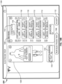
- the present disclosure includes a control unit, a patient module, and a plurality of surgical accessories adapted to couple to the patient module.
- the control unit includes a power supply and is programmed to receive user commands, activate stimulation in a plurality of predetermined modes, process signal data according to defined algorithms, display received parameters and processed data, and monitor system status.
- the patient module is in communication with the control unit.
- the patient module is within the sterile field.
- the patient module includes signal conditioning circuitry, stimulator drive circuitry, and signal conditioning circuitry required to perform said stimulation in said predetermined modes.
- the patient module includes a processor programmed to perform a plurality of predetermined functions including at least two of neuromuscular pathway assessment, non-evoked monitoring, static pedicle integrity testing, dynamic pedicle integrity testing, nerve proximity detection, manual motor evoked potential monitoring, automatic motor evoked potential monitoring, transcutaneous nerve root testing, manual somatosensory evoked potential monitoring, automatic somatosensory evoked potential monitoring, and surgical correction planning and assessment.
- a processor programmed to perform a plurality of predetermined functions including at least two of neuromuscular pathway assessment, non-evoked monitoring, static pedicle integrity testing, dynamic pedicle integrity testing, nerve proximity detection, manual motor evoked potential monitoring, automatic motor evoked potential monitoring, transcutaneous nerve root testing, manual somatosensory evoked potential monitoring, automatic somatosensory evoked potential monitoring, and surgical correction planning and assessment.
- the present disclosure includes a processing unit programmed to perform a plurality of predetermined functions using said instrument including at least two of neuromuscular pathway assessment, static pedicle integrity testing, dynamic pedicle integrity testing, nerve proximity detection, transcutaneous nerve root testing, non-evoked monitoring, motor evoked potential monitoring, somatosensory evoked potential monitoring, and surgical correction planning and assessment.
- the processing system has a pre-established profile for at least one of said predetermined functions so as to facilitate the initiation of said at least one predetermined function.
- a method for performing transcutaneous, trans-abdominal stimulation of the lumbar motor neural pathways superior and inferior to a surgical target site is provided.
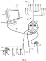
- a neurophysiologic monitoring system 10 is described herein and is capable of performing a number of neurophysiological and/or guidance assessments at the direction of the surgeon (and/or other members of the surgical team).
- Figs. 1-2 illustrate the basic components of the system 10.
- the system comprises a control unit 12 (including a main display 34 preferably equipped with a graphical user interface (GUI) and a processing unit 36 that collectively contain the essential processing capabilities for controlling the system 10), a patient module 14, a stimulation accessory (e.g. a stimulation probe 16, stimulation clip 18 for connection to various surgical instruments, an inline stimulation hub 20, and stimulation electrodes 22), and a plurality of recording electrodes 24 for detecting electrical potentials.
- GUI graphical user interface
- the stimulation accessories may be in the form of various prove devices that are themselves inserted into the stimulation site, clips that attach and deliver stimulation signals to standard instruments that are used at various times throughout a procedure...and surface electrodes.
- the stimulation clip 18 may be used to connect any of a variety of surgical instruments to the system 10, including, but not necessarily limited to a pedicle access needle 26, k-wire 27, tap 28, dilator(s) 30, tissue retractor 32, etc.
- One or more secondary feedback devices e.g. secondary display 46 in Fig. 20-21 ) may also be provided for additional expression of output to a user and/or receiving input from the user.
- the system 10 may be configured to execute any of the functional modes including, but not necessarily limited to, neuromuscular pathway assessment ("Twitch Test”), non-evoked monitoring (“Free-run EMG”), static pedicle integrity testing (“Basic Stimulated EMG”), dynamic pedicle integrity testing (“Dynamic Stimulated EMG”), nerve proximity detection (“XLIF ® “), motor evoked potential monitoring (“MEP Manual” and “MEP Automatic”), transcutaneous nerve root testing (“TCNR Alert” and “TCNR Threshold”), somatosensory evoked potential monitoring (“SSEP Manual” and “SSEP Automatic”), and surgical correction planning and assessment.
- the system 10 may also be configured for performance in any of the lumbar, thoracolumbar, and cervical regions of the spine.
- the basis for performing many of these functional modes is the assessment of evoked responses of the various muscles myotomes monitored by the system 10 in relation to a stimulation signal transmitted by the system 10 (via patient module 14).
- the assessment of the evoked responses can be any suitable means of sensing physical motion of a muscle, for example via mechanomyography (MMG) which entails using an accelerometer or other similar device for detecting mechanical movement of a muscle or via electromyography (EMG) which is described in detail herein. This is illustrated in Figs.
- Fig. 5 illustrates the resulting EMG waveform of a monitored myotome in response to one of the example stimulation signals represented in Fig. 3 and Fig. 4 .
- the EMG responses provide a quantitative measure of the nerve depolarization caused by the electrical stimulus.
- One way to characterize the EMG response is by a peak-to-peak voltage of V pf , , V max -V mhi , as shown in Fig. 5 .
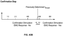
- Nerve tissues have characteristic threshold current levels (th res h) at which they will depolarize and result in a detectable muscle activity. Below this threshold current level, a stimulation signal will not evoke a significant EMG response.
- a significant EMG response may be defined as having a v pp of approximately 100uV.
- the lowest stimulation current necessary to evoke an EMG response of the threshold voltage (V t h res h), 100uV in this example may be called h res h.
- an excessively high Ithresh or an increase over a previous measurement during MEP testing may indicate a problem in the spinal cord or other portion of the motor pathway inhibiting transmission (communication) of the stimulation signal to the nerve.
- a low 'thresh value may indicate a breach in the pedicle allowing the electrical signal to transmit through the pedicle, or the close proximity of a nerve to the stimulation source, respectively.
- the surgeon may detect a problem or potential problem early and then act to avoid and/or mitigate the problem.
- the neurophysiology system 10 may quickly and accurately determine Ithresh under the direction and operation of the surgeon (if desired) and convey the useful information I t h res h contains in a simple and easily comprehensible manner for interpretation by the surgeon.
- the control unit 12 of the system 10 includes a main display 34 and a processing unit 36, which collectively contain the essential processing capabilities for controlling the system 10.
- the main display 34 is preferably equipped with a graphical user interface (GUI) capable of graphically communicating information to the user and receiving instructions from the user.
- GUI graphical user interface
- the processing unit 36 contains computer hardware and software that commands the stimulation source (e.g. patient module 14, Figs. 7-9 ), receives digital and/or analog signals and other information from the patient module 14, processes EMG and SSEP response signals, and displays the processed data to the user via the display 34.
- the primary functions of the software within the control unit 12 include receiving user commands via the touch screen main display 34, activating stimulation in the appropriate mode (Twitch Test, Basic Stimulated EMG, Dynamic Stimulated EMG, XLIF, MEP Manual, MEP Automatic, TCNR Alert, TCNR Threshold, SSEP Manual, and SSEP Automatic), processing signal data according to defined algorithms, displaying received parameters and processed data, and monitoring system status.
- the main display 34 may comprise a 15" LCD display equipped with suitable touch screen technology and the processing unit 36 may comprise a 2GHz.
- the processing unit 36 shown in Fig. 6 further includes a powered USB port 38 for connection to the patient module 14, a media drive 40 (e.g.
- control unit 12 sits near the surgical table but outside the surgical field, such as for example, on a table top or a mobile stand. It will be appreciated, however, that if properly draped and protected, the control unit 12 may be located within the surgical (sterile) field.
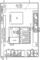
- the patient module 14 shown by way of example only in Figs. 4-6 , is communicatively linked to the control unit 12.
- the patient module 14 is communicatively linked with and receives power from the control unit 12 via a USB data cable 44.
- the patient module 14 may be supplied with its own power source and other known data cables, as well as wireless technology, may be utilized to establish communication between the patient module 14 and control unit 12.
- the patient module 14 contains a digital communications interface to communicate with the control unit 12, as well as the electrical connections to all recording and stimulation electrodes, signal conditioning circuitry, stimulator drive and steering circuitry, and signal conditioning circuitry required to perform all of the functional modes of the system 10, including but not necessarily limited to Twitch Test, Free-run EMG, Basic Stimulated EMG, Dynamic Stimulated EMG, XLIF, MEP Manual and MEP Automatic, TCNR Alert, TCNR Threshold, SSEP Manual, and SSEP Automatic.
- the patient module 14 includes thirty-two recording channels and eleven stimulation channels.
- a display e.g.
- an LCD screen may be provided on the face of the patient module 14, and may be utilized for showing simple status readouts (for example, results of a power on test, the electrode harnesses attached, and impedance data, etc%) or more procedure related data (for example, a stimulation threshold result, current stimulation level, selected function, etc).
- the patient module 14 may be positioned near the patient in the sterile field during surgery.
- the patient module 14 may be attached to bed rail with the aid of a hook 48 attached to, or forming a part of, the patient module 14 casing.
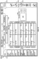
- patient module 14 comprises a multitude of ports and indicators for connecting and verifying connections between the patient module 14 and other system components.
- a control unit port 50 is provided for data and power communication with the control unit 12, via USB data cable 44 as previously described.
- accessory ports 52 provided for connecting up to the same number of surgical accessories, including, but not necessarily limited to, stimulation probe 16, stimulation clip 18, inline stimulation hub 20, and navigated guidance sensor (or tilt sensor) 54.
- the accessory ports 52 include a stimulation cathode and transmit digital communication signals, tri-color LED drive signals, button status signals, identification signals, and power between the patient module 14 and the attached accessory.
- a pair of anode ports 56 may be used to attach auxiliary stimulation anodes should it become desirable or necessary to do so during a procedure.
- a pair of USB ports 58 are connected as a USB hub to the control unit 12 and may be used to make any number of connections, such as for example only, a portable storage drive.
- the system 10 automatically performs a circuit continuity check to ensure the associated device will work properly.
- Each device forms a separate closed circuit with the patient module such that the devices may be checked independent of each other. If one device is not working properly the device may be identified individually while the remaining devices continue indicate their valid status.
- An indicator LED is provided for each port to convey the results of the continuity check to the user.
- the patient module 14 includes one control unit indicator 60, four accessory indicators 62, two anode indicators 64, and two USB indicators 66. If the system detects an incomplete circuit during the continuity check, the appropriate indicator will turn red alerting the user that the device might not work properly.
- the indicator will appear green signifying that the device should work as desired. Additional indicator LEDs are provided to indicate the status of the system and the MEP stimulation.
- the system indicator 68 will appear green when the system is ready and red when the system is not ready.
- the MEP stim indicator 70 lights up when the patient module is ready to deliver and MEP stimulation signal.
- the MEP stim indicator 68 appears yellow to indicate a ready status.
- the patient module 14 also includes a plurality of electrode harness ports.
- the patient module 14 includes an EMG/MEP harness port 72, SSEP harness port 74, an Auxiliary harness port 76 (for expansion and/or custom harnesses; e.g, a TCNR harness).
- Each harness port 72, 74, and 76 includes a shaped socket 78 that corresponds to a matching shaped connector 82 on the appropriate electrode harness 80.
- the system 10 may preferably employ a color code system wherein each modality (e.g. EMG, EMG/MEP, and SSEP) has a unique color associated with it.
- EMG monitoring including, screw tests, detection, and nerve retractor
- MEP monitoring with the color blue
- SSEP monitoring may be associated with the color orange.
- each harness port 72, 74, 76 is marked with the appropriate color which will also correspond to the appropriate harness 80.
- the patient module 14, and especially the configuration of quantity and layout of the various ports and indicators, has been described according to one example . It should be appreciated, however, that the patient module 14 could be configured with any number of different arrangements without departing from the scope of the invention.
- all of the recording electrodes 24 and stimulation electrodes 22 that are required to perform one of the various functional modes are bundled together and provided in single electrode harness 80, as illustrated, by way of example only, in Fig. 10 .
- a common electrode 23 providing a ground reference to pre-amplifiers in the patient module 14, and an anode electrode 25 providing a return path for the stimulation current
- single electrode harness 80 provides single electrode harness 80, as illustrated, by way of example only, in Fig. 10 .
- different groupings of recoding electrodes 24 and stimulation electrodes 22 may be required.
- the SSEP function requires more stimulating electrodes 22 than either the EMG or MEP functions, but also requires fewer recording electrodes than either of the EMG and MEP functions.
- the system 10 may employ different harnesses 80 tailored for the desired modes.
- Three different electrode harnesses 80 may be provided for use with the system 10, an EMG harness, an EMG/MEP harness, and an SSEP harness.
- the shaped connector 82 interfaces with the shaped socket 72, 74, or 76 (depending on the functions harness 80 is provided for).
- Each harness 80 utilizes a shaped connector 82 that corresponds to the appropriate shaped socket 72, 74, 76 on the patient module 14. If the shapes of the socket and connector do not match the harness 80, connection to the patient module 14 cannot be established.
- the EMG and the EMG/MEP harnesses both plug into the EMG/MEP harness port 72 and thus they both utilize the same shaped connector 82.
- Figs. 11A-11C illustrate the various shape profiles used by the different harness ports 72, 74, 76 and connectors 82.
- Each harness connector 82 includes a digital identification signal that identifies the type of harness 80 to the patient module 14.
- a plurality of electrode connectors 102 linked to the harness connector 82 via a wire lead.
- any of a variety of known electrodes may be used, such as by way of example only, surface dry gel electrodes, surface wet gel electrodes, and needle electrodes.
- an electrode cap 81 depicted by way of example only in Fig. 13A may be used.
- the electrode cap 81 includes two recording electrodes 23 for SSEP monitoring, two stimulation electrodes 22 for MEP stimulation delivery, and an anode 23.
- Graphic indicators may be used on the electrode cap 81 to delineate the different electrodes.
- lightning bolts may be used to indicate a stimulation electrode
- a circle within a circle may be used to indicate recording electrodes
- a stepped arrow may be used to indicate the anode electrode.
- the anode electrode wire is colored white to further distinguish it from the other electrodes and is significantly longer that the other electrode wires to allow placement of the anode electrode on the patient's shoulder.
- the shape of the electrode cap 81 may also be designed to simplify placement.
- the cap 81 has a pointed end that may point directly toward the patient's nose when the cap 81 is centered on the head in the right orientation.
- a single wire may connect the electrode cap 81 to the patient module 14 or electrode harness 80, thereby decreasing the wire population around the upper regions of the patient.
- the cap 81 may be equipped with a power supply and a wireless antenna for communicating with the system 10.
- Fig. 13B illustrates another example of an electrode cap 83 similar to cap 81.
- the stimulation electrodes 22 are colored yellow, the recording electrodes 24 are gray, and the anode electrode 23 is white.
- the anode electrode is seen here configured for placement on the patient's forehead.
- the electrode cap (not shown) may comprise a strap or set of straps configured to be worn on the head of the patient.
- the appropriate scalp recording and stimulation sites may be indicated on the straps.
- the electrode cap may be imbued with holes overlying each of the scalp recording sites (for SSEP) and scalp stimulation sites (for MEP).
- the border around each hole may be color coded to match the color of an electrode lead wire designated for that site.
- the recording and stimulation electrodes designated for the scalp are preferably one of a needle electrode and a corkscrew electrode that can be placed in the scalp through the holes in the cap.
- the electrodes of different sizes and configurations may be preferable for the TCNR mode than for MEP, EMG, and SSEP modes.
- the posterior cathode is a single use cathode electrode that has a circular shape (radially symmetric) to simplify positioning (superficially on the dorsal midline, approximately over the conus medullaris at the L1-L2 spinal level).
- the full contact surface is a conductive adhesive hydrogel to eliminate the need for skin prep.
- the connecting lead is made of insulated radiolucent carbon wire to avoid obscuring fluoroscopic images.
- the terminating 1.5mm female DIN connector is color coded purple to maintain correct polarity corresponding with the mating harness connector.
- the anterior anode is a single use anode electrode has a square shape (radially symmetric) with a relatively large surface area to simplify positioning (superficially on the abdominal midline below the umbilicus) and increase the positioning location tolerance.
- the full contact surface is a conductive adhesive hydrogel to eliminate the need for skin prep.
- the connecting lead is made of insulated radiolucent carbon wire to avoid obscuring fluoroscopic images.
- the terminating 1.5mm female DIN connector is color coded yellow maintain correct polarity corresponding with the mating harness connector.
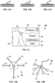
- each wire lead next to the electrode connector 102 may be tagged with a label 86 that shows or describes the proper positioning of the electrode on the patient.
- the label 86 preferably demonstrates proper electrode placement graphically and textually. As shown in Fig. 12 , the label may include a graphic image showing the relevant body portion 88 and the precise electrode position 90. Textually, the label 86 may indicate the side 100 and muscle (or anatomic location) 96 for placement, the function of the electrode (e.g. stimulation, recording channel, anode, and reference - not shown), the patient surface (e.g. anterior or posterior), the spinal region 94, and the type of monitoring 92 (e.g.
- the electrode harnesses 80 are designed such that the various electrodes may be positioned about the patient (and preferably labeled accordingly) as described in Table 1 for Lumbar EMG, Table 2 for Cervical EMG, Table 3 for Lumbar/Thoracolumbar EMG and MEP, Table 4 for Cervical EMG and MEP, Table 5 for TCNR, and Table 6 for SSEP: Table 1: Lumbar EMG Electrode Type Electrode Placement Spinal Level Ground Upper Outer Thigh Anode Latissimus Dorsi Stimulation Knee Recording Left Tibialis Anterior IA, L5 Recording Left Gastroc.
- the patient module 14 is configured such that the system 10 may conduct an impedance test under the direction of the control unit 12 of all electrodes once the system is set up and the electrode harness is connected and applied to the patient. After choosing the appropriate spinal site upon program startup (described below), the user is directed to an electrode test.
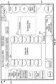
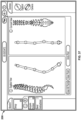
- Figs. 14A-14B illustrate, by way of example only, a graphical implementation capturing the features of an electrode test[s] as implemented on an electrode test screen 104.
- the electrode test screen 104 includes a human figure depiction with positioned electrodes 108.
- a harness indicator 109 displays which harness is in use.
- the anode 23 and common 25 are both provided as dual electrodes. At least one of the anode leads on the anode electrode is reversible. During the impedance check, the reversible anode lead switches to a cathode such that the impedance between the leads can be measured. When the impedance test is complete, the reversible lead switches back to an anode.
- the channel button 110 may be labeled with the muscle or coverage area of the corresponding electrode. Selecting the channel button 110 will disable the channel.
- Disabled channels will not be tested for impedance and they will not be monitored for responses or errors unless reactivated.
- a start button 106 (“Run Electrode Test")
- the system tests each electrode individually to determine the impedance value. If the impedance is determined to be within acceptable limits, the channel button 110 and electrode depiction on the human figure 108 turn green. If the impedance value for any electrode is not determined to be acceptable, the associated channel button 110 and electrode depiction turn red, alerting the user. Once the test is complete, selecting the "Accept" button 112 will open the main monitoring screen 200 of the system 10.
- the system 10 may utilize various stimulation accessories to deliver stimulation signals to a stimulation target site such as over the patient's conus medullaris, a hole formed or being formed in a pedicle, and/or tissue surrounding an access corridor.
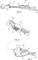
- Figs. 15-17 illustrate an example of a stimulation accessory in the form of a stimulation clip 18 that permits the system 10 to deliver stimulation signals through various surgical instruments already used during the surgical procedure.
- the coupling device 18 may connect the system 10 with instruments including, but not necessarily limited to, a pedicle access needle 26, a tap 28, dilator 30, tissue retractor 32, and k-wire 27.
- the stimulation clip 18 utilizes a spring-loaded plunger 128 to hold the surgical tool and transmit the stimulation signal thereto.
- the plunger 128 is composed of a conductive material such as metal.
- a nonconductive housing 130 partially encases the plunger 128 about its center. Extending from the housing 130 is an endplate 132 that hooks the surgical instrument.
- a spring (not shown) is disposed within the housing 130 such that in a natural or "closed” state, the plunger 128 is situated in close proximity to the endplate 132. Exerting a compressive force on the spring (such as by pulling on the thumb grip 134) causes a gap between the end plate 132 and the plunger 128 to widen to an "open" position (shown in Figs. 15-17 thereby allowing insertion of a surgical tool between the endplate 132 and plunger 128.
- the clip 18 further includes a button module 129 containing an activation button 131 for initiating stimulation.
- the button module 129 is set apart from the body of the clip 18 and they are linked by an integrated wire.
- An accessory port 133 is located next to the button 131 on the button module 129, thus minimizing the number of wires connecting back to the patient module 14 and outside the sterile field.
- Clip 18 is equipped with three LEDs 135, 137, and 139.
- LED 135 is associated with the accessory port 133 and LED 137 is associated with the clip 18 to indicate which of the two is stimulating.
- the LEDs 137 and 137 may appear purple when stimulation is active.
- the associated LED 135 or 137 may appear either red (if the result meets a predetermined potentially unsafe value), green (if the result meets a predetermined safe value), or yellow (if the result is in between the safe and potentially unsafe values).
- a third LED 139 is contained within the thumb grip 134, which will appear red, yellow, or green depending on the threshold result.
- the clip 18 connects to one of the accessory ports 62 on the patient module 14 via a connector 136.
- the connector 136 includes an identification signal that identifies it to the patient module.
- Fig. 18A illustrates a second example of a stimulation accessory in the form of an in-field activator 330.
- the activator 330 is preferably a single-use sterile device and may be designed [as] a stand-alone device designed to interface with the patient module 14 independently or may be part of an assembly as will be explained below.
- the activator 330 may plug into an accessory port 133 of the stimulation clip 18 of Figs. 15-17 above to provide user control and status indication of the TCNR mode from inside the sterile field during the surgical procedure.
- Fig. 19 shows the activator 330 plugged into accessory port 133 for in-field use.
- the activator 330 is compatible with module 129 such that the activator 330 and clip 18 may be jointly connected to the system 10 via module 129 without the need for additional components, additional wires, and the like.
- the activator 330 includes a top 331, a bottom 332, a housing 333, a first end 334, a second end 336, a connection plug 338 emanating from said first end 334, a stimulation button 334 and a multicolor LED indicator 342 disposed between ends 334, 336.
- the connection plug 338 is sized and dimensioned to fit within the accessory port 133.
- Activator 330 may include one or more securing clips 348 ( Fig.
- the activator 330/stimulation clip 18 assembly may be connected to one of the accessory ports 62 on the patient module 14 via a connector 136.
- the connector 136 includes an identification signal that identifies it to the patient module.
- the activator button 330 allows a user from the sterile field to both navigate to the TCNR mode and initiate trans-abdominal, transcutaneous stimulation in TCNR modes with a single button press.
- the activator 330 may allow a user to both access the TCNR mode and initiate TCNR stimulation with a single button press as will be described in greater detail below.
- the activation button 340 may be circular and is protected from unintended activation by a raised surrounding border. Finger grips 334 may be provided on the sides of the activator housing 332 near activation button 340 to stabilize the activator 330 during use.
- the activator 342 is equipped with a multi-color LED indicator 342.
- the stimulation button 340 and the LED indicator 342 are two distinct components.
- the LED indicator 342 is integrated into the stimulation button 340.
- LED indicator 342 provides feedback to the user of various states of operation of the TCNR modality. By way of example only, LED indicator 342 will illuminate when the timer has expired, when the stimulator button 340 has been pressed and when the system 10 is delivering stimulation.
- Table 7 LED Visual Feedback Indication or Assessment Off Timer not elapsed, stimulation is inactive, or modality not selected Blinking Green 1 Hz rat Primary timer (default 5 min) has elapsed since last stimulation Blinking Green 2 Hz rate Secondary timer (default 10 min) has elapsed since last stimulation Blinking Amber 4 Hz rate Stimulation is active Solid Green Previous result- no significant change from baseline Steady Yellow Previous result- noteworthy change from baseline Steady Red Previous result- significant change from baseline
- the system 10 may include a secondary display, such as for example only, the secondary display 46 illustrated in Figs. 20-21 .
- the secondary display 46 may be configured to display some or all of the information provided on main display 34.
- the information displayed to the user on the secondary display 34 may include, but is not necessarily limited to, alpha-numeric and/or graphical information regarding any of the selected function modes (e.g. Twitch Test, Free-Run EMG, Basic Stimulated EMG, Dynamic Stimulated EMG, XLIF, MEP Manual, MEP Automatic, TCNR Alert, TCNR Threshold, SSEP Manual, SSEP Automatic, and surgical correction planning and assessment), attached accessories (e.g.
- Secondary display 46 may be configured to receive user input in addition to its display function.
- the secondary display 46 can thus be used as an alternate control point for the system 10.
- the control unit 12 and secondary display 46 may be linked such that input may be received on from one display without changing the output shown on the other display. This would allow the surgeon to maintain focus on the patient and test results while still allowing other members of the OR staff to manipulate the system 10 for various purposes (e.g. inputting annotations, viewing history, etc).
- the secondary display 46 may be battery powered.
- the secondary display 46 may be positioned inside the sterile field as well as outside the sterile field.
- a disposable sterile case 47 may be provided to house the display.
- the display 46 may be sterile bagged. Both the sterile case 47 and the secondary display 46 may be mounted to a pole, bed frame, light fixture, or other apparatus found near and/or in the surgical field. It is further contemplated that multiple secondary displays 46 may be linked to the control unit 12. This may effectively distribute neurophysiology information and control throughout the operating room.
- a secondary display 46 may also be provided for the anesthesiologist.
- Wired or wireless technology may be utilized to link the secondary display 46 to the control unit 12.
- the startup screen includes a profile selection window 160 from which the user may select from one of the standard profiles (e.g. "Standard Cervical,” “Standard Thoracolumbar,” and “Standard Lumbar”) or any custom profiles that have been previously saved to the system. Profiles may be arranged for selection, alphabetically, by spinal region, or by other suitable criteria. Profiles may be saved to the control unit hard drive or to a portable memory device, such as for example, a USB memory drive, or on a web server.
- standard profiles e.g. "Standard Cervical,” "Standard Thoracolumbar,” and "Standard Lumbar”
- Profiles may be arranged for selection, alphabetically, by spinal region, or by other suitable criteria. Profiles may be saved to the control unit hard drive or to a portable memory device, such as for example, a USB memory drive, or on a web server.
- Selecting a profile configures the system 10 to the parameters assigned for the selected profile (standard or custom).
- the availability of different function modes may depend upon the profile selected.
- selecting the cervical and thoracolumbar spinal regions may automatically configure the options to allow selection of the Twitch Test, SSEP Manual, SSEP Automatic, Basic Stimulated EMG, Dynamic Stimulated EMG, XLIF, MEP Manual, MEP Automatic, Free-Run EMG modes
- selecting the lumbar region may automatically configure the options to allow selection of the Twitch Test, Basic, Difference, and Dynamic Stimulated EMG Tests, XLIF ® , and Nerve Retractor modes.
- Default parameters associated with the various function modes may also depend on the profile selected, for example, the characteristics of the stimulation signal delivered by the system 10 may vary depending on the profile.
- the stimulation signal utilized for the Stimulated EMG modes may be configured differently when a lumbar profile is selected versus when one of a thoracolumbar profile and a cervical profile.
- each of the hardware components includes an identification tag that allows the control unit 12 to determine which devices are hooked up and ready for operation.
- profiles may only be available for selection if the appropriate devices (e.g. proper electrode harness 80 and stimulation accessories) are connected and/or ready for operation.
- the software could bypass the startup screen and jump straight to one of the functional modes based on the accessories and/or harnesses it knows are plugged in.
- the ability to select a profile based on standard parameters, and especially on customized preferences may save significant time at the beginning of a procedure and provides for monitoring availability right from the start.
- the software advances directly to an electrode test screen and impedance tests, which are performed on every electrode as discussed above. When an acceptable impedance test has been completed, the system 10 is ready to begin monitoring and the software advances to a monitoring screen from which the neurophysiological monitoring functions of the system 10 are performed.
- the information displayed on the monitoring screen may include, but is not necessarily limited to, alpha-numeric and/or graphical information regarding any of the functional modes (e.g. Twitch Test, Free-Run EMG, Basic Stimulated EMG, Dynamic Stimulated EMG, XLIF, MEP Manual, MEP Automatic, TCNR Alert, TCNR Threshold, SSEP Manual, SSEP Automatic, and surgical correction planning and assessment), attached accessories (e.g. stimulation probe 16, stimulation clip 18, tilt sensor 54), electrode harness or harnesses attached, impedance test results, myotome/EMG levels, stimulation levels, history reports, selected parameters, test results, etc...
- any of the functional modes e.g. Twitch Test, Free-Run EMG, Basic Stimulated EMG, Dynamic Stimulated EMG, XLIF, MEP Manual, MEP Automatic, TCNR Alert, TCNR Threshold, SSEP Manual, SSEP Automatic, and surgical correction planning and assessment
- attached accessories
- this information displayed on a main monitoring screen may include, but is not necessarily limited to, the following components as set forth in Table 8:
- Table 8 Screen Component Description Patient Image/ Electrode layout An image of the human body or relevant portion thereof showing the electrode placement on the body, with labeled channel number tabs on each side (1-4 on the left and right). Left and right labels will show the patient orientation. The channel number tabs may be highlighted or colored depending on the specific function being performed.
- Myotome & Level Names A label to indicate the Myotome name and corresponding Spinal Level(s) associated with the channel of interest.
- Test Menu A hideable menu bar for selecting between the available functional modes.
- Device Bar A hideable bar displaying icons and/or names of devices connected to the patient module.
- Display Area Shows procedure-specific information including stimulation results.
- Color Indication Enhances stimulation results with a color display of green, yellow, or red corresponding to the relative safety level determined by the system.
- Stimulation Bar A graphical stimulation indicator depicting the present stimulation status (i.e. on or off and stimulation current level), as well as providing for starting and stopping stimulation
- Event Bar A hideable bar that shows the last up to a selected number of previous stimulation results, provides for annotation of results, and a chat dialogue box for communicating with remote participants.
- EMG waveforms EMG waveforms may be optionally displayed on screen along with the stimulation results.
- custom profiles can be created and saved. Beginning with one of the standard profiles, parameters may be altered by selecting one of the various buttons and making the changes until the desired parameters are set.
- profiles may be generated and saved for particular procedures (e.g. ACDF, XLIF, and decompression), particular individuals, and combinations thereof. Clicking on each button will display the parameter options specific to the selected button in a parameter window.
- the parameter options for the Test Selection Window are illustrated by way of example in Fig. 22 .
- session tests may be added and viewing options may be changed. From within the test selection area, function specific parameters for all available test functions (based on site selection, available devices, etc...) may be accessed and set according to need.
- test selection button One option (not shown) that is available for multiple functions under the test selection button is the ability to select from three different viewing options. The user may choose to see results displayed in numeric form, on a body panel, and on a label that reflects the labels associated with each electrode, of any combination of the three.
- Figs. 23-38 illustrate examples of the test selection tab 204 for each of the test functions (e.g. Twitch Test, Basic Stimulated EMG, Dynamic Stimulated EMG, XLIF, TCNR Alert, TCNR Threshold, Free-Run, MEP Manual, MEP Automatic, SSEP Manual, SSEP Automatic). Profiles may be saved directly on the control unit 12, saved to a portable memory device, or uploaded onto a web-server.
- Twitch Test Basic Stimulated EMG, Dynamic Stimulated EMG, XLIF, TCNR Alert, TCNR Threshold, Free-Run, MEP Manual, MEP Automatic, SSEP Manual, SSEP
- the functions performed by the system 10 may include, but are not necessarily limited to, Twitch Test, Basic Stimulated EMG, Dynamic Stimulated EMG, XLIF ® , Nerve Retractor, TCNR Alert, TCNR Threshold, Free-run EMG, MEP Manual, MEP Automatic, SSEP Manual, SSEP Automatic, and surgical correction planning and assessment modes, all of which will be described below.
- the Twitch Test mode is designed to assess the neuromuscular pathway via the so-called "train-of-four-test" to ensure the neuromuscular pathway is free from muscle relaxants prior to performing neurophysiology-based testing, such as bone integrity (e.g. pedicle) testing, nerve detection, and nerve retraction.
- PCT/US2004/025550 entitled “System and Methods for Performing Dynamic Pedicle Integrity Assessments,” filed on August 5, 2004 .
- the XLIF mode is designed to detect the presence of nerves during the use of the various surgical access instruments of the system 10, including the pedicle access needle 26, k-wire 42, dilator 44, and retractor assembly 70. This mode is described in greater detail within PCT Patent App. No. PCT/US2002/22247, entitled “System and Methods for Determining Nerve Proximity, Direction, and Pathology During Surgery,” filed on July 11, 2002 .
- the Nerve Retractor mode is designed to assess the health or pathology of a nerve before, during, and after retraction of the nerve during a surgical procedure. This mode is described in greater detail within PCT Patent App. No. PCT/US2002/30617, entitled “System and Methods for Performing Surgical Procedures and Assessments,” filed on Sept. 25, 2002
- the MEP Manual and Automatic modes are designed to test the motor pathway to detect potential damage to the spinal cord by stimulating the motor cortex in the brain and recording the resulting EMG response of various muscles in the upper and lower extremities.
- the MEP Manual and Automatic modes are described in greater detail within PCT Patent App. No. PCT/US2006/003966, entitled “System and Methods for Performing Neurophysiologic Assessments During Spine Surgery," filed on February 2, 2006 .
- the SSEP Manual and SSEP Automatic modes are designed to test the sensory pathway to detect potential damage to the spinal cord by stimulating peripheral nerves inferior to the target spinal level and recording the action potentials superior to the spinal level.
- the SSEP Manual and SSEP Automatic modes are described in greater detail within PCT Patent App. No.
- PCT/US2009/05650 entitled “Neurophysiologic Monitoring System and Related Methods,” filed on October 15, 2009 .
- the surgical correction planning and assessment modes are described in greater detail within PCT Patent Application No. PCT/US2014/059974 , entitled “Systems for Planning, Performing, and Assessing Spinal Correction during Spine Surgery”. These functions will be explained now in brief detail.
- the system 10 performs neuromuscular pathway (NMP) assessments, via Twitch Test mode, by electrically stimulating a peripheral nerve (preferably the Peroneal Nerve for lumbar and thoracolumbar applications and the Median Nerve for cervical applications) via stimulation electrodes 22 contained in the applicable electrode harness and placed on the skin over the nerve or by direct stimulation of a spinal nerve using a surgical accessory such as the probe 116. Evoked responses from the muscles innervated by the stimulated nerve are detected and recorded, the results of which are analyzed and a relationship between at least two responses or a stimulation signal and a response is identified. The identified relationship provides an indication of the current state of the NMP.
- NMP neuromuscular pathway
- the identified relationship may include, but is not necessarily limited to, one or more of magnitude ratios between multiple evoked responses and the presence or absence of an evoked response relative to a given stimulation signal or signals.
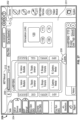
- FIG. 23 details of the test indicating the state of the NMP and the relative safety of continuing on with nerve testing are conveyed to the surgeon via GUI display 34.
- function specific data is displayed in a center result area 201.
- the results may be shown as a numeric value 210, a highlighted label corresponding to the electrode labels 86, or (in the case of twitch test only) a bar graph of the stimulation results.
- On one side of center result area 201 is a collapsible device menu 202.
- the device menu displays a graphic representation of each device connected to the patient module 14. Opposite the device menu 202 there is a collapsible test menu 204.
- the test menu 204 highlights each test that is available under the operable setup profile and may be used to navigate between functions.
- a collapsible stimulation bar 206 indicates the current stimulation status and provides start and stop stimulation buttons (not shown) to activate and control stimulation.
- the collapsible event bar 208 stores all the stimulation test results obtained throughout a procedure. Clicking on a particular event will open a note box and annotations may be entered and saved with the response for later inclusion in a procedure report.
- the event bar 208 also houses a chat box feature when the system 10 is connected to a remote monitoring system as described above. Within the result area 202 the twitch test specific results may be displayed.
- Fig. 23 depicts the monitoring screen 200 while the selected function is the Twitch Test
- the features of monitoring screen 200 apply equally to all the functions.
- Result-specific data is displayed in a center result area 201.
- a large color saturated numeric value (not shown) is used to show the threshold result.
- Three different options are provided for showing the stimulation response level. First, the user can view the waveform. Second, a likeness of the color coded electrode harness label 86 may be shown on the display. Third, the color coded label 212 may be integrated with a body image.
- On one side of center result area 201 there is a collapsible device menu 202. The device menu displays a graphic representation of each device connected to the patient module 14.
- an impedance test may be initiated. Opposite the device menu 202 there is a collapsible test menu 204.
- the test menu 204 highlights each test that is available under the operable setup profile and may be used to navigate between functions.
- a collapsible stimulation bar 206 indicates the current stimulation status and provides start and stop stimulation buttons (not shown) to activate and control stimulation.
- the collapsible event bar 208 stores all the stimulation test results obtained throughout a procedure so that the user may review the entire case history from the monitoring screen. Clicking on a particular event will open a note box and annotations may be entered and saved with the response for later inclusion in a procedure report chronicling all nerve monitoring functions conducted during the procedure as well as the results of nerve monitoring.
- the report may be printed immediately from one or more printers located in the operating room or copied to any of a variety of memory devices known in the prior art, such as, by way of example only, a floppy disk, and/or USB memory stick.
- the system 10 may generate either a full report or a summary report depending on the particular needs of the user.
- the identifiers used to identify the surgical accessories to the patient module may also be encoded to identify their lot number or other identifying information. As soon as the accessory is identified, the lot number may be automatically added to the report.
- hand held scanners can be provided and linked to the control unit 12 or patient module 14.
- the accessory packaging may be scanned and again the information may go directly to the procedure report.
- the event bar 208 also houses a chat box feature when the system 10 is connected to a remote monitoring system to allow a user in the operating room to contemporaneously communicate with a person performing the associated neuromonitoring in a remote location.
- the system 10 may also conduct free-run EMG monitoring while the system is in any of the modes described herein. Free-run EMG monitoring continuously listens for spontaneous muscle activity that might be indicative of potential danger. The system 10 may automatically cycle into free-run monitoring after 5 seconds of inactivity. Initiating a stimulation signal in the selected mode will interrupt the free-run monitoring until the system 10 has again been inactive for five seconds, at which time the free-run begins again.
- the system 10 may test the integrity of pedicle holes (during and/or after formation) and/or screws (during and/or after introduction) via the Basic Stimulation EMG and Dynamic Stimulation EMG tests.
- a test probe 116 is placed in the screw hole prior to screw insertion or placed on the installed screw head and a stimulation signal is applied.
- the insulating character of bone will prevent the stimulation current, up to a certain amplitude, from communicating with the nerve, thus resulting in a relatively high I thresh , as determined via the basic threshold hunting algorithm described below.
- the current density in the breach area will increase to the point that the stimulation current will pass through to the adjacent nerve roots and they will depolarize at a lower stimulation current, thus I thresh will be relatively low.
- the system described herein may exploit this knowledge to inform the practitioner of the current I thresh of the tested screw to determine if the pilot hole or screw has breached the pedicle wall.
- test probe 116 may be replaced with a clip 18 which may be utilized to couple a surgical tool, such as for example, a tap member 28 or a pedicle access needle 26, to the system 10.
- a surgical tool such as for example, a tap member 28 or a pedicle access needle 26, to the system 10.
- a stimulation signal may be passed through the surgical tool and pedicle integrity testing can be performed while the tool is in use.
- testing may be performed during pilot hole formation by coupling the access needle 26 to the system 10, and during pilot hole preparation by coupling the tap 28 to the system 10.
- a pedicle screw to the system 10 (such as via pedicle screw instrumentation)
- integrity testing may be performed during screw introduction.
- the signal characteristics used for testing in the lumbar testing may not be effective when monitoring in the thoracic and/or cervical levels because of the proximity of the spinal cord to thoracic and cervical pedicles.
- a breach formed in a pedicle of the lumbar spine results in stimulation being applied to a nerve root
- a breach in a thoracic or cervical pedicle may result in stimulation of the spinal cord instead, but the spinal cord may not respond to a stimulation signal the same way the nerve root would.
- the surgical system 10 is equipped to deliver stimulation signals having different characteristics based on the region selected.
- stimulation signals for the stimulated EMG modes comprise single pulse signals.
- the stimulation signals may be configured as multipulse signals.
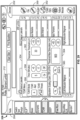
- Stimulation results (including but not necessarily limited to at least one of the numerical I thresh value and color coded safety level indication) and other relevant data are conveyed to the user on at least main display 34, as illustrated in Figs. 24 and 25 .
- Fig. 24 illustrates the monitoring screen 200 with the Basic Stimulation EMG test selected.
- Fig. 25 illustrates the monitoring screen 200 with the Dynamic Stimulation EMG test selected.
- green corresponds to a threshold range of greater than 10 milliamps (mA)
- a yellow corresponds to a stimulation threshold range of 7-10 mA
- a red corresponds to a stimulation threshold range of 6 mA or below.
- EMG channel tabs may be selected via the touch screen display 26 to show the F res h of the corresponding nerves. Additionally, the EMG channel possessing the lowest ' t h res h may be automatically highlighted and/or colored to clearly indicate this fact to the user.
- the system 10 may perform nerve proximity testing, via the XLIF mode, to ensure safe and reproducible access to surgical target sites.
- the system 10 detects the existence of neural structures before, during, and after the establishment of an operative corridor through (or near) any of a variety of tissues having such neural structures which, if contacted or impinged, may otherwise result in neural impairment for the patient.
- the surgical access components 26-32 are designed to bluntly dissect the tissue between the patient's skin and the surgical target site. Dilators of increasing diameter, which are equipped with one or more stimulating electrodes, are advanced towards the target site until a sufficient operating corridor is established to advance retractor 32 to the target site.
- the stimulation signal will stimulate nerves in close proximity to the stimulation electrode and the corresponding EMG response is monitored. As a nerve gets closer to the stimulation electrode, the stimulation current required to evoke a muscle response decreases because the resistance caused by human tissue will decrease, and it will take less current to cause nervous tissue to depolarize.
- ' t h res h is calculated, using the basic threshold hunting algorithm described below, providing a measure of the communication between the stimulation signal and the nerve and thus giving a relative indication of the proximity between access components and nerves.
- An example of the monitoring screen 200 with XLIF mode active is depicted in Fig. 26 .
- a green or safe level corresponds to a stimulation threshold range of 10 milliamps (mA) or greater, a yellow level denotes a stimulation threshold range of 5-9 mA, and a red level denotes a stimulation threshold range of 4 mA or below.
- MEP modes stimulation signals are delivered to the motor cortex via patient module 14 and resulting responses are detected from various muscles in the upper and lower extremities.
- An increase in I thresh from an earlier test to a later test may indicate a degradation of spinal cord function.
- the absence of a significant EMG response to a given I stim on a channel that had previously reported a significant response to the same or lesser I stim is also indicative of a degradation in spinal cord function.
- MEP Manual mode the user selects the stimulation current level and the system reports whether or not the stimulation signal evokes a significant response on each channel.
- Stimulation results may be shown on the display 34 in the form of "YES” and "NO" responses, or other equivalent indicia, as depicted in Fig. 27 .
- MEP Automatic mode the system determines the I thresh baseline for each channel corresponding to the various monitored muscles, preferably early in the procedure, using the multi-channel algorithm described. Throughout the procedure subsequent tests may be conducted to again determine I thresh for each channel. The difference between the resulting I thresh values and the corresponding baseline are computed by the system 10 and compared against predetermined "safe” and "unsafe" difference values.
- the I thresh , baseline and difference values are displayed to the user, along with any other indicia of the safety level determined (such as a red, yellow, green color code), on the display 34, as illustrated in Fig. 28 .
- the surgeon may thus be alerted to potential complications with the spinal cord and any corrective actions deemed necessary may be undertaken at the discretion of the surgeon.
- the system 10 is capable of ascertaining the health and/or status of at-risk nerves along the motor neural pathway superior and inferior to the surgical site before, during, and/or after the creation of the operative corridor to the surgical target site.
- stimulation electrodes 22 may be placed on the skin over the desired spinal nerve roots (such as by way of example only, the L1 and L2 nerve roots and/or the location of the conus medullaris of the patient) and recording electrodes 24 are positioned on the recording sites (such as, by way of example only, the recording sites set forth above in Table 5).
- the control unit 12 and patient module 14 cooperate to transmit electrical stimulation signals to a stimulating cathode placed posteriorly on the patient's back.
- stimulation signals cause nerves deep to the stimulating electrode to depolarize, evoking activity from muscles innervated by the nerves below.
- the system 10 detects and records the neuromuscular responses and optionally analyzes their relationship to the stimulation signal (discussed below). Resulting recording and/or assessment data is conveyed to the user on screen 200 and/or activator 330 as discussed herein.
- the TCNR testing described herein provides the ability to verify that the patient is positioned in a neutral way and that no neural structures have been impinged upon after the operative corridor has been established.
- system 10 may be particularly suited for establishing an operative corridor to an intervertebral target site in a posterolateral, trans-psoas fashion so as to avoid the bony posterior elements of the spinal column.
- a stimulating cathode is placed posteriorly and an anode is placed anteriorly at locations superior to the surgical target site and neuromuscular responses (transcutaneous nerve root "TCNR" responses) are evoked in response to transcutaneous, trans-abdominal motor pathway stimulation.
- the stimulating cathode may be a single cathode adhesive surface electrode placed over the conus medullaris at spinal level L1-2, preferably with the electrode pair oriented side to side and symmetrically over the neural foramen.
- the anode electrode may be an adhesive surface electrode placed at the anterior abdominal midline below the umbilicus, preferably with the electrode pair oriented side to side, symmetrically across the midline.
- a stimulation montage in this way is beneficial for at least two reasons.
- stimulating trans-abdominally does not evoke muscle twitching of the head, upper extremities, or upper torso which leads to less patient movement than transcranial MEP testing.
- using a surface electrode with a larger surface electrode anteriorly and a smaller surface electrode posteriorly may decrease the current density travelling trans-abdominally, reducing the depolarization of the abdominal muscles and thus, further decreasing the amount of patient movement.
- stimulating nerve roots with the TCNR techniques described herein can activate the specific area of the motor neural pathway of interest and elicit significant neuromuscular responses with a fixed polarity, single pulse stimulation whereas MEP testing requires multi-pulse trains of stimuli (oftentimes dual polarity stimulation as well) to activate the motor cortex and the entire corticospinal pathway to elicit clinically significant neuromuscular responses. This leads to greater specificity, less patient movement, and less power delivered to the patient.
- Recording electrodes may be placed on or in muscles innervated by one or more nerves of the lumbar plexus.
- the electrode harness 80 may be designed such that the various electrodes may be positioned about the patient as described in Table 5.
- the steps of performing transcutaneous, trans-abdominal stimulation and recording the resultant evoked potentials is preferably first performed prior to establishing the lateral access corridor and subsequently performed periodically during the surgical procedure.
- the system 10 is capable of detecting changes to the stimulation threshold intensities of these nerves over time which may be indicative of changes to the health/status of these nerves (e.g. by compression or patient positioning).
- the system 10 may perform TCNR in either of two modes: Alert mode and Threshold mode.
- Alert mode the system 10 evaluates the neuromuscular responses for the presence/absence of a response.
- Threshold mode the system 10 detects changes to the stimulus intensity required to elicit a significant response.
- a change in the health or status of a nerve may be deemed significant once the stimulus intensity required to elicit a neuromuscular response from a muscle exceeds pre-determined criteria (e.g. 200 A greater than the baseline stimulation threshold).
- the system 10 may quickly and accurately determine this data and convey the useful information in a simple and easily comprehensible manner for interpretation by a surgeon, neurophysiologist, or other medical personnel. It is contemplated that the control unit 12 of the system 10 may automatically ascertain this information and/or communicate any of numerical, graphic, audio, and visual feedback corresponding to one or more of these findings. Armed with this useful information, the surgeon may detect a problem or potential problem early and then act to avoid and/or mitigate the problem.
- pre-determined criteria e.g. 200 A greater than the baseline stimulation threshold
- Figs. 29-34 are example screen displays of the TCNR mode according to one example of the system 10.
- Fig. 29 illustrates an intraoperative monitoring (IOM) setup screen from which various features and parameters of the TCNR mode may be controlled and/or adjusted by the user as desired.
- IOM intraoperative monitoring
- the user may select the TCNR mode from the test selection tab 204.
- the user may plug the activator 330 into accessory port 133 as described above.
- the user may press stimulation button 340 on activator 330 which will automatically toggle the system 10 from the mode it was performing prior to TCNR mode selection to TCNR mode (e.g. XLIF mode).
- pressing stimulation button 340 in this manner 340 not only toggles the system 10 to TCNR mode, but also immediately initiates a TCNR stimulation test as well giving the user rapid flexibility in assessing the health and status of various aspects of the lower motor neural pathway.
- the devices tab 202 indicates to the user an activator icon 350 and a TCNR/EMG icon 350 indicating that the activator 330 and TCNR/EMG harness 80 are properly connected to the system 10.
- TCNR Menu window 354 The user may toggle between Alert mode and Threshold mode in TCNR Mode field 356, and change one or more profile settings (e.g. timer, waveform scaling, response threshold maximum stimulation).
- profile settings e.g. timer, waveform scaling, response threshold maximum stimulation.
- a user may wish to know when a predetermined period of time has elapsed between TCNR stimulations.
- a timer may be adjusted in timer field 358.
- the timer may be turned on or off and the time may be selected from a range between 0 and 30 minutes, with a default value of 5 minutes.
- the timer setting may be increased or decreased in increments of 5 minutes using the timer selection buttons labeled (by way of example only) "+5" and “-5".
- Waveform scaling may be accomplished by increasing or decreasing the gain by using the buttons labeled (by way of example only) "Zoom In” and "Zoom Out” in waveform scaling field 360.
- the gain has a range of 10 ⁇ V and 10,000 ⁇ V with a default gain setting is 200 ⁇ V. Each adjustment increases or decreases the gain by a fixed increment (e.g. 10 ⁇ V).
- the minimum threshold setting for which a given response qualifies as a response may be displayed and adjusted in response threshold field 362.
- the selected response threshold setting may be increased or decreased in increments of 10 ⁇ V using the buttons labeled "+10" and "-10".
- the threshold setting may be selected from a range of 10 ⁇ V to 300 ⁇ V with a default value of 30 ⁇ V.
- the maximum stimulation intensity that may be delivered in TCNR Threshold mode may also be selected in Threshold maximum stimulation field 364.
- the maximum threshold may be selected from a range between SOmA and 1500mA with a starting value of 100mA.
- the threshold setting may be increased or decreased in increments of 50A using buttons labeled (by way of example only) "+50" and "-50". As shown by way of example in Fig. 29 , the maximum threshold is shown at 900mA, that is to say the maximum threshold that may be delivered to the patient is 900mA.
- Figs. 30-31 depict example screen displays for the Alert mode of the TCNR monitoring function. These screen displays are intended to communicate information to the surgeon or other personnel in an easy-to-interpret fashion.
- This information may include, but is not necessarily limited to, a display of the test mode 212, channels 10 for each myotome [indicating]: spinal levels monitored (e.g. L. Add. Mag.); waveforms of the evoked responses, voltages of the evoked responses; a stimulation bar 206 to display particulars of the stimulation (e.g. stimulation parameters, the stimulation intensity required to elicit a response, and the stimulation intensity required to elicit a response.
- This information may be communicated in any number of suitable fashions, including but not limited to, the use of visual indicia (such as alpha-numeric characters, light-emitting elements, and/or graphics) and audio communication (such as a speaker element).
- TCNR Alert mode the underlying neurophysiologic principle of operation is to assess the health and status of the lower motor neural pathway via the presence/absence of evoked neuromuscular responses for each muscle monitored.
- the user first manually selects the stimulation intensity to be delivered to the stimulation electrodes.
- the stimulation intensity that may be delivered in TCNR Alert mode may also be selected in Alert stimulation field 366.
- the simulation intensity may be selected from a range between 50mA and 1500mA with a starting value of 100mA.
- the setting may be increased or decreased in increments of 50mA with a starting value of 100mA.
- the setting may be increased or decreased in increments of 50mA using buttons labeled (by way of example only) "+50" and "-50".
- the stimulation intensity to be delivered is 500mA.
- the system 10 provides visual and audible alerts when the responses are absent.
- the system 10 may flash a warning on screen 200, or an audible tone.
- TCNR Alert mode periodic testing for the presence/absence of TCNR responses are made to monitor the health and status of the lower motor neural pathways.
- a user may which to know when a predetermined period of time has elapsed between TCNR tests. Armed with such information, the user may perform another TCNR test or wait until a later time in the surgical procedure to do so.
- the timer interval may be set as described above. After each TCNR test, the system 10 will initiate a timer corresponding to the selected time interval and, when the time has elapsed, the system 10 will activate a reminder alert.
- the reminder alert may include, by way of example only, any one of, or combination of, an audible tone, voice recording, screen flash, pop up window, scrolling message, or any other such alert to remind the user to perform a TCNR test again.
- the alerts may be displayed on screen 200 (for example, in the stimulation bar), on the activator (for example via LED indicator 342), or both screen 200 and activator 330 simultaneously.
- the TCNR stimulations are preferably conducted at a set time interval throughout the surgical procedure (e.g., every 5 minutes).
- the LED indicator 342 and/or the on-screen stimulator bar 206 blinks green at a 1Hz rate
- the user may decide to perform another TCNR test either by pressing button 340 or "Start Stim" button 370 or the user may decide to wait until a later time in the surgical procedure.
- LED indicator 342 (and/or the on-screen stimulator bar 206) continues to blink green but at a 2Hz rate.
- the timer function may be implemented in TCNR Threshold mode as well.
- Figs. 32-34 depict example screen displays for the Threshold mode of the TCNR monitoring function.
- TCNR Threshold mode the underlying neurophysiologic principle is that, in order to monitor the health of the lumbar motor neural pathway, the user must be able to determine if the evoked responses are changing with respect to the stimulation signal. To monitor for this change, baseline TCNR responses are established for all muscles of interest (preferably prior to surgical manipulation) and then compared to subsequent TCNR responses periodically throughout the procedure.
- the baseline feature of the TCNR Threshold mode will now be described with respect to Fig. 32 .
- Selecting the "Find Baseline" button 368 on the screen 200 or pressing the stimulation button 340 on the activator 330 starts the baseline stimulation sequence.
- the system 10 then delivers one or more stimulation pulses and/or trains of pulses until a baseline TCNR response is evoked in one or all muscle channels.
- the system 10 may be configured to determine the stimulus response threshold (I t h res h) via one or more of the threshold hunting and thresholding algorithms described below.
- baseline TCNR responses and baseline response thresholds (Inuesh-Base) were found in all 10 muscle channels (shown for each channel as 200mA in results field 372).
- baseline TCNR response waveforms remain in the waveform windows for comparison to subsequent stimulation trials. This allows for more detailed comparison of the response waveform amplitudes and morphologies.
- the peak to peak amplitude measurements (in microvolts) of both the baseline and subsequent results are displayed in the waveform window.
- the baseline waveforms and subsequent waveforms bay be indicated differently, by way of example the baseline waveform may be depicted as purple and the current waveform may be depicted as white.
- the associated window may preferably be highlighted with a predetermined color (e.g. red) to indicate the potential danger to the surgeon.
- a predetermined color e.g. red
- the stimulation results are displayed to the surgeon along with a color code so that he/she may easily comprehend the danger, diagnose, and take corrective measures to avoid or mitigate such danger. This may, for example, more readily permit TCNR monitoring results to be interpreted by the surgeon or assistant without necessarily requiring dedicated monitoring personnel.
- red is used when the increase in threshold stimulus intensity is within a predetermined safe level.
- Yellow is used when the increase in threshold stimulus intensity is between the predetermined safe and unsafe levels.
- the system 10 may also notify the user of potential danger through the use of a warning which may be communicated to the user by any one of, or combination of, a pop-up window, an audible tone, voice recording, screen flash, scrolling message, or any other such alert to notify the user of potential danger.
- the system 10 may notify the user according to the following scenario: Table 9: Change in 'Thresh from Baseline Color Audio Feedback Neurophysiologic Assessment 0-100mA Green Slow, Low Pitch No significant change from baseline > 100mA to ⁇ 200mA Yellow Faster, Higher Pitch Noteworthy change from baseline 200mA or more Red Fastest, Highest Pitch Significant change from baseline
- Figs. 33-34 depict example TCNR responses obtained subsequent to the baseline TCNR responses of Fig. 32 .
- the baseline I thresh response results move from results field 372 to baseline field 374.
- responses in a subsequent test were obtained in all channels 110 with 200mA stimulation (I thresh-subsequent ), indicating no significant changes in neurophysiologic recordings from baseline. These results are displayed in results field 372.
- green color indicators shown for each of these channels in accordance with the example shown and described above in Table 9.
- the system 10 includes functionality to toggle or switch between two or more neurophysiologic monitoring modes quickly and seamlessly as will be discussed below.
- the control unit 12 possesses the requisite functionality to toggle or switch between XLIF and TCNR modes as directed by the user.
- the toggling or switching is effectuated by the stimulation clip 18/activator 330 assembly described above.
- the system 10 will stay in XLIF mode until an indication from the user. This indication may be pressing the stimulation button 340 on the activator 330.
- Pressing the stimulation button 340 one time will simultaneously toggle to the appropriate TCNR mode screen and perform a stimulation trial in TCNR mode.
- the user may press activation button 131 on button module 129 to simultaneously toggle to the XLIF mode screen and perform a stimulation trial in XLIF mode or, if a stimulation trial in XLIF mode is not desired at that time, the user can do nothing.
- the TCNR screen may time out (for example, 1 minute after the last TCNR stimulation trial) and the system 10 will toggle or switch back to the XLIF mode screen 200.
- the TCNR timer function will still be active and will remind the user to perform another stimulation when the timer has lapsed as set forth above.
- the user is able to perform more than one neurophysiologic monitoring modes intermittently without having to does not need to make/or instruct hospital personnel to make changes on the screen 200 to switch between modes.
- stimulation signals are delivered to peripheral sensory electrodes placed over the desired peripheral nerve (such as, by way of example only, the Posterior Tibial nerve and/or the Ulnar nerve) and recording electrodes 23 are positioned on or over the recording sites (such as, by way of example only, over the C2 vertebra, scalp, Erb's Point, and Popliteal Fossa), and stimulation signals are delivered from the patient module14. Damage in the spinal cord may disrupt the transmission of the signal up the spinal cord resulting in a weakened or delayed signal at the recording site.
- the signal response waveforms and latency values associated with those waveforms are displayed for the user.
- the system 10 compares the difference between the amplitude and latency of the signal response vs. the amplitude and latency of a baseline signal response. These differences are compared against the predetermined "safe” and “unsafe” levels and the results are displayed on display 34. The results are displayed to the user along with any other indicia of the safety level determined (such as a red, yellow, green color code), on the display 34, as illustrated in Fig. 36 ).
- the system 10 may employ one or more algorithms to quickly select the optimal stimulus parameters for conducting SSEP testing on each active stimulation channel. This can be done according to any number of algorithms that automatically adjust various parameters until a combination resulting in the most desirable result is achieved.
- the system 10 aids the user in planning and assessing the degree to which he/she has achieved the surgical goals during a spinal procedure.
- Fig. 37 there may be included a feature in which the system 10 is capable of digitizing implanted screw positions, outputting bend instructions for a rod, and previewing the shape of the rod on screen 200.
- the rod bending instructions are for a rod shaped to custom-fit within the implanted screw locations.
- the system 10 is further capable of accepting correction inputs via one or more advanced option features for viewing bend instructions for a rod shaped to fit at locations apart from those implanted screw locations.
- Installing a rod shaped in this manner could correct a curvature deformity in the patient's spine according to a user's prescribed surgical plan.
- restoring a patient's spine to a balanced position may be a desired surgical outcome.
- the system 10 is configured to receive and assess 1) preoperative spinal parameter inputs; 2) target spinal parameter inputs; 3) intraoperative spinal parameter inputs; and/or postoperative spine parameter inputs via screen 200.
- Spinal parameters may comprise the patient's Pelvic Incidence (PI), Pelvic Tilt (PT), Sacral Slope (SS), Lumbar Lordosis (LL), Superior Lumbar Lordosis (I'LL), Inferior Lumbar Lordosis (ILL), C7 Plumb Line Offset (C7PL), Thoracic Kyphosis (TK), T1 Tilt, and Sagittal, Vertical Axis (SVA) measurements.
- PI Pelvic Incidence
- PT Pelvic Tilt
- LL Lumbar Lordosis
- I'LL Superior Lumbar Lordosis
- ILL Inferior Lumbar Lordosis
- C7 Plumb Line Offset C7 Plumb Line Offset
- TK Thoracic Kyphosis
- T1 Tilt and Sagittal, Vertical Axis (SVA) measurements.
- PI Pelvic Incidence
- PT Pelvic Tilt
- SS Sacral Slope
- LL Lumbar Lordosis
- the system 10 identifies and measures the peak-to-peak voltage (V pp ) of each EMG response corresponding to a given stimulation current (I stim .). Identifying the true vpp of a response may be complicated by the existence of stimulation and/or noise artifacts which may create an erroneous vpp measurement. To overcome this challenge, the system 10 of the present invention may employ any number of suitable artifact rejection techniques such as those shown and described in full in the above referenced co-pending and commonly assigned PCT App. Ser. No. PCT/US2004/025550, entitled “System and Methods for Performing Dynamic Pedicle Integrity Assessments," filed on August 5, 2004 .
- the V pp information is analyzed relative to the corresponding stimulation current (I stim ) in order to identify the minimum stimulation current (I Thresh ) capable of resulting in a predetermined vpp EMG response.
- I Thresh the minimum stimulation current capable of resulting in a predetermined vpp EMG response.
- the determination of I Thresh may be accomplished via any of a variety of suitable algorithms or techniques.
- Figs. 39 A-D illustrate, by way of example only, the principles of a threshold hunting algorithm of the present invention used to quickly find Ithresh.
- the method for finding I thresh utilizes a bracketing method and a bisection method.
- the bracketing method quickly finds a range (bracket) of stimulation currents that must contain I Thresh and the bisection method narrows the bracket until I I Thresh is known within a specified accuracy. If the stimulation current threshold, I Thresh , of a channel exceeds a maximum stimulation current, that threshold is considered out of range.
- Figs. 39 A-D illustrate the bracketing feature of the threshold hunting algorithm of the present invention.
- Stimulation begins at a minimum stimulation current, such as (by way of example only) lmA. It will be appreciated that the relevant current values depend in part on the function performed (e.g. high currents are used for MEP and low currents are generally used for other functions) and the current values described here are for purposes of example only and may in actuality be adjusted to any scale.
- the level of each subsequent stimulation is doubled from the preceding stimulation level until a stimulation current recruits (i.e. results in an EMG response with a vpp greater or equal to V thresh ).
- the first stimulation current to recruit (8 mA in Fig. 39 B) together with the last stimulation current to have not recruited (4 mA in Fig. 39 B) , forms the initial bracket.
- Figs. 39 C-D illustrate the bisection feature of the threshold hunting algorithm of the present invention.
- the initial bracket is successively reduced via bisection to a predetermined width, such as (by way of example only) 0.25 mA. This is accomplished by applying a first bisection stimulation current that bisects (i.e. forms the midpoint of) the initial bracket (6 mA in Fig. 39 C) . If this first bisection stimulation current recruits, the bracket is reduced to the lower half of the initial bracket (e.g. 4 mA and 6 mA in Fig. 39 C) .
- this first bisection stimulation current does not recruit, the bracket is reduced to the upper half of the initial bracket (e.g. 6 mA and 8 mA in Fig, 39 C) .
- This process is continued for each successive bracket until I thresh is bracketed by stimulation currents separated by the predetermined width (which, in this case, is 0.25 mA). In this example shown, this would be accomplished by applying a second bisection stimulation current (forming the midpoint of the second bracket, or 5 mA in this example). Because this second bisection stimulation current is below Mesh, it will not recruit. As such, the second bracket will be reduced to the upper half thereof (5 mA to 6 mA), forming a third bracket.
- a third bisection stimulation current forming the mid-point of the third bracket (5.50 mA in this case) will then be applied. Because this third bisection stimulation current is below I thresh , it will not recruit. As such, the third bracket will be reduced to the upper half thereof (5.50 mA to 6 mA), forming a fourth bracket. A fourth bisection stimulation current forming the mid-point of the fourth bracket (5.75 mA in this case) will then be applied. Because the fourth bisection stimulation current is above I thresh , it will recruit. The final bracket is therefore between 5.50mA and 5.75 mA.
- I thresh Due to the "response" or recruitment at 5.50 mA and “no response” or lack of recruitment at 5.75 mA, it can be inferred that I thresh is within this range. In one example, the midpoint of this final bracket may be defined as I thresh , however, any value falling within the final bracket may be selected as I thresh without departing from the scope of the present invention.
- the algorithm may stop after finding Mesh for the first responding channel (i.e. the channel with the lowest I thresh) or the bracketing and bisection steps may be repeated for each channel to determine I thresh for each channel. In one example, this multiple channel I thresh determination may be accomplished by employing the additional steps of the multi-channel threshold detection algorithm, described below.
- the system may continuously update the stimulation threshold level and indicate that level to the user.
- the threshold hunting algorithm does not repeatedly determine the I thresh level anew, but rather, it determines whether stimulation current thresholds are changing. This is accomplished, as illustrated in Fig. 39 D , by a monitoring phase that involves switching between stimulations at lower and upper ends of the final bracket. If the threshold has not changed then the lower stimulation current should not evoke a response, while the upper end of the bracket should. If either of these conditions fail, the bracket is adjusted accordingly. The process is repeated for each of the active channels to continue to assure that each threshold is bracketed.
- the algorithm transitions back to the bracketing state in order to reestablish the bracket.
- the user may be alerted immediately via the screen display and/or audio feedback.
- the color shown on the display corresponding to the previous ' t h res h can be altered to a neutral color (e.g. black, grey, etc%) as soon as the change in ' I thresh is detected but before the new 'thresh value is determined, If an audio tone is used to represent a particular safety level, the tone can ceased as soon as the change in detected. Once the new thresh value is determined the color and/or audio tone can be altered again to signify the value.
- the threshold hunting algorithm may begin by immediately determining the appropriate safety level and then entering the bracketing phase.
- the algorithm may accomplish this by initiating stimulation at one or more of the boundary current levels.
- the algorithm may begin by delivering a stimulation signal at the boundary between the unsafe (e.g. red) and caution (e.g. yellow) levels. If the safety level is not apparent after the first stimulation, the algorithm may stimulate again at the boundary between the caution (e.g. yellow) and safe (e.g. green) levels. Once the safety level is known (i.e.
- the screen display may be updated to the appropriate color and/or coded audio signals may be emitted.
- the algorithm may transition to the bracketing and bisection phases to determine the actual 'thresh value.
- the display may be updated again to reflect the additional information.
- the algorithm will again stimulate at the boundary level(s) as necessary and update the color and/or audio signals before transitioning to the bracketing and bisection phases to determine the new I thresh .
- I I thresh For some functions, such as (by way of example) MEP, it may be desirable to obtain I I thresh for each active channel each time the function is performed. This is particularly advantageous when assessing changes in 'thresh over time as a means to detect potential problems (as opposed to detecting an I thresh below a predetermined level determined to be safe, such as in the Stimulated EMG modes). While I thresh can be found for each active channel using the algorithm as described above, it requires a potentially large number of stimulations, each of which is associated with a specific time delay, which can add significantly to the response time. Done repeatedly, it could also add significantly to the overall time required to complete the surgical procedure, which may present added risk to the patient and added costs. To overcome this drawback, an example of the system 10 boasts a multi-channel threshold hunting algorithm so as to quickly determine I thresh for each channel while minimizing the number of stimulations and thus reduce the time required to perform such determinations.
- the multi-channel threshold hunting algorithm reduces the number stimulations required to complete the bracketing and bisection steps when I thresh is being found for multiple channels.
- the multi-channel algorithm does so by omitting stimulations for which the result is predictable from the data already acquired. When a stimulation signal is omitted, the algorithm proceeds as if the stimulation had taken place. However, instead of reporting an actual recruitment result, the reported result is inferred from previous data. This permits the algorithm to proceed to the next step immediately, without the time delay associated with a stimulation signal.
- each stimulation signal elicits a response from all active channels. That is to say, every channel either recruits or does not recruit in response to a stimulation signal (again, a channel is said to have recruited if a stimulation signal evokes an EMG response deemed to be significant on that channel, such as vpp of approximately 100 uV). These recruitment results are recorded and saved for each channel.
- the saved data can be accessed and, based on that data, the algorithm may omit a stimulation signal and infer whether or not the channel would recruit at the given stimulation current.
- a stimulation signal may be omitted if the selected stimulation current would be a repeat of a previous stimulation.
- the algorithm may omit the stimulation and report the previous results. If the specific stimulation current required has not previously been used, a stimulation signal may still be omitted if the results are already clear from the previous data.
- the algorithm may infer from the previous stimulation that the present channel will not recruit at 1mA because it did not recruit at 2mA. The algorithm may therefore omit the stimulation and report the previous result.
- Fig. 41 illustrates (in flowchart form) a method by which the multi-channel threshold hunting algorithm determines whether to stimulate, or not stimulate and simply report previous results.
- the algorithm first determines if the selected stimulation current has already been used (step 302). If the stimulation current has been used, the stimulation is omitted and the results of the previous stimulation are reported for the present channel (step 304). If the stimulation current has not been used, the algorithm determines I recruit (step 306) and I norecruit (step 308) for the present channel. I recruit is the lowest stimulation current that has recruited on the present channel. I norecruit is the highest stimulation current that has failed to recruit on the present channel. The algorithm next determines whether I recruit is greater than I norecruit (step 310).
- I recruit that is not greater than I norecruit is an indication that changes have occurred to I thresh on that channel. Thus, previous results may not be reflective of the present threshold state and the algorithm will not use them to infer the response to a given stimulation current.
- the algorithm will stimulate at the selected current and report the results for the present channel (step 312). If I recruit is greater than I norecruit , the algorithm determines whether the selected stimulation current is higher than I recruit , lower than I norecruit , or between I recruit and I norecruit (step 314). If the selected stimulation current is higher than I recruit , the algorithm omits the stimulation and reports that the present channel recruits at the specified current (step 316).
- the algorithm infers that the present channel will not recruit at the selected current and reports that result (step 318). If the selected stimulation current falls between recruit and Inorecruit, the result of the stimulation cannot be inferred and the algorithm stimulates at the selected current and reports the results for the present channel (step 312). This method may be repeated until Ithresh has been determined for every active channel.
- Figs. 42 A-C demonstrate use of the multi-channel threshold hunting algorithm to determine Ithresh on only two channels. It should be appreciated, however, that the multi-channel algorithm is not limited to finding th res h for two channels, but rather it may be used to find Ithresh for any number of channels, such as (for example) eight channels.
- channel 1 has an Ithresh to be found of 6.25 mA and channel 2 has an Ithresh to be found of 4.25 mA. Ithresh for channel 1 is found first as illustrated in Fig. 38 B, using the bracketing and bisection methods discussed above.
- Bracketing begins at the minimum stimulation current (for the purposes of example only) of 1 mA, As this is the first channel processed and no previous recruitment results exist, no stimulations are omitted.
- the stimulation current is doubled with each successive stimulation until a significant EMG response is evoked at 8 mA.
- the initial bracket of 4-8 mA is bisected, using the bisection method described above, until the stimulation threshold, I thresh , is contained within a final bracket separated by the selected width or resolution (again .25 mA). In this example, the final bracket is 6 mA-6.25 mA.
- I thresh may be defined as any point within the final bracket or as the midpoint of the final bracket (6.125 mA in this case). In either event, I thresh is selected and reported as I thresh for channel 1.
- the algorithm turns to channel 2, as illustrated in Fig. 42 C .
- the algorithm begins to process channel 2 by determining the initial bracket, which is again 4-8 mA. All the stimulation currents required in the bracketing state were used in determining Ithresh for channel 1.
- the algorithm refers back to the saved data to determine how channel 1 responded to the previous stimulations. From the saved data, the algorithm may infer that channel 2 will not recruit at stimulation currents of 1, 2, and 4 mA, and will recruit at 8 mA. These stimulations are omitted and the inferred results are displayed.
- the first bisection stimulation current selected in the bisection process (6 mA in this case), was previously used and, as such, the algorithm may omit the stimulation and report that channel 2 recruits at that stimulation current.
- the next bisection stimulation current selected (5 mA in this case) has not been previously used and, as such, the algorithm must determine whether the result of a stimulation at 5 mA may still be inferred.
- I recruit and I norecruit are determined to be 6 mA and 4 mA, respectively. Because 5 mA falls in between I recruit and I norecruit , the algorithm may not infer the result from the previous data and, as such, the stimulation may not be omitted.
- the algorithm then stimulates at 5 mA and reports that the channel recruits.
- the bracket is reduced to the lower half (making 4.50 mA the next bisection stimulation current).
- a stimulation current of 4.5 mA has not previously been used and, as such, the algorithm again determines I recruit and I norecruit (5 mA and 4 mA in this case).
- the selected stimulation current (4.5 mA) falls in between I recruit an I norecruit and, as such, the algorithm stimulates at 4.5 mA and reports the results.
- the bracket now stands at its final width of .25 mA (for the purposes of example only).
- I thresh may be defined as any point within the final bracket or as the midpoint of the final bracket (4.125 mA in this case). In either event, I thresh is selected and reported as I thresh for channel 2.
- the multi-channel threshold hunting algorithm is described above as processing channels in numerical order, it will be understood that the actual order in which channels are processed is immaterial.
- the channel processing order may be biased to yield the highest or lowest threshold first (discussed below) or an arbitrary processing order may be used.
- the algorithm may cycle between one or more channels, processing as few as one stimulation current for that channel before moving on to the next channel.
- the algorithm may stimulate at 10mA while processing a first channel for I thresh .
- the algorithm Before stimulating at 20 mA (the next stimulation current in the bracketing phase), the algorithm may cycle to any other channel and process it for the 10 mA stimulation current (omitting the stimulation if applicable). Any or all of the channels may be processed this way before returning to the first channel to apply the next stimulation. Likewise, the algorithm need not return to the first channel to stimulate at 20 mA, but instead may select a different channel to process first at the 20 mA level. In this manner, the algorithm may advance all channels essentially together and bias the order to find the lower threshold channels first or the higher threshold channels first. By way of example only, the algorithm may stimulate at one current level and process each channel in turn at that level before advancing to the next stimulation current level.
- the algorithm may continue in this pattern until the channel with the lowest I thresh is bracketed.
- the algorithm may then process that channel exclusively until I thresh is determined, and then return to processing the other channels one stimulation current level at a time until the channel with the next lowest I thresh is bracketed. This process may be repeated until I thresh is determined for each channel in order of lowest to highest I thresh . If I thresh for more than one channel falls within the same bracket, the bracket may be bisected, processing each channel within that bracket in turn until it becomes clear which one has the lowest I thresh . If it becomes more advantageous to determine the highest I thresh first, the algorithm may continue in the bracketing state until the bracket is found for every channel and then bisect each channel in descending order.
- Figs. 43 A-B illustrates a further feature of the threshold hunting algorithm of the present invention, which advantageously provides the ability to further reduce the number of stimulations required to find I thresh when an I thresh value has previously been determined for a specific channel.
- the algorithm may begin by merely confirming the previous I thresh rather than beginning anew with the bracketing and bisection methods. The algorithm first determines whether it is conducting the initial threshold determination for the channel or whether there is a previous I thresh determination (step 320). If it is not the initial determination, the algorithm confirms the previous determination (step 322) as described below.
- the algorithm reports that value as the present I thresh (step 324). If it is the initial I thresh determination, or if the previous threshold cannot be confirmed, then the algorithm performs the bracketing function (step 326) and bisection function (step 328) to determine I thresh and then reports the value (step 324).
- the hunting algorithm is discussed herein in terms of finding I thresh (the lowest stimulation current that evokes a predetermined EMG response), it is contemplated that alternative stimulation thresholds may be useful in assessing the health of the spinal cord or nerve monitoring functions and may be determined by the hunting algorithm.
- the hunting algorithm may be employed by the system 10 to determine a stimulation voltage threshold. This is the lowest stimulation voltage necessary to evoke a significant EMG response. Bracketing, bisection and monitoring states are conducted as described above for each active channel, with brackets based on voltage being substituted for the current based brackets previously described.
- the algorithms described herein may also be used for determining the stimulation threshold (current or voltage) for any other EMG related functions, including but not limited to pedicle integrity (screw test), nerve detection, and nerve root retraction.
- Figs. 44 A-B depict, by way of example only, the principles of a focused linear thresholding algorithm of the present invention used to quickly elicit a significant evoked neuromuscular response.
- the method for finding the evoked neuromuscular response utilizes a baseline ramping method and a subsequent ramping method to find I thresh .
- the baseline ramping method quickly finds stimulation intensity that generates a significant evoked neuromuscular response in each channel within a specified accuracy.
- the subsequent ramping method uses the baseline ramping results to find the minimum stimulation current threshold intensity that generates a significant neuromuscular response in each channel within a specified accuracy.
- the baseline linear ramping method quickly finds a minimum stimulation intensity that generates responses by increasing I stim in a linear fashion until I thresh is known within a specified accuracy for each channel.
- Stimulation begins at a starting stimulation current, such as (by way of example only) 100mA (step 376).
- a starting stimulation current such as (by way of example only) 100mA (step 376).
- the relevant current values depend in part on the function performed (e.g. high currents are used for TCNR and MEP and low currents are generally used for other functions) and the current values described here are for purposes of example only and may in actuality be adjusted to any scale.
- the algorithm will increment each stimulation [level] from the preceding stimulation level by a fixed amount (e.g. 50mA) until a stimulation level recruits a baseline neuromuscular response (I thresh-baseline ) for each channel (step 382).
- the lowest stimulation level to recruit a baseline neuromuscular response in at least one channel is saved for recall in the subsequent focused linear ramping algorithm (step 378).
- baseline I thresh values for all channels have been defined, the results are reported (step 380) to the control unit 12.
- the baseline linear ramping method includes the optional step of switching the polarity of stimulation at each stimulation intensity level and reporting the results of I thresh and the associated polarity at step 380.
- the focused linear thresholding algorithm includes a subsequent focused ramping method so as to quickly determine I thresh for each channel while minimizing the total number of stimulations, lowering the total energy delivered, and reducing the time required to perform such determinations.
- the subsequent focused linear ramping method may reduce the number of stimulations required to find I thresh during subsequent stimulations after baseline, particularly when I thresh is being found for multiple channels.
- the algorithm does so by omitting stimulations for which the result is predictable from the baseline data already acquired. This permits the algorithm to proceed to the next step immediately, without the time delay associated with an unnecessary stimulation signal.
- the algorithm may then quickly find I thresh-subsequent by using the lowest I thresh-baseline (i.e. threshold stimulus intensity of the first channel to recruit at baseline) and increasing the stimulus intensity in a linear fashion until I thresh-subsequent is known within a specified accuracy for each channel.
- the algorithm confirms the lowest baseline I thresh to recruit a response in at least one channel by stimulating at that I stim (step 376). In those implementations including a switching of polarity, the algorithm confirms the baseline at polarity in which the lowest I thresh was obtained. If the I stim at step 376 results in a response in all channels, the sequence stops and the results are reported to the control unit 12 (step 380). If the I stim at step 380 does not result in a response in all channels, the stimulation is increased a predetermined amount (step 382) and the sequence is repeated until a response is repeated in each channel. Once subsequent I thresh values for all channels have been defined, the results are reported (step 380) to the control unit 12.
- the focused linear thresholding algorithm is discussed herein in terms of finding I thresh (the lowest threshold stimulation intensity that evokes a predetermined EMG response), it is contemplated that alternative thresholds may be useful in assessing the health of the lumbar motor neural pathways, spinal cord, or nerve monitoring functions and may be determined by the algorithm.
- the algorithm may be employed by the system 10 do determined a stimulation voltage threshold Vstim thresh . This is the lowest stimulation voltage (as opposed to the lowest stimulation current) necessary to evoke a significant EMG response, V thresh .
- each neurophysiologic testing mode may include its own optimized stimulation profile, such that the term “stimulation” may comprise multiple meanings.
- TCNR stimulation may be a single pulse, such that the term “stimulation” may refer to a single pulse of stimulation energy whereas MEP stimulation may be a train of three to eight stimulation pulses such that the term “stimulation” may refer to a multiple train stimulation.
- a method for monitoring the status of the motor neural pathway that includes the steps of: (a) stimulating the motor pathways in a transcutaneous and trans-abdominal fashion from a location superior (caudal, above) to the surgical site; (b) recording neurophysiologic responses evoked by that transcutaneous, trans-abdominal stimulation from one or more locations inferior (caudal, below) to the surgical site; and (c) comparing evoked responses over time to assess the health and status of the lower motor neural pathway.
- This particular method is useful in lumbar (as well as thoracic and thoracolumbar) spinal surgeries, where motor function may be at risk, to monitor and verify lumbar motor neural function throughout the procedure.
- the present invention may be implemented using any combination of computer programming software, firmware or hardware.
- the computer programming code (whether software or firmware) according to the invention will typically be stored in one or more machine readable storage mediums such as fixed (hard) drives, diskettes, optical disks, magnetic tape, semiconductor memories such as ROMs, PROMs, etc., thereby making an article of manufacture in accordance with the invention.
- the article of manufacture containing the computer programming code is used by either executing the code directly from the storage device, by copying the code from the storage device into another storage device such as a hard disk, RAM, etc. or by transmitting the code on a network for remote execution.
- a hard disk such as a hard disk, RAM, etc.
- transcutaneous, trans-abdominal nerve root stimulation method described herein may be used in conjunction with the monitoring method described above during surgical access with a surgical access system.
Landscapes
- Health & Medical Sciences (AREA)
- Life Sciences & Earth Sciences (AREA)
- Surgery (AREA)
- Veterinary Medicine (AREA)
- Neurology (AREA)
- Biomedical Technology (AREA)
- Heart & Thoracic Surgery (AREA)
- Animal Behavior & Ethology (AREA)
- General Health & Medical Sciences (AREA)
- Public Health (AREA)
- Engineering & Computer Science (AREA)
- Medical Informatics (AREA)
- Molecular Biology (AREA)
- Physics & Mathematics (AREA)
- Biophysics (AREA)
- Pathology (AREA)
- Neurosurgery (AREA)
- Nuclear Medicine, Radiotherapy & Molecular Imaging (AREA)
- Physiology (AREA)
- Orthopedic Medicine & Surgery (AREA)
- Measurement And Recording Of Electrical Phenomena And Electrical Characteristics Of The Living Body (AREA)
- Electrotherapy Devices (AREA)
- Surgical Instruments (AREA)
- Measuring And Recording Apparatus For Diagnosis (AREA)
- Radiology & Medical Imaging (AREA)
Description
- The present invention relates to a system generally aimed at surgery. More particularly, the present invention is directed at a system for performing neurophysiologic assessments during surgical procedures.
- The spinal column is a highly complex system of bones and connective tissues that provide support for the body and protect the delicate spinal cord and nerves. The spinal column includes a series of vertebral bodies stacked one atop the other, each vertebral body including an inner or central portion of relatively weak cancellous bone and an outer portion of relatively strong cortical bone. Situated between each vertebral body is an intervertebral disc that cushions and dampens compressive forces exerted upon the spinal column. A vertebral canal containing the spinal cord is located behind the vertebral bodies.
- There are many types of spinal column disorders including scoliosis (abnormal lateral curvature of the spine), excess kyphosis (abnormal forward curvature of the spine), excess lordosis (abnormal backward curvature of the spine), spondylolisthesis (forward displacement of one vertebra over another), and other disorders caused by abnormalities, disease or trauma, such as ruptured or slipped discs, degenerative disc disease, fractured vertebrae, and the like. Patients that suffer from such conditions usually experience extreme and debilitating pain as well as diminished nerve function.
- A noteworthy trend in the medical community is the move away from performing surgery via traditional "open" techniques in favor of minimally invasive or minimal access techniques. Open surgical techniques are generally undesirable in that they typically require large incisions and high amounts of tissue displacement to gain access to the surgical target site, which produces concomitantly high amounts of pain, lengthened hospitalization (increasing health care costs), and high morbidity in the patient population. Less-invasive surgical techniques are gaining favor due to the fact that they involve accessing the surgical target site via incisions of substantially smaller size with greatly reduced tissue displacement requirements. This, in turn, reduces the pain, morbidity, and cost associated with such procedures. One such minimally invasive approach, a lateral trans-psoas approach to the spine, developed by NuVasive®, Inc., San Diego, CA (XLIF®) has demonstrated great success in reducing patient morbidity, shortening the duration of hospitalization, and speeding recovery time if it is employed.
- To create the lateral access corridor to the lumbar spine, the patient is positioned on his or her spine and a surgical access system is advanced through an incision, into the retroperitoneal space, and then through the psoas muscle until the target spinal site (for example, a disc space between a pair of adjacent vertebral bodies) is reached. The surgical access system may include a sequential dilation assembly of increasing diameter and a tissue retraction assembly. The sequential dilation assembly is advanced to the surgical target site and the retractor assembly is then advanced to the target site over the sequential dilation system. Stimulating electrodes may be provided on the distal tip of one or more different components of the surgical access system. Neurophysiologic monitoring may be performed while advancing one or more components of the dilation and retraction assemblies to the target site to detect the presence of, and thereby avoid, nerves lying in the trans-psoas path to the target site.
- Once the retractor assembly has been docked at a target site however, a nerve may become compromised due to a variety of factors including, but not limited to, compression of the nerve due to inadvertent contact with the retractor blade and patient positioning on the surgical table. Stimulating within the surgical site provides information regarding the health and status of nearby nerves within the surgical site during maintenance of the lateral access corridor. However, the portion of a nerve that is compressed or otherwise affected may not lie within the surgical site such that information regarding the health and status of a greater portion of the motor neural pathway is desirable. Other methods of stimulating the motor neural pathway (e.g., transcranial electric motor evoked potential monitoring (MEP)) use multi-pulse trains of stimuli with high stimulus intensities and depolarize all nerves along the corticospinal pathway and result in muscle activity of many muscles of the head, upper extremities, torso, and lower extremities. This whole-body stimulation can sometimes lead to large amounts of patient movement during the procedure. It is generally preferable to conduct neurophysiologic monitoring with the least amount of stimulation intensity (and patient movement) as possible. MEP monitoring is also disadvantageous for monitoring the lower motor neural pathway in that requires the use of total intravenous anesthesia (TIVA). TIVA requires close monitoring and is also more expensive than other anesthetic regimens. Furthermore, information regarding each specific nerve root is also desirable because it provides specific information regarding the health and/or status of each nerve root comprising the lumbar plexus. Therefore, a need exists for systems and methods of performing neurophysiologic monitoring on a greater portion of the motor neural pathway, lower amounts of stimulation intensity, shorter pulses, well-received anesthetic requirements, greater specificity of the at-risk nerve roots and earlier indications of potential post-operative complications such that mitigating actions may be taken.
- The present invention provides a non-transitory computer-readable medium for monitoring the health of the lower motor neural pathway during a spinal procedure, as set out in
claim 1. - The present disclosure includes systems and methods to evaluate the health and status of the lower motor neural pathway before, during and after the establishment of an operative corridor through (or near) any of a variety of tissues having such neural structures which, if contacted or impinged, may otherwise result in neural impairment for the patient. It is expressly noted that, although described herein largely in terms of use in lateral lumbar spinal surgery, the system and methods of the present disclosure are suitable for use in any number of additional spinal surgeries including posterior, posterolateral, anterior, anterolateral lumbar spinal surgeries as well as thoracic and thoracolumbar spinal surgeries. Indeed, the present disclosure is suitable for use in any number of additional surgical procedures wherein tissue having significant neural structures must be passed through (or near) in order to establish an operative corridor.
- According to another broad aspect, the present disclosure includes a control unit, a patient module, and a plurality of surgical accessories adapted to couple to the patient module. The control unit includes a power supply and is programmed to receive user commands, activate stimulation in a plurality of predetermined modes, process signal data according to defined algorithms, display received parameters and processed data, and monitor system status. The patient module is in communication with the control unit. The patient module is within the sterile field. The patient module includes signal conditioning circuitry, stimulator drive circuitry, and signal conditioning circuitry required to perform said stimulation in said predetermined modes. The patient module includes a processor programmed to perform a plurality of predetermined functions including at least two of neuromuscular pathway assessment, non-evoked monitoring, static pedicle integrity testing, dynamic pedicle integrity testing, nerve proximity detection, manual motor evoked potential monitoring, automatic motor evoked potential monitoring, transcutaneous nerve root testing, manual somatosensory evoked potential monitoring, automatic somatosensory evoked potential monitoring, and surgical correction planning and assessment.
- According to still another broad aspect, the present disclosure includes a processing unit programmed to perform a plurality of predetermined functions using said instrument including at least two of neuromuscular pathway assessment, static pedicle integrity testing, dynamic pedicle integrity testing, nerve proximity detection, transcutaneous nerve root testing, non-evoked monitoring, motor evoked potential monitoring, somatosensory evoked potential monitoring, and surgical correction planning and assessment. The processing system has a pre-established profile for at least one of said predetermined functions so as to facilitate the initiation of said at least one predetermined function.
- According to another broad aspect of the present disclosure, there is provided a method for performing transcutaneous, trans-abdominal stimulation of the lumbar motor neural pathways superior and inferior to a surgical target site.
- Many advantages of the present invention will be apparent to those skilled in the art with a reading of this specification in conjunction with the attached drawings, wherein like reference numerals are applied to like elements and wherein:
-
Figure 1 is a block diagram of an example neurophysiologic monitoring system capable of conducting multiple nerve and spinal cord monitoring functions including but not necessarily limited to neuromuscular pathway, bone integrity, nerve detection, nerve pathology (evoked or free-run EMG), lower motor pathway, MEP, and SSEP assessments; -
Fig. 2 is a perspective view showing examples of several components of the system ofFig. 1 ; -
Fig. 3 is a graph illustrating a plot of a single pulse stimulation current signal capable of producing a neuromuscular response (EMG) of the type shown inFig. 5 ; -
Fig. 4 is a graph illustrating [a] plot of a stimulation current signal comprising a train of pulses capable of producing a neuromuscular response (EMG) of the type shown inFig. 5 ; -
Fig. 5 is a graph illustrating a plot of the neuromuscular response of a given myotome over time based on a stimulation signal (such as shown in either Fit. 4 ofFig. 5 ); -
Fig. 6 is a perspective view of an example of a control unit forming part of the system ofFig. 1 ; -
Figs. 7-9 are perspective, top, and side views, respectively, of an example of a patient module forming part of the system ofFig. 1 ; -
Fig. 10 is a top view of an electrode harness forming part of the system ofFig. 1 ; -
Figs. 11A-11C are side views of various examples of harness ports forming part of the system ofFig. 1 ; -
Fig. 12 is a plan view of an example of a label affixed to an electrode connector forming part of the system ofFig. 1 ; -
Figs. 13A-13B are top views of examples of electrode caps forming part of the system ofFig. 1 ; -
Figs. 14A-14B are screenshots of an example of an electrode test screen forming part of the system ofFig. 1 ; -
Fig. 15 is a perspective view of a stimulator forming part of the system ofFig. 1 ; -
Fig. 16 is a perspective view of a second stimulator forming part of the system ofFig. 1 ; -
Fig. 17 is a perspective view of the stimulators ofFig. 15 and 16 coupled together for use; -
Figs. 18A-18B are perspective views third and fourth stimulators forming part of the system ofFig. 1 ; -
Fig. 19 is a perspective view of the stimulators ofFig. 18A and16 coupled together for use; -
Figs. 20-21 are perspective views of an example of a secondary display forming part of the system ofFig. 1 ; -
Fig. 21 is a first screenshot of an example of a TCNR Alert monitoring screen forming part of the neurophysiology system ofFig. 1 ; -
Fig. 22 is a screenshot of an example of a profile screen forming part of the system ofFig. 1 ; -
Fig. 23 is a screenshot of an example of a Twitch Test monitoring screen forming part of the system ofFig. 1 ; -
Fig. 24 is a screenshot of an example of a Basic Stimulation EMG monitoring screen forming part of the system ofFig. 1 ; -
Fig. 25 is a screenshot of an example of a Dynamic Stimulation EMG monitoring screen forming part of the system ofFig. 1 ; -
Fig. 26 is a screenshot of an example of a Nerve Surveillance EMG monitoring screen forming part of the system ofFig. 1 ; -
Fig. 27 is a screenshot of an example of a Manual MEP monitoring screen forming part of the system ofFig. 1 ; -
Fig. 28 is a screenshot of an example of an Automatic MEP monitoring screen forming part of the system ofFig. 1 ; -
Fig. 29 is a screenshot of an example of a TCNR setup screen forming part of the system ofFig. 1 ; -
Fig. 30 is a first screenshot of an example of a TCNR Alert monitoring screen forming part of the system ofFig. 1 ; -
Fig. 31 is a second screenshot of the TCNR Alert monitoring screen ofFig. 30 ; -
Fig. 32 is a first screenshot of an example of a TCNR Threshold monitoring screen forming part of the system ofFig. 1 ; -
Fig. 33 is a second screenshot of the TCNR Threshold monitoring screen ofFig. 32 ; -
Fig. 34 is a third screenshot of the TCNR Threshold monitoring screen ofFig. 32 ; -
Fig. 35 is a screenshot of an example of an SSEP Manual monitoring screen forming part of the system ofFig. 1 ; -
Fig. 36 is a screenshot of an example of an SSEP Automatic monitoring screen form part of the system ofFig. 1 ; -
Fig. 37 is a screenshot of an example of a first surgical correction planning and assessment screen forming part of the system ofFig. 1 ; -
Fig. 38 is a screenshot of an example of second surgical correction planning and assessment screen forming part of the system ofFig. 1 ; -
Figs. 39A-D are graphs illustrating the fundamental steps of a rapid current threshold-hunting algorithm; -
Fig. 40 is a block diagram illustrating the steps of an initiation sequence for determining a relevant safety level prior to determining a precise threshold value according to an alternate threshold hunting algorithm ofFigs. 39A-D ; -
Fig. 41 is a flowchart illustrating the method by which a multi-channel hunting algorithm determines whether to perform or omit a stimulation; -
Figs. 42A-C are graphs illustrating use of the threshold hunting algorithm ofFig. 41 and further omitting stimulations when the likely result is already clear from previous data; -
Fig. 43A is a flowchart illustrating the sequence employed by the algorithm to determine and monitor Ithresh; -
Fig. 43B is a graph illustrating the confirmation step employed by the algorithm to determine whether Ithresh has changed from a previous determination; and -
Fig. 44 is a flowchart illustrating the sequence of a rapid thresholding algorithm . - Illustrative embodiments of the invention are described below. In the interest of clarity, not all features of an actual implementation are described in this specification. It will of course be appreciated that in the development of any such actual embodiment, numerous implementation-specific decisions must be made to achieve the developers' specific goals, such as compliance with system-related and business-related constraints, which will vary from one implementation to another. Moreover, it will be appreciated that such a development effort might be complex and time-consuming, but would nevertheless be a routine undertaking for those of ordinary skill in the art having the benefit of this disclosure. The systems disclosed herein boast a variety of inventive features and components that warrant patent protection, both individually and in combination. It is also expressly noted that, although described herein largely in terms of use in lateral surgery in the lumbar spine, the system and methods of the present disclosure may also be employed in any number of other spine surgery procedures including posterior, poster-lateral, anterior, and anterolateral lumbar, thoracic, and/or cervical spine procedures, all without departing from the present disclosure. The systems and methods described herein boast a variety of inventive features and components that warrant patent protection, both individually and in combination.
- A
neurophysiologic monitoring system 10 is described herein and is capable of performing a number of neurophysiological and/or guidance assessments at the direction of the surgeon (and/or other members of the surgical team). By way of example only,Figs. 1-2 illustrate the basic components of thesystem 10. The system comprises a control unit 12 (including amain display 34 preferably equipped with a graphical user interface (GUI) and aprocessing unit 36 that collectively contain the essential processing capabilities for controlling the system 10), apatient module 14, a stimulation accessory (e.g. astimulation probe 16,stimulation clip 18 for connection to various surgical instruments, an inline stimulation hub 20, and stimulation electrodes 22), and a plurality ofrecording electrodes 24 for detecting electrical potentials. - The stimulation accessories may be in the form of various prove devices that are themselves inserted into the stimulation site, clips that attach and deliver stimulation signals to standard instruments that are used at various times throughout a procedure...and surface electrodes. The
stimulation clip 18 may be used to connect any of a variety of surgical instruments to thesystem 10, including, but not necessarily limited to apedicle access needle 26, k-wire 27,tap 28, dilator(s) 30,tissue retractor 32, etc. One or more secondary feedback devices (e.g.secondary display 46 inFig. 20-21 ) may also be provided for additional expression of output to a user and/or receiving input from the user. - The
system 10 may be configured to execute any of the functional modes including, but not necessarily limited to, neuromuscular pathway assessment ("Twitch Test"), non-evoked monitoring ("Free-run EMG"), static pedicle integrity testing ("Basic Stimulated EMG"), dynamic pedicle integrity testing ("Dynamic Stimulated EMG"), nerve proximity detection ("XLIF®"), motor evoked potential monitoring ("MEP Manual" and "MEP Automatic"), transcutaneous nerve root testing ("TCNR Alert" and "TCNR Threshold"), somatosensory evoked potential monitoring ("SSEP Manual" and "SSEP Automatic"), and surgical correction planning and assessment. Thesystem 10 may also be configured for performance in any of the lumbar, thoracolumbar, and cervical regions of the spine. - The basis for performing many of these functional modes (e.g. Twitch Test, Basic Stimulated EMG, Dynamic Stimulated EMG, XILF, MEP Manual, MEP Automatic, TCNR Alert, and TCNR Threshold) is the assessment of evoked responses of the various muscles myotomes monitored by the
system 10 in relation to a stimulation signal transmitted by the system 10 (via patient module 14). The assessment of the evoked responses can be any suitable means of sensing physical motion of a muscle, for example via mechanomyography (MMG) which entails using an accelerometer or other similar device for detecting mechanical movement of a muscle or via electromyography (EMG) which is described in detail herein. This is illustrated inFigs. 3-5 , whereinFig. 5 illustrates the resulting EMG waveform of a monitored myotome in response to one of the example stimulation signals represented inFig. 3 and Fig. 4 . The EMG responses provide a quantitative measure of the nerve depolarization caused by the electrical stimulus. One way to characterize the EMG response is by a peak-to-peak voltage of Vpf,,Vmax-Vmhi, as shown inFig. 5 . Nerve tissues have characteristic threshold current levels (thresh) at which they will depolarize and result in a detectable muscle activity. Below this threshold current level, a stimulation signal will not evoke a significant EMG response. A significant EMG response may be defined as having a vpp of approximately 100uV. Thus, the lowest stimulation current necessary to evoke an EMG response of the threshold voltage (Vthresh), 100uV in this example, may be called hresh. The greater the degree of electrical communication between a stimulation signal and a nerve, the lower 'thresh will be. Conversely, the lower the degree of electrical communication between a stimulation signal and a nerve, the greater Mesh will be. Thus determining Ith,,sh, and/or monitoring changes in 'thresh over time, may provide valuable information when nerve tissues are at risk during a surgical procedure, as will be discussed in more detail below. By way of example, an excessively high Ithresh or an increase over a previous measurement during MEP testing may indicate a problem in the spinal cord or other portion of the motor pathway inhibiting transmission (communication) of the stimulation signal to the nerve. Meanwhile, during the Basic Stimulated EMG or Dynamic Stimulated EMG modes and the XLIF mode, a low 'thresh value may indicate a breach in the pedicle allowing the electrical signal to transmit through the pedicle, or the close proximity of a nerve to the stimulation source, respectively. Armed with the useful information conveyed by thresh, the surgeon may detect a problem or potential problem early and then act to avoid and/or mitigate the problem. Theneurophysiology system 10 may quickly and accurately determine Ithresh under the direction and operation of the surgeon (if desired) and convey the useful information Ithresh contains in a simple and easily comprehensible manner for interpretation by the surgeon. - Before further addressing the various functional modes of the
surgical system 10, the hardware components and features of thesystem 10 will be describe in further detail. Thecontrol unit 12 of thesystem 10, illustrated by way of example only inFig. 6 , includes amain display 34 and aprocessing unit 36, which collectively contain the essential processing capabilities for controlling thesystem 10. Themain display 34 is preferably equipped with a graphical user interface (GUI) capable of graphically communicating information to the user and receiving instructions from the user. Theprocessing unit 36 contains computer hardware and software that commands the stimulation source (e.g.patient module 14,Figs. 7-9 ), receives digital and/or analog signals and other information from thepatient module 14, processes EMG and SSEP response signals, and displays the processed data to the user via thedisplay 34. The primary functions of the software within thecontrol unit 12 include receiving user commands via the touch screenmain display 34, activating stimulation in the appropriate mode (Twitch Test, Basic Stimulated EMG, Dynamic Stimulated EMG, XLIF, MEP Manual, MEP Automatic, TCNR Alert, TCNR Threshold, SSEP Manual, and SSEP Automatic), processing signal data according to defined algorithms, displaying received parameters and processed data, and monitoring system status. Themain display 34 may comprise a 15" LCD display equipped with suitable touch screen technology and theprocessing unit 36 may comprise a 2GHz. Theprocessing unit 36 shown inFig. 6 further includes apowered USB port 38 for connection to thepatient module 14, a media drive 40 (e.g. CD, CD-RW, DVD, DVD-RW, etc...), a network port, wireless network card, and a plurality of additional ports 42 (e.g. USB, IEEE 1394, infrared, etc...) for attaching additional accessories, such as for example only, navigated guidance sensors, auxiliary stimulation anodes, and external devices (e.g. printer, keyboard, mouse, etc...). Preferably, during use thecontrol unit 12 sits near the surgical table but outside the surgical field, such as for example, on a table top or a mobile stand. It will be appreciated, however, that if properly draped and protected, thecontrol unit 12 may be located within the surgical (sterile) field. - The
patient module 14, shown by way of example only inFigs. 4-6 , is communicatively linked to thecontrol unit 12. Thepatient module 14 is communicatively linked with and receives power from thecontrol unit 12 via aUSB data cable 44. However, it will be appreciated that thepatient module 14 may be supplied with its own power source and other known data cables, as well as wireless technology, may be utilized to establish communication between thepatient module 14 andcontrol unit 12. Thepatient module 14 contains a digital communications interface to communicate with thecontrol unit 12, as well as the electrical connections to all recording and stimulation electrodes, signal conditioning circuitry, stimulator drive and steering circuitry, and signal conditioning circuitry required to perform all of the functional modes of thesystem 10, including but not necessarily limited to Twitch Test, Free-run EMG, Basic Stimulated EMG, Dynamic Stimulated EMG, XLIF, MEP Manual and MEP Automatic, TCNR Alert, TCNR Threshold, SSEP Manual, and SSEP Automatic. In one example, thepatient module 14 includes thirty-two recording channels and eleven stimulation channels. A display (e.g. an LCD screen) may be provided on the face of thepatient module 14, and may be utilized for showing simple status readouts (for example, results of a power on test, the electrode harnesses attached, and impedance data, etc...) or more procedure related data (for example, a stimulation threshold result, current stimulation level, selected function, etc...). Thepatient module 14 may be positioned near the patient in the sterile field during surgery. By way of example, thepatient module 14 may be attached to bed rail with the aid of ahook 48 attached to, or forming a part of, thepatient module 14 casing. - With reference to
Figs. 7-9 ,patient module 14 comprises a multitude of ports and indicators for connecting and verifying connections between thepatient module 14 and other system components. Acontrol unit port 50 is provided for data and power communication with thecontrol unit 12, viaUSB data cable 44 as previously described. There are fouraccessory ports 52 provided for connecting up to the same number of surgical accessories, including, but not necessarily limited to,stimulation probe 16,stimulation clip 18, inline stimulation hub 20, and navigated guidance sensor (or tilt sensor) 54. Theaccessory ports 52 include a stimulation cathode and transmit digital communication signals, tri-color LED drive signals, button status signals, identification signals, and power between thepatient module 14 and the attached accessory. A pair ofanode ports 56, preferably comprising 2 wire DIN connectors, may be used to attach auxiliary stimulation anodes should it become desirable or necessary to do so during a procedure. A pair ofUSB ports 58 are connected as a USB hub to thecontrol unit 12 and may be used to make any number of connections, such as for example only, a portable storage drive. - As soon as a device is plugged into any one of
ports system 10 automatically performs a circuit continuity check to ensure the associated device will work properly. Each device forms a separate closed circuit with the patient module such that the devices may be checked independent of each other. If one device is not working properly the device may be identified individually while the remaining devices continue indicate their valid status. An indicator LED is provided for each port to convey the results of the continuity check to the user. Thus, according to the example ofFigs. 7-9 , thepatient module 14 includes onecontrol unit indicator 60, fouraccessory indicators 62, twoanode indicators 64, and twoUSB indicators 66. If the system detects an incomplete circuit during the continuity check, the appropriate indicator will turn red alerting the user that the device might not work properly. On the other hand, if a complete circuit is detected, the indicator will appear green signifying that the device should work as desired. Additional indicator LEDs are provided to indicate the status of the system and the MEP stimulation. Thesystem indicator 68 will appear green when the system is ready and red when the system is not ready. TheMEP stim indicator 70 lights up when the patient module is ready to deliver and MEP stimulation signal. TheMEP stim indicator 68 appears yellow to indicate a ready status. - To connect the array of
recording electrodes 24 andstimulation electrodes 22 utilized by thesystem 10, thepatient module 14 also includes a plurality of electrode harness ports. Thepatient module 14 includes an EMG/MEP harness port 72,SSEP harness port 74, an Auxiliary harness port 76 (for expansion and/or custom harnesses; e.g, a TCNR harness). Eachharness port socket 78 that corresponds to a matching shapedconnector 82 on theappropriate electrode harness 80. In addition, thesystem 10 may preferably employ a color code system wherein each modality (e.g. EMG, EMG/MEP, and SSEP) has a unique color associated with it. By way of example only and as shown herein, EMG monitoring (including, screw tests, detection, and nerve retractor) may be-associated with the color green, MEP monitoring with the color blue, and SSEP monitoring may be associated with the color orange. Thus, eachharness port appropriate harness 80. Utilizing the combination of the dedicated color code and the shaped socket connector interface simplifies the setup of the system, reduces errors, and can greatly minimize the amount of pre-operative preparation necessary. Thepatient module 14, and especially the configuration of quantity and layout of the various ports and indicators, has been described according to one example . It should be appreciated, however, that thepatient module 14 could be configured with any number of different arrangements without departing from the scope of the invention. - As mentioned above, to simplify setup of the
system 10, all of therecording electrodes 24 andstimulation electrodes 22 that are required to perform one of the various functional modes (including acommon electrode 23 providing a ground reference to pre-amplifiers in thepatient module 14, and ananode electrode 25 providing a return path for the stimulation current) are bundled together and provided insingle electrode harness 80, as illustrated, by way of example only, inFig. 10 . Depending on the desired function or functions to be used during a particular procedure, different groupings ofrecoding electrodes 24 andstimulation electrodes 22 may be required. By way of example, the SSEP function requires morestimulating electrodes 22 than either the EMG or MEP functions, but also requires fewer recording electrodes than either of the EMG and MEP functions. To account for the differing electrode needs of the various functional modes, thesystem 10 may employdifferent harnesses 80 tailored for the desired modes. Three different electrode harnesses 80 may be provided for use with thesystem 10, an EMG harness, an EMG/MEP harness, and an SSEP harness. - At one end of the
harness 80 is the shapedconnector 82. As described above, the shapedconnector 82 interfaces with the shapedsocket harness 80 utilizes a shapedconnector 82 that corresponds to the appropriate shapedsocket patient module 14. If the shapes of the socket and connector do not match theharness 80, connection to thepatient module 14 cannot be established. The EMG and the EMG/MEP harnesses both plug into the EMG/MEP harness port 72 and thus they both utilize the same shapedconnector 82. By way of example only,Figs. 11A-11C illustrate the various shape profiles used by thedifferent harness ports connectors 82.Fig. 11A illustrates the half circular shape associated with the EMG and EMG/MEP harness andport 72.Fig. 11B illustrates the rectangular shape utilized by the SSEP harness andport 74. Finally,Fig. 11C illustrates the triangular shape utilized by the Auxiliary harness andport 76. Eachharness connector 82 includes a digital identification signal that identifies the type ofharness 80 to thepatient module 14. At the opposite end of theelectrode harness 80 are a plurality ofelectrode connectors 102 linked to theharness connector 82 via a wire lead. Using theelectrode connector 102, any of a variety of known electrodes may be used, such as by way of example only, surface dry gel electrodes, surface wet gel electrodes, and needle electrodes. - To facilitate easy placement of scalp electrodes used during MEP and SSEP modes, an
electrode cap 81, depicted by way of example only inFig. 13A may be used. Theelectrode cap 81 includes tworecording electrodes 23 for SSEP monitoring, twostimulation electrodes 22 for MEP stimulation delivery, and ananode 23. Graphic indicators may be used on theelectrode cap 81 to delineate the different electrodes. By way of example, lightning bolts may be used to indicate a stimulation electrode, a circle within a circle may be used to indicate recording electrodes, and a stepped arrow may be used to indicate the anode electrode. The anode electrode wire is colored white to further distinguish it from the other electrodes and is significantly longer that the other electrode wires to allow placement of the anode electrode on the patient's shoulder. The shape of theelectrode cap 81 may also be designed to simplify placement. By way of example only, thecap 81 has a pointed end that may point directly toward the patient's nose when thecap 81 is centered on the head in the right orientation. A single wire may connect theelectrode cap 81 to thepatient module 14 orelectrode harness 80, thereby decreasing the wire population around the upper regions of the patient. Alternatively, thecap 81 may be equipped with a power supply and a wireless antenna for communicating with thesystem 10.Fig. 13B illustrates another example of anelectrode cap 83 similar to cap 81. Rather than using graphic indicators to differentiate the electrodes, colored wires may be employed. By way of example, thestimulation electrodes 22 are colored yellow, therecording electrodes 24 are gray, and theanode electrode 23 is white. The anode electrode is seen here configured for placement on the patient's forehead. Alternatively, the electrode cap (not shown) may comprise a strap or set of straps configured to be worn on the head of the patient. The appropriate scalp recording and stimulation sites may be indicated on the straps. By way of example, the electrode cap may be imbued with holes overlying each of the scalp recording sites (for SSEP) and scalp stimulation sites (for MEP). According to a further example, the border around each hole may be color coded to match the color of an electrode lead wire designated for that site. In this instance, the recording and stimulation electrodes designated for the scalp are preferably one of a needle electrode and a corkscrew electrode that can be placed in the scalp through the holes in the cap. - As will be explained in greater detail below, the electrodes of different sizes and configurations may be preferable for the TCNR mode than for MEP, EMG, and SSEP modes. According to some implementations, the posterior cathode is a single use cathode electrode that has a circular shape (radially symmetric) to simplify positioning (superficially on the dorsal midline, approximately over the conus medullaris at the L1-L2 spinal level). The full contact surface is a conductive adhesive hydrogel to eliminate the need for skin prep. The connecting lead is made of insulated radiolucent carbon wire to avoid obscuring fluoroscopic images. The terminating 1.5mm female DIN connector is color coded purple to maintain correct polarity corresponding with the mating harness connector. The anterior anode is a single use anode electrode has a square shape (radially symmetric) with a relatively large surface area to simplify positioning (superficially on the abdominal midline below the umbilicus) and increase the positioning location tolerance. The full contact surface is a conductive adhesive hydrogel to eliminate the need for skin prep. The connecting lead is made of insulated radiolucent carbon wire to avoid obscuring fluoroscopic images. The terminating 1.5mm female DIN connector is color coded yellow maintain correct polarity corresponding with the mating harness connector.
- In addition to or instead of color coding the electrode lead wires to designated intended placement, the end of each wire lead next to the
electrode connector 102 may be tagged with alabel 86 that shows or describes the proper positioning of the electrode on the patient. Thelabel 86 preferably demonstrates proper electrode placement graphically and textually. As shown inFig. 12 , the label may include a graphic image showing therelevant body portion 88 and theprecise electrode position 90. Textually, thelabel 86 may indicate theside 100 and muscle (or anatomic location) 96 for placement, the function of the electrode (e.g. stimulation, recording channel, anode, and reference - not shown), the patient surface (e.g. anterior or posterior), thespinal region 94, and the type of monitoring 92 (e.g. EMG, MEP, SSEP, by way of example, only). According to one example, the electrode harnesses 80 are designed such that the various electrodes may be positioned about the patient (and preferably labeled accordingly) as described in Table 1 for Lumbar EMG, Table 2 for Cervical EMG, Table 3 for Lumbar/Thoracolumbar EMG and MEP, Table 4 for Cervical EMG and MEP, Table 5 for TCNR, and Table 6 for SSEP:Table 1: Lumbar EMG Electrode Type Electrode Placement Spinal Level Ground Upper Outer Thigh Anode Latissimus Dorsi Stimulation Knee Recording Left Tibialis Anterior IA, L5 Recording Left Gastroc. Medialis Si, S2 Recording Left Vastus Medialis L2, L3, IA Recording Left Biceps Femoris L5, Si, S2 Recording Right Biceps Femoris L5, Si, S2 Recording Right Vastus Medialis L2, L3, IA Recording Right Gastroc. Medialis Si, S2 Recording Right Tibialis Anterior IA, L5 Table 2: Cervical EMG Electrode Type Electrode Placement Spinal Level Ground Shoulder Anode Mastoid Stimulation Inside Elbow - Recording Left Triceps C7, C8 Recording Left Flexor Carpi Radial i s C6, C7, C8 Recording Left Deltoid C5, C6 Recording Left Trapezius C3, C4 Recording Left Vocal Cord RLN Recording Right Vocal Cord RLN Recording Right Trapezius C3, C4 Recording Right Deltoid C5, C6 Recording Right Flexor Carpi Radialis C6, C7, C8 Recording Right Triceps C7, C8 Table 3: Lumbar/Thoracolumbar EMG + MEP Electrode Type Electrode Placement Spinal Level Ground Upper Outer Thigh - Anode Latissimus Dorsi - Stimulation Knee - Recording Left Tibialis Anterior L4, L5 Recording Left Gastroc. Medialis S1, S2 Recording Left Vastus Medialis L2, L3, L4 Recording Left Biceps Femoris L5, S1,S2 Recording Left APB-ADM C6, C7, C8, T1 Recording Right APB-ADM C6, C7, C8, T1 Recording Right Biceps Femoris L5, S1, S2 Recording Right Vastus Medialis L2, L3, L4 Recording Right Gastroc. Medialis S1, S2 Recording Right Tibialis Anterior L4, L5 Table 4: Cervical EMG + MEP Electrode Type Electrode Placement Spinal Level Ground Shoulder - Anode Mastoid - Stimulation Inside Elbow - Recording Left Tibialis Anterior L4, L5 Recording Left Flexor Carpi Radialis C6, C7, C8 Recording Left Deltoid C5, C6 Recording Left Trapezius C3, C4 Recording Left APB-ADM C6, C7, C8, T1 Recording Left Vocal Cord RLN Recording Right Vocal Cord RLN Recording Right APB-ADM C6, C7, C8, T1 Recording Right Trapezius C3, C4 Recording Right Deltoid C5, C6 Recording Right Flexor Carpi Radialis C6, C7, C8 Recording Right Tibialis Anterior L4, L5 Table 5: Transcutaneous Nerve Root Stimulation Electrode Type Electrode Placement Spinal Level Ground Hip - Anode Mid-back - Stimulation L1-L2 cathode - Stimulation Umbilicus anode - Recording Left Adductor Magnus L2, L3, L4 Recording Left Vastus Lateralis L3, L4 Recording Left Tibialis Anterior L4, L5 Recording Left Biceps Femoris L5, S1, S2 Recording Right Adductor Magnus L2, L3, L4 Recording Right Vastus Lateralis L3, L4 Recording Right Vastus Medialis L2, L3, L4 Recording Right Tibialis Anterior L4, L5 Recording Right Biceps Femoris L5, S1, S2 Table 6: SSEP Electrode Type Electrode Placement Spinal Level Ground Shoulder - Stimulation Left Post Tibial Nerve - Stimulation Left Ulnar Nerve - Stimulation Right Post Tibial Nerve - Stimulation Right Ulnar Nerve - Recording Left Popliteal Fossa - Recording Left Erb's Point - Recording Left Scalp Cp3 - Recording Right Popliteal Fossa - Recording Right Erb's Point - Recording Right Scalp Cp4 - Recording Center Scalp Fpz - Recording Center Scalp Cz - Recording Center Cervical Spine - - The
patient module 14 is configured such that thesystem 10 may conduct an impedance test under the direction of thecontrol unit 12 of all electrodes once the system is set up and the electrode harness is connected and applied to the patient. After choosing the appropriate spinal site upon program startup (described below), the user is directed to an electrode test.Figs. 14A-14B illustrate, by way of example only, a graphical implementation capturing the features of an electrode test[s] as implemented on anelectrode test screen 104. Theelectrode test screen 104 includes a human figure depiction with positionedelectrodes 108. Aharness indicator 109 displays which harness is in use. For each electrode on theharness 80 in use there is achannel button 110. This includes the common 25 andanode 23 electrodes which are both independently checked for impedance. To accomplish this, theanode 23 and common 25 are both provided as dual electrodes. At least one of the anode leads on the anode electrode is reversible. During the impedance check, the reversible anode lead switches to a cathode such that the impedance between the leads can be measured. When the impedance test is complete, the reversible lead switches back to an anode. Thechannel button 110 may be labeled with the muscle or coverage area of the corresponding electrode. Selecting thechannel button 110 will disable the channel. - Disabled channels will not be tested for impedance and they will not be monitored for responses or errors unless reactivated. Upon selection of a start button 106 ("Run Electrode Test"), the system tests each electrode individually to determine the impedance value. If the impedance is determined to be within acceptable limits, the
channel button 110 and electrode depiction on the human figure 108 turn green. If the impedance value for any electrode is not determined to be acceptable, the associatedchannel button 110 and electrode depiction turn red, alerting the user. Once the test is complete, selecting the "Accept"button 112 will open themain monitoring screen 200 of thesystem 10. - The
system 10 may utilize various stimulation accessories to deliver stimulation signals to a stimulation target site such as over the patient's conus medullaris, a hole formed or being formed in a pedicle, and/or tissue surrounding an access corridor.Figs. 15-17 illustrate an example of a stimulation accessory in the form of astimulation clip 18 that permits thesystem 10 to deliver stimulation signals through various surgical instruments already used during the surgical procedure. By way of example only, thecoupling device 18 may connect thesystem 10 with instruments including, but not necessarily limited to, apedicle access needle 26, atap 28,dilator 30,tissue retractor 32, and k-wire 27. Thestimulation clip 18 utilizes a spring-loadedplunger 128 to hold the surgical tool and transmit the stimulation signal thereto. Theplunger 128 is composed of a conductive material such as metal. Anonconductive housing 130 partially encases theplunger 128 about its center. Extending from thehousing 130 is anendplate 132 that hooks the surgical instrument. A spring (not shown) is disposed within thehousing 130 such that in a natural or "closed" state, theplunger 128 is situated in close proximity to theendplate 132. Exerting a compressive force on the spring (such as by pulling on the thumb grip 134) causes a gap between theend plate 132 and theplunger 128 to widen to an "open" position (shown inFigs. 15-17 thereby allowing insertion of a surgical tool between theendplate 132 andplunger 128. Releasing thethumb grip 134 allows the spring to return to a "closed" position, causing theplunger 132 to move laterally back towards the endplate such that a force is exerted upon the surgical instrument and thereby holding it in place between theendplate 132 and theplunger 128. Theclip 18 further includes abutton module 129 containing anactivation button 131 for initiating stimulation. Thebutton module 129 is set apart from the body of theclip 18 and they are linked by an integrated wire. Anaccessory port 133 is located next to thebutton 131 on thebutton module 129, thus minimizing the number of wires connecting back to thepatient module 14 and outside the sterile field.Clip 18 is equipped with threeLEDs LED 135 is associated with theaccessory port 133 andLED 137 is associated with theclip 18 to indicate which of the two is stimulating. TheLEDs LED third LED 139 is contained within thethumb grip 134, which will appear red, yellow, or green depending on the threshold result. Theclip 18 connects to one of theaccessory ports 62 on thepatient module 14 via aconnector 136. Theconnector 136 includes an identification signal that identifies it to the patient module. -
Fig. 18A illustrates a second example of a stimulation accessory in the form of an in-field activator 330. Theactivator 330 is preferably a single-use sterile device and may be designed [as] a stand-alone device designed to interface with thepatient module 14 independently or may be part of an assembly as will be explained below. Theactivator 330 may plug into anaccessory port 133 of thestimulation clip 18 ofFigs. 15-17 above to provide user control and status indication of the TCNR mode from inside the sterile field during the surgical procedure.Fig. 19 shows theactivator 330 plugged intoaccessory port 133 for in-field use. It is contemplated that theactivator 330 is compatible withmodule 129 such that theactivator 330 andclip 18 may be jointly connected to thesystem 10 viamodule 129 without the need for additional components, additional wires, and the like. Theactivator 330 includes a top 331, a bottom 332, a housing 333, afirst end 334, asecond end 336, aconnection plug 338 emanating from saidfirst end 334, astimulation button 334 and amulticolor LED indicator 342 disposed between ends 334, 336. Theconnection plug 338 is sized and dimensioned to fit within theaccessory port 133.Activator 330 may include one or more securing clips 348 (Fig. 18B ) for securing theactivator 330 to a surgical implement, such as, for example, an articulating arm or a retractor (not shown). Theactivator 330/stimulation clip 18 assembly may be connected to one of theaccessory ports 62 on thepatient module 14 via aconnector 136. Theconnector 136 includes an identification signal that identifies it to the patient module. Upon connection of theactivator 330, thesystem 10 software will enable TCNR mode, - placing the icon for the mode on the
test selection tab 204, as well as enabling configuration and other settings within the profiles and set up screens. - The
activator button 330 allows a user from the sterile field to both navigate to the TCNR mode and initiate trans-abdominal, transcutaneous stimulation in TCNR modes with a single button press. By way of example only, theactivator 330 may allow a user to both access the TCNR mode and initiate TCNR stimulation with a single button press as will be described in greater detail below. Theactivation button 340 may be circular and is protected from unintended activation by a raised surrounding border. Finger grips 334 may be provided on the sides of theactivator housing 332 nearactivation button 340 to stabilize theactivator 330 during use. - The
activator 342 is equipped with amulti-color LED indicator 342. In some examples (e.g. that shown inFig. 18A ), thestimulation button 340 and theLED indicator 342 are two distinct components. In other examples (e.g. that shown inFig. 18B ), theLED indicator 342 is integrated into thestimulation button 340.LED indicator 342 provides feedback to the user of various states of operation of the TCNR modality. By way of example only,LED indicator 342 will illuminate when the timer has expired, when thestimulator button 340 has been pressed and when thesystem 10 is delivering stimulation.Table 7: LED Visual Feedback Indication or Assessment Off Timer not elapsed, stimulation is inactive, or modality not selected Blinking Green 1 Hz ratPrimary timer ( default 5 min) has elapsed since laststimulation Blinking Green 2 Hz rate Secondary timer (default 10 min) has elapsed since last stimulation Blinking Amber 4 Hz rate Stimulation is active Solid Green Previous result- no significant change from baseline Steady Yellow Previous result- noteworthy change from baseline Steady Red Previous result- significant change from baseline - As mentioned above, the
system 10 may include a secondary display, such as for example only, thesecondary display 46 illustrated inFigs. 20-21 . Thesecondary display 46 may be configured to display some or all of the information provided onmain display 34. The information displayed to the user on thesecondary display 34 may include, but is not necessarily limited to, alpha-numeric and/or graphical information regarding any of the selected function modes (e.g. Twitch Test, Free-Run EMG, Basic Stimulated EMG, Dynamic Stimulated EMG, XLIF, MEP Manual, MEP Automatic, TCNR Alert, TCNR Threshold, SSEP Manual, SSEP Automatic, and surgical correction planning and assessment), attached accessories (e.g. stimulation probe 16,stimulation clip 18, tilt sensor 54), electrode harness or harnesses attached, impedance test results, myotome/EMG levels, stimulation levels, history reports, selected parameters, test results, etc...Secondary display 46 may be configured to receive user input in addition to its display function. Thesecondary display 46 can thus be used as an alternate control point for thesystem 10. Thecontrol unit 12 andsecondary display 46 may be linked such that input may be received on from one display without changing the output shown on the other display. This would allow the surgeon to maintain focus on the patient and test results while still allowing other members of the OR staff to manipulate thesystem 10 for various purposes (e.g. inputting annotations, viewing history, etc...). Thesecondary display 46 may be battery powered. Advantageously, thesecondary display 46 may be positioned inside the sterile field as well as outside the sterile field. For positioning within the sterile field a disposablesterile case 47 may be provided to house the display. Alternatively, thedisplay 46 may be sterile bagged. Both thesterile case 47 and thesecondary display 46 may be mounted to a pole, bed frame, light fixture, or other apparatus found near and/or in the surgical field. It is further contemplated that multiplesecondary displays 46 may be linked to thecontrol unit 12. This may effectively distribute neurophysiology information and control throughout the operating room. By way of example, asecondary display 46 may also be provided for the anesthesiologist. This may be particularly useful in providing the anesthesiologist with results from the Twitch Test and providing reminders about the use of paralytics, which may adversely affect the accuracy of thesystem 10. Wired or wireless technology may be utilized to link thesecondary display 46 to thecontrol unit 12. - Having described an example of the
system 10 and the hardware components that comprise it, the neurophysiological functionality and methodology of thesystem 10 will now be described in further detail. Various parameters and configurations of thesystem 10 may depend upon the target location (i.e. spinal region) of the surgical procedure and/or user preference. In one example, upon starting thesystem 10 the software will open to a startup screen, illustrated by way of example only, inFig. 33 . The startup screen includes aprofile selection window 160 from which the user may select from one of the standard profiles (e.g. "Standard Cervical," "Standard Thoracolumbar," and "Standard Lumbar") or any custom profiles that have been previously saved to the system. Profiles may be arranged for selection, alphabetically, by spinal region, or by other suitable criteria. Profiles may be saved to the control unit hard drive or to a portable memory device, such as for example, a USB memory drive, or on a web server. - Selecting a profile configures the
system 10 to the parameters assigned for the selected profile (standard or custom). The availability of different function modes may depend upon the profile selected. By way of example only, selecting the cervical and thoracolumbar spinal regions may automatically configure the options to allow selection of the Twitch Test, SSEP Manual, SSEP Automatic, Basic Stimulated EMG, Dynamic Stimulated EMG, XLIF, MEP Manual, MEP Automatic, Free-Run EMG modes, while selecting the lumbar region may automatically configure the options to allow selection of the Twitch Test, Basic, Difference, and Dynamic Stimulated EMG Tests, XLIF®, and Nerve Retractor modes. Default parameters associated with the various function modes may also depend on the profile selected, for example, the characteristics of the stimulation signal delivered by thesystem 10 may vary depending on the profile. By way of example, the stimulation signal utilized for the Stimulated EMG modes may be configured differently when a lumbar profile is selected versus when one of a thoracolumbar profile and a cervical profile. - As previously described above, each of the hardware components includes an identification tag that allows the
control unit 12 to determine which devices are hooked up and ready for operation. In one example, profiles may only be available for selection if the appropriate devices (e.g.proper electrode harness 80 and stimulation accessories) are connected and/or ready for operation. Alternatively, the software could bypass the startup screen and jump straight to one of the functional modes based on the accessories and/or harnesses it knows are plugged in. The ability to select a profile based on standard parameters, and especially on customized preferences, may save significant time at the beginning of a procedure and provides for monitoring availability right from the start. Moving on from the startup screen, the software advances directly to an electrode test screen and impedance tests, which are performed on every electrode as discussed above. When an acceptable impedance test has been completed, thesystem 10 is ready to begin monitoring and the software advances to a monitoring screen from which the neurophysiological monitoring functions of thesystem 10 are performed. - The information displayed on the monitoring screen may include, but is not necessarily limited to, alpha-numeric and/or graphical information regarding any of the functional modes (e.g. Twitch Test, Free-Run EMG, Basic Stimulated EMG, Dynamic Stimulated EMG, XLIF, MEP Manual, MEP Automatic, TCNR Alert, TCNR Threshold, SSEP Manual, SSEP Automatic, and surgical correction planning and assessment), attached accessories (
e.g. stimulation probe 16,stimulation clip 18, tilt sensor 54), electrode harness or harnesses attached, impedance test results, myotome/EMG levels, stimulation levels, history reports, selected parameters, test results, etc... In one example, this information displayed on a main monitoring screen may include, but is not necessarily limited to, the following components as set forth in Table 8:Table 8 Screen Component Description Patient Image/ Electrode layout An image of the human body or relevant portion thereof showing the electrode placement on the body, with labeled channel number tabs on each side (1-4 on the left and right). Left and right labels will show the patient orientation. The channel number tabs may be highlighted or colored depending on the specific function being performed. Myotome & Level Names A label to indicate the Myotome name and corresponding Spinal Level(s) associated with the channel of interest. Test Menu A hideable menu bar for selecting between the available functional modes. Device Bar A hideable bar displaying icons and/or names of devices connected to the patient module. Display Area Shows procedure-specific information including stimulation results. Color Indication Enhances stimulation results with a color display of green, yellow, or red corresponding to the relative safety level determined by the system. Stimulation Bar A graphical stimulation indicator depicting the present stimulation status (i.e. on or off and stimulation current level), as well as providing for starting and stopping stimulation Event Bar A hideable bar that shows the last up to a selected number of previous stimulation results, provides for annotation of results, and a chat dialogue box for communicating with remote participants. EMG waveforms EMG waveforms may be optionally displayed on screen along with the stimulation results. - From a
profile setting window 160, custom profiles can be created and saved. Beginning with one of the standard profiles, parameters may be altered by selecting one of the various buttons and making the changes until the desired parameters are set. By way of example only, profiles may be generated and saved for particular procedures (e.g. ACDF, XLIF, and decompression), particular individuals, and combinations thereof. Clicking on each button will display the parameter options specific to the selected button in a parameter window. The parameter options for the Test Selection Window are illustrated by way of example inFig. 22 . By way of example only, by selecting the Test Selection button, session tests may be added and viewing options may be changed. From within the test selection area, function specific parameters for all available test functions (based on site selection, available devices, etc...) may be accessed and set according to need. One option (not shown) that is available for multiple functions under the test selection button is the ability to select from three different viewing options. The user may choose to see results displayed in numeric form, on a body panel, and on a label that reflects the labels associated with each electrode, of any combination of the three.Figs. 23-38 illustrate examples of thetest selection tab 204 for each of the test functions (e.g. Twitch Test, Basic Stimulated EMG, Dynamic Stimulated EMG, XLIF, TCNR Alert, TCNR Threshold, Free-Run, MEP Manual, MEP Automatic, SSEP Manual, SSEP Automatic). Profiles may be saved directly on thecontrol unit 12, saved to a portable memory device, or uploaded onto a web-server. - The functions performed by the
system 10 may include, but are not necessarily limited to, Twitch Test, Basic Stimulated EMG, Dynamic Stimulated EMG, XLIF®, Nerve Retractor, TCNR Alert, TCNR Threshold, Free-run EMG, MEP Manual, MEP Automatic, SSEP Manual, SSEP Automatic, and surgical correction planning and assessment modes, all of which will be described below. The Twitch Test mode is designed to assess the neuromuscular pathway via the so-called "train-of-four-test" to ensure the neuromuscular pathway is free from muscle relaxants prior to performing neurophysiology-based testing, such as bone integrity (e.g. pedicle) testing, nerve detection, and nerve retraction. This is described in greater detail withinPCT Patent App. No. PCT/US2005/036089, entitled "System and Methods for Assessing the Neuromuscular Pathway Prior to Nerve Testing," filed October 7, 2005 . The Basic Stimulated EMG Dynamic Stimulated EMG tests are designed to assess the integrity of bone (e.g. pedicle) during all aspects of pilot hole formation (e.g., via an awl), pilot hole preparation (e.g. via a tap), and screw introduction (during and after). These modes are described in greater detail in PCT Patent App. No.PCT/US02/35047 entitled "System and Methods for Performing Percutaneous Pedicle Integrity Assessments," filed on October 30, 2002 , and PCT Patent App. No.PCT/US2004/025550, entitled "System and Methods for Performing Dynamic Pedicle Integrity Assessments," filed on August 5, 2004 . The XLIF mode is designed to detect the presence of nerves during the use of the various surgical access instruments of thesystem 10, including thepedicle access needle 26, k-wire 42,dilator 44, andretractor assembly 70. This mode is described in greater detail within PCT Patent App. No.PCT/US2002/22247, entitled "System and Methods for Determining Nerve Proximity, Direction, and Pathology During Surgery," filed on July 11, 2002 . The Nerve Retractor mode is designed to assess the health or pathology of a nerve before, during, and after retraction of the nerve during a surgical procedure. This mode is described in greater detail within PCT Patent App. No.PCT/US2002/30617, entitled "System and Methods for Performing Surgical Procedures and Assessments," filed on Sept. 25, 2002 - The MEP Manual and Automatic modes are designed to test the motor pathway to detect potential damage to the spinal cord by stimulating the motor cortex in the brain and recording the resulting EMG response of various muscles in the upper and lower extremities. The MEP Manual and Automatic modes are described in greater detail within PCT Patent App. No.
PCT/US2006/003966, entitled "System and Methods for Performing Neurophysiologic Assessments During Spine Surgery," filed on February 2, 2006 . The SSEP Manual and SSEP Automatic modes are designed to test the sensory pathway to detect potential damage to the spinal cord by stimulating peripheral nerves inferior to the target spinal level and recording the action potentials superior to the spinal level. The SSEP Manual and SSEP Automatic modes are described in greater detail within PCT Patent App. No.PCT/US2009/05650, entitled "Neurophysiologic Monitoring System and Related Methods," filed on October 15, 2009 . The surgical correction planning and assessment modes are described in greater detail within PCT Patent Application No.PCT/US2014/059974 , entitled "Systems for Planning, Performing, and Assessing Spinal Correction during Spine Surgery". These functions will be explained now in brief detail. - The
system 10 performs neuromuscular pathway (NMP) assessments, via Twitch Test mode, by electrically stimulating a peripheral nerve (preferably the Peroneal Nerve for lumbar and thoracolumbar applications and the Median Nerve for cervical applications) viastimulation electrodes 22 contained in the applicable electrode harness and placed on the skin over the nerve or by direct stimulation of a spinal nerve using a surgical accessory such as theprobe 116. Evoked responses from the muscles innervated by the stimulated nerve are detected and recorded, the results of which are analyzed and a relationship between at least two responses or a stimulation signal and a response is identified. The identified relationship provides an indication of the current state of the NMP. The identified relationship may include, but is not necessarily limited to, one or more of magnitude ratios between multiple evoked responses and the presence or absence of an evoked response relative to a given stimulation signal or signals. With reference toFig. 23 , details of the test indicating the state of the NMP and the relative safety of continuing on with nerve testing are conveyed to the surgeon viaGUI display 34. On themonitoring screen 200 utilized by the various functions performed by thesystem 10, function specific data is displayed in acenter result area 201. The results may be shown as anumeric value 210, a highlighted label corresponding to the electrode labels 86, or (in the case of twitch test only) a bar graph of the stimulation results. On one side ofcenter result area 201 is acollapsible device menu 202. The device menu displays a graphic representation of each device connected to thepatient module 14. Opposite thedevice menu 202 there is acollapsible test menu 204. Thetest menu 204 highlights each test that is available under the operable setup profile and may be used to navigate between functions. Acollapsible stimulation bar 206 indicates the current stimulation status and provides start and stop stimulation buttons (not shown) to activate and control stimulation. Thecollapsible event bar 208 stores all the stimulation test results obtained throughout a procedure. Clicking on a particular event will open a note box and annotations may be entered and saved with the response for later inclusion in a procedure report. Theevent bar 208 also houses a chat box feature when thesystem 10 is connected to a remote monitoring system as described above. Within theresult area 202 the twitch test specific results may be displayed. - It should be appreciated that while
Fig. 23 depicts themonitoring screen 200 while the selected function is the Twitch Test, the features ofmonitoring screen 200 apply equally to all the functions. Result-specific data is displayed in acenter result area 201. A large color saturated numeric value (not shown) is used to show the threshold result. Three different options are provided for showing the stimulation response level. First, the user can view the waveform. Second, a likeness of the color codedelectrode harness label 86 may be shown on the display. Third, the color codedlabel 212 may be integrated with a body image. On one side ofcenter result area 201 there is acollapsible device menu 202. The device menu displays a graphic representation of each device connected to thepatient module 14. If a device is selected from thedevice menu 202, an impedance test may be initiated. Opposite thedevice menu 202 there is acollapsible test menu 204. Thetest menu 204 highlights each test that is available under the operable setup profile and may be used to navigate between functions. Acollapsible stimulation bar 206 indicates the current stimulation status and provides start and stop stimulation buttons (not shown) to activate and control stimulation. Thecollapsible event bar 208 stores all the stimulation test results obtained throughout a procedure so that the user may review the entire case history from the monitoring screen. Clicking on a particular event will open a note box and annotations may be entered and saved with the response for later inclusion in a procedure report chronicling all nerve monitoring functions conducted during the procedure as well as the results of nerve monitoring. The report may be printed immediately from one or more printers located in the operating room or copied to any of a variety of memory devices known in the prior art, such as, by way of example only, a floppy disk, and/or USB memory stick. Thesystem 10 may generate either a full report or a summary report depending on the particular needs of the user. The identifiers used to identify the surgical accessories to the patient module may also be encoded to identify their lot number or other identifying information. As soon as the accessory is identified, the lot number may be automatically added to the report. Alternatively, hand held scanners can be provided and linked to thecontrol unit 12 orpatient module 14. The accessory packaging may be scanned and again the information may go directly to the procedure report. Theevent bar 208 also houses a chat box feature when thesystem 10 is connected to a remote monitoring system to allow a user in the operating room to contemporaneously communicate with a person performing the associated neuromonitoring in a remote location. - The
system 10 may also conduct free-run EMG monitoring while the system is in any of the modes described herein. Free-run EMG monitoring continuously listens for spontaneous muscle activity that might be indicative of potential danger. Thesystem 10 may automatically cycle into free-run monitoring after 5 seconds of inactivity. Initiating a stimulation signal in the selected mode will interrupt the free-run monitoring until thesystem 10 has again been inactive for five seconds, at which time the free-run begins again. - The
system 10 may test the integrity of pedicle holes (during and/or after formation) and/or screws (during and/or after introduction) via the Basic Stimulation EMG and Dynamic Stimulation EMG tests. To perform the Basic Stimulation EMG atest probe 116 is placed in the screw hole prior to screw insertion or placed on the installed screw head and a stimulation signal is applied. The insulating character of bone will prevent the stimulation current, up to a certain amplitude, from communicating with the nerve, thus resulting in a relatively high Ithresh, as determined via the basic threshold hunting algorithm described below. However, in the event the pedicle wall has been breached by the screw or tap, the current density in the breach area will increase to the point that the stimulation current will pass through to the adjacent nerve roots and they will depolarize at a lower stimulation current, thus Ithresh will be relatively low. The system described herein may exploit this knowledge to inform the practitioner of the current Ithresh of the tested screw to determine if the pilot hole or screw has breached the pedicle wall. - In Dynamic Stim EMG mode,
test probe 116 may be replaced with aclip 18 which may be utilized to couple a surgical tool, such as for example, atap member 28 or apedicle access needle 26, to thesystem 10. In this manner, a stimulation signal may be passed through the surgical tool and pedicle integrity testing can be performed while the tool is in use. Thus, testing may be performed during pilot hole formation by coupling theaccess needle 26 to thesystem 10, and during pilot hole preparation by coupling thetap 28 to thesystem 10. Likewise, by coupling a pedicle screw to the system 10 (such as via pedicle screw instrumentation), integrity testing may be performed during screw introduction. - In both Basic Stimulation EMG mode and Dynamic Stimulation EMG mode, the signal characteristics used for testing in the lumbar testing may not be effective when monitoring in the thoracic and/or cervical levels because of the proximity of the spinal cord to thoracic and cervical pedicles. Whereas a breach formed in a pedicle of the lumbar spine results in stimulation being applied to a nerve root, a breach in a thoracic or cervical pedicle may result in stimulation of the spinal cord instead, but the spinal cord may not respond to a stimulation signal the same way the nerve root would. To account for this, the
surgical system 10 is equipped to deliver stimulation signals having different characteristics based on the region selected. By way of example only, when the lumbar region is selected, stimulation signals for the stimulated EMG modes comprise single pulse signals. On the other hand, when the thoracic and cervical regions are selected the stimulation signals may be configured as multipulse signals. - Stimulation results (including but not necessarily limited to at least one of the numerical Ithresh value and color coded safety level indication) and other relevant data are conveyed to the user on at least
main display 34, as illustrated inFigs. 24 and25 .Fig. 24 illustrates themonitoring screen 200 with the Basic Stimulation EMG test selected.Fig. 25 illustrates themonitoring screen 200 with the Dynamic Stimulation EMG test selected. In one example of the various screw test functions (e.g. Basic and Dynamic), green corresponds to a threshold range of greater than 10 milliamps (mA), a yellow corresponds to a stimulation threshold range of 7-10 mA, and a red corresponds to a stimulation threshold range of 6 mA or below. EMG channel tabs may be selected via thetouch screen display 26 to show the Fresh of the corresponding nerves. Additionally, the EMG channel possessing the lowest 'thresh may be automatically highlighted and/or colored to clearly indicate this fact to the user. - The
system 10 may perform nerve proximity testing, via the XLIF mode, to ensure safe and reproducible access to surgical target sites. Using the surgical access components 26-32, thesystem 10 detects the existence of neural structures before, during, and after the establishment of an operative corridor through (or near) any of a variety of tissues having such neural structures which, if contacted or impinged, may otherwise result in neural impairment for the patient. The surgical access components 26-32 are designed to bluntly dissect the tissue between the patient's skin and the surgical target site. Dilators of increasing diameter, which are equipped with one or more stimulating electrodes, are advanced towards the target site until a sufficient operating corridor is established to advanceretractor 32 to the target site. As the dilators are advanced to the target site electrical stimulation signals are emitted via the stimulation electrodes. The stimulation signal will stimulate nerves in close proximity to the stimulation electrode and the corresponding EMG response is monitored. As a nerve gets closer to the stimulation electrode, the stimulation current required to evoke a muscle response decreases because the resistance caused by human tissue will decrease, and it will take less current to cause nervous tissue to depolarize. 'thresh is calculated, using the basic threshold hunting algorithm described below, providing a measure of the communication between the stimulation signal and the nerve and thus giving a relative indication of the proximity between access components and nerves. An example of themonitoring screen 200 with XLIF mode active is depicted inFig. 26 . In one example, a green or safe level corresponds to a stimulation threshold range of 10 milliamps (mA) or greater, a yellow level denotes a stimulation threshold range of 5-9 mA, and a red level denotes a stimulation threshold range of 4 mA or below. - In MEP modes, stimulation signals are delivered to the motor cortex via
patient module 14 and resulting responses are detected from various muscles in the upper and lower extremities. An increase in Ithresh from an earlier test to a later test may indicate a degradation of spinal cord function. Likewise, the absence of a significant EMG response to a given Istim on a channel that had previously reported a significant response to the same or lesser Istim is also indicative of a degradation in spinal cord function. These indicators are detected by the system in the MEP modes and reported to the surgeon. In MEP Manual mode, the user selects the stimulation current level and the system reports whether or not the stimulation signal evokes a significant response on each channel. Stimulation results may be shown on thedisplay 34 in the form of "YES" and "NO" responses, or other equivalent indicia, as depicted inFig. 27 . In MEP Automatic mode the system determines the Ithresh baseline for each channel corresponding to the various monitored muscles, preferably early in the procedure, using the multi-channel algorithm described. Throughout the procedure subsequent tests may be conducted to again determine Ithresh for each channel. The difference between the resulting Ithresh values and the corresponding baseline are computed by thesystem 10 and compared against predetermined "safe" and "unsafe" difference values. The Ithresh, baseline and difference values are displayed to the user, along with any other indicia of the safety level determined (such as a red, yellow, green color code), on thedisplay 34, as illustrated inFig. 28 . Using either mode the surgeon may thus be alerted to potential complications with the spinal cord and any corrective actions deemed necessary may be undertaken at the discretion of the surgeon. - In Transcutaneous Nerve Root Stimulation modes, the
system 10 is capable of ascertaining the health and/or status of at-risk nerves along the motor neural pathway superior and inferior to the surgical site before, during, and/or after the creation of the operative corridor to the surgical target site. To accomplish this,stimulation electrodes 22 may be placed on the skin over the desired spinal nerve roots (such as by way of example only, the L1 and L2 nerve roots and/or the location of the conus medullaris of the patient) andrecording electrodes 24 are positioned on the recording sites (such as, by way of example only, the recording sites set forth above in Table 5). Thecontrol unit 12 andpatient module 14 cooperate to transmit electrical stimulation signals to a stimulating cathode placed posteriorly on the patient's back. These stimulation signals cause nerves deep to the stimulating electrode to depolarize, evoking activity from muscles innervated by the nerves below. Thesystem 10 detects and records the neuromuscular responses and optionally analyzes their relationship to the stimulation signal (discussed below). Resulting recording and/or assessment data is conveyed to the user onscreen 200 and/oractivator 330 as discussed herein. The TCNR testing described herein provides the ability to verify that the patient is positioned in a neutral way and that no neural structures have been impinged upon after the operative corridor has been established. In spinal surgery, for example, this is particularly advantageous in that thesystem 10 may be particularly suited for establishing an operative corridor to an intervertebral target site in a posterolateral, trans-psoas fashion so as to avoid the bony posterior elements of the spinal column. - According to the invention, a stimulating cathode is placed posteriorly and an anode is placed anteriorly at locations superior to the surgical target site and neuromuscular responses (transcutaneous nerve root "TCNR" responses) are evoked in response to transcutaneous, trans-abdominal motor pathway stimulation. By way of example only, the stimulating cathode may be a single cathode adhesive surface electrode placed over the conus medullaris at spinal level L1-2, preferably with the electrode pair oriented side to side and symmetrically over the neural foramen. The anode electrode may be an adhesive surface electrode placed at the anterior abdominal midline below the umbilicus, preferably with the electrode pair oriented side to side, symmetrically across the midline. Implementing a stimulation montage in this way is beneficial for at least two reasons. First, stimulating trans-abdominally does not evoke muscle twitching of the head, upper extremities, or upper torso which leads to less patient movement than transcranial MEP testing. Second, using a surface electrode with a larger surface electrode anteriorly and a smaller surface electrode posteriorly may decrease the current density travelling trans-abdominally, reducing the depolarization of the abdominal muscles and thus, further decreasing the amount of patient movement. Third, stimulating nerve roots with the TCNR techniques described herein can activate the specific area of the motor neural pathway of interest and elicit significant neuromuscular responses with a fixed polarity, single pulse stimulation whereas MEP testing requires multi-pulse trains of stimuli (oftentimes dual polarity stimulation as well) to activate the motor cortex and the entire corticospinal pathway to elicit clinically significant neuromuscular responses. This leads to greater specificity, less patient movement, and less power delivered to the patient. Recording electrodes may be placed on or in muscles innervated by one or more nerves of the lumbar plexus. The
electrode harness 80 may be designed such that the various electrodes may be positioned about the patient as described in Table 5. - The steps of performing transcutaneous, trans-abdominal stimulation and recording the resultant evoked potentials is preferably first performed prior to establishing the lateral access corridor and subsequently performed periodically during the surgical procedure. In this way, the
system 10 is capable of detecting changes to the stimulation threshold intensities of these nerves over time which may be indicative of changes to the health/status of these nerves (e.g. by compression or patient positioning). Thesystem 10 may perform TCNR in either of two modes: Alert mode and Threshold mode. In Alert mode, thesystem 10 evaluates the neuromuscular responses for the presence/absence of a response. In Threshold mode, thesystem 10 detects changes to the stimulus intensity required to elicit a significant response. By way of example only, a change in the health or status of a nerve may be deemed significant once the stimulus intensity required to elicit a neuromuscular response from a muscle exceeds pre-determined criteria (e.g. 200 A greater than the baseline stimulation threshold). Thesystem 10 may quickly and accurately determine this data and convey the useful information in a simple and easily comprehensible manner for interpretation by a surgeon, neurophysiologist, or other medical personnel. It is contemplated that thecontrol unit 12 of thesystem 10 may automatically ascertain this information and/or communicate any of numerical, graphic, audio, and visual feedback corresponding to one or more of these findings. Armed with this useful information, the surgeon may detect a problem or potential problem early and then act to avoid and/or mitigate the problem. -
Figs. 29-34 are example screen displays of the TCNR mode according to one example of thesystem 10.Fig. 29 illustrates an intraoperative monitoring (IOM) setup screen from which various features and parameters of the TCNR mode may be controlled and/or adjusted by the user as desired. It is contemplated that there are any number of ways that the TCNR mode and TCNR testing may be activated by the user. For example, the user may select the TCNR mode from thetest selection tab 204. The user may plug theactivator 330 intoaccessory port 133 as described above. The user may pressstimulation button 340 onactivator 330 which will automatically toggle thesystem 10 from the mode it was performing prior to TCNR mode selection to TCNR mode (e.g. XLIF mode). According to some implementations, pressingstimulation button 340 in thismanner 340 not only toggles thesystem 10 to TCNR mode, but also immediately initiates a TCNR stimulation test as well giving the user rapid flexibility in assessing the health and status of various aspects of the lower motor neural pathway. As shown inFig. 29 , thedevices tab 202 indicates to the user anactivator icon 350 and a TCNR/EMG icon 350 indicating that theactivator 330 and TCNR/EMG harness 80 are properly connected to thesystem 10. - Selecting the TCNR button from the
test selection tab 204 brings up aTCNR Menu window 354. The user may toggle between Alert mode and Threshold mode inTCNR Mode field 356, and change one or more profile settings (e.g. timer, waveform scaling, response threshold maximum stimulation). As will be explained in detail below, in some implementations, a user may wish to know when a predetermined period of time has elapsed between TCNR stimulations. According to one or more examples, there is provided a timer to address such a need. The timer setting may be adjusted intimer field 358. The timer may be turned on or off and the time may be selected from a range between 0 and 30 minutes, with a default value of 5 minutes. The timer setting may be increased or decreased in increments of 5 minutes using the timer selection buttons labeled (by way of example only) "+5" and "-5". Waveform scaling may be accomplished by increasing or decreasing the gain by using the buttons labeled (by way of example only) "Zoom In" and "Zoom Out" inwaveform scaling field 360. According to one example, the gain has a range of 10µV and 10,000µV with a default gain setting is 200µV. Each adjustment increases or decreases the gain by a fixed increment (e.g. 10µV). The minimum threshold setting for which a given response qualifies as a response may be displayed and adjusted inresponse threshold field 362. The selected response threshold setting may be increased or decreased in increments of 10µV using the buttons labeled "+10" and "-10". According to one example, the threshold setting may be selected from a range of 10µV to 300µV with a default value of 30µV. The maximum stimulation intensity that may be delivered in TCNR Threshold mode may also be selected in Thresholdmaximum stimulation field 364. According to one example, the maximum threshold may be selected from a range between SOmA and 1500mA with a starting value of 100mA. The threshold setting may be increased or decreased in increments of 50A using buttons labeled (by way of example only) "+50" and "-50". As shown by way of example inFig. 29 , the maximum threshold is shown at 900mA, that is to say the maximum threshold that may be delivered to the patient is 900mA. -
Figs. 30-31 depict example screen displays for the Alert mode of the TCNR monitoring function. These screen displays are intended to communicate information to the surgeon or other personnel in an easy-to-interpret fashion. This information may include, but is not necessarily limited to, a display of thetest mode 212,channels 10 for each myotome [indicating]: spinal levels monitored (e.g. L. Add. Mag.); waveforms of the evoked responses, voltages of the evoked responses; astimulation bar 206 to display particulars of the stimulation (e.g. stimulation parameters, the stimulation intensity required to elicit a response, and the stimulation intensity required to elicit a response. This information may be communicated in any number of suitable fashions, including but not limited to, the use of visual indicia (such as alpha-numeric characters, light-emitting elements, and/or graphics) and audio communication (such as a speaker element). - In TCNR Alert mode, the underlying neurophysiologic principle of operation is to assess the health and status of the lower motor neural pathway via the presence/absence of evoked neuromuscular responses for each muscle monitored. To perform TCNR monitoring in Alert mode, the user first manually selects the stimulation intensity to be delivered to the stimulation electrodes. The stimulation intensity that may be delivered in TCNR Alert mode may also be selected in
Alert stimulation field 366. According to one example, the simulation intensity may be selected from a range between 50mA and 1500mA with a starting value of 100mA. The setting may be increased or decreased in increments of 50mA with a starting value of 100mA. The setting may be increased or decreased in increments of 50mA using buttons labeled (by way of example only) "+50" and "-50". As shown by way of example inFig. 30 , the stimulation intensity to be delivered is 500mA. - According to one or more implementations, for a given stimulation intensity (mA) the presence of a significant EMG response for a particular muscle is presented to the user via a green color indicator and the absence of a significant EMG response for a particular muscle is presented to the user via a red color indicator. As shown in
Fig. 30 , responses were obtained in all 10 channels for all muscles with 500mA stimulation. As such, a green color indicator is shown in eachchannel 110. Referring now toFig. 31 , responses were obtained in all channels except the left and right vastus medialis channels with 250mA stimulation. As such, red color indicators are shown in the left and right vastus medialis channels and green color indicators are shown in the remaining channels in which a significant response was recorded. According to some examples, thesystem 10 provides visual and audible alerts when the responses are absent. By way of example, thesystem 10 may flash a warning onscreen 200, or an audible tone. - In TCNR Alert mode, periodic testing for the presence/absence of TCNR responses are made to monitor the health and status of the lower motor neural pathways. As indicated above, a user may which to know when a predetermined period of time has elapsed between TCNR tests. Armed with such information, the user may perform another TCNR test or wait until a later time in the surgical procedure to do so. The timer interval may be set as described above. After each TCNR test, the
system 10 will initiate a timer corresponding to the selected time interval and, when the time has elapsed, thesystem 10 will activate a reminder alert. The reminder alert may include, by way of example only, any one of, or combination of, an audible tone, voice recording, screen flash, pop up window, scrolling message, or any other such alert to remind the user to perform a TCNR test again. The alerts may be displayed on screen 200 (for example, in the stimulation bar), on the activator (for example via LED indicator 342), or bothscreen 200 andactivator 330 simultaneously. - For optimal consistency of TCNR testing and the information it provides, the TCNR stimulations are preferably conducted at a set time interval throughout the surgical procedure (e.g., every 5 minutes). According to one example, after 5 minutes have elapsed, the
LED indicator 342 and/or the on-screen stimulator bar 206 blinks green at a 1Hz rate, The user may decide to perform another TCNR test either by pressingbutton 340 or "Start Stim"button 370 or the user may decide to wait until a later time in the surgical procedure. After 10 minutes have elapsed, LED indicator 342 (and/or the on-screen stimulator bar 206) continues to blink green but at a 2Hz rate. When the user decides to stimulate, he/she presses theactivator stimulator button 340 or the "Start Stim"button 370 to run the TCNR test and the timer function restarts. While described herein with respect to the TCNR Alert mode, it is contemplated that the timer function may be implemented in TCNR Threshold mode as well. -
Figs. 32-34 depict example screen displays for the Threshold mode of the TCNR monitoring function. In TCNR Threshold mode, the underlying neurophysiologic principle is that, in order to monitor the health of the lumbar motor neural pathway, the user must be able to determine if the evoked responses are changing with respect to the stimulation signal. To monitor for this change, baseline TCNR responses are established for all muscles of interest (preferably prior to surgical manipulation) and then compared to subsequent TCNR responses periodically throughout the procedure. - The baseline feature of the TCNR Threshold mode will now be described with respect to
Fig. 32 . Selecting the "Find Baseline"button 368 on thescreen 200 or pressing thestimulation button 340 on the activator 330 starts the baseline stimulation sequence. Thesystem 10 then delivers one or more stimulation pulses and/or trains of pulses until a baseline TCNR response is evoked in one or all muscle channels. By way of example only, thesystem 10 may be configured to determine the stimulus response threshold (Ithresh) via one or more of the threshold hunting and thresholding algorithms described below.Fig. 32 depicts an example set of responses in which baseline TCNR responses and baseline response thresholds (Inuesh-Base) were found in all 10 muscle channels (shown for each channel as 200mA in results field 372). According to some examples, baseline TCNR response waveforms remain in the waveform windows for comparison to subsequent stimulation trials. This allows for more detailed comparison of the response waveform amplitudes and morphologies. The peak to peak amplitude measurements (in microvolts) of both the baseline and subsequent results are displayed in the waveform window. In some implementations, the baseline waveforms and subsequent waveforms bay be indicated differently, by way of example the baseline waveform may be depicted as purple and the current waveform may be depicted as white. - In the event the system detects a significant increase in the amount of stimulus intensity required to elicit a neuromuscular response (Imeth), or if no neuromuscular response is obtained at the maximum stimulus intensity permitted, the associated window may preferably be highlighted with a predetermined color (e.g. red) to indicate the potential danger to the surgeon. Preferably, the stimulation results are displayed to the surgeon along with a color code so that he/she may easily comprehend the danger, diagnose, and take corrective measures to avoid or mitigate such danger. This may, for example, more readily permit TCNR monitoring results to be interpreted by the surgeon or assistant without necessarily requiring dedicated monitoring personnel. By way of example only, red is used when the increase in threshold stimulus intensity is within a predetermined safe level. Yellow is used when the increase in threshold stimulus intensity is between the predetermined safe and unsafe levels. By way of example only, the
system 10 may also notify the user of potential danger through the use of a warning which may be communicated to the user by any one of, or combination of, a pop-up window, an audible tone, voice recording, screen flash, scrolling message, or any other such alert to notify the user of potential danger. Thesystem 10 may notify the user according to the following scenario:Table 9: Change in 'Thresh from Baseline Color Audio Feedback Neurophysiologic Assessment 0-100mA Green Slow, Low Pitch No significant change from baseline > 100mA to < 200mA Yellow Faster, Higher Pitch Noteworthy change from baseline 200mA or more Red Fastest, Highest Pitch Significant change from baseline -
Figs. 33-34 depict example TCNR responses obtained subsequent to the baseline TCNR responses ofFig. 32 . The baseline Ithresh response results move from results field 372 tobaseline field 374. As shown inFig. 33 , responses in a subsequent test were obtained in allchannels 110 with 200mA stimulation (Ithresh-subsequent), indicating no significant changes in neurophysiologic recordings from baseline. These results are displayed inresults field 372. As such, green color indicators shown for each of these channels in accordance with the example shown and
described above in Table 9. Referring now toFig. 34 , responses in another subsequent trial were obtained in all channels, 200mA of stimulation intensity was required to elicit a significant neuromuscular response in the bilateral vastus lateralis, tibialis anterior, biceps femoris, and adductor magnus channels indicating no significant changes in neurophysiologic recordings from baseline. Green color indicators are shown for each channel. However, 600mA of stimulation intensity was required to elicit a significant neuromuscular response in the bilateral vastus medialis channels which is a 400mA increase from the baseline requirement of 200mA. Red color indicators are shown for each of these channels. It is to be appreciated that the predetermined safety levels, colors, audio feedback, and neurophysiologic interpretation set forth above are merely for illustrative purposes only and are not meant to be limiting in any way. - In some surgical procedures, it may be advantageous to perform more than one type of neurophysiologic testing during a surgical procedure. Oftentimes, it is advantageous to perform multiple types of neurophysiologic testing and monitoring modes intermittently during a procedure. Constantly switching between modes and initiating/re-initiating testing in each mode can be cumbersome, time-consuming, and frustrating for users. They may become impatient with the
system 10. In accordance with the present invention, thesystem 10 includes functionality to toggle or switch between two or more neurophysiologic monitoring modes quickly and seamlessly as will be discussed below. - For illustrative purposes only, in a minimally-invasive lateral approach spine procedure (e.g., XLIF®), it may be desirable to perform both nerve proximity testing and transcutaneous nerve root testing intermittently, but at different times from one another throughout the surgical procedure. The
control unit 12 possesses the requisite functionality to toggle or switch between XLIF and TCNR modes as directed by the user. In some examples, the toggling or switching is effectuated by thestimulation clip 18/activator 330 assembly described above. According to some implementations, if the user has selected XLIF mode, thesystem 10 will stay in XLIF mode until an indication from the user. This indication may be pressing thestimulation button 340 on theactivator 330. Pressing thestimulation button 340 one time will simultaneously toggle to the appropriate TCNR mode screen and perform a stimulation trial in TCNR mode. To toggle or switch back to XLIF mode, the user may pressactivation button 131 onbutton module 129 to simultaneously toggle to the XLIF mode screen and perform a stimulation trial in XLIF mode or, if a stimulation trial in XLIF mode is not desired at that time, the user can do nothing. The TCNR screen may time out (for example, 1 minute after the last TCNR stimulation trial) and thesystem 10 will toggle or switch back to theXLIF mode screen 200. However, the TCNR timer function will still be active and will remind the user to perform another stimulation when the timer has lapsed as set forth above. Thus, the user is able to perform more than one neurophysiologic monitoring modes intermittently without having to does not need to make/or instruct hospital personnel to make changes on thescreen 200 to switch between modes. - In the SSEP Manual and Automatic modes, stimulation signals are delivered to peripheral sensory electrodes placed over the desired peripheral nerve (such as, by way of example only, the Posterior Tibial nerve and/or the Ulnar nerve) and
recording electrodes 23 are positioned on or over the recording sites (such as, by way of example only, over the C2 vertebra, scalp, Erb's Point, and Popliteal Fossa), and stimulation signals are delivered from the patient module14. Damage in the spinal cord may disrupt the transmission of the signal up the spinal cord resulting in a weakened or delayed signal at the recording site. In SSEP Manual mode, the signal response waveforms and latency values associated with those waveforms are displayed for the user. The user then makes a comparison between a baseline signal response and a signal response, as depicted inFig. 35 . In SSEP Automatic mode, thesystem 10 compares the difference between the amplitude and latency of the signal response vs. the amplitude and latency of a baseline signal response. These differences are compared against the predetermined "safe" and "unsafe" levels and the results are displayed ondisplay 34. The results are displayed to the user along with any other indicia of the safety level determined (such as a red, yellow, green color code), on thedisplay 34, as illustrated inFig. 36 ). Thesystem 10 may employ one or more algorithms to quickly select the optimal stimulus parameters for conducting SSEP testing on each active stimulation channel. This can be done according to any number of algorithms that automatically adjust various parameters until a combination resulting in the most desirable result is achieved. - In the surgical correction planning and assessment mode, the
system 10 aids the user in planning and assessing the degree to which he/she has achieved the surgical goals during a spinal procedure. As illustrated, by way of example only, inFig. 37 , there may be included a feature in which thesystem 10 is capable of digitizing implanted screw positions, outputting bend instructions for a rod, and previewing the shape of the rod onscreen 200. In some implementations, the rod bending instructions are for a rod shaped to custom-fit within the implanted screw locations. In other implementations, thesystem 10 is further capable of accepting correction inputs via one or more advanced option features for viewing bend instructions for a rod shaped to fit at locations apart from those implanted screw locations. Installing a rod shaped in this manner could correct a curvature deformity in the patient's spine according to a user's prescribed surgical plan. In some spinal procedures, restoring a patient's spine to a balanced position may be a desired surgical outcome. As shown inFig. 38 , there may also be included a feature in which thesystem 10 is configured to receive and assess 1) preoperative spinal parameter inputs; 2) target spinal parameter inputs; 3) intraoperative spinal parameter inputs; and/or postoperative spine parameter inputs viascreen 200. Spinal parameters may comprise the patient's Pelvic Incidence (PI), Pelvic Tilt (PT), Sacral Slope (SS), Lumbar Lordosis (LL), Superior Lumbar Lordosis (I'LL), Inferior Lumbar Lordosis (ILL), C7 Plumb Line Offset (C7PL), Thoracic Kyphosis (TK), T1 Tilt, and Sagittal, Vertical Axis (SVA) measurements. One or more of these inputs may be tracked and/or compared against other inputs to assess how the surgical correction is progressing toward a surgical plan and utilized to develop/refine an operative plan to achieve the desired surgical correction. - To obtain 'thresh and take advantage of the useful information it provides, the
system 10 identifies and measures the peak-to-peak voltage (Vpp) of each EMG response corresponding to a given stimulation current (Istim.). Identifying the true vpp of a response may be complicated by the existence of stimulation and/or noise artifacts which may create an erroneous vpp measurement. To overcome this challenge, thesystem 10 of the present invention may employ any number of suitable artifact rejection techniques such as those shown and described in full in the above referenced co-pending and commonly assigned PCT App. Ser. No.PCT/US2004/025550, entitled "System and Methods for Performing Dynamic Pedicle Integrity Assessments," filed on August 5, 2004 . - Upon measuring vpp for each EMG response, the Vpp information is analyzed relative to the corresponding stimulation current (Istim) in order to identify the minimum stimulation current (IThresh) capable of resulting in a predetermined vpp EMG response. According to the present invention, the determination of IThresh may be accomplished via any of a variety of suitable algorithms or techniques.
-
Figs. 39 A-D illustrate, by way of example only, the principles of a threshold hunting algorithm of the present invention used to quickly find Ithresh. The method for finding Ithresh utilizes a bracketing method and a bisection method. The bracketing method quickly finds a range (bracket) of stimulation currents that must contain IThresh and the bisection method narrows the bracket until I IThresh is known within a specified accuracy. If the stimulation current threshold, IThresh, of a channel exceeds a maximum stimulation current, that threshold is considered out of range. -
Figs. 39 A-D illustrate the bracketing feature of the threshold hunting algorithm of the present invention. Stimulation begins at a minimum stimulation current, such as (by way of example only) lmA. It will be appreciated that the relevant current values depend in part on the function performed (e.g. high currents are used for MEP and low currents are generally used for other functions) and the current values described here are for purposes of example only and may in actuality be adjusted to any scale. The level of each subsequent stimulation is doubled from the preceding stimulation level until a stimulation current recruits (i.e. results in an EMG response with a vpp greater or equal to V thresh). The first stimulation current to recruit (8 mA inFig. 39 B) , together with the last stimulation current to have not recruited (4 mA inFig. 39 B) , forms the initial bracket. -
Figs. 39 C-D illustrate the bisection feature of the threshold hunting algorithm of the present invention. After the threshold current Ithresh has been bracketed (Fig. 39 B) , the initial bracket is successively reduced via bisection to a predetermined width, such as (by way of example only) 0.25 mA. This is accomplished by applying a first bisection stimulation current that bisects (i.e. forms the midpoint of) the initial bracket (6 mA inFig. 39 C) . If this first bisection stimulation current recruits, the bracket is reduced to the lower half of the initial bracket (e.g. 4 mA and 6 mA inFig. 39 C) . If this first bisection stimulation current does not recruit, the bracket is reduced to the upper half of the initial bracket (e.g. 6 mA and 8 mA inFig, 39 C) . This process is continued for each successive bracket until Ithresh is bracketed by stimulation currents separated by the predetermined width (which, in this case, is 0.25 mA). In this example shown, this would be accomplished by applying a second bisection stimulation current (forming the midpoint of the second bracket, or 5 mA in this example). Because this second bisection stimulation current is below Mesh, it will not recruit. As such, the second bracket will be reduced to the upper half thereof (5 mA to 6 mA), forming a third bracket. A third bisection stimulation current forming the mid-point of the third bracket (5.50 mA in this case) will then be applied. Because this third bisection stimulation current is below Ithresh, it will not recruit. As such, the third bracket will be reduced to the upper half thereof (5.50 mA to 6 mA), forming a fourth bracket. A fourth bisection stimulation current forming the mid-point of the fourth bracket (5.75 mA in this case) will then be applied. Because the fourth bisection stimulation current is above Ithresh, it will recruit. The final bracket is therefore between 5.50mA and 5.75 mA. Due to the "response" or recruitment at 5.50 mA and "no response" or lack of recruitment at 5.75 mA, it can be inferred that Ithresh is within this range. In one example, the midpoint of this final bracket may be defined as Ithresh, however, any value falling within the final bracket may be selected as Ithresh without departing from the scope of the present invention. Depending on the active mode, the algorithm may stop after finding Mesh for the first responding channel (i.e. the channel with the lowest I thresh) or the bracketing and bisection steps may be repeated for each channel to determine Ithresh for each channel. In one example, this multiple channel Ithresh determination may be accomplished by employing the additional steps of the multi-channel threshold detection algorithm, described below. - Additionally, in the "dynamic" functional modes, including, but not necessarily limited to Dynamic Stimulation EMG and XLIF, the system may continuously update the stimulation threshold level and indicate that level to the user. To do so, the threshold hunting algorithm does not repeatedly determine the Ithresh level anew, but rather, it determines whether stimulation current thresholds are changing. This is accomplished, as illustrated in
Fig. 39 D , by a monitoring phase that involves switching between stimulations at lower and upper ends of the final bracket. If the threshold has not changed then the lower stimulation current should not evoke a response, while the upper end of the bracket should. If either of these conditions fail, the bracket is adjusted accordingly. The process is repeated for each of the active channels to continue to assure that each threshold is bracketed. If stimulations fail to evoke the expected response three times in a row, then the algorithm transitions back to the bracketing state in order to reestablish the bracket. In the event a change in Mesh is detected during the monitoring phase, the user may be alerted immediately via the screen display and/or audio feedback. By way of example only, the color shown on the display corresponding to the previous 'thresh can be altered to a neutral color (e.g. black, grey, etc...) as soon as the change in ' Ithresh is detected but before the new 'thresh value is determined, If an audio tone is used to represent a particular safety level, the tone can ceased as soon as the change in detected. Once the new thresh value is determined the color and/or audio tone can be altered again to signify the value. - In an alternative, rather than beginning by entering the bracketing phase at the minimum stimulation current and bracketing upwards until 'thresh is bracketed, the threshold hunting algorithm may begin by immediately determining the appropriate safety level and then entering the bracketing phase. The algorithm may accomplish this by initiating stimulation at one or more of the boundary current levels. By way of example only, and with reference to
Fig. 40 , the algorithm may begin by delivering a stimulation signal at the boundary between the unsafe (e.g. red) and caution (e.g. yellow) levels. If the safety level is not apparent after the first stimulation, the algorithm may stimulate again at the boundary between the caution (e.g. yellow) and safe (e.g. green) levels. Once the safety level is known (i.e. after the first stimulation if the safety level is red, or, after the second stimulation if the safety level is yellow or green) the screen display may be updated to the appropriate color and/or coded audio signals may be emitted. As the screen display is updated, the algorithm may transition to the bracketing and bisection phases to determine the actual 'thresh value. When the thresh value is determined the display may be updated again to reflect the additional information. In dynamic modes, if the monitoring phase detects a change in Ithresh, the algorithm will again stimulate at the boundary level(s) as necessary and update the color and/or audio signals before transitioning to the bracketing and bisection phases to determine the new Ithresh. - For some functions, such as (by way of example) MEP, it may be desirable to obtain I Ithresh for each active channel each time the function is performed. This is particularly advantageous when assessing changes in 'thresh over time as a means to detect potential problems (as opposed to detecting an Ithresh below a predetermined level determined to be safe, such as in the Stimulated EMG modes). While Ithresh can be found for each active channel using the algorithm as described above, it requires a potentially large number of stimulations, each of which is associated with a specific time delay, which can add significantly to the response time. Done repeatedly, it could also add significantly to the overall time required to complete the surgical procedure, which may present added risk to the patient and added costs. To overcome this drawback, an example of the
system 10 boasts a multi-channel threshold hunting algorithm so as to quickly determine Ithresh for each channel while minimizing the number of stimulations and thus reduce the time required to perform such determinations. - The multi-channel threshold hunting algorithm reduces the number stimulations required to complete the bracketing and bisection steps when Ithresh is being found for multiple channels. The multi-channel algorithm does so by omitting stimulations for which the result is predictable from the data already acquired. When a stimulation signal is omitted, the algorithm proceeds as if the stimulation had taken place. However, instead of reporting an actual recruitment result, the reported result is inferred from previous data. This permits the algorithm to proceed to the next step immediately, without the time delay associated with a stimulation signal.
- Regardless of what channel is being processed for thresh, each stimulation signal elicits a response from all active channels. That is to say, every channel either recruits or does not recruit in response to a stimulation signal (again, a channel is said to have recruited if a stimulation signal evokes an EMG response deemed to be significant on that channel, such as vpp of approximately 100 uV). These recruitment results are recorded and saved for each channel.
- Later, when a different channel is processed for Ithresh, the saved data can be accessed and, based on that data, the algorithm may omit a stimulation signal and infer whether or not the channel would recruit at the given stimulation current.
- There are two reasons the algorithm may omit a stimulation signal and report previous recruitment results. A stimulation signal may be omitted if the selected stimulation current would be a repeat of a previous stimulation. By way of example only, if a stimulation current of 1mA was applied to determine Ithresh for one channel, and a stimulation at 1mA is later required to determine Ithresh for another channel, the algorithm may omit the stimulation and report the previous results. If the specific stimulation current required has not previously been used, a stimulation signal may still be omitted if the results are already clear from the previous data. By way of example only, if a stimulation current of 2mA was applied to determine Ithresh for a previous channel and the present channel did not recruit, when a stimulation at 1 mA is later required to determine Ithresh for the present channel, the algorithm may infer from the previous stimulation that the present channel will not recruit at 1mA because it did not recruit at 2mA. The algorithm may therefore omit the stimulation and report the previous result.
-
Fig. 41 illustrates (in flowchart form) a method by which the multi-channel threshold hunting algorithm determines whether to stimulate, or not stimulate and simply report previous results. The algorithm first determines if the selected stimulation current has already been used (step 302). If the stimulation current has been used, the stimulation is omitted and the results of the previous stimulation are reported for the present channel (step 304). If the stimulation current has not been used, the algorithm determines Irecruit (step 306) and Inorecruit (step 308) for the present channel. Irecruit is the lowest stimulation current that has recruited on the present channel. Inorecruit is the highest stimulation current that has failed to recruit on the present channel. The algorithm next determines whether Irecruit is greater than Inorecruit (step 310). An Irecruit that is not greater than Inorecruit is an indication that changes have occurred to Ithresh on that channel. Thus, previous results may not be reflective of the present threshold state and the algorithm will not use them to infer the response to a given stimulation current. The algorithm will stimulate at the selected current and report the results for the present channel (step 312). If Irecruit is greater than Inorecruit, the algorithm determines whether the selected stimulation current is higher than Irecruit, lower than Inorecruit, or between Irecruit and Inorecruit (step 314). If the selected stimulation current is higher than Irecruit, the algorithm omits the stimulation and reports that the present channel recruits at the specified current (step 316). If the selected stimulation current is lower than Inorecruit, the algorithm infers that the present channel will not recruit at the selected current and reports that result (step 318). If the selected stimulation current falls between Recruit and Inorecruit, the result of the stimulation cannot be inferred and the algorithm stimulates at the selected current and reports the results for the present channel (step 312). This method may be repeated until Ithresh has been determined for every active channel. - In the interest of clarity,
Figs. 42 A-C demonstrate use of the multi-channel threshold hunting algorithm to determine Ithresh on only two channels. It should be appreciated, however, that the multi-channel algorithm is not limited to finding thresh for two channels, but rather it may be used to find Ithresh for any number of channels, such as (for example) eight channels. With reference toFig. 42 A ,channel 1 has an Ithresh to be found of 6.25 mA andchannel 2 has an Ithresh to be found of 4.25 mA. Ithresh forchannel 1 is found first as illustrated in Fig. 38 B, using the bracketing and bisection methods discussed above. Bracketing begins at the minimum stimulation current (for the purposes of example only) of 1 mA, As this is the first channel processed and no previous recruitment results exist, no stimulations are omitted. The stimulation current is doubled with each successive stimulation until a significant EMG response is evoked at 8 mA. The initial bracket of 4-8 mA is bisected, using the bisection method described above, until the stimulation threshold, Ithresh, is contained within a final bracket separated by the selected width or resolution (again .25 mA). In this example, the final bracket is 6 mA-6.25 mA. Ithresh may be defined as any point within the final bracket or as the midpoint of the final bracket (6.125 mA in this case). In either event, Ithresh is selected and reported as Ithresh forchannel 1. - Once Ithresh is found for
channel 1, the algorithm turns tochannel 2, as illustrated inFig. 42 C . The algorithm begins to processchannel 2 by determining the initial bracket, which is again 4-8 mA. All the stimulation currents required in the bracketing state were used in determining Ithresh forchannel 1. The algorithm refers back to the saved data to determine howchannel 1 responded to the previous stimulations. From the saved data, the algorithm may infer thatchannel 2 will not recruit at stimulation currents of 1, 2, and 4 mA, and will recruit at 8 mA. These stimulations are omitted and the inferred results are displayed. The first bisection stimulation current selected in the bisection process (6 mA in this case), was previously used and, as such, the algorithm may omit the stimulation and report thatchannel 2 recruits at that stimulation current. The next bisection stimulation current selected (5 mA in this case) has not been previously used and, as such, the algorithm must determine whether the result of a stimulation at 5 mA may still be inferred. In the example shown, Irecruit and Inorecruit are determined to be 6 mA and 4 mA, respectively. Because 5 mA falls in between Irecruit and Inorecruit, the algorithm may not infer the result from the previous data and, as such, the stimulation may not be omitted. The algorithm then stimulates at 5 mA and reports that the channel recruits. The bracket is reduced to the lower half (making 4.50 mA the next bisection stimulation current). A stimulation current of 4.5 mA has not previously been used and, as such, the algorithm again determines Irecruit and Inorecruit (5 mA and 4 mA in this case). The selected stimulation current (4.5 mA) falls in between Irecruit an Inorecruit and, as such, the algorithm stimulates at 4.5 mA and reports the results. The bracket now stands at its final width of .25 mA (for the purposes of example only). Ithresh may be defined as any point within the final bracket or as the midpoint of the final bracket (4.125 mA in this case). In either event, Ithresh is selected and reported as Ithresh forchannel 2. - Although the multi-channel threshold hunting algorithm is described above as processing channels in numerical order, it will be understood that the actual order in which channels are processed is immaterial. The channel processing order may be biased to yield the highest or lowest threshold first (discussed below) or an arbitrary processing order may be used. Furthermore, it will be understood that it is not necessary to complete the algorithm for one channel before beginning to process the next channel, provided that the intermediate state of the algorithm is retained for each channel. Channels are still processed one at a time. However, the algorithm may cycle between one or more channels, processing as few as one stimulation current for that channel before moving on to the next channel. By way of example only, the algorithm may stimulate at 10mA while processing a first channel for Ithresh. Before stimulating at 20 mA (the next stimulation current in the bracketing phase), the algorithm may cycle to any other channel and process it for the 10 mA stimulation current (omitting the stimulation if applicable). Any or all of the channels may be processed this way before returning to the first channel to apply the next stimulation. Likewise, the algorithm need not return to the first channel to stimulate at 20 mA, but instead may select a different channel to process first at the 20 mA level. In this manner, the algorithm may advance all channels essentially together and bias the order to find the lower threshold channels first or the higher threshold channels first. By way of example only, the algorithm may stimulate at one current level and process each channel in turn at that level before advancing to the next stimulation current level. The algorithm may continue in this pattern until the channel with the lowest Ithresh is bracketed. The algorithm may then process that channel exclusively until Ithresh is determined, and then return to processing the other channels one stimulation current level at a time until the channel with the next lowest Ithresh is bracketed. This process may be repeated until Ithresh is determined for each channel in order of lowest to highest Ithresh. If Ithresh for more than one channel falls within the same bracket, the bracket may be bisected, processing each channel within that bracket in turn until it becomes clear which one has the lowest Ithresh. If it becomes more advantageous to determine the highest Ithresh first, the algorithm may continue in the bracketing state until the bracket is found for every channel and then bisect each channel in descending order.
-
Figs. 43 A-B illustrates a further feature of the threshold hunting algorithm of the present invention, which advantageously provides the ability to further reduce the number of stimulations required to find Ithresh when an Ithresh value has previously been determined for a specific channel. In the event that a previous Ithresh determination exists for a specific channel, the algorithm may begin by merely confirming the previous Ithresh rather than beginning anew with the bracketing and bisection methods. The algorithm first determines whether it is conducting the initial threshold determination for the channel or whether there is a previous Ithresh determination (step 320). If it is not the initial determination, the algorithm confirms the previous determination (step 322) as described below. If the previous threshold is confirmed, the algorithm reports that value as the present Ithresh (step 324). If it is the initial Ithresh determination, or if the previous threshold cannot be confirmed, then the algorithm performs the bracketing function (step 326) and bisection function (step 328) to determine Ithresh and then reports the value (step 324). - Although the hunting algorithm is discussed herein in terms of finding Ithresh (the lowest stimulation current that evokes a predetermined EMG response), it is contemplated that alternative stimulation thresholds may be useful in assessing the health of the spinal cord or nerve monitoring functions and may be determined by the hunting algorithm. By way of example only, the hunting algorithm may be employed by the
system 10 to determine a stimulation voltage threshold. This is the lowest stimulation voltage necessary to evoke a significant EMG response. Bracketing, bisection and monitoring states are conducted as described above for each active channel, with brackets based on voltage being substituted for the current based brackets previously described. Moreover, although described above within the context of MEP monitoring, it will be appreciated that the algorithms described herein may also be used for determining the stimulation threshold (current or voltage) for any other EMG related functions, including but not limited to pedicle integrity (screw test), nerve detection, and nerve root retraction. -
Figs. 44 A-B depict, by way of example only, the principles of a focused linear thresholding algorithm of the present invention used to quickly elicit a significant evoked neuromuscular response. The method for finding the evoked neuromuscular response utilizes a baseline ramping method and a subsequent ramping method to find Ithresh. The baseline ramping method quickly finds stimulation intensity that generates a significant evoked neuromuscular response in each channel within a specified accuracy. The subsequent ramping method uses the baseline ramping results to find the minimum stimulation current threshold intensity that generates a significant neuromuscular response in each channel within a specified accuracy. - The baseline linear ramping method quickly finds a minimum stimulation intensity that generates responses by increasing Istim in a linear fashion until Ithresh is known within a specified accuracy for each channel. Stimulation begins at a starting stimulation current, such as (by way of example only) 100mA (step 376). It will be appreciated that the relevant current values depend in part on the function performed (e.g. high currents are used for TCNR and MEP and low currents are generally used for other functions) and the current values described here are for purposes of example only and may in actuality be adjusted to any scale.
- The algorithm will increment each stimulation [level] from the preceding stimulation level by a fixed amount (e.g. 50mA) until a stimulation level recruits a baseline neuromuscular response (Ithresh-baseline) for each channel (step 382). The lowest stimulation level to recruit a baseline neuromuscular response in at least one channel is saved for recall in the subsequent focused linear ramping algorithm (step 378). Once baseline Ithresh values for all channels have been defined, the results are reported (step 380) to the
control unit 12. - According to some neurophysiologic monitoring modalities (e.g. MEP), it may be desirable to obtain baseline response in dual polarity stimulation configurations. In some implementations, the baseline linear ramping method includes the optional step of switching the polarity of stimulation at each stimulation intensity level and reporting the results of Ithresh and the associated polarity at
step 380. - While Ithresh can be found for each channel as described above with respect to the linear ramping method every time, it requires a potentially large number of stimulations, each of which is associated with a specific time delay, which can add significantly to the response time. Done repeatedly, it could also add significantly to the overall time required to compete the surgical procedure, which may present added risk to the patient and added costs. To overcome this drawback, the focused linear thresholding algorithm includes a subsequent focused ramping method so as to quickly determine Ithresh for each channel while minimizing the total number of stimulations, lowering the total energy delivered, and reducing the time required to perform such determinations.
- The subsequent focused linear ramping method may reduce the number of stimulations required to find Ithresh during subsequent stimulations after baseline, particularly when Ithresh is being found for multiple channels. The algorithm does so by omitting stimulations for which the result is predictable from the baseline data already acquired. This permits the algorithm to proceed to the next step immediately, without the time delay associated with an unnecessary stimulation signal. The algorithm may then quickly find Ithresh-subsequent by using the lowest Ithresh-baseline (i.e. threshold stimulus intensity of the first channel to recruit at baseline) and increasing the stimulus intensity in a linear fashion until Ithresh-subsequent is known within a specified accuracy for each channel.
- Referring back to the flowchart of
Fig. 44B , in a subsequent TCNR test, the algorithm confirms the lowest baseline Ithresh to recruit a response in at least one channel by stimulating at that Istim (step 376). In those implementations including a switching of polarity, the algorithm confirms the baseline at polarity in which the lowest Ithresh was obtained. If the Istim atstep 376 results in a response in all channels, the sequence stops and the results are reported to the control unit 12 (step 380). If the Istim atstep 380 does not result in a response in all channels, the stimulation is increased a predetermined amount (step 382) and the sequence is repeated until a response is repeated in each channel. Once subsequent Ithresh values for all channels have been defined, the results are reported (step 380) to thecontrol unit 12. - Although the focused linear thresholding algorithm is discussed herein in terms of finding Ithresh (the lowest threshold stimulation intensity that evokes a predetermined EMG response), it is contemplated that alternative thresholds may be useful in assessing the health of the lumbar motor neural pathways, spinal cord, or nerve monitoring functions and may be determined by the algorithm. By way of example only, the algorithm may be employed by the
system 10 do determined a stimulation voltage threshold Vstimthresh. This is the lowest stimulation voltage (as opposed to the lowest stimulation current) necessary to evoke a significant EMG response, Vthresh. - It will be appreciated that the focused linear thresholding algorithms described herein may also be used for determining the stimulation threshold (current or voltage) for any EMG-related functions, including but not limited to TCNR testing and MEP monitoring. Furthermore, it is to be understood that each neurophysiologic testing mode may include its own optimized stimulation profile, such that the term "stimulation" may comprise multiple meanings. By way of example only, TCNR stimulation may be a single pulse, such that the term "stimulation" may refer to a single pulse of stimulation energy whereas MEP stimulation may be a train of three to eight stimulation pulses such that the term "stimulation" may refer to a multiple train stimulation.
- According to another broad aspect of the present disclosure, there is provided a method for monitoring the status of the motor neural pathway that includes the steps of: (a) stimulating the motor pathways in a transcutaneous and trans-abdominal fashion from a location superior (caudal, above) to the surgical site; (b) recording neurophysiologic responses evoked by that transcutaneous, trans-abdominal stimulation from one or more locations inferior (caudal, below) to the surgical site; and (c) comparing evoked responses over time to assess the health and status of the lower motor neural pathway. This particular method is useful in lumbar (as well as thoracic and thoracolumbar) spinal surgeries, where motor function may be at risk, to monitor and verify lumbar motor neural function throughout the procedure.
- While this invention has been described in terms of a best mode for achieving this invention's objectives, it will be appreciated by those skilled in the art that variations may be accomplished in view of these teachings without deviating from the scope of the present invention. For example, the present invention may be implemented using any combination of computer programming software, firmware or hardware. As a preparatory step to practicing the invention or constructing an apparatus according to the invention, the computer programming code (whether software or firmware) according to the invention will typically be stored in one or more machine readable storage mediums such as fixed (hard) drives, diskettes, optical disks, magnetic tape, semiconductor memories such as ROMs, PROMs, etc., thereby making an article of manufacture in accordance with the invention. The article of manufacture containing the computer programming code is used by either executing the code directly from the storage device, by copying the code from the storage device into another storage device such as a hard disk, RAM, etc. or by transmitting the code on a network for remote execution. As can be envisioned by one of skill in the art, many different combinations of the above may be used and accordingly the present invention is not limited by the specified scope.
- Any combination of the nerve monitoring methods described herein may be employed at any one time without departing from the scope of the present disclosure. For example, the transcutaneous, trans-abdominal nerve root stimulation method described herein may be used in conjunction with the monitoring method described above during surgical access with a surgical access system.
Claims (7)
- A neurophysiologic monitoring system (10) comprising:
a control unit (12), a main display (34), a processing unit (36), a patient module (14), stimulation electrodes (22), and recording electrodes (24), and the system (10) further comprising a non-transitory computer-readable medium for monitoring the health of the lower motor neural pathway during a spinal procedure, comprising instructions stored thereon, that when executed by the processing unit (36), perform the steps of:delivering, by the stimulation electrodes, a first transcutaneous, trans-abdominal stimulation signal to lumbar motor neural pathways superior to a surgical target site before establishing an operative corridor;recording, by the recording electrodes, a first neuromuscular response to said first transcutaneous, trans-abdominal stimulation signal from one or more locations inferior to the surgical site;delivering, by the stimulation electrodes, one or more subsequent transcutaneous, trans-abdominal stimulation signals to said lumbar motor neural pathways superior to said surgical target site during or after the establishing of the operative corridor;recording, by the recording electrodes, a second neuromuscular response to said one or more subsequent transcutaneous, trans-abdominal stimulation signals from one or more locations inferior to the surgical site;providing, by the recording electrodes, said first neuromuscular response and said second neuromuscular response to the control unit;determining, by the control unit, one or more changes to a stimulation threshold intensity of said first transcutaneous, trans-abdominal stimulation signal and a stimulation threshold intensity of said one or more subsequent transcutaneous, trans-abdominal stimulation signals; andbased on the determination, converting, by the control unit, said first and second neuromuscular responses to a health status of neural structures for display;characterised in that the stimulation electrodes (22) comprise a stimulating cathode electrode configured for placement posteriorly on a patient's body and an anode electrode configured for placement anteriorly on a patient's body, and wherein the anode electrode has a larger surface area than the cathode electrode. - The system of claim 1, wherein said first transcutaneous, trans-abdominal simulation signal is a fixed polarity single pulse signal.
- The system of claim 1, wherein at least one of said one or more subsequent transcutaneous, trans-abdominal simulation signals is a fixed polarity single pulse signal.
- The system of claim 1, wherein delivering said first transcutaneous, trans-abdominal stimulation signal comprises (i) emitting a stimulation current and (ii) increasing said stimulation current until said at least one neuromuscular response is elicited.
- The system of claim 1, wherein delivering said one or more transcutaneous, trans-abdominal stimulation signals comprises (i) emitting a stimulation current and (ii) increasing said stimulation current until said at least one neuromuscular response is elicited.
- The system of claim 1, wherein comparing said second stimulation threshold intensity to said first stimulation threshold intensity comprises: determining whether a change between (i) said first stimulation threshold intensity and (ii) said second stimulation threshold intensity exceeds a predetermined criteria.
- The system of claim 1, further comprising providing an alert when a predetermined period of time has elapsed since delivering said one or more subsequent transcutaneous, trans-abdominal stimulation signals.
Applications Claiming Priority (3)
| Application Number | Priority Date | Filing Date | Title |
|---|---|---|---|
| US201261722923P | 2012-11-06 | 2012-11-06 | |
| US14/073,772 US11259737B2 (en) | 2012-11-06 | 2013-11-06 | Systems and methods for performing neurophysiologic monitoring during spine surgery |
| PCT/US2014/064449 WO2015069962A1 (en) | 2012-11-06 | 2014-11-06 | Neuroophysiologic monitoring during spine surgery |
Publications (3)
| Publication Number | Publication Date |
|---|---|
| EP3065634A1 EP3065634A1 (en) | 2016-09-14 |
| EP3065634A4 EP3065634A4 (en) | 2017-06-28 |
| EP3065634B1 true EP3065634B1 (en) | 2024-03-27 |
Family
ID=52691562
Family Applications (1)
| Application Number | Title | Priority Date | Filing Date |
|---|---|---|---|
| EP14859965.7A Active EP3065634B1 (en) | 2012-11-06 | 2014-11-06 | Neurophysiologic monitoring during spine surgery |
Country Status (6)
| Country | Link |
|---|---|
| US (2) | US11259737B2 (en) |
| EP (1) | EP3065634B1 (en) |
| JP (2) | JP2017503620A (en) |
| CN (1) | CN105744887A (en) |
| AU (3) | AU2014346688B2 (en) |
| WO (1) | WO2015069962A1 (en) |
Families Citing this family (57)
| Publication number | Priority date | Publication date | Assignee | Title |
|---|---|---|---|---|
| US8992558B2 (en) | 2008-12-18 | 2015-03-31 | Osteomed, Llc | Lateral access system for the lumbar spine |
| JP6000702B2 (en) * | 2012-07-12 | 2016-10-05 | オリンパス株式会社 | Medical system |
| US11877860B2 (en) | 2012-11-06 | 2024-01-23 | Nuvasive, Inc. | Systems and methods for performing neurophysiologic monitoring during spine surgery |
| US11259737B2 (en) | 2012-11-06 | 2022-03-01 | Nuvasive, Inc. | Systems and methods for performing neurophysiologic monitoring during spine surgery |
| US10098585B2 (en) | 2013-03-15 | 2018-10-16 | Cadwell Laboratories, Inc. | Neuromonitoring systems and methods |
| PL3003473T3 (en) | 2013-05-30 | 2019-05-31 | Neurostim Solutions LLC | Topical neurological stimulation |
| US11229789B2 (en) | 2013-05-30 | 2022-01-25 | Neurostim Oab, Inc. | Neuro activator with controller |
| FR3010628B1 (en) | 2013-09-18 | 2015-10-16 | Medicrea International | METHOD FOR REALIZING THE IDEAL CURVATURE OF A ROD OF A VERTEBRAL OSTEOSYNTHESIS EQUIPMENT FOR STRENGTHENING THE VERTEBRAL COLUMN OF A PATIENT |
| FR3012030B1 (en) | 2013-10-18 | 2015-12-25 | Medicrea International | METHOD FOR REALIZING THE IDEAL CURVATURE OF A ROD OF A VERTEBRAL OSTEOSYNTHESIS EQUIPMENT FOR STRENGTHENING THE VERTEBRAL COLUMN OF A PATIENT |
| JP6576343B2 (en) | 2013-11-07 | 2019-09-18 | セーフオプ サージカル インコーポレイテッド | System and method for detecting neural function |
| US9918669B2 (en) | 2014-08-08 | 2018-03-20 | Medtronic Xomed, Inc. | Wireless nerve integrity monitoring systems and devices |
| JP6957347B2 (en) * | 2014-09-10 | 2021-11-02 | スパイナル・エレメンツ・インコーポレーテッド | Founder |
| US11077301B2 (en) | 2015-02-21 | 2021-08-03 | NeurostimOAB, Inc. | Topical nerve stimulator and sensor for bladder control |
| US10039915B2 (en) | 2015-04-03 | 2018-08-07 | Medtronic Xomed, Inc. | System and method for omni-directional bipolar stimulation of nerve tissue of a patient via a surgical tool |
| US11980465B2 (en) | 2015-04-03 | 2024-05-14 | Medtronic Xomed, Inc. | System and method for omni-directional bipolar stimulation of nerve tissue of a patient via a bipolar stimulation probe |
| CN107530014B (en) | 2015-05-04 | 2021-12-10 | 赛佛欧普手术有限公司 | System, method and computer algorithm for measuring, displaying and accurately detecting changes in electrophysiological evoked potentials |
| US10799226B2 (en) | 2015-07-15 | 2020-10-13 | Warsaw Orthopedic, Inc. | Surgical adaptor and method |
| US10219798B2 (en) | 2015-07-15 | 2019-03-05 | Warsaw Orthopedic, Inc. | Surgical instrument and method of use |
| US10213192B2 (en) | 2015-07-15 | 2019-02-26 | Warsaw Orthopedic, Inc. | Surgical instrument and method of use |
| WO2017079655A2 (en) | 2015-11-04 | 2017-05-11 | Mcafee Paul C | Methods and apparatus for spinal reconstructive surgery and measuring spinal length and intervertebral spacing, tension and rotation |
| US10445466B2 (en) | 2015-11-18 | 2019-10-15 | Warsaw Orthopedic, Inc. | Systems and methods for post-operative outcome monitoring |
| US10339273B2 (en) | 2015-11-18 | 2019-07-02 | Warsaw Orthopedic, Inc. | Systems and methods for pre-operative procedure determination and outcome predicting |
| WO2018039228A1 (en) | 2016-08-23 | 2018-03-01 | Stryker European Holdings I, Llc | Instrumentation for the implantation of spinal implants |
| US10849517B2 (en) * | 2016-09-19 | 2020-12-01 | Medtronic Xomed, Inc. | Remote control module for instruments |
| US11986321B2 (en) | 2016-09-22 | 2024-05-21 | Safeop Surgical, Inc. | System and method for detecting and removing periodic non-physiological artifact from evoked potentials |
| EP3537964A4 (en) * | 2016-11-14 | 2020-10-21 | SafeOp Surgical, Inc. | Systems and methods for placement of spinal cord stimulator leads |
| WO2018109556A1 (en) | 2016-12-12 | 2018-06-21 | Medicrea International | Systems and methods for patient-specific spinal implants |
| US9935395B1 (en) | 2017-01-23 | 2018-04-03 | Cadwell Laboratories, Inc. | Mass connection plate for electrical connectors |
| US11963775B2 (en) | 2017-03-22 | 2024-04-23 | Safeop Surgical, Inc. | Medical systems and methods for detecting changes in electrophysiological evoked potentials |
| AU2018253996A1 (en) | 2017-04-21 | 2019-10-17 | Medicrea International | A system for developing one or more patient-specific spinal implants |
| US11701047B2 (en) | 2017-06-16 | 2023-07-18 | Alphatec Spine, Inc. | Systems, methods, and devices for detecting the threshold of nerve-muscle response using variable frequency of stimulation |
| WO2019036048A2 (en) | 2017-08-17 | 2019-02-21 | Stryker European Holdings I, Llc | Lateral access bridges, shims and lighting including rod lighting |
| US11534211B2 (en) * | 2017-10-04 | 2022-12-27 | Mobius Imaging Llc | Systems and methods for performing lateral-access spine surgery |
| CA3082390C (en) | 2017-11-07 | 2023-01-31 | Neurostim Oab, Inc. | Non-invasive nerve activator with adaptive circuit |
| US10918422B2 (en) | 2017-12-01 | 2021-02-16 | Medicrea International | Method and apparatus for inhibiting proximal junctional failure |
| US11191532B2 (en) | 2018-03-30 | 2021-12-07 | Stryker European Operations Holdings Llc | Lateral access retractor and core insertion |
| US11253182B2 (en) | 2018-05-04 | 2022-02-22 | Cadwell Laboratories, Inc. | Apparatus and method for polyphasic multi-output constant-current and constant-voltage neurophysiological stimulation |
| US11992339B2 (en) | 2018-05-04 | 2024-05-28 | Cadwell Laboratories, Inc. | Systems and methods for dynamic neurophysiological stimulation |
| US11166648B2 (en) * | 2018-05-24 | 2021-11-09 | General Electric Company | Method and system for estimating patient recovery time utilizing neuromuscular transmission measurements |
| US11443649B2 (en) | 2018-06-29 | 2022-09-13 | Cadwell Laboratories, Inc. | Neurophysiological monitoring training simulator |
| US11413029B2 (en) | 2018-10-24 | 2022-08-16 | Stryker European Operations Holdings Llc | Anterior to psoas instrumentation |
| US10959716B2 (en) | 2019-02-11 | 2021-03-30 | Warsaw Orthopedic, Inc. | Surgical retractor system and method |
| US11266391B2 (en) | 2019-02-11 | 2022-03-08 | Warsaw Orthopedic, Inc. | Surgical retractor and method |
| US12016543B2 (en) | 2019-02-12 | 2024-06-25 | Edward Rustamzadeh | Lateral retractor system for minimizing muscle damage in spinal surgery |
| US10631842B1 (en) * | 2019-02-12 | 2020-04-28 | Edward Rustamzadeh | Lateral retraction system for minimizing muscle damage in spinal surgery |
| CN109758226B (en) * | 2019-03-21 | 2024-05-31 | 武汉金柏威光电技术有限公司 | Neural monitoring bipolar minimally invasive instrument |
| US11925417B2 (en) | 2019-04-02 | 2024-03-12 | Medicrea International | Systems, methods, and devices for developing patient-specific spinal implants, treatments, operations, and/or procedures |
| US11877801B2 (en) | 2019-04-02 | 2024-01-23 | Medicrea International | Systems, methods, and devices for developing patient-specific spinal implants, treatments, operations, and/or procedures |
| JP2022538419A (en) | 2019-06-26 | 2022-09-02 | ニューロスティム テクノロジーズ エルエルシー | Noninvasive neuroactivation device with adaptive circuitry |
| US11564674B2 (en) | 2019-11-27 | 2023-01-31 | K2M, Inc. | Lateral access system and method of use |
| JP2023506713A (en) | 2019-12-16 | 2023-02-20 | ニューロスティム テクノロジーズ エルエルシー | Noninvasive nerve activator using booster charge delivery |
| US11769251B2 (en) | 2019-12-26 | 2023-09-26 | Medicrea International | Systems and methods for medical image analysis |
| USD1002842S1 (en) | 2021-06-29 | 2023-10-24 | Edward Rustamzadeh | Combination surgical spinal dilator and retractor system |
| US11457910B1 (en) | 2021-07-30 | 2022-10-04 | Nuvasive, Inc. | Surgical shim |
| US11903572B2 (en) | 2021-09-14 | 2024-02-20 | Nuvasive, Inc. | Surgical instruments, systems, and methods with optical sensors |
| CN115670469A (en) * | 2022-11-14 | 2023-02-03 | 上海诺诚电气股份有限公司 | Consumable for nerve electrophysiology monitoring in operation |
| CN118105034B (en) * | 2024-03-01 | 2024-09-10 | 江苏省人民医院(南京医科大学第一附属医院) | Monitoring and early warning system and method for spine probe |
Citations (2)
| Publication number | Priority date | Publication date | Assignee | Title |
|---|---|---|---|---|
| WO2006084193A2 (en) * | 2005-02-02 | 2006-08-10 | Nuvasive, Inc. | System and methods for performing neurophysiologic assessments during spine surgery |
| US20070100212A1 (en) * | 2004-10-08 | 2007-05-03 | Nuvasive, Inc. | Surgical access system and related methods |
Family Cites Families (214)
| Publication number | Priority date | Publication date | Assignee | Title |
|---|---|---|---|---|
| US208227A (en) | 1878-09-24 | Improvement in vaginal speculums | ||
| US2736002A (en) | 1956-02-21 | oriel | ||
| US972983A (en) | 1909-05-17 | 1910-10-18 | Lester R Lantz | Dilator. |
| US1328624A (en) | 1917-08-13 | 1920-01-20 | Frank B Graham | Dilator |
| US1548184A (en) | 1923-04-11 | 1925-08-04 | Will J Cameron | Holder and control for pulp testers |
| US2704064A (en) | 1952-09-10 | 1955-03-15 | Meditron Company | Neurosurgical stimulator |
| US2808826A (en) | 1956-01-19 | 1957-10-08 | Teca Corp | Electro-diagnostic apparatus and a circuit therefor |
| US3364929A (en) | 1964-12-21 | 1968-01-23 | Burroughs Wellcome Co | Method for administering muscle relaxant drug |
| US3682162A (en) | 1968-12-13 | 1972-08-08 | Wellcome Found | Combined electrode and hypodermic syringe needle |
| US3664329A (en) | 1970-03-09 | 1972-05-23 | Concept | Nerve locator/stimulator |
| US3785368A (en) | 1971-08-23 | 1974-01-15 | Carthy T Mc | Abnormal nerve pressure locus detector and method |
| US3830226A (en) | 1973-06-15 | 1974-08-20 | Concept | Variable output nerve locator |
| US3851641A (en) | 1973-11-29 | 1974-12-03 | J Toole | Method and apparatus for determining internal impedance of animal body part |
| US3911930A (en) * | 1974-03-01 | 1975-10-14 | Stimulation Tech | Method and structure of preventing and treating ileus, and reducing acute pain by electrical pulse stimulation |
| SE7511909L (en) | 1974-10-29 | 1976-04-30 | Pivert Patrick Le | PROCEDURE FOR ESTIMATING THE STATE OF FREEZING IN A BIOLOGICAL BODY AND IMPEDANCES FOR PERFORMING THE PROCEDURE |
| US3957036A (en) | 1975-02-03 | 1976-05-18 | Baylor College Of Medicine | Method and apparatus for recording activity in intact nerves |
| GB1534162A (en) | 1976-07-21 | 1978-11-29 | Lloyd J | Cyosurgical probe |
| US4099519A (en) | 1977-01-14 | 1978-07-11 | Warren Fred E | Diagnostic device |
| US4164214A (en) | 1977-07-25 | 1979-08-14 | The Regents Of The University Of California | Method and apparatus for measuring the sensitivity of teeth |
| US4224949A (en) | 1977-11-17 | 1980-09-30 | Cornell Research Foundation, Inc. | Method and electrical resistance probe for detection of estrus in bovine |
| US4226228A (en) | 1978-11-02 | 1980-10-07 | Shin Hee J | Multiple joint retractor with light |
| US4235242A (en) | 1979-04-02 | 1980-11-25 | Med General, Inc. | Electronic circuit permitting simultaneous use of stimulating and monitoring equipment |
| US4285347A (en) | 1979-07-25 | 1981-08-25 | Cordis Corporation | Stabilized directional neural electrode lead |
| US4291705A (en) | 1979-09-10 | 1981-09-29 | The Regents Of The University Of California | Neuromuscular block monitor |
| USRE34390E (en) | 1980-12-31 | 1993-09-28 | Nicolet Instrument Corporation | Apparatus and method for topographic display of multichannel EEG data |
| US4461300A (en) | 1982-01-18 | 1984-07-24 | Sutter Biomedical, Inc. | Bone and tissue healing device including a special electrode assembly and method |
| US4592369A (en) | 1982-07-12 | 1986-06-03 | National Research Development Corp. | Method and apparatus for use in temporal analysis of waveforms |
| US4545374A (en) | 1982-09-03 | 1985-10-08 | Jacobson Robert E | Method and instruments for performing a percutaneous lumbar diskectomy |
| US4519403A (en) | 1983-04-29 | 1985-05-28 | Medtronic, Inc. | Balloon lead and inflator |
| US4561445A (en) | 1983-05-25 | 1985-12-31 | Joseph J. Berke | Elongated needle electrode and method of making same |
| FI73878C (en) | 1983-06-10 | 1987-12-10 | Instrumentarium Oy | FOERFARANDE FOER VIDAREUTVECKLING AV NERVMUSKELANSLUTNINGS MAETNING. |
| US4515168A (en) | 1983-07-22 | 1985-05-07 | Chester Martin H | Clamp-on nerve stimulator and locator |
| US4573448A (en) | 1983-10-05 | 1986-03-04 | Pilling Co. | Method for decompressing herniated intervertebral discs |
| US4562832A (en) | 1984-01-21 | 1986-01-07 | Wilder Joseph R | Medical instrument and light pipe illumination assembly |
| US4627441A (en) * | 1984-04-27 | 1986-12-09 | Medtronic, Inc. | B medical monitoring circuit |
| US4633889A (en) | 1984-12-12 | 1987-01-06 | Andrew Talalla | Stimulation of cauda-equina spinal nerves |
| US4658835A (en) | 1985-07-25 | 1987-04-21 | Cordis Corporation | Neural stimulating lead with fixation canopy formation |
| EP0233258A1 (en) | 1985-08-16 | 1987-08-26 | BROWN, David | Electromyographic repetitive strain injury monitor |
| US4892105A (en) | 1986-03-28 | 1990-01-09 | The Cleveland Clinic Foundation | Electrical stimulus probe |
| US4784150A (en) | 1986-11-04 | 1988-11-15 | Research Corporation | Surgical retractor and blood flow monitor |
| US4759377A (en) | 1986-11-26 | 1988-07-26 | Regents Of The University Of Minnesota | Apparatus and method for mechanical stimulation of nerves |
| US4744371A (en) | 1987-04-27 | 1988-05-17 | Cordis Leads, Inc. | Multi-conductor lead assembly for temporary use |
| US4926865A (en) | 1987-10-01 | 1990-05-22 | Oman Paul S | Microcomputer-based nerve and muscle stimulator |
| US5389069A (en) | 1988-01-21 | 1995-02-14 | Massachusetts Institute Of Technology | Method and apparatus for in vivo electroporation of remote cells and tissue |
| DE8803153U1 (en) | 1988-03-09 | 1988-06-23 | B. Braun Melsungen Ag, 3508 Melsungen | Catheter device for plexus anesthesia |
| US5484437A (en) | 1988-06-13 | 1996-01-16 | Michelson; Gary K. | Apparatus and method of inserting spinal implants |
| US5015247A (en) | 1988-06-13 | 1991-05-14 | Michelson Gary K | Threaded spinal implant |
| US5772661A (en) | 1988-06-13 | 1998-06-30 | Michelson; Gary Karlin | Methods and instrumentation for the surgical correction of human thoracic and lumbar spinal disease from the antero-lateral aspect of the spine |
| US5127403A (en) | 1988-07-05 | 1992-07-07 | Cardiac Control Systems, Inc. | Pacemaker catheter utilizing bipolar electrodes spaced in accordance to the length of a heart depolarization signal |
| US5058602A (en) | 1988-09-30 | 1991-10-22 | Brody Stanley R | Paraspinal electromyography scanning |
| US4964411A (en) | 1989-07-13 | 1990-10-23 | Empi, Inc. | Evoked EMG signal processing |
| US4962766A (en) | 1989-07-19 | 1990-10-16 | Herzon Garrett D | Nerve locator and stimulator |
| US5454365A (en) | 1990-11-05 | 1995-10-03 | Bonutti; Peter M. | Mechanically expandable arthroscopic retractors |
| US5081990A (en) | 1990-05-11 | 1992-01-21 | New York University | Catheter for spinal epidural injection of drugs and measurement of evoked potentials |
| US5095905A (en) | 1990-06-07 | 1992-03-17 | Medtronic, Inc. | Implantable neural electrode |
| US5269785A (en) | 1990-06-28 | 1993-12-14 | Bonutti Peter M | Apparatus and method for tissue removal |
| US5092344A (en) | 1990-11-19 | 1992-03-03 | Lee Tzium Shou | Remote indicator for stimulator |
| SE467561B (en) | 1990-12-04 | 1992-08-10 | Dorsograf Ab | DEVICE FOR SEATING TRANSPORT TIME OF NERV SIGNALS |
| US5480440A (en) | 1991-08-15 | 1996-01-02 | Smith & Nephew Richards, Inc. | Open surgical technique for vertebral fixation with subcutaneous fixators positioned between the skin and the lumbar fascia of a patient |
| US5161533A (en) | 1991-09-19 | 1992-11-10 | Xomed-Treace Inc. | Break-apart needle electrode system for monitoring facial EMG |
| US5220920A (en) | 1991-11-08 | 1993-06-22 | Via Medical Corporation | Electrochemical measurement system having interference reduction circuit |
| US5255691A (en) | 1991-11-13 | 1993-10-26 | Medtronic, Inc. | Percutaneous epidural lead introducing system and method |
| US6500173B2 (en) | 1992-01-07 | 2002-12-31 | Ronald A. Underwood | Methods for electrosurgical spine surgery |
| US5284153A (en) | 1992-04-14 | 1994-02-08 | Brigham And Women's Hospital | Method for locating a nerve and for protecting nerves from injury during surgery |
| US5196015A (en) | 1992-04-30 | 1993-03-23 | Neubardt Seth L | Procedure for spinal pedicle screw insertion |
| US5474558A (en) | 1992-04-30 | 1995-12-12 | Neubardt; Seth L. | Procedure and system for spinal pedicle screw insertion |
| US5312417A (en) | 1992-07-29 | 1994-05-17 | Wilk Peter J | Laparoscopic cannula assembly and associated method |
| US5299563A (en) | 1992-07-31 | 1994-04-05 | Seton Joseph Z | Method of using a surgical retractor |
| US5772597A (en) | 1992-09-14 | 1998-06-30 | Sextant Medical Corporation | Surgical tool end effector |
| EP0719113A1 (en) | 1992-11-13 | 1996-07-03 | American Cardiac Ablation Co., Inc. | Fluid cooled electrosurgical probe |
| US5375067A (en) | 1992-12-11 | 1994-12-20 | Nicolet Instrument Corporation | Method and apparatus for adjustment of acquisition parameters in a data acquisition system such as a digital oscilloscope |
| US5450845A (en) | 1993-01-11 | 1995-09-19 | Axelgaard; Jens | Medical electrode system |
| US5814073A (en) | 1996-12-13 | 1998-09-29 | Bonutti; Peter M. | Method and apparatus for positioning a suture anchor |
| US5327902A (en) | 1993-05-14 | 1994-07-12 | Lemmen Roger D | Apparatus for use in nerve conduction studies |
| US5333618A (en) | 1993-06-30 | 1994-08-02 | Gregory Lekhtman | Portable self-contained instrument for the measurement of nerve resistance of a patient |
| US5549656A (en) | 1993-08-16 | 1996-08-27 | Med Serve Group, Inc. | Combination neuromuscular stimulator and electromyograph system |
| US5566678B1 (en) | 1993-09-10 | 1999-11-30 | Cadwell Ind Inc | Digital eeg noise synthesizer |
| US5560372A (en) | 1994-02-02 | 1996-10-01 | Cory; Philip C. | Non-invasive, peripheral nerve mapping device and method of use |
| CA2144211C (en) | 1994-03-16 | 2005-05-24 | David T. Green | Surgical instruments useful for endoscopic spinal procedures |
| CA2551185C (en) | 1994-03-28 | 2007-10-30 | Sdgi Holdings, Inc. | Apparatus and method for anterior spinal stabilization |
| US5575284A (en) | 1994-04-01 | 1996-11-19 | University Of South Florida | Portable pulse oximeter |
| US5593429A (en) | 1994-06-28 | 1997-01-14 | Cadwell Industries, Inc. | Needle electrode with depth of penetration limiter |
| US5482038A (en) | 1994-06-28 | 1996-01-09 | Cadwell Industries, Inc. | Needle electrode assembly |
| US5540235A (en) | 1994-06-30 | 1996-07-30 | Wilson; John R. | Adaptor for neurophysiological monitoring with a personal computer |
| US6038469A (en) | 1994-10-07 | 2000-03-14 | Ortivus Ab | Myocardial ischemia and infarction analysis and monitoring method and apparatus |
| US5579781A (en) | 1994-10-13 | 1996-12-03 | Cooke; Thomas H. | Wireless transmitter for needle electrodes as used in electromyography |
| US5630813A (en) | 1994-12-08 | 1997-05-20 | Kieturakis; Maciej J. | Electro-cauterizing dissector and method for facilitating breast implant procedure |
| US5601608A (en) | 1995-02-02 | 1997-02-11 | Pacesetter, Inc. | Methods and apparatus for applying charge-balanced antiarrhythmia shocks |
| US5860973A (en) | 1995-02-27 | 1999-01-19 | Michelson; Gary Karlin | Translateral spinal implant |
| US5947964A (en) | 1995-03-03 | 1999-09-07 | Neothermia Corporation | Methods and apparatus for therapeutic cauterization of predetermined volumes of biological tissue |
| US5630426A (en) | 1995-03-03 | 1997-05-20 | Neovision Corporation | Apparatus and method for characterization and treatment of tumors |
| US5671752A (en) | 1995-03-31 | 1997-09-30 | Universite De Montreal/The Royal Insitution For The Advancement Of Learning (Mcgill University) | Diaphragm electromyography analysis method and system |
| CA2229391C (en) | 1995-04-10 | 2005-09-27 | Admir Hadzic | Peripheral nerve stimulation device for unassisted nerve blockade |
| US5711307A (en) | 1995-04-13 | 1998-01-27 | Liberty Mutual Insurance Company | Method and apparatus for detecting myoelectric activity from the surface of the skin |
| US5775331A (en) | 1995-06-07 | 1998-07-07 | Uromed Corporation | Apparatus and method for locating a nerve |
| DE29510204U1 (en) | 1995-06-23 | 1995-08-31 | Aesculap Ag, 78532 Tuttlingen | Surgical retractor |
| US5797854A (en) | 1995-08-01 | 1998-08-25 | Hedgecock; James L. | Method and apparatus for testing and measuring current perception threshold and motor nerve junction performance |
| US5806522A (en) | 1995-08-15 | 1998-09-15 | Katims; Jefferson Jacob | Digital automated current perception threshold (CPT) determination device and method |
| US5807272A (en) | 1995-10-31 | 1998-09-15 | Worcester Polytechnic Institute | Impedance spectroscopy system for ischemia monitoring and detection |
| US5707359A (en) | 1995-11-14 | 1998-01-13 | Bufalini; Bruno | Expanding trocar assembly |
| US6425901B1 (en) | 1995-12-07 | 2002-07-30 | Loma Linda University Medical Center | Vascular wound closure system |
| US5779642A (en) | 1996-01-16 | 1998-07-14 | Nightengale; Christopher | Interrogation device and method |
| US5792044A (en) | 1996-03-22 | 1998-08-11 | Danek Medical, Inc. | Devices and methods for percutaneous surgery |
| DE19618945C2 (en) | 1996-05-10 | 2003-02-27 | Phonak Ag Staefa | Fixable positioning system for a firm, play-free connection to the human skull |
| US5758643A (en) | 1996-07-29 | 1998-06-02 | Via Medical Corporation | Method and apparatus for monitoring blood chemistry |
| US5853373A (en) | 1996-08-05 | 1998-12-29 | Becton, Dickinson And Company | Bi-level charge pulse apparatus to facilitate nerve location during peripheral nerve block procedures |
| US5759159A (en) | 1996-09-25 | 1998-06-02 | Ormco Corporation | Method and apparatus for apical detection with complex impedance measurement |
| US5862314A (en) | 1996-11-01 | 1999-01-19 | Micron Electronics, Inc. | System and method for remapping defective memory locations |
| US6135965A (en) | 1996-12-02 | 2000-10-24 | Board Of Regents, The University Of Texas System | Spectroscopic detection of cervical pre-cancer using radial basis function networks |
| US6119068A (en) | 1996-12-27 | 2000-09-12 | Kannonji; Michihiro | Rear-end collision alarming device and method linked to speed control device of a vehicle |
| US6026323A (en) | 1997-03-20 | 2000-02-15 | Polartechnics Limited | Tissue diagnostic system |
| US5928158A (en) | 1997-03-25 | 1999-07-27 | Aristides; Arellano | Medical instrument with nerve sensor |
| US6050992A (en) | 1997-05-19 | 2000-04-18 | Radiotherapeutics Corporation | Apparatus and method for treating tissue with multiple electrodes |
| US6132386A (en) | 1997-07-01 | 2000-10-17 | Neurometrix, Inc. | Methods for the assessment of neuromuscular function by F-wave latency |
| US6132387A (en) | 1997-07-01 | 2000-10-17 | Neurometrix, Inc. | Neuromuscular electrode |
| US5851191A (en) | 1997-07-01 | 1998-12-22 | Neurometrix, Inc. | Apparatus and methods for assessment of neuromuscular function |
| US6146335A (en) | 1997-07-01 | 2000-11-14 | Neurometrix, Inc. | Apparatus for methods for the assessment of neuromuscular function of the lower extremity |
| US5872314A (en) | 1997-07-25 | 1999-02-16 | Clinton; Robert P. | Method and apparatus for measuring characteristics of meat |
| US5938688A (en) | 1997-10-22 | 1999-08-17 | Cornell Research Foundation, Inc. | Deep brain stimulation method |
| US6181961B1 (en) | 1997-12-16 | 2001-01-30 | Richard L. Prass | Method and apparatus for an automatic setup of a multi-channel nerve integrity monitoring system |
| US6306100B1 (en) | 1997-12-16 | 2001-10-23 | Richard L. Prass | Intraoperative neurophysiological monitoring system |
| US6206826B1 (en) | 1997-12-18 | 2001-03-27 | Sdgi Holdings, Inc. | Devices and methods for percutaneous surgery |
| US5928139A (en) | 1998-04-24 | 1999-07-27 | Koros; Tibor B. | Retractor with adjustable length blades and light pipe guides |
| US6161047A (en) | 1998-04-30 | 2000-12-12 | Medtronic Inc. | Apparatus and method for expanding a stimulation lead body in situ |
| US6337994B1 (en) | 1998-04-30 | 2002-01-08 | Johns Hopkins University | Surgical needle probe for electrical impedance measurements |
| US6004262A (en) | 1998-05-04 | 1999-12-21 | Ad-Tech Medical Instrument Corp. | Visually-positioned electrical monitoring apparatus |
| US6139493A (en) | 1998-07-08 | 2000-10-31 | Koros; Tibor B. | Retractor with adjustable length blades and light pipe guides |
| US6027456A (en) | 1998-07-10 | 2000-02-22 | Advanced Neuromodulation Systems, Inc. | Apparatus and method for positioning spinal cord stimulation leads |
| US6104960A (en) | 1998-07-13 | 2000-08-15 | Medtronic, Inc. | System and method for providing medical electrical stimulation to a portion of the nervous system |
| JP2000028717A (en) | 1998-07-13 | 2000-01-28 | Mitsubishi Electric Corp | Device for detecting obstacle |
| US6366813B1 (en) | 1998-08-05 | 2002-04-02 | Dilorenzo Daniel J. | Apparatus and method for closed-loop intracranical stimulation for optimal control of neurological disease |
| US6292701B1 (en) | 1998-08-12 | 2001-09-18 | Medtronic Xomed, Inc. | Bipolar electrical stimulus probe with planar electrodes |
| US6104957A (en) | 1998-08-21 | 2000-08-15 | Alo; Kenneth M. | Epidural nerve root stimulation with lead placement method |
| US6038477A (en) | 1998-12-23 | 2000-03-14 | Axon Engineering, Inc. | Multiple channel nerve stimulator with channel isolation |
| US6451015B1 (en) | 1998-11-18 | 2002-09-17 | Sherwood Services Ag | Method and system for menu-driven two-dimensional display lesion generator |
| US6266558B1 (en) | 1998-12-01 | 2001-07-24 | Neurometrix, Inc. | Apparatus and method for nerve conduction measurements with automatic setting of stimulus intensity |
| US6564078B1 (en) | 1998-12-23 | 2003-05-13 | Nuvasive, Inc. | Nerve surveillance cannula systems |
| JP2003524452A (en) | 1998-12-23 | 2003-08-19 | ヌバシブ, インコーポレイテッド | Nerve monitoring cannula system |
| US6393325B1 (en) | 1999-01-07 | 2002-05-21 | Advanced Bionics Corporation | Directional programming for implantable electrode arrays |
| US6312451B1 (en) | 1999-03-23 | 2001-11-06 | Jackson Streeter | Low level laser therapy apparatus |
| US6074343A (en) | 1999-04-16 | 2000-06-13 | Nathanson; Michael | Surgical tissue retractor |
| US6224549B1 (en) | 1999-04-20 | 2001-05-01 | Nicolet Biomedical, Inc. | Medical signal monitoring and display |
| US6259945B1 (en) | 1999-04-30 | 2001-07-10 | Uromed Corporation | Method and device for locating a nerve |
| US6901928B2 (en) | 1999-05-04 | 2005-06-07 | Paul G. Loubser | Superglottic and peri-laryngeal apparatus for supraglottic airway insertion |
| EP1115338B1 (en) | 1999-05-07 | 2006-08-16 | Aesculap AG & Co. KG | Rotating surgical instrument |
| FR2795624B1 (en) | 1999-07-01 | 2001-09-28 | Vanacker Gerard | METHOD FOR DRILLING THE VERTEBRAL PEDICLE, PARTICULARLY FOR THE PLACEMENT OF A PEDICULAR SCREW, AN INSTRUMENT FOR THE IMPLEMENTATION OF SUCH A PROCESS |
| US6334068B1 (en) | 1999-09-14 | 2001-12-25 | Medtronic Xomed, Inc. | Intraoperative neuroelectrophysiological monitor |
| US7047082B1 (en) | 1999-09-16 | 2006-05-16 | Micronet Medical, Inc. | Neurostimulating lead |
| US6500180B1 (en) | 1999-10-20 | 2002-12-31 | Sdgi Holdings, Inc. | Methods and instrumentation for distraction of a disc space |
| US7255680B1 (en) | 1999-10-27 | 2007-08-14 | Cardinal Health 303, Inc. | Positive pressure infusion system having downstream resistance measurement capability |
| US6407335B1 (en) | 1999-11-19 | 2002-06-18 | Alaris Medical Systems, Inc. | Medical device interface system |
| US6466817B1 (en) * | 1999-11-24 | 2002-10-15 | Nuvasive, Inc. | Nerve proximity and status detection system and method |
| KR20020077346A (en) | 1999-11-24 | 2002-10-11 | 너바시브 인코퍼레이티드 | Electromyography system |
| US6312392B1 (en) | 2000-04-06 | 2001-11-06 | Garrett D. Herzon | Bipolar handheld nerve locator and evaluator |
| US6760616B2 (en) | 2000-05-18 | 2004-07-06 | Nu Vasive, Inc. | Tissue discrimination and applications in medical procedures |
| AU2001269768B2 (en) | 2000-06-08 | 2005-09-01 | Nuvasive, Inc. | Relative nerve movement and status detection system and method |
| US6902569B2 (en) | 2000-08-17 | 2005-06-07 | Image-Guided Neurologics, Inc. | Trajectory guide with instrument immobilizer |
| US6560490B2 (en) | 2000-09-26 | 2003-05-06 | Case Western Reserve University | Waveforms for selective stimulation of central nervous system neurons |
| US6487446B1 (en) | 2000-09-26 | 2002-11-26 | Medtronic, Inc. | Method and system for spinal cord stimulation prior to and during a medical procedure |
| US7089059B1 (en) | 2000-11-03 | 2006-08-08 | Pless Benjamin D | Predicting susceptibility to neurological dysfunction based on measured neural electrophysiology |
| US6929606B2 (en) | 2001-01-29 | 2005-08-16 | Depuy Spine, Inc. | Retractor and method for spinal pedicle screw placement |
| US6839594B2 (en) | 2001-04-26 | 2005-01-04 | Biocontrol Medical Ltd | Actuation and control of limbs through motor nerve stimulation |
| US20030105503A1 (en) | 2001-06-08 | 2003-06-05 | Nuvasive, Inc. | Relative nerve movement and status detection system and method |
| US6855105B2 (en) | 2001-07-11 | 2005-02-15 | Jackson, Iii Avery M. | Endoscopic pedicle probe |
| EP1417000B1 (en) | 2001-07-11 | 2018-07-11 | Nuvasive, Inc. | System for determining nerve proximity during surgery |
| US6926728B2 (en) | 2001-07-18 | 2005-08-09 | St. Francis Medical Technologies, Inc. | Curved dilator and method |
| JP2005503857A (en) | 2001-09-25 | 2005-02-10 | ヌバシブ, インコーポレイテッド | Systems and methods for performing surgical procedures and surgical diagnosis |
| US6829508B2 (en) | 2001-10-19 | 2004-12-07 | Alfred E. Mann Foundation For Scientific Research | Electrically sensing and stimulating system for placement of a nerve stimulator or sensor |
| EP1443859A4 (en) | 2001-10-24 | 2006-03-22 | Cutting Edge Surgical Inc | Intraosteal ultrasound during surgical implantation |
| US6916330B2 (en) | 2001-10-30 | 2005-07-12 | Depuy Spine, Inc. | Non cannulated dilators |
| US7664544B2 (en) | 2002-10-30 | 2010-02-16 | Nuvasive, Inc. | System and methods for performing percutaneous pedicle integrity assessments |
| US8147421B2 (en) | 2003-01-15 | 2012-04-03 | Nuvasive, Inc. | System and methods for determining nerve direction to a surgical instrument |
| US7582058B1 (en) | 2002-06-26 | 2009-09-01 | Nuvasive, Inc. | Surgical access system and related methods |
| US7706843B2 (en) | 2002-09-19 | 2010-04-27 | Kyocera Wireless Corp. | Mobile handset including alert mechanism |
| US8137284B2 (en) | 2002-10-08 | 2012-03-20 | Nuvasive, Inc. | Surgical access system and related methods |
| EP1594401B1 (en) | 2003-01-15 | 2018-08-22 | NuVasive, Inc. | Systems for determining direction to a nerve |
| US7691057B2 (en) | 2003-01-16 | 2010-04-06 | Nuvasive, Inc. | Surgical access system and related methods |
| US7819801B2 (en) | 2003-02-27 | 2010-10-26 | Nuvasive, Inc. | Surgical access system and related methods |
| US20040225228A1 (en) * | 2003-05-08 | 2004-11-11 | Ferree Bret A. | Neurophysiological apparatus and procedures |
| US7711431B2 (en) | 2003-08-04 | 2010-05-04 | Brainlab Ag | Method and device for stimulating the brain |
| EP1675508B1 (en) | 2003-08-05 | 2016-04-20 | NuVasive, Inc. | System for performing dynamic pedicle integrity assessments |
| US7905840B2 (en) | 2003-10-17 | 2011-03-15 | Nuvasive, Inc. | Surgical access system and related methods |
| JP4463819B2 (en) | 2003-09-25 | 2010-05-19 | ヌヴァシヴ インコーポレイテッド | Surgical access system |
| USD533875S1 (en) | 2003-10-17 | 2006-12-19 | Nuvasive, Inc. | Graphic user interface for a medical monitor |
| JP4783742B2 (en) | 2004-02-20 | 2011-09-28 | パチェコ,ヘクター,オー. | Method for improving pedicle screw placement in spinal surgery |
| US7337005B2 (en) | 2004-09-08 | 2008-02-26 | Spinal Modulations, Inc. | Methods for stimulating a nerve root ganglion |
| EP1804660A4 (en) | 2004-10-07 | 2009-11-11 | Nuvasive Inc | System and methods for assessing the neuromuscular pathway prior to nerve testing |
| US7938830B2 (en) | 2004-10-15 | 2011-05-10 | Baxano, Inc. | Powered tissue modification devices and methods |
| US7857813B2 (en) | 2006-08-29 | 2010-12-28 | Baxano, Inc. | Tissue access guidewire system and method |
| US7887538B2 (en) | 2005-10-15 | 2011-02-15 | Baxano, Inc. | Methods and apparatus for tissue modification |
| WO2006072050A2 (en) | 2004-12-30 | 2006-07-06 | Nuvasive, Inc. | System and methods for monitoring during anterior surgery |
| US8568331B2 (en) | 2005-02-02 | 2013-10-29 | Nuvasive, Inc. | System and methods for monitoring during anterior surgery |
| US7878981B2 (en) | 2005-03-01 | 2011-02-01 | Checkpoint Surgical, Llc | Systems and methods for intra-operative stimulation |
| US7896815B2 (en) | 2005-03-01 | 2011-03-01 | Checkpoint Surgical, Llc | Systems and methods for intra-operative stimulation |
| US8740783B2 (en) | 2005-07-20 | 2014-06-03 | Nuvasive, Inc. | System and methods for performing neurophysiologic assessments with pressure monitoring |
| US8328851B2 (en) | 2005-07-28 | 2012-12-11 | Nuvasive, Inc. | Total disc replacement system and related methods |
| EP1933935A4 (en) | 2005-09-22 | 2012-02-22 | Nuvasive Inc | System and methods for performing pedicle integrity assessments of the thoracic spine |
| WO2007038290A2 (en) | 2005-09-22 | 2007-04-05 | Nuvasive, Inc. | Multi-channel stimulation threshold detection algorithm for use in neurophysiology monitoring |
| US8442621B2 (en) | 2006-05-17 | 2013-05-14 | Nuvasive, Inc. | Surgical trajectory monitoring system and related methods |
| WO2008124079A1 (en) | 2007-04-03 | 2008-10-16 | Nuvasive, Inc. | Neurophysiologic monitoring system |
| DE112008002851B4 (en) | 2007-10-24 | 2018-06-21 | Nuvasive, Inc. | Surgical pathway monitoring system and related procedures |
| DK2240238T3 (en) * | 2008-01-17 | 2019-07-22 | Inovio Pharmaceuticals Inc | Variable current density electroporation system with a single needle |
| KR100915320B1 (en) | 2008-09-29 | 2009-09-03 | (주)메디룬 | Portable menses ache reduction device |
| WO2010044880A1 (en) | 2008-10-15 | 2010-04-22 | Nuvasive, Inc. | Neurophysiologic monitoring system and related methods |
| WO2010124127A1 (en) | 2009-04-23 | 2010-10-28 | Automedics Medical Systems, Inc. | Integrated patient management and control system for medication delivery |
| US8323208B2 (en) * | 2009-05-11 | 2012-12-04 | Timothy Taylor Davis | Neurologic monitoring system and method |
| CN101930947B (en) | 2009-06-19 | 2012-03-28 | 中芯国际集成电路制造(上海)有限公司 | CMOS (Complementary Metal-Oxide-Semiconductor) transistor and making method thereof |
| WO2011026166A1 (en) * | 2009-09-03 | 2011-03-10 | Murdoch Childrens Research Institute | Transcutaneous stimulation method and system |
| DE102009053256A1 (en) * | 2009-11-06 | 2011-05-19 | Baars, Jan H., Dr. med. | Method for determining the analgesic level of a sedated or anaesthetized individual |
| JP2014517727A (en) | 2011-04-08 | 2014-07-24 | ゾール メディカル コーポレイション | Cooperation resuscitation perfusion support |
| ES2728143T3 (en) | 2011-11-11 | 2019-10-22 | Univ California | Transcutaneous spinal cord stimulation: non-invasive tool for locomotor circuit activation |
| BR112014011409A2 (en) * | 2011-11-11 | 2017-05-02 | Neuroenabling Tech Inc | noninvasive neuromodulation device to enable recovery of motor, sensory, autonomic, sexual, vasomotor and cognitive function |
| US11259737B2 (en) | 2012-11-06 | 2022-03-01 | Nuvasive, Inc. | Systems and methods for performing neurophysiologic monitoring during spine surgery |
| US11877860B2 (en) * | 2012-11-06 | 2024-01-23 | Nuvasive, Inc. | Systems and methods for performing neurophysiologic monitoring during spine surgery |
-
2013
- 2013-11-06 US US14/073,772 patent/US11259737B2/en active Active
-
2014
- 2014-11-06 WO PCT/US2014/064449 patent/WO2015069962A1/en active Application Filing
- 2014-11-06 EP EP14859965.7A patent/EP3065634B1/en active Active
- 2014-11-06 CN CN201480060648.6A patent/CN105744887A/en active Pending
- 2014-11-06 JP JP2016552487A patent/JP2017503620A/en active Pending
- 2014-11-06 AU AU2014346688A patent/AU2014346688B2/en active Active
-
2019
- 2019-10-18 AU AU2019250269A patent/AU2019250269B2/en active Active
-
2020
- 2020-07-03 JP JP2020115395A patent/JP2020168444A/en active Pending
-
2021
- 2021-06-08 AU AU2021203764A patent/AU2021203764B2/en active Active
-
2022
- 2022-01-20 US US17/579,957 patent/US20220142555A1/en active Pending
Patent Citations (2)
| Publication number | Priority date | Publication date | Assignee | Title |
|---|---|---|---|---|
| US20070100212A1 (en) * | 2004-10-08 | 2007-05-03 | Nuvasive, Inc. | Surgical access system and related methods |
| WO2006084193A2 (en) * | 2005-02-02 | 2006-08-10 | Nuvasive, Inc. | System and methods for performing neurophysiologic assessments during spine surgery |
Non-Patent Citations (1)
| Title |
|---|
| KAREN MINASSIAN ET AL: "Neuromodulation of lower limb motor control in restorative neurology", CLINICAL NEUROLOGY AND NEUROSURGERY, ELSEVIER, AMSTERDAM, NL, vol. 114, no. 5, 2 March 2012 (2012-03-02), pages 489 - 497, XP028418326, ISSN: 0303-8467, [retrieved on 20120310], DOI: 10.1016/J.CLINEURO.2012.03.013 * |
Also Published As
| Publication number | Publication date |
|---|---|
| JP2020168444A (en) | 2020-10-15 |
| US20150088030A1 (en) | 2015-03-26 |
| CN105744887A (en) | 2016-07-06 |
| JP2017503620A (en) | 2017-02-02 |
| AU2019250269B2 (en) | 2021-04-08 |
| US11259737B2 (en) | 2022-03-01 |
| AU2014346688B2 (en) | 2019-07-18 |
| EP3065634A1 (en) | 2016-09-14 |
| AU2014346688A1 (en) | 2016-05-19 |
| WO2015069962A1 (en) | 2015-05-14 |
| AU2021203764A1 (en) | 2021-07-08 |
| AU2021203764B2 (en) | 2022-10-06 |
| US20220142555A1 (en) | 2022-05-12 |
| AU2019250269A1 (en) | 2019-11-07 |
| EP3065634A4 (en) | 2017-06-28 |
Similar Documents
| Publication | Publication Date | Title |
|---|---|---|
| AU2021203764B2 (en) | Systems and methods for performing neurophysiologic monitoring during spine surgery | |
| US11877860B2 (en) | Systems and methods for performing neurophysiologic monitoring during spine surgery | |
| US20200352468A1 (en) | Neurophysiologic Monitoring System and Related Methods | |
| US11793447B2 (en) | System and methods for performing neurophysiologic assessments during spine surgery | |
| US9392953B1 (en) | Neurophysiologic monitoring | |
| US11471086B2 (en) | Systems and methods for performing neurophysiologic monitoring | |
| EP2142087B1 (en) | Neurophysiologic monitoring system | |
| AU2017232135B2 (en) | Neurophysiologic monitoring system and related methods | |
| AU2013204806B2 (en) | Neurophysiologic monitoring system |
Legal Events
| Date | Code | Title | Description |
|---|---|---|---|
| PUAI | Public reference made under article 153(3) epc to a published international application that has entered the european phase |
Free format text: ORIGINAL CODE: 0009012 |
|
| 17P | Request for examination filed |
Effective date: 20160502 |
|
| AK | Designated contracting states |
Kind code of ref document: A1 Designated state(s): AL AT BE BG CH CY CZ DE DK EE ES FI FR GB GR HR HU IE IS IT LI LT LU LV MC MK MT NL NO PL PT RO RS SE SI SK SM TR |
|
| AX | Request for extension of the european patent |
Extension state: BA ME |
|
| DAX | Request for extension of the european patent (deleted) | ||
| STAA | Information on the status of an ep patent application or granted ep patent |
Free format text: STATUS: EXAMINATION IS IN PROGRESS |
|
| A4 | Supplementary search report drawn up and despatched |
Effective date: 20170529 |
|
| RIC1 | Information provided on ipc code assigned before grant |
Ipc: A61B 17/02 20060101ALI20170522BHEP Ipc: A61B 5/04 20060101AFI20170522BHEP Ipc: A61B 5/00 20060101ALI20170522BHEP Ipc: A61B 17/00 20060101ALI20170522BHEP Ipc: A61B 5/0492 20060101ALI20170522BHEP Ipc: A61B 90/00 20160101ALI20170522BHEP Ipc: A61N 1/00 20060101ALI20170522BHEP Ipc: A61B 5/0488 20060101ALI20170522BHEP |
|
| 17Q | First examination report despatched |
Effective date: 20170619 |
|
| STAA | Information on the status of an ep patent application or granted ep patent |
Free format text: STATUS: EXAMINATION IS IN PROGRESS |
|
| REG | Reference to a national code |
Ref country code: DE Ref legal event code: R079 Ref document number: 602014089803 Country of ref document: DE Free format text: PREVIOUS MAIN CLASS: A61B0005040000 Ipc: A61B0005240000 Ref country code: DE Free format text: PREVIOUS MAIN CLASS: A61B0005040000 Ipc: A61B0005240000 |
|
| RIC1 | Information provided on ipc code assigned before grant |
Ipc: A61B 5/389 20210101ALI20230907BHEP Ipc: A61B 5/296 20210101ALI20230907BHEP Ipc: A61B 5/00 20060101ALI20230907BHEP Ipc: A61B 17/02 20060101ALI20230907BHEP Ipc: A61B 17/00 20060101ALI20230907BHEP Ipc: A61B 90/00 20160101ALI20230907BHEP Ipc: A61N 1/00 20060101ALI20230907BHEP Ipc: A61B 5/24 20210101AFI20230907BHEP |
|
| GRAP | Despatch of communication of intention to grant a patent |
Free format text: ORIGINAL CODE: EPIDOSNIGR1 |
|
| STAA | Information on the status of an ep patent application or granted ep patent |
Free format text: STATUS: GRANT OF PATENT IS INTENDED |
|
| INTG | Intention to grant announced |
Effective date: 20231016 |
|
| GRAS | Grant fee paid |
Free format text: ORIGINAL CODE: EPIDOSNIGR3 |
|
| GRAA | (expected) grant |
Free format text: ORIGINAL CODE: 0009210 |
|
| STAA | Information on the status of an ep patent application or granted ep patent |
Free format text: STATUS: THE PATENT HAS BEEN GRANTED |
|
| AK | Designated contracting states |
Kind code of ref document: B1 Designated state(s): AL AT BE BG CH CY CZ DE DK EE ES FI FR GB GR HR HU IE IS IT LI LT LU LV MC MK MT NL NO PL PT RO RS SE SI SK SM TR |
|
| REG | Reference to a national code |
Ref country code: GB Ref legal event code: FG4D |
|
| REG | Reference to a national code |
Ref country code: CH Ref legal event code: EP |
|
| REG | Reference to a national code |
Ref country code: DE Ref legal event code: R096 Ref document number: 602014089803 Country of ref document: DE |
|
| REG | Reference to a national code |
Ref country code: IE Ref legal event code: FG4D |
|
| PG25 | Lapsed in a contracting state [announced via postgrant information from national office to epo] |
Ref country code: LT Free format text: LAPSE BECAUSE OF FAILURE TO SUBMIT A TRANSLATION OF THE DESCRIPTION OR TO PAY THE FEE WITHIN THE PRESCRIBED TIME-LIMIT Effective date: 20240327 |
|
| REG | Reference to a national code |
Ref country code: LT Ref legal event code: MG9D |
|
| PG25 | Lapsed in a contracting state [announced via postgrant information from national office to epo] |
Ref country code: GR Free format text: LAPSE BECAUSE OF FAILURE TO SUBMIT A TRANSLATION OF THE DESCRIPTION OR TO PAY THE FEE WITHIN THE PRESCRIBED TIME-LIMIT Effective date: 20240628 |
|
| PG25 | Lapsed in a contracting state [announced via postgrant information from national office to epo] |
Ref country code: HR Free format text: LAPSE BECAUSE OF FAILURE TO SUBMIT A TRANSLATION OF THE DESCRIPTION OR TO PAY THE FEE WITHIN THE PRESCRIBED TIME-LIMIT Effective date: 20240327 Ref country code: RS Free format text: LAPSE BECAUSE OF FAILURE TO SUBMIT A TRANSLATION OF THE DESCRIPTION OR TO PAY THE FEE WITHIN THE PRESCRIBED TIME-LIMIT Effective date: 20240627 |
|
| PG25 | Lapsed in a contracting state [announced via postgrant information from national office to epo] |
Ref country code: RS Free format text: LAPSE BECAUSE OF FAILURE TO SUBMIT A TRANSLATION OF THE DESCRIPTION OR TO PAY THE FEE WITHIN THE PRESCRIBED TIME-LIMIT Effective date: 20240627 Ref country code: NO Free format text: LAPSE BECAUSE OF FAILURE TO SUBMIT A TRANSLATION OF THE DESCRIPTION OR TO PAY THE FEE WITHIN THE PRESCRIBED TIME-LIMIT Effective date: 20240627 Ref country code: LT Free format text: LAPSE BECAUSE OF FAILURE TO SUBMIT A TRANSLATION OF THE DESCRIPTION OR TO PAY THE FEE WITHIN THE PRESCRIBED TIME-LIMIT Effective date: 20240327 Ref country code: HR Free format text: LAPSE BECAUSE OF FAILURE TO SUBMIT A TRANSLATION OF THE DESCRIPTION OR TO PAY THE FEE WITHIN THE PRESCRIBED TIME-LIMIT Effective date: 20240327 Ref country code: GR Free format text: LAPSE BECAUSE OF FAILURE TO SUBMIT A TRANSLATION OF THE DESCRIPTION OR TO PAY THE FEE WITHIN THE PRESCRIBED TIME-LIMIT Effective date: 20240628 Ref country code: FI Free format text: LAPSE BECAUSE OF FAILURE TO SUBMIT A TRANSLATION OF THE DESCRIPTION OR TO PAY THE FEE WITHIN THE PRESCRIBED TIME-LIMIT Effective date: 20240327 Ref country code: BG Free format text: LAPSE BECAUSE OF FAILURE TO SUBMIT A TRANSLATION OF THE DESCRIPTION OR TO PAY THE FEE WITHIN THE PRESCRIBED TIME-LIMIT Effective date: 20240327 |
|
| REG | Reference to a national code |
Ref country code: NL Ref legal event code: MP Effective date: 20240327 |
|
| PG25 | Lapsed in a contracting state [announced via postgrant information from national office to epo] |
Ref country code: SE Free format text: LAPSE BECAUSE OF FAILURE TO SUBMIT A TRANSLATION OF THE DESCRIPTION OR TO PAY THE FEE WITHIN THE PRESCRIBED TIME-LIMIT Effective date: 20240327 Ref country code: LV Free format text: LAPSE BECAUSE OF FAILURE TO SUBMIT A TRANSLATION OF THE DESCRIPTION OR TO PAY THE FEE WITHIN THE PRESCRIBED TIME-LIMIT Effective date: 20240327 |
|
| PG25 | Lapsed in a contracting state [announced via postgrant information from national office to epo] |
Ref country code: NL Free format text: LAPSE BECAUSE OF FAILURE TO SUBMIT A TRANSLATION OF THE DESCRIPTION OR TO PAY THE FEE WITHIN THE PRESCRIBED TIME-LIMIT Effective date: 20240327 |
|
| REG | Reference to a national code |
Ref country code: AT Ref legal event code: MK05 Ref document number: 1669136 Country of ref document: AT Kind code of ref document: T Effective date: 20240327 |