EP3065291A1 - Verfahren zur Erkennung der Verbindungsunterbrechungen des Wechselstromphaseneingangs eines Motorantriebsfrequenzumrichters und Motorantrieb - Google Patents
Verfahren zur Erkennung der Verbindungsunterbrechungen des Wechselstromphaseneingangs eines Motorantriebsfrequenzumrichters und Motorantrieb Download PDFInfo
- Publication number
- EP3065291A1 EP3065291A1 EP15157158.5A EP15157158A EP3065291A1 EP 3065291 A1 EP3065291 A1 EP 3065291A1 EP 15157158 A EP15157158 A EP 15157158A EP 3065291 A1 EP3065291 A1 EP 3065291A1
- Authority
- EP
- European Patent Office
- Prior art keywords
- frequency converter
- supply
- intermediate circuit
- motor drive
- resistance
- Prior art date
- Legal status (The legal status is an assumption and is not a legal conclusion. Google has not performed a legal analysis and makes no representation as to the accuracy of the status listed.)
- Withdrawn
Links
Images

Classifications
-
- H—ELECTRICITY
- H02—GENERATION; CONVERSION OR DISTRIBUTION OF ELECTRIC POWER
- H02P—CONTROL OR REGULATION OF ELECTRIC MOTORS, ELECTRIC GENERATORS OR DYNAMO-ELECTRIC CONVERTERS; CONTROLLING TRANSFORMERS, REACTORS OR CHOKE COILS
- H02P29/00—Arrangements for regulating or controlling electric motors, appropriate for both AC and DC motors
- H02P29/02—Providing protection against overload without automatic interruption of supply
- H02P29/024—Detecting a fault condition, e.g. short circuit, locked rotor, open circuit or loss of load
- H02P29/0241—Detecting a fault condition, e.g. short circuit, locked rotor, open circuit or loss of load the fault being an overvoltage
-
- G—PHYSICS
- G01—MEASURING; TESTING
- G01R—MEASURING ELECTRIC VARIABLES; MEASURING MAGNETIC VARIABLES
- G01R31/00—Arrangements for testing electric properties; Arrangements for locating electric faults; Arrangements for electrical testing characterised by what is being tested not provided for elsewhere
- G01R31/40—Testing power supplies
- G01R31/42—AC power supplies
-
- G—PHYSICS
- G01—MEASURING; TESTING
- G01R—MEASURING ELECTRIC VARIABLES; MEASURING MAGNETIC VARIABLES
- G01R31/00—Arrangements for testing electric properties; Arrangements for locating electric faults; Arrangements for electrical testing characterised by what is being tested not provided for elsewhere
- G01R31/50—Testing of electric apparatus, lines, cables or components for short-circuits, continuity, leakage current or incorrect line connections
- G01R31/52—Testing for short-circuits, leakage current or ground faults
-
- G—PHYSICS
- G01—MEASURING; TESTING
- G01R—MEASURING ELECTRIC VARIABLES; MEASURING MAGNETIC VARIABLES
- G01R31/00—Arrangements for testing electric properties; Arrangements for locating electric faults; Arrangements for electrical testing characterised by what is being tested not provided for elsewhere
- G01R31/50—Testing of electric apparatus, lines, cables or components for short-circuits, continuity, leakage current or incorrect line connections
- G01R31/54—Testing for continuity
-
- G—PHYSICS
- G01—MEASURING; TESTING
- G01R—MEASURING ELECTRIC VARIABLES; MEASURING MAGNETIC VARIABLES
- G01R31/00—Arrangements for testing electric properties; Arrangements for locating electric faults; Arrangements for electrical testing characterised by what is being tested not provided for elsewhere
- G01R31/50—Testing of electric apparatus, lines, cables or components for short-circuits, continuity, leakage current or incorrect line connections
- G01R31/66—Testing of connections, e.g. of plugs or non-disconnectable joints
-
- H—ELECTRICITY
- H02—GENERATION; CONVERSION OR DISTRIBUTION OF ELECTRIC POWER
- H02M—APPARATUS FOR CONVERSION BETWEEN AC AND AC, BETWEEN AC AND DC, OR BETWEEN DC AND DC, AND FOR USE WITH MAINS OR SIMILAR POWER SUPPLY SYSTEMS; CONVERSION OF DC OR AC INPUT POWER INTO SURGE OUTPUT POWER; CONTROL OR REGULATION THEREOF
- H02M1/00—Details of apparatus for conversion
- H02M1/32—Means for protecting converters other than automatic disconnection
-
- H—ELECTRICITY
- H02—GENERATION; CONVERSION OR DISTRIBUTION OF ELECTRIC POWER
- H02M—APPARATUS FOR CONVERSION BETWEEN AC AND AC, BETWEEN AC AND DC, OR BETWEEN DC AND DC, AND FOR USE WITH MAINS OR SIMILAR POWER SUPPLY SYSTEMS; CONVERSION OF DC OR AC INPUT POWER INTO SURGE OUTPUT POWER; CONTROL OR REGULATION THEREOF
- H02M1/00—Details of apparatus for conversion
- H02M1/36—Means for starting or stopping converters
-
- H—ELECTRICITY
- H02—GENERATION; CONVERSION OR DISTRIBUTION OF ELECTRIC POWER
- H02M—APPARATUS FOR CONVERSION BETWEEN AC AND AC, BETWEEN AC AND DC, OR BETWEEN DC AND DC, AND FOR USE WITH MAINS OR SIMILAR POWER SUPPLY SYSTEMS; CONVERSION OF DC OR AC INPUT POWER INTO SURGE OUTPUT POWER; CONTROL OR REGULATION THEREOF
- H02M5/00—Conversion of AC power input into AC power output, e.g. for change of voltage, for change of frequency, for change of number of phases
- H02M5/40—Conversion of AC power input into AC power output, e.g. for change of voltage, for change of frequency, for change of number of phases with intermediate conversion into DC
- H02M5/42—Conversion of AC power input into AC power output, e.g. for change of voltage, for change of frequency, for change of number of phases with intermediate conversion into DC by static converters
- H02M5/44—Conversion of AC power input into AC power output, e.g. for change of voltage, for change of frequency, for change of number of phases with intermediate conversion into DC by static converters using discharge tubes or semiconductor devices to convert the intermediate DC into AC
- H02M5/453—Conversion of AC power input into AC power output, e.g. for change of voltage, for change of frequency, for change of number of phases with intermediate conversion into DC by static converters using discharge tubes or semiconductor devices to convert the intermediate DC into AC using devices of a triode or transistor type requiring continuous application of a control signal
- H02M5/458—Conversion of AC power input into AC power output, e.g. for change of voltage, for change of frequency, for change of number of phases with intermediate conversion into DC by static converters using discharge tubes or semiconductor devices to convert the intermediate DC into AC using devices of a triode or transistor type requiring continuous application of a control signal using semiconductor devices only
Definitions
- the invention relates to a method for detecting a disconnection of an AC phase input of a frequency converter of a motor drive, and to a motor drive.
- a lift drive may be implemented by providing a lift (elevator) and a motor drive comprising at least one electric motor configured to drive the lift and a frequency converter configured to receive supply from an AC (Alternating Current) supply and to provide supply to the at least one electric motor.
- a lift Elevator
- a motor drive comprising at least one electric motor configured to drive the lift and a frequency converter configured to receive supply from an AC (Alternating Current) supply and to provide supply to the at least one electric motor.
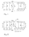
- Figure 1 shows an example of a three-phase frequency converter.
- the exemplary frequency converter may be composed of a rectifier 30 and an inverter 20, between which a DC intermediate circuit 10 is provided.
- the rectifier 30 and the inverter 20 may also be located physically separately, and one rectifier may supply a plurality of inverters via a common DC intermediate circuit 10.
- An example of the rectifier 30 is a diode bridge D1 to D6, which obtains its power supply via phase inputs U1, V1, W1 from an AC (Alternating Current) source, which is a 50 or 60-Hz three-phase AC network, for instance, and an example of the inverter 20 is a semiconductor bridge implemented by means of transistors S1 to S6, such as IGBTs (Insulated-gate Bipolar Transistor) or FETs (Field-Effect Transistor), or other controllable semiconductor switches, which are controlled according to a modulation or control scheme used.
- the inverter 20 may be used to control power transferred from the intermediate circuit 10 of the frequency converter to its output U2, V2, W2.
- the power supply from the output U2, V2, W2 of the inverter 20 may be a three-phase AC output, for example.
- the frequency converter may thus be used to control power transmitted from the AC supply to the electric motor driving the lift and, consequently, to control the movement of the lift.
- An object of the invention is to provide a method and an apparatus for implementing the method so as to solve or at least alleviate the above problem.
- the object of the invention is achieved by a method, a computer program product, and a motor drive that are characterized by what is stated in the independent claims. Preferred embodiments of the invention are described in the dependent claims.
- the invention is based on the idea of supplying power to a resistance with the frequency converter and monitoring a voltage of the DC intermediate circuit of the frequency converter during the supplying of power to the resistance with the frequency converter, whereby a disconnection of an AC phase input of the frequency converter from the AC supply can be detected on the basis of a fluctuation of the monitored voltage of the DC intermediate circuit of the frequency converter.
- the solution of the invention provides the advantage that a disconnection of an AC phase input of the frequency converter from the AC supply can be detected with a simple arrangement and potentially even before the load is driven by the motor drive. Also, if an existing resistance, such as a brake resistance, is used, then no additional components are necessarily needed in order to implement the invention.
- the application of the invention is not restricted to any specific system, but it may be applied to various motor drives comprising a frequency converter.
- a load driven by the motor drive may comprise a lift, a hoist or a crane, for example.
- the invention may be utilized in connection with any kind of load or loads.
- the use of the invention is not restricted to any system utilizing a specific basic frequency or to any specific voltage level.
- the invention may be applied to two-level or three-level converters, for example.
- FIG. 2 shows a circuit diagram of a main circuit of a frequency converter 100 according to an exemplary embodiment. It should be noted that the figure merely illustrates components necessary for understanding the invention. The number of various components may vary from that shown in the figure.
- the exemplary frequency converter 100 is a three-phase frequency converter and is composed of a rectifier 30 and an inverter 20, between which a DC intermediate circuit 10 is provided.
- the DC intermediate circuit 10 has a positive direct-current pole UDC+ and a negative direct-current pole UDC-.
- the voltage U DC of the DC intermediate circuit refers to a voltage between these two poles UDC+, UDC-.
- the rectifier 30 and the inverter 20 could be located physically separately, and one rectifier may supply a plurality of inverters via a common DC intermediate circuit 10.
- An example of the rectifier 30 is a diode bridge which comprises six diodes D1, D2, D3, D4, D5, D6, and which obtains its supply via phase inputs U1, V1, W1 from an AC source, which is a 50 or 60-Hz AC network, for instance.
- An example of the inverter 20 is a semiconductor bridge implemented by means of six controllable semiconductor switches S1, S2, S3, S4, S5, S6. Each of the six controllable semiconductor switches S1, S2, S3, S4, S5, S6 may have an antiparallel diode connected across the switch as illustrated.
- the controllable semiconductor switches S1 to S6 may be transistors, such as IGBTs (Insulated-gate Bipolar Transistor) or FETs (Field-Effect Transistor), or other controllable semiconductor switches.
- IGBTs Insulated-gate Bipolar Transistor
- FETs Field-Effect Transistor
- Figure 1 further shows a control arrangement 50 which can control the controllable semiconductor switches S1 to S6, for example, and more generally the operation of the frequency converter 100, for example.
- the control connections between the control arrangement 40 and the controllable elements, such as the semiconductor switches S1 to S6, are not shown for the sake of clarity.
- the control arrangement 40 may perform measurements of or receive input signals regarding various quantities, such as the voltage U DC of the DC intermediate circuit 10, in order to perform the control of the frequency converter. Possible measuring arrangements for such quantities are not shown in the figure for the sake of clarity.
- Figure 1 further shows an example of the DC intermediate circuit 10 of the exemplary converter, which DC intermediate circuit 10 comprises a capacitance C, or generally an energy storage, connected between the positive direct-current pole UDC+ and the negative direct-current pole UDC-.
- the capacitance C of the intermediate circuit 10 may comprise one or more capacitors.
- the structure of the intermediate circuit 10 could also be different, depending on the circuit configuration used.
- the exemplary converter of Figure 2 further comprises a brake chopper 40.
- brake choppers can be used in converters, such as frequency converters, for dissipating regenerated energy that cannot be fed back to the supplying network.
- converters such as frequency converters
- the motor acts as a generator and feeds power back to the supply.
- the rectifying bridge 30 of the frequency converter is not configured to feed the regenerated energy back to the supplying network, the voltage of the DC intermediate circuit 10 starts to increase.
- the voltage of the DC intermediate circuit 10 has increased to a certain limit, e.g.
- the brake chopper 40 may be activated and used to convert the electrical energy into heat in a brake resistance R in order to reduce the voltage of the DC intermediate circuit 10.
- Figure 2 shows an example of a main structure of the brake chopper 40 which comprises a controllable power semiconductor switch S7 connected in series with the brake resistance R between the two poles UDC+, UDC- of the DC intermediate circuit 10.
- the controllable semiconductor switch S7 and the brake resistance R may have an antiparallel diode connected across them as illustrated in the figure.
- the brake resistance R connected to the brake chopper 40 may be an external component and thus not necessarily part of the frequency converter or it can be integrated into the frequency converter.
- the controllable semiconductor switch S7 can be used to control a current flowing between the poles Udc+, Udc- and through the brake resistance R.
- the operation of the brake chopper 40 i.e. the controllable semiconductor switch S7 thereof, may be controlled with the control arrangement 50, for example.
- the control connections between the control arrangement 50 and the controllable semiconductor switch S7 of the brake chopper 40 are not shown for the sake of clarity.
- FIG 3 shows an example of a motor drive according to an embodiment.
- the exemplary motor drive comprises at least one electric motor 200, such as an asynchronous motor or a synchronous motor, or generally an AC motor, configured to drive a load 300, and a three-phase frequency converter 100, such as that described in connection with the example of Figure 2 , configured to receive supply from an AC supply 400 and to provide supply to the at least one electric motor 200.
- the AC supply 400 may be a three-phase AC network, for example.
- the motor drive comprises a resistance R, comprising one or more resistors, for example.
- the resistance R may be part of the frequency converter 100 or a separate element.
- the load 300 driven by the motor drive comprises a lift, such as a passenger lift or a goods lift.
- the load 300 driven by the motor drive may comprise a hoist or a crane or another kind of load.
- the capacitance C of the DC intermediate circuit 10 of the frequency converter 100 is charged to a peak value of line-to-line voltage U LL of the AC supply network 400 (for example, approximately 565 V in case of 400 V mains).
- U LL line-to-line voltage
- the DC intermediate circuit voltage U DC is approximately 540 V, which is the average of the six pulse voltage rectified by the three-phase diode bridge 30. If one of the phase inputs U1, V1, W1 of the frequency converter 100 is disconnected from the AC supply 400, the diode bridge 30 rectifies the line-to-line voltage between the remaining two phases. The peak value is still 2 U LL .
- the DC intermediate circuit voltage U DC does not change compared to the normal operation, if the inverter 100 is not loaded.
- the voltage formed by the rectifier 30 contains two pulses and the input voltage of the rectifier 30 is zero when the line-to-line voltage is zero.
- the voltage over the capacitance C of the DC intermediate circuit 10 contains a ripple with frequency 2*(supply network 400 frequency), when the inverter 20 is loaded.
- Figure 4 shows the voltages U a , U b of two healthy phase inputs U1, V1, W1 of the frequency converter 100 and the resulting voltage U DC of the DC intermediate circuit 10, when the inverter 20 is loaded.
- the frequency of the AC supply network 400 in the example of Figure 4 is 50 Hz and thus the period of the AC supply network 400 is 20 ms and, consequently, the period of the ripple in the voltage U DC of the DC intermediate circuit 10 is 10 ms as illustrated.
- a missing input phase i.e. a disconnection of one of the phase inputs U 1, V1, W1 of the frequency converter 100 from the AC supply 400
- U DC the voltage of the DC intermediate circuit 10.
- a difference between the maximum and minimum value of U DC during one period for example, 1/50 Hz or 1/60 Hz depending on the frequency of the AC supply network
- D DC the value of D DC
- a disconnection of an AC phase input U1, V1, W1 of the three-phase frequency converter 100 of the lift drive from the AC supply 400 can be performed by a) supplying power to the resistance R from the DC intermediate circuit 10 of the frequency converter 100, b) monitoring the voltage U DC of the DC intermediate circuit 40 of the frequency converter 100 during the supplying of power to the resistance R from the DC intermediate circuit 10 of the frequency converter 100, and c) detecting a disconnection of an AC phase input (U1, V1, W1) of the frequency converter (100) from the AC supply (400) on the basis of a fluctuation of the voltage of the DC intermediate circuit (10) of the frequency converter.
- power can be supplied from the DC intermediate circuit 10 of the frequency converter 100 to the brake resistance R by suitably controlling the controllable switch S7 of the brake chopper 40.
- the suitable amount of power supplied to the resistance R depends on the system characteristics. Thus, no specific values are given here. Generally, however, the amount of power supplied to the resistance R should be high enough such that the resulting ripple in the voltage U DC of the DC intermediate circuit 40 is detectable.
- c) comprises detecting a disconnection of an AC phase input U1, V1, W1 of the frequency converter from the AC supply 400 in response to a difference between a maximum value of the monitored voltage of the DC intermediate circuit of the frequency converter and a minimum value of the monitored voltage of the DC intermediate circuit of the frequency converter, or a quantity indicative thereof, exceeding a predetermined threshold.
- the actual detection of the disconnection of an AC phase input U1, V1, W1 of the frequency converter from the AC supply 400 may be based on directly calculating a difference max(U DC )-min(U DC ) based on the monitored voltage U DC and determining whether such calculated difference (possibly filtered) exceeds the predetermined threshold.
- the value of the predetermined threshold may depend on the system characteristics.
- the value of the predetermined threshold may also depend on the amount of power supplied to the resistance R.
- the value of the threshold may be set to a value which allows a fluctuation of approximately 13% (peak-to-peak) in the voltage of the DC intermediate circuit 10, or more generally to a value in the range of approximately 8% to 16%, for example.
- the predetermined threshold may also be adjustable by a user of the motor drive.
- c) comprises extracting a ripple component having a frequency of 2*(a frequency of the AC supply) from the monitored voltage of the DC intermediate circuit of the frequency converter, and detecting a disconnection of an AC phase input U1, V1, W1 of the frequency converter 100 from the AC supply 400 in response to an amplitude of the extracted ripple component, or a quantity indicative thereof, exceeding a predetermined threshold.
- the actual detection of the disconnection of an AC phase input U1, V1, W1 of the frequency converter from the AC supply 400 may be based on using frequency domain methods.
- the ripple component having a frequency of 2*(a frequency of the AC supply) in the voltage U DC of the DC intermediate circuit 40 may be extracted by using a band-pass filter, for example, or moving average filtering. It is then possible to determine whether the amplitude of the extracted ripple component, or a quantity indicative thereof, exceeds the predetermined threshold.
- the value of the predetermined threshold may depend on the system characteristics, for example, and may also be adjustable by a user of the motor drive.
- items a) to c) above may be performed in response to the motor drive receiving a command to drive the load 300.
- a command may refer to a command from a user, either inside the lift 300 or outside the lift, to the lift to move to a certain location, such as a certain floor, for example.
- Such a command may also refer to a command from a controlling system, such as the control arrangement 50, to the lift to move to a certain location without any user action involved.
- items a) to c) above may be performed before the load is driven. This is advantageous because this way the stopping of the load 300 abruptly, for example, can be avoided.
- items a) and b) above are performed for a duration of at least one period of the AC supply 400.
- one period corresponds to a time period of 1/50 Hz, i.e. 20 ms, for example.
- the maximum value and the minimum value or the ripple component having the frequency of 2*(a frequency of the AC supply) of the monitored voltage of the DC intermediate circuit during at least one period of the AC supply 400 may be considered in the detection, for example. In some cases it may be advantageous to apply a longer time period in order to make the detection more reliable.
- items a) and b) are performed for a duration of at least two periods of the AC supply.
- items a) and b) above may be performed first for a predetermined time period, such as at least one period of the AC supply 400, and only after that item c) is performed based on the observed voltage of the DC intermediate circuit 10 of the frequency converter during the predetermined time period.
- item c) simultaneously with items a) and b) such that the difference max(U DC )-min(U DC ), or a quantity indicative thereof, is continuously determined by continuously updating the values max(U DC ) and min(U DC ), or the ripple component having the frequency of 2*(a frequency of the AC supply) is continuously extracted, and compared with the predetermined threshold, for example.
- an alarm signal may be sent to an operator or a controller of the motor drive and/or the movement of the load 300 may be prevented by stopping the frequency converter 100, for example.
- control of the components of the motor drive can be performed by or via the control arrangement 40, which can also perform e.g. the normal modulation control of the frequency converter 100. It is also possible to use additional or separate logical or physical units (not shown) for performing the control functionality of the invention.
- the functionality of the invention could, for example, be implemented using a separate logic arrangement, which could be independent of the normal modulation control of the frequency converter 100, for example.
- the control arrangement 40 may measure, or receive measuring information of, the voltage of the DC intermediate circuit 10 needed in the various embodiments.
- the control arrangement 40 and/or a separate logic arrangement performing according to any one of the embodiments, or a combination thereof, can be implemented as one unit or as two or more separate units that are configured to implement the functionality of the various embodiments.
- the term 'unit' refers generally to a physical or logical entity, such as a physical device or a part thereof or a software routine.
- the control arrangement 40 according to any one of the embodiments may be implemented at least partly by means of one or more computers or corresponding digital signal processing (DSP) equipment provided with suitable software, for example.
- DSP digital signal processing
- Such a computer or digital signal processing equipment preferably comprises at least a working memory (RAM) providing a storage area for arithmetical operations, and a central processing unit (CPU), such as a general-purpose digital signal processor.
- RAM working memory
- CPU central processing unit
- the CPU may comprise a set of registers, an arithmetic logic unit, and a CPU control unit.
- the CPU control unit is controlled by a sequence of program instructions transferred to the CPU from the RAM.
- the CPU control unit may contain a number of microinstructions for basic operations. The implementation of microinstructions may vary depending on the CPU design.
- the program instructions may be coded by a programming language, which may be a high-level programming language, such as C, Java, etc., or a low-level programming language, such as a machine language, or an assembler.
- the computer may also have an operating system which may provide system services to a computer program written with the program instructions.
- the computer or other apparatus implementing the invention, or a part thereof, may further comprise suitable input means for receiving e.g.
- control arrangement 40 may be implemented at least partly by means of such analog circuits or programmable logic devices.
- the invention can be implemented in existing system elements or by using separate dedicated elements or devices in a centralized or distributed manner.
- Present frequency converter devices can comprise programmable logic devices, or processors and memory that can be utilized in the functions according to embodiments of the invention.
- all modifications and configurations required for implementing an embodiment e.g. in existing frequency converters may be performed as software routines, which may be implemented as added or updated software routines.
- software can be provided as a computer program product comprising computer program code which, when run on a computer, causes the computer or a corresponding arrangement to perform the functionality according to the invention as described above.
- Such a computer program code may be stored or generally embodied on a computer readable medium, such as a suitable memory, e.g. a flash memory or an optical memory, from which it is loadable to the unit or units executing the program code.
- a computer program code implementing the invention may be loaded to the unit or units executing the computer program code via a suitable data network, for example, and it may replace or update a possibly existing program code.
Landscapes
- Physics & Mathematics (AREA)
- General Physics & Mathematics (AREA)
- Engineering & Computer Science (AREA)
- Power Engineering (AREA)
- Inverter Devices (AREA)
Priority Applications (1)
| Application Number | Priority Date | Filing Date | Title |
|---|---|---|---|
| EP15157158.5A EP3065291A1 (de) | 2015-03-02 | 2015-03-02 | Verfahren zur Erkennung der Verbindungsunterbrechungen des Wechselstromphaseneingangs eines Motorantriebsfrequenzumrichters und Motorantrieb |
Applications Claiming Priority (1)
| Application Number | Priority Date | Filing Date | Title |
|---|---|---|---|
| EP15157158.5A EP3065291A1 (de) | 2015-03-02 | 2015-03-02 | Verfahren zur Erkennung der Verbindungsunterbrechungen des Wechselstromphaseneingangs eines Motorantriebsfrequenzumrichters und Motorantrieb |
Publications (1)
| Publication Number | Publication Date |
|---|---|
| EP3065291A1 true EP3065291A1 (de) | 2016-09-07 |
Family
ID=52595184
Family Applications (1)
| Application Number | Title | Priority Date | Filing Date |
|---|---|---|---|
| EP15157158.5A Withdrawn EP3065291A1 (de) | 2015-03-02 | 2015-03-02 | Verfahren zur Erkennung der Verbindungsunterbrechungen des Wechselstromphaseneingangs eines Motorantriebsfrequenzumrichters und Motorantrieb |
Country Status (1)
| Country | Link |
|---|---|
| EP (1) | EP3065291A1 (de) |
Cited By (1)
| Publication number | Priority date | Publication date | Assignee | Title |
|---|---|---|---|---|
| EP3502722A1 (de) * | 2017-12-22 | 2019-06-26 | KONE Corporation | Verfahren zur wartung eines frequenzumrichters und softwareprogramm, das diese realisiert |
Citations (2)
| Publication number | Priority date | Publication date | Assignee | Title |
|---|---|---|---|---|
| WO2009016267A1 (en) * | 2007-08-02 | 2009-02-05 | Kone Corporation | Control arrangement of an electric motor |
| US20140136130A1 (en) * | 2012-11-15 | 2014-05-15 | Rockwell Automation Technologies, Inc. | Method and Apparatus for Motor Drive Diagnostics |
-
2015
- 2015-03-02 EP EP15157158.5A patent/EP3065291A1/de not_active Withdrawn
Patent Citations (2)
| Publication number | Priority date | Publication date | Assignee | Title |
|---|---|---|---|---|
| WO2009016267A1 (en) * | 2007-08-02 | 2009-02-05 | Kone Corporation | Control arrangement of an electric motor |
| US20140136130A1 (en) * | 2012-11-15 | 2014-05-15 | Rockwell Automation Technologies, Inc. | Method and Apparatus for Motor Drive Diagnostics |
Cited By (3)
| Publication number | Priority date | Publication date | Assignee | Title |
|---|---|---|---|---|
| EP3502722A1 (de) * | 2017-12-22 | 2019-06-26 | KONE Corporation | Verfahren zur wartung eines frequenzumrichters und softwareprogramm, das diese realisiert |
| CN109959878A (zh) * | 2017-12-22 | 2019-07-02 | 通力股份公司 | 变频器的维护方法和实现其的软件程序 |
| US10598738B2 (en) | 2017-12-22 | 2020-03-24 | Kone Corporation | Method for maintenance of a frequency converter and software program realizing the same |
Similar Documents
| Publication | Publication Date | Title |
|---|---|---|
| JP5931148B2 (ja) | 静電容量計算部を有するpwm整流器 | |
| US9515484B2 (en) | System and method for reducing reactive current on a common DC bus with multiple inverters | |
| US10804891B2 (en) | Driving device | |
| CN104170234B (zh) | 功率转换系统及其电压检测装置 | |
| CN108988735B (zh) | 电动机驱动装置 | |
| JP6916305B2 (ja) | 電圧不平衡判定方法、および電力変換装置 | |
| JP6629893B2 (ja) | 浮遊容量を推定するモータ駆動装置 | |
| JPWO2016084213A1 (ja) | 監視装置と監視方法およびそれらを備える制御装置と制御方法 | |
| EP3435534B1 (de) | Stromwandlervorrichtung und verfahren zur steuerung davon | |
| EP3208551A1 (de) | Klimaanlage | |
| TWI577514B (zh) | Robot control system | |
| EP3232217B1 (de) | Bestimmung von filterkapazitäten | |
| CN108347213B (zh) | 电动机驱动装置 | |
| US9825577B2 (en) | Drive control device of a brushless DC motor | |
| KR101292683B1 (ko) | 제어 장치 및 제어 방법 | |
| EP3065291A1 (de) | Verfahren zur Erkennung der Verbindungsunterbrechungen des Wechselstromphaseneingangs eines Motorantriebsfrequenzumrichters und Motorantrieb | |
| US9148042B2 (en) | Method and apparatus for detection of drive misconfiguration in a multi-axis configuration | |
| US12146915B2 (en) | Deterioration estimation device and deterioration estimation program for power conversion device | |
| EP3242391B1 (de) | Verfahren zur überwachung von kapazitätsveränderungen in einem elektrischen system sowie elektrisches system | |
| EP3133732A1 (de) | Stromwandlervorrichtung und stromumwandlungsverfahren | |
| EP3229367B1 (de) | Stromwandler und regelungsverfahren für einen stromwandler | |
| JP5660222B2 (ja) | エレベーターの制御装置 | |
| US10236813B2 (en) | Method and device for detecting a control method of an inverter | |
| EP2894057A1 (de) | Verfahren zur Entladung des Gleichstrom-Zwischenschaltkreises eines Umwandlers sowie Umwandler | |
| TWI899320B (zh) | 馬達驅動裝置 |
Legal Events
| Date | Code | Title | Description |
|---|---|---|---|
| PUAI | Public reference made under article 153(3) epc to a published international application that has entered the european phase |
Free format text: ORIGINAL CODE: 0009012 |
|
| AK | Designated contracting states |
Kind code of ref document: A1 Designated state(s): AL AT BE BG CH CY CZ DE DK EE ES FI FR GB GR HR HU IE IS IT LI LT LU LV MC MK MT NL NO PL PT RO RS SE SI SK SM TR |
|
| AX | Request for extension of the european patent |
Extension state: BA ME |
|
| STAA | Information on the status of an ep patent application or granted ep patent |
Free format text: STATUS: THE APPLICATION IS DEEMED TO BE WITHDRAWN |
|
| 18D | Application deemed to be withdrawn |
Effective date: 20170308 |