EP3065151A1 - Communication module - Google Patents
Communication module Download PDFInfo
- Publication number
- EP3065151A1 EP3065151A1 EP14859136.5A EP14859136A EP3065151A1 EP 3065151 A1 EP3065151 A1 EP 3065151A1 EP 14859136 A EP14859136 A EP 14859136A EP 3065151 A1 EP3065151 A1 EP 3065151A1
- Authority
- EP
- European Patent Office
- Prior art keywords
- resin
- sheet member
- communication module
- mass
- heat
- Prior art date
- Legal status (The legal status is an assumption and is not a legal conclusion. Google has not performed a legal analysis and makes no representation as to the accuracy of the status listed.)
- Pending
Links
- 238000004891 communication Methods 0.000 title claims abstract description 63
- 229920005989 resin Polymers 0.000 claims description 54
- 239000011347 resin Substances 0.000 claims description 54
- 239000003822 epoxy resin Substances 0.000 claims description 36
- 229920000647 polyepoxide Polymers 0.000 claims description 36
- 239000002245 particle Substances 0.000 claims description 26
- 239000011342 resin composition Substances 0.000 claims description 21
- 239000005011 phenolic resin Substances 0.000 claims description 18
- 229920000178 Acrylic resin Polymers 0.000 claims description 14
- 239000004925 Acrylic resin Substances 0.000 claims description 14
- 229910052582 BN Inorganic materials 0.000 claims description 7
- PZNSFCLAULLKQX-UHFFFAOYSA-N Boron nitride Chemical compound N#B PZNSFCLAULLKQX-UHFFFAOYSA-N 0.000 claims description 7
- 238000009413 insulation Methods 0.000 claims description 7
- 238000010292 electrical insulation Methods 0.000 abstract description 2
- 230000005611 electricity Effects 0.000 abstract 1
- -1 for example Polymers 0.000 description 33
- 239000012790 adhesive layer Substances 0.000 description 17
- 239000010410 layer Substances 0.000 description 17
- 239000000758 substrate Substances 0.000 description 17
- 229920001187 thermosetting polymer Polymers 0.000 description 17
- OKTJSMMVPCPJKN-UHFFFAOYSA-N Carbon Chemical compound [C] OKTJSMMVPCPJKN-UHFFFAOYSA-N 0.000 description 16
- 230000000052 comparative effect Effects 0.000 description 16
- 229910002804 graphite Inorganic materials 0.000 description 15
- 239000010439 graphite Substances 0.000 description 15
- 239000000178 monomer Substances 0.000 description 15
- 230000005540 biological transmission Effects 0.000 description 13
- 239000000853 adhesive Substances 0.000 description 10
- 230000001070 adhesive effect Effects 0.000 description 10
- ZWEHNKRNPOVVGH-UHFFFAOYSA-N 2-Butanone Chemical compound CCC(C)=O ZWEHNKRNPOVVGH-UHFFFAOYSA-N 0.000 description 9
- 239000003054 catalyst Substances 0.000 description 9
- 238000011156 evaluation Methods 0.000 description 9
- 125000002887 hydroxy group Chemical group [H]O* 0.000 description 9
- 229920003986 novolac Polymers 0.000 description 9
- NIXOWILDQLNWCW-UHFFFAOYSA-M Acrylate Chemical compound [O-]C(=O)C=C NIXOWILDQLNWCW-UHFFFAOYSA-M 0.000 description 8
- 239000004841 bisphenol A epoxy resin Substances 0.000 description 8
- 239000004593 Epoxy Substances 0.000 description 7
- 238000000034 method Methods 0.000 description 7
- 229920000139 polyethylene terephthalate Polymers 0.000 description 7
- 239000005020 polyethylene terephthalate Substances 0.000 description 7
- RAXXELZNTBOGNW-UHFFFAOYSA-N imidazole Natural products C1=CNC=N1 RAXXELZNTBOGNW-UHFFFAOYSA-N 0.000 description 6
- 229910052751 metal Inorganic materials 0.000 description 6
- 239000002184 metal Substances 0.000 description 6
- 239000002904 solvent Substances 0.000 description 6
- 238000001035 drying Methods 0.000 description 5
- 238000002156 mixing Methods 0.000 description 5
- 230000009467 reduction Effects 0.000 description 5
- 239000000126 substance Substances 0.000 description 5
- 229920005992 thermoplastic resin Polymers 0.000 description 5
- RYGMFSIKBFXOCR-UHFFFAOYSA-N Copper Chemical compound [Cu] RYGMFSIKBFXOCR-UHFFFAOYSA-N 0.000 description 4
- ISWSIDIOOBJBQZ-UHFFFAOYSA-N Phenol Chemical compound OC1=CC=CC=C1 ISWSIDIOOBJBQZ-UHFFFAOYSA-N 0.000 description 4
- 125000000217 alkyl group Chemical group 0.000 description 4
- 229910052782 aluminium Inorganic materials 0.000 description 4
- XAGFODPZIPBFFR-UHFFFAOYSA-N aluminium Chemical compound [Al] XAGFODPZIPBFFR-UHFFFAOYSA-N 0.000 description 4
- IISBACLAFKSPIT-UHFFFAOYSA-N bisphenol A Chemical compound C=1C=C(O)C=CC=1C(C)(C)C1=CC=C(O)C=C1 IISBACLAFKSPIT-UHFFFAOYSA-N 0.000 description 4
- 239000003795 chemical substances by application Substances 0.000 description 4
- 239000004020 conductor Substances 0.000 description 4
- LNEPOXFFQSENCJ-UHFFFAOYSA-N haloperidol Chemical compound C1CC(O)(C=2C=CC(Cl)=CC=2)CCN1CCCC(=O)C1=CC=C(F)C=C1 LNEPOXFFQSENCJ-UHFFFAOYSA-N 0.000 description 4
- 238000010438 heat treatment Methods 0.000 description 4
- 238000005259 measurement Methods 0.000 description 4
- 229920001721 polyimide Polymers 0.000 description 4
- 238000003825 pressing Methods 0.000 description 4
- XEKOWRVHYACXOJ-UHFFFAOYSA-N Ethyl acetate Chemical compound CCOC(C)=O XEKOWRVHYACXOJ-UHFFFAOYSA-N 0.000 description 3
- YCKRFDGAMUMZLT-UHFFFAOYSA-N Fluorine atom Chemical compound [F] YCKRFDGAMUMZLT-UHFFFAOYSA-N 0.000 description 3
- OKKJLVBELUTLKV-UHFFFAOYSA-N Methanol Chemical compound OC OKKJLVBELUTLKV-UHFFFAOYSA-N 0.000 description 3
- ZMXDDKWLCZADIW-UHFFFAOYSA-N N,N-Dimethylformamide Chemical compound CN(C)C=O ZMXDDKWLCZADIW-UHFFFAOYSA-N 0.000 description 3
- BQCADISMDOOEFD-UHFFFAOYSA-N Silver Chemical compound [Ag] BQCADISMDOOEFD-UHFFFAOYSA-N 0.000 description 3
- PPBRXRYQALVLMV-UHFFFAOYSA-N Styrene Chemical compound C=CC1=CC=CC=C1 PPBRXRYQALVLMV-UHFFFAOYSA-N 0.000 description 3
- UUQQGGWZVKUCBD-UHFFFAOYSA-N [4-(hydroxymethyl)-2-phenyl-1h-imidazol-5-yl]methanol Chemical compound N1C(CO)=C(CO)N=C1C1=CC=CC=C1 UUQQGGWZVKUCBD-UHFFFAOYSA-N 0.000 description 3
- 239000000654 additive Substances 0.000 description 3
- 125000005907 alkyl ester group Chemical group 0.000 description 3
- 125000003178 carboxy group Chemical group [H]OC(*)=O 0.000 description 3
- 229910052802 copper Inorganic materials 0.000 description 3
- 239000010949 copper Substances 0.000 description 3
- 230000000694 effects Effects 0.000 description 3
- 230000005674 electromagnetic induction Effects 0.000 description 3
- 239000011737 fluorine Substances 0.000 description 3
- 229910052731 fluorine Inorganic materials 0.000 description 3
- 125000003055 glycidyl group Chemical group C(C1CO1)* 0.000 description 3
- PCHJSUWPFVWCPO-UHFFFAOYSA-N gold Chemical compound [Au] PCHJSUWPFVWCPO-UHFFFAOYSA-N 0.000 description 3
- ZFSLODLOARCGLH-UHFFFAOYSA-N isocyanuric acid Chemical compound OC1=NC(O)=NC(O)=N1 ZFSLODLOARCGLH-UHFFFAOYSA-N 0.000 description 3
- 229920003145 methacrylic acid copolymer Polymers 0.000 description 3
- 230000002093 peripheral effect Effects 0.000 description 3
- 229920000642 polymer Polymers 0.000 description 3
- 239000007787 solid Substances 0.000 description 3
- NIXOWILDQLNWCW-UHFFFAOYSA-N 2-Propenoic acid Natural products OC(=O)C=C NIXOWILDQLNWCW-UHFFFAOYSA-N 0.000 description 2
- LXBGSDVWAMZHDD-UHFFFAOYSA-N 2-methyl-1h-imidazole Chemical compound CC1=NC=CN1 LXBGSDVWAMZHDD-UHFFFAOYSA-N 0.000 description 2
- CSCPPACGZOOCGX-UHFFFAOYSA-N Acetone Chemical compound CC(C)=O CSCPPACGZOOCGX-UHFFFAOYSA-N 0.000 description 2
- 229930185605 Bisphenol Natural products 0.000 description 2
- VTYYLEPIZMXCLO-UHFFFAOYSA-L Calcium carbonate Chemical compound [Ca+2].[O-]C([O-])=O VTYYLEPIZMXCLO-UHFFFAOYSA-L 0.000 description 2
- LFQSCWFLJHTTHZ-UHFFFAOYSA-N Ethanol Chemical compound CCO LFQSCWFLJHTTHZ-UHFFFAOYSA-N 0.000 description 2
- VZCYOOQTPOCHFL-OWOJBTEDSA-N Fumaric acid Chemical compound OC(=O)\C=C\C(O)=O VZCYOOQTPOCHFL-OWOJBTEDSA-N 0.000 description 2
- XEEYBQQBJWHFJM-UHFFFAOYSA-N Iron Chemical compound [Fe] XEEYBQQBJWHFJM-UHFFFAOYSA-N 0.000 description 2
- KFZMGEQAYNKOFK-UHFFFAOYSA-N Isopropanol Chemical compound CC(C)O KFZMGEQAYNKOFK-UHFFFAOYSA-N 0.000 description 2
- UFWIBTONFRDIAS-UHFFFAOYSA-N Naphthalene Chemical compound C1=CC=CC2=CC=CC=C21 UFWIBTONFRDIAS-UHFFFAOYSA-N 0.000 description 2
- 239000004677 Nylon Substances 0.000 description 2
- 239000004642 Polyimide Substances 0.000 description 2
- 229910052581 Si3N4 Inorganic materials 0.000 description 2
- VYPSYNLAJGMNEJ-UHFFFAOYSA-N Silicium dioxide Chemical compound O=[Si]=O VYPSYNLAJGMNEJ-UHFFFAOYSA-N 0.000 description 2
- XLOMVQKBTHCTTD-UHFFFAOYSA-N Zinc monoxide Chemical compound [Zn]=O XLOMVQKBTHCTTD-UHFFFAOYSA-N 0.000 description 2
- 239000003522 acrylic cement Substances 0.000 description 2
- XECAHXYUAAWDEL-UHFFFAOYSA-N acrylonitrile butadiene styrene Chemical compound C=CC=C.C=CC#N.C=CC1=CC=CC=C1 XECAHXYUAAWDEL-UHFFFAOYSA-N 0.000 description 2
- 229920000122 acrylonitrile butadiene styrene Polymers 0.000 description 2
- 239000004676 acrylonitrile butadiene styrene Substances 0.000 description 2
- 125000004432 carbon atom Chemical group C* 0.000 description 2
- 229920001577 copolymer Polymers 0.000 description 2
- PMHQVHHXPFUNSP-UHFFFAOYSA-M copper(1+);methylsulfanylmethane;bromide Chemical compound Br[Cu].CSC PMHQVHHXPFUNSP-UHFFFAOYSA-M 0.000 description 2
- ZUOUZKKEUPVFJK-UHFFFAOYSA-N diphenyl Chemical compound C1=CC=CC=C1C1=CC=CC=C1 ZUOUZKKEUPVFJK-UHFFFAOYSA-N 0.000 description 2
- 238000009826 distribution Methods 0.000 description 2
- 125000003438 dodecyl group Chemical group [H]C([H])([H])C([H])([H])C([H])([H])C([H])([H])C([H])([H])C([H])([H])C([H])([H])C([H])([H])C([H])([H])C([H])([H])C([H])([H])C([H])([H])* 0.000 description 2
- 238000005227 gel permeation chromatography Methods 0.000 description 2
- 229910052737 gold Inorganic materials 0.000 description 2
- 239000010931 gold Substances 0.000 description 2
- 239000000463 material Substances 0.000 description 2
- 229910044991 metal oxide Inorganic materials 0.000 description 2
- 150000004706 metal oxides Chemical class 0.000 description 2
- 229920001778 nylon Polymers 0.000 description 2
- QWVGKYWNOKOFNN-UHFFFAOYSA-N o-cresol Chemical compound CC1=CC=CC=C1O QWVGKYWNOKOFNN-UHFFFAOYSA-N 0.000 description 2
- 229920000058 polyacrylate Polymers 0.000 description 2
- 229920000515 polycarbonate Polymers 0.000 description 2
- 239000004417 polycarbonate Substances 0.000 description 2
- 239000009719 polyimide resin Substances 0.000 description 2
- 229920001296 polysiloxane Polymers 0.000 description 2
- 238000002360 preparation method Methods 0.000 description 2
- 235000012239 silicon dioxide Nutrition 0.000 description 2
- HQVNEWCFYHHQES-UHFFFAOYSA-N silicon nitride Chemical compound N12[Si]34N5[Si]62N3[Si]51N64 HQVNEWCFYHHQES-UHFFFAOYSA-N 0.000 description 2
- 229910052709 silver Inorganic materials 0.000 description 2
- 239000004332 silver Substances 0.000 description 2
- 125000004079 stearyl group Chemical group [H]C([*])([H])C([H])([H])C([H])([H])C([H])([H])C([H])([H])C([H])([H])C([H])([H])C([H])([H])C([H])([H])C([H])([H])C([H])([H])C([H])([H])C([H])([H])C([H])([H])C([H])([H])C([H])([H])C([H])([H])C([H])([H])[H] 0.000 description 2
- 230000001629 suppression Effects 0.000 description 2
- VZCYOOQTPOCHFL-UHFFFAOYSA-N trans-butenedioic acid Natural products OC(=O)C=CC(O)=O VZCYOOQTPOCHFL-UHFFFAOYSA-N 0.000 description 2
- XLYOFNOQVPJJNP-UHFFFAOYSA-N water Substances O XLYOFNOQVPJJNP-UHFFFAOYSA-N 0.000 description 2
- ARXJGSRGQADJSQ-UHFFFAOYSA-N 1-methoxypropan-2-ol Chemical compound COCC(C)O ARXJGSRGQADJSQ-UHFFFAOYSA-N 0.000 description 1
- SMZOUWXMTYCWNB-UHFFFAOYSA-N 2-(2-methoxy-5-methylphenyl)ethanamine Chemical compound COC1=CC=C(C)C=C1CCN SMZOUWXMTYCWNB-UHFFFAOYSA-N 0.000 description 1
- JAHNSTQSQJOJLO-UHFFFAOYSA-N 2-(3-fluorophenyl)-1h-imidazole Chemical compound FC1=CC=CC(C=2NC=CN=2)=C1 JAHNSTQSQJOJLO-UHFFFAOYSA-N 0.000 description 1
- KUBDPQJOLOUJRM-UHFFFAOYSA-N 2-(chloromethyl)oxirane;4-[2-(4-hydroxyphenyl)propan-2-yl]phenol Chemical compound ClCC1CO1.C=1C=C(O)C=CC=1C(C)(C)C1=CC=C(O)C=C1 KUBDPQJOLOUJRM-UHFFFAOYSA-N 0.000 description 1
- QCBSYPYHCJMQGB-UHFFFAOYSA-N 2-ethyl-1,3,5-triazine Chemical compound CCC1=NC=NC=N1 QCBSYPYHCJMQGB-UHFFFAOYSA-N 0.000 description 1
- 125000000954 2-hydroxyethyl group Chemical group [H]C([*])([H])C([H])([H])O[H] 0.000 description 1
- QTWJRLJHJPIABL-UHFFFAOYSA-N 2-methylphenol;3-methylphenol;4-methylphenol Chemical compound CC1=CC=C(O)C=C1.CC1=CC=CC(O)=C1.CC1=CC=CC=C1O QTWJRLJHJPIABL-UHFFFAOYSA-N 0.000 description 1
- AUZRCMMVHXRSGT-UHFFFAOYSA-N 2-methylpropane-1-sulfonic acid;prop-2-enamide Chemical compound NC(=O)C=C.CC(C)CS(O)(=O)=O AUZRCMMVHXRSGT-UHFFFAOYSA-N 0.000 description 1
- ZCUJYXPAKHMBAZ-UHFFFAOYSA-N 2-phenyl-1h-imidazole Chemical compound C1=CNC(C=2C=CC=CC=2)=N1 ZCUJYXPAKHMBAZ-UHFFFAOYSA-N 0.000 description 1
- AGBXYHCHUYARJY-UHFFFAOYSA-N 2-phenylethenesulfonic acid Chemical compound OS(=O)(=O)C=CC1=CC=CC=C1 AGBXYHCHUYARJY-UHFFFAOYSA-N 0.000 description 1
- YYIOIHBNJMVSBH-UHFFFAOYSA-N 2-prop-2-enoyloxynaphthalene-1-sulfonic acid Chemical compound C1=CC=C2C(S(=O)(=O)O)=C(OC(=O)C=C)C=CC2=C1 YYIOIHBNJMVSBH-UHFFFAOYSA-N 0.000 description 1
- WJQOZHYUIDYNHM-UHFFFAOYSA-N 2-tert-Butylphenol Chemical compound CC(C)(C)C1=CC=CC=C1O WJQOZHYUIDYNHM-UHFFFAOYSA-N 0.000 description 1
- LLEASVZEQBICSN-UHFFFAOYSA-N 2-undecyl-1h-imidazole Chemical compound CCCCCCCCCCCC1=NC=CN1 LLEASVZEQBICSN-UHFFFAOYSA-N 0.000 description 1
- DOTJTDPXTXRURS-UHFFFAOYSA-N 3-[4-(hydroxymethyl)cyclohexyl]-2-methylprop-2-enoic acid Chemical compound OC(=O)C(C)=CC1CCC(CO)CC1 DOTJTDPXTXRURS-UHFFFAOYSA-N 0.000 description 1
- OFNISBHGPNMTMS-UHFFFAOYSA-N 3-methylideneoxolane-2,5-dione Chemical compound C=C1CC(=O)OC1=O OFNISBHGPNMTMS-UHFFFAOYSA-N 0.000 description 1
- CYUZOYPRAQASLN-UHFFFAOYSA-N 3-prop-2-enoyloxypropanoic acid Chemical compound OC(=O)CCOC(=O)C=C CYUZOYPRAQASLN-UHFFFAOYSA-N 0.000 description 1
- VPWNQTHUCYMVMZ-UHFFFAOYSA-N 4,4'-sulfonyldiphenol Chemical compound C1=CC(O)=CC=C1S(=O)(=O)C1=CC=C(O)C=C1 VPWNQTHUCYMVMZ-UHFFFAOYSA-N 0.000 description 1
- SXIFAEWFOJETOA-UHFFFAOYSA-N 4-hydroxy-butyl Chemical group [CH2]CCCO SXIFAEWFOJETOA-UHFFFAOYSA-N 0.000 description 1
- ULKLGIFJWFIQFF-UHFFFAOYSA-N 5K8XI641G3 Chemical compound CCC1=NC=C(C)N1 ULKLGIFJWFIQFF-UHFFFAOYSA-N 0.000 description 1
- JSZCJJRQCFZXCI-UHFFFAOYSA-N 6-prop-2-enoyloxyhexanoic acid Chemical compound OC(=O)CCCCCOC(=O)C=C JSZCJJRQCFZXCI-UHFFFAOYSA-N 0.000 description 1
- NLHHRLWOUZZQLW-UHFFFAOYSA-N Acrylonitrile Chemical compound C=CC#N NLHHRLWOUZZQLW-UHFFFAOYSA-N 0.000 description 1
- 229920002799 BoPET Polymers 0.000 description 1
- JJLJMEJHUUYSSY-UHFFFAOYSA-L Copper hydroxide Chemical compound [OH-].[OH-].[Cu+2] JJLJMEJHUUYSSY-UHFFFAOYSA-L 0.000 description 1
- 239000005750 Copper hydroxide Substances 0.000 description 1
- QPLDLSVMHZLSFG-UHFFFAOYSA-N Copper oxide Chemical compound [Cu]=O QPLDLSVMHZLSFG-UHFFFAOYSA-N 0.000 description 1
- 239000005751 Copper oxide Substances 0.000 description 1
- 239000004641 Diallyl-phthalate Substances 0.000 description 1
- OTMSDBZUPAUEDD-UHFFFAOYSA-N Ethane Chemical compound CC OTMSDBZUPAUEDD-UHFFFAOYSA-N 0.000 description 1
- 229910002601 GaN Inorganic materials 0.000 description 1
- JMASRVWKEDWRBT-UHFFFAOYSA-N Gallium nitride Chemical compound [Ga]#N JMASRVWKEDWRBT-UHFFFAOYSA-N 0.000 description 1
- 244000043261 Hevea brasiliensis Species 0.000 description 1
- HBBGRARXTFLTSG-UHFFFAOYSA-N Lithium ion Chemical compound [Li+] HBBGRARXTFLTSG-UHFFFAOYSA-N 0.000 description 1
- 239000004640 Melamine resin Substances 0.000 description 1
- 229920000877 Melamine resin Polymers 0.000 description 1
- CERQOIWHTDAKMF-UHFFFAOYSA-N Methacrylic acid Chemical compound CC(=C)C(O)=O CERQOIWHTDAKMF-UHFFFAOYSA-N 0.000 description 1
- IGFHQQFPSIBGKE-UHFFFAOYSA-N Nonylphenol Natural products CCCCCCCCCC1=CC=C(O)C=C1 IGFHQQFPSIBGKE-UHFFFAOYSA-N 0.000 description 1
- NYXVMNRGBMOSIY-UHFFFAOYSA-N OCCC=CC(=O)OP(O)(O)=O Chemical compound OCCC=CC(=O)OP(O)(O)=O NYXVMNRGBMOSIY-UHFFFAOYSA-N 0.000 description 1
- NBIIXXVUZAFLBC-UHFFFAOYSA-N Phosphoric acid Chemical group OP(O)(O)=O NBIIXXVUZAFLBC-UHFFFAOYSA-N 0.000 description 1
- 239000004962 Polyamide-imide Substances 0.000 description 1
- 239000005062 Polybutadiene Substances 0.000 description 1
- 239000004698 Polyethylene Substances 0.000 description 1
- 239000004743 Polypropylene Substances 0.000 description 1
- 239000004793 Polystyrene Substances 0.000 description 1
- 239000004820 Pressure-sensitive adhesive Substances 0.000 description 1
- OFOBLEOULBTSOW-UHFFFAOYSA-N Propanedioic acid Natural products OC(=O)CC(O)=O OFOBLEOULBTSOW-UHFFFAOYSA-N 0.000 description 1
- GWEVSGVZZGPLCZ-UHFFFAOYSA-N Titan oxide Chemical compound O=[Ti]=O GWEVSGVZZGPLCZ-UHFFFAOYSA-N 0.000 description 1
- YXFVVABEGXRONW-UHFFFAOYSA-N Toluene Chemical compound CC1=CC=CC=C1 YXFVVABEGXRONW-UHFFFAOYSA-N 0.000 description 1
- 229920001807 Urea-formaldehyde Polymers 0.000 description 1
- 150000008065 acid anhydrides Chemical class 0.000 description 1
- 230000000996 additive effect Effects 0.000 description 1
- 150000001298 alcohols Chemical class 0.000 description 1
- 125000005250 alkyl acrylate group Chemical group 0.000 description 1
- WNROFYMDJYEPJX-UHFFFAOYSA-K aluminium hydroxide Chemical compound [OH-].[OH-].[OH-].[Al+3] WNROFYMDJYEPJX-UHFFFAOYSA-K 0.000 description 1
- PNEYBMLMFCGWSK-UHFFFAOYSA-N aluminium oxide Inorganic materials [O-2].[O-2].[O-2].[Al+3].[Al+3] PNEYBMLMFCGWSK-UHFFFAOYSA-N 0.000 description 1
- VCNTUJWBXWAWEJ-UHFFFAOYSA-J aluminum;sodium;dicarbonate Chemical compound [Na+].[Al+3].[O-]C([O-])=O.[O-]C([O-])=O VCNTUJWBXWAWEJ-UHFFFAOYSA-J 0.000 description 1
- 150000001408 amides Chemical class 0.000 description 1
- 125000003277 amino group Chemical group 0.000 description 1
- 229920003180 amino resin Polymers 0.000 description 1
- RQPZNWPYLFFXCP-UHFFFAOYSA-L barium dihydroxide Chemical compound [OH-].[OH-].[Ba+2] RQPZNWPYLFFXCP-UHFFFAOYSA-L 0.000 description 1
- 229910001863 barium hydroxide Inorganic materials 0.000 description 1
- JRPBQTZRNDNNOP-UHFFFAOYSA-N barium titanate Chemical compound [Ba+2].[Ba+2].[O-][Ti]([O-])([O-])[O-] JRPBQTZRNDNNOP-UHFFFAOYSA-N 0.000 description 1
- 229910002113 barium titanate Inorganic materials 0.000 description 1
- 239000004305 biphenyl Substances 0.000 description 1
- 235000010290 biphenyl Nutrition 0.000 description 1
- QUDWYFHPNIMBFC-UHFFFAOYSA-N bis(prop-2-enyl) benzene-1,2-dicarboxylate Chemical compound C=CCOC(=O)C1=CC=CC=C1C(=O)OCC=C QUDWYFHPNIMBFC-UHFFFAOYSA-N 0.000 description 1
- ZFVMWEVVKGLCIJ-UHFFFAOYSA-N bisphenol AF Chemical compound C1=CC(O)=CC=C1C(C(F)(F)F)(C(F)(F)F)C1=CC=C(O)C=C1 ZFVMWEVVKGLCIJ-UHFFFAOYSA-N 0.000 description 1
- 239000004842 bisphenol F epoxy resin Substances 0.000 description 1
- 229910001593 boehmite Inorganic materials 0.000 description 1
- 229910021538 borax Inorganic materials 0.000 description 1
- 229920005549 butyl rubber Polymers 0.000 description 1
- 229910000019 calcium carbonate Inorganic materials 0.000 description 1
- AXCZMVOFGPJBDE-UHFFFAOYSA-L calcium dihydroxide Chemical compound [OH-].[OH-].[Ca+2] AXCZMVOFGPJBDE-UHFFFAOYSA-L 0.000 description 1
- 239000000920 calcium hydroxide Substances 0.000 description 1
- 229910001861 calcium hydroxide Inorganic materials 0.000 description 1
- 229910052799 carbon Inorganic materials 0.000 description 1
- 230000015556 catabolic process Effects 0.000 description 1
- 239000000919 ceramic Substances 0.000 description 1
- 230000008859 change Effects 0.000 description 1
- 238000006243 chemical reaction Methods 0.000 description 1
- 150000001875 compounds Chemical class 0.000 description 1
- 239000011889 copper foil Substances 0.000 description 1
- 229910001956 copper hydroxide Inorganic materials 0.000 description 1
- 229910000431 copper oxide Inorganic materials 0.000 description 1
- 229930003836 cresol Natural products 0.000 description 1
- 239000003431 cross linking reagent Substances 0.000 description 1
- LDHQCZJRKDOVOX-NSCUHMNNSA-N crotonic acid Chemical compound C\C=C\C(O)=O LDHQCZJRKDOVOX-NSCUHMNNSA-N 0.000 description 1
- 230000001186 cumulative effect Effects 0.000 description 1
- 125000000113 cyclohexyl group Chemical group [H]C1([H])C([H])([H])C([H])([H])C([H])(*)C([H])([H])C1([H])[H] 0.000 description 1
- 229910001647 dawsonite Inorganic materials 0.000 description 1
- 125000002704 decyl group Chemical group [H]C([H])([H])C([H])([H])C([H])([H])C([H])([H])C([H])([H])C([H])([H])C([H])([H])C([H])([H])C([H])([H])C([H])([H])* 0.000 description 1
- 238000006731 degradation reaction Methods 0.000 description 1
- GDVKFRBCXAPAQJ-UHFFFAOYSA-A dialuminum;hexamagnesium;carbonate;hexadecahydroxide Chemical compound [OH-].[OH-].[OH-].[OH-].[OH-].[OH-].[OH-].[OH-].[OH-].[OH-].[OH-].[OH-].[OH-].[OH-].[OH-].[OH-].[Mg+2].[Mg+2].[Mg+2].[Mg+2].[Mg+2].[Mg+2].[Al+3].[Al+3].[O-]C([O-])=O GDVKFRBCXAPAQJ-UHFFFAOYSA-A 0.000 description 1
- 229910003460 diamond Inorganic materials 0.000 description 1
- 239000010432 diamond Substances 0.000 description 1
- ZIWYFFIJXBGVMZ-UHFFFAOYSA-N dioxotin hydrate Chemical compound O.O=[Sn]=O ZIWYFFIJXBGVMZ-UHFFFAOYSA-N 0.000 description 1
- NJLLQSBAHIKGKF-UHFFFAOYSA-N dipotassium dioxido(oxo)titanium Chemical compound [K+].[K+].[O-][Ti]([O-])=O NJLLQSBAHIKGKF-UHFFFAOYSA-N 0.000 description 1
- 229920006332 epoxy adhesive Polymers 0.000 description 1
- 125000003700 epoxy group Chemical group 0.000 description 1
- 150000002148 esters Chemical class 0.000 description 1
- 150000002170 ethers Chemical class 0.000 description 1
- 125000001495 ethyl group Chemical group [H]C([H])([H])C([H])([H])* 0.000 description 1
- XPNLOZNCOBKRNJ-UHFFFAOYSA-N ethyl prop-2-enoate;methyl 2-methylprop-2-enoate Chemical compound CCOC(=O)C=C.COC(=O)C(C)=C XPNLOZNCOBKRNJ-UHFFFAOYSA-N 0.000 description 1
- 239000005038 ethylene vinyl acetate Substances 0.000 description 1
- 239000011888 foil Substances 0.000 description 1
- 239000001530 fumaric acid Substances 0.000 description 1
- VOZRXNHHFUQHIL-UHFFFAOYSA-N glycidyl methacrylate Chemical compound CC(=C)C(=O)OCC1CO1 VOZRXNHHFUQHIL-UHFFFAOYSA-N 0.000 description 1
- 239000004845 glycidylamine epoxy resin Substances 0.000 description 1
- 230000020169 heat generation Effects 0.000 description 1
- 125000003187 heptyl group Chemical group [H]C([*])([H])C([H])([H])C([H])([H])C([H])([H])C([H])([H])C([H])([H])C([H])([H])[H] 0.000 description 1
- 125000004051 hexyl group Chemical group [H]C([H])([H])C([H])([H])C([H])([H])C([H])([H])C([H])([H])C([H])([H])* 0.000 description 1
- WJRBRSLFGCUECM-UHFFFAOYSA-N hydantoin Chemical compound O=C1CNC(=O)N1 WJRBRSLFGCUECM-UHFFFAOYSA-N 0.000 description 1
- 229940091173 hydantoin Drugs 0.000 description 1
- 229910001701 hydrotalcite Inorganic materials 0.000 description 1
- 229960001545 hydrotalcite Drugs 0.000 description 1
- 150000004679 hydroxides Chemical class 0.000 description 1
- FAHBNUUHRFUEAI-UHFFFAOYSA-M hydroxidooxidoaluminium Chemical compound O[Al]=O FAHBNUUHRFUEAI-UHFFFAOYSA-M 0.000 description 1
- 239000011256 inorganic filler Substances 0.000 description 1
- 229910003475 inorganic filler Inorganic materials 0.000 description 1
- 229910052742 iron Inorganic materials 0.000 description 1
- 235000014413 iron hydroxide Nutrition 0.000 description 1
- NCNCGGDMXMBVIA-UHFFFAOYSA-L iron(ii) hydroxide Chemical compound [OH-].[OH-].[Fe+2] NCNCGGDMXMBVIA-UHFFFAOYSA-L 0.000 description 1
- 125000000959 isobutyl group Chemical group [H]C([H])([H])C([H])(C([H])([H])[H])C([H])([H])* 0.000 description 1
- 125000001972 isopentyl group Chemical group [H]C([H])([H])C([H])(C([H])([H])[H])C([H])([H])C([H])([H])* 0.000 description 1
- 229920003049 isoprene rubber Polymers 0.000 description 1
- 125000001449 isopropyl group Chemical group [H]C([H])([H])C([H])(*)C([H])([H])[H] 0.000 description 1
- 150000002576 ketones Chemical class 0.000 description 1
- 239000004973 liquid crystal related substance Substances 0.000 description 1
- 229910001416 lithium ion Inorganic materials 0.000 description 1
- ZLNQQNXFFQJAID-UHFFFAOYSA-L magnesium carbonate Chemical compound [Mg+2].[O-]C([O-])=O ZLNQQNXFFQJAID-UHFFFAOYSA-L 0.000 description 1
- 239000001095 magnesium carbonate Substances 0.000 description 1
- 229910000021 magnesium carbonate Inorganic materials 0.000 description 1
- VTHJTEIRLNZDEV-UHFFFAOYSA-L magnesium dihydroxide Chemical compound [OH-].[OH-].[Mg+2] VTHJTEIRLNZDEV-UHFFFAOYSA-L 0.000 description 1
- 239000000347 magnesium hydroxide Substances 0.000 description 1
- 229910001862 magnesium hydroxide Inorganic materials 0.000 description 1
- 239000000395 magnesium oxide Substances 0.000 description 1
- CPLXHLVBOLITMK-UHFFFAOYSA-N magnesium oxide Inorganic materials [Mg]=O CPLXHLVBOLITMK-UHFFFAOYSA-N 0.000 description 1
- AXZKOIWUVFPNLO-UHFFFAOYSA-N magnesium;oxygen(2-) Chemical compound [O-2].[Mg+2] AXZKOIWUVFPNLO-UHFFFAOYSA-N 0.000 description 1
- VZCYOOQTPOCHFL-UPHRSURJSA-N maleic acid Chemical compound OC(=O)\C=C/C(O)=O VZCYOOQTPOCHFL-UPHRSURJSA-N 0.000 description 1
- 239000011976 maleic acid Substances 0.000 description 1
- FPYJFEHAWHCUMM-UHFFFAOYSA-N maleic anhydride Chemical compound O=C1OC(=O)C=C1 FPYJFEHAWHCUMM-UHFFFAOYSA-N 0.000 description 1
- 238000000691 measurement method Methods 0.000 description 1
- 150000002739 metals Chemical class 0.000 description 1
- 125000005641 methacryl group Chemical group 0.000 description 1
- 125000002496 methyl group Chemical group [H]C([H])([H])* 0.000 description 1
- LVHBHZANLOWSRM-UHFFFAOYSA-N methylenebutanedioic acid Natural products OC(=O)CC(=C)C(O)=O LVHBHZANLOWSRM-UHFFFAOYSA-N 0.000 description 1
- 239000000203 mixture Substances 0.000 description 1
- 230000004048 modification Effects 0.000 description 1
- 238000012986 modification Methods 0.000 description 1
- 125000001421 myristyl group Chemical group [H]C([*])([H])C([H])([H])C([H])([H])C([H])([H])C([H])([H])C([H])([H])C([H])([H])C([H])([H])C([H])([H])C([H])([H])C([H])([H])C([H])([H])C([H])([H])C([H])([H])[H] 0.000 description 1
- 125000004108 n-butyl group Chemical group [H]C([H])([H])C([H])([H])C([H])([H])C([H])([H])* 0.000 description 1
- 125000000740 n-pentyl group Chemical group [H]C([H])([H])C([H])([H])C([H])([H])C([H])([H])C([H])([H])* 0.000 description 1
- 229920003052 natural elastomer Polymers 0.000 description 1
- 229920001194 natural rubber Polymers 0.000 description 1
- 229910000480 nickel oxide Inorganic materials 0.000 description 1
- 150000004767 nitrides Chemical class 0.000 description 1
- 125000001400 nonyl group Chemical group [H]C([*])([H])C([H])([H])C([H])([H])C([H])([H])C([H])([H])C([H])([H])C([H])([H])C([H])([H])C([H])([H])[H] 0.000 description 1
- SNQQPOLDUKLAAF-UHFFFAOYSA-N nonylphenol Chemical compound CCCCCCCCCC1=CC=CC=C1O SNQQPOLDUKLAAF-UHFFFAOYSA-N 0.000 description 1
- 125000002347 octyl group Chemical group [H]C([*])([H])C([H])([H])C([H])([H])C([H])([H])C([H])([H])C([H])([H])C([H])([H])C([H])([H])[H] 0.000 description 1
- 239000003960 organic solvent Substances 0.000 description 1
- RPQRDASANLAFCM-UHFFFAOYSA-N oxiran-2-ylmethyl prop-2-enoate Chemical compound C=CC(=O)OCC1CO1 RPQRDASANLAFCM-UHFFFAOYSA-N 0.000 description 1
- TWNQGVIAIRXVLR-UHFFFAOYSA-N oxo(oxoalumanyloxy)alumane Chemical compound O=[Al]O[Al]=O TWNQGVIAIRXVLR-UHFFFAOYSA-N 0.000 description 1
- GNRSAWUEBMWBQH-UHFFFAOYSA-N oxonickel Chemical compound [Ni]=O GNRSAWUEBMWBQH-UHFFFAOYSA-N 0.000 description 1
- GGROONUBGIWGGS-UHFFFAOYSA-N oxygen(2-);zirconium(4+);hydrate Chemical compound O.[O-2].[O-2].[Zr+4] GGROONUBGIWGGS-UHFFFAOYSA-N 0.000 description 1
- 239000013034 phenoxy resin Substances 0.000 description 1
- 229920006287 phenoxy resin Polymers 0.000 description 1
- 229920001084 poly(chloroprene) Polymers 0.000 description 1
- 229920003207 poly(ethylene-2,6-naphthalate) Polymers 0.000 description 1
- 229920001200 poly(ethylene-vinyl acetate) Polymers 0.000 description 1
- 229920006122 polyamide resin Polymers 0.000 description 1
- 229920002312 polyamide-imide Polymers 0.000 description 1
- 229920002857 polybutadiene Polymers 0.000 description 1
- 229920006289 polycarbonate film Polymers 0.000 description 1
- 229920005668 polycarbonate resin Polymers 0.000 description 1
- 239000004431 polycarbonate resin Substances 0.000 description 1
- 229920000728 polyester Polymers 0.000 description 1
- 229920006267 polyester film Polymers 0.000 description 1
- 229920001225 polyester resin Polymers 0.000 description 1
- 239000004645 polyester resin Substances 0.000 description 1
- 229920000573 polyethylene Polymers 0.000 description 1
- 239000011112 polyethylene naphthalate Substances 0.000 description 1
- 229920006290 polyethylene naphthalate film Polymers 0.000 description 1
- 230000000379 polymerizing effect Effects 0.000 description 1
- 229920001155 polypropylene Polymers 0.000 description 1
- 229920002223 polystyrene Polymers 0.000 description 1
- 229920005749 polyurethane resin Polymers 0.000 description 1
- 239000004800 polyvinyl chloride Substances 0.000 description 1
- 229920000915 polyvinyl chloride Polymers 0.000 description 1
- 239000000843 powder Substances 0.000 description 1
- UIIIBRHUICCMAI-UHFFFAOYSA-N prop-2-ene-1-sulfonic acid Chemical compound OS(=O)(=O)CC=C UIIIBRHUICCMAI-UHFFFAOYSA-N 0.000 description 1
- BDERNNFJNOPAEC-UHFFFAOYSA-N propan-1-ol Chemical compound CCCO BDERNNFJNOPAEC-UHFFFAOYSA-N 0.000 description 1
- AAYRWMCIKCRHIN-UHFFFAOYSA-N propane-1-sulfonic acid;prop-2-enamide Chemical compound NC(=O)C=C.CCCS(O)(=O)=O AAYRWMCIKCRHIN-UHFFFAOYSA-N 0.000 description 1
- 125000001436 propyl group Chemical group [H]C([*])([H])C([H])([H])C([H])([H])[H] 0.000 description 1
- 230000009257 reactivity Effects 0.000 description 1
- 229920003987 resole Polymers 0.000 description 1
- 229920006395 saturated elastomer Polymers 0.000 description 1
- 238000000790 scattering method Methods 0.000 description 1
- RMAQACBXLXPBSY-UHFFFAOYSA-N silicic acid Chemical compound O[Si](O)(O)O RMAQACBXLXPBSY-UHFFFAOYSA-N 0.000 description 1
- HBMJWWWQQXIZIP-UHFFFAOYSA-N silicon carbide Chemical compound [Si+]#[C-] HBMJWWWQQXIZIP-UHFFFAOYSA-N 0.000 description 1
- 229910010271 silicon carbide Inorganic materials 0.000 description 1
- 239000000377 silicon dioxide Substances 0.000 description 1
- 229920002050 silicone resin Polymers 0.000 description 1
- 239000002356 single layer Substances 0.000 description 1
- 239000004328 sodium tetraborate Substances 0.000 description 1
- 235000010339 sodium tetraborate Nutrition 0.000 description 1
- 229910001220 stainless steel Inorganic materials 0.000 description 1
- 239000010935 stainless steel Substances 0.000 description 1
- 125000000542 sulfonic acid group Chemical group 0.000 description 1
- 238000004381 surface treatment Methods 0.000 description 1
- 125000000999 tert-butyl group Chemical group [H]C([H])([H])C(*)(C([H])([H])[H])C([H])([H])[H] 0.000 description 1
- KCNSDMPZCKLTQP-UHFFFAOYSA-N tetraphenylen-1-ol Chemical compound C12=CC=CC=C2C2=CC=CC=C2C2=CC=CC=C2C2=C1C=CC=C2O KCNSDMPZCKLTQP-UHFFFAOYSA-N 0.000 description 1
- 238000001931 thermography Methods 0.000 description 1
- 229920006259 thermoplastic polyimide Polymers 0.000 description 1
- XOLBLPGZBRYERU-UHFFFAOYSA-N tin dioxide Chemical compound O=[Sn]=O XOLBLPGZBRYERU-UHFFFAOYSA-N 0.000 description 1
- 229910001887 tin oxide Inorganic materials 0.000 description 1
- OGIDPMRJRNCKJF-UHFFFAOYSA-N titanium oxide Inorganic materials [Ti]=O OGIDPMRJRNCKJF-UHFFFAOYSA-N 0.000 description 1
- LDHQCZJRKDOVOX-UHFFFAOYSA-N trans-crotonic acid Natural products CC=CC(O)=O LDHQCZJRKDOVOX-UHFFFAOYSA-N 0.000 description 1
- 125000002889 tridecyl group Chemical group [H]C([*])([H])C([H])([H])C([H])([H])C([H])([H])C([H])([H])C([H])([H])C([H])([H])C([H])([H])C([H])([H])C([H])([H])C([H])([H])C([H])([H])C([H])([H])[H] 0.000 description 1
- RIOQSEWOXXDEQQ-UHFFFAOYSA-N triphenylphosphine Substances C1=CC=CC=C1P(C=1C=CC=CC=1)C1=CC=CC=C1 RIOQSEWOXXDEQQ-UHFFFAOYSA-N 0.000 description 1
- BIKXLKXABVUSMH-UHFFFAOYSA-N trizinc;diborate Chemical compound [Zn+2].[Zn+2].[Zn+2].[O-]B([O-])[O-].[O-]B([O-])[O-] BIKXLKXABVUSMH-UHFFFAOYSA-N 0.000 description 1
- 125000002948 undecyl group Chemical group [H]C([*])([H])C([H])([H])C([H])([H])C([H])([H])C([H])([H])C([H])([H])C([H])([H])C([H])([H])C([H])([H])C([H])([H])C([H])([H])[H] 0.000 description 1
- 229920006337 unsaturated polyester resin Polymers 0.000 description 1
- 229910052724 xenon Inorganic materials 0.000 description 1
- FHNFHKCVQCLJFQ-UHFFFAOYSA-N xenon atom Chemical compound [Xe] FHNFHKCVQCLJFQ-UHFFFAOYSA-N 0.000 description 1
- UGZADUVQMDAIAO-UHFFFAOYSA-L zinc hydroxide Chemical compound [OH-].[OH-].[Zn+2] UGZADUVQMDAIAO-UHFFFAOYSA-L 0.000 description 1
- 229910021511 zinc hydroxide Inorganic materials 0.000 description 1
- 229940007718 zinc hydroxide Drugs 0.000 description 1
- 239000011787 zinc oxide Substances 0.000 description 1
Images

Classifications
-
- H—ELECTRICITY
- H01—ELECTRIC ELEMENTS
- H01F—MAGNETS; INDUCTANCES; TRANSFORMERS; SELECTION OF MATERIALS FOR THEIR MAGNETIC PROPERTIES
- H01F27/00—Details of transformers or inductances, in general
- H01F27/08—Cooling; Ventilating
- H01F27/22—Cooling by heat conduction through solid or powdered fillings
-
- H—ELECTRICITY
- H01—ELECTRIC ELEMENTS
- H01F—MAGNETS; INDUCTANCES; TRANSFORMERS; SELECTION OF MATERIALS FOR THEIR MAGNETIC PROPERTIES
- H01F38/00—Adaptations of transformers or inductances for specific applications or functions
- H01F38/14—Inductive couplings
-
- H—ELECTRICITY
- H01—ELECTRIC ELEMENTS
- H01L—SEMICONDUCTOR DEVICES NOT COVERED BY CLASS H10
- H01L23/00—Details of semiconductor or other solid state devices
- H01L23/34—Arrangements for cooling, heating, ventilating or temperature compensation ; Temperature sensing arrangements
- H01L23/36—Selection of materials, or shaping, to facilitate cooling or heating, e.g. heatsinks
- H01L23/373—Cooling facilitated by selection of materials for the device or materials for thermal expansion adaptation, e.g. carbon
- H01L23/3737—Organic materials with or without a thermoconductive filler
-
- H—ELECTRICITY
- H02—GENERATION; CONVERSION OR DISTRIBUTION OF ELECTRIC POWER
- H02J—CIRCUIT ARRANGEMENTS OR SYSTEMS FOR SUPPLYING OR DISTRIBUTING ELECTRIC POWER; SYSTEMS FOR STORING ELECTRIC ENERGY
- H02J50/00—Circuit arrangements or systems for wireless supply or distribution of electric power
- H02J50/10—Circuit arrangements or systems for wireless supply or distribution of electric power using inductive coupling
- H02J50/12—Circuit arrangements or systems for wireless supply or distribution of electric power using inductive coupling of the resonant type
-
- H—ELECTRICITY
- H05—ELECTRIC TECHNIQUES NOT OTHERWISE PROVIDED FOR
- H05K—PRINTED CIRCUITS; CASINGS OR CONSTRUCTIONAL DETAILS OF ELECTRIC APPARATUS; MANUFACTURE OF ASSEMBLAGES OF ELECTRICAL COMPONENTS
- H05K7/00—Constructional details common to different types of electric apparatus
- H05K7/20—Modifications to facilitate cooling, ventilating, or heating
- H05K7/2039—Modifications to facilitate cooling, ventilating, or heating characterised by the heat transfer by conduction from the heat generating element to a dissipating body
-
- H—ELECTRICITY
- H01—ELECTRIC ELEMENTS
- H01L—SEMICONDUCTOR DEVICES NOT COVERED BY CLASS H10
- H01L2924/00—Indexing scheme for arrangements or methods for connecting or disconnecting semiconductor or solid-state bodies as covered by H01L24/00
- H01L2924/0001—Technical content checked by a classifier
- H01L2924/0002—Not covered by any one of groups H01L24/00, H01L24/00 and H01L2224/00
-
- H04B5/24—
-
- H04B5/79—
-
- Y—GENERAL TAGGING OF NEW TECHNOLOGICAL DEVELOPMENTS; GENERAL TAGGING OF CROSS-SECTIONAL TECHNOLOGIES SPANNING OVER SEVERAL SECTIONS OF THE IPC; TECHNICAL SUBJECTS COVERED BY FORMER USPC CROSS-REFERENCE ART COLLECTIONS [XRACs] AND DIGESTS
- Y02—TECHNOLOGIES OR APPLICATIONS FOR MITIGATION OR ADAPTATION AGAINST CLIMATE CHANGE
- Y02D—CLIMATE CHANGE MITIGATION TECHNOLOGIES IN INFORMATION AND COMMUNICATION TECHNOLOGIES [ICT], I.E. INFORMATION AND COMMUNICATION TECHNOLOGIES AIMING AT THE REDUCTION OF THEIR OWN ENERGY USE
- Y02D30/00—Reducing energy consumption in communication networks
- Y02D30/70—Reducing energy consumption in communication networks in wireless communication networks
Definitions
- the present invention relates to a communication module, in particular, to a communication module such as mobile devices.
- Non-Patent Document 1 and 2 disclose a heat-release means such as the following: a graphite sheet having a high thermal conductivity is disposed between the image display device and a communication circuit on which CPU is mounted so as to be in contact with the CPU to dissipate the heat generated from the CPU to the graphite sheet to heat-release.
- a wireless charging mobile device including a wireless charging function using electromagnetic induction in a small mobile device represented by smartphones is in wide use.
- the wireless charging mobile device includes, for example, a housing, a coil embedded in the housing side and generates an electromotive force induced by magnetic force received from an external charger, a battery electrically connected to the coil, a communication circuit, and an image display device.
- a graphite sheet disposed between the communication circuit and the image display device is included as a heat-release means.
- a coil is mounted as a heat source in addition to the CPU, and therefore more heat-releasing characteristics are demanded.
- An object of the present invention is to provide a communication module with improved heat-releasing characteristics and suppression in reduction in power transmission/reception efficiency in wireless charging.
- a communication module of the present invention includes a housing, an element disposed in the housing and generates induced electromotive force by a wireless system, a communication circuit that operates based on electric power generated by the element, and a sheet member disposed between the housing and the element and having thermal conductivity and electric insulation.
- the sheet member is formed from a resin composition containing thermal conductive particles and a resin component.
- the thermal conductive particles are boron nitride.
- the boron nitride has a flat shape.
- the resin component contains epoxy resin, phenol resin, and acrylic resin.
- the sheet member has a thermal conductivity in the surface direction of 30 W/m ⁇ K or more.
- the communication module of the present invention is a mobile device.
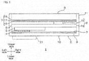
- the upper side on the plane of the sheet is "upper side” (one side in the first direction, one side in the thickness direction)
- the lower side on the plane of the sheet is “lower side” (the other side in the first direction, the other side in the thickness direction)
- the left side on the plane of the sheet is “left side” (one side in the second direction)
- the right side on the plane of the sheet is “right side” (the other side in the second direction)
- the further side in the paper thickness direction is "front side” (one side in the third direction)
- the nearer side in the paper thickness direction is “rear side” (the other side in the third direction).
- the directions are in conformity with the direction arrows shown in FIG. 1 .
- the directions are in conformity with the directions in FIG. 1 .
- a communication module 1 includes a housing 2, a sheet member 3 having thermal conductivity and electric insulation, a coil 4 as an element that generates induced electromotive force, a battery 5, a communication circuit 6, a heat-release sheet 7, and an image display device 8.
- the housing 2 is a box shape with its upper side open, and includes a base plate 10, and side walls 11 extending upwardly from the peripheral end edge of the base plate 10.
- the housing 2 accommodates the sheet member 3, the coil 4, the battery 5, the communication circuit 6, the heat-release sheet 7, and the image display device 8 inside.
- the base plate 10 has a generally rectangular shape extending in left-right directions when viewed from the top.
- the side wall 11 has a generally rectangular frame shape when viewed from the top, and is formed so that its up-down direction length (height) is about the same with or longer than the total height of the sheet member 3, the coil 4, the battery 5, the communication circuit 6, the heat-release sheet 7, and the image display device 8.
- the housing 2 is formed, for example, from resin and/or metal.
- thermoplastic resin for example, thermoplastic resin is used.
- thermoplastic resin include polycarbonate, acrylonitrile butadiene styrene copolymer (ABS), polyvinyl chloride, and acrylic resin.
- metal for example, aluminum, iron, copper, and stainless steel are used.
- the sheet member 3 has a generally rectangular shape extending in left-right directions when viewed from the top, as shown by the solid line in FIG. 1 and FIG. 2 , and is formed so as to be included in the inner circumferential edge of the side wall 11 when projected in up-down direction (thickness direction).
- the sheet member 3 is accommodated at the lowermost plane in the housing 2. To be specific, the sheet member 3 is disposed inside the housing 2 so as to be in contact with the upper face of the base plate 10 and the inner faces of the side wall 11.
- the sheet member 3 is formed, for example, from a thermal conductive resin composition containing thermal conductive particles and a resin component.
- Examples of the material that composes the thermal conductive particles include metal-nitrides such as boron nitride, aluminum nitride, silicon nitride, and gallium nitride; metal oxides such as silicon dioxide, aluminum oxide, magnesium oxide, titanium oxide, zinc oxide, tin oxide, copper oxide, and nickel oxide; hydroxides such as aluminum hydroxide, boehmite, magnesium hydroxide, calcium hydroxide, zinc hydroxide, silicic acid, iron hydroxide, copper hydroxide, and barium hydroxide; hydrated metal oxide such as zirconium oxide hydrate, tin oxide hydrate, basic magnesium carbonate, hydrotalcite, dawsonite, borax, and zinc borate; silicon carbide, calcium carbonate, barium titanate, and potassium titanate. These can be used singly, or two or more of these can be used.
- metal-nitrides such as boron nitride, aluminum nitride, silicon nitride, and gallium
- the thermal conductive particles have thermal conductivity and electric insulation.
- metal nitrides are used, more preferably, boron nitride is used in view of thermal conductivity and electric insulation.
- the shape of the thermal conductive particles is not particularly limited as long as they are particles (powder), and examples thereof include bulk shape, needle shape, and flat shape (including flake-like).
- examples of the bulk shape include spherical, cuboid, pulverized, or their variants.
- flat shape is used.
- the aspect ratio is, for example, 2 or more, preferably 4 or more, and for example, 1000 or less, preferably 200 or less.
- the thermal conductive particles have an average particle size (average of maximum length) of, for example, 1 ⁇ m or more, preferably 10 ⁇ m or more, and for example, 300 ⁇ m or less, preferably 100 ⁇ m or less.
- the average particle size of the thermal conductive particles is measured based on the particle size distribution measured by particle size distribution measurement method of laser scattering method, as a volume-based average particle size, to be more specific, as D50 value (cumulative 50% median diameter).
- the thermal conductive resin composition has a thermal conductive particle content based on volume (solid content excluding solvent (that is, thermal conductive particles, resin component, and thermosetting catalyst and other additives contained as necessary)) of, for example, 55% by volume or more, preferably 60% by volume or more, for example, 95% by volume or less, preferably 90% by volume or less.
- the mass content is, for example, 50 mass% or more, preferably 80 mass% or more, and for example, 98 mass% or less, preferably 95 mass% or less.
- the mass content in the above-described range allows for a sheet member 3 with excellent thermal conductivity.
- thermosetting resin any of the thermosetting resin and the thermoplastic resin can be contained, but preferably, thermosetting resin is contained.
- thermosetting resin examples include epoxy resin, phenol resin, amino resin, unsaturated polyester resin, polyurethane resin, silicone resin, urea resin, melamine resin, thermosetting polyimide resin, and diallyl phthalate resin.
- epoxy resin and phenol resin are used, more preferably, epoxy resin and phenol resin are used in combination.
- the epoxy resin examples include those epoxy resins that can be used, for example, as an adhesive composition, including bisphenol epoxy resin (particularly, bisphenol A epoxy resin, bisphenol F epoxy resin, bisphenol S epoxy resin, brominated bisphenol A epoxy resin, hydrogenated bisphenol A epoxy resin, bisphenol AF epoxy resin, etc.), phenol epoxy resin (particularly, phenol novolak epoxy resin, ortho-cresol novolak epoxy resin, etc.), biphenyl epoxy resin, naphthalene epoxy resin, fluorine epoxy resin, trishdroxy phenylmethane epoxy resin, and tetraphenylol ethane epoxy resin. Examples thereof also include hydantoin epoxy resin, trisglycidyl isocyanurate epoxy resin, and glycidylamine epoxy resin. These can be used singly, or can be used in combination of two or more.
- bisphenol epoxy resin particularly, bisphenol A epoxy resin, bisphenol F epoxy resin, bisphenol S epoxy resin, brominated bisphenol A epoxy resin, hydrogenated bisphenol
- epoxy resins preferably, bisphenol epoxy resin, more preferably, bisphenol A epoxy resin is used.
- the sheet member 3 achieves excellent heat resistance.
- the phenol resin is a curing agent for epoxy resin, and examples thereof include novolak phenol resins such as phenol novolak resin, phenol aralkyl resin, cresol novolak resin, tert-butylphenol novolak resin, and nonyl phenol novolak resin; resol phenol resin; and polyoxy styrene such as polyparaoxy styrene. These can be used singly, or can be used in combination of two or more.
- novolak phenol resins such as phenol novolak resin, phenol aralkyl resin, cresol novolak resin, tert-butylphenol novolak resin, and nonyl phenol novolak resin
- resol phenol resin resol phenol resin
- polyoxy styrene such as polyparaoxy styrene.
- novolak resin preferably, novolak resin, more preferably, phenol novolak resin, phenol aralkyl resin, even more preferably, phenol aralkyl resin is used.
- the epoxy resin content relative to 100 parts by mass of the resin component is, for example, 15 parts by mass or more, preferably 30 parts by mass or more, and for example, 70 parts by mass or less, preferably 50 parts by mass or less
- the phenol resin content relative to 100 parts by mass of the resin component is, for example, 5 parts by mass or more, preferably 15 parts by mass or more, and for example, 50 parts by mass or less, preferably 30 parts by mass or less.
- the epoxy resin content relative to 100 parts by mass of the resin component is, for example, 10 parts by mass or more, preferably 25 parts by mass or more, and for example, 50 parts by mass or less
- the phenol resin content relative to 100 parts by mass of the resin component is, for example, 10 parts by mass or more, preferably 25 parts by mass or more, and for example, 50 parts by mass or less.
- the epoxy resin content relative to 100 parts by mass of the resin component is, for example, 5 parts by mass or more, preferably 15 parts by mass or more, and for example, 30 parts by mass or less, and the phenol resin content relative to 100 parts by mass of the resin component is, for example, 15 parts by mass or more, preferably 35 parts by mass or more, and for example, 70 parts by mass or less.
- the epoxy equivalent when two types of epoxy resin are used is an epoxy equivalent of all epoxy resins obtained by multiplying the total amount of the epoxy resin by mass of the epoxy resins, and adding up these.
- the hydroxyl equivalent in the phenol resin relative to 1 equivalent of the epoxy group of epoxy resin is, for example, 0.2 equivalent or more, preferably 0.5 equivalent or more, and for example, 2.0 equivalent or less, preferably 1.2 equivalent or less.
- the amount of the hydroxyl group within the above-described range allows for excellent curing reaction of the sheet member 3 in semi-cured state, and also suppression of degradation.
- the resin component has a thermosetting resin content relative to 100 parts by mass of the resin component of, for example, 20 parts by mass or more, preferably 30 parts by mass or more, and for example, 90 parts by mass or less, preferably 80 parts by mass or less, more preferably 60 parts by mass or less.
- the resin component preferably contains acrylic resin, in addition to the thermosetting resin. That is, for the resin component, preferably, acrylic resin, epoxy resin, and phenol resin are used in combination.
- acrylic resin, epoxy resin, and phenol resin are used in combination.
- the resin component containing these resins allows for excellent thermal conductivity, electric insulation, and adhesiveness.
- acrylic resin examples include an acrylic polymer produced by polymerizing a monomer component of one or more (meth) acrylic acid alkyl ester having a straight chain or branched alkyl group.
- the "(meth) acryl” represents "acryl and/or methacryl”.
- alkyl group examples include an alkyl group having 1 to 20 carbon atoms such as a methyl group, ethyl group, propyl group, isopropyl group, n-butyl group, t-butyl group, isobutyl group, amyl group, isoamyl group, hexyl group, heptyl group, cyclohexyl group, 2-ethylhexyl group, octyl group, isooctyl group, nonyl group, isononyl group, decyl group, isodecyl group, undecyl group, lauryl group, tridecyl group, tetradecyl group, stearyl group, octadecyl group, and dodecyl group.
- an alkyl group having 1 to 6 carbon atoms is used.
- the acrylic polymer can be a copolymer of (meth) acrylic acid alkyl ester and other monomers.
- Examples of the other monomers include glycidyl group-containing monomers such as glycidyl acrylate and glycidyl methacrylate; carboxyl group-containing monomers such as acrylic acid, methacrylic acid, carboxyethyl acrylate, carboxypentyl acrylate, itaconic acid, maleic acid, fumaric acid, and crotonic acid; acid anhydride monomers such as maleic anhydride and itaconic anhydride; hydroxyl group-containing monomers such as 2-hydroxyethyl (meth)acrylate, 2-hydroxypropyl (meth)acrylate, 4-hydroxybutyl (meth)acrylate, 6-hydroxyhexyl (meth)acrylate, 8-hydroxyoctyl (meth)acrylate, 10-hydroxydecyl (meth)acrylate, 12-hydroxylauryl (meth)acrylate or (4-hydroxymethylcyclohexyl)-methylacrylate; sulfonic acid group-containing monomers such as
- glycidyl group-containing monomers carboxyl group-containing monomers, or hydroxyl group-containing monomers are used.
- the acrylic resin is a copolymer of (meth) acrylic acid alkyl ester and these other monomers, that is, when the acrylic resin has a glycidyl group, carboxyl group, or hydroxyl group, the sheet member 3 has excellent heat resistance.
- the mixing ratio (mass) of the other monomer relative to the copolymer is preferably 40 mass% or less.
- the acrylic resin has a weight average molecular weight of, for example, 1 ⁇ 10 5 or more, preferably 3 ⁇ 10 5 or more, and for example, 1 ⁇ 10 6 or less. Such a range allows for excellent adhesiveness and heat resistance of the sheet member 3.
- the weight average molecular weight is measured by gel permeation chromatography (GPC) based on polystyrene standard.
- the acrylic resin content relative to 100 parts by mass of resin component is, for example, 10 parts by mass or more, preferably 20 parts by mass or more, more preferably 40 parts by mass or more, and for example, 80 parts by mass or less, preferably 70 parts by mass or less.
- Such a range allows for excellent sheet moldability of the sheet member 3 and adhesiveness of the sheet member 3 in semi-cured state.
- the thermal conductive resin composition has a resin component content of, for example, 2 mass% or more, preferably 5 mass% or more, and for example, 50 mass% or less, preferably 15 mass% or less.
- the above-described range allows for excellent sheet moldability of the sheet member 3.
- the resin component can contain resin other than the thermosetting resin and acrylic resin.
- resin other than the thermosetting resin and acrylic resin for example, thermoplastic resin is used. These resins can be used singly or can be used in combination of two or more.
- thermoplastic resin examples include natural rubber, butyl rubber, isoprene rubber, chloroprene rubber, an ethylene-vinyl acetate copolymer, a copolymer, polybutadiene resin, polycarbonate resin, thermoplastic polyimide resin, polyamide resin (6-nylon, 6,6-nylon, etc.), phenoxy resin, saturated polyester resin (PET, PBT, etc.), polyamideimide resin, and fluorine resin.
- the thermal conductive resin composition (and also sheet member 3) preferably contains a thermosetting catalyst.
- thermosetting catalyst is not limited as long as the catalyst accelerates curing of the thermosetting resin by heating, and examples thereof include an imidazole compound, triphenylphosphine compound, triphenylborane compound, and amino group-containing compound.
- an imidazole compound is used.
- imidazole compound examples include 2-phenylimidazole (trade name; 2PZ), 2-ethyl-4-methylimidazole (trade name; 2E 4MZ), 2-methylimidazole (trade name; 2MZ), 2-undecylimidazole (trade name; C 11Z), 2-phenyl-4,5-dihydroxymethylimidazole (trade name; 2-PHZ), 2-phenyl-1H-imidazole 4,5-dimethanol (trade name; 2PHZ-PW), and 2,4-diamino-6-(2'-methylimidazolyl(1)') ethyl-s-triazine ⁇ isocyanuric acid adduct (trade name; 2MAOK-PW) (the above-described products are all manufactured by Shikoku Chemicals Corporation.).
- thermosetting catalyst can be, for example, spherical or ellipsoid.
- thermosetting catalyst can be used singly, or can be used in combination or two or more.
- the mixing ratio of the thermosetting catalyst relative to 100 parts by mass of the resin component is, for example, 0.2 parts by mass or more, preferably 0.3 parts by mass or more, and for example, 5 parts by mass or less, preferably 2 parts by mass or less.
- the thermal conductive resin composition can further contain, as necessary, other additives.
- additives include commercially available or known cross-linking agent and inorganic filler.
- the thermal conductive resin composition preferably does not substantially contain an electrically conductive material.
- Examples of the electrically conductive material include carbon, and metals such as gold, silver, and copper.
- the thermal conductive resin composition is prepared by mixing the above-described components at the above-described mixing ratio.
- the sheet member 3 can be produced, for example, by a preparation step, in which a solution of a thermal conductive resin composition is prepared by dissolving or dispersing the thermal conductive resin composition in the solvent; a drying step, in which the solution of the thermal conductive resin composition is applied on the surface of the release substrate and dried to produce a sheet member 3a in a semi-cured state; and a heat-pressing step, in which the plurality of semi-cured sheet members 3a are laminated and heat-pressed.
- a preparation step in which a solution of a thermal conductive resin composition is prepared by dissolving or dispersing the thermal conductive resin composition in the solvent
- a drying step in which the solution of the thermal conductive resin composition is applied on the surface of the release substrate and dried to produce a sheet member 3a in a semi-cured state
- a heat-pressing step in which the plurality of semi-cured sheet members 3a are laminated and heat-pressed.
- the thermal conductive resin composition is dissolved or dispersed in a solvent (preparation step).
- the solvent examples include organic solvents such as ketones including acetone and methyl ethyl ketone (MEK); esters such as ethyl acetate; amides such as N,N-dimethylformamide; and ethers such as propylene glycol monomethylether.
- organic solvents such as ketones including acetone and methyl ethyl ketone (MEK); esters such as ethyl acetate; amides such as N,N-dimethylformamide; and ethers such as propylene glycol monomethylether.
- water-based solvents such as water, and alcohols such as methanol, ethanol, propanol, and isopropanol.
- the thermal conductive resin composition solution has a solid content of, for example, 5 mass% or more, preferably 10 mass% or more, and for example, 50 mass% or less, preferably 20 mass% or less.
- the thermal conductive resin composition solution is prepared in this manner.
- the thermal conductive resin composition solution is applied on the surface of the release substrate and dried (drying step).
- Examples of the release substrate include a polyethylene terephthalate (PET) film, polyethylene film, polypropylene film, and paper.
- PET polyethylene terephthalate
- a surface treatment is given with, for example, a fluorine release agent, long-chain alkylacrylate release agent, and silicone release agent.
- the application method is not particularly limited, and for example, the application can be performed by doctor blade application method, roll application method, screen application method, and gravure application method.
- the drying conditions are as follows: the drying temperature is, for example, 70°C or more and 160°C or less, and the drying time is, for example, 1 minute or more and 5 minutes or less.
- the sheet member 3a in semi-cured state is produced in this manner.
- the sheet member 3a is in semi-cured state (B-stage state) at room temperature (to be specific, 25°C), and is a thermal conductive adhesive sheet having excellent adhesiveness.
- the average film thickness of the sheet member 3a is, for example, 500 ⁇ m or less, preferably 200 ⁇ m or less, and for example, 5 ⁇ m or more, preferably 50 ⁇ m or more.
- the produced sheet member 3a in semi-cured state was cut as necessary to produce a plurality of the sheet members 3a, and the plurality of sheet members 3a were laminated in the thickness direction. Thereafter, the plurality of sheet members 3a were heat-pressed with a heat-press in the thickness direction (heat-pressing step). The sheet member 3a in semi-cured state is cured by heat in this manner.
- the heat-pressing can be performed using a known press, and examples thereof include a parallel-plate press.
- the number of the sheet member 3a (semi-cured state) laminated is, for example, 1 layer or more, preferably 2 layers or more, and for example, 20 layers or less, preferably 5 layers or less. In this manner, the sheet member 3 can be adjusted to a desired thickness.
- the heating temperature is, for example, 80°C or more, preferably 100°C or more, and for example, 200°C or less, preferably 175°C or less.
- the heating time is, for example, 0.1 hours or more, preferably 0.2 hours or more, and for example, 24 hours or less, preferably 3 hours or less.
- the pressure is, for example, 10MPa or more, preferably 20MPa or more, and for example, 500MPa or less, preferably 200MPa or less.
- the sheet member 3a in semi-cured state is cured by heat, and the sheet member 3 in cured state (C stage state) is produced.
- the sheet member 3 has a thickness of, for example, 5 ⁇ m or more, preferably 50 ⁇ m or more, more preferably 100 ⁇ m or more, and for example, 500 ⁇ m or less, preferably 250 ⁇ m or less, more preferably 200 ⁇ m or less.
- the thermal conductive particles contained in the sheet member 3 are preferably arranged in the 2-dementional in-plane direction (front-rear-left-right directions)) of the sheet member, by performing the heat-pressing step. That is, preferably, the longitudinal direction (direction perpendicular to the thickness direction) of the flat thermal conductive particles are oriented so as to be along the surface direction of the sheet member 3.
- the sheet member 3 is excellent in thermal conductivity.
- the sheet member 3 has a thermal conductivity in the surface direction of, for example, 10 W/m ⁇ K or more, preferably 30 W/m ⁇ K or more, more preferably 40 W/m ⁇ K or more, and for example, 500 W/m ⁇ K or less, preferably 150 W/m ⁇ K or less.
- the thermal conductivity is measured by the laser flash method.
- the sheet member 3 has a volume resistivity of, for example, 1.0 x 10 12 ⁇ cm or more, preferably 1.0 ⁇ 10 14 ⁇ cm or more, more preferably 1.5 ⁇ 10 14 ⁇ cm or more, and for example, 1.0 ⁇ 10 18 ⁇ cm or less, preferably 1.5 ⁇ 10 16 ⁇ m or less.
- the volume resistivity is measured by dual-ring-electrode system.
- the sheet member 3 can be, for example, a single layer structure composed only of the sheet member 3, as shown with the solid line in FIG. 1 , or can be a two-layer structure in which the first adhesive layer 9 is laminated on the lower face of the sheet member 3, as shown with the phantom line in FIG. 1 .
- Examples of the adhesive that forms the first adhesive layer 9 include those known adhesives that are generally used for adhesives for a circuit board, and for example, an epoxy adhesive, polyimide adhesive, and acrylic adhesive are used.
- the first adhesive layer 9 is formed by applying the adhesive on the lower face of the sheet member 3.
- the first adhesive layer 9 can also be formed by bonding a commercially available double-coated tape formed with the adhesive on the lower face of the sheet member 3.
- the first adhesive layer 9 has the first adhesive layer 9
- the first adhesive layer 9 has a thickness of, for example, 1 ⁇ m or more, preferably 3 ⁇ m or more, and for example, 100 ⁇ m or less, preferably 30 ⁇ m or less.
- the coil 4 is an element that generates induced electromotive force by a wireless system, that is, an element that generates induced electromotive force by magnetic force generated by an external charger (non-contact power transmission device) that is not shown, and is disposed next to the upper side of the sheet member 3. To be specific, the coil 4 is interposed between the upper face of the sheet member 3 and the lower face of the battery 5, so as to be in contact with and face these.
- the coil 4 includes a loop coil portion 12, and a pair of connection portion 13 integrally formed at the free end portions of the loop coil portion 12.
- the loop coil portion 12 is, for example, spiral, and has a two-layer structure including an upper side coil portion and a lower side coil portion.
- the upper side coil portion and the lower side coil portion are disposed to face each other with an insulation intermediate sheet interposed therebetween, which is not shown, and a lead at the innermost side of the upper side coil portion is electrically connected to a lead at the innermost side of the lower side coil portion through a via hole, which is not shown.
- a space is provided between the leads that form the loop coil portion 12.
- connection portions 13 are formed continuously from the lead at the outermost side of the upper side coil portion and the lower side coil portion, and have a generally rectangular flat shape when viewed from the top.
- the connection portions 13 are connected to a battery 5 or a communication circuit 6.
- the battery 5 is disposed next to the upper side of the coil 4. To be specific, the battery 5 is interposed between the upper face of the coil 4 and the lower face of the communication circuit 6 (described later), and is disposed to face and make contact with these. The battery 5 is connected with the two connection portions 13, and electrically connected with the coil 4.
- the battery 5 has a generally rectangular thin plate shape when viewed from the top, and for example, is a known battery 5 used for mobile devices.
- the battery 5 is, for example, secondary batteries such as lithium ion batteries.
- the battery 5 has a size of about the half of the sheet member 3, and is disposed at the right end portion of the housing 2.
- the communication circuit 6 includes a circuit having a communication function, and for example, as shown in FIGs. 1 and 2 , includes a base substrate 14, a circuit pattern (not shown) disposed on the upper face of the base substrate 14, a CPU 15, and a circuit element (not shown).
- the base substrate 14 is formed into a generally rectangular shape when viewed from the top, and when projected in up-down direction, has generally the same shape as that of the sheet member 3, and is formed so as to be included inside the side wall 11.
- the base substrate 14 is formed, for example, from electrically non-conductive resin such as polyimide, polyester, polyethylene terephthalate, polyethylene naphthalate, and polycarbonate. Furthermore, a resin-covered substrate in which the surface of a ceramic substrate (alumina, aluminum nitride, silicon nitride, etc.) or a metal substrate (aluminum plate, etc.) is covered with an electrically non-conductive resin can also be used.
- electrically non-conductive resin such as polyimide, polyester, polyethylene terephthalate, polyethylene naphthalate, and polycarbonate.
- a resin-covered substrate in which the surface of a ceramic substrate (alumina, aluminum nitride, silicon nitride, etc.) or a metal substrate (aluminum plate, etc.) is covered with an electrically non-conductive resin can also be used.
- the circuit pattern is a wiring formed from, for example, conductors such as gold, silver, and copper, and is electrically connected with the coil 4 or the battery 5.
- the CPU 15 is a generally rectangular plate slightly smaller than the battery 5 when viewed from the top; is mounted on the upper face of the left end portion of the base substrate 14; and is electrically connected with the circuit pattern. To be specific, the CPU 15 is interposed between the upper face of the base substrate 14 and the lower face of the heat-release sheet 7, and is disposed to face and make contact with these.
- the circuit element is mounted on the upper face of the base substrate 14, and is electrically connected with the circuit pattern and the CPU 15.
- Examples of the circuit element include a condenser, resistor, and wireless communication unit.
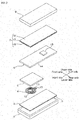
- the heat-release sheet 7 is formed generally shape when viewed from the top, as shown in FIG. 2 , and when projected in up-down direction, has generally the same shape as that of the sheet member 3, and is formed so as to be in frame of the side wall 11. To be specific, the heat-release sheet 7 is formed so as to have the same shape as that of the image display device 8 (described later) when viewed from the top.
- the heat-release sheet 7 includes an insulating layer 16, a heat conductive layer 17 laminated on the upper face of the insulating layer 16, and a second adhesive layer 18 laminated on the upper face of the heat conductive layer 17.
- the insulating layer 16, the heat conductive layer 17, and the second adhesive layer 18 are formed to be the same shape when viewed from the top.
- Examples of the insulating layer 16 include electrically non-conductive films such as a polyimide film, polyester film, polyethylene terephthalate (PET) film, polyethylene naphthalate film, and polycarbonate film.
- electrically non-conductive films such as a polyimide film, polyester film, polyethylene terephthalate (PET) film, polyethylene naphthalate film, and polycarbonate film.
- the insulating layer 16 has a thickness of, for example, 1 ⁇ m or more, preferably 5 ⁇ m or more, and for example, 50 ⁇ m or less, preferably 25 ⁇ m or less.
- Examples of the heat conductive layer 17 include a graphite sheet, and a metal film such as copper foil, silver foil, gold foil, and aluminum foil.
- a graphite sheet is used.
- the heat conductive layer 17 has a thickness of, for example, 1 ⁇ m or more, preferably 10 ⁇ m or more, and for example, 200 ⁇ m or less, preferably 100 ⁇ m or less.
- Examples of the adhesive that forms the second adhesive layer 18 include those adhesives given as examples of the first adhesive layer 9.
- the second adhesive layer 18 has a thickness of, for example, 1 ⁇ m or more, preferably 5 ⁇ m or more, and for example, 100 ⁇ m or less, preferably 50 ⁇ m or less.
- the image display device 8 has a generally rectangular thin box shape when viewed from the top, and is disposed next to the upper side of the heat-release sheet 7. To be specific, the image display device 8 is disposed to face the heat-release sheet 7 so as to make contact with the second adhesive layer 18.
- the image display device 8 is accommodated inside the housing 2 so that the upper face of the image display device 8 is flush with the upper end face of the side wall 11, and the peripheral end portion of the image display device 8 is in contact with the inside face of the side wall 11.
- Examples of the image display device 8 include a liquid crystal display device and an organic EL device.
- the communication module 1 can be produced by disposing the above-described components in the above-described order.
- the sheet member 3 When the sheet member 3 is disposed inside the housing 2, as shown in the solid line in FIG. 1 , the sheet member 3 can be disposed directly on the base plate 10. Furthermore, by bonding the sheet member 3a in semi-cured state to the housing 2, and curing it by heating, the sheet member 3 in cured state can be allowed to adhere to and disposed in the housing 2.
- the sheet member 3 can be allowed to adhere to and disposed to the base plate 10 with a known first adhesive layer 9.
- the coil 4 generates electric power by electromagnetic induction. That is, the communication module 1 can be charged wirelessly without wired charging. Then, the electric power generated by the coil 4 is charged to the battery 5, and then based on the electric power, the communication circuit 6 operates. The coil 4 generates heat at this time. The CPU 15 generates heat during the communication circuit 6 is in operation.
- the communication module 1 includes a heat-release sheet 7 disposed between the communication circuit 6 and the image display device 8. Therefore, the heat generated by the CPU 15 can be dissipated to the heat-release sheet 7, and can be efficiently released to the image display device 8 and to the outside.
- the communication module 1 includes a thermal conductive and electrically non-conductive sheet member 3 that is disposed between the housing 2 and the coil 4. Therefore, the heat generated by the coil 4 can be dissipated to the sheet member 3, and can be efficiently released to the housing 2 and to the outside.
- the sheet member 3 is electrically insulative, effects from the magnetic force from an external charger 21 can be reduced by the sheet member 3. As a result, reduction in induced electromotive force, and reduction in power transmission/reception efficiency in wireless charging can be suppressed.
- the communication module 1 can be suitably used for, for example, a small mobile device having a wireless charging function, to be specific, a mobile phone such as a smartphone, cordless phones, small personal computers, electric shaver, and electric toothbrushes.
- a small mobile device having a wireless charging function to be specific, a mobile phone such as a smartphone, cordless phones, small personal computers, electric shaver, and electric toothbrushes.
- the heat-release sheet 7 is disposed on the upper side of the communication circuit 6 in the embodiment of FIG. 1 , for example, the image display device 8 can be directly disposed on the upper side of the communication circuit 6 without disposing the heat-release sheet 7, although not shown.
- the heat-release sheet 7 is disposed on the upper side of the communication circuit 6. In this manner, the heat-release sheet 7 allows for the heat generated from the CPU 15 mounted on the communication circuit 6 to be efficiently dissipated and released.
- thermal conductive particles boron nitride particles (manufactured by DENKI KAGAKU KOGYO KABUSHIKI KAISHA, trade name "XGP", flat, average particle size 30 ⁇ m) were used.
- a thermal conductive resin composition was produced by mixing 1150 parts by mass (92 mass%) of thermal conductive particles, 50 parts by mass of acrylate ester polymer, 20 parts by mass of bisphenol A epoxy resin (1), 12 parts by mass of bisphenol A epoxy resin (2), 18 parts by mass of phenol aralkyl resin, and 0.5 parts by mass of thermosetting catalyst, so that the thermal conductive resin composition has a thermal conductive particle content of 65% by volume.
- a thermal conductive resin composition solution having a solid content concentration of 12 mass% was prepared by dissolving the thermal conductive resin composition in methyl ethyl ketone.
- the thermal conductive resin composition solution was applied on a release substrate (average thickness 50 ⁇ m) composed of a polyethylene terephthalate film treated with silicone for release using an applicator, and thereafter, dried at 130°C for 2 minutes.
- the sheet member 3a in semi-cured state (average thickness of only sheet member 3,120 ⁇ m) on which the release substrate was laminated was produced.
- the sheet member 3a (semi-cured state) was heat-pressed under conditions of 100MPa and 175°C for 30 minutes, thereby producing a sheet member 3 (cured state) having a thickness of 40 ⁇ m.
- the sheet member 3 was cut into a size of 5 cm ⁇ 5 cm.
- a housing 2 was removed from a commercially available wirelessly charging smartphone (that is, the communication module 1 shown in FIG. 1 without the sheet member 3) shown in FIG. 3 .
- the sheet member 3 produced as described above, and the double-coated tape 9 (first adhesive layer, acrylic adhesive, manufactured by Nitto Denko Corporation, trade name "No. 5610", 5 cm ⁇ 5 cm ⁇ thickness 10 ⁇ m) were disposed in order on a spiral coil 4 (peripheral circle diameter 4 cm, two-layer structure, inductance 10.5 ⁇ H, resistance 790 m ⁇ ) embedded in the smartphone. Then, the sheet member 3 on which the coil 4 was provided was attached again to the housing 2 with the first adhesive layer 9 interposed therebetween, thereby producing the communication module 1 in one embodiment of the present invention shown in FIG. 1 .
- the heat-release sheet 7 is a laminate of a PET film (thickness 10 ⁇ m), a graphite sheet (thickness 70 ⁇ m), and an acrylic pressure-sensitive adhesive (second adhesive layer, thickness 10 ⁇ m).
- a communication module 1 was produced in the same manner as in Example 1, except that in Example 1, two sheet members 3 a (semi-cured state) were produced, these sheet members 3 a (excluding release substrate) were laminated, heat-pressed under the conditions of 100MPa and 175°C for 30 minutes, and a sheet member 3 (cured state) having a thickness of 85 ⁇ m was produced.
- a communication module 1 was produced in the same manner as in Example 2, except that in Example 1, three sheet members 3a (semi-cured state) were laminated and a sheet member 3 (cured state) having a thickness of 130 ⁇ m was produced.
- a commercially available wireless charging smartphone shown in FIG. 3 was used as a communication module for Comparative Example 1.
- a communication module was produced (ref: FIG. 4 .) in the same manner as in Example 1, except that in Example 1, a graphite sheet 19 (manufactured by Panasonic Corporation, trade name "PGS", thickness 17 ⁇ m) was used instead of the sheet member 3.
- PPS graphite sheet 19
- the sheet member 3 and the graphite sheet 19 used in Examples and Comparative Examples were cut into a 2 cm square, and using a xenon flash analyzer (trade name "LFA 447 nanoflash", manufactured by Netzsch Japan K.K.), the thermal conductivity in the surface direction of the sheet was measured using the laser flash method. The results are shown in Table 1.
- the sheet member 3 and the graphite sheet 19 used in Examples and Comparative Examples were cut into a 10 cm square, and the volume resistivity (in conformity with JIS-K 6911) of the sheets was measured using a resistivity meter (trade name "Hiresta MCP-HT 450", manufactured by Mitsubishi Chemical Corporation) connected to a measurement unit box. The results are shown in Table 1.
- the component composed of the housing 2, double-coated tape 9, sheet member 3, and spiral coil 4 was removed from the communication module 1 produced in Examples, and a black tape (heat emissivity 0.95) was bonded to both sides (surface of the housing 2 and surface of the spiral coil 4) of the component, thereby producing a sample for heat-releasing evaluation.
- Comparative Example 1 the component composed of the housing 2 and the spiral coil 4 was removed, and a black tape (heat emissivity 0.95) was bonded to both sides of the component, thereby producing a sample for heat-releasing evaluation for Comparative Example 1.
- Comparative Example 2 the component composed of the housing 2, double-coated tape 9, graphite sheet 19, and spiral coil 4 was removed, and a black tape (heat emissivity 0.95) was bonded to both sides of the component, thereby producing a sample for heat-releasing evaluation.
- the spiral coil 4 (same as the above-described) was used as a power transmission coil 4a and a power receiving coil 4b, and a circuit shown in FIG. 5 was made. A gap of 5 mm was there between the power transmission coil 4a and the power receiving coil 4b.
- the sheet member 3 produced in Examples was disposed between the power transmission coil 4a and the power receiving coil 4b.
- Example 1 Example 2 Example 3 Comparative Example 1 Comparative Example 2 Sheet member Thickness ( ⁇ m) 40 85 130 - 17 Thermal conductivity (W/m ⁇ K) 40 40 40 - 100 Volume resistivity ( ⁇ cm) 2.5 ⁇ 10 15 3.6 ⁇ 10 15 3.8 ⁇ 10 15 - 5.0 ⁇ 10 -5 Heat-releasing characteristics Housing surface temperature (°C) 48.2 46.3 43.3 54.4 54.5 Temperature change *(°C) -6.2 -8.1 -11.1 0.1 Transmission/ reception efficiency Received electric power (W) 7.9 7.8 8.0 8.0 6.0 Efficiency (%) 66 65 67 67 50 *Shows temperature difference from the housing surface temperature in Comparative Example 1
- the communication module of the present invention can be suitably used, for example, for a small mobile device including wireless charging functions.
Abstract
Description
- The present invention relates to a communication module, in particular, to a communication module such as mobile devices.
- Conventionally, in a communication module such as mobile devices, it has been demanded that heat generated from a heat source such as CPU be released efficiently from the housing to the outside.
- For example, Non-Patent
Document - Meanwhile, recently, a wireless charging mobile device including a wireless charging function using electromagnetic induction in a small mobile device represented by smartphones is in wide use.
- The wireless charging mobile device includes, for example, a housing, a coil embedded in the housing side and generates an electromotive force induced by magnetic force received from an external charger, a battery electrically connected to the coil, a communication circuit, and an image display device.
- In the wireless charging device as well, a graphite sheet disposed between the communication circuit and the image display device is included as a heat-release means.
-
- Non-Patent Document 1: Mutsuaki Murakami, "NEW DIAMOND" Vol.29 No. 1 (2013)
- Non-Patent Document 2: Tomoyuki Sugimoto, et al., "aluminum" vol. 18, no. 80 (2011)
- However, in the wireless charging mobile device, a coil is mounted as a heat source in addition to the CPU, and therefore more heat-releasing characteristics are demanded.
- Therefore, there has been examined that a graphite sheet is further disposed between the housing and the coil.
- However, when a graphite sheet is disposed between the housing and the coil, strong magnetic force is applied to the graphite, an electrically conductive material, and as a result, disadvantages such as heat generation from graphite, effects on electromagnetic induction, and reduction in charging efficiency.
- An object of the present invention is to provide a communication module with improved heat-releasing characteristics and suppression in reduction in power transmission/reception efficiency in wireless charging.
- A communication module of the present invention includes a housing, an element disposed in the housing and generates induced electromotive force by a wireless system, a communication circuit that operates based on electric power generated by the element, and a sheet member disposed between the housing and the element and having thermal conductivity and electric insulation.
- In the communication module of the present invention, it is preferable that the sheet member is formed from a resin composition containing thermal conductive particles and a resin component.
- In the communication module of the present invention, it is preferable that the thermal conductive particles are boron nitride.
- In the communication module of the present invention, it is preferable that the boron nitride has a flat shape.
- In the communication module of the present invention, it is preferable that the resin component contains epoxy resin, phenol resin, and acrylic resin.
- In the communication module of the present invention, it is preferable that the sheet member has a thermal conductivity in the surface direction of 30 W/m·K or more.
- It is preferable that the communication module of the present invention is a mobile device.
- With the communication module of the present invention, heat-releasing characteristics are excellent, and reduction in power transmission/reception efficiency in wireless charging is suppressed.
-
-
FIG. 1 shows a cross-sectional view of a communication module of the present invention in an embodiment. -
FIG. 2 shows an exploded perspective view of the communication module in the embodiment ofFIG. 1 . -
FIG. 3 shows a cross-sectional view of a communication module of Comparative Example 1. -
FIG. 4 shows a cross-sectional view of a communication module of Comparative Example 2. -
FIG. 5 shows a schematic view of an examination device for power transmission/reception efficiency evaluation conducted in Examples. - In
FIG. 1 , the upper side on the plane of the sheet is "upper side" (one side in the first direction, one side in the thickness direction), the lower side on the plane of the sheet is "lower side" (the other side in the first direction, the other side in the thickness direction), the left side on the plane of the sheet is "left side" (one side in the second direction), the right side on the plane of the sheet is "right side" (the other side in the second direction), the further side in the paper thickness direction is "front side" (one side in the third direction), and the nearer side in the paper thickness direction is "rear side" (the other side in the third direction). To be specific, the directions are in conformity with the direction arrows shown inFIG. 1 . In figures other thanFIG. 1 , the directions are in conformity with the directions inFIG. 1 . - As shown in
FIGs. 1 and2 , acommunication module 1 includes ahousing 2, asheet member 3 having thermal conductivity and electric insulation, acoil 4 as an element that generates induced electromotive force, abattery 5, a communication circuit 6, a heat-release sheet 7, and animage display device 8. - The
housing 2 is a box shape with its upper side open, and includes abase plate 10, andside walls 11 extending upwardly from the peripheral end edge of thebase plate 10. - The
housing 2 accommodates thesheet member 3, thecoil 4, thebattery 5, the communication circuit 6, the heat-release sheet 7, and theimage display device 8 inside. - The
base plate 10 has a generally rectangular shape extending in left-right directions when viewed from the top. - The
side wall 11 has a generally rectangular frame shape when viewed from the top, and is formed so that its up-down direction length (height) is about the same with or longer than the total height of thesheet member 3, thecoil 4, thebattery 5, the communication circuit 6, the heat-release sheet 7, and theimage display device 8. - The
housing 2 is formed, for example, from resin and/or metal. - For the resin, for example, thermoplastic resin is used. Examples of the thermoplastic resin include polycarbonate, acrylonitrile butadiene styrene copolymer (ABS), polyvinyl chloride, and acrylic resin.
- For the metal, for example, aluminum, iron, copper, and stainless steel are used.
- The
sheet member 3 has a generally rectangular shape extending in left-right directions when viewed from the top, as shown by the solid line inFIG. 1 andFIG. 2 , and is formed so as to be included in the inner circumferential edge of theside wall 11 when projected in up-down direction (thickness direction). - The
sheet member 3 is accommodated at the lowermost plane in thehousing 2. To be specific, thesheet member 3 is disposed inside thehousing 2 so as to be in contact with the upper face of thebase plate 10 and the inner faces of theside wall 11. - The
sheet member 3 is formed, for example, from a thermal conductive resin composition containing thermal conductive particles and a resin component. - Examples of the material that composes the thermal conductive particles include metal-nitrides such as boron nitride, aluminum nitride, silicon nitride, and gallium nitride; metal oxides such as silicon dioxide, aluminum oxide, magnesium oxide, titanium oxide, zinc oxide, tin oxide, copper oxide, and nickel oxide; hydroxides such as aluminum hydroxide, boehmite, magnesium hydroxide, calcium hydroxide, zinc hydroxide, silicic acid, iron hydroxide, copper hydroxide, and barium hydroxide; hydrated metal oxide such as zirconium oxide hydrate, tin oxide hydrate, basic magnesium carbonate, hydrotalcite, dawsonite, borax, and zinc borate; silicon carbide, calcium carbonate, barium titanate, and potassium titanate. These can be used singly, or two or more of these can be used.
- The thermal conductive particles have thermal conductivity and electric insulation.
- Preferably, metal nitrides are used, more preferably, boron nitride is used in view of thermal conductivity and electric insulation.
- The shape of the thermal conductive particles is not particularly limited as long as they are particles (powder), and examples thereof include bulk shape, needle shape, and flat shape (including flake-like). Examples of the bulk shape include spherical, cuboid, pulverized, or their variants. In view of thermal conductivity, preferably, flat shape is used.
- When the particles are flat, the aspect ratio is, for example, 2 or more, preferably 4 or more, and for example, 1000 or less, preferably 200 or less.
- The thermal conductive particles have an average particle size (average of maximum length) of, for example, 1 µm or more, preferably 10 µm or more, and for example, 300 µm or less, preferably 100 µm or less.
- The average particle size of the thermal conductive particles is measured based on the particle size distribution measured by particle size distribution measurement method of laser scattering method, as a volume-based average particle size, to be more specific, as D50 value (cumulative 50% median diameter).
- The thermal conductive resin composition has a thermal conductive particle content based on volume (solid content excluding solvent (that is, thermal conductive particles, resin component, and thermosetting catalyst and other additives contained as necessary)) of, for example, 55% by volume or more, preferably 60% by volume or more, for example, 95% by volume or less, preferably 90% by volume or less. The mass content is, for example, 50 mass% or more, preferably 80 mass% or more, and for example, 98 mass% or less, preferably 95 mass% or less. The mass content in the above-described range allows for a
sheet member 3 with excellent thermal conductivity. - For the resin component, any of the thermosetting resin and the thermoplastic resin can be contained, but preferably, thermosetting resin is contained.
- Examples of the thermosetting resin include epoxy resin, phenol resin, amino resin, unsaturated polyester resin, polyurethane resin, silicone resin, urea resin, melamine resin, thermosetting polyimide resin, and diallyl phthalate resin. Preferably, epoxy resin and phenol resin are used, more preferably, epoxy resin and phenol resin are used in combination.
- Examples of the epoxy resin include those epoxy resins that can be used, for example, as an adhesive composition, including bisphenol epoxy resin (particularly, bisphenol A epoxy resin, bisphenol F epoxy resin, bisphenol S epoxy resin, brominated bisphenol A epoxy resin, hydrogenated bisphenol A epoxy resin, bisphenol AF epoxy resin, etc.), phenol epoxy resin (particularly, phenol novolak epoxy resin, ortho-cresol novolak epoxy resin, etc.), biphenyl epoxy resin, naphthalene epoxy resin, fluorine epoxy resin, trishdroxy phenylmethane epoxy resin, and tetraphenylol ethane epoxy resin. Examples thereof also include hydantoin epoxy resin, trisglycidyl isocyanurate epoxy resin, and glycidylamine epoxy resin. These can be used singly, or can be used in combination of two or more.
- Of these examples of epoxy resins, preferably, bisphenol epoxy resin, more preferably, bisphenol A epoxy resin is used.
- By containing epoxy resin, excellent reactivity with phenol resin can be achieved, and as a result, the
sheet member 3 achieves excellent heat resistance. - The phenol resin is a curing agent for epoxy resin, and examples thereof include novolak phenol resins such as phenol novolak resin, phenol aralkyl resin, cresol novolak resin, tert-butylphenol novolak resin, and nonyl phenol novolak resin; resol phenol resin; and polyoxy styrene such as polyparaoxy styrene. These can be used singly, or can be used in combination of two or more.
- Of these examples of phenol resins, preferably, novolak resin, more preferably, phenol novolak resin, phenol aralkyl resin, even more preferably, phenol aralkyl resin is used.
- When the hydroxyl equivalent of phenol resin relative to 100 g/eq of epoxy equivalent of the epoxy resin is 1 g/eq or more and less than 100 g/eq, the epoxy resin content relative to 100 parts by mass of the resin component is, for example, 15 parts by mass or more, preferably 30 parts by mass or more, and for example, 70 parts by mass or less, preferably 50 parts by mass or less, and the phenol resin content relative to 100 parts by mass of the resin component is, for example, 5 parts by mass or more, preferably 15 parts by mass or more, and for example, 50 parts by mass or less, preferably 30 parts by mass or less.
- When the hydroxyl equivalent of the phenol resin relative to 100 g/eq of epoxy equivalent of the epoxy resin is 100 g/eq or more and less than 200 g/eq, the epoxy resin content relative to 100 parts by mass of the resin component is, for example, 10 parts by mass or more, preferably 25 parts by mass or more, and for example, 50 parts by mass or less, and the phenol resin content relative to 100 parts by mass of the resin component is, for example, 10 parts by mass or more, preferably 25 parts by mass or more, and for example, 50 parts by mass or less.
- When the hydroxyl equivalent of the phenol resin relative to 100 g/eq of epoxy equivalent of the epoxy resin is 200 g/eq or more and 1000 g/eq or less, the epoxy resin content relative to 100 parts by mass of the resin component is, for example, 5 parts by mass or more, preferably 15 parts by mass or more, and for example, 30 parts by mass or less, and the phenol resin content relative to 100 parts by mass of the resin component is, for example, 15 parts by mass or more, preferably 35 parts by mass or more, and for example, 70 parts by mass or less.
- The epoxy equivalent when two types of epoxy resin are used is an epoxy equivalent of all epoxy resins obtained by multiplying the total amount of the epoxy resin by mass of the epoxy resins, and adding up these.
- The hydroxyl equivalent in the phenol resin relative to 1 equivalent of the epoxy group of epoxy resin is, for example, 0.2 equivalent or more, preferably 0.5 equivalent or more, and for example, 2.0 equivalent or less, preferably 1.2 equivalent or less. The amount of the hydroxyl group within the above-described range allows for excellent curing reaction of the
sheet member 3 in semi-cured state, and also suppression of degradation. - The resin component has a thermosetting resin content relative to 100 parts by mass of the resin component of, for example, 20 parts by mass or more, preferably 30 parts by mass or more, and for example, 90 parts by mass or less, preferably 80 parts by mass or less, more preferably 60 parts by mass or less.
- The resin component preferably contains acrylic resin, in addition to the thermosetting resin. That is, for the resin component, preferably, acrylic resin, epoxy resin, and phenol resin are used in combination. The resin component containing these resins allows for excellent thermal conductivity, electric insulation, and adhesiveness.
- Examples of the acrylic resin include an acrylic polymer produced by polymerizing a monomer component of one or more (meth) acrylic acid alkyl ester having a straight chain or branched alkyl group. The "(meth) acryl" represents "acryl and/or methacryl".
- Examples of the alkyl group include an alkyl group having 1 to 20 carbon atoms such as a methyl group, ethyl group, propyl group, isopropyl group, n-butyl group, t-butyl group, isobutyl group, amyl group, isoamyl group, hexyl group, heptyl group, cyclohexyl group, 2-ethylhexyl group, octyl group, isooctyl group, nonyl group, isononyl group, decyl group, isodecyl group, undecyl group, lauryl group, tridecyl group, tetradecyl group, stearyl group, octadecyl group, and dodecyl group. Preferably, an alkyl group having 1 to 6 carbon atoms is used.
- The acrylic polymer can be a copolymer of (meth) acrylic acid alkyl ester and other monomers.
- Examples of the other monomers include glycidyl group-containing monomers such as glycidyl acrylate and glycidyl methacrylate; carboxyl group-containing monomers such as acrylic acid, methacrylic acid, carboxyethyl acrylate, carboxypentyl acrylate, itaconic acid, maleic acid, fumaric acid, and crotonic acid; acid anhydride monomers such as maleic anhydride and itaconic anhydride; hydroxyl group-containing monomers such as 2-hydroxyethyl (meth)acrylate, 2-hydroxypropyl (meth)acrylate, 4-hydroxybutyl (meth)acrylate, 6-hydroxyhexyl (meth)acrylate, 8-hydroxyoctyl (meth)acrylate, 10-hydroxydecyl (meth)acrylate, 12-hydroxylauryl (meth)acrylate or (4-hydroxymethylcyclohexyl)-methylacrylate; sulfonic acid group-containing monomers such as styrene sulfonic acid, allyl sulfonic acid, 2-(meth) acrylamide-2-methylpropane sulfonic acid, (meth) acrylamide propane sulfonic acid, sulfopropyl (meth) acrylate, and (meth) acryloyloxynaphthalene sulfonic acid; phosphoric acid group-containing monomers such as 2-hydroxyethylacryloyl phosphate; and a styrene monomer and acrylonitrile.
- Among these, preferably, glycidyl group-containing monomers, carboxyl group-containing monomers, or hydroxyl group-containing monomers are used. When the acrylic resin is a copolymer of (meth) acrylic acid alkyl ester and these other monomers, that is, when the acrylic resin has a glycidyl group, carboxyl group, or hydroxyl group, the
sheet member 3 has excellent heat resistance. - When the acrylic resin is a copolymer of (meth) acrylic acid alkyl ester and other monomers, the mixing ratio (mass) of the other monomer relative to the copolymer is preferably 40 mass% or less.
- The acrylic resin has a weight average molecular weight of, for example, 1 × 10⁵ or more, preferably 3 × 10⁵ or more, and for example, 1 × 10⁶ or less. Such a range allows for excellent adhesiveness and heat resistance of the
sheet member 3. The weight average molecular weight is measured by gel permeation chromatography (GPC) based on polystyrene standard. - When the resin component contains acrylic resin, the acrylic resin content relative to 100 parts by mass of resin component is, for example, 10 parts by mass or more, preferably 20 parts by mass or more, more preferably 40 parts by mass or more, and for example, 80 parts by mass or less, preferably 70 parts by mass or less. Such a range allows for excellent sheet moldability of the
sheet member 3 and adhesiveness of thesheet member 3 in semi-cured state. - The thermal conductive resin composition has a resin component content of, for example, 2 mass% or more, preferably 5 mass% or more, and for example, 50 mass% or less, preferably 15 mass% or less. The above-described range allows for excellent sheet moldability of the
sheet member 3. - The resin component can contain resin other than the thermosetting resin and acrylic resin. For the resin other than the thermosetting resin and acrylic resin, for example, thermoplastic resin is used. These resins can be used singly or can be used in combination of two or more.
- Examples of the thermoplastic resin include natural rubber, butyl rubber, isoprene rubber, chloroprene rubber, an ethylene-vinyl acetate copolymer, a copolymer, polybutadiene resin, polycarbonate resin, thermoplastic polyimide resin, polyamide resin (6-nylon, 6,6-nylon, etc.), phenoxy resin, saturated polyester resin (PET, PBT, etc.), polyamideimide resin, and fluorine resin.
- The thermal conductive resin composition (and also sheet member 3) preferably contains a thermosetting catalyst.
- The thermosetting catalyst is not limited as long as the catalyst accelerates curing of the thermosetting resin by heating, and examples thereof include an imidazole compound, triphenylphosphine compound, triphenylborane compound, and amino group-containing compound. Preferably, an imidazole compound is used.
- Examples of the imidazole compound include 2-phenylimidazole (trade name; 2PZ), 2-ethyl-4-methylimidazole (trade name; 2E 4MZ), 2-methylimidazole (trade name; 2MZ), 2-undecylimidazole (trade name; C 11Z), 2-phenyl-4,5-dihydroxymethylimidazole (trade name; 2-PHZ), 2-phenyl-1H-
imidazole 4,5-dimethanol (trade name; 2PHZ-PW), and 2,4-diamino-6-(2'-methylimidazolyl(1)') ethyl-s-triazine·isocyanuric acid adduct (trade name; 2MAOK-PW) (the above-described products are all manufactured by Shikoku Chemicals Corporation.). - The shape of the thermosetting catalyst can be, for example, spherical or ellipsoid.
- The thermosetting catalyst can be used singly, or can be used in combination or two or more.
- The mixing ratio of the thermosetting catalyst relative to 100 parts by mass of the resin component is, for example, 0.2 parts by mass or more, preferably 0.3 parts by mass or more, and for example, 5 parts by mass or less, preferably 2 parts by mass or less.
- The thermal conductive resin composition can further contain, as necessary, other additives. Examples of the additive include commercially available or known cross-linking agent and inorganic filler.
- The thermal conductive resin composition preferably does not substantially contain an electrically conductive material.
- Examples of the electrically conductive material include carbon, and metals such as gold, silver, and copper.
- The thermal conductive resin composition is prepared by mixing the above-described components at the above-described mixing ratio.
- The
sheet member 3 can be produced, for example, by a preparation step, in which a solution of a thermal conductive resin composition is prepared by dissolving or dispersing the thermal conductive resin composition in the solvent; a drying step, in which the solution of the thermal conductive resin composition is applied on the surface of the release substrate and dried to produce a sheet member 3a in a semi-cured state; and a heat-pressing step, in which the plurality of semi-cured sheet members 3a are laminated and heat-pressed. - First, the thermal conductive resin composition is dissolved or dispersed in a solvent (preparation step).
- Examples of the solvent include organic solvents such as ketones including acetone and methyl ethyl ketone (MEK); esters such as ethyl acetate; amides such as N,N-dimethylformamide; and ethers such as propylene glycol monomethylether. Examples of the solvent also include water-based solvents such as water, and alcohols such as methanol, ethanol, propanol, and isopropanol.
- The thermal conductive resin composition solution has a solid content of, for example, 5 mass% or more, preferably 10 mass% or more, and for example, 50 mass% or less, preferably 20 mass% or less.
- The thermal conductive resin composition solution is prepared in this manner.
- Then, the thermal conductive resin composition solution is applied on the surface of the release substrate and dried (drying step).
- Examples of the release substrate include a polyethylene terephthalate (PET) film, polyethylene film, polypropylene film, and paper. To the surface of these examples of the release substrate, a surface treatment is given with, for example, a fluorine release agent, long-chain alkylacrylate release agent, and silicone release agent.
- The application method is not particularly limited, and for example, the application can be performed by doctor blade application method, roll application method, screen application method, and gravure application method.
- The drying conditions are as follows: the drying temperature is, for example, 70°C or more and 160°C or less, and the drying time is, for example, 1 minute or more and 5 minutes or less.
- The sheet member 3a in semi-cured state is produced in this manner.
- The sheet member 3a is in semi-cured state (B-stage state) at room temperature (to be specific, 25°C), and is a thermal conductive adhesive sheet having excellent adhesiveness.
- The average film thickness of the sheet member 3a (semi-cured state) is, for example, 500 µm or less, preferably 200 µm or less, and for example, 5 µm or more, preferably 50 µm or more.
- Then, the produced sheet member 3a in semi-cured state was cut as necessary to produce a plurality of the sheet members 3a, and the plurality of sheet members 3a were laminated in the thickness direction. Thereafter, the plurality of sheet members 3a were heat-pressed with a heat-press in the thickness direction (heat-pressing step). The sheet member 3a in semi-cured state is cured by heat in this manner.
- The heat-pressing can be performed using a known press, and examples thereof include a parallel-plate press.
- The number of the sheet member 3a (semi-cured state) laminated is, for example, 1 layer or more, preferably 2 layers or more, and for example, 20 layers or less, preferably 5 layers or less. In this manner, the
sheet member 3 can be adjusted to a desired thickness. - The heating temperature is, for example, 80°C or more, preferably 100°C or more, and for example, 200°C or less, preferably 175°C or less.
- The heating time is, for example, 0.1 hours or more, preferably 0.2 hours or more, and for example, 24 hours or less, preferably 3 hours or less.
- The pressure is, for example, 10MPa or more, preferably 20MPa or more, and for example, 500MPa or less, preferably 200MPa or less.
- In this manner, the sheet member 3a in semi-cured state is cured by heat, and the
sheet member 3 in cured state (C stage state) is produced. - The
sheet member 3 has a thickness of, for example, 5 µm or more, preferably 50 µm or more, more preferably 100 µm or more, and for example, 500 µm or less, preferably 250 µm or less, more preferably 200 µm or less. - In the
sheet member 3, the thermal conductive particles contained in thesheet member 3 are preferably arranged in the 2-dementional in-plane direction (front-rear-left-right directions)) of the sheet member, by performing the heat-pressing step. That is, preferably, the longitudinal direction (direction perpendicular to the thickness direction) of the flat thermal conductive particles are oriented so as to be along the surface direction of thesheet member 3. Thus, thesheet member 3 is excellent in thermal conductivity. - The
sheet member 3 has a thermal conductivity in the surface direction of, for example, 10 W/m·K or more, preferably 30 W/m·K or more, more preferably 40 W/m·K or more, and for example, 500 W/m·K or less, preferably 150 W/m·K or less. - The thermal conductivity is measured by the laser flash method.
- The
sheet member 3 has a volume resistivity of, for example, 1.0 x 10¹²Ω·cm or more, preferably 1.0 × 10¹⁴Ω·cm or more, more preferably 1.5 × 10¹⁴Ω·cm or more, and for example, 1.0 × 10¹⁸Ω·cm or less, preferably 1.5 × 10¹⁶Ω·m or less. - The volume resistivity is measured by dual-ring-electrode system.
- The
sheet member 3 can be, for example, a single layer structure composed only of thesheet member 3, as shown with the solid line inFIG. 1 , or can be a two-layer structure in which the firstadhesive layer 9 is laminated on the lower face of thesheet member 3, as shown with the phantom line inFIG. 1 . - Examples of the adhesive that forms the first
adhesive layer 9 include those known adhesives that are generally used for adhesives for a circuit board, and for example, an epoxy adhesive, polyimide adhesive, and acrylic adhesive are used. - The first
adhesive layer 9 is formed by applying the adhesive on the lower face of thesheet member 3. The firstadhesive layer 9 can also be formed by bonding a commercially available double-coated tape formed with the adhesive on the lower face of thesheet member 3. - When the first
adhesive layer 9 has the firstadhesive layer 9, the firstadhesive layer 9 has a thickness of, for example, 1 µm or more, preferably 3 µm or more, and for example, 100 µm or less, preferably 30 µm or less. - The
coil 4 is an element that generates induced electromotive force by a wireless system, that is, an element that generates induced electromotive force by magnetic force generated by an external charger (non-contact power transmission device) that is not shown, and is disposed next to the upper side of thesheet member 3. To be specific, thecoil 4 is interposed between the upper face of thesheet member 3 and the lower face of thebattery 5, so as to be in contact with and face these. - The
coil 4 includes aloop coil portion 12, and a pair ofconnection portion 13 integrally formed at the free end portions of theloop coil portion 12. - The
loop coil portion 12 is, for example, spiral, and has a two-layer structure including an upper side coil portion and a lower side coil portion. The upper side coil portion and the lower side coil portion are disposed to face each other with an insulation intermediate sheet interposed therebetween, which is not shown, and a lead at the innermost side of the upper side coil portion is electrically connected to a lead at the innermost side of the lower side coil portion through a via hole, which is not shown. A space is provided between the leads that form theloop coil portion 12. - The two
connection portions 13 are formed continuously from the lead at the outermost side of the upper side coil portion and the lower side coil portion, and have a generally rectangular flat shape when viewed from the top. Theconnection portions 13 are connected to abattery 5 or a communication circuit 6. - The
battery 5 is disposed next to the upper side of thecoil 4. To be specific, thebattery 5 is interposed between the upper face of thecoil 4 and the lower face of the communication circuit 6 (described later), and is disposed to face and make contact with these. Thebattery 5 is connected with the twoconnection portions 13, and electrically connected with thecoil 4. - The
battery 5 has a generally rectangular thin plate shape when viewed from the top, and for example, is a knownbattery 5 used for mobile devices. To be specific, thebattery 5 is, for example, secondary batteries such as lithium ion batteries. - The
battery 5 has a size of about the half of thesheet member 3, and is disposed at the right end portion of thehousing 2. - The communication circuit 6 includes a circuit having a communication function, and for example, as shown in
FIGs. 1 and2 , includes abase substrate 14, a circuit pattern (not shown) disposed on the upper face of thebase substrate 14, aCPU 15, and a circuit element (not shown). - The
base substrate 14 is formed into a generally rectangular shape when viewed from the top, and when projected in up-down direction, has generally the same shape as that of thesheet member 3, and is formed so as to be included inside theside wall 11. - The
base substrate 14 is formed, for example, from electrically non-conductive resin such as polyimide, polyester, polyethylene terephthalate, polyethylene naphthalate, and polycarbonate. Furthermore, a resin-covered substrate in which the surface of a ceramic substrate (alumina, aluminum nitride, silicon nitride, etc.) or a metal substrate (aluminum plate, etc.) is covered with an electrically non-conductive resin can also be used. - The circuit pattern is a wiring formed from, for example, conductors such as gold, silver, and copper, and is electrically connected with the
coil 4 or thebattery 5. - The
CPU 15 is a generally rectangular plate slightly smaller than thebattery 5 when viewed from the top; is mounted on the upper face of the left end portion of thebase substrate 14; and is electrically connected with the circuit pattern. To be specific, theCPU 15 is interposed between the upper face of thebase substrate 14 and the lower face of the heat-release sheet 7, and is disposed to face and make contact with these. - The circuit element is mounted on the upper face of the
base substrate 14, and is electrically connected with the circuit pattern and theCPU 15. Examples of the circuit element include a condenser, resistor, and wireless communication unit. - The heat-
release sheet 7 is formed generally shape when viewed from the top, as shown inFIG. 2 , and when projected in up-down direction, has generally the same shape as that of thesheet member 3, and is formed so as to be in frame of theside wall 11. To be specific, the heat-release sheet 7 is formed so as to have the same shape as that of the image display device 8 (described later) when viewed from the top. - The heat-
release sheet 7 includes an insulatinglayer 16, a heatconductive layer 17 laminated on the upper face of the insulatinglayer 16, and a secondadhesive layer 18 laminated on the upper face of the heatconductive layer 17. The insulatinglayer 16, the heatconductive layer 17, and the secondadhesive layer 18 are formed to be the same shape when viewed from the top. - Examples of the insulating
layer 16 include electrically non-conductive films such as a polyimide film, polyester film, polyethylene terephthalate (PET) film, polyethylene naphthalate film, and polycarbonate film. - The insulating
layer 16 has a thickness of, for example, 1 µm or more, preferably 5 µm or more, and for example, 50 µm or less, preferably 25 µm or less. - Examples of the heat
conductive layer 17 include a graphite sheet, and a metal film such as copper foil, silver foil, gold foil, and aluminum foil. Preferably, a graphite sheet is used. - The heat
conductive layer 17 has a thickness of, for example, 1 µm or more, preferably 10 µm or more, and for example, 200 µm or less, preferably 100 µm or less. - Examples of the adhesive that forms the second
adhesive layer 18 include those adhesives given as examples of the firstadhesive layer 9. - The second
adhesive layer 18 has a thickness of, for example, 1 µm or more, preferably 5 µm or more, and for example, 100 µm or less, preferably 50 µm or less. - The
image display device 8 has a generally rectangular thin box shape when viewed from the top, and is disposed next to the upper side of the heat-release sheet 7. To be specific, theimage display device 8 is disposed to face the heat-release sheet 7 so as to make contact with the secondadhesive layer 18. Theimage display device 8 is accommodated inside thehousing 2 so that the upper face of theimage display device 8 is flush with the upper end face of theside wall 11, and the peripheral end portion of theimage display device 8 is in contact with the inside face of theside wall 11. - Examples of the
image display device 8 include a liquid crystal display device and an organic EL device. - The
communication module 1 can be produced by disposing the above-described components in the above-described order. - When the
sheet member 3 is disposed inside thehousing 2, as shown in the solid line inFIG. 1 , thesheet member 3 can be disposed directly on thebase plate 10. Furthermore, by bonding the sheet member 3a in semi-cured state to thehousing 2, and curing it by heating, thesheet member 3 in cured state can be allowed to adhere to and disposed in thehousing 2. - Furthermore, as shown by the phantom line in
FIG. 1 , thesheet member 3 can be allowed to adhere to and disposed to thebase plate 10 with a known firstadhesive layer 9. - Then, by placing the
communication module 1 on anexternal charger 21 shown with the phantom line so as to face thecoil 4, thecoil 4 generates electric power by electromagnetic induction. That is, thecommunication module 1 can be charged wirelessly without wired charging. Then, the electric power generated by thecoil 4 is charged to thebattery 5, and then based on the electric power, the communication circuit 6 operates. Thecoil 4 generates heat at this time. TheCPU 15 generates heat during the communication circuit 6 is in operation. - However, the
communication module 1 includes a heat-release sheet 7 disposed between the communication circuit 6 and theimage display device 8. Therefore, the heat generated by theCPU 15 can be dissipated to the heat-release sheet 7, and can be efficiently released to theimage display device 8 and to the outside. Moreover, thecommunication module 1 includes a thermal conductive and electricallynon-conductive sheet member 3 that is disposed between thehousing 2 and thecoil 4. Therefore, the heat generated by thecoil 4 can be dissipated to thesheet member 3, and can be efficiently released to thehousing 2 and to the outside. Furthermore, because thesheet member 3 is electrically insulative, effects from the magnetic force from anexternal charger 21 can be reduced by thesheet member 3. As a result, reduction in induced electromotive force, and reduction in power transmission/reception efficiency in wireless charging can be suppressed. - The
communication module 1 can be suitably used for, for example, a small mobile device having a wireless charging function, to be specific, a mobile phone such as a smartphone, cordless phones, small personal computers, electric shaver, and electric toothbrushes. - Although the heat-
release sheet 7 is disposed on the upper side of the communication circuit 6 in the embodiment ofFIG. 1 , for example, theimage display device 8 can be directly disposed on the upper side of the communication circuit 6 without disposing the heat-release sheet 7, although not shown. - Preferably, as shown in the embodiment of
FIG. 1 , the heat-release sheet 7 is disposed on the upper side of the communication circuit 6. In this manner, the heat-release sheet 7 allows for the heat generated from theCPU 15 mounted on the communication circuit 6 to be efficiently dissipated and released. - The present invention is described in further detail in the following with reference to Examples and Comparative Examples, but the present invention is not limited thereto. The numeral values shown in Examples below can be replaced with the numeral values shown in the above-described embodiments (that is, upper limit value or lower limit value).
- For the thermal conductive particles, boron nitride particles (manufactured by DENKI KAGAKU KOGYO KABUSHIKI KAISHA, trade name "XGP", flat, average particle size 30 µm) were used. A thermal conductive resin composition was produced by mixing 1150 parts by mass (92 mass%) of thermal conductive particles, 50 parts by mass of acrylate ester polymer, 20 parts by mass of bisphenol A epoxy resin (1), 12 parts by mass of bisphenol A epoxy resin (2), 18 parts by mass of phenol aralkyl resin, and 0.5 parts by mass of thermosetting catalyst, so that the thermal conductive resin composition has a thermal conductive particle content of 65% by volume.
- A thermal conductive resin composition solution having a solid content concentration of 12 mass% was prepared by dissolving the thermal conductive resin composition in methyl ethyl ketone.
- The thermal conductive resin composition solution was applied on a release substrate (average thickness 50 µm) composed of a polyethylene terephthalate film treated with silicone for release using an applicator, and thereafter, dried at 130°C for 2 minutes.
- In this manner, the sheet member 3a in semi-cured state (average thickness of only sheet member 3,120 µm) on which the release substrate was laminated was produced.
- The sheet member 3a (semi-cured state) was heat-pressed under conditions of 100MPa and 175°C for 30 minutes, thereby producing a sheet member 3 (cured state) having a thickness of 40 µm. The
sheet member 3 was cut into a size of 5 cm × 5 cm. - A
housing 2 was removed from a commercially available wirelessly charging smartphone (that is, thecommunication module 1 shown inFIG. 1 without the sheet member 3) shown inFIG. 3 . Thesheet member 3 produced as described above, and the double-coated tape 9 (first adhesive layer, acrylic adhesive, manufactured by Nitto Denko Corporation, trade name "No. 5610", 5 cm × 5 cm ×thickness 10 µm) were disposed in order on a spiral coil 4 (peripheral circle diameter 4 cm, two-layer structure, inductance 10.5 µH, resistance 790 mΩ) embedded in the smartphone. Then, thesheet member 3 on which thecoil 4 was provided was attached again to thehousing 2 with the firstadhesive layer 9 interposed therebetween, thereby producing thecommunication module 1 in one embodiment of the present invention shown inFIG. 1 . - The heat-
release sheet 7 is a laminate of a PET film (thickness 10 µm), a graphite sheet (thickness 70 µm), and an acrylic pressure-sensitive adhesive (second adhesive layer,thickness 10 µm). - A
communication module 1 was produced in the same manner as in Example 1, except that in Example 1, two sheet members 3 a (semi-cured state) were produced, these sheet members 3 a (excluding release substrate) were laminated, heat-pressed under the conditions of 100MPa and 175°C for 30 minutes, and a sheet member 3 (cured state) having a thickness of 85 µm was produced. - A
communication module 1 was produced in the same manner as in Example 2, except that in Example 1, three sheet members 3a (semi-cured state) were laminated and a sheet member 3 (cured state) having a thickness of 130 µm was produced. - A commercially available wireless charging smartphone shown in
FIG. 3 was used as a communication module for Comparative Example 1. - A communication module was produced (ref:
FIG. 4 .) in the same manner as in Example 1, except that in Example 1, a graphite sheet 19 (manufactured by Panasonic Corporation, trade name "PGS",thickness 17 µm) was used instead of thesheet member 3. - The
sheet member 3 and thegraphite sheet 19 used in Examples and Comparative Examples were cut into a 2 cm square, and using a xenon flash analyzer (trade name "LFA 447 nanoflash", manufactured by Netzsch Japan K.K.), the thermal conductivity in the surface direction of the sheet was measured using the laser flash method. The results are shown in Table 1. - The
sheet member 3 and thegraphite sheet 19 used in Examples and Comparative Examples were cut into a 10 cm square, and the volume resistivity (in conformity with JIS-K 6911) of the sheets was measured using a resistivity meter (trade name "Hiresta MCP-HT 450", manufactured by Mitsubishi Chemical Corporation) connected to a measurement unit box. The results are shown in Table 1. - The component composed of the
housing 2, double-coated tape 9,sheet member 3, andspiral coil 4 was removed from thecommunication module 1 produced in Examples, and a black tape (heat emissivity 0.95) was bonded to both sides (surface of thehousing 2 and surface of the spiral coil 4) of the component, thereby producing a sample for heat-releasing evaluation. - In Comparative Example 1, the component composed of the
housing 2 and thespiral coil 4 was removed, and a black tape (heat emissivity 0.95) was bonded to both sides of the component, thereby producing a sample for heat-releasing evaluation for Comparative Example 1. - In Comparative Example 2, the component composed of the
housing 2, double-coated tape 9,graphite sheet 19, andspiral coil 4 was removed, and a black tape (heat emissivity 0.95) was bonded to both sides of the component, thereby producing a sample for heat-releasing evaluation. - Then, an electric current of 1A with a frequency of 120kHz was applied to the
spiral coil 4 of these samples for heat-releasing evaluation, and the temperature of thehousing 2 was measured with a thermography. The results are shown in Table 1. - The spiral coil 4 (same as the above-described) was used as a
power transmission coil 4a and apower receiving coil 4b, and a circuit shown inFIG. 5 was made. A gap of 5 mm was there between thepower transmission coil 4a and thepower receiving coil 4b. Thesheet member 3 produced in Examples was disposed between thepower transmission coil 4a and thepower receiving coil 4b. - Then, an electric current of 120kHz and 1.25A was applied to the
power transmission coil 4a, and the electric power received at thepower receiving coil 4b side was measured. Then, the ratio of the electric power received at thepower receiving coil 4b side relative to the electric power put from thepower source 20 was calculated as power transmission/reception efficiency. - In the evaluation for Comparative Example 1, no component was disposed between the
power transmission coil 4a and thepower receiving coil 4b, and in the evaluation for Comparative Example 2, a graphite sheet 19 (same as the one as described above) was disposed and the measurement was carried out. The results are shown in Table 1.[Table 1] Example 1 Example 2 Example 3 Comparative Example 1 Comparative Example 2 Sheet member Thickness (µm) 40 85 130 - 17 Thermal conductivity (W/m·K) 40 40 40 - 100 Volume resistivity (Ω· cm) 2.5×10¹⁵ 3.6×10¹⁵ 3.8×10¹⁵ - 5.0×10⁻⁵ Heat-releasing characteristics Housing surface temperature (°C) 48.2 46.3 43.3 54.4 54.5 Temperature change *(°C) -6.2 -8.1 -11.1 0.1 Transmission/ reception efficiency Received electric power (W) 7.9 7.8 8.0 8.0 6.0 Efficiency (%) 66 65 67 67 50 *Shows temperature difference from the housing surface temperature in Comparative Example 1 - For the components in Examples, the following materials were used.
- Acrylate ester polymer: trade name "Paracron W-197CM", acrylate ester polymer mainly composed of ethyl acrylate-methyl methacrylate, manufactured by Negami Chemical Industirial Co., Ltd.
- bisphenol A epoxy resin (1): trade name "Epikote 1004", epoxy equivalent 875 to 975 g/eq, manufactured by JER,
- Bisphenol A epoxy resin (2): trade name, "Epikote YL 980", epoxy equivalent 180 to 190 g/eq, manufactured by JER
- Phenol aralkyl resin: trade name "Milex XLC-4 L", hydroxyl equivalent 170 g/eq, manufactured by Mitsui Chemicals
- Thermosetting catalyst: trade name "Curezol 2PHZ-PW", 2-phenyl-1H-
imidazole 4,5-dimethanol, manufactured by Shikoku Chemicals Corporation. - While the illustrative embodiments of the present invention are provided in the above description, such is for illustrative purpose only and it is not to be construed as limiting in any manner. Modification and variation of the present invention that will be obvious to those skilled in the art is to be covered by the following claims.
- The communication module of the present invention can be suitably used, for example, for a small mobile device including wireless charging functions.
Claims (7)
- A communication module comprising:a housing,an element disposed in the housing and generates induced electromotive force by a wireless system,a communication circuit that operates based on electric power generated by the element, anda sheet member disposed between the housing and the element and having thermal conductivity and electric insulation.
- The communication module according to Claim 1, wherein the sheet member is formed from a resin composition containing thermal conductive particles and a resin component.
- The communication module according to Claim 2, wherein the thermal conductive particles are boron nitride.
- The communication module according to Claim 3, wherein the boron nitride has a flat shape.
- The communication module according to Claim 2, wherein the resin component contains epoxy resin, phenol resin, and acrylic resin.
- The communication module according to Claim 1, wherein the sheet member has a thermal conductivity in the surface direction of 30 W/m·K or more.
- The communication module according to Claim 1, wherein the communication module is a mobile device.
Applications Claiming Priority (2)
| Application Number | Priority Date | Filing Date | Title |
|---|---|---|---|
| JP2013225312A JP2015088593A (en) | 2013-10-30 | 2013-10-30 | Communication module |
| PCT/JP2014/077188 WO2015064342A1 (en) | 2013-10-30 | 2014-10-10 | Communication module |
Publications (2)
| Publication Number | Publication Date |
|---|---|
| EP3065151A1 true EP3065151A1 (en) | 2016-09-07 |
| EP3065151A4 EP3065151A4 (en) | 2017-06-28 |
Family
ID=53003952
Family Applications (1)
| Application Number | Title | Priority Date | Filing Date |
|---|---|---|---|
| EP14859136.5A Pending EP3065151A4 (en) | 2013-10-30 | 2014-10-10 | Communication module |
Country Status (7)
| Country | Link |
|---|---|
| US (1) | US20160248278A1 (en) |
| EP (1) | EP3065151A4 (en) |
| JP (1) | JP2015088593A (en) |
| KR (1) | KR20160078960A (en) |
| CN (1) | CN105659341A (en) |
| TW (1) | TW201517443A (en) |
| WO (1) | WO2015064342A1 (en) |
Cited By (3)
| Publication number | Priority date | Publication date | Assignee | Title |
|---|---|---|---|---|
| EP3460813A4 (en) * | 2016-05-18 | 2020-01-29 | Amogreentech Co., Ltd. | Wireless power transmission apparatus for vehicle |
| US11124646B2 (en) | 2016-08-05 | 2021-09-21 | 3M Innovative Properties Company | Heat-dissipating resin composition, cured product thereof, and method of using same |
| WO2023064258A1 (en) * | 2021-10-11 | 2023-04-20 | Raytheon Company | Temperature-stabilization of convertible functional inks by disruption of conduction paths |
Families Citing this family (4)
| Publication number | Priority date | Publication date | Assignee | Title |
|---|---|---|---|---|
| WO2017014430A1 (en) * | 2015-07-20 | 2017-01-26 | 주식회사 아모센스 | Wireless power transmission module |
| WO2019190158A1 (en) * | 2018-03-27 | 2019-10-03 | 엘지이노텍 주식회사 | Airwaves-passing-type heat dissipation sheet and communication module comprising same |
| KR102541460B1 (en) * | 2018-03-27 | 2023-06-09 | 엘지이노텍 주식회사 | Heat dissipation sheet for radio wave transmission and communication module comprising the same |
| KR20200099912A (en) | 2019-02-15 | 2020-08-25 | 삼성전자주식회사 | Heat radiation sheet and electronic device including the same |
Family Cites Families (10)
| Publication number | Priority date | Publication date | Assignee | Title |
|---|---|---|---|---|
| JP4915579B2 (en) * | 2007-06-20 | 2012-04-11 | パナソニック株式会社 | Non-contact power transmission equipment |
| US20110050164A1 (en) * | 2008-05-07 | 2011-03-03 | Afshin Partovi | System and methods for inductive charging, and improvements and uses thereof |
| JP2010245323A (en) * | 2009-04-07 | 2010-10-28 | Seiko Epson Corp | Coil unit and electronic equipment |
| US20110262728A1 (en) * | 2010-01-29 | 2011-10-27 | Nitto Denko Corporation | Thermal conductive sheet, light-emitting diode mounting substrate, and thermal conductive adhesive sheet |
| JPWO2011111716A1 (en) * | 2010-03-10 | 2013-06-27 | 日東電工株式会社 | Thermal insulation heat dissipation sheet and internal structure |
| US9306411B2 (en) * | 2011-06-14 | 2016-04-05 | Panasonic Intellectual Property Management Co., Ltd. | Electronic device including non-contact charging module |
| JP5843533B2 (en) * | 2011-09-09 | 2016-01-13 | 日東電工株式会社 | Thermally conductive sheet and method for producing the same |
| JP2013103375A (en) * | 2011-11-11 | 2013-05-30 | Daicel Corp | Anisotropic heat conductive film, method for production thereof, and battery pack |
| WO2013118849A1 (en) * | 2012-02-08 | 2013-08-15 | 日東電工株式会社 | Thermal conductive sheet |
| JP2013177565A (en) * | 2012-02-08 | 2013-09-09 | Nitto Denko Corp | Method of manufacturing heat conductive sheet |
-
2013
- 2013-10-30 JP JP2013225312A patent/JP2015088593A/en active Pending
-
2014
- 2014-10-10 WO PCT/JP2014/077188 patent/WO2015064342A1/en active Application Filing
- 2014-10-10 US US15/030,428 patent/US20160248278A1/en not_active Abandoned
- 2014-10-10 EP EP14859136.5A patent/EP3065151A4/en active Pending
- 2014-10-10 CN CN201480057676.2A patent/CN105659341A/en active Pending
- 2014-10-10 KR KR1020167009774A patent/KR20160078960A/en not_active Application Discontinuation
- 2014-10-27 TW TW103137066A patent/TW201517443A/en unknown
Cited By (3)
| Publication number | Priority date | Publication date | Assignee | Title |
|---|---|---|---|---|
| EP3460813A4 (en) * | 2016-05-18 | 2020-01-29 | Amogreentech Co., Ltd. | Wireless power transmission apparatus for vehicle |
| US11124646B2 (en) | 2016-08-05 | 2021-09-21 | 3M Innovative Properties Company | Heat-dissipating resin composition, cured product thereof, and method of using same |
| WO2023064258A1 (en) * | 2021-10-11 | 2023-04-20 | Raytheon Company | Temperature-stabilization of convertible functional inks by disruption of conduction paths |
Also Published As
| Publication number | Publication date |
|---|---|
| CN105659341A (en) | 2016-06-08 |
| WO2015064342A1 (en) | 2015-05-07 |
| EP3065151A4 (en) | 2017-06-28 |
| US20160248278A1 (en) | 2016-08-25 |
| KR20160078960A (en) | 2016-07-05 |
| JP2015088593A (en) | 2015-05-07 |
| TW201517443A (en) | 2015-05-01 |
Similar Documents
| Publication | Publication Date | Title |
|---|---|---|
| EP3065151A1 (en) | Communication module | |
| EP3054462B1 (en) | Soft magnetic particle powder, soft magnetic resin composition, soft magnetic film, soft magnetic film laminated circuit board, and position detection device | |
| JP5742375B2 (en) | Adhesive composition for electronic equipment and adhesive sheet for electronic equipment using the same | |
| WO2015072487A1 (en) | Electromagnetic-wave-absorbing heat dissipation sheet | |
| WO2016199638A1 (en) | Coil module and method for producing same | |
| KR102281408B1 (en) | Soft magnetic resin composition, soft magnetic adhesive film, soft magnetic film laminate circuit board, and position detection device | |
| US20130065987A1 (en) | Thermal conductive sheet and producing method thereof | |
| TWI637406B (en) | Soft magnetic resin composition and soft magnetic film | |
| WO2016199637A1 (en) | Coil module and method for producing same | |
| JP2011127053A (en) | Resin sheet and laminate | |
| JP2017107731A (en) | Conductive sheet, method for producing the same, and semiconductor device and electronic component obtained by using the same | |
| JP2011086711A (en) | Printed circuit board | |
| JP6778991B2 (en) | Soft magnetic thermosetting film and soft magnetic film | |
| TW201444962A (en) | Device, composition for adhesive agent, and adhesive sheet | |
| KR20160057247A (en) | Wireless power transmitting apparatus for wireless charging | |
| JP2012012585A (en) | Adhesive composition for electronic equipment and adhesive sheet for electronic equipment | |
| JP2019089957A (en) | Resin composition and laminate | |
| WO2016199633A1 (en) | Coil module and method for producing same | |
| JP2013201338A (en) | Manufacturing method of power semiconductor module component | |
| JP6514461B2 (en) | Soft magnetic particle powder, soft magnetic resin composition, soft magnetic film, soft magnetic film laminated circuit board and position detection device | |
| JP5114597B1 (en) | Laminated body and cut laminated body | |
| JP2011178008A (en) | Heat conductive sheet, method for manufacturing the same, and heat radiator using the same | |
| JP2023048546A (en) | Thermally conductive adhesive sheet | |
| JP2019089958A (en) | Resin composition and laminate | |
| JP2011210948A (en) | Metal-base circuit board and method of manufacturing the same |
Legal Events
| Date | Code | Title | Description |
|---|---|---|---|
| PUAI | Public reference made under article 153(3) epc to a published international application that has entered the european phase |
Free format text: ORIGINAL CODE: 0009012 |
|
| STAA | Information on the status of an ep patent application or granted ep patent |
Free format text: STATUS: REQUEST FOR EXAMINATION WAS MADE |
|
| 17P | Request for examination filed |
Effective date: 20160413 |
|
| AK | Designated contracting states |
Kind code of ref document: A1 Designated state(s): AL AT BE BG CH CY CZ DE DK EE ES FI FR GB GR HR HU IE IS IT LI LT LU LV MC MK MT NL NO PL PT RO RS SE SI SK SM TR |
|
| AX | Request for extension of the european patent |
Extension state: BA ME |
|
| DAX | Request for extension of the european patent (deleted) | ||
| A4 | Supplementary search report drawn up and despatched |
Effective date: 20170526 |
|
| RIC1 | Information provided on ipc code assigned before grant |
Ipc: H01F 38/14 20060101AFI20170519BHEP Ipc: H01L 23/36 20060101ALI20170519BHEP Ipc: H01F 27/28 20060101ALI20170519BHEP |